EP4218398A1 - Net wrap roll with lift hook location markings - Google Patents
Net wrap roll with lift hook location markings Download PDFInfo
- Publication number
- EP4218398A1 EP4218398A1 EP22200693.4A EP22200693A EP4218398A1 EP 4218398 A1 EP4218398 A1 EP 4218398A1 EP 22200693 A EP22200693 A EP 22200693A EP 4218398 A1 EP4218398 A1 EP 4218398A1
- Authority
- EP
- European Patent Office
- Prior art keywords
- axial position
- wrap material
- position identifier
- gravity
- supply roll
- Prior art date
- Legal status (The legal status is an assumption and is not a legal conclusion. Google has not performed a legal analysis and makes no representation as to the accuracy of the status listed.)
- Granted
Links
Images



Classifications
-
- A—HUMAN NECESSITIES
- A01—AGRICULTURE; FORESTRY; ANIMAL HUSBANDRY; HUNTING; TRAPPING; FISHING
- A01F—PROCESSING OF HARVESTED PRODUCE; HAY OR STRAW PRESSES; DEVICES FOR STORING AGRICULTURAL OR HORTICULTURAL PRODUCE
- A01F15/00—Baling presses for straw, hay or the like
- A01F15/07—Rotobalers, i.e. machines for forming cylindrical bales by winding and pressing
- A01F15/071—Wrapping devices
-
- A—HUMAN NECESSITIES
- A01—AGRICULTURE; FORESTRY; ANIMAL HUSBANDRY; HUNTING; TRAPPING; FISHING
- A01F—PROCESSING OF HARVESTED PRODUCE; HAY OR STRAW PRESSES; DEVICES FOR STORING AGRICULTURAL OR HORTICULTURAL PRODUCE
- A01F15/00—Baling presses for straw, hay or the like
- A01F15/08—Details
-
- B—PERFORMING OPERATIONS; TRANSPORTING
- B65—CONVEYING; PACKING; STORING; HANDLING THIN OR FILAMENTARY MATERIAL
- B65H—HANDLING THIN OR FILAMENTARY MATERIAL, e.g. SHEETS, WEBS, CABLES
- B65H18/00—Winding webs
- B65H18/02—Supporting web roll
-
- A—HUMAN NECESSITIES
- A01—AGRICULTURE; FORESTRY; ANIMAL HUSBANDRY; HUNTING; TRAPPING; FISHING
- A01F—PROCESSING OF HARVESTED PRODUCE; HAY OR STRAW PRESSES; DEVICES FOR STORING AGRICULTURAL OR HORTICULTURAL PRODUCE
- A01F15/00—Baling presses for straw, hay or the like
- A01F15/07—Rotobalers, i.e. machines for forming cylindrical bales by winding and pressing
- A01F15/071—Wrapping devices
- A01F2015/0745—Special features of the wrapping material for wrapping the bale
-
- B—PERFORMING OPERATIONS; TRANSPORTING
- B65—CONVEYING; PACKING; STORING; HANDLING THIN OR FILAMENTARY MATERIAL
- B65H—HANDLING THIN OR FILAMENTARY MATERIAL, e.g. SHEETS, WEBS, CABLES
- B65H2701/00—Handled material; Storage means
- B65H2701/10—Handled articles or webs
- B65H2701/19—Specific article or web
- B65H2701/1944—Wrapping or packing material
Definitions
- the disclosure generally relates to a supply roll of a wrap material for a wrap system of a baler implement, and a method of manufacturing the supply roll.
- a baler implement gathers crop material and forms the crop material into a baler.
- the baler implement may be configured as a round baler, which forms the bale into a bale having a cylindrical shape.
- the baler implement may include a wrap system that is operable to wrap or encircle the bale with a wrap material.
- the wrap material generally may be supplied on a roll, which is loaded into the wrap system.
- the bale implement may include a roll lift system for lifting the roll of the wrap material into the wrap system.
- the roll lift system may include a lift hook, which engages one or more loops encircling the roll of the wrap material. If the lift hook and/or the loops are off center relative to a center of gravity of the roll of the wrap material, the roll of the wrap material may tilt or lean to one side while raising the supply roll of the wrap material into position in the wrap system.
- a supply roll for a wrap system of a baler implement includes a core extending along a central longitudinal axis between a first axial end and a second axial end.
- the core includes a circumferential wall surface forming a cylindrical shape concentric with the central longitudinal axis.
- a wrap material includes a width spanning along the central longitudinal axis between the first axial end and the second axial end of the core, and a length wound about the circumferential wall surface of the core.
- the wrap material defines an exterior circumference substantially perpendicular to the central longitudinal axis.
- the core and the wrap material cooperate to define a combined center of gravity.
- An axial position identifier is disposed on the exterior circumference of the wrap material. The axial position identifier is positioned relative to the combined center of gravity to define a desired lift location.
- the axial position identifier may include a first axial position identifier and a second axial position identifier spaced apart from each other along the central longitudinal axis and across the combined center of gravity.
- the first axial position identifier and the second axial position identifier are spaced equidistantly from the combined center of gravity on opposing axial sides of the combined center of gravity along the central longitudinal axis.
- the axial position identifier may be positioned along the central longitudinal axis at the combined center of gravity.
- the axial position identifier may include a marking printed on the exterior circumference of the wrap material.
- the marking printed on the exterior circumference of the wrap material may encircle the exterior circumference of the wrap material. In other implementations, the marking may only extend partially around the exterior circumference of the wrap material.
- the axial position identifier may include a band wrapped around the exterior circumference of the wrap material.
- the supply roll may include a roll cover disposed between the axial position identifier and the wrap material.
- the axial position identifier may include a marking printed on the roll cover, or a band encircling the roll cover.
- a method of manufacturing a supply roll of a wrap material for a wrap system of a baler implement includes winding the wrap material around a circumferential wall surface of a core. A combined center of gravity of the core and the wrap material may then be determined. An axial position identifier may then be affixed on an exterior circumference of the wrap material relative to the combined center of gravity. The axial position identifier defines a desired lift location determined relative to the combined center of gravity.
- the wrap material may be covered with a roll cover prior to affixing the axial position identifier on the exterior circumference of the wrap material.
- affixing the axial position identifier on the exterior circumference of the wrap material may include affixing a first axial position identifier and affixing a second axial position identifier equidistantly from the combined center of gravity on opposing axial sides of the combined center of gravity along a central longitudinal axis of the core.
- the supply roll described herein includes a marking, i.e., the axial position identifier, that locates the lift location from which the supply roll should be raised.
- the lift location is determined relative to the combined center of gravity of the core and the wrap material wound thereabout.
- the axial position identifier enables a user to quickly identify the lift location relative to the combined center of gravity to lift the supply roll in a balanced manner, thereby preventing the supply roll from tilting while being raised.
- the axial position identifier may include a single marker for a single point lift, or a pair of markers, i.e., the first axial position identifier and the second axial position identifier, for a two-point lift.
- baler implement 20 is generally shown at 20.
- the baler implement 20 is configured to produce a bale having a cylindrical shape, and may be referred to as a round baler.
- the baler implement 20 may be configured differently than described herein, and that the teachings of the disclosure may apply to implements other than the round baler described herein.
- the baler implement 20 accumulates cut crop material, and forms the accumulated crop material into a bale.
- the bale has a cylindrical shape, and may be referred to as a round bale.
- the baler implement 20 accumulates the crop material in a bale forming chamber, wherein the baler implement 20 forms the crop material into the round bale.
- the manner, process, and/or features used to form the crop material into the round bale in the bale forming chamber are known to those skilled in the art, are not pertinent to the teachings of this disclosure, and are therefore not described in detail herein.
- the baler implement 20 includes an implement body 22.
- the implement body 22 may include one or more panels that form an exterior surface of the baler implement 20, as well as the frame and other support members that support the panels and other components of the baler implement 20.
- the baler implement 20 includes a wrap system 24 that is attached to the implement body 22.
- the wrap system 24 includes a supply roll 26 of a wrap material 28 that is supported relative to the implement body 22 in an installed position 30.
- the supply roll 26 of the wrap material 28 includes a width that is substantially equal to, or perhaps slightly larger than, a height (or length) of the round bale.
- the wrap material 28 may include a film, mesh, net, or other material suitable for wrapping around a circumference of the round bale to secure the shape and/or form of the round bale, and/or to protect the round bale from moisture intrusion.
- the wrap material 28 may include, but is not limited to, a net or a plastic film that is wound around the circumference of the round bale.
- the wrap system 24 is configured for wrapping the wrap material 28 around the formed round bale in the bale forming chamber of the baler implement 20. As such, the wrap system 24 un-winds the wrap material 28 from the supply roll 26 of the wrap material 28 and feeds the wrap material 28 into the bale forming chamber, where the wrap material 28 is wound around the circumference of the round bale.
- the specific manner in which the wrap system 24 un-winds the wrap material 28, feeds the wrap material 28 into the bale forming chamber, and wraps the wrap material 28 around the round bale within the bale forming chamber is not pertinent to the teachings of this disclosure, are known to those skilled in the art, and are therefore not described in detail herein.
- the baler implement 20 further includes a lift system 32.
- the lift system 32 is operable to raise the supply roll 26 of the wrap material 28, relative to the implement body 22, into the installed position 30.
- the lift system 32 may include a line actuator 34 having a lift line 36.
- the lift line 36 extends from the lift location downward for engagement with the supply roll 26 of the wrap material 28.
- the lift line 36 may include, but is not limited to, a cable, a rope, a chain, a strap, etc.
- the lift line 36 may include or may be attached to a hanger 38 for engaging lifting bands 40 associated with the supply roll 26 of the wrap material 28.
- the line actuator 34 may include a mechanism capable of retracting and extending the lift line 36 in order to raise and lower the supply roll 26 of the wrap material 28.
- the line actuator 34 may include a winding device having a rotatable member that is rotatable about an axis, and that is capable of winding and un-winding the lift line 36 in order to raise and lower the supply roll 26 of the wrap material 28.
- the line actuator 34 may include, but is not limited to, an electrically driven winch or a manually operated winch that winds and unwinds the lift line 36 to raise and lower the roll.
- the lift system 32 may include a device other than the exemplary embodiments of the line actuator 34 described herein for raising the supply roll 26 of the wrap material 28.
- the supply roll 26 of the wrap material 28 includes a core 42.
- the core 42 extends along a central longitudinal axis 44, between a first axial end 46 and a second axial end 48.
- the core 42 includes a circumferential wall surface 50 forming a cylindrical shape that is concentric with the central longitudinal axis 44.
- the core 42 may include a hollow tubular structure, or a solid structure.
- the core 42 may be manufactured from, but is not limited to, a cardboard material, a plastic material, or a metal material.
- the core 42 provides a rigid structure against which the wrap material 28 may be wound or wrapped, and supports the wrap material 28 while in the wrap system 24 of the baler implement 20.
- the wrap material 28 includes a width spanning along the central longitudinal axis 44 of the core 42, between the first axial end 46 and the second axial end 48 of the core 42.
- the wrap material 28 further includes a length that is wound about the circumferential wall surface 50 of the core 42.
- the wrap material 28 is wound about the core 42 to form several layers of the wrap material 28 as is understood in the art.
- the wrap material 28 wound around the core 42 defines an exterior circumference 52.
- the exterior circumference 52 of the wrap material 28 is substantially perpendicular to the central longitudinal axis 44 of the core 42, and is defined by the outer most layer of the wrap material 28.
- a roll cover 54 may be wrapped around the exterior circumference 52 of the wrap material 28 for protection.
- the roll cover 54 may include, but is not limited to, a solid plastic sheet that is wrapped around the exterior circumference 52 of the wrap material 28 and fully covers the length of the wrap material 28.
- the core 42 and the wrap material 28 cooperate to define a combined center of gravity 56 of the supply roll 26. If equipped with the roll cover 54, the roll cover 54 may further contribute to define the combined center of gravity 56 of the supply roll 26. As is understood by those in the art, the combined center of gravity 56 of the supply roll 26 is a point from which the weight of the supply roll 26 may be considered to act.
- the supply roll 26 further includes an axial position identifier 58, 58A, 58B that is disposed or positioned adjacent the exterior circumference 52 of the wrap material 28.
- the axial position identifier 58, 58A, 58B is positioned relative to the combined center of gravity 56 to define a desired lift location 60, 60A, 60B.
- the desired lift location 60, 60A, 60B is the preferred location from which to lift the supply roll 26 from when raising the supply roll 26 via the lift system 32 into the wrap system 24 of the baler implement 20.
- the lift system 32 may utilize the hanger 38 attached to the lift line 36.
- the hanger 38 has a single attachment location to the lift line 36, but includes two attachment locations for supporting the supply roll 26, i.e., a first pocket 62 and a second pocket 64.
- the first pocket 62 and the second pocket 64 are spaced equidistance from the lift line 36.
- the axial position identifier may include a first axial position identifier 58A and a second axial position identifier 58B spaced apart from each other along the central longitudinal axis 44 of the core 42 and across the combined center of gravity 56 of the supply roll 26.
- first axial position identifier 58A and the second axial position identifier 58B are spaced equidistantly from the combined center of gravity 56 of the supply roll 26 on opposing axial sides of the combined center of gravity 56 along the central longitudinal axis 44 of the core 42.
- the combined center of gravity 56 of the supply roll 26 is the point at which gravitational forces may be considered to act on the supply roll 26.
- the first axial position identifier 58A may be positioned relative to the combined center of gravity 56 to define a desired first lift location 60A.
- the second axial position identifier 58B may be positioned relative to the combined center of gravity 56 to define a desired second lift location 60B.
- the first axial position identifier 58A and the second axial position identifier 58B identify the two desired lifting locations 60A, 60B corresponding to the first pocket 62 and the second pocket 64 of the hanger 38 from which to lift the supply roll 26 from. Accordingly, a user may easily identify the desired lift locations 60A, 60B to secure the supply roll 26 to the hanger 38 via the first axial position identifier 58A and the second axial position identifier 58B.
- the supply roll 26 may be directly attached to the lift line 36, whereby the supply roll 26 is engaged at only a single desired lift location 60.
- the lift line 36 may be secured to the supply roll 26 along the central longitudinal axis 44 at the combined center of gravity 56.
- the axial position identifier 58 may be positioned along the central longitudinal axis 44 at the combined center of gravity 56 to identify the desired lift location 60 for a single location lift.
- the axial position identifier 58, 58A, 58B may include a marking printed or otherwise affixed on the exterior circumference 52 of the wrap material 28.
- the axial position identifier 58, 58A, 58B may include a paint or ink marking applied to the exterior circumference 52 of the wrap material 28.
- the axial position identifier 58, 58A, 58B may include a marking that does not fully encircle the exterior circumference 52 of the wrap material 28, e.g., a dot, dash, star, etc.
- the axial position identifier 58, 58A, 58B may include a making that does fully encircles the exterior circumference 52 of the wrap material 28.
- the axial position identifier 58, 58A, 58B may include a paint or ink marking applied to the exterior circumference 52 of the wrap material 28.
- the axial position identifier 58, 58A, 58B may include the lifting band 40 wrapped around the exterior circumference 52 of the wrap material 28 in a manner that prevents relative movement between the lifting band 40 and the supply roll 26, e.g., a tight frictional engagement.
- the lifting band 40 utilized for the axial position identifier 58, 58A, 58B may further include a loop 66, hook, or other feature configured for engaging the hanger 38 and/or the lift line 36 to attach the supply roll 26 thereto.
- the axial position identifier 58, 58A, 58B may be affixed to the exterior of the roll cover 54, such that the roll cover 54 is disposed between the axial position identifier 58, 58A, 58B and the wrap material 28.
- the axial position identifier 58, 58A, 58B may include a marking printed or painted onto the roll cover 54.
- the axial position identifier 58, 58A, 58B may be affixed to the exterior circumference 52 of the wrap material 28 underneath the roll cover 54, such that the axial position identifier 58, 58A, 58B is visible through the roll cover 54.
- a method of manufacturing the supply roll 26 is also provided.
- the method includes winding the wrap material 28 around the circumferential wall surface 50 of the core 42.
- the wrap material 28 may then be covered with the roll cover 54 if desired.
- a combined center of gravity 56 of the core 42 and the wrap material 28 is then determined. If the supply roll 26 includes the roll cover 54, it should be appreciated that the combined center of gravity 56 includes the roll cover 54 in combination with the core 42 and the wrap material 28.
- the combined center of gravity 56 may be determined by, for example, balancing the supply roll 26 to identify the combined center of gravity 56. In other implementations, the combined center of gravity 56 may be determined for a specific test supply roll 26, whereby the combined center of gravity 56 for the specific test supply roll 26 may be presumed to approximate the combined center of gravity 56 of all future supply rolls 26 of the same size, material, and construction.
- the axial position identifier 58, 58A, 58B may be affixed onto an exterior circumference 52 of the wrap material 28 or the roll cover 54.
- the position of the axial position identifier 58, 58A, 58B is determined relative to the combined center of gravity 56 at the defined lift location.
- Affixing the axial position identifier 58, 58A, 58B onto the exterior circumference 52 of the wrap material 28 may include, but is not limited to, painting or marking the axial position identifier 58, 58A, 58B onto the exterior circumference 52 of the wrap material 28 or the roll cover 54.
- affixing the axial position identifier 58, 58A, 58B onto the exterior circumference 52 of the wrap material 28 may include, but is not limited to, securing the lifting band 40 or strap around the supply roll 26.
- affixing the axial position identifier 58 on the exterior circumference 52 of the wrap material 28 includes affixing the axial position identifier 58 at the location along the central longitudinal axis 44 corresponding to the location of the combined center of gravity 56 along the central longitudinal axis 44.
- affixing the axial position identifier 58A, 58B on the exterior circumference 52 of the wrap material 28 includes affixing the first axial position identifier 58A at the first desired lift location 60A relative to the combined center of gravity 56, and affixing the second axial position identifier 58B at the second desired lift location 60B relative to the combined center of gravity 56.
- the first axial position identifier 58A and the second axial position identifier 58B are affixed equidistantly from the combined center of gravity 56 on opposing axial sides of the combined center of gravity 56 along the central longitudinal axis 44 of the core 42.
Landscapes
- Life Sciences & Earth Sciences (AREA)
- Environmental Sciences (AREA)
- Storage Of Web-Like Or Filamentary Materials (AREA)
Abstract
Description
- This application claims the benefit of
U.S. Provisional Patent Application Serial No. 63/267,197, filed on January 27, 2022 - The disclosure generally relates to a supply roll of a wrap material for a wrap system of a baler implement, and a method of manufacturing the supply roll.
- A baler implement gathers crop material and forms the crop material into a baler. The baler implement may be configured as a round baler, which forms the bale into a bale having a cylindrical shape. The baler implement may include a wrap system that is operable to wrap or encircle the bale with a wrap material. The wrap material generally may be supplied on a roll, which is loaded into the wrap system. The bale implement may include a roll lift system for lifting the roll of the wrap material into the wrap system. The roll lift system may include a lift hook, which engages one or more loops encircling the roll of the wrap material. If the lift hook and/or the loops are off center relative to a center of gravity of the roll of the wrap material, the roll of the wrap material may tilt or lean to one side while raising the supply roll of the wrap material into position in the wrap system.
- A supply roll for a wrap system of a baler implement is provided. The supply roll includes a core extending along a central longitudinal axis between a first axial end and a second axial end. The core includes a circumferential wall surface forming a cylindrical shape concentric with the central longitudinal axis. A wrap material includes a width spanning along the central longitudinal axis between the first axial end and the second axial end of the core, and a length wound about the circumferential wall surface of the core. The wrap material defines an exterior circumference substantially perpendicular to the central longitudinal axis. The core and the wrap material cooperate to define a combined center of gravity. An axial position identifier is disposed on the exterior circumference of the wrap material. The axial position identifier is positioned relative to the combined center of gravity to define a desired lift location.
- In one aspect of the disclosure, the axial position identifier may include a first axial position identifier and a second axial position identifier spaced apart from each other along the central longitudinal axis and across the combined center of gravity. The first axial position identifier and the second axial position identifier are spaced equidistantly from the combined center of gravity on opposing axial sides of the combined center of gravity along the central longitudinal axis.
- In one aspect of the disclosure, the axial position identifier may be positioned along the central longitudinal axis at the combined center of gravity.
- In one aspect of the disclosure, the axial position identifier may include a marking printed on the exterior circumference of the wrap material. The marking printed on the exterior circumference of the wrap material may encircle the exterior circumference of the wrap material. In other implementations, the marking may only extend partially around the exterior circumference of the wrap material.
- In one aspect of the disclosure, the axial position identifier may include a band wrapped around the exterior circumference of the wrap material.
- In one aspect of the disclosure, the supply roll may include a roll cover disposed between the axial position identifier and the wrap material. The axial position identifier may include a marking printed on the roll cover, or a band encircling the roll cover.
- A method of manufacturing a supply roll of a wrap material for a wrap system of a baler implement is also provided. The method includes winding the wrap material around a circumferential wall surface of a core. A combined center of gravity of the core and the wrap material may then be determined. An axial position identifier may then be affixed on an exterior circumference of the wrap material relative to the combined center of gravity. The axial position identifier defines a desired lift location determined relative to the combined center of gravity.
- In one aspect of the method described herein, the wrap material may be covered with a roll cover prior to affixing the axial position identifier on the exterior circumference of the wrap material.
- In one aspect of the method described herein, affixing the axial position identifier on the exterior circumference of the wrap material may include affixing a first axial position identifier and affixing a second axial position identifier equidistantly from the combined center of gravity on opposing axial sides of the combined center of gravity along a central longitudinal axis of the core.
- Accordingly, the supply roll described herein includes a marking, i.e., the axial position identifier, that locates the lift location from which the supply roll should be raised. The lift location is determined relative to the combined center of gravity of the core and the wrap material wound thereabout. As such, the axial position identifier enables a user to quickly identify the lift location relative to the combined center of gravity to lift the supply roll in a balanced manner, thereby preventing the supply roll from tilting while being raised. The axial position identifier may include a single marker for a single point lift, or a pair of markers, i.e., the first axial position identifier and the second axial position identifier, for a two-point lift.
- The above features and advantages and other features and advantages of the present teachings are readily apparent from the following detailed description of the best modes for carrying out the teachings when taken in connection with the accompanying drawings.
-
-
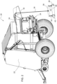
FIG. 1 is a schematic perspective view of a baler implement. -
FIG. 2 is a schematic side view of the baler implement showing a lift system raising a supply roll of a wrap material. -
FIG. 3 is a schematic side view of the supply roll. -
FIG. 4 is a schematic end view of the supply roll. -
FIG. 5 is a schematic end view showing the lift system coupled to the supply roll of the wrap material using a hanger and two lift locations. -
FIG. 6 is a schematic end view showing the lift system coupled to the supply roll of the wrap material using a single lift location. - Those having ordinary skill in the art will recognize that terms such as "above," "below," "upward," "downward," "top," "bottom," etc., are used descriptively for the figures, and do not represent limitations on the scope of the disclosure, as defined by the appended claims. Furthermore, the teachings may be described herein in terms of functional and/or logical block components and/or various processing steps. It should be realized that such block components may be comprised of any number of hardware, software, and/or firmware components configured to perform the specified functions.
- Terms of degree, such as "generally", "substantially" or "approximately" are understood by those of ordinary skill to refer to reasonable ranges outside of a given value or orientation, for example, general tolerances or positional relationships associated with manufacturing, assembly, and use of the described embodiments.
- As used herein, "e.g." is utilized to non-exhaustively list examples, and carries the same meaning as alternative illustrative phrases such as "including," "including, but not limited to," and "including without limitation." As used herein, unless otherwise limited or modified, lists with elements that are separated by conjunctive terms (e.g., "and") and that are also preceded by the phrase "one or more of," "at least one of," "at least," or a like phrase, indicate configurations or arrangements that potentially include individual elements of the list, or any combination thereof. For example, "at least one of A, B, and C" and "one or more of A, B, and C" each indicate the possibility of only A, only B, only C, or any combination of two or more of A, B, and C (A and B; A and C; B and C; or A, B, and C). As used herein, the singular forms "a", "an" and "the" are intended to include the plural forms as well, unless the context clearly indicates otherwise. Further, "comprises," "includes," and like phrases are intended to specify the presence of stated features, steps, operations, elements, and/or components, but do not preclude the presence or addition of one or more other features, steps, operations, elements, components, and/or groups thereof.
- Referring to the Figures, wherein like numerals indicate like parts throughout the several views, a baler implement is generally shown at 20. In the example implementation shown in the figures and described herein, the
baler implement 20 is configured to produce a bale having a cylindrical shape, and may be referred to as a round baler. However, it should be appreciated that the baler implement 20 may be configured differently than described herein, and that the teachings of the disclosure may apply to implements other than the round baler described herein. - The baler implement 20 accumulates cut crop material, and forms the accumulated crop material into a bale. In the example implementation described herein, the bale has a cylindrical shape, and may be referred to as a round bale. Generally, the baler implement 20 accumulates the crop material in a bale forming chamber, wherein the baler implement 20 forms the crop material into the round bale. The manner, process, and/or features used to form the crop material into the round bale in the bale forming chamber are known to those skilled in the art, are not pertinent to the teachings of this disclosure, and are therefore not described in detail herein.
- Referring to
FIGS. 1 and2 , the baler implement 20 includes an implementbody 22. The implementbody 22 may include one or more panels that form an exterior surface of the baler implement 20, as well as the frame and other support members that support the panels and other components of the baler implement 20. The baler implement 20 includes awrap system 24 that is attached to the implementbody 22. Thewrap system 24 includes asupply roll 26 of awrap material 28 that is supported relative to the implementbody 22 in an installedposition 30. - The
supply roll 26 of thewrap material 28 includes a width that is substantially equal to, or perhaps slightly larger than, a height (or length) of the round bale. Thewrap material 28 may include a film, mesh, net, or other material suitable for wrapping around a circumference of the round bale to secure the shape and/or form of the round bale, and/or to protect the round bale from moisture intrusion. For example, thewrap material 28 may include, but is not limited to, a net or a plastic film that is wound around the circumference of the round bale. - The
wrap system 24 is configured for wrapping thewrap material 28 around the formed round bale in the bale forming chamber of the baler implement 20. As such, thewrap system 24 un-winds thewrap material 28 from thesupply roll 26 of thewrap material 28 and feeds thewrap material 28 into the bale forming chamber, where thewrap material 28 is wound around the circumference of the round bale. The specific manner in which thewrap system 24 un-winds thewrap material 28, feeds thewrap material 28 into the bale forming chamber, and wraps thewrap material 28 around the round bale within the bale forming chamber is not pertinent to the teachings of this disclosure, are known to those skilled in the art, and are therefore not described in detail herein. - Referring to
FIGS. 1 and2 , the baler implement 20 further includes alift system 32. Thelift system 32 is operable to raise thesupply roll 26 of thewrap material 28, relative to the implementbody 22, into the installedposition 30. As shown inFIG. 2 , thelift system 32 may include aline actuator 34 having alift line 36. Thelift line 36 extends from the lift location downward for engagement with thesupply roll 26 of thewrap material 28. Thelift line 36 may include, but is not limited to, a cable, a rope, a chain, a strap, etc. Thelift line 36 may include or may be attached to ahanger 38 for engaging liftingbands 40 associated with thesupply roll 26 of thewrap material 28. - The line actuator 34 may include a mechanism capable of retracting and extending the
lift line 36 in order to raise and lower thesupply roll 26 of thewrap material 28. For example, theline actuator 34 may include a winding device having a rotatable member that is rotatable about an axis, and that is capable of winding and un-winding thelift line 36 in order to raise and lower thesupply roll 26 of thewrap material 28. For example, theline actuator 34 may include, but is not limited to, an electrically driven winch or a manually operated winch that winds and unwinds thelift line 36 to raise and lower the roll. It should be appreciated that thelift system 32 may include a device other than the exemplary embodiments of theline actuator 34 described herein for raising thesupply roll 26 of thewrap material 28. - Referring to
FIGS. 3 and 4 , thesupply roll 26 of thewrap material 28 includes acore 42. Thecore 42 extends along a centrallongitudinal axis 44, between a firstaxial end 46 and a secondaxial end 48. Thecore 42 includes acircumferential wall surface 50 forming a cylindrical shape that is concentric with the centrallongitudinal axis 44. The core 42 may include a hollow tubular structure, or a solid structure. The core 42 may be manufactured from, but is not limited to, a cardboard material, a plastic material, or a metal material. Thecore 42 provides a rigid structure against which thewrap material 28 may be wound or wrapped, and supports thewrap material 28 while in thewrap system 24 of the baler implement 20. - The
wrap material 28 includes a width spanning along the centrallongitudinal axis 44 of the core 42, between the firstaxial end 46 and the secondaxial end 48 of thecore 42. Thewrap material 28 further includes a length that is wound about thecircumferential wall surface 50 of thecore 42. Thewrap material 28 is wound about the core 42 to form several layers of thewrap material 28 as is understood in the art. Thewrap material 28 wound around thecore 42 defines anexterior circumference 52. Theexterior circumference 52 of thewrap material 28 is substantially perpendicular to the centrallongitudinal axis 44 of the core 42, and is defined by the outer most layer of thewrap material 28. - A
roll cover 54 may be wrapped around theexterior circumference 52 of thewrap material 28 for protection. Theroll cover 54 may include, but is not limited to, a solid plastic sheet that is wrapped around theexterior circumference 52 of thewrap material 28 and fully covers the length of thewrap material 28. - The
core 42 and thewrap material 28 cooperate to define a combined center ofgravity 56 of thesupply roll 26. If equipped with theroll cover 54, theroll cover 54 may further contribute to define the combined center ofgravity 56 of thesupply roll 26. As is understood by those in the art, the combined center ofgravity 56 of thesupply roll 26 is a point from which the weight of thesupply roll 26 may be considered to act. - The
supply roll 26 further includes anaxial position identifier exterior circumference 52 of thewrap material 28. Theaxial position identifier gravity 56 to define a desiredlift location lift location supply roll 26 from when raising thesupply roll 26 via thelift system 32 into thewrap system 24 of the baler implement 20. - Referring to
FIG. 5 , as described above, thelift system 32 may utilize thehanger 38 attached to thelift line 36. Thehanger 38 has a single attachment location to thelift line 36, but includes two attachment locations for supporting thesupply roll 26, i.e., afirst pocket 62 and asecond pocket 64. Thefirst pocket 62 and thesecond pocket 64 are spaced equidistance from thelift line 36. Accordingly, in order to secure thesupply roll 26 to thehanger 38 of thelift system 32, the axial position identifier may include a firstaxial position identifier 58A and a secondaxial position identifier 58B spaced apart from each other along the centrallongitudinal axis 44 of thecore 42 and across the combined center ofgravity 56 of thesupply roll 26. As such, the firstaxial position identifier 58A and the secondaxial position identifier 58B are spaced equidistantly from the combined center ofgravity 56 of thesupply roll 26 on opposing axial sides of the combined center ofgravity 56 along the centrallongitudinal axis 44 of thecore 42. - As noted above, the combined center of
gravity 56 of thesupply roll 26 is the point at which gravitational forces may be considered to act on thesupply roll 26. By lifting thesupply roll 26 at two locations that are spaced equidistant from and on opposing sides of the combined center ofgravity 56, thesupply roll 26 is balanced while raised, and will not significantly shift, tilt or lean. The firstaxial position identifier 58A may be positioned relative to the combined center ofgravity 56 to define a desiredfirst lift location 60A. Similarly, the secondaxial position identifier 58B may be positioned relative to the combined center ofgravity 56 to define a desiredsecond lift location 60B. The firstaxial position identifier 58A and the secondaxial position identifier 58B identify the two desiredlifting locations first pocket 62 and thesecond pocket 64 of thehanger 38 from which to lift thesupply roll 26 from. Accordingly, a user may easily identify the desiredlift locations supply roll 26 to thehanger 38 via the firstaxial position identifier 58A and the secondaxial position identifier 58B. - If the
hanger 38 is not used to raise thesupply roll 26, thesupply roll 26 may be directly attached to thelift line 36, whereby thesupply roll 26 is engaged at only a single desiredlift location 60. Referring toFIG. 6 , when lifting from the single desiredlift location 60, thelift line 36 may be secured to thesupply roll 26 along the centrallongitudinal axis 44 at the combined center ofgravity 56. As such, theaxial position identifier 58 may be positioned along the centrallongitudinal axis 44 at the combined center ofgravity 56 to identify the desiredlift location 60 for a single location lift. - The
axial position identifier exterior circumference 52 of thewrap material 28. For example, theaxial position identifier exterior circumference 52 of thewrap material 28. Theaxial position identifier exterior circumference 52 of thewrap material 28, e.g., a dot, dash, star, etc. In other implementations, theaxial position identifier exterior circumference 52 of thewrap material 28. - As noted above, the
axial position identifier exterior circumference 52 of thewrap material 28. In other implementations, theaxial position identifier band 40 wrapped around theexterior circumference 52 of thewrap material 28 in a manner that prevents relative movement between the liftingband 40 and thesupply roll 26, e.g., a tight frictional engagement. It is contemplated that the liftingband 40 utilized for theaxial position identifier loop 66, hook, or other feature configured for engaging thehanger 38 and/or thelift line 36 to attach thesupply roll 26 thereto. - In other implementations, if the
supply roll 26 is equipped with theroll cover 54, theaxial position identifier roll cover 54, such that theroll cover 54 is disposed between theaxial position identifier wrap material 28. For example, theaxial position identifier roll cover 54. In other implementations, if theroll cover 54 is clear and/or generally translucent, theaxial position identifier exterior circumference 52 of thewrap material 28 underneath theroll cover 54, such that theaxial position identifier roll cover 54. - A method of manufacturing the
supply roll 26 is also provided. The method includes winding thewrap material 28 around thecircumferential wall surface 50 of thecore 42. Thewrap material 28 may then be covered with theroll cover 54 if desired. - A combined center of
gravity 56 of thecore 42 and thewrap material 28 is then determined. If thesupply roll 26 includes theroll cover 54, it should be appreciated that the combined center ofgravity 56 includes theroll cover 54 in combination with thecore 42 and thewrap material 28. The combined center ofgravity 56 may be determined by, for example, balancing thesupply roll 26 to identify the combined center ofgravity 56. In other implementations, the combined center ofgravity 56 may be determined for a specifictest supply roll 26, whereby the combined center ofgravity 56 for the specifictest supply roll 26 may be presumed to approximate the combined center ofgravity 56 of all future supply rolls 26 of the same size, material, and construction. - Once the combined center of
gravity 56 is determined, theaxial position identifier exterior circumference 52 of thewrap material 28 or theroll cover 54. The position of theaxial position identifier gravity 56 at the defined lift location. Affixing theaxial position identifier exterior circumference 52 of thewrap material 28 may include, but is not limited to, painting or marking theaxial position identifier exterior circumference 52 of thewrap material 28 or theroll cover 54. In other implementations, affixing theaxial position identifier exterior circumference 52 of thewrap material 28 may include, but is not limited to, securing the liftingband 40 or strap around thesupply roll 26. - If the
supply roll 26 is to be raised with a single lift location, then affixing theaxial position identifier 58 on theexterior circumference 52 of thewrap material 28 includes affixing theaxial position identifier 58 at the location along the centrallongitudinal axis 44 corresponding to the location of the combined center ofgravity 56 along the centrallongitudinal axis 44. - If the
supply roll 26 is to be raised with two lift locations, i.e., the first and second desired liftinglocations axial position identifier exterior circumference 52 of thewrap material 28 includes affixing the firstaxial position identifier 58A at the first desiredlift location 60A relative to the combined center ofgravity 56, and affixing the secondaxial position identifier 58B at the second desiredlift location 60B relative to the combined center ofgravity 56. The firstaxial position identifier 58A and the secondaxial position identifier 58B are affixed equidistantly from the combined center ofgravity 56 on opposing axial sides of the combined center ofgravity 56 along the centrallongitudinal axis 44 of thecore 42. - The detailed description and the drawings or figures are supportive and descriptive of the disclosure, but the scope of the disclosure is defined solely by the claims. While some of the best modes and other embodiments for carrying out the claimed teachings have been described in detail, various alternative designs and embodiments exist for practicing the disclosure defined in the appended claims.
Claims (12)
- A supply roll (26) for a wrap system (24) of a baler implement (20), the supply roll (26) comprising:a core (42) extending along a central longitudinal axis (44) between a first axial end (46) and a second axial end (48), wherein the core (42) includes a circumferential wall surface (50) forming a cylindrical shape concentric with the central longitudinal axis (44);a wrap material (28) having a width spanning along the central longitudinal axis (44) between the first axial end (46) and the second axial end (48) of the core (42), and a length wound about the circumferential wall surface (50) of the core (42), wherein the wrap material (28) defines an exterior circumference (52) substantially perpendicular to the central longitudinal axis (44);wherein the core (42) and the wrap material (28) cooperate to define a combined center of gravity (56); andan axial position identifier (58, 58A, 58B) on the exterior circumference (52) of the wrap material (28) and positioned relative to the combined center of gravity (56) to define a desired lift location.
- The supply roll (26) set forth in claim 1, wherein the axial position identifier (58, 58A, 58B) includes a first axial position identifier (58A) and a second axial position identifier (58B) spaced apart from each other along the central longitudinal axis (44) and across the combined center of gravity (56).
- The supply roll (26) set forth in claim 1 or 2, wherein the first axial position identifier (58A) and the second axial position identifier (58B) are spaced equidistantly from the combined center of gravity (56) on opposing axial sides of the combined center of gravity (56) along the central longitudinal axis (44).
- The supply roll (26) according to at least one of the preceding claims, wherein the axial position identifier (58, 58A, 58B) is positioned along the central longitudinal axis (44) at the combined center of gravity (56).
- The supply roll (26) according to at least one of the preceding claims, wherein the axial position identifier (58, 58A, 58B) includes a marking printed on the exterior circumference (52) of the wrap material (28).
- The supply roll (26) according to at least one of the preceding claims, wherein the axial position identifier (58, 58A, 58B) includes a band (40) wrapped around the exterior circumference (52) of the wrap material (28).
- The supply roll (26) according to at least one of the preceding claims, further comprising a roll cover (54) disposed between the axial position identifier (58, 58A, 58B) and the wrap material (28).
- The supply roll (26) according to at least one of the preceding claims, wherein the axial position identifier (58, 58A, 58B) includes a marking printed on the roll cover (54).
- The supply roll (26) according to at least one of the preceding claims, wherein the axial position identifier (58, 58A, 58B) encircles the exterior circumference (52) of the wrap material (28).
- A method of manufacturing a supply roll (26) of a wrap material (28) for a wrap system (24) of a baler implement (20), the method comprising:winding the wrap material (28) around a circumferential wall surface (50) of a core (42);determining a combined center of gravity (56) of the core (42) and the wrap material (28); andaffixing an axial position identifier (58, 58A, 58B) on an exterior circumference (52) of the wrap material (28) relative to the combined center of gravity (56) at a defined lift location.
- The method set forth in claim 10, further comprising covering the wrap material (28) with a roll cover (54) prior to affixing the axial position identifier (58, 58A, 58B) on the exterior circumference (52) of the wrap material (28).
- The method set forth in claim 10 or 11, wherein affixing the axial position identifier (58, 58A, 58B) on the exterior circumference (52) of the wrap material (28) includes affixing a first axial position identifier (58A) and affixing a second axial position identifier (58B) equidistantly from the combined center of gravity (56) on opposing axial sides of the combined center of gravity (56) along a central longitudinal axis (44) of the core (42).
Applications Claiming Priority (2)
| Application Number | Priority Date | Filing Date | Title |
|---|---|---|---|
| US202263267197P | 2022-01-27 | 2022-01-27 | |
| US17/933,522 US12382872B2 (en) | 2022-01-27 | 2022-09-20 | Net wrap roll with lift hook location markings |
Publications (2)
| Publication Number | Publication Date |
|---|---|
| EP4218398A1 true EP4218398A1 (en) | 2023-08-02 |
| EP4218398B1 EP4218398B1 (en) | 2026-04-08 |
Family
ID=83690486
Family Applications (1)
| Application Number | Title | Priority Date | Filing Date |
|---|---|---|---|
| EP22200693.4A Active EP4218398B1 (en) | 2022-01-27 | 2022-10-11 | Net wrap roll with lift hook location markings |
Country Status (2)
| Country | Link |
|---|---|
| US (1) | US12382872B2 (en) |
| EP (1) | EP4218398B1 (en) |
Citations (4)
| Publication number | Priority date | Publication date | Assignee | Title |
|---|---|---|---|---|
| US20050211817A1 (en) * | 2004-03-16 | 2005-09-29 | Rudolf Muench | Apparatus and method for marking a J-line |
| US20060005512A1 (en) * | 2003-05-08 | 2006-01-12 | Anstey Henry D | Large round bale wrapped in protective wrapping and method for producing such a wrapped bale |
| EP3593625A1 (en) * | 2018-07-13 | 2020-01-15 | Deere & Company | Net wrap lifting device |
| US20220015300A1 (en) * | 2020-07-20 | 2022-01-20 | Deere & Company | Round baler with bale holder in gate |
Family Cites Families (1)
| Publication number | Priority date | Publication date | Assignee | Title |
|---|---|---|---|---|
| EP4037467B1 (en) * | 2019-10-02 | 2025-08-06 | McHale Engineering | Axially protruding continuous round baler |
-
2022
- 2022-09-20 US US17/933,522 patent/US12382872B2/en active Active
- 2022-10-11 EP EP22200693.4A patent/EP4218398B1/en active Active
Patent Citations (4)
| Publication number | Priority date | Publication date | Assignee | Title |
|---|---|---|---|---|
| US20060005512A1 (en) * | 2003-05-08 | 2006-01-12 | Anstey Henry D | Large round bale wrapped in protective wrapping and method for producing such a wrapped bale |
| US20050211817A1 (en) * | 2004-03-16 | 2005-09-29 | Rudolf Muench | Apparatus and method for marking a J-line |
| EP3593625A1 (en) * | 2018-07-13 | 2020-01-15 | Deere & Company | Net wrap lifting device |
| US20220015300A1 (en) * | 2020-07-20 | 2022-01-20 | Deere & Company | Round baler with bale holder in gate |
Also Published As
| Publication number | Publication date |
|---|---|
| US20230240192A1 (en) | 2023-08-03 |
| US12382872B2 (en) | 2025-08-12 |
| EP4218398B1 (en) | 2026-04-08 |
Similar Documents
| Publication | Publication Date | Title |
|---|---|---|
| EP4218398B1 (en) | Net wrap roll with lift hook location markings | |
| GB2238333A (en) | Telescopic mast | |
| US20130200202A1 (en) | Rope coiler | |
| US5174073A (en) | Shielding system and method | |
| US20190017318A1 (en) | System and Method for Transport and Installation of a Screen Assembly | |
| EP1805089B1 (en) | Netting material with breathable material panels and method of wrapping with netting material | |
| CA2463216A1 (en) | Unwind spool assembly | |
| US5735230A (en) | Apparatus for supporting flags on automobile antennas | |
| ES2818525T3 (en) | A protective foil placement system | |
| US20050155284A1 (en) | Plant and flower wind screen including attached stakes | |
| US5722613A (en) | Easy reel device | |
| US7306100B1 (en) | Protective cover for fiber cable reels and method for protecting same | |
| US20240327166A1 (en) | Handheld coiled material dispenser | |
| US6035968A (en) | Collapsible hunting stand | |
| EP2591926B1 (en) | Connecting apparatus for towing vehicles | |
| EP4218399A2 (en) | Net loading hanger with functional hooks | |
| US20140034771A1 (en) | Tarp depolying apparatus and method for uneven loads on flat bed | |
| US8297228B2 (en) | Feed support and bale ring mover for use inside a bale ring | |
| CN211002690U (en) | Steel wire disc long-distance transportation protective sleeve | |
| US20080105332A1 (en) | Aerial Saw with Landing Legs | |
| US11700799B2 (en) | Polytunnel structure with stepped support members for holding rotatable beam | |
| EP1954587B1 (en) | A wrapping material with fastener | |
| CN210259359U (en) | Strip steel coil binding device | |
| US6234420B1 (en) | String feeding device for supporting plants | |
| JP3215451U (en) | Sheet winding balloon |
Legal Events
| Date | Code | Title | Description |
|---|---|---|---|
| PUAI | Public reference made under article 153(3) epc to a published international application that has entered the european phase |
Free format text: ORIGINAL CODE: 0009012 |
|
| STAA | Information on the status of an ep patent application or granted ep patent |
Free format text: STATUS: THE APPLICATION HAS BEEN PUBLISHED |
|
| AK | Designated contracting states |
Kind code of ref document: A1 Designated state(s): AL AT BE BG CH CY CZ DE DK EE ES FI FR GB GR HR HU IE IS IT LI LT LU LV MC ME MK MT NL NO PL PT RO RS SE SI SK SM TR |
|
| STAA | Information on the status of an ep patent application or granted ep patent |
Free format text: STATUS: REQUEST FOR EXAMINATION WAS MADE |
|
| 17P | Request for examination filed |
Effective date: 20240202 |
|
| RBV | Designated contracting states (corrected) |
Designated state(s): AL AT BE BG CH CY CZ DE DK EE ES FI FR GB GR HR HU IE IS IT LI LT LU LV MC ME MK MT NL NO PL PT RO RS SE SI SK SM TR |
|
| GRAP | Despatch of communication of intention to grant a patent |
Free format text: ORIGINAL CODE: EPIDOSNIGR1 |
|
| STAA | Information on the status of an ep patent application or granted ep patent |
Free format text: STATUS: GRANT OF PATENT IS INTENDED |
|
| INTG | Intention to grant announced |
Effective date: 20251208 |
|
| GRAS | Grant fee paid |
Free format text: ORIGINAL CODE: EPIDOSNIGR3 |
|
| GRAA | (expected) grant |
Free format text: ORIGINAL CODE: 0009210 |
|
| STAA | Information on the status of an ep patent application or granted ep patent |
Free format text: STATUS: THE PATENT HAS BEEN GRANTED |
|
| AK | Designated contracting states |
Kind code of ref document: B1 Designated state(s): AL AT BE BG CH CY CZ DE DK EE ES FI FR GB GR HR HU IE IS IT LI LT LU LV MC ME MK MT NL NO PL PT RO RS SE SI SK SM TR |
|
| REG | Reference to a national code |
Ref country code: CH Ref legal event code: F10 Free format text: ST27 STATUS EVENT CODE: U-0-0-F10-F00 (AS PROVIDED BY THE NATIONAL OFFICE) Effective date: 20260408 Ref country code: GB Ref legal event code: FG4D |
|
| REG | Reference to a national code |
Ref country code: DE Ref legal event code: R096 Ref document number: 602022033923 Country of ref document: DE |