EP4218205B1 - Automated setup of multi-level, multi-domain network automation functions - Google Patents
Automated setup of multi-level, multi-domain network automation functions Download PDFInfo
- Publication number
- EP4218205B1 EP4218205B1 EP20780668.8A EP20780668A EP4218205B1 EP 4218205 B1 EP4218205 B1 EP 4218205B1 EP 20780668 A EP20780668 A EP 20780668A EP 4218205 B1 EP4218205 B1 EP 4218205B1
- Authority
- EP
- European Patent Office
- Prior art keywords
- network
- management
- function
- network automation
- level
- Prior art date
- Legal status (The legal status is an assumption and is not a legal conclusion. Google has not performed a legal analysis and makes no representation as to the accuracy of the status listed.)
- Active
Links
Images


Classifications
-
- H—ELECTRICITY
- H04—ELECTRIC COMMUNICATION TECHNIQUE
- H04L—TRANSMISSION OF DIGITAL INFORMATION, e.g. TELEGRAPHIC COMMUNICATION
- H04L41/00—Arrangements for maintenance, administration or management of data switching networks, e.g. of packet switching networks
- H04L41/04—Network management architectures or arrangements
- H04L41/044—Network management architectures or arrangements comprising hierarchical management structures
-
- H—ELECTRICITY
- H04—ELECTRIC COMMUNICATION TECHNIQUE
- H04L—TRANSMISSION OF DIGITAL INFORMATION, e.g. TELEGRAPHIC COMMUNICATION
- H04L41/00—Arrangements for maintenance, administration or management of data switching networks, e.g. of packet switching networks
- H04L41/08—Configuration management of networks or network elements
- H04L41/0803—Configuration setting
- H04L41/0806—Configuration setting for initial configuration or provisioning, e.g. plug-and-play
-
- H—ELECTRICITY
- H04—ELECTRIC COMMUNICATION TECHNIQUE
- H04L—TRANSMISSION OF DIGITAL INFORMATION, e.g. TELEGRAPHIC COMMUNICATION
- H04L41/00—Arrangements for maintenance, administration or management of data switching networks, e.g. of packet switching networks
- H04L41/08—Configuration management of networks or network elements
- H04L41/0876—Aspects of the degree of configuration automation
- H04L41/0886—Fully automatic configuration
-
- H—ELECTRICITY
- H04—ELECTRIC COMMUNICATION TECHNIQUE
- H04L—TRANSMISSION OF DIGITAL INFORMATION, e.g. TELEGRAPHIC COMMUNICATION
- H04L41/00—Arrangements for maintenance, administration or management of data switching networks, e.g. of packet switching networks
- H04L41/08—Configuration management of networks or network elements
- H04L41/0895—Configuration of virtualised networks or elements, e.g. virtualised network function or OpenFlow elements
-
- H—ELECTRICITY
- H04—ELECTRIC COMMUNICATION TECHNIQUE
- H04L—TRANSMISSION OF DIGITAL INFORMATION, e.g. TELEGRAPHIC COMMUNICATION
- H04L41/00—Arrangements for maintenance, administration or management of data switching networks, e.g. of packet switching networks
- H04L41/40—Arrangements for maintenance, administration or management of data switching networks, e.g. of packet switching networks using virtualisation of network functions or resources, e.g. SDN or NFV entities
Definitions
- At least some example embodiments relate to a cognitive autonomous network (CAN), and in particular to an automated setup of multi-level, multi-domain network automation functions (NAFs) in a network management system of a mobile communications network, such as a 5G network and other (future) generations of wireless/mobile networks.
- CAN cognitive autonomous network
- NAFs multi-level, multi-domain network automation functions
- NAFs Network Automation Functions
- This learning shall be based on all kinds of data available in the network (including, for example, performance information, failures, configuration data, network planning data, or user and service-related data) as well as from the actions and the corresponding impact of the OAM function itself.
- the learning and the knowledge built from the learned information shall thereby increase the autonomy of the OAM functions.
- FRENZEL CHRISTOPH ET AL "Dynamic, context-specific SON management driven by operator objectives", 2014 IEEE NETWORK OPERATIONS AND MANAGEMENT SYMPOSIUM (NOMS), IEEE, 5 May 2014 (2014-05-05), pages 1-8 ) discloses techniques for the management and operation of a self-organizing network-enabled mobile network.
- a series of high-level models are provided which at design time provide a SON Function Configuration Parameter value (SCV) policy which defines for each SON Function an SVC set which steers the SON Function to fulfil the technical objectives under a specific context.
- SCV SON Function Configuration Parameter value
- US 9 461 886 B2 discloses a set of reporting features for implementation by lower level SON Functions to support the observation of network SON algorithms by high level SON Functions.
- problems detected by lower level SON Function are reported to a higher level SON Function to resolve conflicts between those lower level SON Functions.
- the higher level SON Functions may be centralized and occur in the core network.
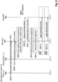
- Fig. 1 shows a schematic diagram illustrating Network Automation Function (NAF) interfaces across Management Domains (MDs).
- NAF Network Automation Function
- NAF 1 and NAF 2 are shown on the same management domain of a network management system (network management system architecture) of a cognitive autonomous network in a mobile communications network, such as a 5G network and other (future) generations of wireless/mobile networks.
- network management system network management system architecture
- Fig. 1 shows internals of NAF 1 with NAF "stages”: Data collection, Analytics, Decision, Actuation and a Knowledge Repository; note that not all of the building blocks have to be present for every NAF.
- Fig. 1 external interfaces of NAF 1 and NAF 2 are shown in Fig. 1 , which comprise external interfaces for (closed-loop) runtime operations:
- external interfaces of NAF 1 and NAF 2 comprise external interfaces for management (at both design- and run-time):
- Each NAF is associated with a "management domain" containing one or multiple NAF functions.
- management domains have:
- a "hierarchical" setup of multiple management domains contains two or more "levels" in the management domain hierarchy. This is shown in Fig. 2 , introducing level 1 as the lowest level where NAFs appear and level 0 being the level of actual physical or virtual network resources.
- a NAF at any level has the introduced interfaces IN and/or OUT, NAF control, and NAF exposure.
- Level 1 NAFs directly manipulate network configuration parameters of the (level 0) physical and virtual NFs, i.e., Level 1 NAFs do not manage other lower level NAFs via the "NAF control" interface, as shown in Fig. 2 .
- a critical task of NAFs at level L is to manage NAFs in other management domains on level L-1.
- an NAF at level 2 (also referred to as L2 NAF) provides, via a control interface of an NAF at level 1 (also referred to as L1 NAF), specific KPI target values to be achieved by the L1 NAF, and the L2 NAF provides, via its OUT interface, e.g., configuration management and aggregated KPI information which assist the L1 NAF on how to achieve the given target.
- Managing the NAF implies setting inputs, controls and outputs of the NAF that need to be specified for the NAF to operate as desired. For instance, taking the SON policy NRM [3GPP-TS 28.628] as an example, managing the NAF refers to setting, e.g.,
- MARO Multi-Aspect Resource Optimization
- domains here are typically RAN, edge cloud, core and transport management at level 2, and "end-to-end (e2e)" slicing management at level 3.
- a target setting on an NAF control interface is done as follows:
- MARO [MARO] is concerned with the operational phase.
- MARO is concerned with the operational phase.
- bootsstrapping applicable, e.g., to MARO, is explicitly addressed with a new automated method.
- Fig. 5 illustrates hierarchical relationships of loops in ETSI ZSM.
- Cases 1a, 1b and 1c are shown, in which in Case 1a loops 1 and 2 both are included in an e2e management domain.
- Case 1b loop 1 is included in the e2e management domain
- loop 2 is included in a management domain e.g. of the same operator.
- Case 1c loop 1 is included in a management domain of operator A
- loop 2 is included in a management domain of operator B.
- An interface between loop 1 and loop 2 is indicated by an arrow between the loops.
- NAF-SeF NAF Setup Function
- the NAF-SeF has the configuration of NAF 1 shown in Fig. 1
- its Knowledge part on level L is a knowledge repository that stores descriptions and operational profiles of existing NAFs as well as Management Domain (MD) knowledge for levels L and L-1.
- MD Management Domain
- the evaluation is based on the following inputs (1) to (3) to the NAF-SeF:
- the output of the NAF-SeF is an operational profile of the new NAF.
- NAF-SeF 61 is associated with management domain 62a.
- management domain 62a comprises NAF-SeF 61 and an (existing) NAF 63a.
- the management domain 62a is not limited to comprising only one NAF 63a and may comprise two or more NAFs.
- the management domain 62b comprises an NAF-SeF and an (existing) NAF 63b.
- the management domain 62b is not limited to comprising only one NAF 63b and may comprise two or more NAFs.
- a new NAF 64 is to be set up in a management domain 65a associated with level L-1 of the management domain hierarchy. Also management domain 65b and management domain 65c are associated with level L-1. In the example of Fig. 6 , management domain 65a comprises the new NAF 64 to be set up. However, the management domain 65a is not limited to comprising only the new NAF 64, and may further comprise one or more (existing) NAFs.
- Management domain 65b comprises an (existing) NAF 66b
- management domain 65c comprises an (existing) NAF 66c.
- management domains 65b and 65c are not limited thereto and may comprise two or more NAFs.
- a control and exposure interface 67 is used to acquire the self-description from the new NAF 64 (i.e. input (1)) and to apply the output operational profile to the new NAF 64.
- the NAF-SeF 61 uses any available interface to access operational knowledge, e.g., control and exposure interfaces (not shown in Fig. 6 ) of the NAF-SeF 61 to one or more level L NAFs 63a, 63b, including a level L NAF responsible for the operational configuration of the L-1 NAF.
- operational knowledge e.g., control and exposure interfaces (not shown in Fig. 6 ) of the NAF-SeF 61 to one or more level L NAFs 63a, 63b, including a level L NAF responsible for the operational configuration of the L-1 NAF.
- NAF 63a is responsible for the operational configuration of NAF 66b
- NAF 63b is responsible for the operational configuration of NAFs 66b and 66c.
- control and exposure interfaces (not shown in Fig. 6 ) of the NAF-SeF 61 to other L-1 NAFs (NAFs 66b, 66c in Fig. 6 ) are used.
- operator policies governing the behavior of NAF-SeF 61, are configured through a control and exposure interface 68 of the NAF-SeF 61.
- FIG. 7 shows a flowchart illustrating a method of implementing a setup function according to at least some example embodiments.
- the setup function is associated with a management domain of a network management system (network management system architecture) of a mobile communications network.
- the management domain comprises one or more network automation functions (NAFs), and the management domain is associated with a specific level of a management domain hierarchy of the network management system architecture.
- the setup function is NAF-SeF 61, and its management domain is management domain 62a of the second management domains 62a, 62b.
- the setup function stores first information indicating descriptions and operational profiles of one or more first network automation functions of one or more first management domains of the network management system.
- the first management domains are associated with a level L-1 of the management domain hierarchy.
- the one or more first network automation functions are NAFs 66b and 66c
- the one or more first management domains are MDs 65a, 65b and 65c
- level L-1 is Level 1.
- the setup function further stores second information indicating management domain knowledge about one or more second management domains of the network management system architecture and about the one or more first management domains.
- the second management domains are associated with a level L of the management domain hierarchy.
- the one or more second management domains are MDs 62a and 62b, and level L is Level 2.
- step S701 information (third information) is acquired, which indicates a description of an NAF (third network automation function) which is to be set up in a management domain of the first management domains associated with the level L-1.
- NAF third network automation function
- the third NAF is NAF 64
- the management domain is management domain 65a.
- step S703 an evaluation of the third information against at least one of the first information and the second information is performed. Then the process proceeds to step S705.
- step S705 an operational profile of the third network automation function is determined based on the evaluation. Then the process proceeds to step S707.
- step S707 the third network automation function is set up in the management domain associated with the level L-1 by applying the operational profile to the third network automation function. Then the process of Fig. 7 ends.
- L is a positive integer equal to or greater than 2.
- the process shown in Fig. 7 is executed each time a new NAF is to be set up.
- the management domain which the setup function is associated with is one of the second management domains associated with the level L.
- NAF-SeF 61 is associated with MD 62a of Level 2.
- the management domain which the setup function is associated with and the management domain which the third network automation function is associated with are similar management domains.
- similar means that e.g. MD 62a and MD 65a are associated with the same or similar part of the mobile communications network, e.g. radio access network or core network, which will be described in application examples later on.
- At least some example embodiments are applicable to multi-domain scenarios which e.g. comply with Service-Based Management Architecture (SBMA) principles, i.e. without hierarchy, where only service providers and consumers exists.
- SBMA Service-Based Management Architecture
- the at least some example embodiments allow to take advantage of the accumulated knowledge at the NAF (master).
- Fig. 8 shows a signaling diagram illustrating interaction between different components of a network management system of a mobile communications network.
- Fig. 8 illustrates interaction, e.g. via interface 67 shown in Fig. 6 , between NAF-SeF 810 on level L (e.g. NAF-SeF 61 in the example of Fig. 6 ) and a new NAF 820 on level L-1 (e.g. NAF 64 in the example of Fig. 6 ), existing NAFs 830 on level L-1 (e.g. NAFs 66b, 66c in the example of Fig. 6 ), and network management system of MDs L-1, L 840 (e.g. MDs 62a, 62b, 65a, 65b, 65c in the example of Fig. 6 ).
- L e.g. NAF-SeF 61 in the example of Fig. 6
- a new NAF 820 on level L-1 e.g. NAF 64 in the example of Fig.
- Step S8001 illustrates continuous acquisition of operational knowledge on MDs 840 by NAF-SeF 810.
- Step S8003 illustrates the existing NAFs 830 sending their self-description and operational profiles to NAF-SeF 810.
- Step S8005 illustrates that NAF-SeF 810 stores the information sent from MDs 840 and existing NAFs 830 as record to its knowledge repository. For example, the NAF-SeF 810 identifies NAF type, context, etc. from this information.
- NAF-SeF 810 at level L requests (S8009) and the new NAF 820 provides (S8011) its self-description.
- the NAF-SeF 810 for level L checks the self-description of the new NAF 820 versus entries in the knowledge repository for level L-1 NAFs 830 considering knowledge about the MDs 840 (S8013).
- a specific algorithm determines "similarity" of the new NAF 820 with existing NAFs 830, e.g., in a statistical sense or using transfer learning, and returns an operational profile or an indication that no such profile could be found.
- the returned profile is a "best matching" existing profile, a specifically computed new profile or a combination of those variants.
- the identified profile is configured via the control service (e.g. interface 67 according to the example of Fig. 6 ) to the new NAF 820.
- the control service e.g. interface 67 according to the example of Fig. 6
- the applied operational profile is the operational profile of the new NAF 820 found by the "similarity algorithm”.
- step S8017b a default profile is applied to the new NAF 820.
- the “similarity algorithm” is not specifically restricted.
- the “similarity algorithm” is governed by operator policies, related to both:
- the new NAF 820 on level L-1 is configured with an operational profile based on the operational knowledge available, and thus ready to operate.
- An NAF on level L (e.g. NAF 63a in the example of Fig. 6 ) supposed to do continuous management on the new NAF 820 (NAF 64 in Fig. 6 ) on level L-1 can then directly start with actions via its control services interface to the new NAF 820 (NAF 64) on level L-1.
- the NAF 63a on level L also retrieves via its exposure services interface the initial operational profile configured by the NAF-SeF 810 (NAF-SeF 61).
- the NAF 63a on level L directly retrieves the initial operational profile via the exposure service (e.g. exposure and control interface between NAF-SeF 61 and NAF 63a, not shown in Fig. 6 ) of the NAF-SeF 810 (NAF-SeF 61).
- Application example 1 3GPP SA5 network slicing
- Fig. 9 shows the mapping of at least some example embodiments to the network slicing framework defined in 3GPP SA5 [3GPP-TS 28.533], using service-based management architecture (SBMA) principles.
- SBMA service-based management architecture
- NFMFs are Level 1 NAFs
- NSSMFs are Level 2 NAFs
- NSMF is Level 3 NAF
- PNFs and VNFs are network function on Level 0.
- On Level 3 there is one management domain
- On Level 2 there are two management domains for RAN and Core, respectively
- on Level 1 there are three management domains for RAN, Edge and Core, respectively.
- the NFMFs are managed, via control and exposure services (also referred to as control and exposure interfaces) as illustrated e.g. in Fig. 6 , by NAF-SeFs on Level 2 per the respective MD like RAN, Edge, Core.
- control and exposure services also referred to as control and exposure interfaces
- NAF-SeFs on Level 2 per the respective MD like RAN, Edge, Core.
- the NSSMFs are managed by NAF-SeF on Level 3.
- the NAF-SeFs consume the exposure services to learn operational profiles of existing NAFs, (ii) obtain the self-description of a new NAF, and (iii) consume the control services to apply the determined profile for a new NAF.
- NAF-SeFs on Level 2 perform operations (i)-(iii) for Level 1 NFMFs, e.g., SON functions, and the NAF-SeF on Level 3 perform operations (i)-(iii) for Level 2 NSSMFs.
- MARO [MARO] is a specific NAF combining the described Level 2 / Level 3 functionality for a joint optimization across multiple MDs and across multiple levels.
- NAF-SeF of Level 2 MD RAN corresponds to NAF-SeF 61
- Level 2 MD RAN corresponds to MD 62a
- NSSMF of MD RAN corresponds to NAF 63a
- NFMF to be set up in Level 1 MD RAN corresponds to NAF 64
- Level 1 MD RAN corresponds to MD 65a
- the control and exposure interface between Level 2 MD RAN NAF-SeF and Level 1 MD RAN NFMF corresponds to interface 67.
- Fig. 10 shows the mapping of at least some example embodiments to ETSI ZSM Closed Loop Automation (CLA).
- CLA Closed Loop Automation
- NAFs are closed loops (CLs) in any of the management domains. It is noted that at least some example embodiments are independent from which internal parts (called “stages” in ZSM terminology) are present in the NAF (i.e. CL).
- Level 0 network functions associated with RAN, Edge Cloud and Core are managed by NAFs (CLs) of Level 1 MDs "RAN”, “Edge Cloud” and “Core”.
- the Level 1 NAFs (CLs) are managed by NAFs (CLs) of Level 2 MD associated with E2E service management.
- NAF-SeF of Level 2 corresponds to NAF-SeF 61
- Level 2 MD E2E service management corresponds to MD 62a
- Level 2 NAF (CL) on the left hand side in Fig. 10 corresponds to NAF 63a
- NAF (CL) to be set up in Level 1 MD RAN corresponds to NAF 64
- Level 1 MD RAN corresponds to MD 65a
- the control and exposure interface between Level 2 NAF-SeF and Level 1 MD RAN NAF (CL) corresponds to interface 67.
- ZSM [ZSM-009-1_Cla enab] defines "commissioning" and "operation” phases within a Closed Loop lifecycle to which at least some example embodiments apply.
- the NAF-SeF of Fig. 10 uses knowledge gained from the "operation” phase from other CLs on Levels 1 and 2, and applies it to the "commissioning" phase of Level 1 MD RAN CL.
- NAFs' "self-description" is derived from data used for instantiation of the closed loop, e.g., in form of a "CL descriptor” that is compiled at design time to be used to instantiate the CL.
- FIG. 11 illustrating a simplified block diagram of a control unit 10 that is suitable for use in practicing at least some example embodiments. According to an implementation example, the method of Fig. 7 is implemented by the control unit 10.
- the control unit 10 comprises processing resources (e.g. processing circuitry) 11, memory resources (e.g. memory circuitry) 12 and interfaces (e.g. interface circuitry) 13, which are coupled via a wired or wireless connection 14.
- processing resources e.g. processing circuitry
- memory resources e.g. memory circuitry
- interfaces e.g. interface circuitry
- the memory resources 12 are of any type suitable to the local technical environment and are implemented using any suitable data storage technology, such as semiconductor based memory devices, magnetic memory devices and systems, optical memory devices and systems, fixed memory and removable memory.
- the processing resources 11 are of any type suitable to the local technical environment, and include one or more of general purpose computers, special purpose computers, microprocessors, digital signal processors (DSPs) and processors based on a multi core processor architecture, as non limiting examples.
- the memory resources 12 comprise one or more non-transitory computer-readable storage media which store one or more programs that when executed by the processing resources 11 cause the control unit 10 to function as an NAF-SeF (e.g. NAF-SeF 61, NAF-SeF 810) as described above.
- NAF-SeF e.g. NAF-SeF 61, NAF-SeF 810
- circuitry refers to one or more or all of the following:
- circuitry applies to all uses of this term in this application, including in any claims.
- circuitry would also cover an implementation of merely a processor (or multiple processors) or portion of a processor and its (or their) accompanying software and/or firmware.
- circuitry would also cover, for example and if applicable to the particular claim element, a baseband integrated circuit or applications processor integrated circuit for a mobile phone or a similar integrated circuit in server, a cellular network device, or other network device.
- the apparatus is implemented by the control unit 10 of Fig. 11 .
Landscapes
- Engineering & Computer Science (AREA)
- Computer Networks & Wireless Communication (AREA)
- Signal Processing (AREA)
- Automation & Control Theory (AREA)
- Mobile Radio Communication Systems (AREA)
Description
- At least some example embodiments relate to a cognitive autonomous network (CAN), and in particular to an automated setup of multi-level, multi-domain network automation functions (NAFs) in a network management system of a mobile communications network, such as a 5G network and other (future) generations of wireless/mobile networks.
- With the success of Self Organizing Networks (SONs), but also its shortcom ings in terms of flexibility and adaptability to changing and complex environments, there is a strong demand for more intelligence and autonomy in network Operations, Administration and Management (OAM).
- An objective of CAN is that Network Automation Functions (NAFs) should be able to: 1) take higher level goals and derive the appropriate performance targets, 2) learn from their environment and their individual or shared experiences therein, 3) learn to contextualize their operating conditions and, 4) learn their optimal behavior fitting to the specific environment and contexts. This learning shall be based on all kinds of data available in the network (including, for example, performance information, failures, configuration data, network planning data, or user and service-related data) as well as from the actions and the corresponding impact of the OAM function itself. The learning and the knowledge built from the learned information shall thereby increase the autonomy of the OAM functions.
- Current and future networks will for a long-time support both learning based Cognitive Functions (CFs) and rule-based SON Functions (SFs). Different combinations of both kinds of functions, together called generically Network Automation Functions (NAFs), may coexist in the network at the same time, with each NAF tasked to achieve its specific objective.
-
- [ZSM-009-1_Cla enab] ZSM; Closed-loop automation; Enablers, ETSI ISG ZSM
- [ZSM-009-2_Cla_sol] ZSM; Closed-loop automation; Solutions, ETSI ISG ZSM
- [MARO] SA5 Multi-Aspect / multi-domain Resource Optimization use case in 28.861 (study SON in 5G), section 5.21
- [3GPP-TS 28.628] SON Policy NRM, V15.1.0, March 2019
- [3GPP-TS 28.533] Management and orchestration; Architecture framework, V16.4.0, June 2020
- [MDAS] Management Data Analytics Service (3GPP SA5 study), TR28.809
-
- 3GPP
- Third Generation Partnership Project
- 5G
- Fifth Generation
- API
- Application Programming Interface
- CAN
- Cognitive Autonomous Network
- CF
- Cognitive Function
- CLA
- Closed Loop Automation
- ETSI
- European Telecommunications Standards Institute
- KPI
- Key Performance Indicator
- MARO
- Multi-Aspect Resource Optimization
- MD
- Management Domain
- ML
- Machine Learning
- NAF
- Network Automation Function
- NAF-SeF
- NAF-Setup Function
- NFMF
- Network Function Management Function
- NRM
- Network Resource Model
- NSSMF
- Network Slice Subnet Management Function
- NSMF
- Network Slice Management Function
- NWDAF
- NetWork Data Analytics Function
- OAM
- Operations, Administration and Management
- PNF
- Physical Network Function
- RAN
- Radio Access Network
- SA
- System Aspects
- SBMA
- Service-Based Management Architecture
- SF
- SON Function
- SON
- Self-Organizing Network
- VNF
- Virtual Network function
- ZSM
- Zero-Touch network and Service Management (ETSI)
- FRENZEL CHRISTOPH ET AL: "Dynamic, context-specific SON management driven by operator objectives", 2014 IEEE NETWORK OPERATIONS AND MANAGEMENT SYMPOSIUM (NOMS), IEEE, 5 May 2014 (2014-05-05), pages 1-8) discloses techniques for the management and operation of a self-organizing network-enabled mobile network. A series of high-level models are provided which at design time provide a SON Function Configuration Parameter value (SCV) policy which defines for each SON Function an SVC set which steers the SON Function to fulfil the technical objectives under a specific context.
US 9 461 886 B2 - According to an aspect, there is provided a method as claimed in
claim 1, a non-transitory computer-readable storage as claimed inclaim 2 and an apparatus as claimed inclaim 3. - In the following example embodiments will be described with reference to the accompanying drawings.
-
-
Fig. 1 shows a schematic diagram illustrating Network Automation Function (NAF) interfaces across Management Domains (MDs). -
Fig. 2 shows a schematic diagram illustrating NAFs in multi-level management domains. -
Fig. 3 shows a schematic diagram illustrating instantiation of a new NAF in a multi-level management system. -
Fig. 4 shows a schematic diagram illustrating MARO. -
Fig. 5 shows a schematic diagram illustrating hierarchical relationships of loops in ZSM. -
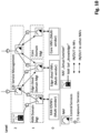
Fig. 6 shows a schematic diagram illustrating an NAF Setup Function (NAF-SeF) in a multi-level, multi-domain management architecture according to at least some example embodiments. -
Fig. 7 shows a flowchart illustrating a process of a setup function according to at least some example embodiments. -
Fig. 8 shows a signaling diagram illustrating signaling between NAFs and NAF-SeF according to at least some example embodiments. -
Fig. 9 shows a schematic diagram illustrating a first application example in which an NAF-SeF according to at least some example embodiments is applied to network slicing management in 3GPP SA5. -
Fig. 10 shows a schematic diagram illustrating a second application example in which an NAF-SeF according to at least some example embodiments is applied to network management automation in ETSI ZSM. -
Fig. 11 shows a schematic block diagram illustrating a configuration of a control unit in which example embodiments are implementable. -
Fig. 1 shows a schematic diagram illustrating Network Automation Function (NAF) interfaces across Management Domains (MDs). - In
Fig. 1 ,NAF 1 andNAF 2 are shown on the same management domain of a network management system (network management system architecture) of a cognitive autonomous network in a mobile communications network, such as a 5G network and other (future) generations of wireless/mobile networks. - As an example,
Fig. 1 shows internals ofNAF 1 with NAF "stages": Data collection, Analytics, Decision, Actuation and a Knowledge Repository; note that not all of the building blocks have to be present for every NAF. - Furthermore, external interfaces of
NAF 1 andNAF 2 are shown inFig. 1 , which comprise external interfaces for (closed-loop) runtime operations: - to receive run-time inputs (IN), e.g., performance data; and/or
- to send run-time outputs (OUT), e.g., network reconfiguration actions.
- Further, the external interfaces of
NAF 1 andNAF 2 comprise external interfaces for management (at both design- and run-time): - to receive management and control inputs via NAF-Control Services, e.g., target setting for the NAF; and
- to send management outputs via NAF-Exposure Services, e.g., performance information on if /how a set target is achieved.
- Each NAF is associated with a "management domain" containing one or multiple NAF functions. As depicted in
Fig. 1 , for example, management domains have: - i) "peer-to-peer" relationships which are "horizontal" interfaces to support multi-domain interactions, or
- ii) "hierarchical" relationships which are "vertical" interfaces to support multi-level, multi-domain interactions.
- For example, a "hierarchical" setup of multiple management domains contains two or more "levels" in the management domain hierarchy. This is shown in
Fig. 2 , introducinglevel 1 as the lowest level where NAFs appear andlevel 0 being the level of actual physical or virtual network resources. - A NAF at any level has the introduced interfaces IN and/or OUT, NAF control, and NAF exposure. As output via OUT,
Level 1 NAFs directly manipulate network configuration parameters of the (level 0) physical and virtual NFs, i.e.,Level 1 NAFs do not manage other lower level NAFs via the "NAF control" interface, as shown inFig. 2 . - On the other hand, a critical task of NAFs at level L (with L >=2) is to manage NAFs in other management domains on level L-1. Referring to
Fig. 2 , for example, such NAFs on e.g., level L=2 also provide inputs/outputs (IN/OUT) to NAFs on level L-1 AND/OR to physical /virtual network functions onlevel 0. For example, to configure network automation targets, an NAF at level 2 (also referred to as L2 NAF) provides, via a control interface of an NAF at level 1 (also referred to as L1 NAF), specific KPI target values to be achieved by the L1 NAF, and the L2 NAF provides, via its OUT interface, e.g., configuration management and aggregated KPI information which assist the L1 NAF on how to achieve the given target. - The configuration and set of these different functions at the different levels with the appropriate data required for their operation is a complex endeavor which requires to be automated in order to guarantee efficient network operations.
- When an NAF at level L-1 (L>=2) appears, e.g., when a new domain is instantiated as illustrated in
Fig. 3 , an NAF at level L does not have operational knowledge to manage the NAF on level L-1. - Managing the NAF implies setting inputs, controls and outputs of the NAF that need to be specified for the NAF to operate as desired. For instance, taking the SON policy NRM [3GPP-TS 28.628] as an example, managing the NAF refers to setting, e.g.,
- Targets (note that targets can be expressed both (concurrently or alternatingly) in a declarative (what the outcome should be) and imperative (how the outcome should be achieved) form;
- Notification conditions / thresholds;
- (Spatial and temporal) "scope" (i.e., on which resources over which time period the NAF is actually operating); and/or
- Specific subset of inputs and outputs.
- Note that the parameters above all are dependent on both the specific NAF type or purpose and the operational or deployment context.
- There is a Multi-Aspect Resource Optimization (MARO) function [MARO] as shown in
Fig. 4 , which is used (in a closed-loop way) to set and improve multi-level policies (e.g., target setting) for network slicing management, e.g. with the following mapping: - level 3: Network Slice Management Function (NSMF),
- level 2: Network Slice Subnet Management Function (NSSMF),
- level 1: Network Function Management Function (NFMF).
- The corresponding "domains" here are typically RAN, edge cloud, core and transport management at
level 2, and "end-to-end (e2e)" slicing management atlevel 3. - As an example, a target setting on an NAF control interface is done as follows:
- set a default target ("best effort") via interface (a) shown in
Fig. 3 , - collect, for a time period T, relevant information from lower levels, e.g., L-1 on NAF performance via the interface (a) and L-2 on network performance: PM, FM, CM and other data via interface (b) shown in
Fig. 3 , - only thereafter, e.g., an operational context-specific target for that NAF can be computed.
- Hence it can be summarized that MARO [MARO] is concerned with the operational phase. In contrast, according to at least some example embodiments to be described in the following a setup or "bootstrapping" applicable, e.g., to MARO, is explicitly addressed with a new automated method.
- As a further example,
Fig. 5 illustrates hierarchical relationships of loops in ETSI ZSM.Cases Case 1a loopsCase 1b,loop 1 is included in the e2e management domain, andloop 2 is included in a management domain e.g. of the same operator. InCase 1c,loop 1 is included in a management domain of operator A, andloop 2 is included in a management domain of operator B. An interface betweenloop 1 andloop 2 is indicated by an arrow between the loops. - In ETSI ZSM, multi-domain and multi-level scenarios are considered, however, so far only the run-time operation but not the automated, dynamic setup has been addressed.
- According to at least some example embodiments, an "NAF Setup Function" (NAF-SeF) is proposed, e.g. as illustrated in
Fig. 6 , to address the above-described operational setup (or "management bootstrapping") problem. - As shown in
Fig. 6 , an NAF-SeF is specific for each level L (L>=2) in each management domain of the architecture illustrated inFig. 2 . For example, the NAF-SeF has the configuration ofNAF 1 shown inFig. 1 , and its Knowledge part on level L is a knowledge repository that stores descriptions and operational profiles of existing NAFs as well as Management Domain (MD) knowledge for levels L and L-1. The NAF-SeF determines a new NAF's operational profile by evaluating the new NAF's description against the applicable knowledge in the repository. - According to at least some example embodiments, the evaluation is based on the following inputs (1) to (3) to the NAF-SeF:
- (1) Description of the new NAF, e.g. self-description or pre-configured, NAF type-dependent. For example, the description comprises at least one out of the following:
- a qualitative target of the new NAF, e.g., which metric is to be optimized by the new NAF,
- a full set of possible inputs and/or outputs of the new NAF,
- one or more algorithms of the new NAF, e.g., rulesets and/or ML algorithms,
- a scope of the new NAF, e.g., a type of network resources (e.g., a set of cells or a slice subnet) which are manipulated by the new NAF;
- (2) MD knowledge on levels L and L-1), such as network traffic conditions, alarms, etc.
- (3) Operational profiles of existing NAFs on level L-1, which are NAF instance and operational context dependent. For example, the operational profiles comprise at least one out of the following:
- a quantitative target of the existing NAF,
- actual available / required input data sources and network parameters of the existing NAF,
- an actual algorithm / configuration of the actual algorithm of the existing NAF, and
- an operational scope of the existing NAF, e.g., instances of network resources (e.g., set of cell IDs) in a specific management domain of the existing NAF.
- According to at least some example embodiments, the output of the NAF-SeF is an operational profile of the new NAF.
-
Figure 6 shows NAF-SeF 61 on level L=2 as an example of an NAF-SeF according to at least some example embodiments. NAF-SeF 61 is associated withmanagement domain 62a.Management domain 62a andmanagement domain 62b are associated with level L=2 of the management domain hierarchy. In the example ofFig. 6 ,management domain 62a comprises NAF-SeF 61 and an (existing)NAF 63a. Themanagement domain 62a is not limited to comprising only oneNAF 63a and may comprise two or more NAFs. - The
management domain 62b comprises an NAF-SeF and an (existing) NAF 63b. Themanagement domain 62b is not limited to comprising only one NAF 63b and may comprise two or more NAFs. - A
new NAF 64 is to be set up in amanagement domain 65a associated with level L-1 of the management domain hierarchy. Also management domain 65b andmanagement domain 65c are associated with level L-1. In the example ofFig. 6 ,management domain 65a comprises thenew NAF 64 to be set up. However, themanagement domain 65a is not limited to comprising only thenew NAF 64, and may further comprise one or more (existing) NAFs. - Management domain 65b comprises an (existing)
NAF 66b, andmanagement domain 65c comprises an (existing)NAF 66c. However,management domains 65b and 65c are not limited thereto and may comprise two or more NAFs. - According to at least some example embodiments, a control and
exposure interface 67 is used to acquire the self-description from the new NAF 64 (i.e. input (1)) and to apply the output operational profile to thenew NAF 64. - For input (2), according to at least some example embodiments, the NAF-
SeF 61 uses any available interface to access operational knowledge, e.g., control and exposure interfaces (not shown inFig. 6 ) of the NAF-SeF 61 to one or morelevel L NAFs 63a, 63b, including a level L NAF responsible for the operational configuration of the L-1 NAF. In the example ofFig. 6 ,NAF 63a is responsible for the operational configuration ofNAF 66b, and NAF 63b is responsible for the operational configuration ofNAFs - For input (3), according to at least some example embodiments, control and exposure interfaces (not shown in
Fig. 6 ) of the NAF-SeF 61 to other L-1 NAFs (NAFs Fig. 6 ) are used. - It is noted again that interfaces for inputs (2) and (3) are not shown in
Fig. 6 for reasons of clarity. - According to at least some example embodiments, operator policies, governing the behavior of NAF-
SeF 61, are configured through a control andexposure interface 68 of the NAF-SeF 61. - Here, in this specification,
- the NAF-SeF is referred to also as setup function,
- the descriptions and operational profiles of existing NAFs are referred to also as first information,
- the management domain knowledge is referred to also as second information,
- existing NAFs on level L-1 is referred to also as first NAFs,
- existing NAFs on level L are referred to also as second NAFs,
- management domains associated with level L-1 are referred to also as first management domains,
- management domains associated with level L are referred to also as second management domains,
- the new NAF is referred to also as third NAF,
- the description of the new NAF is referred to also as third information,
- the control and
exposure interface 67 is referred to also as first control and exposure interface, - interfaces between the NAF-
SeF 61 andmanagement domains - control and exposure interfaces between the NAF-
SeF 61 andNAFs -
interface 68 is referred to also as fourth control and exposure interface. - Now reference is made to
Fig. 7 which shows a flowchart illustrating a method of implementing a setup function according to at least some example embodiments. - For example, it is assumed that the setup function is associated with a management domain of a network management system (network management system architecture) of a mobile communications network. The management domain comprises one or more network automation functions (NAFs), and the management domain is associated with a specific level of a management domain hierarchy of the network management system architecture. In the example of
Fig. 6 , the setup function is NAF-SeF 61, and its management domain ismanagement domain 62a of thesecond management domains - It is further assumed that the setup function stores first information indicating descriptions and operational profiles of one or more first network automation functions of one or more first management domains of the network management system. The first management domains are associated with a level L-1 of the management domain hierarchy. In the example of
Fig. 6 , the one or more first network automation functions are NAFs 66b and 66c, the one or more first management domains areMDs Level 1. - It is further assumed that the setup function further stores second information indicating management domain knowledge about one or more second management domains of the network management system architecture and about the one or more first management domains. The second management domains are associated with a level L of the management domain hierarchy. In the example of
Fig. 6 , the one or more second management domains areMDs Level 2. - In step S701, information (third information) is acquired, which indicates a description of an NAF (third network automation function) which is to be set up in a management domain of the first management domains associated with the level L-1. In the example of
Fig. 6 , the third NAF isNAF 64, and the management domain ismanagement domain 65a. Then the process proceeds to step S703. - In step S703, an evaluation of the third information against at least one of the first information and the second information is performed. Then the process proceeds to step S705.
- In step S705, an operational profile of the third network automation function is determined based on the evaluation. Then the process proceeds to step S707.
- In step S707, the third network automation function is set up in the management domain associated with the level L-1 by applying the operational profile to the third network automation function. Then the process of
Fig. 7 ends. - According to at least some example embodiments, L is a positive integer equal to or greater than 2.
- According to at least some example embodiments, the process shown in
Fig. 7 is executed each time a new NAF is to be set up. - According to at least some example embodiments, the management domain which the setup function is associated with is one of the second management domains associated with the level L. In the example of
Fig. 6 , NAF-SeF 61 is associated withMD 62a ofLevel 2. - According to at least some example embodiments, the management domain which the setup function is associated with and the management domain which the third network automation function is associated with are similar management domains. Here, "similar" means that
e.g. MD 62a andMD 65a are associated with the same or similar part of the mobile communications network, e.g. radio access network or core network, which will be described in application examples later on. - At least some example embodiments are applicable to multi-domain scenarios which e.g. comply with Service-Based Management Architecture (SBMA) principles, i.e. without hierarchy, where only service providers and consumers exists. In particular, if there is a 'conceptual' (rather than implementation) hierarchy of management domains, i.e., an NAF (master) sets the operational targets for other NAFs (slaves), the at least some example embodiments allow to take advantage of the accumulated knowledge at the NAF (master).
- In the following, a method according to least some example embodiments will be described with reference to
Fig. 8 . -
Fig. 8 shows a signaling diagram illustrating interaction between different components of a network management system of a mobile communications network. In particular,Fig. 8 illustrates interaction, e.g. viainterface 67 shown inFig. 6 , between NAF-SeF 810 on level L (e.g. NAF-SeF 61 in the example ofFig. 6 ) and anew NAF 820 on level L-1 (e.g.NAF 64 in the example ofFig. 6 ), existingNAFs 830 on level L-1 (e.g. NAFs 66b, 66c in the example ofFig. 6 ), and network management system of MDs L-1, L 840 (e.g.MDs Fig. 6 ). - Step S8001 illustrates continuous acquisition of operational knowledge on
MDs 840 by NAF-SeF 810. - Step S8003 illustrates the existing
NAFs 830 sending their self-description and operational profiles to NAF-SeF 810. - Step S8005 illustrates that NAF-
SeF 810 stores the information sent fromMDs 840 and existingNAFs 830 as record to its knowledge repository. For example, the NAF-SeF 810 identifies NAF type, context, etc. from this information. - When
new NAF 820 at level L-1 appears in step S8007, NAF-SeF 810 at level L requests (S8009) and thenew NAF 820 provides (S8011) its self-description. - The NAF-
SeF 810 for level L checks the self-description of thenew NAF 820 versus entries in the knowledge repository for level L-1NAFs 830 considering knowledge about the MDs 840 (S8013). - For the found, related entries in the knowledge repository, in step S8015 a specific algorithm (beyond the scope of this application) determines "similarity" of the
new NAF 820 with existingNAFs 830, e.g., in a statistical sense or using transfer learning, and returns an operational profile or an indication that no such profile could be found. For example, the returned profile is a "best matching" existing profile, a specifically computed new profile or a combination of those variants. - The identified profile is configured via the control service (
e.g. interface 67 according to the example ofFig. 6 ) to thenew NAF 820. - For example, in step S8017a, the applied operational profile is the operational profile of the
new NAF 820 found by the "similarity algorithm". - In case no such profile could be found, in step S8017b a default profile is applied to the
new NAF 820. - The "similarity algorithm" is not specifically restricted. For example, the "similarity algorithm" is governed by operator policies, related to both:
- Human-level operational knowledge, e.g., critical parameters are specified which have to be identical, parameters are specified which are a priori excluded due to known differences between the MDs, etc.; and
- Human-level (high level) operational targets.
- After completion of the described method of
Fig. 8 , thenew NAF 820 on level L-1 is configured with an operational profile based on the operational knowledge available, and thus ready to operate. - An NAF on level L (e.g.
NAF 63a in the example ofFig. 6 ) supposed to do continuous management on the new NAF 820 (NAF 64 inFig. 6 ) on level L-1 can then directly start with actions via its control services interface to the new NAF 820 (NAF 64) on level L-1. For example, theNAF 63a on level L also retrieves via its exposure services interface the initial operational profile configured by the NAF-SeF 810 (NAF-SeF 61). Alternatively, theNAF 63a on level L directly retrieves the initial operational profile via the exposure service (e.g. exposure and control interface between NAF-SeF 61 andNAF 63a, not shown inFig. 6 ) of the NAF-SeF 810 (NAF-SeF 61). - In the following, two application examples mapping at least some example embodiments into specific SDO-defined network management architectures will be described with reference to
Figs. 9 and10 . -
Fig. 9 shows the mapping of at least some example embodiments to the network slicing framework defined in 3GPP SA5 [3GPP-TS 28.533], using service-based management architecture (SBMA) principles. - As shown in
Fig. 9 , NFMFs areLevel 1 NAFs, and NSSMFs areLevel 2 NAFs. Besides, NSMF isLevel 3 NAF, and PNFs and VNFs are network function onLevel 0. OnLevel 3, there is one management domain, onLevel 2 there are two management domains for RAN and Core, respectively, and onLevel 1 there are three management domains for RAN, Edge and Core, respectively. - The NFMFs are managed, via control and exposure services (also referred to as control and exposure interfaces) as illustrated e.g. in
Fig. 6 , by NAF-SeFs onLevel 2 per the respective MD like RAN, Edge, Core. - The NSSMFs are managed by NAF-SeF on
Level 3. - The NAF-SeFs (i) consume the exposure services to learn operational profiles of existing NAFs, (ii) obtain the self-description of a new NAF, and (iii) consume the control services to apply the determined profile for a new NAF. NAF-SeFs on
Level 2 perform operations (i)-(iii) forLevel 1 NFMFs, e.g., SON functions, and the NAF-SeF onLevel 3 perform operations (i)-(iii) forLevel 2 NSSMFs. - MARO [MARO] is a specific NAF combining the described
Level 2 /Level 3 functionality for a joint optimization across multiple MDs and across multiple levels. - When matching application example 1 shown in
Fig. 9 to the example ofFig. 6 , NAF-SeF ofLevel 2 MD RAN corresponds to NAF-SeF 61,Level 2 MD RAN corresponds toMD 62a, NSSMF of MD RAN corresponds toNAF 63a, NFMF to be set up inLevel 1 MD RAN corresponds toNAF 64,Level 1 MD RAN corresponds toMD 65a, and the control and exposure interface betweenLevel 2 MD RAN NAF-SeF andLevel 1 MD RAN NFMF corresponds to interface 67. -
Fig. 10 shows the mapping of at least some example embodiments to ETSI ZSM Closed Loop Automation (CLA). - ZSM also follows SBMA principles, similar to the SA5 application example 1.
- NAFs are closed loops (CLs) in any of the management domains. It is noted that at least some example embodiments are independent from which internal parts (called "stages" in ZSM terminology) are present in the NAF (i.e. CL).
- As shown in
Fig. 10 ,Level 0 network functions associated with RAN, Edge Cloud and Core are managed by NAFs (CLs) ofLevel 1 MDs "RAN", "Edge Cloud" and "Core". - The
Level 1 NAFs (CLs) are managed by NAFs (CLs) ofLevel 2 MD associated with E2E service management. - When matching application example 2 shown in
Fig. 10 to the example ofFig. 6 , NAF-SeF ofLevel 2 corresponds to NAF-SeF 61,Level 2 MD E2E service management corresponds toMD 62a,Level 2 NAF (CL) on the left hand side inFig. 10 corresponds toNAF 63a, NAF (CL) to be set up inLevel 1 MD RAN corresponds toNAF 64,Level 1 MD RAN corresponds toMD 65a, and the control and exposure interface betweenLevel 2 NAF-SeF andLevel 1 MD RAN NAF (CL) corresponds to interface 67. - ZSM [ZSM-009-1_Cla enab] defines "commissioning" and "operation" phases within a Closed Loop lifecycle to which at least some example embodiments apply. The NAF-SeF of
Fig. 10 uses knowledge gained from the "operation" phase from other CLs onLevels Level 1 MD RAN CL. - For example, NAFs' "self-description" is derived from data used for instantiation of the closed loop, e.g., in form of a "CL descriptor" that is compiled at design time to be used to instantiate the CL.
- Now reference is made to
Fig. 11 illustrating a simplified block diagram of acontrol unit 10 that is suitable for use in practicing at least some example embodiments. According to an implementation example, the method ofFig. 7 is implemented by thecontrol unit 10. - The
control unit 10 comprises processing resources (e.g. processing circuitry) 11, memory resources (e.g. memory circuitry) 12 and interfaces (e.g. interface circuitry) 13, which are coupled via a wired orwireless connection 14. - According to an example implementation, the
memory resources 12 are of any type suitable to the local technical environment and are implemented using any suitable data storage technology, such as semiconductor based memory devices, magnetic memory devices and systems, optical memory devices and systems, fixed memory and removable memory. Theprocessing resources 11 are of any type suitable to the local technical environment, and include one or more of general purpose computers, special purpose computers, microprocessors, digital signal processors (DSPs) and processors based on a multi core processor architecture, as non limiting examples. - According to an implementation example, the
memory resources 12 comprise one or more non-transitory computer-readable storage media which store one or more programs that when executed by theprocessing resources 11 cause thecontrol unit 10 to function as an NAF-SeF (e.g. NAF-SeF 61, NAF-SeF 810) as described above. - Further, as used in this application, the term "circuitry" refers to one or more or all of the following:
- (a) hardware-only circuit implementations (such as implementations in only analog and/or digital circuitry) and
- (b) to combinations of circuits and software (and/or firmware), such as (as applicable): (i) to a combination of processor(s) or (ii) to portions of processor(s)/software (including digital signal processor(s)), software, and memory(ies) that work together to cause an apparatus, such as a mobile phone or server, to perform various functions) and
- (c) to circuits, such as a microprocessor(s) or a portion of a microprocessor(s), that require software or firmware for operation, even if the software or firmware is not physically present.
- This definition of "circuitry" applies to all uses of this term in this application, including in any claims. As a further example, as used in this application, the term "circuitry" would also cover an implementation of merely a processor (or multiple processors) or portion of a processor and its (or their) accompanying software and/or firmware. The term "circuitry" would also cover, for example and if applicable to the particular claim element, a baseband integrated circuit or applications processor integrated circuit for a mobile phone or a similar integrated circuit in server, a cellular network device, or other network device.
- According to at least some example embodiments, the apparatus is implemented by the
control unit 10 ofFig. 11 .
Claims (13)
- A method of implementing a setup function (61) for network automation functions, wherein the setup function is associated with a management domain (62a) of a network management system of a mobile communications network, wherein the management domain comprises one or more network automation functions (63a), and wherein the management domain is associated with a specific level of a management domain hierarchy of the network management system, the method comprising:storing first information indicating descriptions and operational profiles of one or more first network automation functions (66b) of one or more first management domains (65b) of the network management system, wherein the first management domains are associated with a level L-1 of the management domain hierarchy;storing second information indicating management domain knowledge about one or more second management domains (62a) of the network management system, wherein the second management domains are associated with a level L of the management domain hierarchy higher than level L-1, and about the one or more first management domains;acquiring (S701) third information indicating a description of a third network automation function (64) which is to be set up in a management domain (65a) of the first management domains associated with the level L-1;performing (S703) an evaluation of the third information against at least one of the first information and the second information;determining (S705) an operational profile of the third network automation function based on the evaluation; andsetting up (S707) the third network automation function in the first management domain associated with the level L-1 by applying the operational profile to the third network automation function, wherein the management domain which the setup function is associated with is one of the second management domains associated with the level L, and wherein the method is performed by the setup function for network automation functions associated with the second management domain.
- A non-transitory computer-readable storage medium storing a program that, when executed by a computer, causes the computer to perform a method of implementing a setup function (61) for network automation functions, wherein the setup function is associated with a management domain (62a) of a network management system of a mobile communications network, wherein the management domain comprises one or more network automation functions (63a), and wherein the management domain is associated with a specific level of a management domain hierarchy of the network management system, the method comprising:storing first information indicating descriptions and operational profiles of one or more first network automation functions (66b) of one or more first management domains (65b) of the network management system, wherein the first management domains are associated with a level L-1 of the management domain hierarchy;storing second information indicating management domain knowledge about one or more second management domains (62a) of the network management system, wherein the second management domains are associated with a level L of the management domain hierarchy higher than level L-1, and about the one or more first management domains;acquiring (S701) third information indicating a description of a third network automation function (64) which is to be set up in a management domain (65a) of the first management domains associated with the level L-1;performing (S703) an evaluation of the third information against at least one of the first information and the second information;determining (S705) an operational profile of the third network automation function based on the evaluation; andsetting up (S707) the third network automation function in the first management domain associated with the level L-1 by applying the operational profile to the third network automation function, wherein the management domain which the setup function is associated with is one of the second management domains associated with the level L, and wherein the method is performed by the setup function for network automation functions associated with the second management domain.
- An apparatus for implementing a setup function (61) for network automation functions, wherein the setup function is associated with a management domain (62a) of a network management system of a mobile communications network, wherein the management domain comprises one or more network automation functions (63a), and wherein the management domain is associated with a specific level of a management domain hierarchy of the network management system, the apparatus comprising at least one processor and at least one memory including computer program code, the at least one memory and the computer program code configured to, with the at least one processor, cause the apparatus at least to perform:storing first information indicating descriptions and operational profiles of one or more first network automation functions (66b) of one or more first management domains (65b) of the network management system, wherein the first management domains are associated with a level L-1 of the management domain hierarchy;storing second information indicating management domain knowledge about one or more second management domains (62a) of the network management system, wherein the second management domains are associated with a level L of the management domain hierarchy higher than level L-1, and about the one or more first management domains;acquiring third information indicating a description of a third network automation function (64) which is to be set up in a management domain (65a) of the first management domains associated with the level L-1;performing an evaluation of the third information against at least one of the first information and the second information;determining an operational profile of the third network automation function based on the evaluation; andsetting up the third network automation function in the first management domain associated with the level L-1 by applying the operational profile to the third network automation function, wherein the management domain which the setup function is associated with is one of the second management domains associated with the level L, and wherein the method is performed by the setup function for network automation functions associated with the second management domain.
- The apparatus of claim 3, wherein the descriptions of the one or more first network automation functions and the description of the third network automation function comprise at least one out of the following:a qualitative target of the first network automation functions;a qualitative target of the third network automation function;an indication which metric is to be optimized by the first network automation functions;an indication which metric is to be optimized by the third network automation function;a set of possible inputs of the first network automation functions;a set of possible inputs of the third network automation function;a set of possible outputs of the first network automation functions;a set of possible outputs of the third network automation function;one or more algorithms of the first network automation functions;one or more algorithms of the third network automation function;rulesets of the algorithms;one or more machine learning algorithms of the algorithms;a type of network resources which are manipulated by the first network automation functions; anda type of network resources which are manipulated by the third network automation function,wherein the type comprises at least one of a set of cells of the mobile communications network or a slice subnet of the mobile communications network.
- The apparatus of any one of claims 3 to 4, wherein the second information comprises at least one of network traffic conditions and alarms.
- The apparatus of any one of claims 3 to 5, wherein the operational profiles of the first network automation functions comprise at least one out of the following:a quantitative target of the first network automation functions;actual available input data sources and network parameters;actual required input data sources and network parameters;one or more actual algorithms of the first network automation functions;a configuration of the actual algorithms;an operational scope of the first network automation functions;instances of network resources in a specific management domain of the first management domains; anda set of cell identifiers in a specific management domain of the first management domains.
- The apparatus of any one of claims 3 to 6, wherein the at least one memory and the computer program code are configured to, with the at least one processor, cause the apparatus to further perform:
acquiring the third information via a first control and exposure interface between the setup function and the third network automation function. - The apparatus of any one of claims 3 to 7, wherein the at least one memory and the computer program code are configured to, with the at least one processor, cause the apparatus to further perform:
applying the operational profile to the third network automation function via a first control and exposure interface between the setup function and the third network automation function. - The apparatus of any one of claims 3 to 8, wherein the at least one memory and the computer program code are configured to, with the at least one processor, cause the apparatus to further perform:acquiring the second information via at least one second interface between the setup function and one or more of the first and second management domains; andacquiring the first information via at least one third control and exposure interface between the setup function and the first network automation functions.
- The apparatus of claim 9, whereinthe at least one second interface comprises at least one second control and exposure interface between the setup function and one or more second network automation functions associated with the second management domains, andthe second network automation functions include at least one second network automation function that is responsible for an operational configuration of at least one of the first network automation functions.
- The apparatus of any one of claims 3 to 10, wherein the at least one memory and the computer program code are configured to, with the at least one processor, cause the apparatus to further perform:
receiving an operator input for controlling the setup function via a fourth control and exposure interface of the setup function. - The apparatus of any one of claims 3 to 11, wherein the at least one memory and the computer program code are configured to, with the at least one processor, cause the apparatus to further perform:
providing at least one of second network automation functions of the second management domains, that is responsible for an operational configuration of the third network automation function with the operational profile. - The apparatus of any one of claims 3 to 12, wherein at least one of the following applies:the first and second management domains correspond to a service-based management architecture;the first network automation functions and the third network automation function represent network function management functions, and second network automation functions of the second management domains represent network slice subnet management functions;the first network automation functions and the third network automation function represent network slice subnet management functions, and a second network automation function of the second management domain represents a network slice management function;the setup function is associated with a second management domain of the second management domains, which is associated with a radio access network of the mobile communications network, and the third network automation function is to be set up in a first management domain of the first management domains, which is associated with the radio access network;the setup function is associated with a second management domain of the second management domains, which is associated with a core network of the mobile communications network, and the third network automation function is to be set up in a first management domain of the first management domains, which is associated with the core network;the first, second and third network automation functions represent closed loops;the second information is derived from an operation phase of the first and second network automation functions;the descriptions of the one or more first network automation functions and the description of the third network automation function are derived from a descriptor used for instantiation of the closed loops; andthe operational profile is applied to a commissioning phase of the third network automation function.
Applications Claiming Priority (1)
| Application Number | Priority Date | Filing Date | Title |
|---|---|---|---|
| PCT/EP2020/076744 WO2022063404A1 (en) | 2020-09-24 | 2020-09-24 | Automated setup of multi-level, multi-domain network automation functions |
Publications (2)
| Publication Number | Publication Date |
|---|---|
| EP4218205A1 EP4218205A1 (en) | 2023-08-02 |
| EP4218205B1 true EP4218205B1 (en) | 2024-06-12 |
Family
ID=72659236
Family Applications (1)
| Application Number | Title | Priority Date | Filing Date |
|---|---|---|---|
| EP20780668.8A Active EP4218205B1 (en) | 2020-09-24 | 2020-09-24 | Automated setup of multi-level, multi-domain network automation functions |
Country Status (2)
| Country | Link |
|---|---|
| EP (1) | EP4218205B1 (en) |
| WO (1) | WO2022063404A1 (en) |
Family Cites Families (1)
| Publication number | Priority date | Publication date | Assignee | Title |
|---|---|---|---|---|
| DK2817997T3 (en) * | 2012-02-22 | 2020-08-24 | Ericsson Telefon Ab L M | Self-organizing network function interaction |
-
2020
- 2020-09-24 WO PCT/EP2020/076744 patent/WO2022063404A1/en not_active Ceased
- 2020-09-24 EP EP20780668.8A patent/EP4218205B1/en active Active
Also Published As
| Publication number | Publication date |
|---|---|
| WO2022063404A1 (en) | 2022-03-31 |
| EP4218205A1 (en) | 2023-08-02 |
Similar Documents
| Publication | Publication Date | Title |
|---|---|---|
| Jiang et al. | Challenges and solutions in fog computing orchestration | |
| US20130311419A1 (en) | Incremental Reasoning Under Data Source Availability Constraints | |
| US12289659B2 (en) | Method and apparatus for use in communication networks having control and management planes | |
| EP3884437A1 (en) | Method and machine learning manager for handling prediction of service characteristics | |
| AU2022208075A1 (en) | Management and control method for data analysis apparatus, and communication apparatus | |
| Slamnik-Kriještorac et al. | Ai-empowered management and orchestration of vehicular systems in the beyond 5g era | |
| Shah | Multi-agent cognitive architecture-enabled IoT applications of mobile edge computing | |
| US20240205084A1 (en) | Apparatus, method, and computer program for coordinating interdependent closed loops | |
| US20260039565A1 (en) | Devices, methods and computer-readable media for activation of artificial intelligence and/or machine learning capabilities | |
| WO2024078754A1 (en) | Predictive conflict management | |
| EP4218205B1 (en) | Automated setup of multi-level, multi-domain network automation functions | |
| WO2020245639A1 (en) | Fault prediction using adaptive model selection | |
| US20220263726A1 (en) | Controlling cognitive functions in a network | |
| US20230385708A1 (en) | Reconciling computing infrastructure and data in federated learning | |
| EP4084372B1 (en) | Method and apparatus for communication systems comprising management data analytic functions | |
| Vartiainen et al. | Creating trust in automation in intent-based mobile network management | |
| WO2023240592A1 (en) | Apparatus, methods, and computer programs | |
| EP4607879A1 (en) | Apparatus and method for federated learning in an open radio access network | |
| Strassner et al. | Providing seamless mobility using the FOCALE autonomic architecture | |
| WO2026035399A1 (en) | Digital twin service in open-radio access network | |
| Li et al. | AI-Native Management and Orchestration in O-RAN: Enabling the Path to Intelligent 6G Automation | |
| Majumdar | Leveraging Distributed Intelligence for Automated 6G Network Management: Performance Analysis and Architectural Impact | |
| Koçyiğit et al. | Federated Learning with Support of HetNets, Cloud Computing, and Edge Computing | |
| WO2025172598A1 (en) | First node, second node, communications system and methods performed thereby | |
| US20230409879A1 (en) | Method and apparatus relating to agents |
Legal Events
| Date | Code | Title | Description |
|---|---|---|---|
| STAA | Information on the status of an ep patent application or granted ep patent |
Free format text: STATUS: UNKNOWN |
|
| STAA | Information on the status of an ep patent application or granted ep patent |
Free format text: STATUS: THE INTERNATIONAL PUBLICATION HAS BEEN MADE |
|
| PUAI | Public reference made under article 153(3) epc to a published international application that has entered the european phase |
Free format text: ORIGINAL CODE: 0009012 |
|
| STAA | Information on the status of an ep patent application or granted ep patent |
Free format text: STATUS: REQUEST FOR EXAMINATION WAS MADE |
|
| 17P | Request for examination filed |
Effective date: 20230327 |
|
| AK | Designated contracting states |
Kind code of ref document: A1 Designated state(s): AL AT BE BG CH CY CZ DE DK EE ES FI FR GB GR HR HU IE IS IT LI LT LU LV MC MK MT NL NO PL PT RO RS SE SI SK SM TR |
|
| DAV | Request for validation of the european patent (deleted) | ||
| DAX | Request for extension of the european patent (deleted) | ||
| REG | Reference to a national code |
Ref legal event code: R079 Free format text: PREVIOUS MAIN CLASS: H04L0012000000 Ipc: H04L0041044000 Ref country code: DE Ref legal event code: R079 Ref document number: 602020032367 Country of ref document: DE Free format text: PREVIOUS MAIN CLASS: H04L0012000000 Ipc: H04L0041044000 |
|
| GRAP | Despatch of communication of intention to grant a patent |
Free format text: ORIGINAL CODE: EPIDOSNIGR1 |
|
| STAA | Information on the status of an ep patent application or granted ep patent |
Free format text: STATUS: GRANT OF PATENT IS INTENDED |
|
| RIC1 | Information provided on ipc code assigned before grant |
Ipc: H04L 41/40 20220101ALI20240112BHEP Ipc: H04L 41/0895 20220101ALI20240112BHEP Ipc: H04L 41/08 20220101ALI20240112BHEP Ipc: H04L 41/0806 20220101ALI20240112BHEP Ipc: H04L 41/044 20220101AFI20240112BHEP |
|
| INTG | Intention to grant announced |
Effective date: 20240130 |
|
| GRAS | Grant fee paid |
Free format text: ORIGINAL CODE: EPIDOSNIGR3 |
|
| GRAA | (expected) grant |
Free format text: ORIGINAL CODE: 0009210 |
|
| STAA | Information on the status of an ep patent application or granted ep patent |
Free format text: STATUS: THE PATENT HAS BEEN GRANTED |
|
| AK | Designated contracting states |
Kind code of ref document: B1 Designated state(s): AL AT BE BG CH CY CZ DE DK EE ES FI FR GB GR HR HU IE IS IT LI LT LU LV MC MK MT NL NO PL PT RO RS SE SI SK SM TR |
|
| REG | Reference to a national code |
Ref country code: GB Ref legal event code: FG4D |
|
| REG | Reference to a national code |
Ref country code: CH Ref legal event code: EP |
|
| REG | Reference to a national code |
Ref country code: IE Ref legal event code: FG4D |
|
| REG | Reference to a national code |
Ref country code: DE Ref legal event code: R096 Ref document number: 602020032367 Country of ref document: DE |
|
| PG25 | Lapsed in a contracting state [announced via postgrant information from national office to epo] |
Ref country code: BG Free format text: LAPSE BECAUSE OF FAILURE TO SUBMIT A TRANSLATION OF THE DESCRIPTION OR TO PAY THE FEE WITHIN THE PRESCRIBED TIME-LIMIT Effective date: 20240612 |
|
| PG25 | Lapsed in a contracting state [announced via postgrant information from national office to epo] |
Ref country code: FI Free format text: LAPSE BECAUSE OF FAILURE TO SUBMIT A TRANSLATION OF THE DESCRIPTION OR TO PAY THE FEE WITHIN THE PRESCRIBED TIME-LIMIT Effective date: 20240612 Ref country code: HR Free format text: LAPSE BECAUSE OF FAILURE TO SUBMIT A TRANSLATION OF THE DESCRIPTION OR TO PAY THE FEE WITHIN THE PRESCRIBED TIME-LIMIT Effective date: 20240612 |
|
| REG | Reference to a national code |
Ref country code: LT Ref legal event code: MG9D |
|
| PG25 | Lapsed in a contracting state [announced via postgrant information from national office to epo] |
Ref country code: GR Free format text: LAPSE BECAUSE OF FAILURE TO SUBMIT A TRANSLATION OF THE DESCRIPTION OR TO PAY THE FEE WITHIN THE PRESCRIBED TIME-LIMIT Effective date: 20240913 |
|
| REG | Reference to a national code |
Ref country code: NL Ref legal event code: MP Effective date: 20240612 |
|
| PG25 | Lapsed in a contracting state [announced via postgrant information from national office to epo] |
Ref country code: ES Free format text: LAPSE BECAUSE OF FAILURE TO SUBMIT A TRANSLATION OF THE DESCRIPTION OR TO PAY THE FEE WITHIN THE PRESCRIBED TIME-LIMIT Effective date: 20240612 |
|
| PG25 | Lapsed in a contracting state [announced via postgrant information from national office to epo] |
Ref country code: LV Free format text: LAPSE BECAUSE OF FAILURE TO SUBMIT A TRANSLATION OF THE DESCRIPTION OR TO PAY THE FEE WITHIN THE PRESCRIBED TIME-LIMIT Effective date: 20240612 |
|
| PG25 | Lapsed in a contracting state [announced via postgrant information from national office to epo] |
Ref country code: NO Free format text: LAPSE BECAUSE OF FAILURE TO SUBMIT A TRANSLATION OF THE DESCRIPTION OR TO PAY THE FEE WITHIN THE PRESCRIBED TIME-LIMIT Effective date: 20240912 Ref country code: LV Free format text: LAPSE BECAUSE OF FAILURE TO SUBMIT A TRANSLATION OF THE DESCRIPTION OR TO PAY THE FEE WITHIN THE PRESCRIBED TIME-LIMIT Effective date: 20240612 Ref country code: HR Free format text: LAPSE BECAUSE OF FAILURE TO SUBMIT A TRANSLATION OF THE DESCRIPTION OR TO PAY THE FEE WITHIN THE PRESCRIBED TIME-LIMIT Effective date: 20240612 Ref country code: GR Free format text: LAPSE BECAUSE OF FAILURE TO SUBMIT A TRANSLATION OF THE DESCRIPTION OR TO PAY THE FEE WITHIN THE PRESCRIBED TIME-LIMIT Effective date: 20240913 Ref country code: FI Free format text: LAPSE BECAUSE OF FAILURE TO SUBMIT A TRANSLATION OF THE DESCRIPTION OR TO PAY THE FEE WITHIN THE PRESCRIBED TIME-LIMIT Effective date: 20240612 Ref country code: ES Free format text: LAPSE BECAUSE OF FAILURE TO SUBMIT A TRANSLATION OF THE DESCRIPTION OR TO PAY THE FEE WITHIN THE PRESCRIBED TIME-LIMIT Effective date: 20240612 Ref country code: BG Free format text: LAPSE BECAUSE OF FAILURE TO SUBMIT A TRANSLATION OF THE DESCRIPTION OR TO PAY THE FEE WITHIN THE PRESCRIBED TIME-LIMIT Effective date: 20240612 Ref country code: RS Free format text: LAPSE BECAUSE OF FAILURE TO SUBMIT A TRANSLATION OF THE DESCRIPTION OR TO PAY THE FEE WITHIN THE PRESCRIBED TIME-LIMIT Effective date: 20240912 |
|
| PG25 | Lapsed in a contracting state [announced via postgrant information from national office to epo] |
Ref country code: NL Free format text: LAPSE BECAUSE OF FAILURE TO SUBMIT A TRANSLATION OF THE DESCRIPTION OR TO PAY THE FEE WITHIN THE PRESCRIBED TIME-LIMIT Effective date: 20240612 |
|
| REG | Reference to a national code |
Ref country code: AT Ref legal event code: MK05 Ref document number: 1695142 Country of ref document: AT Kind code of ref document: T Effective date: 20240612 |
|
| PG25 | Lapsed in a contracting state [announced via postgrant information from national office to epo] |
Ref country code: NL Free format text: LAPSE BECAUSE OF FAILURE TO SUBMIT A TRANSLATION OF THE DESCRIPTION OR TO PAY THE FEE WITHIN THE PRESCRIBED TIME-LIMIT Effective date: 20240612 |
|
| PG25 | Lapsed in a contracting state [announced via postgrant information from national office to epo] |
Ref country code: PT Free format text: LAPSE BECAUSE OF FAILURE TO SUBMIT A TRANSLATION OF THE DESCRIPTION OR TO PAY THE FEE WITHIN THE PRESCRIBED TIME-LIMIT Effective date: 20241014 |
|
| PG25 | Lapsed in a contracting state [announced via postgrant information from national office to epo] |
Ref country code: PT Free format text: LAPSE BECAUSE OF FAILURE TO SUBMIT A TRANSLATION OF THE DESCRIPTION OR TO PAY THE FEE WITHIN THE PRESCRIBED TIME-LIMIT Effective date: 20241014 |
|
| PG25 | Lapsed in a contracting state [announced via postgrant information from national office to epo] |
Ref country code: PL Free format text: LAPSE BECAUSE OF FAILURE TO SUBMIT A TRANSLATION OF THE DESCRIPTION OR TO PAY THE FEE WITHIN THE PRESCRIBED TIME-LIMIT Effective date: 20240612 |
|
| PG25 | Lapsed in a contracting state [announced via postgrant information from national office to epo] |
Ref country code: EE Free format text: LAPSE BECAUSE OF FAILURE TO SUBMIT A TRANSLATION OF THE DESCRIPTION OR TO PAY THE FEE WITHIN THE PRESCRIBED TIME-LIMIT Effective date: 20240612 |
|
| PG25 | Lapsed in a contracting state [announced via postgrant information from national office to epo] |
Ref country code: IS Free format text: LAPSE BECAUSE OF FAILURE TO SUBMIT A TRANSLATION OF THE DESCRIPTION OR TO PAY THE FEE WITHIN THE PRESCRIBED TIME-LIMIT Effective date: 20241012 Ref country code: AT Free format text: LAPSE BECAUSE OF FAILURE TO SUBMIT A TRANSLATION OF THE DESCRIPTION OR TO PAY THE FEE WITHIN THE PRESCRIBED TIME-LIMIT Effective date: 20240612 |
|
| PG25 | Lapsed in a contracting state [announced via postgrant information from national office to epo] |
Ref country code: CZ Free format text: LAPSE BECAUSE OF FAILURE TO SUBMIT A TRANSLATION OF THE DESCRIPTION OR TO PAY THE FEE WITHIN THE PRESCRIBED TIME-LIMIT Effective date: 20240612 |
|
| PG25 | Lapsed in a contracting state [announced via postgrant information from national office to epo] |
Ref country code: SK Free format text: LAPSE BECAUSE OF FAILURE TO SUBMIT A TRANSLATION OF THE DESCRIPTION OR TO PAY THE FEE WITHIN THE PRESCRIBED TIME-LIMIT Effective date: 20240612 Ref country code: RO Free format text: LAPSE BECAUSE OF FAILURE TO SUBMIT A TRANSLATION OF THE DESCRIPTION OR TO PAY THE FEE WITHIN THE PRESCRIBED TIME-LIMIT Effective date: 20240612 |
|
| PG25 | Lapsed in a contracting state [announced via postgrant information from national office to epo] |
Ref country code: SM Free format text: LAPSE BECAUSE OF FAILURE TO SUBMIT A TRANSLATION OF THE DESCRIPTION OR TO PAY THE FEE WITHIN THE PRESCRIBED TIME-LIMIT Effective date: 20240612 |
|
| PG25 | Lapsed in a contracting state [announced via postgrant information from national office to epo] |
Ref country code: SM Free format text: LAPSE BECAUSE OF FAILURE TO SUBMIT A TRANSLATION OF THE DESCRIPTION OR TO PAY THE FEE WITHIN THE PRESCRIBED TIME-LIMIT Effective date: 20240612 Ref country code: SK Free format text: LAPSE BECAUSE OF FAILURE TO SUBMIT A TRANSLATION OF THE DESCRIPTION OR TO PAY THE FEE WITHIN THE PRESCRIBED TIME-LIMIT Effective date: 20240612 Ref country code: RO Free format text: LAPSE BECAUSE OF FAILURE TO SUBMIT A TRANSLATION OF THE DESCRIPTION OR TO PAY THE FEE WITHIN THE PRESCRIBED TIME-LIMIT Effective date: 20240612 Ref country code: PL Free format text: LAPSE BECAUSE OF FAILURE TO SUBMIT A TRANSLATION OF THE DESCRIPTION OR TO PAY THE FEE WITHIN THE PRESCRIBED TIME-LIMIT Effective date: 20240612 Ref country code: IS Free format text: LAPSE BECAUSE OF FAILURE TO SUBMIT A TRANSLATION OF THE DESCRIPTION OR TO PAY THE FEE WITHIN THE PRESCRIBED TIME-LIMIT Effective date: 20241012 Ref country code: EE Free format text: LAPSE BECAUSE OF FAILURE TO SUBMIT A TRANSLATION OF THE DESCRIPTION OR TO PAY THE FEE WITHIN THE PRESCRIBED TIME-LIMIT Effective date: 20240612 Ref country code: CZ Free format text: LAPSE BECAUSE OF FAILURE TO SUBMIT A TRANSLATION OF THE DESCRIPTION OR TO PAY THE FEE WITHIN THE PRESCRIBED TIME-LIMIT Effective date: 20240612 Ref country code: AT Free format text: LAPSE BECAUSE OF FAILURE TO SUBMIT A TRANSLATION OF THE DESCRIPTION OR TO PAY THE FEE WITHIN THE PRESCRIBED TIME-LIMIT Effective date: 20240612 |
|
| PG25 | Lapsed in a contracting state [announced via postgrant information from national office to epo] |
Ref country code: IT Free format text: LAPSE BECAUSE OF FAILURE TO SUBMIT A TRANSLATION OF THE DESCRIPTION OR TO PAY THE FEE WITHIN THE PRESCRIBED TIME-LIMIT Effective date: 20240612 |
|
| REG | Reference to a national code |
Ref country code: DE Ref legal event code: R097 Ref document number: 602020032367 Country of ref document: DE |
|
| REG | Reference to a national code |
Ref country code: DE Ref legal event code: R119 Ref document number: 602020032367 Country of ref document: DE |
|
| PG25 | Lapsed in a contracting state [announced via postgrant information from national office to epo] |
Ref country code: DK Free format text: LAPSE BECAUSE OF FAILURE TO SUBMIT A TRANSLATION OF THE DESCRIPTION OR TO PAY THE FEE WITHIN THE PRESCRIBED TIME-LIMIT Effective date: 20240612 |
|
| PLBE | No opposition filed within time limit |
Free format text: ORIGINAL CODE: 0009261 |
|
| STAA | Information on the status of an ep patent application or granted ep patent |
Free format text: STATUS: NO OPPOSITION FILED WITHIN TIME LIMIT |
|
| PG25 | Lapsed in a contracting state [announced via postgrant information from national office to epo] |
Ref country code: MC Free format text: LAPSE BECAUSE OF FAILURE TO SUBMIT A TRANSLATION OF THE DESCRIPTION OR TO PAY THE FEE WITHIN THE PRESCRIBED TIME-LIMIT Effective date: 20240612 |
|
| REG | Reference to a national code |
Ref country code: CH Ref legal event code: PL |
|
| PG25 | Lapsed in a contracting state [announced via postgrant information from national office to epo] |
Ref country code: LU Free format text: LAPSE BECAUSE OF NON-PAYMENT OF DUE FEES Effective date: 20240924 |
|
| 26N | No opposition filed |
Effective date: 20250313 |
|
| GBPC | Gb: european patent ceased through non-payment of renewal fee |
Effective date: 20240924 |
|
| PG25 | Lapsed in a contracting state [announced via postgrant information from national office to epo] |
Ref country code: DE Free format text: LAPSE BECAUSE OF NON-PAYMENT OF DUE FEES Effective date: 20250401 |
|
| PG25 | Lapsed in a contracting state [announced via postgrant information from national office to epo] |
Ref country code: GB Free format text: LAPSE BECAUSE OF NON-PAYMENT OF DUE FEES Effective date: 20240924 |
|
| REG | Reference to a national code |
Ref country code: BE Ref legal event code: MM Effective date: 20240930 |
|
| PG25 | Lapsed in a contracting state [announced via postgrant information from national office to epo] |
Ref country code: BE Free format text: LAPSE BECAUSE OF NON-PAYMENT OF DUE FEES Effective date: 20240930 |
|
| PG25 | Lapsed in a contracting state [announced via postgrant information from national office to epo] |
Ref country code: CH Free format text: LAPSE BECAUSE OF NON-PAYMENT OF DUE FEES Effective date: 20240930 |
|
| PG25 | Lapsed in a contracting state [announced via postgrant information from national office to epo] |
Ref country code: IE Free format text: LAPSE BECAUSE OF NON-PAYMENT OF DUE FEES Effective date: 20240924 |
|
| PG25 | Lapsed in a contracting state [announced via postgrant information from national office to epo] |
Ref country code: SE Free format text: LAPSE BECAUSE OF FAILURE TO SUBMIT A TRANSLATION OF THE DESCRIPTION OR TO PAY THE FEE WITHIN THE PRESCRIBED TIME-LIMIT Effective date: 20240612 |
|
| PGFP | Annual fee paid to national office [announced via postgrant information from national office to epo] |
Ref country code: FR Payment date: 20250808 Year of fee payment: 6 |
|
| PG25 | Lapsed in a contracting state [announced via postgrant information from national office to epo] |
Ref country code: CY Free format text: LAPSE BECAUSE OF FAILURE TO SUBMIT A TRANSLATION OF THE DESCRIPTION OR TO PAY THE FEE WITHIN THE PRESCRIBED TIME-LIMIT; INVALID AB INITIO Effective date: 20200924 |