EP4217962B1 - A device and method for image processing - Google Patents
A device and method for image processing Download PDFInfo
- Publication number
- EP4217962B1 EP4217962B1 EP20803557.6A EP20803557A EP4217962B1 EP 4217962 B1 EP4217962 B1 EP 4217962B1 EP 20803557 A EP20803557 A EP 20803557A EP 4217962 B1 EP4217962 B1 EP 4217962B1
- Authority
- EP
- European Patent Office
- Prior art keywords
- polarisation
- image
- field
- view
- synthetic
- Prior art date
- Legal status (The legal status is an assumption and is not a legal conclusion. Google has not performed a legal analysis and makes no representation as to the accuracy of the status listed.)
- Active
Links
Images
Classifications
-
- G—PHYSICS
- G02—OPTICS
- G02B—OPTICAL ELEMENTS, SYSTEMS OR APPARATUS
- G02B5/00—Optical elements other than lenses
- G02B5/30—Polarising elements
-
- G—PHYSICS
- G06—COMPUTING OR CALCULATING; COUNTING
- G06T—IMAGE DATA PROCESSING OR GENERATION, IN GENERAL
- G06T7/00—Image analysis
- G06T7/50—Depth or shape recovery
-
- G—PHYSICS
- G06—COMPUTING OR CALCULATING; COUNTING
- G06V—IMAGE OR VIDEO RECOGNITION OR UNDERSTANDING
- G06V10/00—Arrangements for image or video recognition or understanding
- G06V10/70—Arrangements for image or video recognition or understanding using pattern recognition or machine learning
- G06V10/74—Image or video pattern matching; Proximity measures in feature spaces
- G06V10/761—Proximity, similarity or dissimilarity measures
-
- G—PHYSICS
- G06—COMPUTING OR CALCULATING; COUNTING
- G06V—IMAGE OR VIDEO RECOGNITION OR UNDERSTANDING
- G06V10/00—Arrangements for image or video recognition or understanding
- G06V10/70—Arrangements for image or video recognition or understanding using pattern recognition or machine learning
- G06V10/82—Arrangements for image or video recognition or understanding using pattern recognition or machine learning using neural networks
-
- G—PHYSICS
- G06—COMPUTING OR CALCULATING; COUNTING
- G06T—IMAGE DATA PROCESSING OR GENERATION, IN GENERAL
- G06T2207/00—Indexing scheme for image analysis or image enhancement
- G06T2207/20—Special algorithmic details
- G06T2207/20081—Training; Learning
-
- G—PHYSICS
- G06—COMPUTING OR CALCULATING; COUNTING
- G06T—IMAGE DATA PROCESSING OR GENERATION, IN GENERAL
- G06T2207/00—Indexing scheme for image analysis or image enhancement
- G06T2207/20—Special algorithmic details
- G06T2207/20084—Artificial neural networks [ANN]
Definitions
- This invention relates to estimating depth in a scene.
- the scene may be represented in a visual image.
- the process of estimating depth may be implemented by using data from a visual image and additionally data representing depth at least some locations in the scene.
- the scene may fall in the fields of view of one or more sensors.
- a large body of work has been done in the field of computer vision to develop systems capable of estimating depth at locations in a visual image. For example, by recognizing features in an image, a suitably trained neural network can estimate the distance from a datum (e.g. the location of the camera that captured the image) to the location of an item depicted at a location in the image.
- a datum e.g. the location of the camera that captured the image
- Another field of research is in sensor devices for directly estimating depth, for example by emitting a signal in a selected direction and estimating the time taken for that signal to return.
- Each approach relies on some known information in order to extrapolate depth information. The quantity that is known is what differentiates the various sensor device approaches.
- known information examples include the spatial distance between pairs of sensors (stereo), a known light pattern (coded or structured light) and the speed of light (LiDAR, time-of-flight measurement).
- the known variable is used in order to estimate depth, e.g. the distance to locations in the image for which no depth data is known a priori.
- a common way to subdivide depth estimation methods is to distinguish between so-called passive methods and so-called active methods.
- Passive methods typically retrieve depth information from visible spectrum images and consider two-view images (space, 'stereo'), multi-view images (again 'stereo' or time, 'temporal') in order to perform image correspondence matching and triangulation/trilateration.
- Stereo depth cameras exist which have two sensors spaced typically a small distance apart, a system can compare two images from these sensors which image the same or at least overlapping fields of view. Since the distance between the sensors that capture the images is known, these comparisons can provide depth information.
- An image from a single point of view allows the distance up to a line to be determined. With an image from a second point of view the correct distance to other locations can be inferred by comparing the image content.
- the maximum distance that stereo setups can reliably measure is directly related to how far apart the two sensors are. The wider the baseline is, the further the system can infer distance with reliability. The distance error quadratically increases with the distance.
- the field of stereo techniques has been well studied for several decades and is still an active area of research however inherent problems remain that hinder practical applications. These include the requirement of accurate image rectification (i.e. computationally arriving at co-planar and horizontally aligned image planes) and the ill-posed nature of performing correspondence matching in textureless regions of the scene (regions of the image space).
- Time-of-flight Another form of depth estimation is to use time-of-flight. This is known as an active method. Light is projected into the scene and depth information can then be measured from the echoed signals. Time-of-flight (ToF) based techniques can be considered a recent approach in active depth sensing. ToF cameras determine depth information by measuring phase differences between the emitted light and the reflected light or the time required by the light for a round-trip from illumination source into the scene and back. ToF devices are typically faster than comparable laser range scanners and are cable of capturing depth information for dynamic scenes in real time. Indirect ToF measurements: where the illumination source and the receiving sensor are not spatially incident; are often relatively noisy and subject to low image resolutions (e.g.
- time-of-flight sensors can measure depth at significant distances.
- LiDAR sensors make use of knowledge of the speed of light and are essentially time-of-flight cameras which use laser light to perform the depth calculation.
- Laser range scanner devices constitute the earliest active methods and typically achieve high accuracy. However the slice-by-slice nature of laser scanning makes them time-consuming and generally inapplicable for dynamic scenes. Similar to other ToF cameras, these devices emit a beam of light and sweep the beam over the scene in order to measure the amount of time it takes for the light to return to a sensor on the camera.
- One disadvantage of time of (low-power) flight cameras is that they are susceptible to other cameras in the same space and may function poorly in outdoor conditions. Strong performance in outdoor conditions requires much higher energy and yet only typically provides a sparse depth signal. If situations can arise where the light registering on the sensor may not have been the light emitted from the specific related camera (e.g. from some other source such as the sun or another camera) this will be detrimental to the quality of resulting depth estimation.
- the most significant source of error in direct ToF is often attributed to MPI (multi-path interference), i.e. cases where the light is emitted from the correct (original) source but is measured after multiple bounces from within the scene, heavily effecting the distance measurement.
- MPI multi-path interference
- a further category of active sensor is based on the principals of structured-light or coded-light. These rely on projecting light patterns, typically from a non-visible part of the spectrum (e.g. infrared), into the scene using a light emitter device.
- the projected pattern is either visual, temporal or a combination of these. Since the projected light constitutes a pattern known to the device, the nature in which the camera sensor perceives the pattern in the scene provides depth information. Using the disparity between an expected image pattern and the actual image (as viewed by the camera) allows calculation of distance to the camera sensor at every pixel (a dense 'depth map').
- Structured-light sensors can now be considered a reasonably mature technology with commodity hardware available and a range of consumer devices on the market.
- the technology relies on accurately capturing light, projected into the scene, and therefore devices do best indoors at relatively short ranges (subject to the power of light emission). Performance may also suffer if there is additional noise in the environment from other cameras or devices emitting light in common parts of the spectrum (e.g. infrared). Depth maps generated by these sensors may also contain holes due to occlusions caused by the relative displacement between the light projection source and the (infrared) camera observing the light.
- Light polarisation is affected by factors in a scene such as surface shape, surface curvature, surface material and the position of objects with respect to light sources. Polarisation therefore provides an additional information signal about surface geometry and scene depth.
- polarisation imaging can be used for the shape determination of specular and transparent objects, where intensity and wavelength of reflections are less well defined (for example transparent objects will take on the colour of whatever is behind them).
- the base assumption is that the scene is illuminated by unpolarised light and therefore any polarisation detected can be assumed to be caused by reflection from surfaces.
- the related assumption is that observed objects have smooth reflective surfaces.
- the direction of surface normals can be obtained and acquisition of such surface normals at a sufficient number of points in the scene then allows for reconstruction of scene surfaces.
- the nature of the signal provided by polarisation cameras make for reliable information in terms of physical retrieval of surface normal orientations and can typically afford contrast enhancement and reflection removal.
- the modality is susceptible to surface point-wise absolute distance errors.
- Stereo matching by training a convolutional neural network to compare image patches.
- the journal of machine learning research 17(1), pp.2287-2318 and Khamis, S., Fanello, S., Rhemann, C., Kowdle, A., Valentin, J. and Izadi, S., 2018. Stereonet: Guided hierarchical refinement for real-time edge-aware depth prediction.
- ECCV European Conference on Computer Vision
- monocular imagery see Godard, C., Mac Aodha, O. and Brostow, G.J., 2017. Unsupervised monocular depth estimation with left-right consistency.
- IEEE Conference on Computer Vision and Pattern Recognition pp.
- Recent stereo camera setups may also have an 'active' component and project infrared light into the scene, towards further improving depth estimation accuracy.
- stereo cameras may use any part of the light spectrum to measure depth. Since these setups use any visual features to measure depth they are capable of working in most lighting conditions, including outdoors.
- the addition of an infrared emitter allows such setups to also function in low light conditions as the camera is able to still perceive depth detail (see Zhang, Y., Khamis, S., Rhemann, C., Valentin, J., Kowdle, A., Tankovich, V., Schoenberg, M., Izadi, S., Funkhouser, T. and Fanello, S., 2018. Activestereonet: End-to-end self-supervised learning for active stereo systems. In Proceedings of the European Conference on Computer Vision (ECCV) (pp. 784-801 )).
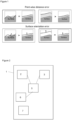
- Figure 1 illustrates point-wise distance error and surface orientation errors. Depth estimations are indicated by surfaces.
- the top row illustrates that point-wise distance error statistics can distinguish between distances to camera sensor (top right) and yet give little information with regard to distinguishing between differing surface normal orientations (top left). ToF sensors are sensitive to this type of depth estimation error.
- the bottom row illustrates that surface orientation error statistics (bottom left) allow to distinguish between normal direction differences yet find it difficult to disambiguate camera sensor distance differences (bottom right). Polarisation sensors are more sensitive to this type of depth estimation error.
- depth sensing is one of the fundamental challenges of computer vision.
- a large set of applications may be enabled by accurate scene depth estimation.
- a depth estimation device (and technique) that is robust, accurate, and real time would be a useful enabling component in these applications.
- strategies involving sensor fusion can be utilized towards improving depth estimation i.e. the combination of multiple, complementary signal sources for improvements to depth estimation accuracy.
- an image processing apparatus configured to estimate a depth field over a field of view
- the apparatus comprising one or more processors configured to: receive a captured polarisation image representing a polarisation of light received at a first set of multiple locations over the field of view; process the captured polarisation image using a first trained neural network to form a first estimate of depths to one or more locations over the field of view; receive ranging data representing environmental distances from a datum to one or more locations over the field of view; process the ranging data using a second trained neural network to form a second estimate of depths to a second set of multiple locations over the field of view; form a synthetic polarisation image representing estimates of the polarisation of light received at a third set of multiple locations over the field of view by processing one or both of the first and second estimates of depths using a first analytic formulae; and form synthetic ranging data representing estimates of the environmental distances to one or more locations over the field of view by processing one or both of the first and second estimates of depths using a first analytic
- the synthetic polarisation image and the synthetic ranging data may be compared respectively with the captured polarisation image and the received ranging data. That comparison, for a region of the image, may be used to select either the synthetic ranging data or the received ranging data as representing a depth estimate for that region of the image.
- the first, second and third sets of multiple locations may by the same or different. It is convenient if they all include at a set of points or regions in common since then the data can be readily compared.
- the polarisation image may represent the polarisation of light received for multiple locations over the field of view at one or more predetermined polarisations. This can allow a preferred depth estimate to be selected irrespective of the actual polarisation for light captured from a given part of the field of view.
- the image processing apparatus may comprise an active sensor apparatus for forming the ranging data.
- the active sensor apparatus may comprises a time-of-flight sensor.
- the sensors may be co-located. They may be attached together so as to image the same or overlapping scenes. This can help to achieve commonality between the subject matter of the captured data.
- the apparatus may be configured to form multiple synthetic polarisation images, the synthetic polarisation images being estimated by the first analytic formulae for a plurality of supposed reflectiveness properties. This can allow a preferred depth estimate to be selected irrespective of the actual polarisation for light captured from a given part of the field of view.
- the supposed reflectiveness properties may comprise diffuseness and specularity. This can allow the behaviour of different surfaces to be modelled.
- the apparatus may be configured to form multiple synthetic polarisation images, the synthetic polarisation images being estimated by the first analytic formulae for a plurality of supposed polarisations. This can allow the system to benefit from a camera that captures images at multiple polarisations.
- the apparatus may be configured to form multiple synthetic polarisation images, the synthetic polarisation images being estimated by the first analytic formulae for a plurality of supposed colours. This can allow the system to accommodate different colours of reflected light in the captured image.
- the step of comparing the polarisation image with the synthetic polarisation image may comprise reducing the multiple synthetic polarisation images to the synthetic polarisation image by selecting for each location in the field of view for which multiple of the synthetic polarisation images hold estimated polarisation information, the polarisation information for that location having the smallest estimated error. This can allow a preferred depth estimated to be selected.
- the first analytic formulae may be such as to form the estimates of the distances to multiple locations over the field of view in dependence on the intensity of at least one polarisation image at the respective locations. This can assist in improving the distance estimates.
- the second analytic formulae may be such as to form, for each of multiple locations over the field of view, multiple estimates of the distances to the respective location in dependence on respective phase offsets. This can allow a preferred one of such estimates to be selected.
- the image processing apparatus may comprise a camera for capturing the captured polarisation image. Then an image captured by the camera may be enhanced in dependence on the computations described above.
- the captured polarisation image may comprise stereoscopic polarisation images. This may assist in forming depth information.
- the first and second neural networks may be the same. This can reduce computational complexity and memory requirements.
- the first analytic formula may be such as to calculate polarisation estimates in dependence on a trigonometric function of an angle formed from a first sub-angle calculated in dependence on a normal to a corresponding surface and a second sub-angle representing a candidate polarisation angle. In this way such a formula can apply a model of reflectance behaviour.
- the second analytic formula may be such as to calculate distance estimates in dependence on a trigonometric function of an angle formed from a phase value calculated in dependence on a depth to a corresponding surface. In this way such a formula can apply a model of reflectance behaviour.
- a computer-implemented method for estimating a depth field over a field of view comprising: receiving a captured polarisation image representing a polarisation of light received at a first set of multiple locations over the field of view; processing the captured polarisation image using a first trained neural network to form a first estimate of depths to one or more locations over the field of view; receiving ranging data representing distances from a datum to one or more environmental locations over the field of view; process the ranging data using a second trained neural network to form a second estimate of depths to a second set of multiple locations over the field of view; forming a synthetic polarisation image representing estimates of the polarisation of light received at a third set of multiple locations over the field of view by processing one or both of the first and second estimates of depths using a first analytic formulae; and forming synthetic ranging data representing estimates of the distances to one or more environmental locations over the field of view by processing one or both of the first and second estimates of depths using a first analytic formulae; and
- Figure 2 shows a device for implementing the present system.
- the device is a mobile phone, but it could be any suitable device and/or the functionality described could be divided between multiple separate devices.
- the device of figure 2 comprises a housing 1 which holds the other components.
- a camera 2 and an active depth sensor 3 are attached to the housing. The camera 2 and the sensor 3 are attached so that they image the same or at least overlapping fields of view.
- a processor 5 (there could be more than one processor) is communicatively coupled to the camera and the depth sensor to receive data from them.
- a memory 6 is coupled to the processor. The memory stores in non-transient form code executable by the processor to perform the functions described herein. By having such code available for execution, the processor is adapted from a general-purpose processor so as to perform those functions.
- the device of figure 2 is hand-portable and powered by a battery or other local energy store 7.
- the camera 2 of figure 2 may include an image sensor and optionally some onboard processing capability.
- the active depth sensor may, for example be a ToF sensor. It may also include some onboard processing capability.
- the device of figure 2 may have a transceiver 8 is capable of communicating over a network with other entities. Those entities may be physically remote from the camera device of figure 2 .
- the network may be a publicly accessible network such as the internet.
- the other entities may be based in the cloud.
- These entities are logical entities. In practice they may each be provided by one or more physical devices such as servers and datastores, and the functions of two or more of the entities may be provided by a single physical device.
- Each physical device implementing such an entity comprises a processor and a memory.
- the devices may also each comprise a transceiver for transmitting and receiving data to and from the transceiver 8 of the device of figure 2 .
- Each memory stores in a non-transient way code that is executable by the respective processor to implement the respective entity in a suitable manner.
- processing is to be performed for the benefit of the device of figure 2 , that processing may be done exclusively at that device, or it may be offloaded in whole or in part to the other entities described above.
- a learning-based pipeline is capable of combining multiple information sources towards recovering scene depth estimations. It has been found that this architecture can provide improved accuracy over the case where estimations from single modalities are used.
- Depth information obtained from imagery can be intrinsically composed of information that indicates (1) surface orientations and (2) point-wise distances to the sensor that captured the image. The location of such a sensor at the time an image is captured may be considered a datum for the estimation of depths in the image.
- the approach to be described below fuses information from multiple modalities. It is desirable to exploiting individual sensor strengths and obtain consistent information from component parts.
- depth estimation is performed using a learning-based strategy involving self-supervised consistency data from multiple modalities.
- the system combines information from multiple image modalities.
- those modalities are (1) directly measured depth data from a time-of-flight (I-ToF) sensor and (2) polarisation data derived from a visual image.
- the framework to be described below can learn (or be provided with a learned) model for depth estimation.
- the learning for such a model may be based on the concept that input signals represent a consistent external world and must therefore be consistent between image modalities.
- the depth values for a part of the image, for instance are all the same, they represent a plane and normals extracted in this area need to be similar. This has been found to result in a method capable of estimating depth, trained using multiple image sources yet requiring only a single modality at inference time.
- An end-to-end pipeline for this purpose is trainable without the need for ground-truth annotation labels by training with a signal that utilizes consistencies in space, time and physical models.
- the resulting model may take advantage of stereo, temporal signals and data from differing modalities such as ToF and polarisation imagery.
- ToF data is often sharp at close range and can provide reliable information in terms of absolute depth distances between scene surface (target) and camera sensor (datum). Active sensors are relatively accurate in such scenarios, as there is no correspondence matching requirement.
- polarisation data while also sharp, is not necessarily as accurate in this regard. Nevertheless, using the approach to be described below polarisation data can provide benefit in terms of correctly identifying surface normal orientation.
- Self-supervision strategies can be extended to multiple image modalities.
- image modalities e.g. polarisation, ToF
- the present model makes use of an autoencoder style architecture with individual decoder network heads for the tasks of depth and surface normal prediction.
- an analytical (derivative) conversion from predicted depth to surface normal intra-modality-task-head consistency can be enforced.
- Inter-modality-output-consistency is also ensured by comparing and penalizing lack of (1) depth prediction agreement (2) surface normal prediction agreement between polarisation and ToF image network outputs.
- (Self-)supervision is obtained using left, right stereo image pairs with left-right consistency checks between image reprojections.
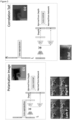
- Figure 3 represents an overview of a model for performing the present processing.
- the model inputs are either ToF correlation or polarisation images and the outputs are depth and normal maps.
- the architecture is composed of a traditional 'U-net' (See Ronneberger, O., Fischer, P. and Brox, T., 2015, October. U-net: Convolutional networks for biomedical image segmentation. In International Conference on Medical image computing and computer-assisted intervention (pp. 234-241). Springer, Ch am.) with skip connections.
- the encoder component utilises a 'Resnet' (see He, K., Zhang, X., Ren, S. and Sun, J., 2016. Deep residual learning for image recognition. In Proceedings of the IEEE conference on computer vision and pattern recognition (pp.
- the decoder is a cascade of convolutions with layer resizing.
- the depth is analytically transformed (e.g. using a cross product of the image derivatives in x and y directions at each location) in order to form a second normal image. The two normal images are then used at training time to enforce consistency, while the depth is the output (final product).
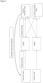
- Figure 4 represents how two of these U-Net architectures can be combined together.
- analytic formulae e.g. see below
- These predicted inputs are then compared to the actual input to help guide the network to predict a more accurate depth. So for example, the network taking ToF as input and returning a depth is guided with a predicted ToF from the predicted depth of ToF as well as a predicted ToF from the predicted depth of polarisation (and vice versa).
- Analytic formulae are used to (i) estimate synthetic depth data from measured polarisation data (in the form of one or more images, which may be captured with polarisation filters at appropriate angles) and (ii) estimate synthetic polarisation data from measured depth data. Then the synthetic polarisation data can be compared with the measured polarisation data and the synthetic depth data can be compared with the measured depth data. Multiple regions of the relevant field of view can be identified. For each such region a selection can be made based on that comparison as to the most internally consistent source of depth data, and the depth as indicated by that source can be treated as the depth for the respective region. Alternatively, another means of fusing the data from the multiple sources may be used, for example by a simple average, by selecting a value most consistent with neighbouring regions or by using other information in the image such as brightness.
- a first analytic formula can be used to form synthetic polarisation data from measured or estimated depth data.
- i ⁇ pol i un 1 + ⁇ cos 2 ⁇ pol ⁇ 2 ⁇ ⁇ pol ⁇ 0 , ⁇ / 2 , ⁇ , 2 ⁇ / 3
- ⁇ pol represents the angle of polarization
- i un is the intensity of unpolarized light
- ⁇ is the degree of linear polarization
- ⁇ is the phase angle
- ⁇ ⁇ 0 ⁇ 2 is the viewing angle and ⁇ the refractive index of the object
- Equation (1) is unchanged when ⁇ is added to ⁇ .
- c x and c y are the image centre's coordinates and Z is the estimated depth map.
- Indirect Time-of-flight sensor measure the correlation between a known signal sent and the measured signal received.
- Equation 6 gives four images over all values of i.
- To train a suitable neural network to implement the present system training data can be formed with an input format comprising: video-rate I-ToF and stereo polarisation (synchronized) imaging sources.
- a proof-of-concept implementation embodiment was constructed. It had a hardware camera rig to test the proposed training and inference ideas with real-world (indoor, outdoor) image data.
- the hardware rig consisted of polarisation stereo cameras, a time-of-flight (ToF) sensor and a structured light active sensor. It was capable of capturing 1280x720 depth images (from the active sensor), 2448x2048 colour polarisation raw image (x 2), 4x640x480 8bit correlation images (ToF).
- Image capture modalities are synchronized using a hardware trigger such that one master camera triggers the others with its exposure active electric flank and this allows data to be captured at circa ten frames per second. Additional manual controls are available for camera rig exposure, gain, focus and aperture settings.
Landscapes
- Engineering & Computer Science (AREA)
- Physics & Mathematics (AREA)
- Theoretical Computer Science (AREA)
- General Physics & Mathematics (AREA)
- Computer Vision & Pattern Recognition (AREA)
- Evolutionary Computation (AREA)
- Computing Systems (AREA)
- Artificial Intelligence (AREA)
- Health & Medical Sciences (AREA)
- Databases & Information Systems (AREA)
- General Health & Medical Sciences (AREA)
- Medical Informatics (AREA)
- Software Systems (AREA)
- Multimedia (AREA)
- Optics & Photonics (AREA)
- Image Analysis (AREA)
- Length Measuring Devices By Optical Means (AREA)
Description
- This invention relates to estimating depth in a scene. The scene may be represented in a visual image. The process of estimating depth may be implemented by using data from a visual image and additionally data representing depth at least some locations in the scene. The scene may fall in the fields of view of one or more sensors.
- A large body of work has been done in the field of computer vision to develop systems capable of estimating depth at locations in a visual image. For example, by recognizing features in an image, a suitably trained neural network can estimate the distance from a datum (e.g. the location of the camera that captured the image) to the location of an item depicted at a location in the image. Another field of research is in sensor devices for directly estimating depth, for example by emitting a signal in a selected direction and estimating the time taken for that signal to return. Each approach relies on some known information in order to extrapolate depth information. The quantity that is known is what differentiates the various sensor device approaches. Examples of known information include the spatial distance between pairs of sensors (stereo), a known light pattern (coded or structured light) and the speed of light (LiDAR, time-of-flight measurement). In each case, the known variable is used in order to estimate depth, e.g. the distance to locations in the image for which no depth data is known a priori.
- A common way to subdivide depth estimation methods is to distinguish between so-called passive methods and so-called active methods. Passive methods typically retrieve depth information from visible spectrum images and consider two-view images (space, 'stereo'), multi-view images (again 'stereo' or time, 'temporal') in order to perform image correspondence matching and triangulation/trilateration. Stereo depth cameras exist which have two sensors spaced typically a small distance apart, a system can compare two images from these sensors which image the same or at least overlapping fields of view. Since the distance between the sensors that capture the images is known, these comparisons can provide depth information.
- An image from a single point of view allows the distance up to a line to be determined. With an image from a second point of view the correct distance to other locations can be inferred by comparing the image content. The maximum distance that stereo setups can reliably measure is directly related to how far apart the two sensors are. The wider the baseline is, the further the system can infer distance with reliability. The distance error quadratically increases with the distance. The field of stereo techniques has been well studied for several decades and is still an active area of research however inherent problems remain that hinder practical applications. These include the requirement of accurate image rectification (i.e. computationally arriving at co-planar and horizontally aligned image planes) and the ill-posed nature of performing correspondence matching in textureless regions of the scene (regions of the image space).
- Another form of depth estimation is to use time-of-flight. This is known as an active method. Light is projected into the scene and depth information can then be measured from the echoed signals. Time-of-flight (ToF) based techniques can be considered a recent approach in active depth sensing. ToF cameras determine depth information by measuring phase differences between the emitted light and the reflected light or the time required by the light for a round-trip from illumination source into the scene and back. ToF devices are typically faster than comparable laser range scanners and are cable of capturing depth information for dynamic scenes in real time. Indirect ToF measurements: where the illumination source and the receiving sensor are not spatially incident; are often relatively noisy and subject to low image resolutions (e.g. 200x200 pixels) in comparison to consumer and high-end visible spectrum, passive cameras (which may have a resolution of multiple megapixels). Depending on the power and wavelength of the light, time-of-flight sensors can measure depth at significant distances. LiDAR sensors make use of knowledge of the speed of light and are essentially time-of-flight cameras which use laser light to perform the depth calculation. Laser range scanner devices constitute the earliest active methods and typically achieve high accuracy. However the slice-by-slice nature of laser scanning makes them time-consuming and generally inapplicable for dynamic scenes. Similar to other ToF cameras, these devices emit a beam of light and sweep the beam over the scene in order to measure the amount of time it takes for the light to return to a sensor on the camera. One disadvantage of time of (low-power) flight cameras is that they are susceptible to other cameras in the same space and may function poorly in outdoor conditions. Strong performance in outdoor conditions requires much higher energy and yet only typically provides a sparse depth signal. If situations can arise where the light registering on the sensor may not have been the light emitted from the specific related camera (e.g. from some other source such as the sun or another camera) this will be detrimental to the quality of resulting depth estimation. The most significant source of error in direct ToF is often attributed to MPI (multi-path interference), i.e. cases where the light is emitted from the correct (original) source but is measured after multiple bounces from within the scene, heavily effecting the distance measurement.
- A further category of active sensor is based on the principals of structured-light or coded-light. These rely on projecting light patterns, typically from a non-visible part of the spectrum (e.g. infrared), into the scene using a light emitter device. The projected pattern is either visual, temporal or a combination of these. Since the projected light constitutes a pattern known to the device, the nature in which the camera sensor perceives the pattern in the scene provides depth information. Using the disparity between an expected image pattern and the actual image (as viewed by the camera) allows calculation of distance to the camera sensor at every pixel (a dense 'depth map'). Structured-light sensors can now be considered a reasonably mature technology with commodity hardware available and a range of consumer devices on the market. The technology relies on accurately capturing light, projected into the scene, and therefore devices do best indoors at relatively short ranges (subject to the power of light emission). Performance may also suffer if there is additional noise in the environment from other cameras or devices emitting light in common parts of the spectrum (e.g. infrared). Depth maps generated by these sensors may also contain holes due to occlusions caused by the relative displacement between the light projection source and the (infrared) camera observing the light.
- In addition to intensity, speed and colour (wavelength), one further source of light information that has been less widely considered for the task of photometric recovery of depth is light polarisation. Light polarisation is affected by factors in a scene such as surface shape, surface curvature, surface material and the position of objects with respect to light sources. Polarisation therefore provides an additional information signal about surface geometry and scene depth. In particular, polarisation imaging can be used for the shape determination of specular and transparent objects, where intensity and wavelength of reflections are less well defined (for example transparent objects will take on the colour of whatever is behind them). The base assumption is that the scene is illuminated by unpolarised light and therefore any polarisation detected can be assumed to be caused by reflection from surfaces. The related assumption is that observed objects have smooth reflective surfaces. By measuring the degree of polarisation of light incident to a camera, the direction of surface normals can be obtained and acquisition of such surface normals at a sufficient number of points in the scene then allows for reconstruction of scene surfaces. The nature of the signal provided by polarisation cameras make for reliable information in terms of physical retrieval of surface normal orientations and can typically afford contrast enhancement and reflection removal. However, the modality is susceptible to surface point-wise absolute distance errors.
- Active range sensors are often utilized in applications where estimation accuracy and robustness is of high importance e.g. robotics and other autonomous systems. However many factors make it infeasible to rely solely on expensive active sensors in every scenario, namely; scene geometry constraints, size, power (active illumination), heat dissipation, expected life / duration of passive vs. active element. Contemporary learning-based approaches have been used in conjunction with many input modalities however reasonable performance can now be achieved by methods that rely on solely passive sensor input. Models typically consider RGB images (monocular or stereo) as input and harness recent learning strategies. Recent work makes use of fully-supervised convolutional neural networks (CNNs) to infer depth from passive stereo image pairs (see Žbontar, J. and LeCun, Y., 2016. Stereo matching by training a convolutional neural network to compare image patches. The journal of machine learning research, 17(1), pp.2287-2318 and Khamis, S., Fanello, S., Rhemann, C., Kowdle, A., Valentin, J. and Izadi, S., 2018. Stereonet: Guided hierarchical refinement for real-time edge-aware depth prediction. In Proceedings of the European Conference on Computer Vision (ECCV) (pp. 573-590)) or even monocular imagery (see Godard, C., Mac Aodha, O. and Brostow, G.J., 2017. Unsupervised monocular depth estimation with left-right consistency. In Proceedings of the IEEE Conference on Computer Vision and Pattern Recognition (pp. 270-279) and Godard C, Mac Aodha O, Firman M, Brostow GJ. Digging into self-supervised monocular depth estimation. In Proceedings of the IEEE international conference on computer vision 2019 (pp. 3828-3838)) where prior knowledge and information about the structure of the world is encoded in (learned) model weights.
- Prior work that combine visual modalities also exist. Recent stereo camera setups (discussed previously) may also have an 'active' component and project infrared light into the scene, towards further improving depth estimation accuracy. In contrast with structured or coded light cameras, stereo cameras may use any part of the light spectrum to measure depth. Since these setups use any visual features to measure depth they are capable of working in most lighting conditions, including outdoors. The addition of an infrared emitter allows such setups to also function in low light conditions as the camera is able to still perceive depth detail (see Zhang, Y., Khamis, S., Rhemann, C., Valentin, J., Kowdle, A., Tankovich, V., Schoenberg, M., Izadi, S., Funkhouser, T. and Fanello, S., 2018. Activestereonet: End-to-end self-supervised learning for active stereo systems. In Proceedings of the European Conference on Computer Vision (ECCV) (pp. 784-801)).
-
Figure 1 illustrates point-wise distance error and surface orientation errors. Depth estimations are indicated by surfaces. The top row illustrates that point-wise distance error statistics can distinguish between distances to camera sensor (top right) and yet give little information with regard to distinguishing between differing surface normal orientations (top left). ToF sensors are sensitive to this type of depth estimation error. The bottom row illustrates that surface orientation error statistics (bottom left) allow to distinguish between normal direction differences yet find it difficult to disambiguate camera sensor distance differences (bottom right). Polarisation sensors are more sensitive to this type of depth estimation error. - In summary, depth sensing is one of the fundamental challenges of computer vision. A large set of applications may be enabled by accurate scene depth estimation. A depth estimation device (and technique) that is robust, accurate, and real time would be a useful enabling component in these applications.
- Existing approaches typically suffer from problems as follows. Laser scanners are too slow for real time use. Passive stereo fails on textureless scenes. Time-of-flight sensors provide real time independent estimates at each pixel however are typically of low resolution, noisy, and poorly calibrated. Photometric stereo is prone to low frequency distortions and polarisation cues may struggle to obtain accurate absolute distances.
- Marc Blanchon et al., 2020. P2D: a self-supervised method for depth estimation from polarimetry. On ARXIV.org, discloses an input of two motion stereo images from which a yellow PoseCNN determines transform parameters between the two images, which are used to form a synthetic input image to calculate a photometric reprojection error for training loss.
- When multiple modalities are available to capture a common scene, strategies involving sensor fusion can be utilized towards improving depth estimation i.e. the combination of multiple, complementary signal sources for improvements to depth estimation accuracy.
- According to one aspect there is provided an image processing apparatus configured to estimate a depth field over a field of view, the apparatus comprising one or more processors configured to: receive a captured polarisation image representing a polarisation of light received at a first set of multiple locations over the field of view; process the captured polarisation image using a first trained neural network to form a first estimate of depths to one or more locations over the field of view; receive ranging data representing environmental distances from a datum to one or more locations over the field of view; process the ranging data using a second trained neural network to form a second estimate of depths to a second set of multiple locations over the field of view; form a synthetic polarisation image representing estimates of the polarisation of light received at a third set of multiple locations over the field of view by processing one or both of the first and second estimates of depths using a first analytic formulae; and form synthetic ranging data representing estimates of the environmental distances to one or more locations over the field of view by processing one or both of the first and second estimates of depths using a second analytic formulae.
- The use of analytic formulae, as opposed to other approaches such as machine learning / neural network approaches to form the synthetic data can reduce the computational complexity of the respective tasks. This can make them more readily implemented on a small device.
- Once the synthetic polarisation image and the synthetic ranging data have been formed, they may be compared respectively with the captured polarisation image and the received ranging data. That comparison, for a region of the image, may be used to select either the synthetic ranging data or the received ranging data as representing a depth estimate for that region of the image.
- The first, second and third sets of multiple locations may by the same or different. It is convenient if they all include at a set of points or regions in common since then the data can be readily compared.
- The polarisation image may represent the polarisation of light received for multiple locations over the field of view at one or more predetermined polarisations. This can allow a preferred depth estimate to be selected irrespective of the actual polarisation for light captured from a given part of the field of view.
- The image processing apparatus may comprise an active sensor apparatus for forming the ranging data. The active sensor apparatus may comprises a time-of-flight sensor. The sensors may be co-located. They may be attached together so as to image the same or overlapping scenes. This can help to achieve commonality between the subject matter of the captured data.
- The apparatus may be configured to form multiple synthetic polarisation images, the synthetic polarisation images being estimated by the first analytic formulae for a plurality of supposed reflectiveness properties. This can allow a preferred depth estimate to be selected irrespective of the actual polarisation for light captured from a given part of the field of view.
- The supposed reflectiveness properties may comprise diffuseness and specularity. This can allow the behaviour of different surfaces to be modelled.
- The apparatus may be configured to form multiple synthetic polarisation images, the synthetic polarisation images being estimated by the first analytic formulae for a plurality of supposed polarisations. This can allow the system to benefit from a camera that captures images at multiple polarisations.
- The apparatus may be configured to form multiple synthetic polarisation images, the synthetic polarisation images being estimated by the first analytic formulae for a plurality of supposed colours. This can allow the system to accommodate different colours of reflected light in the captured image.
- The step of comparing the polarisation image with the synthetic polarisation image may comprise reducing the multiple synthetic polarisation images to the synthetic polarisation image by selecting for each location in the field of view for which multiple of the synthetic polarisation images hold estimated polarisation information, the polarisation information for that location having the smallest estimated error. This can allow a preferred depth estimated to be selected.
- The first analytic formulae may be such as to form the estimates of the distances to multiple locations over the field of view in dependence on the intensity of at least one polarisation image at the respective locations. This can assist in improving the distance estimates.
- The second analytic formulae may be such as to form, for each of multiple locations over the field of view, multiple estimates of the distances to the respective location in dependence on respective phase offsets. This can allow a preferred one of such estimates to be selected.
- The image processing apparatus may comprise a camera for capturing the captured polarisation image. Then an image captured by the camera may be enhanced in dependence on the computations described above.
- The captured polarisation image may comprise stereoscopic polarisation images. This may assist in forming depth information.
- The first and second neural networks may be the same. This can reduce computational complexity and memory requirements.
- The first analytic formula may be such as to calculate polarisation estimates in dependence on a trigonometric function of an angle formed from a first sub-angle calculated in dependence on a normal to a corresponding surface and a second sub-angle representing a candidate polarisation angle. In this way such a formula can apply a model of reflectance behaviour.
- The second analytic formula may be such as to calculate distance estimates in dependence on a trigonometric function of an angle formed from a phase value calculated in dependence on a depth to a corresponding surface. In this way such a formula can apply a model of reflectance behaviour.
- According to a second aspect there is provided a computer-implemented method for estimating a depth field over a field of view, the method comprising: receiving a captured polarisation image representing a polarisation of light received at a first set of multiple locations over the field of view; processing the captured polarisation image using a first trained neural network to form a first estimate of depths to one or more locations over the field of view; receiving ranging data representing distances from a datum to one or more environmental locations over the field of view; process the ranging data using a second trained neural network to form a second estimate of depths to a second set of multiple locations over the field of view; forming a synthetic polarisation image representing estimates of the polarisation of light received at a third set of multiple locations over the field of view by processing one or both of the first and second estimates of depths using a first analytic formulae; and forming synthetic ranging data representing estimates of the distances to one or more environmental locations over the field of view by processing one or both of the first and second estimates of depths using a second analytic formulae.
- The present invention will now be described by way of example with reference to the accompanying drawings. In the drawings:
-
Figure 1 illustrates depth estimation techniques. -
Figure 2 is a schematic of a device for performing depth estimation. -
Figure 3 shows a first schematic of a network architecture for depth estimation from polarisation, correlation ToF input image modalities. -
Figure 4 shows a second schematic of a network architecture for depth estimation from polarisation, correlation ToF input image modalities. -
Figure 2 shows a device for implementing the present system. In this example the device is a mobile phone, but it could be any suitable device and/or the functionality described could be divided between multiple separate devices. - The device of
figure 2 comprises ahousing 1 which holds the other components. Acamera 2 and anactive depth sensor 3 are attached to the housing. Thecamera 2 and thesensor 3 are attached so that they image the same or at least overlapping fields of view. A processor 5 (there could be more than one processor) is communicatively coupled to the camera and the depth sensor to receive data from them. Amemory 6 is coupled to the processor. The memory stores in non-transient form code executable by the processor to perform the functions described herein. By having such code available for execution, the processor is adapted from a general-purpose processor so as to perform those functions. The device offigure 2 is hand-portable and powered by a battery or otherlocal energy store 7. - The
camera 2 offigure 2 may include an image sensor and optionally some onboard processing capability. The active depth sensor may, for example be a ToF sensor. It may also include some onboard processing capability. - The device of
figure 2 may have a transceiver 8 is capable of communicating over a network with other entities. Those entities may be physically remote from the camera device offigure 2 . The network may be a publicly accessible network such as the internet. The other entities may be based in the cloud. These entities are logical entities. In practice they may each be provided by one or more physical devices such as servers and datastores, and the functions of two or more of the entities may be provided by a single physical device. Each physical device implementing such an entity comprises a processor and a memory. The devices may also each comprise a transceiver for transmitting and receiving data to and from the transceiver 8 of the device offigure 2 . Each memory stores in a non-transient way code that is executable by the respective processor to implement the respective entity in a suitable manner. - Where processing is to be performed for the benefit of the device of
figure 2 , that processing may be done exclusively at that device, or it may be offloaded in whole or in part to the other entities described above. - The system to be described below can estimate scene depth from multiple visual information sources. A learning-based pipeline is capable of combining multiple information sources towards recovering scene depth estimations. It has been found that this architecture can provide improved accuracy over the case where estimations from single modalities are used.
- Depth information obtained from imagery can be intrinsically composed of information that indicates (1) surface orientations and (2) point-wise distances to the sensor that captured the image. The location of such a sensor at the time an image is captured may be considered a datum for the estimation of depths in the image. The approach to be described below fuses information from multiple modalities. It is desirable to exploiting individual sensor strengths and obtain consistent information from component parts.
- In the present system depth estimation is performed using a learning-based strategy involving self-supervised consistency data from multiple modalities. The system combines information from multiple image modalities. In the example to be described below those modalities are (1) directly measured depth data from a time-of-flight (I-ToF) sensor and (2) polarisation data derived from a visual image. The framework to be described below can learn (or be provided with a learned) model for depth estimation. The learning for such a model may be based on the concept that input signals represent a consistent external world and must therefore be consistent between image modalities. Thus, if the depth values for a part of the image, for instance, are all the same, they represent a plane and normals extracted in this area need to be similar. This has been found to result in a method capable of estimating depth, trained using multiple image sources yet requiring only a single modality at inference time.
- An end-to-end pipeline for this purpose is trainable without the need for ground-truth annotation labels by training with a signal that utilizes consistencies in space, time and physical models. The resulting model may take advantage of stereo, temporal signals and data from differing modalities such as ToF and polarisation imagery. For a specific example, it can be observed that ToF data is often sharp at close range and can provide reliable information in terms of absolute depth distances between scene surface (target) and camera sensor (datum). Active sensors are relatively accurate in such scenarios, as there is no correspondence matching requirement. In contrast, it has been noted that polarisation data, while also sharp, is not necessarily as accurate in this regard. Nevertheless, using the approach to be described below polarisation data can provide benefit in terms of correctly identifying surface normal orientation. Using this modality affords information of the polarisation state of diffusely reflected light which in turn allows to establish correspondences on featureless surfaces enabling stereo-based surface recovery in typically challenging settings. The present learning-based strategy allows to implicitly harness the differing advantages of the modalities (short range, long range). Learning under multiple modalities offers quality improvements also for single individual modalities.
- Learning-based methods are now able to obtain depth estimation via single RGB images, however, a large set of existing approaches treat depth prediction as a supervised regression problem and thus require large quantities of corresponding ground-truth data for model training. Obtaining high quality depth data in a range of environments, to serve as ground-truth labels, can be considered prohibitively expensive and is often infeasible. As an alternative to the challenging task of collecting ground-truth depth data, in a range of environments, self-supervised approaches have recently been proposed, negating the requirement for labels per pixel. Self-supervised training signals are then defined using (easier-to-obtain) binocular stereo footage or monocular video and the definition of an appropriate image reconstruction training loss. In this fashion, self-supervised losses can either be constructed using (1) two sensors or (2) a cyclic style reconstruction approach where the original input data may be considered for comparison with a reconstruction thereof.
- Self-supervision strategies can be extended to multiple image modalities. For each of a set of considered image modalities (e.g. polarisation, ToF) the present model makes use of an autoencoder style architecture with individual decoder network heads for the tasks of depth and surface normal prediction. By using an analytical (derivative) conversion from predicted depth to surface normal intra-modality-task-head consistency can be enforced. Inter-modality-output-consistency is also ensured by comparing and penalizing lack of (1) depth prediction agreement (2) surface normal prediction agreement between polarisation and ToF image network outputs. (Self-)supervision is obtained using left, right stereo image pairs with left-right consistency checks between image reprojections. This allows to train the models with geometric consistencies, yet without the need for ground-truth labels. The adaptation of self-supervised spatial consistency leverages the second sensor and an adaptation of self-supervised temporal consistency leverages video data. In summary, the intrinsic properties of the modalities (polarisation, ToF) used in conjunction improve estimation of distance and geometry with formulation of a model of physical consistencies for learning. This allows us to define an identical model learning strategy for each (both) image modalities. It can be noted that specular and diffuse masks are also determined as a biproduct of the polarisation process.
Figure 3 provides an overview schematic of the present model architecture.Figure 4 describes how multiple architectures can be combined. -
Figure 3 represents an overview of a model for performing the present processing. The model inputs are either ToF correlation or polarisation images and the outputs are depth and normal maps. The architecture is composed of a traditional 'U-net' (See Ronneberger, O., Fischer, P. and Brox, T., 2015, October. U-net: Convolutional networks for biomedical image segmentation. In International Conference on Medical image computing and computer-assisted intervention (pp. 234-241). Springer, Cham.) with skip connections. The encoder component utilises a 'Resnet' (see He, K., Zhang, X., Ren, S. and Sun, J., 2016. Deep residual learning for image recognition. In Proceedings of the IEEE conference on computer vision and pattern recognition (pp. 770-778)) style block while the decoder is a cascade of convolutions with layer resizing. There are two decoders for each encoder. Each decoder outputs a different target; one for the depth image, the other for the normal image. Finally, the depth is analytically transformed (e.g. using a cross product of the image derivatives in x and y directions at each location) in order to form a second normal image. The two normal images are then used at training time to enforce consistency, while the depth is the output (final product). -
Figure 4 represents how two of these U-Net architectures can be combined together. Using the analytic formulae (e.g. see below), one can form a prediction of the input (either ToF or polarisation) from the predicted depth. These predicted inputs are then compared to the actual input to help guide the network to predict a more accurate depth. So for example, the network taking ToF as input and returning a depth is guided with a predicted ToF from the predicted depth of ToF as well as a predicted ToF from the predicted depth of polarisation (and vice versa). - Analytic formulae are used to (i) estimate synthetic depth data from measured polarisation data (in the form of one or more images, which may be captured with polarisation filters at appropriate angles) and (ii) estimate synthetic polarisation data from measured depth data. Then the synthetic polarisation data can be compared with the measured polarisation data and the synthetic depth data can be compared with the measured depth data. Multiple regions of the relevant field of view can be identified. For each such region a selection can be made based on that comparison as to the most internally consistent source of depth data, and the depth as indicated by that source can be treated as the depth for the respective region. Alternatively, another means of fusing the data from the multiple sources may be used, for example by a simple average, by selecting a value most consistent with neighbouring regions or by using other information in the image such as brightness.
- A first analytic formula can be used to form synthetic polarisation data from measured or estimated depth data.
- Most light sources emit unpolarized light. Light becomes polarized when it is reflected on objects. Polarization cameras capture polarized intensity along various direction ϕ pol such as:
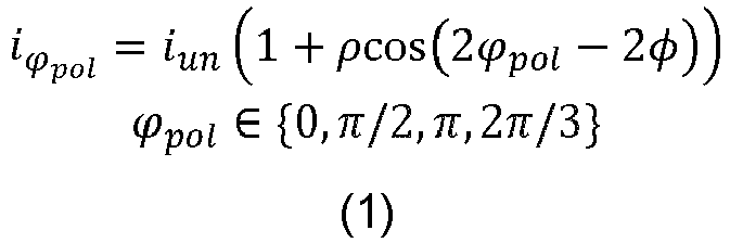
- Where ϕ pol represents the angle of polarization, iun is the intensity of unpolarized light, ρ is the degree of linear polarization and φ is the phase angle.
- The polarization parameters ρ and φ come either from a diffuse surface (d) or a specular surface (s) as follows:

- Where


- Where α is the azimuth angle of the normal
n . Note that the π-ambiguity comes from the fact that Equation (1) is unchanged when π is added to φ. - Finally the azimuth angle α and the viewing angle θ are obtained as:

- Where the viewing vector
v pointing towards the camera's centre from the considered point are obtained as:
- Where cx and cy are the image centre's coordinates and Z is the estimated depth map.
- Indirect Time-of-flight sensor measure the correlation between a known signal sent and the measured signal received. Using a four-bucket sampling strategy, we can recover the distance from the sensor to an object. The four correlation measurements are modeled as:

- Where A is the amplitude, I the intensity, and φ the difference of phase between the emitted signal and the received:

-
Equation 6 gives four images over all values of i. - When comparing the synthetic and measured depth and polarisation data a selection can be made as to the best of each of the 24 images from the first formula and the best four images from the second formula for consistency.
- To train a suitable neural network to implement the present system training data can be formed with an input format comprising: video-rate I-ToF and stereo polarisation (synchronized) imaging sources. Towards obtaining such data a proof-of-concept implementation embodiment was constructed. It had a hardware camera rig to test the proposed training and inference ideas with real-world (indoor, outdoor) image data. The hardware rig consisted of polarisation stereo cameras, a time-of-flight (ToF) sensor and a structured light active sensor. It was capable of capturing 1280x720 depth images (from the active sensor), 2448x2048 colour polarisation raw image (x 2), 4x640x480 8bit correlation images (ToF). Image capture modalities are synchronized using a hardware trigger such that one master camera triggers the others with its exposure active electric flank and this allows data to be captured at circa ten frames per second. Additional manual controls are available for camera rig exposure, gain, focus and aperture settings.
Claims (15)
- Image processing apparatus configured to estimate a depth field over a field of view, the apparatus comprising one or more processors (5) configured to:receive a captured polarisation image representing a polarisation of light received at a first set of multiple locations over the field of view;process the captured polarisation image using a first trained neural network to form a first estimate of depths to one or more locations over the field of view;receive ranging data representing environmental distances from a datum to one or more locations over the field of view;process the ranging data using a second trained neural network to form a second estimate of depths to a second set of multiple locations over the field of view;form a synthetic polarisation image representing estimates of the polarisation of light received at a third set of multiple locations over the field of view by processing one or both of the first and second estimates of depths using a first analytic formulae; andform synthetic ranging data representing estimates of the environmental distances to one or more locations over the field of view by processing one or both of the first and second estimates of depths using a second analytic formulae.
- An image processing apparatus as claimed in claim 1, wherein the polarisation image represents the polarisation of light received for multiple locations over the field of view at one or more predetermined polarisations.
- An image processing apparatus as claimed in claim 1 or 2, wherein the image processing apparatus comprises an active sensor apparatus (3) for forming the ranging data and the active sensor apparatus comprises a time-of-flight sensor.
- An image processing apparatus as claimed in any preceding claim, the apparatus being configured to form multiple synthetic polarisation images, the synthetic polarisation images being estimated by the first analytic formulae for a plurality of supposed reflectiveness properties.
- An image processing apparatus as claimed in claim 4, wherein the supposed reflectiveness properties comprise diffuseness and specularity.
- An image processing apparatus as claimed in any preceding claim, the apparatus being configured to form multiple synthetic polarisation images, the synthetic polarisation images being estimated by the first analytic formulae for a plurality of supposed polarisations.
- An image processing apparatus as claimed in any preceding claim, the apparatus being configured to form multiple synthetic polarisation images, the synthetic polarisation images being estimated by the first analytic formulae for a plurality of supposed colours.
- An image processing apparatus as claimed in any of claims 4 to 7, wherein a step of comparing the polarisation image with the synthetic polarisation image comprises reducing the multiple synthetic polarisation images to the synthetic polarisation image by selecting for each location in the field of view for which multiple of the synthetic polarisation images hold estimated polarisation information, the polarisation information for that location having the smallest estimated error.
- An image processing apparatus as claimed in any preceding claim, wherein the first analytic formulae are such as to form the estimates of the distances to multiple locations over the field of view in dependence on the intensity of at least one polarisation image at the respective locations.
- An image processing apparatus as claimed in any preceding claim, wherein the second analytic formulae are such as to form, for each of multiple locations over the field of view, multiple estimates of the distances to the respective location in dependence on respective phase offsets.
- An image processing apparatus as claimed in any preceding claim, wherein the image processing apparatus comprises a camera (2) for capturing the captured polarisation image.
- An image processing apparatus as claimed in any preceding claim, wherein the captured polarisation image comprises stereoscopic polarisation images.
- An image processing apparatus as claimed in any preceding claim, wherein the first analytic formula is such as to calculate polarisation estimates in dependence on a trigonometric function of an angle formed from a first sub-angle calculated in dependence on a normal to a corresponding surface and a second sub-angle representing a candidate polarisation angle.
- An image processing apparatus as claimed in any preceding claim, wherein the second analytic formula is such as to calculate distance estimates in dependence on a trigonometric function of an angle formed from a phase value calculated in dependence on a depth to a corresponding surface.
- A computer-implemented method for estimating a depth field over a field of view, the method comprising:receiving a captured polarisation image representing a polarisation of light received at a first set of multiple locations over the field of view;processing the captured polarisation image using a first trained neural network to form a first estimate of depths to one or more locations over the field of view;receiving ranging data representing distances from a datum to one or more environmental locations over the field of view;process the ranging data using a second trained neural network to form a second estimate of depths to a second set of multiple locations over the field of view;forming a synthetic polarisation image representing estimates of the polarisation of light received at a third set of multiple locations over the field of view by processing one or both of the first and second estimates of depths using a first analytic formulae; andforming synthetic ranging data representing estimates of the distances to one or more environmental locations over the field of view by processing one or both of the first and second estimates of depths using a second analytic formulae.
Applications Claiming Priority (1)
| Application Number | Priority Date | Filing Date | Title |
|---|---|---|---|
| PCT/EP2020/081385 WO2022096127A1 (en) | 2020-11-06 | 2020-11-06 | A device and method for image processing |
Publications (3)
| Publication Number | Publication Date |
|---|---|
| EP4217962A1 EP4217962A1 (en) | 2023-08-02 |
| EP4217962B1 true EP4217962B1 (en) | 2024-08-28 |
| EP4217962B8 EP4217962B8 (en) | 2024-12-18 |
Family
ID=73172740
Family Applications (1)
| Application Number | Title | Priority Date | Filing Date |
|---|---|---|---|
| EP20803557.6A Active EP4217962B8 (en) | 2020-11-06 | 2020-11-06 | A device and method for image processing |
Country Status (4)
| Country | Link |
|---|---|
| US (1) | US20230273357A1 (en) |
| EP (1) | EP4217962B8 (en) |
| CN (1) | CN115997235B (en) |
| WO (1) | WO2022096127A1 (en) |
Families Citing this family (2)
| Publication number | Priority date | Publication date | Assignee | Title |
|---|---|---|---|---|
| CN116778001B (en) * | 2023-08-24 | 2023-10-13 | 华东交通大学 | Camera-projector calibration method and system based on global optimal polarized image |
| CN119339139B (en) * | 2024-10-08 | 2025-08-29 | 中国科学技术大学 | A target detection method in dark environment |
Family Cites Families (5)
| Publication number | Priority date | Publication date | Assignee | Title |
|---|---|---|---|---|
| WO2017056821A1 (en) * | 2015-09-30 | 2017-04-06 | ソニー株式会社 | Information acquiring device and information acquiring method |
| CN107958446B (en) * | 2016-10-17 | 2023-04-07 | 索尼公司 | Information processing apparatus, information processing method, and computer program |
| JP2019067323A (en) * | 2017-10-05 | 2019-04-25 | ソニー株式会社 | Information processing apparatus, information processing method, and recording medium |
| CN111127384A (en) * | 2018-10-15 | 2020-05-08 | 华东交通大学 | Strong reflection workpiece vision measurement method based on polarization imaging |
| CN111369608A (en) * | 2020-05-29 | 2020-07-03 | 南京晓庄学院 | A Visual Odometry Method Based on Image Depth Estimation |
-
2020
- 2020-11-06 CN CN202080103540.6A patent/CN115997235B/en active Active
- 2020-11-06 EP EP20803557.6A patent/EP4217962B8/en active Active
- 2020-11-06 WO PCT/EP2020/081385 patent/WO2022096127A1/en not_active Ceased
-
2023
- 2023-05-02 US US18/311,086 patent/US20230273357A1/en active Pending
Also Published As
| Publication number | Publication date |
|---|---|
| WO2022096127A1 (en) | 2022-05-12 |
| EP4217962B8 (en) | 2024-12-18 |
| US20230273357A1 (en) | 2023-08-31 |
| CN115997235A (en) | 2023-04-21 |
| EP4217962A1 (en) | 2023-08-02 |
| CN115997235B (en) | 2025-05-27 |
Similar Documents
| Publication | Publication Date | Title |
|---|---|---|
| EP4042101B1 (en) | Systems and methods for surface normals sensing with polarization | |
| US9959455B2 (en) | System and method for face recognition using three dimensions | |
| US12260575B2 (en) | Scale-aware monocular localization and mapping | |
| US9392262B2 (en) | System and method for 3D reconstruction using multiple multi-channel cameras | |
| Serafin et al. | NICP: Dense normal based point cloud registration | |
| Fanello et al. | Hyperdepth: Learning depth from structured light without matching | |
| Chen et al. | Comparative study on 3D optical sensors for short range applications | |
| Taylor et al. | Multi‐modal sensor calibration using a gradient orientation measure | |
| US9501833B2 (en) | Method and system for providing three-dimensional and range inter-planar estimation | |
| US11803982B2 (en) | Image processing device and three-dimensional measuring system | |
| CN103824318A (en) | Multi-camera-array depth perception method | |
| CN113160416B (en) | Speckle imaging device and method for coal flow detection | |
| KR20160121509A (en) | Structured light matching of a set of curves from two cameras | |
| El Bouazzaoui et al. | Enhancing RGB-D SLAM performances considering sensor specifications for indoor localization | |
| US20230273357A1 (en) | Device and method for image processing | |
| O'Byrne et al. | A comparison of image based 3D recovery methods for underwater inspections | |
| Hahne et al. | Depth imaging by combining time-of-flight and on-demand stereo | |
| Nagamatsu et al. | Self-calibrated dense 3d sensor using multiple cross line-lasers based on light sectioning method and visual odometry | |
| Lu et al. | Extending single beam lidar to full resolution by fusing with single image depth estimation | |
| US20240114119A1 (en) | Image processing device, image processing method, and program | |
| Cheng et al. | Structured light-based shape measurement system | |
| US20240095939A1 (en) | Information processing apparatus and information processing method | |
| Lee et al. | Tc-ltio: tightly-coupled lidar thermal inertial odometry for lidar and visual odometry degraded environments | |
| US20230106749A1 (en) | Three-dimensional measurement device | |
| Inglis et al. | Sonar constrained stereo correspondence for three-dimensional seafloor reconstruction |
Legal Events
| Date | Code | Title | Description |
|---|---|---|---|
| STAA | Information on the status of an ep patent application or granted ep patent |
Free format text: STATUS: UNKNOWN |
|
| STAA | Information on the status of an ep patent application or granted ep patent |
Free format text: STATUS: THE INTERNATIONAL PUBLICATION HAS BEEN MADE |
|
| PUAI | Public reference made under article 153(3) epc to a published international application that has entered the european phase |
Free format text: ORIGINAL CODE: 0009012 |
|
| STAA | Information on the status of an ep patent application or granted ep patent |
Free format text: STATUS: REQUEST FOR EXAMINATION WAS MADE |
|
| 17P | Request for examination filed |
Effective date: 20230428 |
|
| AK | Designated contracting states |
Kind code of ref document: A1 Designated state(s): AL AT BE BG CH CY CZ DE DK EE ES FI FR GB GR HR HU IE IS IT LI LT LU LV MC MK MT NL NO PL PT RO RS SE SI SK SM TR |
|
| RIN1 | Information on inventor provided before grant (corrected) |
Inventor name: MAS, BARNABE Inventor name: MCDONAGH, STEVEN, GEORGE Inventor name: BUSAM, BENJAMIN Inventor name: VERDIE, YANNICK |
|
| DAV | Request for validation of the european patent (deleted) | ||
| DAX | Request for extension of the european patent (deleted) | ||
| GRAP | Despatch of communication of intention to grant a patent |
Free format text: ORIGINAL CODE: EPIDOSNIGR1 |
|
| STAA | Information on the status of an ep patent application or granted ep patent |
Free format text: STATUS: GRANT OF PATENT IS INTENDED |
|
| INTG | Intention to grant announced |
Effective date: 20240429 |
|
| GRAS | Grant fee paid |
Free format text: ORIGINAL CODE: EPIDOSNIGR3 |
|
| GRAA | (expected) grant |
Free format text: ORIGINAL CODE: 0009210 |
|
| STAA | Information on the status of an ep patent application or granted ep patent |
Free format text: STATUS: THE PATENT HAS BEEN GRANTED |
|
| AK | Designated contracting states |
Kind code of ref document: B1 Designated state(s): AL AT BE BG CH CY CZ DE DK EE ES FI FR GB GR HR HU IE IS IT LI LT LU LV MC MK MT NL NO PL PT RO RS SE SI SK SM TR |
|
| REG | Reference to a national code |
Ref country code: CH Ref legal event code: EP |
|
| REG | Reference to a national code |
Ref country code: IE Ref legal event code: FG4D |
|
| REG | Reference to a national code |
Ref country code: DE Ref legal event code: R096 Ref document number: 602020036768 Country of ref document: DE |
|
| GRAT | Correction requested after decision to grant or after decision to maintain patent in amended form |
Free format text: ORIGINAL CODE: EPIDOSNCDEC |
|
| REG | Reference to a national code |
Ref country code: CH Ref legal event code: PK Free format text: BERICHTIGUNG B8 Ref country code: CH Ref legal event code: PK Free format text: BERICHTIGUNGEN |
|
| RIN2 | Information on inventor provided after grant (corrected) |
Inventor name: MAS, BARBABE Inventor name: MCDONAGH, STEVEN, GEORGE Inventor name: BUSAM, BENJAMIN Inventor name: VERDIE, YANNICK Inventor name: LEONARDIS, ALES |
|
| REG | Reference to a national code |
Ref country code: LT Ref legal event code: MG9D |
|
| PG25 | Lapsed in a contracting state [announced via postgrant information from national office to epo] |
Ref country code: NO Free format text: LAPSE BECAUSE OF FAILURE TO SUBMIT A TRANSLATION OF THE DESCRIPTION OR TO PAY THE FEE WITHIN THE PRESCRIBED TIME-LIMIT Effective date: 20241128 |
|
| REG | Reference to a national code |
Ref country code: AT Ref legal event code: MK05 Ref document number: 1718812 Country of ref document: AT Kind code of ref document: T Effective date: 20240828 |
|
| PG25 | Lapsed in a contracting state [announced via postgrant information from national office to epo] |
Ref country code: PT Free format text: LAPSE BECAUSE OF FAILURE TO SUBMIT A TRANSLATION OF THE DESCRIPTION OR TO PAY THE FEE WITHIN THE PRESCRIBED TIME-LIMIT Effective date: 20241230 Ref country code: GR Free format text: LAPSE BECAUSE OF FAILURE TO SUBMIT A TRANSLATION OF THE DESCRIPTION OR TO PAY THE FEE WITHIN THE PRESCRIBED TIME-LIMIT Effective date: 20241129 Ref country code: NL Free format text: LAPSE BECAUSE OF FAILURE TO SUBMIT A TRANSLATION OF THE DESCRIPTION OR TO PAY THE FEE WITHIN THE PRESCRIBED TIME-LIMIT Effective date: 20240828 Ref country code: FI Free format text: LAPSE BECAUSE OF FAILURE TO SUBMIT A TRANSLATION OF THE DESCRIPTION OR TO PAY THE FEE WITHIN THE PRESCRIBED TIME-LIMIT Effective date: 20240828 Ref country code: PL Free format text: LAPSE BECAUSE OF FAILURE TO SUBMIT A TRANSLATION OF THE DESCRIPTION OR TO PAY THE FEE WITHIN THE PRESCRIBED TIME-LIMIT Effective date: 20240828 |
|
| PG25 | Lapsed in a contracting state [announced via postgrant information from national office to epo] |
Ref country code: BG Free format text: LAPSE BECAUSE OF FAILURE TO SUBMIT A TRANSLATION OF THE DESCRIPTION OR TO PAY THE FEE WITHIN THE PRESCRIBED TIME-LIMIT Effective date: 20240828 |
|
| PG25 | Lapsed in a contracting state [announced via postgrant information from national office to epo] |
Ref country code: LV Free format text: LAPSE BECAUSE OF FAILURE TO SUBMIT A TRANSLATION OF THE DESCRIPTION OR TO PAY THE FEE WITHIN THE PRESCRIBED TIME-LIMIT Effective date: 20240828 |
|
| REG | Reference to a national code |
Ref country code: NL Ref legal event code: MP Effective date: 20240828 |
|
| PG25 | Lapsed in a contracting state [announced via postgrant information from national office to epo] |
Ref country code: AT Free format text: LAPSE BECAUSE OF FAILURE TO SUBMIT A TRANSLATION OF THE DESCRIPTION OR TO PAY THE FEE WITHIN THE PRESCRIBED TIME-LIMIT Effective date: 20240828 Ref country code: IS Free format text: LAPSE BECAUSE OF FAILURE TO SUBMIT A TRANSLATION OF THE DESCRIPTION OR TO PAY THE FEE WITHIN THE PRESCRIBED TIME-LIMIT Effective date: 20241228 |
|
| PG25 | Lapsed in a contracting state [announced via postgrant information from national office to epo] |
Ref country code: HR Free format text: LAPSE BECAUSE OF FAILURE TO SUBMIT A TRANSLATION OF THE DESCRIPTION OR TO PAY THE FEE WITHIN THE PRESCRIBED TIME-LIMIT Effective date: 20240828 |
|
| PG25 | Lapsed in a contracting state [announced via postgrant information from national office to epo] |
Ref country code: RS Free format text: LAPSE BECAUSE OF FAILURE TO SUBMIT A TRANSLATION OF THE DESCRIPTION OR TO PAY THE FEE WITHIN THE PRESCRIBED TIME-LIMIT Effective date: 20241128 Ref country code: ES Free format text: LAPSE BECAUSE OF FAILURE TO SUBMIT A TRANSLATION OF THE DESCRIPTION OR TO PAY THE FEE WITHIN THE PRESCRIBED TIME-LIMIT Effective date: 20240828 |
|
| PG25 | Lapsed in a contracting state [announced via postgrant information from national office to epo] |
Ref country code: RS Free format text: LAPSE BECAUSE OF FAILURE TO SUBMIT A TRANSLATION OF THE DESCRIPTION OR TO PAY THE FEE WITHIN THE PRESCRIBED TIME-LIMIT Effective date: 20241128 Ref country code: PT Free format text: LAPSE BECAUSE OF FAILURE TO SUBMIT A TRANSLATION OF THE DESCRIPTION OR TO PAY THE FEE WITHIN THE PRESCRIBED TIME-LIMIT Effective date: 20241230 Ref country code: PL Free format text: LAPSE BECAUSE OF FAILURE TO SUBMIT A TRANSLATION OF THE DESCRIPTION OR TO PAY THE FEE WITHIN THE PRESCRIBED TIME-LIMIT Effective date: 20240828 Ref country code: NO Free format text: LAPSE BECAUSE OF FAILURE TO SUBMIT A TRANSLATION OF THE DESCRIPTION OR TO PAY THE FEE WITHIN THE PRESCRIBED TIME-LIMIT Effective date: 20241128 Ref country code: NL Free format text: LAPSE BECAUSE OF FAILURE TO SUBMIT A TRANSLATION OF THE DESCRIPTION OR TO PAY THE FEE WITHIN THE PRESCRIBED TIME-LIMIT Effective date: 20240828 Ref country code: LV Free format text: LAPSE BECAUSE OF FAILURE TO SUBMIT A TRANSLATION OF THE DESCRIPTION OR TO PAY THE FEE WITHIN THE PRESCRIBED TIME-LIMIT Effective date: 20240828 Ref country code: IS Free format text: LAPSE BECAUSE OF FAILURE TO SUBMIT A TRANSLATION OF THE DESCRIPTION OR TO PAY THE FEE WITHIN THE PRESCRIBED TIME-LIMIT Effective date: 20241228 Ref country code: HR Free format text: LAPSE BECAUSE OF FAILURE TO SUBMIT A TRANSLATION OF THE DESCRIPTION OR TO PAY THE FEE WITHIN THE PRESCRIBED TIME-LIMIT Effective date: 20240828 Ref country code: GR Free format text: LAPSE BECAUSE OF FAILURE TO SUBMIT A TRANSLATION OF THE DESCRIPTION OR TO PAY THE FEE WITHIN THE PRESCRIBED TIME-LIMIT Effective date: 20241129 Ref country code: FI Free format text: LAPSE BECAUSE OF FAILURE TO SUBMIT A TRANSLATION OF THE DESCRIPTION OR TO PAY THE FEE WITHIN THE PRESCRIBED TIME-LIMIT Effective date: 20240828 Ref country code: ES Free format text: LAPSE BECAUSE OF FAILURE TO SUBMIT A TRANSLATION OF THE DESCRIPTION OR TO PAY THE FEE WITHIN THE PRESCRIBED TIME-LIMIT Effective date: 20240828 Ref country code: BG Free format text: LAPSE BECAUSE OF FAILURE TO SUBMIT A TRANSLATION OF THE DESCRIPTION OR TO PAY THE FEE WITHIN THE PRESCRIBED TIME-LIMIT Effective date: 20240828 Ref country code: AT Free format text: LAPSE BECAUSE OF FAILURE TO SUBMIT A TRANSLATION OF THE DESCRIPTION OR TO PAY THE FEE WITHIN THE PRESCRIBED TIME-LIMIT Effective date: 20240828 |
|
| PG25 | Lapsed in a contracting state [announced via postgrant information from national office to epo] |
Ref country code: RO Free format text: LAPSE BECAUSE OF FAILURE TO SUBMIT A TRANSLATION OF THE DESCRIPTION OR TO PAY THE FEE WITHIN THE PRESCRIBED TIME-LIMIT Effective date: 20240828 Ref country code: DK Free format text: LAPSE BECAUSE OF FAILURE TO SUBMIT A TRANSLATION OF THE DESCRIPTION OR TO PAY THE FEE WITHIN THE PRESCRIBED TIME-LIMIT Effective date: 20240828 Ref country code: SM Free format text: LAPSE BECAUSE OF FAILURE TO SUBMIT A TRANSLATION OF THE DESCRIPTION OR TO PAY THE FEE WITHIN THE PRESCRIBED TIME-LIMIT Effective date: 20240828 |
|
| PG25 | Lapsed in a contracting state [announced via postgrant information from national office to epo] |
Ref country code: CZ Free format text: LAPSE BECAUSE OF FAILURE TO SUBMIT A TRANSLATION OF THE DESCRIPTION OR TO PAY THE FEE WITHIN THE PRESCRIBED TIME-LIMIT Effective date: 20240828 |
|
| PG25 | Lapsed in a contracting state [announced via postgrant information from national office to epo] |
Ref country code: SK Free format text: LAPSE BECAUSE OF FAILURE TO SUBMIT A TRANSLATION OF THE DESCRIPTION OR TO PAY THE FEE WITHIN THE PRESCRIBED TIME-LIMIT Effective date: 20240828 Ref country code: IT Free format text: LAPSE BECAUSE OF FAILURE TO SUBMIT A TRANSLATION OF THE DESCRIPTION OR TO PAY THE FEE WITHIN THE PRESCRIBED TIME-LIMIT Effective date: 20240828 |
|
| REG | Reference to a national code |
Ref country code: DE Ref legal event code: R097 Ref document number: 602020036768 Country of ref document: DE |
|
| REG | Reference to a national code |
Ref country code: CH Ref legal event code: PL |
|
| PLBE | No opposition filed within time limit |
Free format text: ORIGINAL CODE: 0009261 |
|
| STAA | Information on the status of an ep patent application or granted ep patent |
Free format text: STATUS: NO OPPOSITION FILED WITHIN TIME LIMIT |
|
| PG25 | Lapsed in a contracting state [announced via postgrant information from national office to epo] |
Ref country code: MC Free format text: LAPSE BECAUSE OF FAILURE TO SUBMIT A TRANSLATION OF THE DESCRIPTION OR TO PAY THE FEE WITHIN THE PRESCRIBED TIME-LIMIT Effective date: 20240828 |
|
| PG25 | Lapsed in a contracting state [announced via postgrant information from national office to epo] |
Ref country code: LU Free format text: LAPSE BECAUSE OF NON-PAYMENT OF DUE FEES Effective date: 20241106 |
|
| REG | Reference to a national code |
Ref country code: CH Ref legal event code: PL |
|
| GBPC | Gb: european patent ceased through non-payment of renewal fee |
Effective date: 20241128 |
|
| PG25 | Lapsed in a contracting state [announced via postgrant information from national office to epo] |
Ref country code: CH Free format text: LAPSE BECAUSE OF NON-PAYMENT OF DUE FEES Effective date: 20241130 |
|
| 26N | No opposition filed |
Effective date: 20250530 |
|
| REG | Reference to a national code |
Ref country code: BE Ref legal event code: MM Effective date: 20241130 |
|
| PG25 | Lapsed in a contracting state [announced via postgrant information from national office to epo] |
Ref country code: SE Free format text: LAPSE BECAUSE OF FAILURE TO SUBMIT A TRANSLATION OF THE DESCRIPTION OR TO PAY THE FEE WITHIN THE PRESCRIBED TIME-LIMIT Effective date: 20240828 |
|
| PG25 | Lapsed in a contracting state [announced via postgrant information from national office to epo] |
Ref country code: GB Free format text: LAPSE BECAUSE OF NON-PAYMENT OF DUE FEES Effective date: 20241128 Ref country code: BE Free format text: LAPSE BECAUSE OF NON-PAYMENT OF DUE FEES Effective date: 20241130 |
|
| PG25 | Lapsed in a contracting state [announced via postgrant information from national office to epo] |
Ref country code: FR Free format text: LAPSE BECAUSE OF NON-PAYMENT OF DUE FEES Effective date: 20241130 |
|
| PG25 | Lapsed in a contracting state [announced via postgrant information from national office to epo] |
Ref country code: IE Free format text: LAPSE BECAUSE OF NON-PAYMENT OF DUE FEES Effective date: 20241106 |
|
| PGFP | Annual fee paid to national office [announced via postgrant information from national office to epo] |
Ref country code: DE Payment date: 20250930 Year of fee payment: 6 |
|
| PG25 | Lapsed in a contracting state [announced via postgrant information from national office to epo] |
Ref country code: HU Free format text: LAPSE BECAUSE OF FAILURE TO SUBMIT A TRANSLATION OF THE DESCRIPTION OR TO PAY THE FEE WITHIN THE PRESCRIBED TIME-LIMIT; INVALID AB INITIO Effective date: 20201106 |
|
| PG25 | Lapsed in a contracting state [announced via postgrant information from national office to epo] |
Ref country code: CY Free format text: LAPSE BECAUSE OF FAILURE TO SUBMIT A TRANSLATION OF THE DESCRIPTION OR TO PAY THE FEE WITHIN THE PRESCRIBED TIME-LIMIT; INVALID AB INITIO Effective date: 20201106 |