EP4217255B1 - Superstructure, especially for goods vehicles with thermally insulated load space, and method for the manufacture of such superstructure - Google Patents
Superstructure, especially for goods vehicles with thermally insulated load space, and method for the manufacture of such superstructure Download PDFInfo
- Publication number
- EP4217255B1 EP4217255B1 EP21831098.5A EP21831098A EP4217255B1 EP 4217255 B1 EP4217255 B1 EP 4217255B1 EP 21831098 A EP21831098 A EP 21831098A EP 4217255 B1 EP4217255 B1 EP 4217255B1
- Authority
- EP
- European Patent Office
- Prior art keywords
- superstructure
- wall elements
- profiles
- resin
- laminate
- Prior art date
- Legal status (The legal status is an assumption and is not a legal conclusion. Google has not performed a legal analysis and makes no representation as to the accuracy of the status listed.)
- Active
Links
Images


Classifications
-
- B—PERFORMING OPERATIONS; TRANSPORTING
- B62—LAND VEHICLES FOR TRAVELLING OTHERWISE THAN ON RAILS
- B62D—MOTOR VEHICLES; TRAILERS
- B62D33/00—Superstructures for load-carrying vehicles
- B62D33/04—Enclosed load compartments ; Frameworks for movable panels, tarpaulins or side curtains
- B62D33/046—Enclosed load compartments ; Frameworks for movable panels, tarpaulins or side curtains built up with flat self-supporting panels; Fixed connections between panels
-
- B—PERFORMING OPERATIONS; TRANSPORTING
- B60—VEHICLES IN GENERAL
- B60P—VEHICLES ADAPTED FOR LOAD TRANSPORTATION OR TO TRANSPORT, TO CARRY, OR TO COMPRISE SPECIAL LOADS OR OBJECTS
- B60P3/00—Vehicles adapted to transport, to carry or to comprise special loads or objects
- B60P3/20—Refrigerated goods vehicles
-
- B—PERFORMING OPERATIONS; TRANSPORTING
- B62—LAND VEHICLES FOR TRAVELLING OTHERWISE THAN ON RAILS
- B62D—MOTOR VEHICLES; TRAILERS
- B62D29/00—Superstructures, understructures, or sub-units thereof, characterised by the material thereof
- B62D29/04—Superstructures, understructures, or sub-units thereof, characterised by the material thereof predominantly of synthetic material
- B62D29/043—Superstructures
- B62D29/045—Van bodies composed of substantially rectangular panels
-
- B—PERFORMING OPERATIONS; TRANSPORTING
- B62—LAND VEHICLES FOR TRAVELLING OTHERWISE THAN ON RAILS
- B62D—MOTOR VEHICLES; TRAILERS
- B62D33/00—Superstructures for load-carrying vehicles
- B62D33/04—Enclosed load compartments ; Frameworks for movable panels, tarpaulins or side curtains
- B62D33/048—Enclosed load compartments ; Frameworks for movable panels, tarpaulins or side curtains for refrigerated goods vehicles
-
- B—PERFORMING OPERATIONS; TRANSPORTING
- B65—CONVEYING; PACKING; STORING; HANDLING THIN OR FILAMENTARY MATERIAL
- B65D—CONTAINERS FOR STORAGE OR TRANSPORT OF ARTICLES OR MATERIALS, e.g. BAGS, BARRELS, BOTTLES, BOXES, CANS, CARTONS, CRATES, DRUMS, JARS, TANKS, HOPPERS, FORWARDING CONTAINERS; ACCESSORIES, CLOSURES, OR FITTINGS THEREFOR; PACKAGING ELEMENTS; PACKAGES
- B65D90/00—Component parts, details or accessories for large containers
- B65D90/02—Wall construction
- B65D90/022—Laminated structures
-
- B—PERFORMING OPERATIONS; TRANSPORTING
- B65—CONVEYING; PACKING; STORING; HANDLING THIN OR FILAMENTARY MATERIAL
- B65D—CONTAINERS FOR STORAGE OR TRANSPORT OF ARTICLES OR MATERIALS, e.g. BAGS, BARRELS, BOTTLES, BOXES, CANS, CARTONS, CRATES, DRUMS, JARS, TANKS, HOPPERS, FORWARDING CONTAINERS; ACCESSORIES, CLOSURES, OR FITTINGS THEREFOR; PACKAGING ELEMENTS; PACKAGES
- B65D90/00—Component parts, details or accessories for large containers
- B65D90/02—Wall construction
- B65D90/08—Interconnections of wall parts; Sealing means therefor
Definitions
- the object of the present invention relates to a superstructure, especially for goods vehicles with thermally insulated load space, and to a method for the manufacture of such superstructure.
- these goods are characteristically loaded into shipping containers or superstructures and are transported to the required locations via public roads, air, water or railway.
- the joint weight of the shipping containers, superstructures and of the goods together determine the transportable amount.
- the transportation of the goods loaded onto goods vehicles may take place in a so-called superstructure, when the goods are not placed in a separate shipping container that may be independently moved, but in the load space forming an integral part of the goods vehicle.
- superstructures, load space formations are created together with the chassis of the goods vehicle and such superstructures and the goods vehicle cannot be disassembled into separate parts without a destructive process being applied.
- the transportation may take place in containers, which are just lifted onto the goods vehicle and are secured there in a releasable way either to the goods vehicle or to another container. Then at the destination the container may be easily lifted off the goods vehicle.
- Patent document number US8342588B2 presents a sandwich panel from which an insulated shipping container or superstructure may be assembled.
- the sandwich panels consist of two composite layers and of an insulation layer between them.
- the insulation layer contains a foam core material and a drying layer.
- the sidewalls may be inserted between the support secured to the lower composite layer of the sandwich panel functioning as the floor and the upper layers of the floor.
- the connection of the individual wall elements is performed with the secured supports. Because of the joints the walls necessarily have a large thickness in order to provide sufficient support and the formation of the sandwich panels does not make it possible to reduce the weight of the structure either.
- the formation of the supports at the joints takes the place of the insulation thereby forming thermal bridges at the corners.
- Patent document number CN2378975U presents a connection similar to the previous example for the assembly of small-sized shipping containers.
- Utility model number DE29907385U1 describes sandwich panels that consist of a hard foam and a covering layer on the one side, such as fibre-reinforced plastic, and these panels may be secured to each other using a H-profile beam.
- the straight joints presented for the connection of the elements to each other are suitable for connecting the elements to each other in a straight line and so for increasing the size of the wall element forming the elements.
- This solution is unsuitable for connecting the various wall elements together.
- the beams may create thermal bridges, which damages the insulating function.
- Patent document number EP3365240B1 describes a shipping container that is suitable for the transportation of a single work of art.
- Patent document number US20050189404A1 describes an insulation panel for use in thermally insulated shipping containers, wherein the panel comprising a rigid core of an insulation material, and the core being wholly encompassed within a polyethylene foam envelope.
- the disadvantage of the panel is that it creates thermal bridges, so it can only be thermally insulated with the foam envelope.
- Patent document number EP2524856 A1 describes a superstructure especially for goods vehicles with a thermally insulated load space, cromprising wall elements and armour.
- a superstructure or shipping container that does not require beams to hold together its structure, that is sufficiently strong for the longer transportation of greater weights and that is built up from panels of a material that may be adapted for various purposes.
- a material that may be adapted for various purposes.
- it should be well insulated and be free of thermal bridges, or in the case of the transportation of valuable goods it should have reinforced external protection.
- it should have a low weight as compared to its size so that with respect to the gross weight it should be possible to transport the most useful load (goods) possible in it and, when empty, it should not burden the goods vehicle more than necessary, thereby reducing its fuel consumption.
- the present invention is based on the recognition that by securing low-weight panels to each other made using a material selected to ensure sufficient rigidity and by using appropriate joints, superstructures may be assembled without the use of supporting beams that are resistant to forces and that have a low weight due to the lack of beams and the selection of materials and that are adapted for use for goods vehicles with a thermally insulated load space.
- the present invention relates to a superstructure especially for goods vehicles with a thermally insulated load space, which has wall elements and armour, and characteristic of which is that the wall elements are constructed from negative profiles and/or positive profiles and a filling part, the negative profiles and/or the positive profiles form a frame that encompasses the filling part, the wall elements have a front panel and a back panel, and the tongues located on the positive profiles of the individual wall elements connect into the grooves located on the negative profiles of the neighbouring wall elements.
- the order of the layers of the negative profiles and the positive profiles forming the wall elements from the inside progressing towards the outer sides is as follows: core material and laminate; which laminate contains resin and a substrate material; and the filling part of the wall elements contain core material.
- the core material is selected from among the following: polystyrene foam, PVC foam, polyethylene foam, balsawood, or a combination of these;
- the substrate material is selected from among the following: glass fibre matting, woven glass fibre, biaxial fibreglass, balsawood, or carbon fibre, aramid, or a combination of these;
- the resin is selected from among the following: epoxy resin, polyester resin, low styrene polyester resin, vinyl ester resin, or a combination of these.
- the armour is polyester panelling, or metal panelling, preferably glass fibre reinforced polyester panelling.
- the core material is polystyrene foam
- the substrate material is biaxial fibreglass
- the resin is epoxy resin
- the superstructure according to the invention among the wall elements one of them is a floor element, and at least one front panel and/or back panel of the floor element contains at least one further layer of laminate, and preferably at least one further layer of balsawood as substrate material between two layers of laminate.
- the front panel and the back panel of the wall elements are provided with armour in such a way that after the wall elements have been secured to each other substantially the entire surface of the front panel and the back panel are covered with armour.
- Another preferred embodiment of the superstructure according to the invention also contains an apparatus selected form the following: cooling apparatus, freezing apparatus, heating apparatus, ventilation apparatus, watering apparatus and a combination of these.
- the present invention also relates to the manufacture of the superstructures according to the above, which contains the following steps:
- the superstructure according to the invention may be preferably used for the transportation of heat-sensitive goods.
- the superstructure according to the invention may be preferably used for the transportation of works of art, money, or gold.
- the essence of the superstructure according to the invention consists of that the connection of panels with suitable rigidity to each other using suitable joints provides sufficient strength and low weight in the case of an appropriate selection of materials for the manufacture of superstructures suitable for the transportation of goods. Due to the lack of thermal bridges such superstructures may be used to good effect in goods vehicles with a thermally insulated load space.
- shipping container is understood to mean transportation apparatuses in which goods may be loaded for the purpose of transportation.
- These shipping containers are characteristically closed on all sides and are preferably supplied with a loading opening, or door. However, those possibilities are not excluded when these shipping containers are open on at least one side, for example, for the purpose of facilitating unloading.
- Shipping containers are understood to mean transportation devices secured to goods vehicles with releasable fixing, or transportation devices placed on goods vehicles without securing, which are characteristically rectangular cuboid in shape, but they may also have various shapes depending on the shape of the transported goods and the type of unloading.
- superstructure is understood to mean transportation apparatuses that are created together with the chassis of the goods vehicle.
- Both superstructures and shipping containers are secured to the goods vehicle during transportation.
- the difference between the two transportation apparatuses is that while the shipping container may be lifted off the goods vehicle and the shipping container, along with the goods inside it, may be transferred onto another vehicle or set down onto the ground, a superstructure may not be removed along with the goods from the goods vehicle, instead the goods themselves must be loaded into and out of the superstructure of the goods vehicle.
- a superstructure may not be removed along with the goods from the goods vehicle, instead the goods themselves must be loaded into and out of the superstructure of the goods vehicle.
- it is not necessary to differentiate between these two types of transportation apparatus, because the idea behind the invention may be applied to both types of transportation apparatus. Due to this, in the following, in the context of the present invention it will be called a superstructure, but the concept of superstructure will also include shipping containers.
- Figure 1 shows a superstructure marked in its entirety with reference sign 100.
- the connection fittings of the superstructure 100 each consist of the connection of one negative profile 1 and one positive profile 2, and these form the frame of the front wall 4, the back wall 5, the sidewalls 6, the floor element 7 and the roof element 8.
- the middle parts of each of the individual wall elements are filled with filling parts 3. Lines separating the individual profiles have been indicated on the front wall 4 for the purpose of better understanding.
- Figure 2 shows the negative profile 1.
- the negative profile 1 consists of an internal part 1a, an external part 1b and a groove 10 located between the two parts, which is for ensuring the structural connection of the superstructure 100.
- Figure 3 shows a positive profile 2, the tongue 20 part of which connects into the groove 10 part of the negative profile 1.
- Figure 4 shows the layer order of the negative profile 1.
- This consists of an internal core material 11, a resin 15 encompassing this and a substrate material 13 placed on it.
- the substrate material 13 is covered with resin 15.
- the substrate material 13 along with the two layers of resin 15 form a continuous layer, which in the following is called a laminate 12.
- the core material 11 of the negative profile 1 is covered on all sides by a laminate 12.
- Armour 14 is glued onto the negative profile 1 produced in this way onto the front panel a and back panel b parts after formation as a wall element.
- the structure of the filling part 3 contains core material 11.
- the walls of the superstructure 100 may be assembled from the negative profiles 1, the positive profiles 2, and the filling parts 3, as is shown in figure 1 . These walls may create a front wall 4, a back wall 5, two sidewalls 6, a floor element 7 and a roof element 8 in the case of a cuboid or rectangular cuboid superstructure 100.
- the structure of the floor element 7 may be seen in figure 5 .
- the floor element 7 consists of four negative profiles 1 and a filling part 3.
- a frame is created from the four negative profiles 1, which is made possible by that the ends of the negative profiles 1 are cut off at an angle of approximately 45° ( Figure 1 ).
- the filling part 3 is placed into the middle, empty part of the frame created in this way, in such a way that by itself or with the use of resin 15 it fills in the space between the negative profiles 1.
- the assembled floor element 7 is preferably provided with an additional layer of laminate 12 in the way shown in figure 7 at least on the front panel a and back panel b surfaces so that the floor element 7 forms a continuous element.
- the structure may also be reinforced with a layer of balsawood, as additional substrate material 13, between two layers of laminate 12 preferably at least on one of its surfaces so that a floor with a greater load-bearing capability is obtained.
- a filling part 3 is used in the middle part in such a way that it fills in the empty part of the roof element 8 by itself or with the use of adhesive or resin 15.
- armour 14 is secured to its front panel a and to its back panel b using high-strength structural adhesive.
- the sidewalls 6 are produced in the same way as the roof element 8, only with the difference that positive profiles 2 are used instead of negative profiles 1.
- the wall elements produced in the way described above are fitted together in such a way that the tongue parts 20 of the individual wall elements are fitted into the groove parts 10 of the neighbouring wall elements.
- the order of the layers of the wall elements may be extended on the condition that at least one layer of laminate 12 or armour 14 is required on the front panel a and the back panel b in order to keep the wall element together.
- the positive profiles 2 of the sidewalls 6 may be fitted into the negative profiles 1 of the floor element 7 with the use of the grooves 10 and the tongues 20.
- the front wall 4 and the back wall 5 may be fitted into the negative profiles 1 of the floor element 7 and, as the next step, the tongues 20 located on the sidewalls 6 may be fitted into the grooves 10 of the front wall 4 and the back wall 5.
- Figure 6 depicts the back right corner of a superstructure 100 assembled in this way with the assembly of the floor element 7, the back wall 5 and the sidewall 6.
- the roof element 8 may be placed on the structure constructed in this way, the negative profiles 1 of which slip over the tongues 20 of the sidewalls 6, the front wall 4 and the back wall 5.
- This side joint assembly in other words how a horizontal groove 10 with a vertical tongue 20, or a horizontal tongue 20 with a vertical groove 10 creates the connection between the wall elements, makes it possible to create a superstructure 100 of the appropriate load-bearing capacity without the use of separate beams or rigidity elements.
- the individual wall elements may be provided with a door or opening, which opening may be only for permitting the entry of light, closable, or completely open as well, or for permitting the flow of air, for example.
- the superstructure 100 may be provided with various accessory apparatuses, such as a cooler, freezer or heating apparatus in the case of heat-sensitive loads, watering apparatus in the case of the transportation of plants, and ventilation apparatus in the case of the transportation of animals, etc.
- the superstructure 100 assembled in this way is self-supporting, in other words it maintains its structural state without any external force.
- the connection of the individual wall elements to each other may be reinforced with the use of adhesive, own-material adhesive reinforced with a substrate material 13, with resin 15 used in the production of the profiles, or with the use of other non-releasable fixing methods so that the structure of the superstructure 100 is capable of withstanding greater external forces.
- External forces are understood to mean forces acting upon the superstructure 100 from outside, such as objects, vehicles colliding with it, and forces exerted from inside such as forces originating from the movement of the objects or load placed inside the superstructure 100.
- the roles of the layers used in the case of the individual elements of the superstructure 100 are different.
- the role of the core material 11 is to fill the space so that the substrate material 13 has something to secure to.
- it has an insulating role, especially if the function of the superstructure 100 is the storage of heat-sensitive goods, such as, for example, cooled, frozen goods, or if the objective is to keep the goods warm.
- the core material 11 may be polystyrene foam, PVC foam, polyethylene foam, balsawood, etc.
- the core material 11 may have a honeycomb structure, for example.
- the role of the resins 15 is to secure the various structural layers to each other and to create a smooth surface for the adhesion of the armour 14.
- resin 15 epoxy resin, polyester resin, low styrene polyester resin, vinyl ester resin.
- the selection of the appropriate resin 15 belongs to the compulsory knowledge of the person skilled in the art in the knowledge of the core material 11 and the substrate material 13.
- the role of the substrate material 13 is to reinforce the load-bearing capacity and durability of the individual wall elements.
- the substrate material 13 makes it possible for the individual wall elements to withstand the weight of larger consignments and to be resistant to external forces.
- Such substrate material 13 may be glass fibre matting, woven glass fibre, biaxial fibreglass, balsawood, or carbon fibre, aramid.
- armour 14 used as the protective covering is to keep the wall elements together and to provide external protection.
- Possible armour 14 materials include plastic, preferably glass fibre reinforced polyester panelling, polyester panelling, or metal panelling, such as aluminium or steel.
- the armour 14 used for keeping the completed wall elements together and as an external covering is secured to the given wall element using adhesive.
- adhesive may be MS polymer, polyurethane, hybrid or two-component structural adhesive, or the resin 15 used for the wall elements with the substrate material 13 or without it.
- the assembly of the superstructures may take place in four steps, when in the first step the negative profiles 1 and the positive profiles 2 are manufactured, which perform a bracing role, and it is through these that the various wall elements are connected to each other.
- the length of the profiles is formed so that they correspond to the length of the planned wall element, preferably a certain length shorter than the wall element itself in order to make it possible to glue the elements.
- the ends of the profiles must be formed at a different angle, as is known to the person skilled in the art.
- the individual wall elements are created in such a way that the frame of the given wall element is assembled using the negative profiles 1 and/or the positive profiles 2, and the empty area enclosed by the profiles is filled with core material, thereby creating the filling part 3 element.
- substrate 13 may be secured to a part of or to the entire assembled wall element.
- a floor element 7 at least one of the entire surfaces of the floor element 7, preferably surface a may be preferably covered with balsawood and/or biaxial fibreglass as substrate material 13, so that it can withstand the load of the cargo.
- Figure 7 shows the order of the layers of an embodiment of the floor element 7, which progressing from the inside to the outside contains core material 11.
- the core material 11 is covered on both sides by a laminate 12. Due to the load-bearing capacity of the floor element 7, a balsawood layer is also used as substrate material 13 on the future upper surface, which is again covered with laminate 13 so that the armour 14 may be secured onto it as external covering.
- the laminate 12 on the surface opposite to the surface reinforced with substrate material 13 is left longer and folded up onto the surface covered with substrate material 13, which in this way covers it from above at the edges.
- the armour 14 preferably fibreglass reinforced polyester panelling, is secured to the surface of the front panel a and of the back panel b of the wall element.
- the assembled wall elements are fitted to one another, thereby creating the superstructure 100.
- the wall elements are produced in one step using the aforementioned groove 10 and tongue 20 formations.
- At least one layer of laminate 12, optionally with further substrate material 13 reinforcing, is placed onto the front panel a and onto the back panel b of the wall element containing core material 11.
- armour 14 is applied onto the wall element, onto its front panel a and back panel b .
- the wall elements are produced in one step and at least two layers of the laminate 12 are applied. Preferably they are treated with a gel or other surface-protection agent, as in the case of single-step manufacture the laminate 12 takes on the role of the armour 14 and the gel or other surface-protection agent is important from the point of view of UV protection.
- both the groove 10 and the tongue 20 parts are formed on the same wall element, which connect to a sidewall element 6 formed in the same way.
- Such a joint also serves as additional bracing in the longitudinal or lateral direction, when this is required due to greater loading.
- Example 1 the production of a superstructure in four steps
- the negative profiles 1 and the positive profiles 2 used for the purpose of bracing and as connection elements are manufactured, preferably using a tool-pair (tools for producing grooves and tongues).
- the width of the profiles is 75 mm and the height of the profiles is 20 mm.
- the height of the profiles determines the thickness of the wall element assembled from them.
- the groove 10 has dimensions of 18*18 mm, and the dimensions of the tongue are 14*14 mm.
- the core material 11 used in the case of the profiles is polystyrene foam, and SR 8500 epoxy resin and laminate 12 containing biaxial fibreglass are secured onto its entire surface.
- the frame is formed with four negative profiles 1 and the filling part 3 is filled with core material 11 consisting of XPS polystyrene foam.
- core material 11 consisting of XPS polystyrene foam.
- the wall element is placed on a vacuum table under a pressure of 200 mbar to facilitate the curing of the resin 15 used in the laminate 12.
- roof element 8 Four negative profiles 1 are also used in the case of the roof element 8 and the filling part 3 is filled with XPS polystyrene foam.
- the roof element 8 does not contain additional substrate material 13 or laminate 12.
- the front wall 4 and the back wall 5 contain two vertical negative profiles 1 and two horizontal positive profiles 2 in addition to the core material 11 of XPS polystyrene foam serving as the filling part 3.
- the sidewalls 6 contain four positive profiles 2, apart from this their production corresponds to that described in the case of the roof element 8.
- armour 14 consisting of polyester panelling is secured to both surfaces of the wall elements on a vacuum table using two-component structural adhesive.
- the individual wall elements are assembled and the gaps are filled with SR 8500 epoxy resin, thereby creating the superstructure 100.
- Example 2 superstructure 100 with reinforced wall elements
- the structure of the superstructure 100 according to example 1 may be reinforced with the use of larger-sized elements.
- the height of the negative profile 1 according to the example is 90 mm and its width is 320 mm.
- the size of the groove 10 is 40*40 mm.
- the height of the positive profile 2 is 90 mm and its width is 320 mm.
- the size of the tongue 20 is 37*37 mm.
- the floor element 7 is covered with a layer of balsawood, as additional substrate material 13, on its front panel a , onto which a further layer of laminate 12 is placed and the laminate 12 placed on the back panel b is folded up onto this last layer of upper laminate 12.
- the other wall elements are also reinforced with laminate 12 covering their entire front panels a .
- a pressure of 460 mbar is applied on the vacuum table.
- Example 3 superstructure 100 for the transportation of heat-sensitive goods
- XPS polystyrene is used as core material 11 due to its insulation ability and low weight, because, due to this, it may be used at a greater thickness.
- Example 4 superstructure 100 for the transportation of money or works of art
- the superstructure 100 may be used for the transportation of valuable goods, especially money, gold or works of art.
- meta aramid substrate material 13 and epoxy resin subjected to a ballistics test are used in the laminate 12.
- the advantage of the solution according to the invention is that there is no need for separate beams or braces for the connection of the individual wall elements, which makes manufacture simpler and cheaper.
- the weight of the superstructure 100 may be reduced as compared to the state of the art.
- a significant advantage of the superstructure 100 according to the invention is that due to the lack of beams thermal bridges reducing the effectiveness of the insulation are not formed.
- a further advantage of the solution according to the invention is that superstructures 100 that may be used for various purposes may be produced by varying the core material and the laminate.
Landscapes
- Engineering & Computer Science (AREA)
- Mechanical Engineering (AREA)
- Transportation (AREA)
- Chemical & Material Sciences (AREA)
- Combustion & Propulsion (AREA)
- Physics & Mathematics (AREA)
- Thermal Sciences (AREA)
- Architecture (AREA)
- Structural Engineering (AREA)
- Health & Medical Sciences (AREA)
- Public Health (AREA)
- Laminated Bodies (AREA)
Description
- The object of the present invention relates to a superstructure, especially for goods vehicles with thermally insulated load space, and to a method for the manufacture of such superstructure.
- In the case of greater weights and/or amounts of goods these goods are characteristically loaded into shipping containers or superstructures and are transported to the required locations via public roads, air, water or railway. In the case of shipping of this nature, the joint weight of the shipping containers, superstructures and of the goods together determine the transportable amount.
- In the case of special consignments, such as in the case of chilled or frozen goods, in addition to the weight an important factor is to have good thermal insulation, and in certain cases a serious load capability is required due to the cooling apparatus. In addition shipping containers, superstructures must be able to withstand the external-internal effects occurring in the transport vehicle (twisting, shaking, forces originating from the movement of the chassis). In the same way, a bulletproof structure in the case of the transportation of works of art, money or other valuable consignments is of great significance so that these goods may be transported with greater security.
- In the case of transportation performed on public roads, the transportation of the goods loaded onto goods vehicles may take place in a so-called superstructure, when the goods are not placed in a separate shipping container that may be independently moved, but in the load space forming an integral part of the goods vehicle. Such superstructures, load space formations are created together with the chassis of the goods vehicle and such superstructures and the goods vehicle cannot be disassembled into separate parts without a destructive process being applied. Alternatively the transportation may take place in containers, which are just lifted onto the goods vehicle and are secured there in a releasable way either to the goods vehicle or to another container. Then at the destination the container may be easily lifted off the goods vehicle.
- Patent document number
US8342588B2 presents a sandwich panel from which an insulated shipping container or superstructure may be assembled. The sandwich panels consist of two composite layers and of an insulation layer between them. The insulation layer contains a foam core material and a drying layer. In order to assemble a complete shipping container or superstructure, the sidewalls may be inserted between the support secured to the lower composite layer of the sandwich panel functioning as the floor and the upper layers of the floor. In the case of shipping containers formed in this way, the connection of the individual wall elements is performed with the secured supports. Because of the joints the walls necessarily have a large thickness in order to provide sufficient support and the formation of the sandwich panels does not make it possible to reduce the weight of the structure either. In addition, the formation of the supports at the joints takes the place of the insulation thereby forming thermal bridges at the corners. - Patent document number
CN2378975U presents a connection similar to the previous example for the assembly of small-sized shipping containers. - Utility model number
DE29907385U1 describes sandwich panels that consist of a hard foam and a covering layer on the one side, such as fibre-reinforced plastic, and these panels may be secured to each other using a H-profile beam. The straight joints presented for the connection of the elements to each other are suitable for connecting the elements to each other in a straight line and so for increasing the size of the wall element forming the elements. This solution, however, is unsuitable for connecting the various wall elements together. In addition the beams may create thermal bridges, which damages the insulating function. - Patent document number
EP3365240B1 describes a shipping container that is suitable for the transportation of a single work of art. - Patent document number
US20050189404A1 describes an insulation panel for use in thermally insulated shipping containers, wherein the panel comprising a rigid core of an insulation material, and the core being wholly encompassed within a polyethylene foam envelope. The disadvantage of the panel is that it creates thermal bridges, so it can only be thermally insulated with the foam envelope. - Patent document number
EP2524856 A1 describes a superstructure especially for goods vehicles with a thermally insulated load space, cromprising wall elements and armour. - As a consequence of the above there is a need for a superstructure or shipping container that does not require beams to hold together its structure, that is sufficiently strong for the longer transportation of greater weights and that is built up from panels of a material that may be adapted for various purposes. For example, in the case of the transportation of cooled goods it should be well insulated and be free of thermal bridges, or in the case of the transportation of valuable goods it should have reinforced external protection. Furthermore, it should have a low weight as compared to its size so that with respect to the gross weight it should be possible to transport the most useful load (goods) possible in it and, when empty, it should not burden the goods vehicle more than necessary, thereby reducing its fuel consumption.
- The present invention is based on the recognition that by securing low-weight panels to each other made using a material selected to ensure sufficient rigidity and by using appropriate joints, superstructures may be assembled without the use of supporting beams that are resistant to forces and that have a low weight due to the lack of beams and the selection of materials and that are adapted for use for goods vehicles with a thermally insulated load space.
- In accordance with the above the present invention relates to a superstructure especially for goods vehicles with a thermally insulated load space, which has wall elements and armour, and characteristic of which is that the wall elements are constructed from negative profiles and/or positive profiles and a filling part, the negative profiles and/or the positive profiles form a frame that encompasses the filling part, the wall elements have a front panel and a back panel, and the tongues located on the positive profiles of the individual wall elements connect into the grooves located on the negative profiles of the neighbouring wall elements.
- According to a preferred embodiment of the superstructure according to the invention the order of the layers of the negative profiles and the positive profiles forming the wall elements from the inside progressing towards the outer sides is as follows: core material and laminate; which laminate contains resin and a substrate material; and the filling part of the wall elements contain core material.
- According to another preferred embodiment of the superstructure according to the invention, the core material is selected from among the following: polystyrene foam, PVC foam, polyethylene foam, balsawood, or a combination of these; the substrate material is selected from among the following: glass fibre matting, woven glass fibre, biaxial fibreglass, balsawood, or carbon fibre, aramid, or a combination of these; and the resin is selected from among the following: epoxy resin, polyester resin, low styrene polyester resin, vinyl ester resin, or a combination of these.
- According to another preferred embodiment of the superstructure according to the invention the armour is polyester panelling, or metal panelling, preferably glass fibre reinforced polyester panelling.
- According to another preferred embodiment of the superstructure according to the invention the core material is polystyrene foam, the substrate material is biaxial fibreglass, and the resin is epoxy resin.
- According to another preferred embodiment of the superstructure according to the invention among the wall elements one of them is a floor element, and at least one front panel and/or back panel of the floor element contains at least one further layer of laminate, and preferably at least one further layer of balsawood as substrate material between two layers of laminate.
- According to another preferred embodiment of the superstructure according to the invention the front panel and the back panel of the wall elements are provided with armour in such a way that after the wall elements have been secured to each other substantially the entire surface of the front panel and the back panel are covered with armour.
- Another preferred embodiment of the superstructure according to the invention also contains an apparatus selected form the following: cooling apparatus, freezing apparatus, heating apparatus, ventilation apparatus, watering apparatus and a combination of these.
- In addition the present invention also relates to the manufacture of the superstructures according to the above, which contains the following steps:
- a) Forming a frame from negative profiles and/or positive profiles and the space delimited in this way is filled with core material in order to create the filling part;
- b) Covering the finished wall elements with armour, preferably with glass fibre reinforced polyester panelling to the extent that after the wall panels have been secured to each other the entire free surface of the front panel and the back panel is covered;
- c) Fitting together the finished wall elements using the grooves located in the negative profiles and the tongues located in the positive profiles, preferably the space remaining at the joints is filled with adhesive or resin.
- The superstructure according to the invention may be preferably used for the transportation of heat-sensitive goods.
- The superstructure according to the invention may be preferably used for the transportation of works of art, money, or gold.
- In the figures
-
Figure 1 shows a perspective, exploded front view of the superstructure according to the invention; -
Figure 2 shows a perspective front view of the negative profile according to the invention; -
Figure 3 shows a perspective top view of the positive profile according to the invention; -
Figure 4 shows the order of layers of the negative profile according to the invention; -
Figure 5 shows a perspective top view of the floor element according to an embodiment of the invention; -
Figure 6 shows a perspective side view of a corner of a superstructure according to an embodiment of the invention; -
Figure 7 shows the order of layers of a floor element according to an embodiment of the invention; -
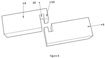
Figure 8 shows a perspective front view of the connection of the sidewalls according to the invention in the longitudinal direction. - The essence of the superstructure according to the invention consists of that the connection of panels with suitable rigidity to each other using suitable joints provides sufficient strength and low weight in the case of an appropriate selection of materials for the manufacture of superstructures suitable for the transportation of goods. Due to the lack of thermal bridges such superstructures may be used to good effect in goods vehicles with a thermally insulated load space.
- In the context of the present invention shipping container is understood to mean transportation apparatuses in which goods may be loaded for the purpose of transportation. These shipping containers are characteristically closed on all sides and are preferably supplied with a loading opening, or door. However, those possibilities are not excluded when these shipping containers are open on at least one side, for example, for the purpose of facilitating unloading. Shipping containers are understood to mean transportation devices secured to goods vehicles with releasable fixing, or transportation devices placed on goods vehicles without securing, which are characteristically rectangular cuboid in shape, but they may also have various shapes depending on the shape of the transported goods and the type of unloading.
- In the context of the present invention superstructure is understood to mean transportation apparatuses that are created together with the chassis of the goods vehicle.
- In the context of the present invention work of art is understood to mean valuable objects the value of which is at least equal to the value of silver of the same weight.
- Both superstructures and shipping containers are secured to the goods vehicle during transportation. The difference between the two transportation apparatuses is that while the shipping container may be lifted off the goods vehicle and the shipping container, along with the goods inside it, may be transferred onto another vehicle or set down onto the ground, a superstructure may not be removed along with the goods from the goods vehicle, instead the goods themselves must be loaded into and out of the superstructure of the goods vehicle. However, from the point of view of the present invention, it is not necessary to differentiate between these two types of transportation apparatus, because the idea behind the invention may be applied to both types of transportation apparatus. Due to this, in the following, in the context of the present invention it will be called a superstructure, but the concept of superstructure will also include shipping containers.
-
Figure 1 shows a superstructure marked in its entirety withreference sign 100. The connection fittings of thesuperstructure 100 each consist of the connection of onenegative profile 1 and one positive profile 2, and these form the frame of the front wall 4, theback wall 5, thesidewalls 6, thefloor element 7 and theroof element 8. The middle parts of each of the individual wall elements are filled with fillingparts 3. Lines separating the individual profiles have been indicated on the front wall 4 for the purpose of better understanding. -
Figure 2 shows thenegative profile 1. Thenegative profile 1 consists of an internal part 1a, anexternal part 1b and agroove 10 located between the two parts, which is for ensuring the structural connection of thesuperstructure 100. -
Figure 3 shows a positive profile 2, thetongue 20 part of which connects into thegroove 10 part of thenegative profile 1. -
Figure 4 shows the layer order of thenegative profile 1. This consists of aninternal core material 11, aresin 15 encompassing this and asubstrate material 13 placed on it. Thesubstrate material 13 is covered withresin 15. Thesubstrate material 13 along with the two layers ofresin 15 form a continuous layer, which in the following is called alaminate 12. In other words thecore material 11 of thenegative profile 1 is covered on all sides by alaminate 12.Armour 14 is glued onto thenegative profile 1 produced in this way onto the front panel a and back panel b parts after formation as a wall element. - The structure of the filling
part 3 containscore material 11. - The walls of the
superstructure 100 may be assembled from thenegative profiles 1, the positive profiles 2, and the fillingparts 3, as is shown infigure 1 . These walls may create a front wall 4, aback wall 5, twosidewalls 6, afloor element 7 and aroof element 8 in the case of a cuboid or rectangularcuboid superstructure 100. - The structure of the
floor element 7 may be seen infigure 5 . Thefloor element 7 consists of fournegative profiles 1 and a fillingpart 3. A frame is created from the fournegative profiles 1, which is made possible by that the ends of thenegative profiles 1 are cut off at an angle of approximately 45° (Figure 1 ). The fillingpart 3 is placed into the middle, empty part of the frame created in this way, in such a way that by itself or with the use ofresin 15 it fills in the space between thenegative profiles 1. - Following this the assembled
floor element 7 is preferably provided with an additional layer oflaminate 12 in the way shown infigure 7 at least on the front panel a and back panel b surfaces so that thefloor element 7 forms a continuous element. The structure may also be reinforced with a layer of balsawood, asadditional substrate material 13, between two layers oflaminate 12 preferably at least on one of its surfaces so that a floor with a greater load-bearing capability is obtained. Furthermore, for the purpose of reinforcing the structure, it may be worthwhile leaving the laminate 12 placed on the back panel b surface longer at the back panel b surface and folding it up at least along the two facing sides so that it covers at least a part of the front panel a surface so as to reinforce the structure of thefloor element 7 in this way. - In the course of the manufacture of the
floor element 7 to facilitate the curing of theresin 15 and, optionally, the adhesive, it is worthwhile placing it on a vacuum table, subjecting it to a pressure of at least 200 mbar and waiting for the final development of the layers, for the curing of the resin to be completed. After the resin has cured,armour 14 is secured to the front panel and back panel of thefloor element 7 on the vacuum table with high-strength structural adhesive. - In the case of assembling the front wall 4 and the
back wall 5, two vertically positionednegative profiles 1 and two horizontally positioned positive profiles 2 are used to create the frame. The fillingpart 3 is placed into the middle, empty part of the front wall 4 andback wall 5 so that by itself or using adhesive orresin 15 it fills the space between thenegative profiles 1 and the positive profiles 2. Following this withlaminate 12 reinforcing,armour 14 is glued to at least the front panel a and back panel b preferably also in a vacuum. - In the case of the assembly of the
roof element 8 fournegative profiles 1 are used to form the frame, and a fillingpart 3 is used in the middle part in such a way that it fills in the empty part of theroof element 8 by itself or with the use of adhesive orresin 15. In order to maintain the rigidity of theroof element 8,armour 14 is secured to its front panel a and to its back panel b using high-strength structural adhesive. - The
sidewalls 6 are produced in the same way as theroof element 8, only with the difference that positive profiles 2 are used instead ofnegative profiles 1. - In order to create the structure of the
superstructure 100, the wall elements produced in the way described above are fitted together in such a way that thetongue parts 20 of the individual wall elements are fitted into thegroove parts 10 of the neighbouring wall elements. - Naturally, the invention is not restricted to the wall elements named above, the order of the layers of the wall elements may be extended on the condition that at least one layer of
laminate 12 orarmour 14 is required on the front panel a and the back panel b in order to keep the wall element together. - The positive profiles 2 of the
sidewalls 6 may be fitted into thenegative profiles 1 of thefloor element 7 with the use of thegrooves 10 and thetongues 20. Following this the front wall 4 and theback wall 5 may be fitted into thenegative profiles 1 of thefloor element 7 and, as the next step, thetongues 20 located on thesidewalls 6 may be fitted into thegrooves 10 of the front wall 4 and theback wall 5.Figure 6 depicts the back right corner of asuperstructure 100 assembled in this way with the assembly of thefloor element 7, theback wall 5 and thesidewall 6. Theroof element 8 may be placed on the structure constructed in this way, thenegative profiles 1 of which slip over thetongues 20 of thesidewalls 6, the front wall 4 and theback wall 5. - This side joint assembly, in other words how a
horizontal groove 10 with avertical tongue 20, or ahorizontal tongue 20 with avertical groove 10 creates the connection between the wall elements, makes it possible to create asuperstructure 100 of the appropriate load-bearing capacity without the use of separate beams or rigidity elements. - Naturally, the individual wall elements may be provided with a door or opening, which opening may be only for permitting the entry of light, closable, or completely open as well, or for permitting the flow of air, for example. In addition, in the case of
superstructures 100 used for various purposes, thesuperstructure 100 may be provided with various accessory apparatuses, such as a cooler, freezer or heating apparatus in the case of heat-sensitive loads, watering apparatus in the case of the transportation of plants, and ventilation apparatus in the case of the transportation of animals, etc. In addition, it is necessary to secure thesuperstructure 100 onto the goods vehicle, or to create it so it is integral with the chassis of the vehicle, which belongs to the compulsory knowledge of the person skilled in the art. - The
superstructure 100 assembled in this way is self-supporting, in other words it maintains its structural state without any external force. For the performance of various logistics tasks, the connection of the individual wall elements to each other may be reinforced with the use of adhesive, own-material adhesive reinforced with asubstrate material 13, withresin 15 used in the production of the profiles, or with the use of other non-releasable fixing methods so that the structure of thesuperstructure 100 is capable of withstanding greater external forces. External forces are understood to mean forces acting upon thesuperstructure 100 from outside, such as objects, vehicles colliding with it, and forces exerted from inside such as forces originating from the movement of the objects or load placed inside thesuperstructure 100. - The roles of the layers used in the case of the individual elements of the
superstructure 100 are different. The role of thecore material 11 is to fill the space so that thesubstrate material 13 has something to secure to. In addition, it has an insulating role, especially if the function of thesuperstructure 100 is the storage of heat-sensitive goods, such as, for example, cooled, frozen goods, or if the objective is to keep the goods warm. Thecore material 11 may be polystyrene foam, PVC foam, polyethylene foam, balsawood, etc. Thecore material 11 may have a honeycomb structure, for example. - The role of the
resins 15 is to secure the various structural layers to each other and to create a smooth surface for the adhesion of thearmour 14. For example, the following may be used as resin 15: epoxy resin, polyester resin, low styrene polyester resin, vinyl ester resin. The selection of theappropriate resin 15 belongs to the compulsory knowledge of the person skilled in the art in the knowledge of thecore material 11 and thesubstrate material 13. - The role of the
substrate material 13 is to reinforce the load-bearing capacity and durability of the individual wall elements. Thesubstrate material 13 makes it possible for the individual wall elements to withstand the weight of larger consignments and to be resistant to external forces.Such substrate material 13 may be glass fibre matting, woven glass fibre, biaxial fibreglass, balsawood, or carbon fibre, aramid. - The role of the
armour 14 used as the protective covering is to keep the wall elements together and to provide external protection.Possible armour 14 materials include plastic, preferably glass fibre reinforced polyester panelling, polyester panelling, or metal panelling, such as aluminium or steel. - The
armour 14 used for keeping the completed wall elements together and as an external covering is secured to the given wall element using adhesive. Such adhesive may be MS polymer, polyurethane, hybrid or two-component structural adhesive, or theresin 15 used for the wall elements with thesubstrate material 13 or without it. - The assembly of the superstructures may take place in four steps, when in the first step the
negative profiles 1 and the positive profiles 2 are manufactured, which perform a bracing role, and it is through these that the various wall elements are connected to each other. The length of the profiles is formed so that they correspond to the length of the planned wall element, preferably a certain length shorter than the wall element itself in order to make it possible to glue the elements. Furthermore, due to the 90° connection between the walls that is generally used, it is necessary to form the ends of the profiles at an angle of 45°. Naturally, if certain of the walls of thesuperstructure 100 connecting to one another are not at right angles to each other, the ends of the profiles must be formed at a different angle, as is known to the person skilled in the art. - In the second step the individual wall elements are created in such a way that the frame of the given wall element is assembled using the
negative profiles 1 and/or the positive profiles 2, and the empty area enclosed by the profiles is filled with core material, thereby creating the fillingpart 3 element. Depending on use,additional laminate 12,substrate 13 may be secured to a part of or to the entire assembled wall element. For example, in the case of afloor element 7 at least one of the entire surfaces of thefloor element 7, preferably surface a may be preferably covered with balsawood and/or biaxial fibreglass assubstrate material 13, so that it can withstand the load of the cargo. -
Figure 7 shows the order of the layers of an embodiment of thefloor element 7, which progressing from the inside to the outside containscore material 11. Thecore material 11 is covered on both sides by alaminate 12. Due to the load-bearing capacity of thefloor element 7, a balsawood layer is also used assubstrate material 13 on the future upper surface, which is again covered withlaminate 13 so that thearmour 14 may be secured onto it as external covering. Furthermore, in order to reinforce the structure, the laminate 12 on the surface opposite to the surface reinforced withsubstrate material 13 is left longer and folded up onto the surface covered withsubstrate material 13, which in this way covers it from above at the edges. Due to this thearmour 14, as shown infigure 5 , is thinner on surfaces above the laminate 12, and where there is no laminate 12, there it is thicker for the purpose of ensuring an even surface. Naturally those solutions are not excluded when the laminate 12 is thicker at the inner parts, or due to the pressure exerted the layers at the external parts are more compacted, thereby creating tight contact on the entire surface. - In the third step the
armour 14, preferably fibreglass reinforced polyester panelling, is secured to the surface of the front panel a and of the back panel b of the wall element. - In the last step the assembled wall elements are fitted to one another, thereby creating the
superstructure 100. - In the case of manufacture performed in two steps there is no need for the separate manufacture of profiles and filling parts, instead by using a tool corresponding to the size of the wall element, the wall elements are produced in one step using the
aforementioned groove 10 andtongue 20 formations. At least one layer oflaminate 12, optionally withfurther substrate material 13 reinforcing, is placed onto the front panel a and onto the back panel b of the wall element containingcore material 11. Additionally, in thesecond step armour 14 is applied onto the wall element, onto its front panel a and back panel b. - In the case of single-step manufacture, the wall elements are produced in one step and at least two layers of the laminate 12 are applied. Preferably they are treated with a gel or other surface-protection agent, as in the case of single-step manufacture the laminate 12 takes on the role of the
armour 14 and the gel or other surface-protection agent is important from the point of view of UV protection. - In the cases of wall elements with large dimensions, it may be necessary to assemble these from several elements. In such cases, in the way according to
figure 8 , both thegroove 10 and thetongue 20 parts are formed on the same wall element, which connect to asidewall element 6 formed in the same way. Such a joint also serves as additional bracing in the longitudinal or lateral direction, when this is required due to greater loading. - In the first step the
negative profiles 1 and the positive profiles 2 used for the purpose of bracing and as connection elements are manufactured, preferably using a tool-pair (tools for producing grooves and tongues). The width of the profiles is 75 mm and the height of the profiles is 20 mm. The height of the profiles determines the thickness of the wall element assembled from them. Thegroove 10 has dimensions of 18*18 mm, and the dimensions of the tongue are 14*14 mm. Thecore material 11 used in the case of the profiles is polystyrene foam, and SR 8500 epoxy resin andlaminate 12 containing biaxial fibreglass are secured onto its entire surface. - In the second step the individual wall elements are created. In the case of the
floor element 7, the frame is formed with fournegative profiles 1 and the fillingpart 3 is filled withcore material 11 consisting of XPS polystyrene foam. Following this the laminate 12 is placed on the entire front panel a and back panel b of thefloor element 7. - The wall element is placed on a vacuum table under a pressure of 200 mbar to facilitate the curing of the
resin 15 used in thelaminate 12. - Four
negative profiles 1 are also used in the case of theroof element 8 and the fillingpart 3 is filled with XPS polystyrene foam. Theroof element 8 does not containadditional substrate material 13 orlaminate 12. - The front wall 4 and the
back wall 5 contain two verticalnegative profiles 1 and two horizontal positive profiles 2 in addition to thecore material 11 of XPS polystyrene foam serving as the fillingpart 3. - The
sidewalls 6 contain four positive profiles 2, apart from this their production corresponds to that described in the case of theroof element 8. - In the
third step armour 14 consisting of polyester panelling is secured to both surfaces of the wall elements on a vacuum table using two-component structural adhesive. - Finally, in the fourth step, the individual wall elements are assembled and the gaps are filled with SR 8500 epoxy resin, thereby creating the
superstructure 100. - The structure of the
superstructure 100 according to example 1 may be reinforced with the use of larger-sized elements. The height of thenegative profile 1 according to the example is 90 mm and its width is 320 mm. The size of thegroove 10 is 40*40 mm. The height of the positive profile 2 is 90 mm and its width is 320 mm. The size of thetongue 20 is 37*37 mm. - Furthermore, the
floor element 7 is covered with a layer of balsawood, asadditional substrate material 13, on its front panel a , onto which a further layer oflaminate 12 is placed and the laminate 12 placed on the back panel b is folded up onto this last layer ofupper laminate 12. At the same time the other wall elements are also reinforced withlaminate 12 covering their entire front panels a . A pressure of 460 mbar is applied on the vacuum table. - In the case of the use of the
superstructure 100 for the transportation of heat-sensitive goods, XPS polystyrene is used ascore material 11 due to its insulation ability and low weight, because, due to this, it may be used at a greater thickness. - The
superstructure 100 may be used for the transportation of valuable goods, especially money, gold or works of art. In this case metaaramid substrate material 13 and epoxy resin subjected to a ballistics test are used in thelaminate 12. - The advantage of the solution according to the invention is that there is no need for separate beams or braces for the connection of the individual wall elements, which makes manufacture simpler and cheaper. In addition, due to the materials used, the side joints and the lack of separate beams, the weight of the
superstructure 100 may be reduced as compared to the state of the art. A significant advantage of thesuperstructure 100 according to the invention is that due to the lack of beams thermal bridges reducing the effectiveness of the insulation are not formed. - A further advantage of the solution according to the invention is that
superstructures 100 that may be used for various purposes may be produced by varying the core material and the laminate.
Claims (11)
- Superstructure (100) especially for goods vehicles with a thermally insulated load space, which has wall elements (4, 5, 6, 7, 8) and armour (14), characterised in that the wall elements (4, 5, 6, 7, 8) are constructed from negative profiles (1) and/or positive profiles (2) and a filling part (3), the negative profiles (1) and/or the positive profiles (2) form a frame that encompasses a filling part (3), the wall elements (4, 5, 6, 7, 8) have a front panel ( a ) and a back panel ( b ), and tongues (20) located on the positive profiles (2) of the individual wall elements connect into grooves (10) located on the negative profiles (1) of the neighbouring wall elements.
- Superstructure (100) according to claim 1, characterised in that the order of the layers of the negative profiles (1) and the positive profiles (2) forming the wall elements from the inside progressing towards the outer sides is as follows: core material (11) and laminate (12); which laminate (12) contains resin (15) and a substrate material (13); and the filling part (3) of the wall elements contains core material (11).
- Superstructure (100) according to claim 1 or 2, characterised in that the core material (11) is selected from among the following: polystyrene foam, PVC foam, polyethylene foam, balsawood, or a combination of these; the substrate material (13) is selected from among the following: glass fibre matting, woven glass fibre, biaxial fibreglass, balsawood, or carbon fibre, aramid, or a combination of these; and the resin (15) is selected from among the following: epoxy resin, polyester resin, low styrene polyester resin, vinyl ester resin, or a combination of these.
- Superstructure (100) according to any of claims 1 to 3, characterised in that the armour (14) is polyester panelling, or metal panelling, preferably glass fibre reinforced polyester panelling.
- Superstructure (100) according to any of claims 2 to 4, characterised in that the core material (11) is polystyrene foam, the substrate material (13) is biaxial fibreglass, and the resin (15) is epoxy resin.
- Superstructure (100) according to any of claims 2 to 5, characterised in that among the wall elements one of them is a floor element (7), and at least one front panel ( a ) and/or back panel (b) of the floor element (7) contains at least one further layer of laminate (12), and preferably at least one further layer of balsawood as substrate material (13) between two layers of laminate (12).
- Superstructure (100) according to any of claims 1 to 6, characterised in that the front panel ( a ) and the back panel ( b ) of the wall elements are provided with armour (14) in such a way that after the wall elements have been secured to each other substantially the entire surface of the front panel ( a ) and the back panel ( b ) are covered with armour (14).
- Superstructure (100) according to any of claims 1 to 7, characterised in that the superstructure (100) contains an apparatus selected form the following: cooling apparatus, freezing apparatus, heating apparatus, ventilation apparatus, watering apparatus and a combination of these.
- Method for the manufacture of the superstructure (100) according to any of claims 1 to 8, which contains the following steps:a) Forming a frame from negative profiles (1) and/or positive profiles (2) and the space delimited in this way is filled with core material (11) in order to create the filling part (3);b) Covering the finished wall elements with armour (14), preferably with glass fibre reinforced polyester panelling to the extent that after the wall panels have been secured to each other the entire free surface of the front panel ( a ) and the back panel ( b ) is covered;c) Fitting together the finished wall elements using the grooves (10) located in the negative profiles (1) and the tongues (20) located in the positive profiles (2), preferably the space remaining at the joints is filled with adhesive or resin (15).
- The use of the superstructure (100) according to any of claims 1 to 8 for the transportation of heat-sensitive goods.
- The use of the superstructure (100) according to any of claims 1 to 8 for the transportation of works of art, money, gold.
Applications Claiming Priority (2)
| Application Number | Priority Date | Filing Date | Title |
|---|---|---|---|
| HU2000314A HUP2000314A1 (en) | 2020-09-25 | 2020-09-25 | Thermally insulated truck body and method of making such truck body |
| PCT/HU2021/050052 WO2022064232A1 (en) | 2020-09-25 | 2021-09-22 | Superstructure, especially for goods vehicles with thermally insulated load space, and method for the manufacture of such superstructure |
Publications (3)
| Publication Number | Publication Date |
|---|---|
| EP4217255A1 EP4217255A1 (en) | 2023-08-02 |
| EP4217255B1 true EP4217255B1 (en) | 2025-01-29 |
| EP4217255C0 EP4217255C0 (en) | 2025-01-29 |
Family
ID=89993196
Family Applications (1)
| Application Number | Title | Priority Date | Filing Date |
|---|---|---|---|
| EP21831098.5A Active EP4217255B1 (en) | 2020-09-25 | 2021-09-22 | Superstructure, especially for goods vehicles with thermally insulated load space, and method for the manufacture of such superstructure |
Country Status (3)
| Country | Link |
|---|---|
| EP (1) | EP4217255B1 (en) |
| HU (2) | HUP2000314A1 (en) |
| WO (1) | WO2022064232A1 (en) |
Family Cites Families (3)
| Publication number | Priority date | Publication date | Assignee | Title |
|---|---|---|---|---|
| SG115594A1 (en) * | 2003-11-26 | 2005-10-28 | Fagerdala Singapore Pte Ltd | Insulated panels and shipping container incorporating said panels |
| JP2012144054A (en) * | 2011-01-06 | 2012-08-02 | Sugawa Shatai Kk | Cargo box and method of manufacturing the same |
| EP2524856B1 (en) * | 2011-05-20 | 2014-07-02 | Schmitz Cargobull AG | Superstructure for a commercial vehicle |
-
2020
- 2020-09-25 HU HU2000314A patent/HUP2000314A1/en unknown
-
2021
- 2021-09-22 EP EP21831098.5A patent/EP4217255B1/en active Active
- 2021-09-22 HU HUE21831098A patent/HUE070322T2/en unknown
- 2021-09-22 WO PCT/HU2021/050052 patent/WO2022064232A1/en not_active Ceased
Also Published As
| Publication number | Publication date |
|---|---|
| HUE070322T2 (en) | 2025-05-28 |
| HUP2000314A1 (en) | 2022-03-28 |
| EP4217255A1 (en) | 2023-08-02 |
| EP4217255C0 (en) | 2025-01-29 |
| WO2022064232A1 (en) | 2022-03-31 |
Similar Documents
| Publication | Publication Date | Title |
|---|---|---|
| US7334697B2 (en) | ISO container | |
| US9718608B2 (en) | Transport container | |
| US10633877B2 (en) | System and method of manufacturing transportable buildings | |
| US5507405A (en) | Thermally insulated cargo container | |
| US20090242552A1 (en) | Iso container having a load transfer plate | |
| US8484929B1 (en) | Construction of modular underground storage facilities | |
| US9828164B2 (en) | Intermodal container and method of constructing same | |
| EP0520745B1 (en) | Air cargo containers | |
| EP0505927B1 (en) | Missile canister and method of fabrication | |
| HK1002606B (en) | Air cargo containers | |
| CN101720300A (en) | shipping container | |
| CN103764520A (en) | Movable storage warehouse | |
| US10822163B2 (en) | Lightweight metallic shipping container | |
| EP1495200A1 (en) | Barrier-protected container | |
| GB2476110A (en) | Transport pallet with insulating means | |
| EP4217255B1 (en) | Superstructure, especially for goods vehicles with thermally insulated load space, and method for the manufacture of such superstructure | |
| US3501875A (en) | Construction of buildings | |
| CN110182480B (en) | Module assembled container and transport unit | |
| CN209635077U (en) | Modular assembly type container and bottom module, top module, side module, delivery unit | |
| EP2428463B1 (en) | Refrigerated container | |
| US11390456B2 (en) | Assemblies, systems and methods for maturation of distilled spirits | |
| US12486103B2 (en) | Carbon fiber air cargo container | |
| CN112239030A (en) | Light-weight metal transport container with metal porous floor with multiple cell wall thicknesses | |
| CA2987897A1 (en) | Lightweight metallic shipping container | |
| DE102010032309A1 (en) | Container for e.g. transporting fruits in ship, has components made of fiber-reinforced plastics and fiber-reinforced plastics composite material, where values of load data are applicable to ISO standard |
Legal Events
| Date | Code | Title | Description |
|---|---|---|---|
| STAA | Information on the status of an ep patent application or granted ep patent |
Free format text: STATUS: UNKNOWN |
|
| STAA | Information on the status of an ep patent application or granted ep patent |
Free format text: STATUS: THE INTERNATIONAL PUBLICATION HAS BEEN MADE |
|
| PUAI | Public reference made under article 153(3) epc to a published international application that has entered the european phase |
Free format text: ORIGINAL CODE: 0009012 |
|
| STAA | Information on the status of an ep patent application or granted ep patent |
Free format text: STATUS: REQUEST FOR EXAMINATION WAS MADE |
|
| 17P | Request for examination filed |
Effective date: 20230329 |
|
| AK | Designated contracting states |
Kind code of ref document: A1 Designated state(s): AL AT BE BG CH CY CZ DE DK EE ES FI FR GB GR HR HU IE IS IT LI LT LU LV MC MK MT NL NO PL PT RO RS SE SI SK SM TR |
|
| DAV | Request for validation of the european patent (deleted) | ||
| DAX | Request for extension of the european patent (deleted) | ||
| GRAP | Despatch of communication of intention to grant a patent |
Free format text: ORIGINAL CODE: EPIDOSNIGR1 |
|
| STAA | Information on the status of an ep patent application or granted ep patent |
Free format text: STATUS: GRANT OF PATENT IS INTENDED |
|
| RIC1 | Information provided on ipc code assigned before grant |
Ipc: B65D 90/08 20060101ALI20240802BHEP Ipc: B65D 90/02 20190101ALI20240802BHEP Ipc: B62D 33/04 20060101AFI20240802BHEP |
|
| INTG | Intention to grant announced |
Effective date: 20240816 |
|
| GRAS | Grant fee paid |
Free format text: ORIGINAL CODE: EPIDOSNIGR3 |
|
| GRAA | (expected) grant |
Free format text: ORIGINAL CODE: 0009210 |
|
| STAA | Information on the status of an ep patent application or granted ep patent |
Free format text: STATUS: THE PATENT HAS BEEN GRANTED |
|
| AK | Designated contracting states |
Kind code of ref document: B1 Designated state(s): AL AT BE BG CH CY CZ DE DK EE ES FI FR GB GR HR HU IE IS IT LI LT LU LV MC MK MT NL NO PL PT RO RS SE SI SK SM TR |
|
| REG | Reference to a national code |
Ref country code: GB Ref legal event code: FG4D |
|
| REG | Reference to a national code |
Ref country code: CH Ref legal event code: EP |
|
| REG | Reference to a national code |
Ref country code: DE Ref legal event code: R096 Ref document number: 602021025584 Country of ref document: DE |
|
| REG | Reference to a national code |
Ref country code: IE Ref legal event code: FG4D |
|
| U01 | Request for unitary effect filed |
Effective date: 20250217 |
|
| U07 | Unitary effect registered |
Designated state(s): AT BE BG DE DK EE FI FR IT LT LU LV MT NL PT RO SE SI Effective date: 20250224 |
|
| REG | Reference to a national code |
Ref country code: HU Ref legal event code: AG4A Ref document number: E070322 Country of ref document: HU |
|
| PG25 | Lapsed in a contracting state [announced via postgrant information from national office to epo] |
Ref country code: RS Free format text: LAPSE BECAUSE OF FAILURE TO SUBMIT A TRANSLATION OF THE DESCRIPTION OR TO PAY THE FEE WITHIN THE PRESCRIBED TIME-LIMIT Effective date: 20250429 |
|
| PG25 | Lapsed in a contracting state [announced via postgrant information from national office to epo] |
Ref country code: PL Free format text: LAPSE BECAUSE OF FAILURE TO SUBMIT A TRANSLATION OF THE DESCRIPTION OR TO PAY THE FEE WITHIN THE PRESCRIBED TIME-LIMIT Effective date: 20250129 |
|
| PG25 | Lapsed in a contracting state [announced via postgrant information from national office to epo] |
Ref country code: ES Free format text: LAPSE BECAUSE OF FAILURE TO SUBMIT A TRANSLATION OF THE DESCRIPTION OR TO PAY THE FEE WITHIN THE PRESCRIBED TIME-LIMIT Effective date: 20250129 |
|
| PG25 | Lapsed in a contracting state [announced via postgrant information from national office to epo] |
Ref country code: IS Free format text: LAPSE BECAUSE OF FAILURE TO SUBMIT A TRANSLATION OF THE DESCRIPTION OR TO PAY THE FEE WITHIN THE PRESCRIBED TIME-LIMIT Effective date: 20250529 Ref country code: NO Free format text: LAPSE BECAUSE OF FAILURE TO SUBMIT A TRANSLATION OF THE DESCRIPTION OR TO PAY THE FEE WITHIN THE PRESCRIBED TIME-LIMIT Effective date: 20250429 |
|
| PG25 | Lapsed in a contracting state [announced via postgrant information from national office to epo] |
Ref country code: HR Free format text: LAPSE BECAUSE OF FAILURE TO SUBMIT A TRANSLATION OF THE DESCRIPTION OR TO PAY THE FEE WITHIN THE PRESCRIBED TIME-LIMIT Effective date: 20250129 |
|
| PG25 | Lapsed in a contracting state [announced via postgrant information from national office to epo] |
Ref country code: GR Free format text: LAPSE BECAUSE OF FAILURE TO SUBMIT A TRANSLATION OF THE DESCRIPTION OR TO PAY THE FEE WITHIN THE PRESCRIBED TIME-LIMIT Effective date: 20250430 |
|
| PG25 | Lapsed in a contracting state [announced via postgrant information from national office to epo] |
Ref country code: SM Free format text: LAPSE BECAUSE OF FAILURE TO SUBMIT A TRANSLATION OF THE DESCRIPTION OR TO PAY THE FEE WITHIN THE PRESCRIBED TIME-LIMIT Effective date: 20250129 |
|
| U20 | Renewal fee for the european patent with unitary effect paid |
Year of fee payment: 5 Effective date: 20250901 |
|
| PGFP | Annual fee paid to national office [announced via postgrant information from national office to epo] |
Ref country code: HU Payment date: 20250915 Year of fee payment: 5 |
|
| PG25 | Lapsed in a contracting state [announced via postgrant information from national office to epo] |
Ref country code: CZ Free format text: LAPSE BECAUSE OF FAILURE TO SUBMIT A TRANSLATION OF THE DESCRIPTION OR TO PAY THE FEE WITHIN THE PRESCRIBED TIME-LIMIT Effective date: 20250129 |
|
| PG25 | Lapsed in a contracting state [announced via postgrant information from national office to epo] |
Ref country code: SK Free format text: LAPSE BECAUSE OF FAILURE TO SUBMIT A TRANSLATION OF THE DESCRIPTION OR TO PAY THE FEE WITHIN THE PRESCRIBED TIME-LIMIT Effective date: 20250129 |
|
| PLBE | No opposition filed within time limit |
Free format text: ORIGINAL CODE: 0009261 |
|
| STAA | Information on the status of an ep patent application or granted ep patent |
Free format text: STATUS: NO OPPOSITION FILED WITHIN TIME LIMIT |
|
| 26N | No opposition filed |
Effective date: 20251030 |
|
| REG | Reference to a national code |
Ref country code: HU Ref legal event code: HC9C Owner name: CHRIS COLUMBUS KFT., HU |