EP4217238B1 - Vehicle display system with height adjustment - Google Patents
Vehicle display system with height adjustment Download PDFInfo
- Publication number
- EP4217238B1 EP4217238B1 EP21811030.2A EP21811030A EP4217238B1 EP 4217238 B1 EP4217238 B1 EP 4217238B1 EP 21811030 A EP21811030 A EP 21811030A EP 4217238 B1 EP4217238 B1 EP 4217238B1
- Authority
- EP
- European Patent Office
- Prior art keywords
- bracket
- display
- adjustment
- display system
- cover
- Prior art date
- Legal status (The legal status is an assumption and is not a legal conclusion. Google has not performed a legal analysis and makes no representation as to the accuracy of the status listed.)
- Active
Links
Images






Classifications
-
- B—PERFORMING OPERATIONS; TRANSPORTING
- B60—VEHICLES IN GENERAL
- B60R—VEHICLES, VEHICLE FITTINGS, OR VEHICLE PARTS, NOT OTHERWISE PROVIDED FOR
- B60R11/00—Arrangements for holding or mounting articles, not otherwise provided for
- B60R11/02—Arrangements for holding or mounting articles, not otherwise provided for for radio sets, television sets, telephones, or the like; Arrangement of controls thereof
- B60R11/0229—Arrangements for holding or mounting articles, not otherwise provided for for radio sets, television sets, telephones, or the like; Arrangement of controls thereof for displays, e.g. cathodic tubes
- B60R11/0235—Arrangements for holding or mounting articles, not otherwise provided for for radio sets, television sets, telephones, or the like; Arrangement of controls thereof for displays, e.g. cathodic tubes of flat type, e.g. LCD
-
- B—PERFORMING OPERATIONS; TRANSPORTING
- B60—VEHICLES IN GENERAL
- B60R—VEHICLES, VEHICLE FITTINGS, OR VEHICLE PARTS, NOT OTHERWISE PROVIDED FOR
- B60R11/00—Arrangements for holding or mounting articles, not otherwise provided for
- B60R2011/0001—Arrangements for holding or mounting articles, not otherwise provided for characterised by position
- B60R2011/0003—Arrangements for holding or mounting articles, not otherwise provided for characterised by position inside the vehicle
- B60R2011/0019—Side or rear panels
- B60R2011/0022—Pillars
-
- B—PERFORMING OPERATIONS; TRANSPORTING
- B60—VEHICLES IN GENERAL
- B60R—VEHICLES, VEHICLE FITTINGS, OR VEHICLE PARTS, NOT OTHERWISE PROVIDED FOR
- B60R11/00—Arrangements for holding or mounting articles, not otherwise provided for
- B60R2011/0042—Arrangements for holding or mounting articles, not otherwise provided for characterised by mounting means
- B60R2011/008—Adjustable or movable supports
-
- B—PERFORMING OPERATIONS; TRANSPORTING
- B60—VEHICLES IN GENERAL
- B60R—VEHICLES, VEHICLE FITTINGS, OR VEHICLE PARTS, NOT OTHERWISE PROVIDED FOR
- B60R2300/00—Details of viewing arrangements using cameras and displays, specially adapted for use in a vehicle
- B60R2300/20—Details of viewing arrangements using cameras and displays, specially adapted for use in a vehicle characterised by the type of display used
- B60R2300/202—Details of viewing arrangements using cameras and displays, specially adapted for use in a vehicle characterised by the type of display used displaying a blind spot scene on the vehicle part responsible for the blind spot
Definitions
- the present disclosure relates to a vehicle display system.
- Vehicles are increasingly moving toward implementation of cameras and electronic display systems to provide additional safety and security systems.
- the placement of such a display system needs to be visible to the driver in order to access the information provided and be retained in the event of an impact scenario.
- Current display systems are not efficient at retaining the respective position of the display system and do not account for differences in driver eye height. Additionally, current display systems require specific tooling to facilitate the adjustment of the display system. This results in the user requiring additional time and difficulty to adjust the display system.
- US 2019/263327 A1 describes a monitor of a camera-monitor system in a motor vehicle, the monitor comprising: a display mounted in a field of vision of a driver of the motor vehicle; wherein a vertical position of the monitor is adjustable and does not affect a horizontal position of the monitor; and wherein the vertical position of the monitor is held by both a force fit and a form fit; a spring exerting a force establishing the force fit; a sliding element; a holding element including a slide rail for the sliding element; wherein the sliding element includes a toothing on a first longitudinal side and, on its second longitudinal side lying opposite the first longitudinal side, strikes against a rail; wherein the rail is supported in relation to the holding element by means of springs; the holding element includes a rack lying opposite the toothing of the sliding element; and the slide rail is connected in a horizontally displaceable manner to the holding element.
- a vehicle display system which comprises: a bracket; at least one bracket support member wherein the bracket support member comprises a receiving cavity to retain the bracket; a display cover coupled to the at least one bracket support member; a display adapter coupled to the display cover; and at least one adjustment mechanism coupled to the display cover, wherein the adjustment mechanism comprises at least one mounting member that couples to the display adapter, wherein the mounting member comprises at least one first bracket element and at least one second bracket element; a lever that is slidably engaged within the first bracket element; and a biasing element supported by the second bracket element; wherein the biasing member cooperates with the lever such that, when a first force is applied to the lever the biasing member is compressed to enable the adjustment mechanism to be translated to a desired position.
- the bracket may be mounted to an attachment component for facilitating coupling to a vehicle directly or indirectly.
- This attachment component may be configured for driver side and/or passenger side mounting.
- An example attachment component is describe in US 63/065,627 with the title "Vehicle Display Retention Assembly” filed on August 14, 2020 , and reference is made thereto with respect to attachment details.
- the vehicle display system further comprises at least one fastening member for coupling the display adapter to the display cover such that, when the fastening member is loosened, the adjustment mechanism is functional to enable movement of the display cover in relation to the bracket, and, when the fastening member is tightened, the movement of the adjustment mechanism is restricted.
- each fastening member comprises a locking lever, with the locking lever preferably being rotatable between an open position loosening the fastening member and a closed position tightening the fastening member, and/or each fastening member comprising an eccentric screw.
- Preferred embodiments of the vehicle display system according to the invention further comprise at least one first gasket located between the bracket support member and the display cover, and/or at least second first gasket located between the display cover and the display adapter, with preferably each second gasket being designed to fit on one fastening member.
- At least one tolerance biasing element is located between the display cover and the first gasket, preferably arranged on either the inside or outside of the bracket support member.
- the tolerance biasing element cooperates with a side wall of the bracket support member and the display cover to ensure alignment of the bracket support member, and/or the tolerance biasing element cooperates with the display adapter and the bracket support member to ensure a proper mounted alignment.
- the adjustment mechanism further comprises an adjustment pin that cooperates with the biasing element; and an adjustment rod that cooperates with the adjustment pin, with the adjustment rod preferably being integrally connected to the bracket or detachably coupled to the bracket.
- embodiments of the present invention can be further characterized by a dividing wall, wherein the cover has the dividing wall as a physical barrier separating two adjustment mechanisms, and/or the biasing members of two adjustment mechanisms cooperate with the respective levers and the dividing wall such that, when a first force is applied to the levers the biasing members are compressed against the dividing wall to enable the adjustment mechanisms and a display screen to be translated to a desired height position, and/or, per adjustment mechanism, the lever engages and compresses the biasing member against the dividing wall for translating the adjustment pin out of the corresponding geometry of the adjustment rod.
- each fastening member preferably cooperating with one adjustment mechanism retaining the location of the display cover in relation to the bracket, when the fastening member is in a locked position.
- bracket support members between which the bracket can be vertically moved for a height adjustment, with preferably the bracket support members providing a dovetail guiding.
- bracket support members located in proximity to the four corners of the bracket, and/or there are two first gaskets located between each bracket support member and the display cover, with preferably the first gaskets being injected into the display system during assembly.
- Embodiments of the invention can further comprise at least one display screen coupled with the display adapter; wherein preferably a bezel encases the display screen.
- the display screen comprises bonded glass.
- the display adapter and/or the bracket is constructed from aluminum or a high-tech plastic material.
- An electromagnetic shield adapter unit for cooling electric components of the vehicle display system in particular its electronic control unit, may also be used, for example in form of the unit describe in US 63/065,606 with the title “Electromagnetic Shielding (EMC) Adapter within Vehicle Display Unit” filed on August 14, 2020 , and reference is made thereto with respect to the respective structural details.
- EMC Electromagnetic Shielding
- FIG. 1a depicts an isometric perspective view of a display system 10 for a vehicle 1.
- the display system 10 comprises a display screen 11 and a bezel 12.
- the bezel 12 surrounds the display screen 11, wherein the display screen 11 is a form of bonded glass. Further, the bezel 12 may be configured to accept paint to alter the appearance of the bezel 12.
- the display system 10 further comprises an inner bracket cover 13 and an outer bracket cover 14.
- the outer bracket cover 14 and inner bracket cover 13 cooperate to provide protection and improved appearance for a bracket 16, shown in FIG. 2 .
- the bracket 16 provides a means for attachment of the display system 10 to a vehicle 1.
- the bracket 16 may be mounted to an attachment component for facilitating coupling to the vehicle directly or indirectly. This attachment component may be configured for driver side and/or passenger side mounting.
- FIG. 1b An example attachment component is describe in US 63/065,627 with the title "Vehicle Display Retention Assembly” filed on August 14, 2020 , and reference is made thereto with respect to attachment details.
- the display system 10 mounts to a vehicle A-pillar.
- the display system may mount to a vehicle door, a windshield, a grab bar attached to the vehicle, or any other vehicle structure.
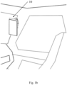
- FIG. 1b depicts the display system 10 mounted to the A-pillar of the vehicle 1, with the display system 10 being adjustable up to 75mm while maintaining crash safety requirements.
- the adjustability of this design enables movement of the perpendicular of the display system 10 to align with the eyes of the driver (not shown).
- This design also allows for the adjustment of the display system 10 without additional tooling such as screw drivers, hammers, hex keys, or similar devices.
- FIG. 2 depicts an exploded view of the display system 10 emphasizing a vehicle display height adjustment assembly.
- the inner bracket cover 13 and the outer bracket cover 14 cooperate with the bracket 16.
- the bracket 16 facilitates the connection between the display system 10 and the vehicle 1 by attaching to the A-pillar.
- the bracket 16 is coupled to a display cover 30 via at least two bracket support members 22. In this configuration, there are four bracket support members 22 located in proximity to the four corners of the bracket 16.
- the bracket 16 is designed to be slidably coupled within the bracket support members 22.
- the bracket support members 22 are coupled to the display cover 30 and a display adapter 34 via at least one bracket support fastener 24. In this configuration, two bracket support fasteners 24 are used for each bracket support member 22 and are located in opposite corners of the bracket support member 22.
- the display adapter 34 and the bracket 16 are constructed from aluminum or a high-tech plastic material. These material ensure forces applied to the display system are strucutrally received and contained by the display adaptor 34 or the bracket 16.
- An electromagnetic shield adapter unit for cooling electric components of the vehicle display system in particular its electronic control unit, may be used, for example in form of the unit describe in US 63/065,606 with the title "Electromagnetic Shielding (EMC) Adapter within Vehicle Display Unit” filed on August 14, 2020 , hereby incorporated by reference, and reference is made thereto with respect to the respective structural details.
- EMC Electromagnetic Shielding
- At least one first gasket 26 is located between the bracket support member 22 and the display cover 30.
- Each first gasket 26 reduces system vibration, and may seal the system to inhibit the transfer of contaminants.
- two first gaskets 26 are located between each bracket support member 22 and the display cover 30.
- the first gaskets 26 are injected into the display system 10 during assembly.
- the first gaskets 26 may be incorporated into the display system 10 via other means during assembly as well.
- each tolerance biasing element 28 Located between the display cover 30 and the first gaskets 26 is at least one tolerance biasing element 28. In this configuration there is one tolerance biasing element 28 with each bracket support member 22. In other configurations there may be more than one tolerance biasing element 28. Each tolerance biasing element 28 may be located on either the inside or outside of the bracket support member 22.
- the tolerance biasing elements 28 cooperate with a side wall 45, see FIG. 5 , of the bracket support member 22 and the display cover 30 to ensure alignment of the bracket support member 22. In other configurations the tolerance biasing element 28 may cooperate with the display adapter 34 and the bracket support member 22 to ensure a proper mounted alignment.
- an adjustment mechanism 20 is coupled to the display cover 30 and display adapter 34 via at least one adjustment mechanism fastener 18 and positioned between the display cover 30 and the bracket 16.
- the height of the display system 10 may be adjusted by the cooperation of the adjustment mechanism 20 with the display cover 30 and the bracket 16. In this configuration there are two adjustment mechanisms 20. However, other designs may have more or less adjustment mechanisms 20 to meet design requirements.
- the display adapter 34 is coupled to the display cover 30. At least one fastening member 36 cooperates with the display adapter 34 and the display cover 30. When the fastening member 36 is loosened, the adjustment mechanism 20 is functional to enable movement of the display cover 30 in relation to the bracket 16. Whereas, when the fastening member 36 is tightened, the movement of the adjustment mechanism 20 is restricted. In this configuration there are two fastening members 36, which are eccentric screws. Alternatively, there can be more or less of these in other configurations to comply with design requirements.
- each second gasket 32 is able to reduce vibration, and seal the system to inhibit the transfer of contaminants. In this configuration there are two second gaskets 32, but in other configurations there may be more or less to meet design requirements.
- FIG. 3 depicts a front view of the vehicle display height adjustment assembly.
- the bracket 16 is designed to be positioned between the bracket support members 22 and be slidably coupled.
- the tolerance biasing elements 28 are located on the outside of the two bracket support members 22 on the left side and on the inside of the two bracket support members 22 on the right side.
- the tolerance biasing elements 28 may be located on the inside or outside of all bracket support members 22.
- the tolerance biasing elements 28 shift the bracket support members 22 onto a support area in the display adapter 34.
- the support areas are in parallel within a specific range to decrease the tolerance range of the bracket support members 22 to each other. This prevents the system from jamming, and ensures it is robust and of high quality.
- the vehicle display height adjustment assembly contains two adjustment mechanisms 20. Both adjustment mechanisms 20 are engaged simultaneously in order to adjust the display system 10. This ensures that a user will need to use both hands to engage both adjustment mechanisms 20 and provide the required support to inhibit the display system 10 slipping into an unintended end position.
- Each adjustment mechanism 20 is comprised of a lever 38, a first bracket element 40, a second bracket element 42, and a biasing member 44.
- the first bracket element 40 and the second bracket element 42 are coupled to the display adapter 34 via four adjustment mechanism fasteners 18 for each bracket.
- the first bracket element 40 supports the lever 38 and acts as a guide for when the lever 38 is slidably engaged.
- the second bracket element 42 supports the biasing member 44. In this configuration the second bracket element 42 acts as a guide for the biasing member 44. In other configurations the biasing member 44 and/or second bracket element 42 may be coupled to a dividing wall 46 shown in FIG. 4 .
- the fastening member 36 is located near the adjustment mechanism 20 and cooperates with the adjustment mechanism 20 to assist in retaining the location of the display cover 30 in relation to the bracket 16. When the fastening member 36 is in a locked position, the fastening member 36 provides sufficient force to retain display adapter 34 to the bracket 16.
- FIG. 4 a top perspective view of the vehicle display height adjustment assembly is shown.
- the inner bracket cover 13 and the outer bracket cover 14 cooperate to cover the bracket 16.
- the adjustment mechanism 20 cooperates with the bracket 16, the display adapter 34, and the display cover 30 to adjust the height of the display system 10.
- the cover 30 has the dividing wall 46 which in this form provides a physical barrier separating the two adjustment mechanisms 20.
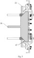
- FIG. 5 depicts a top perspective view of the vehicle display height adjustment assembly with the inner bracket cover 13, outer bracket cover 14, and display cover 30 removed. It best demonstrates how the bracket 16 is configured to fit within a receiving cavity 47 of the bracket support members 22. The bracket support members 22 slidably couple the bracket 16 to the display cover 30.
- FIG. 6 depicts an isometric perspective view of one bracket support member 22. Specifically, it illustrates the geometry of the receiving cavity 47 designed to engage the bracket 16. It also shows the side wall 45 that the tolerance biasing elements 28 abuts as seen in FIG. 3 .
- FIG. 7 depicts a top perspective view of the vehicle display height adjustment assembly with the bracket 16 removed.
- Each fastening member 36 includes a locking lever 37.
- FIG. 7 illustrates the locking levers 37 in an open position. When the locking levers 37 are in an open position, the fastening members 36 are unengaged and enable the movement of the adjustment mechanisms 20 and the display 10.
- one locking lever 37 is rotated inwards in a first direction A, it shifts to a closed position and the respective fastening member 36 is engaged.
- the locking force provided by the fastening member 36 prevents movement of the display cover 30. From the closed position, the locking lever 37 is rotated in a second direction B to the open position.
- FIG. 8-10 illustrate front perspective views of the adjustment mechanisms 20, and specifically emphasizes the operation of the adjustment mechanisms 20.
- Each adjustment mechanism 20 cooperates with the bracket 16 to adjust the display cover 30 in relation to the bracket 16.
- FIG. 8 depicts the adjustment mechanisms 20 in a locked state at a first position.
- an adjustment pin 50 is biased by the biasing member 44 into a corresponding geometry on an adjustment rod 48.
- the adjustment rod 48 may be either integrally connected to the bracket 16 or detachably coupled to the bracket 16. The cooperation between the adjustment pin 50 and the adjustment rod 48 restricts movement of the adjustment mechanism 20 locking it into the first position. This in turn retains the display system 10 into a first position.
- FIG. 9 illustrates the adjustment mechanism in an unlocked state at the first position.
- a second force 54 as shown in FIG. 10 may then be applied to the display cover 30 to move each adjustment mechanism 20 to a second desired position.
- the biasing member 44 is released to allow the adjustment pin 50 to reengage the adjustment rod 48.
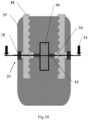
- FIG. 10 illustrates the adjustment mechanism 20 in a locked state at the second position after a downward translation of the display 10.
- the first force 52 on each lever 38 has been removed and the respective adjustment pins 50 are biased into the corresponding geometry on the adjustment rod 48.
- the adjustment mechanisms 20 and display system 10 are now retained at the second position.
- FIG. 11a and 11b illustrate a top perspective view of the adjustment mechanism 20, and specifically emphasizes the operation of the adjustment mechanisms 20.
- FIG. 11a depicts the adjustment mechanisms 20 in a locked state
- FIG. 11b depicts the adjustment mechanisms 20 in an unlocked state.
- the biasing members 44 cooperate with the levers 38 and the dividing wall 46.
- a first force 52 is applied to the levers 38 the biasing members 44 are compressed against the dividing wall 46. As previously described, this then enables the adjustment mechanisms 20 and display 10 to be translated to a desired height position.
- the display system 10 may be adjustable in height with a two hand adjustment. I.e. the driver may hold the display screen 11 encased within the bezel 12 in his hands, when a height adjustment is conducted.
- the fixation via the eccentric fastening members 36 needs to be loosen by rotating the locking members 37.
- the driver may push the button-like levers 38 on the left and on the right sides. This pushes the adjustment pins 50 out of their positions within recesses provided by the respective adjustment rods 48 and the display screen 11 may be moved vertically.
- the bracket 16 is guided between a dovetail geometry provided by the bracket support members 22.
- the driver stops pushing the button-like levers 38, moves the display screen 11 slightly upwards or downwards until the adjustment pins 50 enter complementary recesses provided by the respective adjustment rods 48.
- the fastening members 36 need to be tighten via the locking members 37. During the tightening, the driver no longer has to hold the display screen 11 encased within the bezel 12.
Landscapes
- Engineering & Computer Science (AREA)
- Mechanical Engineering (AREA)
- Fittings On The Vehicle Exterior For Carrying Loads, And Devices For Holding Or Mounting Articles (AREA)
- Devices For Indicating Variable Information By Combining Individual Elements (AREA)
- Instrument Panels (AREA)
Description
- The present disclosure relates to a vehicle display system.
- Vehicles are increasingly moving toward implementation of cameras and electronic display systems to provide additional safety and security systems. The placement of such a display system needs to be visible to the driver in order to access the information provided and be retained in the event of an impact scenario. Current display systems are not efficient at retaining the respective position of the display system and do not account for differences in driver eye height. Additionally, current display systems require specific tooling to facilitate the adjustment of the display system. This results in the user requiring additional time and difficulty to adjust the display system.
-
US 2019/263327 A1 describes a monitor of a camera-monitor system in a motor vehicle, the monitor comprising: a display mounted in a field of vision of a driver of the motor vehicle;
wherein a vertical position of the monitor is adjustable and does not affect a horizontal position of the monitor; and wherein the vertical position of the monitor is held by both a force fit and a form fit; a spring exerting a force establishing the force fit; a sliding element; a holding element including a slide rail for the sliding element; wherein the sliding element includes a toothing on a first longitudinal side and, on its second longitudinal side lying opposite the first longitudinal side, strikes against a rail; wherein the rail is supported in relation to the holding element by means of springs; the holding element includes a rack lying opposite the toothing of the sliding element; and the slide rail is connected in a horizontally displaceable manner to the holding element. - It is the object of this invention to provide a vehicle display system with height adjustment that overcomes at least some of the drawback of the prior art.
- Said object is solved by a vehicle display system, which comprises: a bracket; at least one bracket support member wherein the bracket support member comprises a receiving cavity to retain the bracket; a display cover coupled to the at least one bracket support member; a display adapter coupled to the display cover; and at least one adjustment mechanism coupled to the display cover, wherein the adjustment mechanism comprises at least one mounting member that couples to the display adapter, wherein the mounting member comprises at least one first bracket element and at least one second bracket element; a lever that is slidably engaged within the first bracket element; and a biasing element supported by the second bracket element; wherein the biasing member cooperates with the lever such that, when a first force is applied to the lever the biasing member is compressed to enable the adjustment mechanism to be translated to a desired position.
- The bracket may be mounted to an attachment component for facilitating coupling to a vehicle directly or indirectly. This attachment component may be configured for driver side and/or passenger side mounting. An example attachment component is describe in
US 63/065,627 with the title "Vehicle Display Retention Assembly" filed on August 14, 2020 - According to the invention it is preferred that the vehicle display system further comprises at least one fastening member for coupling the display adapter to the display cover such that, when the fastening member is loosened, the adjustment mechanism is functional to enable movement of the display cover in relation to the bracket, and, when the fastening member is tightened, the movement of the adjustment mechanism is restricted.
- It is proposed that each fastening member comprises a locking lever, with the locking lever preferably being rotatable between an open position loosening the fastening member and a closed position tightening the fastening member, and/or each fastening member comprising an eccentric screw.
- Preferred embodiments of the vehicle display system according to the invention further comprise at least one first gasket located between the bracket support member and the display cover, and/or at least second first gasket located between the display cover and the display adapter, with preferably each second gasket being designed to fit on one fastening member.
- It is also proposed that at least one tolerance biasing element is located between the display cover and the first gasket, preferably arranged on either the inside or outside of the bracket support member.
- Further, it is proposed that the tolerance biasing element cooperates with a side wall of the bracket support member and the display cover to ensure alignment of the bracket support member, and/or the tolerance biasing element cooperates with the display adapter and the bracket support member to ensure a proper mounted alignment.
- According to the invention it is also proposed that the adjustment mechanism further comprises an adjustment pin that cooperates with the biasing element; and an adjustment rod that cooperates with the adjustment pin, with the adjustment rod preferably being integrally connected to the bracket or detachably coupled to the bracket.
- In addition, embodiments of the present invention can be further characterized by a dividing wall, wherein the cover has the dividing wall as a physical barrier separating two adjustment mechanisms, and/or the biasing members of two adjustment mechanisms cooperate with the respective levers and the dividing wall such that, when a first force is applied to the levers the biasing members are compressed against the dividing wall to enable the adjustment mechanisms and a display screen to be translated to a desired height position, and/or, per adjustment mechanism, the lever engages and compresses the biasing member against the dividing wall for translating the adjustment pin out of the corresponding geometry of the adjustment rod.
- Still further, it is proposed that there are two or four adjustment mechanisms, with each fastening member preferably cooperating with one adjustment mechanism retaining the location of the display cover in relation to the bracket, when the fastening member is in a locked position.
- It is preferred according to the invention that there are at least two bracket support members between which the bracket can be vertically moved for a height adjustment, with preferably the bracket support members providing a dovetail guiding.
- It is also proposed that there are four bracket support members located in proximity to the four corners of the bracket, and/or there are two first gaskets located between each bracket support member and the display cover, with preferably the first gaskets being injected into the display system during assembly.
- Embodiments of the invention can further comprise at least one display screen coupled with the display adapter; wherein preferably a bezel encases the display screen.
- In addition, it is proposed that the display screen comprises bonded glass.
- Still further, it is proposed that the display adapter and/or the bracket is constructed from aluminum or a high-tech plastic material.
- An electromagnetic shield adapter unit for cooling electric components of the vehicle display system, in particular its electronic control unit, may also be used, for example in form of the unit describe in
US 63/065,606 with the title "Electromagnetic Shielding (EMC) Adapter within Vehicle Display Unit" filed on August 14, 2020 - The present invention will be better understood from the following description of preferred embodiments which are described with respect to the accompanying drawings, in which:
- FIG. 1a
- depicts an isometric perspective view of a vehicle display system,
- FIG. 1b
- depicts the vehicle display system mounted to an A-pillar of a vehicle,
- FIG. 2
- depicts an exploded view of a vehicle display height adjustment assembly,
- FIG. 3
- depicts a front perspective view of the vehicle display height adjustment assembly,
- FIG. 4
- depicts a top perspective view of the vehicle display height adjustment assembly,
- FIG. 5
- depicts a top perspective view of the vehicle display height adjustment assembly with the covers removed,
- FIG. 6
- depicts an isometric perspective view of a bracket support member. and covers removed,
- FIG. 7
- depicts a top perspective view of the vehicle display height adjustment assembly with the bracket,
- FIG. 8
- depicts a front perspective view of the vehicle display height adjustment assembly emphasizing the height adjustment mechanism in a relaxed position,
- FIG. 9
- depicts a front perspective view of the vehicle display height adjustment assembly emphasizing the height adjustment mechanism in an engaged position,
- FIG. 10
- depicts a front perspective view of the vehicle display height adjustment assembly emphasizing the height adjustment mechanism in an adjusted position,
- FIG. 11a
- depicts a top perspective view of the vehicle display height adjustment assembly emphasizing the height adjustment mechanism in a relaxed position,
- FIG. 11b
- depicts a top perspective view of the vehicle display height adjustment assembly emphasizing the height adjustment mechanism in an engaged position.
- The following description is merely exemplary in nature and is not intended to limit the present disclosure, application, or uses. It should be understood that throughout the drawings, corresponding reference numerals indicate like or corresponding parts and features.
-
FIG. 1a depicts an isometric perspective view of adisplay system 10 for avehicle 1. Thedisplay system 10 comprises adisplay screen 11 and abezel 12. Thebezel 12 surrounds thedisplay screen 11, wherein thedisplay screen 11 is a form of bonded glass. Further, thebezel 12 may be configured to accept paint to alter the appearance of thebezel 12. Thedisplay system 10 further comprises aninner bracket cover 13 and anouter bracket cover 14. Theouter bracket cover 14 andinner bracket cover 13 cooperate to provide protection and improved appearance for abracket 16, shown inFIG. 2 . Thebracket 16 provides a means for attachment of thedisplay system 10 to avehicle 1. Thebracket 16 may be mounted to an attachment component for facilitating coupling to the vehicle directly or indirectly. This attachment component may be configured for driver side and/or passenger side mounting. An example attachment component is describe inUS 63/065,627 with the title "Vehicle Display Retention Assembly" filed on August 14, 2020 FIG. 1b thedisplay system 10 mounts to a vehicle A-pillar. In other configurations the display system may mount to a vehicle door, a windshield, a grab bar attached to the vehicle, or any other vehicle structure. -
FIG. 1b depicts thedisplay system 10 mounted to the A-pillar of thevehicle 1, with thedisplay system 10 being adjustable up to 75mm while maintaining crash safety requirements. The adjustability of this design enables movement of the perpendicular of thedisplay system 10 to align with the eyes of the driver (not shown). This design also allows for the adjustment of thedisplay system 10 without additional tooling such as screw drivers, hammers, hex keys, or similar devices. -
FIG. 2 depicts an exploded view of thedisplay system 10 emphasizing a vehicle display height adjustment assembly. Theinner bracket cover 13 and theouter bracket cover 14 cooperate with thebracket 16. Thebracket 16 facilitates the connection between thedisplay system 10 and thevehicle 1 by attaching to the A-pillar. Thebracket 16 is coupled to adisplay cover 30 via at least twobracket support members 22. In this configuration, there are fourbracket support members 22 located in proximity to the four corners of thebracket 16. Thebracket 16 is designed to be slidably coupled within thebracket support members 22. Thebracket support members 22 are coupled to thedisplay cover 30 and adisplay adapter 34 via at least onebracket support fastener 24. In this configuration, twobracket support fasteners 24 are used for eachbracket support member 22 and are located in opposite corners of thebracket support member 22. - In this configuration the
display adapter 34 and thebracket 16 are constructed from aluminum or a high-tech plastic material. These material ensure forces applied to the display system are strucutrally received and contained by thedisplay adaptor 34 or thebracket 16. - An electromagnetic shield adapter unit for cooling electric components of the vehicle display system, in particular its electronic control unit, may be used, for example in form of the unit describe in
US 63/065,606 with the title "Electromagnetic Shielding (EMC) Adapter within Vehicle Display Unit" filed on August 14, 2020 - At least one
first gasket 26 is located between thebracket support member 22 and thedisplay cover 30. Eachfirst gasket 26 reduces system vibration, and may seal the system to inhibit the transfer of contaminants. In this configuration twofirst gaskets 26 are located between eachbracket support member 22 and thedisplay cover 30. In this configuration thefirst gaskets 26 are injected into thedisplay system 10 during assembly. In other variations thefirst gaskets 26 may be incorporated into thedisplay system 10 via other means during assembly as well. - Located between the
display cover 30 and thefirst gaskets 26 is at least onetolerance biasing element 28. In this configuration there is onetolerance biasing element 28 with eachbracket support member 22. In other configurations there may be more than onetolerance biasing element 28. Eachtolerance biasing element 28 may be located on either the inside or outside of thebracket support member 22. - The
tolerance biasing elements 28 cooperate with aside wall 45, seeFIG. 5 , of thebracket support member 22 and thedisplay cover 30 to ensure alignment of thebracket support member 22. In other configurations thetolerance biasing element 28 may cooperate with thedisplay adapter 34 and thebracket support member 22 to ensure a proper mounted alignment. - Additionally, an
adjustment mechanism 20 is coupled to thedisplay cover 30 anddisplay adapter 34 via at least oneadjustment mechanism fastener 18 and positioned between thedisplay cover 30 and thebracket 16. The height of thedisplay system 10 may be adjusted by the cooperation of theadjustment mechanism 20 with thedisplay cover 30 and thebracket 16. In this configuration there are twoadjustment mechanisms 20. However, other designs may have more orless adjustment mechanisms 20 to meet design requirements. - The
display adapter 34 is coupled to thedisplay cover 30. At least onefastening member 36 cooperates with thedisplay adapter 34 and thedisplay cover 30. When thefastening member 36 is loosened, theadjustment mechanism 20 is functional to enable movement of thedisplay cover 30 in relation to thebracket 16. Whereas, when thefastening member 36 is tightened, the movement of theadjustment mechanism 20 is restricted. In this configuration there are twofastening members 36, which are eccentric screws. Alternatively, there can be more or less of these in other configurations to comply with design requirements. - Between the
display cover 30 and thedisplay adapter 34 is at least onesecond gasket 32 designed to fit on thefastening member 36. Eachsecond gasket 32 is able to reduce vibration, and seal the system to inhibit the transfer of contaminants. In this configuration there are twosecond gaskets 32, but in other configurations there may be more or less to meet design requirements. -
FIG. 3 depicts a front view of the vehicle display height adjustment assembly. Thebracket 16 is designed to be positioned between thebracket support members 22 and be slidably coupled. In this configuration thetolerance biasing elements 28 are located on the outside of the twobracket support members 22 on the left side and on the inside of the twobracket support members 22 on the right side. In other configurations thetolerance biasing elements 28 may be located on the inside or outside of allbracket support members 22. Thetolerance biasing elements 28 shift thebracket support members 22 onto a support area in thedisplay adapter 34. The support areas are in parallel within a specific range to decrease the tolerance range of thebracket support members 22 to each other. This prevents the system from jamming, and ensures it is robust and of high quality. - In this configuration the vehicle display height adjustment assembly contains two
adjustment mechanisms 20. Bothadjustment mechanisms 20 are engaged simultaneously in order to adjust thedisplay system 10. This ensures that a user will need to use both hands to engage bothadjustment mechanisms 20 and provide the required support to inhibit thedisplay system 10 slipping into an unintended end position. - Each
adjustment mechanism 20 is comprised of alever 38, afirst bracket element 40, asecond bracket element 42, and a biasingmember 44. Thefirst bracket element 40 and thesecond bracket element 42 are coupled to thedisplay adapter 34 via fouradjustment mechanism fasteners 18 for each bracket. Thefirst bracket element 40 supports thelever 38 and acts as a guide for when thelever 38 is slidably engaged. Thesecond bracket element 42 supports the biasingmember 44. In this configuration thesecond bracket element 42 acts as a guide for the biasingmember 44. In other configurations the biasingmember 44 and/orsecond bracket element 42 may be coupled to a dividingwall 46 shown inFIG. 4 . - The
fastening member 36 is located near theadjustment mechanism 20 and cooperates with theadjustment mechanism 20 to assist in retaining the location of thedisplay cover 30 in relation to thebracket 16. When thefastening member 36 is in a locked position, thefastening member 36 provides sufficient force to retaindisplay adapter 34 to thebracket 16. - In
FIG. 4 a top perspective view of the vehicle display height adjustment assembly is shown. Theinner bracket cover 13 and theouter bracket cover 14 cooperate to cover thebracket 16. Theadjustment mechanism 20 cooperates with thebracket 16, thedisplay adapter 34, and thedisplay cover 30 to adjust the height of thedisplay system 10. Thecover 30 has the dividingwall 46 which in this form provides a physical barrier separating the twoadjustment mechanisms 20. -
FIG. 5 depicts a top perspective view of the vehicle display height adjustment assembly with theinner bracket cover 13,outer bracket cover 14, and display cover 30 removed. It best demonstrates how thebracket 16 is configured to fit within a receivingcavity 47 of thebracket support members 22. Thebracket support members 22 slidably couple thebracket 16 to thedisplay cover 30. -
FIG. 6 depicts an isometric perspective view of onebracket support member 22. Specifically, it illustrates the geometry of the receivingcavity 47 designed to engage thebracket 16. It also shows theside wall 45 that thetolerance biasing elements 28 abuts as seen inFIG. 3 . -
FIG. 7 depicts a top perspective view of the vehicle display height adjustment assembly with thebracket 16 removed. Each fasteningmember 36 includes a lockinglever 37.FIG. 7 illustrates the locking levers 37 in an open position. When the locking levers 37 are in an open position, thefastening members 36 are unengaged and enable the movement of theadjustment mechanisms 20 and thedisplay 10. When one lockinglever 37 is rotated inwards in a first direction A, it shifts to a closed position and therespective fastening member 36 is engaged. When saidfastening member 36 is engaged, the locking force provided by thefastening member 36, prevents movement of thedisplay cover 30. From the closed position, the lockinglever 37 is rotated in a second direction B to the open position. -
FIG. 8-10 illustrate front perspective views of theadjustment mechanisms 20, and specifically emphasizes the operation of theadjustment mechanisms 20. Eachadjustment mechanism 20 cooperates with thebracket 16 to adjust thedisplay cover 30 in relation to thebracket 16. -
FIG. 8 depicts theadjustment mechanisms 20 in a locked state at a first position. In the first position, peradjustment mechanism 20, anadjustment pin 50 is biased by the biasingmember 44 into a corresponding geometry on anadjustment rod 48. Theadjustment rod 48 may be either integrally connected to thebracket 16 or detachably coupled to thebracket 16. The cooperation between theadjustment pin 50 and theadjustment rod 48 restricts movement of theadjustment mechanism 20 locking it into the first position. This in turn retains thedisplay system 10 into a first position. - As depicted in
FIG. 7 , when the lockinglever 37 of thefastening member 36 is in an upright position, thefastening member 36 is unengaged and enables theadjustment mechanism 20 to be engaged and the translation of thedisplay 10. Afirst force 52 is applied to thelever 38. The lever engages and compresses the biasingmember 44 against the dividingwall 46 translating theadjustment pin 50 out of the corresponding geometry of theadjustment rod 48 This disengages theadjustment pin 50 from theadjustment rod 48 and transitions theadjustment mechanism 20 into an unlocked state in the first position. -
FIG. 9 illustrates the adjustment mechanism in an unlocked state at the first position. Asecond force 54 as shown inFIG. 10 , may then be applied to thedisplay cover 30 to move eachadjustment mechanism 20 to a second desired position. When thefirst force 52 on thelever 38 is disengaged, the biasingmember 44 is released to allow theadjustment pin 50 to reengage theadjustment rod 48.FIG. 10 illustrates theadjustment mechanism 20 in a locked state at the second position after a downward translation of thedisplay 10. In this figure, thefirst force 52 on eachlever 38 has been removed and the respective adjustment pins 50 are biased into the corresponding geometry on theadjustment rod 48. Theadjustment mechanisms 20 anddisplay system 10 are now retained at the second position. -
FIG. 11a and 11b illustrate a top perspective view of theadjustment mechanism 20, and specifically emphasizes the operation of theadjustment mechanisms 20.FIG. 11a depicts theadjustment mechanisms 20 in a locked state, andFIG. 11b depicts theadjustment mechanisms 20 in an unlocked state. As shown, the biasingmembers 44 cooperate with thelevers 38 and the dividingwall 46. When afirst force 52 is applied to thelevers 38 the biasingmembers 44 are compressed against the dividingwall 46. As previously described, this then enables theadjustment mechanisms 20 anddisplay 10 to be translated to a desired height position. - In the following an exemplary display height adjustment is described:
Thedisplay system 10 may be adjustable in height with a two hand adjustment. I.e. the driver may hold thedisplay screen 11 encased within thebezel 12 in his hands, when a height adjustment is conducted. In a first step, the fixation via theeccentric fastening members 36 needs to be loosen by rotating the lockingmembers 37. Then the driver may push the button-like levers 38 on the left and on the right sides. This pushes the adjustment pins 50 out of their positions within recesses provided by therespective adjustment rods 48 and thedisplay screen 11 may be moved vertically. During said movement, thebracket 16 is guided between a dovetail geometry provided by thebracket support members 22. When an end-position is roughly found, the driver stops pushing the button-like levers 38, moves thedisplay screen 11 slightly upwards or downwards until the adjustment pins 50 enter complementary recesses provided by therespective adjustment rods 48. As a last step, thefastening members 36 need to be tighten via the lockingmembers 37. During the tightening, the driver no longer has to hold thedisplay screen 11 encased within thebezel 12. - The foregoing description of various preferred embodiments have been presented for purposes of illustration and description. It is not intended to be exhaustive or to limit the disclosure to the precise forms disclosed, and obviously many modifications and variations are possible in light of the above teaching. The example embodiments, as described above, were chosen and described in order to best explain the principles of the disclosure and its practical application to thereby enable others skilled in the art to best utilize the disclosure in various embodiments and with various modifications as are suited to the particular use contemplated.
-
- 1 - Vehicle
- 10 - Display System
- 11 - Display Screen
- 12 - Bezel
- 13 - Inner Bracket Cover
- 14 - Outer Bracket Cover
- 16 - Bracket
- 18 - Adjustment Mechanism Fasteners
- 20 - Adjustment Mechanism
- 22 - Bracket Support Member
- 24 - Bracket Support Fasteners
- 26 - First Gasket
- 28 - Tolerance Biasing Element
- 30 - Display Cover
- 32 - Second Gasket
- 34 - Display Adapter
- 36 - Fastening Member
- 37 - Locking Lever
- 38 - Lever
- 40 - First bracket element
- 42 - Second bracket element
- 44 - Biasing Member
- 45 - Side Wall
- 46 - Dividing Wall
- 47 - Receiving Cavity
- 48 - Adjustment rod
- 50 - Adjustment Pin
- 52 - First Force
- 54 - Second Force
- A - First Direction
- B - Second Direction
Claims (14)
- A vehicle display system (10) comprises:• a bracket (16);• at least one bracket support member (22) wherein the bracket support member (22) comprises a receiving cavity (47) to retain the bracket (16);• a display cover (30) coupled to the at least one bracket support member (22);• a display adapter (34) coupled to the display cover (30); and• at least one adjustment mechanism (20) coupled to the display cover (30),wherein the adjustment mechanism (20) comprises• at least one mounting member that couples to the display adapter (34), wherein the mounting member comprises at least one first bracket element (40) and at least one second bracket element (42);• a lever (38) that is slidably engaged within the first bracket element (40); and• a biasing element (44) supported by the second bracket element (42),wherein the biasing member (44) cooperates with the lever (38) such that, when a first force (52) is applied to the lever (38) the biasing member (44) is compressed to enable the adjustment mechanism (20) to be translated to a desired position.
- The vehicle display system of claim 1, further comprising
at least one fastening member (36) for coupling the display adapter (34) to the display cover (30) such that, when the fastening member (36) is loosened, the adjustment mechanism (20) is functional to enable movement of the display cover (30) in relation to the bracket (16), and, when the fastening member (36) is tightened, the movement of the adjustment mechanism (20) is restricted. - The vehicle display system of claim 2, whereineach fastening member (36) comprises a locking lever (37), with the locking lever (37) preferably being rotatable between an open position loosening the fastening member (36) and a closed position tightening the fastening member (36), and/oreach fastening member (36) comprising an eccentric screw.
- The vehicle display system of any one of the preceding claims, further comprisingat least one first gasket (26) located between the bracket support member (22) and the display cover (30), and/orat least second first gasket (32) located between the display cover (30) and the display adapter (34), with preferably each second gasket (32) being designed to fit on one fastening member (36).
- The vehicle display system of claim 4, wherein
at least one tolerance biasing element (28) is located between the display cover (30) and the first gasket (26), preferably arranged on either the inside or outside of the bracket support member (22). - The vehicle display system of claim 5, whereinthe tolerance biasing element (28) cooperates with a side wall (45) of the bracket support member (22) and the display cover (30) to ensure alignment of the bracket support member (22), and/orthe tolerance biasing element (28) cooperates with the display adapter (34) and the bracket support member (22) to ensure a proper mounted alignment.
- The vehicle display system of any one of the preceding claims, wherein
the adjustment mechanism (20) further comprises• an adjustment pin (50) that cooperates with the biasing element (44); and• an adjustment rod (48) that cooperates with the adjustment pin (50), with the adjustment rod (48) preferably being integrally connected to the bracket (16) or detachably coupled to the bracket (16). - The vehicle display system of any one of the preceding claims, further comprising a dividing wall (46), whereinthe cover (30) has the dividing wall (46) as a physical barrier separating two adjustment mechanisms (20), and/orthe biasing members (44) of two adjustment mechanisms (20) cooperate with the respective levers (38) and the dividing wall (46) such that, when a first force (52) is applied to the levers (38) the biasing members (44) are compressed against the dividing wall (46) to enable the adjustment mechanisms (20) and a display screen (11) to be translated to a desired height position, and/or,per adjustment mechanism (20), the lever (38) engages and compresses the biasing member (44) against the dividing wall (46) for translating the adjustment pin (50) out of the corresponding geometry of the adjustment rod (48).
- The vehicle display system of any one of the preceding claims, wherein
there are two or four adjustment mechanisms (20), with each fastening member (36) preferably cooperating with one adjustment mechanism (20) retaining the location of the display cover (30) in relation to the bracket (16), when the fastening member (36) is in a locked position. - The vehicle display system of any one of the preceding claims, wherein
there are at least two bracket support members (22) between which the bracket (16) can be vertically moved for a height adjustment, with preferably the bracket support members (22) providing a dovetail guiding. - The vehicle display system of any one of the preceding claims, whereinthere are four bracket support members (22) located in proximity to the four corners of the bracket (16), and/orthere are two first gaskets (26) located between each bracket support member (22) and the display cover (30), with preferably the first gaskets (26) being injected into the display system (10) during assembly.
- The vehicle display system of any one of the preceding claims, further comprising at least one display screen (11) coupled with the display adapter (34); wherein preferably a bezel (12) encases the display screen (11).
- The vehicle display system of claim 12, wherein
the display screen comprises bonded glass. - The vehicle display system of any one of the preceding claims, wherein
the display adapter (34) and/or the bracket (16) is constructed from aluminum or a high-tech plastic material.
Applications Claiming Priority (2)
| Application Number | Priority Date | Filing Date | Title |
|---|---|---|---|
| DE102020130777 | 2020-11-20 | ||
| PCT/EP2021/081637 WO2022106335A1 (en) | 2020-11-20 | 2021-11-15 | Vehicle display system with height adjustment |
Publications (2)
| Publication Number | Publication Date |
|---|---|
| EP4217238A1 EP4217238A1 (en) | 2023-08-02 |
| EP4217238B1 true EP4217238B1 (en) | 2025-01-01 |
Family
ID=78709467
Family Applications (1)
| Application Number | Title | Priority Date | Filing Date |
|---|---|---|---|
| EP21811030.2A Active EP4217238B1 (en) | 2020-11-20 | 2021-11-15 | Vehicle display system with height adjustment |
Country Status (4)
| Country | Link |
|---|---|
| US (1) | US12337765B2 (en) |
| EP (1) | EP4217238B1 (en) |
| CN (1) | CN116472201B (en) |
| WO (1) | WO2022106335A1 (en) |
Families Citing this family (1)
| Publication number | Priority date | Publication date | Assignee | Title |
|---|---|---|---|---|
| EP4717530A1 (en) * | 2024-09-27 | 2026-04-01 | Volvo Truck Corporation | Curtain airbag system, associated vehicle and method |
Family Cites Families (10)
| Publication number | Priority date | Publication date | Assignee | Title |
|---|---|---|---|---|
| US5305381A (en) | 1992-11-09 | 1994-04-19 | Wang Chin Y | Cradle for telephone |
| CN101335051B (en) * | 2007-06-29 | 2010-10-06 | 群康科技(深圳)有限公司 | display device |
| CN202686184U (en) * | 2012-08-24 | 2013-01-23 | 成都弥荣科技发展有限公司 | Dustproof support of adjustable suspension type automobile detection displayer |
| FR3012566B1 (en) * | 2013-10-30 | 2016-05-27 | Peugeot Citroen Automobiles Sa | APPARATUS SUPPORT NOMADE ADJUSTABLE IN HEIGHT |
| WO2020018965A1 (en) * | 2018-07-19 | 2020-01-23 | Hoyda Serge | System and process for viewing in blind spots |
| US9358929B1 (en) * | 2015-01-21 | 2016-06-07 | Ford Global Technologies, Llc | Interior trim electronic device holder |
| TWM516683U (en) * | 2015-09-23 | 2016-02-01 | 信錦企業股份有限公司 | Lifting structure with adjustable bearing capacity |
| DE102016221434B4 (en) * | 2016-11-01 | 2020-01-16 | Continental Automotive Gmbh | Monitor of a camera monitor system |
| KR101846730B1 (en) * | 2016-11-01 | 2018-04-06 | 현대자동차주식회사 | Mounting Structure for Image display apparatus |
| US10634924B2 (en) * | 2017-12-19 | 2020-04-28 | Ford Global Technologies, Llc | Display projector operation |
-
2021
- 2021-11-15 CN CN202180077930.5A patent/CN116472201B/en active Active
- 2021-11-15 EP EP21811030.2A patent/EP4217238B1/en active Active
- 2021-11-15 WO PCT/EP2021/081637 patent/WO2022106335A1/en not_active Ceased
- 2021-11-15 US US18/250,243 patent/US12337765B2/en active Active
Also Published As
| Publication number | Publication date |
|---|---|
| EP4217238A1 (en) | 2023-08-02 |
| CN116472201A (en) | 2023-07-21 |
| US12337765B2 (en) | 2025-06-24 |
| CN116472201B (en) | 2024-01-23 |
| WO2022106335A1 (en) | 2022-05-27 |
| US20240017678A1 (en) | 2024-01-18 |
Similar Documents
| Publication | Publication Date | Title |
|---|---|---|
| EP3489090B1 (en) | Camera unit | |
| US7255401B2 (en) | Automobile headrest | |
| EP4217238B1 (en) | Vehicle display system with height adjustment | |
| RU2697641C2 (en) | Electronic device holder (versions) and electric connector for it | |
| CN210822004U (en) | Compartment cover locking device, compartment and truck | |
| US6913303B2 (en) | Mounting system for a motor vehicle | |
| US10883649B2 (en) | Monitor of a camera-monitor system | |
| EP2300259A1 (en) | Display screen mount | |
| US10023127B2 (en) | Vehicle interior component | |
| CN1274188C (en) | Assembly cabinet | |
| US20170101043A1 (en) | Driving device for vertically movable waist bar of vehicle | |
| DE102007004446B4 (en) | Dashboard of a vehicle for a mobile computer | |
| EP4164922B1 (en) | Vehicle display system and vehicle display retention system | |
| JP3377017B2 (en) | Automotive door frame assembly structure | |
| CN221162508U (en) | Roof luggage rack and locking device thereof | |
| CN218716450U (en) | Sunshade curtain structure of full-automatic driving vehicle cab | |
| CN216059836U (en) | Three-dimensional adjustable wooden damping drawer | |
| KR102478817B1 (en) | Sliding type glove box with detachable stopper | |
| US20090229390A1 (en) | Locking and unlocking device | |
| JP2008273283A (en) | Push type knob device | |
| EP4600058A1 (en) | Assembly for a vehicle | |
| US20240326692A1 (en) | Rear-view assembly for vehicles | |
| KR200157250Y1 (en) | Roof carrier of a car | |
| CN220199439U (en) | Unmanned delivery express delivery car | |
| CN215851048U (en) | Screw cover plate for vehicle |
Legal Events
| Date | Code | Title | Description |
|---|---|---|---|
| STAA | Information on the status of an ep patent application or granted ep patent |
Free format text: STATUS: UNKNOWN |
|
| STAA | Information on the status of an ep patent application or granted ep patent |
Free format text: STATUS: THE INTERNATIONAL PUBLICATION HAS BEEN MADE |
|
| PUAI | Public reference made under article 153(3) epc to a published international application that has entered the european phase |
Free format text: ORIGINAL CODE: 0009012 |
|
| STAA | Information on the status of an ep patent application or granted ep patent |
Free format text: STATUS: REQUEST FOR EXAMINATION WAS MADE |
|
| 17P | Request for examination filed |
Effective date: 20230424 |
|
| AK | Designated contracting states |
Kind code of ref document: A1 Designated state(s): AL AT BE BG CH CY CZ DE DK EE ES FI FR GB GR HR HU IE IS IT LI LT LU LV MC MK MT NL NO PL PT RO RS SE SI SK SM TR |
|
| DAV | Request for validation of the european patent (deleted) | ||
| DAX | Request for extension of the european patent (deleted) | ||
| GRAP | Despatch of communication of intention to grant a patent |
Free format text: ORIGINAL CODE: EPIDOSNIGR1 |
|
| STAA | Information on the status of an ep patent application or granted ep patent |
Free format text: STATUS: GRANT OF PATENT IS INTENDED |
|
| INTG | Intention to grant announced |
Effective date: 20240703 |
|
| GRAS | Grant fee paid |
Free format text: ORIGINAL CODE: EPIDOSNIGR3 |
|
| GRAA | (expected) grant |
Free format text: ORIGINAL CODE: 0009210 |
|
| STAA | Information on the status of an ep patent application or granted ep patent |
Free format text: STATUS: THE PATENT HAS BEEN GRANTED |
|
| AK | Designated contracting states |
Kind code of ref document: B1 Designated state(s): AL AT BE BG CH CY CZ DE DK EE ES FI FR GB GR HR HU IE IS IT LI LT LU LV MC MK MT NL NO PL PT RO RS SE SI SK SM TR |
|
| REG | Reference to a national code |
Ref country code: GB Ref legal event code: FG4D |
|
| REG | Reference to a national code |
Ref country code: DE Ref legal event code: R096 Ref document number: 602021024372 Country of ref document: DE |
|
| REG | Reference to a national code |
Ref country code: CH Ref legal event code: EP |
|
| P01 | Opt-out of the competence of the unified patent court (upc) registered |
Free format text: CASE NUMBER: APP_68015/2024 Effective date: 20241224 |
|
| REG | Reference to a national code |
Ref country code: IE Ref legal event code: FG4D |
|
| REG | Reference to a national code |
Ref country code: LT Ref legal event code: MG9D |
|
| REG | Reference to a national code |
Ref country code: NL Ref legal event code: MP Effective date: 20250101 |
|
| REG | Reference to a national code |
Ref country code: AT Ref legal event code: MK05 Ref document number: 1755939 Country of ref document: AT Kind code of ref document: T Effective date: 20250101 |
|
| PG25 | Lapsed in a contracting state [announced via postgrant information from national office to epo] |
Ref country code: NL Free format text: LAPSE BECAUSE OF FAILURE TO SUBMIT A TRANSLATION OF THE DESCRIPTION OR TO PAY THE FEE WITHIN THE PRESCRIBED TIME-LIMIT Effective date: 20250101 |
|
| PG25 | Lapsed in a contracting state [announced via postgrant information from national office to epo] |
Ref country code: FI Free format text: LAPSE BECAUSE OF FAILURE TO SUBMIT A TRANSLATION OF THE DESCRIPTION OR TO PAY THE FEE WITHIN THE PRESCRIBED TIME-LIMIT Effective date: 20250101 |
|
| PG25 | Lapsed in a contracting state [announced via postgrant information from national office to epo] |
Ref country code: PL Free format text: LAPSE BECAUSE OF FAILURE TO SUBMIT A TRANSLATION OF THE DESCRIPTION OR TO PAY THE FEE WITHIN THE PRESCRIBED TIME-LIMIT Effective date: 20250101 |
|
| PG25 | Lapsed in a contracting state [announced via postgrant information from national office to epo] |
Ref country code: ES Free format text: LAPSE BECAUSE OF FAILURE TO SUBMIT A TRANSLATION OF THE DESCRIPTION OR TO PAY THE FEE WITHIN THE PRESCRIBED TIME-LIMIT Effective date: 20250101 |
|
| PG25 | Lapsed in a contracting state [announced via postgrant information from national office to epo] |
Ref country code: NO Free format text: LAPSE BECAUSE OF FAILURE TO SUBMIT A TRANSLATION OF THE DESCRIPTION OR TO PAY THE FEE WITHIN THE PRESCRIBED TIME-LIMIT Effective date: 20250401 Ref country code: IS Free format text: LAPSE BECAUSE OF FAILURE TO SUBMIT A TRANSLATION OF THE DESCRIPTION OR TO PAY THE FEE WITHIN THE PRESCRIBED TIME-LIMIT Effective date: 20250501 |
|
| PG25 | Lapsed in a contracting state [announced via postgrant information from national office to epo] |
Ref country code: HR Free format text: LAPSE BECAUSE OF FAILURE TO SUBMIT A TRANSLATION OF THE DESCRIPTION OR TO PAY THE FEE WITHIN THE PRESCRIBED TIME-LIMIT Effective date: 20250101 |
|
| PG25 | Lapsed in a contracting state [announced via postgrant information from national office to epo] |
Ref country code: LV Free format text: LAPSE BECAUSE OF FAILURE TO SUBMIT A TRANSLATION OF THE DESCRIPTION OR TO PAY THE FEE WITHIN THE PRESCRIBED TIME-LIMIT Effective date: 20250101 Ref country code: PT Free format text: LAPSE BECAUSE OF FAILURE TO SUBMIT A TRANSLATION OF THE DESCRIPTION OR TO PAY THE FEE WITHIN THE PRESCRIBED TIME-LIMIT Effective date: 20250502 |
|
| PG25 | Lapsed in a contracting state [announced via postgrant information from national office to epo] |
Ref country code: GR Free format text: LAPSE BECAUSE OF FAILURE TO SUBMIT A TRANSLATION OF THE DESCRIPTION OR TO PAY THE FEE WITHIN THE PRESCRIBED TIME-LIMIT Effective date: 20250402 Ref country code: BG Free format text: LAPSE BECAUSE OF FAILURE TO SUBMIT A TRANSLATION OF THE DESCRIPTION OR TO PAY THE FEE WITHIN THE PRESCRIBED TIME-LIMIT Effective date: 20250101 |
|
| PG25 | Lapsed in a contracting state [announced via postgrant information from national office to epo] |
Ref country code: AT Free format text: LAPSE BECAUSE OF FAILURE TO SUBMIT A TRANSLATION OF THE DESCRIPTION OR TO PAY THE FEE WITHIN THE PRESCRIBED TIME-LIMIT Effective date: 20250101 |
|
| PG25 | Lapsed in a contracting state [announced via postgrant information from national office to epo] |
Ref country code: CZ Free format text: LAPSE BECAUSE OF FAILURE TO SUBMIT A TRANSLATION OF THE DESCRIPTION OR TO PAY THE FEE WITHIN THE PRESCRIBED TIME-LIMIT Effective date: 20250101 |
|
| PG25 | Lapsed in a contracting state [announced via postgrant information from national office to epo] |
Ref country code: SE Free format text: LAPSE BECAUSE OF FAILURE TO SUBMIT A TRANSLATION OF THE DESCRIPTION OR TO PAY THE FEE WITHIN THE PRESCRIBED TIME-LIMIT Effective date: 20250101 |
|
| REG | Reference to a national code |
Ref country code: DE Ref legal event code: R097 Ref document number: 602021024372 Country of ref document: DE |
|
| PG25 | Lapsed in a contracting state [announced via postgrant information from national office to epo] |
Ref country code: SM Free format text: LAPSE BECAUSE OF FAILURE TO SUBMIT A TRANSLATION OF THE DESCRIPTION OR TO PAY THE FEE WITHIN THE PRESCRIBED TIME-LIMIT Effective date: 20250101 |
|
| PG25 | Lapsed in a contracting state [announced via postgrant information from national office to epo] |
Ref country code: DK Free format text: LAPSE BECAUSE OF FAILURE TO SUBMIT A TRANSLATION OF THE DESCRIPTION OR TO PAY THE FEE WITHIN THE PRESCRIBED TIME-LIMIT Effective date: 20250101 |
|
| PG25 | Lapsed in a contracting state [announced via postgrant information from national office to epo] |
Ref country code: IT Free format text: LAPSE BECAUSE OF FAILURE TO SUBMIT A TRANSLATION OF THE DESCRIPTION OR TO PAY THE FEE WITHIN THE PRESCRIBED TIME-LIMIT Effective date: 20250101 |
|
| PG25 | Lapsed in a contracting state [announced via postgrant information from national office to epo] |
Ref country code: EE Free format text: LAPSE BECAUSE OF FAILURE TO SUBMIT A TRANSLATION OF THE DESCRIPTION OR TO PAY THE FEE WITHIN THE PRESCRIBED TIME-LIMIT Effective date: 20250101 |
|
| PG25 | Lapsed in a contracting state [announced via postgrant information from national office to epo] |
Ref country code: RO Free format text: LAPSE BECAUSE OF FAILURE TO SUBMIT A TRANSLATION OF THE DESCRIPTION OR TO PAY THE FEE WITHIN THE PRESCRIBED TIME-LIMIT Effective date: 20250101 |
|
| PG25 | Lapsed in a contracting state [announced via postgrant information from national office to epo] |
Ref country code: SK Free format text: LAPSE BECAUSE OF FAILURE TO SUBMIT A TRANSLATION OF THE DESCRIPTION OR TO PAY THE FEE WITHIN THE PRESCRIBED TIME-LIMIT Effective date: 20250101 |
|
| PLBE | No opposition filed within time limit |
Free format text: ORIGINAL CODE: 0009261 |
|
| STAA | Information on the status of an ep patent application or granted ep patent |
Free format text: STATUS: NO OPPOSITION FILED WITHIN TIME LIMIT |
|
| 26N | No opposition filed |
Effective date: 20251002 |
|
| PGFP | Annual fee paid to national office [announced via postgrant information from national office to epo] |
Ref country code: DE Payment date: 20251118 Year of fee payment: 5 |
|
| PGFP | Annual fee paid to national office [announced via postgrant information from national office to epo] |
Ref country code: GB Payment date: 20251120 Year of fee payment: 5 |
|
| PGFP | Annual fee paid to national office [announced via postgrant information from national office to epo] |
Ref country code: FR Payment date: 20251125 Year of fee payment: 5 |