EP4216846B1 - Surgical systems with port devices for instrument control - Google Patents
Surgical systems with port devices for instrument control Download PDFInfo
- Publication number
- EP4216846B1 EP4216846B1 EP22787004.5A EP22787004A EP4216846B1 EP 4216846 B1 EP4216846 B1 EP 4216846B1 EP 22787004 A EP22787004 A EP 22787004A EP 4216846 B1 EP4216846 B1 EP 4216846B1
- Authority
- EP
- European Patent Office
- Prior art keywords
- instrument
- port
- instruments
- surgical
- ports
- Prior art date
- Legal status (The legal status is an assumption and is not a legal conclusion. Google has not performed a legal analysis and makes no representation as to the accuracy of the status listed.)
- Active
Links
Images







Classifications
-
- A—HUMAN NECESSITIES
- A61—MEDICAL OR VETERINARY SCIENCE; HYGIENE
- A61B—DIAGNOSIS; SURGERY; IDENTIFICATION
- A61B17/00—Surgical instruments, devices or methods
- A61B17/34—Trocars; Puncturing needles
- A61B17/3417—Details of tips or shafts, e.g. grooves, expandable, bendable; Multiple coaxial sliding cannulas, e.g. for dilating
- A61B17/3421—Cannulas
- A61B17/3423—Access ports, e.g. toroid shape introducers for instruments or hands
-
- A—HUMAN NECESSITIES
- A61—MEDICAL OR VETERINARY SCIENCE; HYGIENE
- A61B—DIAGNOSIS; SURGERY; IDENTIFICATION
- A61B17/00—Surgical instruments, devices or methods
- A61B17/34—Trocars; Puncturing needles
- A61B17/3462—Trocars; Puncturing needles with means for changing the diameter or the orientation of the entrance port of the cannula, e.g. for use with different-sized instruments, reduction ports, adapter seals
-
- A—HUMAN NECESSITIES
- A61—MEDICAL OR VETERINARY SCIENCE; HYGIENE
- A61B—DIAGNOSIS; SURGERY; IDENTIFICATION
- A61B17/00—Surgical instruments, devices or methods
- A61B2017/00017—Electrical control of surgical instruments
- A61B2017/00022—Sensing or detecting at the treatment site
-
- A—HUMAN NECESSITIES
- A61—MEDICAL OR VETERINARY SCIENCE; HYGIENE
- A61B—DIAGNOSIS; SURGERY; IDENTIFICATION
- A61B17/00—Surgical instruments, devices or methods
- A61B2017/00017—Electrical control of surgical instruments
- A61B2017/00022—Sensing or detecting at the treatment site
- A61B2017/00075—Motion
-
- A—HUMAN NECESSITIES
- A61—MEDICAL OR VETERINARY SCIENCE; HYGIENE
- A61B—DIAGNOSIS; SURGERY; IDENTIFICATION
- A61B17/00—Surgical instruments, devices or methods
- A61B2017/00743—Type of operation; Specification of treatment sites
- A61B2017/00818—Treatment of the gastro-intestinal system
-
- A—HUMAN NECESSITIES
- A61—MEDICAL OR VETERINARY SCIENCE; HYGIENE
- A61B—DIAGNOSIS; SURGERY; IDENTIFICATION
- A61B17/00—Surgical instruments, devices or methods
- A61B17/34—Trocars; Puncturing needles
- A61B17/3417—Details of tips or shafts, e.g. grooves, expandable, bendable; Multiple coaxial sliding cannulas, e.g. for dilating
- A61B17/3421—Cannulas
- A61B2017/3445—Cannulas used as instrument channel for multiple instruments
-
- A—HUMAN NECESSITIES
- A61—MEDICAL OR VETERINARY SCIENCE; HYGIENE
- A61B—DIAGNOSIS; SURGERY; IDENTIFICATION
- A61B17/00—Surgical instruments, devices or methods
- A61B17/34—Trocars; Puncturing needles
- A61B17/3462—Trocars; Puncturing needles with means for changing the diameter or the orientation of the entrance port of the cannula, e.g. for use with different-sized instruments, reduction ports, adapter seals
- A61B2017/3466—Trocars; Puncturing needles with means for changing the diameter or the orientation of the entrance port of the cannula, e.g. for use with different-sized instruments, reduction ports, adapter seals for simultaneous sealing of multiple instruments
-
- A—HUMAN NECESSITIES
- A61—MEDICAL OR VETERINARY SCIENCE; HYGIENE
- A61B—DIAGNOSIS; SURGERY; IDENTIFICATION
- A61B17/00—Surgical instruments, devices or methods
- A61B17/34—Trocars; Puncturing needles
- A61B2017/347—Locking means, e.g. for locking instrument in cannula
-
- A—HUMAN NECESSITIES
- A61—MEDICAL OR VETERINARY SCIENCE; HYGIENE
- A61B—DIAGNOSIS; SURGERY; IDENTIFICATION
- A61B34/00—Computer-aided surgery; Manipulators or robots specially adapted for use in surgery
- A61B34/20—Surgical navigation systems; Devices for tracking or guiding surgical instruments, e.g. for frameless stereotaxis
-
- A—HUMAN NECESSITIES
- A61—MEDICAL OR VETERINARY SCIENCE; HYGIENE
- A61B—DIAGNOSIS; SURGERY; IDENTIFICATION
- A61B34/00—Computer-aided surgery; Manipulators or robots specially adapted for use in surgery
- A61B34/30—Surgical robots
-
- A—HUMAN NECESSITIES
- A61—MEDICAL OR VETERINARY SCIENCE; HYGIENE
- A61B—DIAGNOSIS; SURGERY; IDENTIFICATION
- A61B90/00—Instruments, implements or accessories specially adapted for surgery or diagnosis and not covered by any of the groups A61B1/00 - A61B50/00, e.g. for luxation treatment or for protecting wound edges
- A61B90/50—Supports for surgical instruments, e.g. articulated arms
-
- A—HUMAN NECESSITIES
- A61—MEDICAL OR VETERINARY SCIENCE; HYGIENE
- A61B—DIAGNOSIS; SURGERY; IDENTIFICATION
- A61B90/00—Instruments, implements or accessories specially adapted for surgery or diagnosis and not covered by any of the groups A61B1/00 - A61B50/00, e.g. for luxation treatment or for protecting wound edges
- A61B90/50—Supports for surgical instruments, e.g. articulated arms
- A61B90/57—Accessory clamps
Definitions
- the seal housing 7100 of surgical sealing device 7000 can have a variety of configurations.
- the seal housing 7100 has an inner body member 7102 and an outer body member 7104 that is positioned about the inner body member 7102.
- the outer body member can designed so as to extend distally from one end of the inner body member.
- the outer body member can be omitted.
- the seal housing 7301 includes first retention elements 7312 and second retention elements 7314. As shown, the first retention elements 7312 extend outward from the elongated cylindrical base 7316 of the outer body member 7304 and the second retention elements 7314 extend from a bottom surface 7318a of the annular flange 7318 of the outer body member 7304. The first retention elements 7312 engage with an internal surface 7320 of the natural body orifice 10 and penetrate portions of the tissue 12 that define such internal surface 7320. Since the surgical sealing device 7300 is only partially inserted into the natural body orifice 10, the annular flange 7318 of the seal housing 7300 is positioned outside of the natural body orifice 10.
- the second retention elements 7314 engage an outer tissue surface 7322 surrounding the natural body orifice 10 and penetrate portions of the tissue 12 that define such outer surface 7322 (e.g., external surface of the natural body lumen).
- This penetration by both the first and second retention elements 7312, 7314 into the tissue 12 affix the seal housing 7301 to the natural body orifice 10 so as to allow one or more surgical instruments to be inserted and extracted through the natural body orifice 10 and/or fluid transfer to occur through the natural body orifice 10.
- the surgical sealing device can include wound protectors for use with natural body orifices that enable introduction and extraction of instruments while limiting instrument to tissue interaction. This limiting of interaction between the tissue and instruments can provide reduced friction between the body wall and the insertion forces of the instruments. The arrangement can minimize damage to the surrounding tissue during manipulation or advancing or retracting of the instruments through the sealing device.
- seal housings 7100, 7402, 7301 in Figure 1 and Figure 2 , Figure 3 , and Figure 4 are illustrated as a separate device which to be inserted into a natural body orifice and allows instruments to be inserted therethrough and into a natural body lumen
- a seal housing can be arranged on an instrument, such as a gastroscopic bougie, as the instrument is inserted into a natural body orifice.
- a gastroscopic bougie is commonly understood to be a thin cylinder of rubber, plastic, metal or another material that a medical practitioner inserts into or through a body passageway, such as the esophagus, to diagnose or treat a condition.
- a bougie may be used to widen a passageway, guide another instrument into a passageway, or dislodge an object.
- the gastroscopic bougie can include a seal housing having retention elements which are configured to be deployed in the esophagus prior to the stomach. This arrangement would allow laparoscopic access to the stomach while the abdominal cavity is insufflated for procedures such as a tumor resection within the stomach.
- the seal housing By arranging the seal housing in the esophagus, the laparoscopic insufflation is prevented from escaping endoluminally, while also allowing bougie to manipulate the stomach and tumor through four-wire control.
- surgical systems that enable control of surgical instrument interactions between separate port devices.
- these systems have two or more port devices (e.g., multi-port devices) that include respective housings that are each configured to allow instruments from respective sets of instruments to be inserted therethrough.
- the two or more port devices are each designed to provide individualized resistive forces to respective inserted instruments and to allow the inserted instruments to work cooperatively together (e.g., for at least one surgical step of a surgical procedure or at one or more surgical sites, etc.).
- the two or more port devices are interconnected to each other (e.g., electrically or mechanically) to create an interrelationship between the inserted instruments. This interrelationship enables these instruments to work in combination ( e.g.
- the phrase "work cooperatively together" as used herein refers to coordinated movement between two or more inserted instruments in the same port, in separate ports, or a combination thereof based on a location, an orientation, or a motion of at least one inserted instrument of the two or more inserted instruments.
- the coordinated movement between the two or more inserted instruments can occur in the same direction at the same time, in the same direction at different times, opposing directions at the same time, opposing directions at different times, in the same plane at the same time, in the same plane at different times, in two separate planes at the same time, in two different planes at different times, or any combination thereof.
- Each port device is configured to be at least partially disposed with a body.
- a first port device can be partially inserted into a body ( e.g. , through a natural orifice or an opening made by an incision) and a second port device can be partially inserted into the ( e.g., through a natural orifice or an opening made by an incision).
- the first and second port devices can be partially inserted within the same physiological space or different physiological spaces.
- the first port device can bridge the ambient environment with a first physiological space inside the body (e.g. , thoracic cavity or abdomen cavity and the second port device can bridge the ambient environment and a second physiological space that is not directly connected to the first physiological space (e.g.
- the first and second physiological spaces are directly connected to each other.
- the first port device can be partially inserted into a first abdominal quadrant and the second port device can be partially inserted into a second abdominal quadrant that is different than the first abdominal quadrant.
- each port device can be positioned and affixed to body in such a way in which a distal portion of the housing extends into the body (e.g., a physiological space), and a proximal portion extends out of the body and into the ambient environment (e.g., positioned adjacent to and in contact with an exterior surface of the patient's body, such as the patient's skin).
- the housing can be designed to be entirely positioned within the body.
- each port device generally includes ports arranged within the housing that allow instruments to be inserted therethrough into the body (e.g., a physiological space, such as a one or more cavities within the body) from the ambient environment through a natural body orifice or an opening made by an incision.
- the ports arranged through the housing can form pathway(s) into and through the body.
- At least one port of at least one port device can be configured to form a seal around an inserted instrument.
- at least one port of the first port device can be configured to form a seal around a respective inserted instrument of a first set of instruments.
- at least one port of the second port device can be configured to form a seal around a respective inserted instrument of a second set of instruments.
- sealing element(s) can be positioned within the at least one port to form a seal therein.
- the sealing element(s) can have a variety of configurations.
- the sealing element(s) can be in the form of a thin membrane formed of a flexible material which can be punctured or otherwise pierced by a surgical instrument.
- zero closure sealing elements such as a duck bill seal or other suitable seals for sealing in the absence of instrument can be used in association with the at least one port.
- the sealing elements can be positioned at any suitable location within the at least one port.
- the first port device when first and second instruments are inserted into respective ports of the first port device, can be configured to allow the first instrument to move within a first range of motion relative to the first port device and to allow the second instrument to move within a second range of motion relative to the first port device that is at least partially overlaps with the first range of motion.
- the second port device when first and second instruments are inserted into respective ports of the second port device, can be configured to allow the first instrument to move within a first range of motion relative to the second port device and to allow the second instrument to move within a second range of motion relative to the second port device that at least partially overlaps with the first range of motion.
- the respective port device provides resistive inter-device forces to respective inserted instruments (e.g., to prevent unintended contact between inserted instruments). That is, during movement of an inserted instrument, the port device can restrain movement of the inserted instrument relative to other inserted instruments in the same port device, in at least one other port device, or a combination thereof.
- the port device(s) of the surgical system are configured to interact at least one inserted instrument in such a way that limits one or more instrument motions. This limitation can be based on, for example, at least one of a location, orientation, and a motion of at least one other instrument of the same set of inserted instruments, at least one other instrument of a different set of inserted instruments, or both.
- the location, orientation, motion, or any combination thereof, of an inserted instrument can be determined, for example, by using one or more tracking device(s) or a tracking system.
- the system can include a tracking device that can be associated with one of the first port device or the second port device.
- the tracking device can be configured in a variety of ways.
- the tracking device can be configured to transmit a signal indicative of a location of the first port device relative to the second port device.
- the tracking device can be configured to transmit a signal indicative of at least one of a location, an orientation, and a motion of at least one inserted instrument in the first port device relative to the second port device.
- the tracking device can be configured to transmit a signal indicative of at least one of a location, an orientation, and a motion of at least one inserted instrument in the second port device relative to the first port device.
- the transmitted signal(s) from the tracking device can be received by a controller.
- the controller can determine at least one or more of the following: a relative location of the first port device and the second port device, at least one of the location, the orientation, and the motion of at least one inserted instrument in the first port device relative to the second port device, or at least one of the location, the orientation, and the motion of the at least one inserted instrument of in the second port device relative to the first port device based on the respective transmitted signal.
- This information is used as guidance for movement of the inserted instruments individually, as a single group, or as multiple groups.
- This guidance in combination with the resistive forces applied by the respective port devices can control instrument interaction between the inserted instruments such that the inserted instruments can work cooperatively together at one or more surgical sites and/or to perform at least one surgical step of a surgical procedure.
- An exemplary surgical system can include a variety of features as described herein and illustrated in the drawings. However, a person skilled in the art will appreciate that the surgical systems can include only some of these features and/or it can include a variety of other features known in the art.
- the surgical systems described herein are merely intended to represent certain exemplary embodiments. Moreover, while the surgical systems are shown and described in connection with a colon, a person skilled in the art will appreciate that these surgical systems can be used in connection with any other suitable natural body lumens or organs.
- Surgery is often the primary treatment for early-stage colon cancers.
- stage extentent
- Some early colon cancers stage 0 and some early stage I tumors
- most polyps can be removed during a colonoscopy.
- a local excision or colectomy a surgical procedure that removes all or part of the colon, may be required.
- nearby lymph nodes are also removed.
- a hemicolectomy, or partial colectomy can be performed if only part of the colon is removed. In a segmental resection of the colon the surgeon removes the diseased part of the colon along with a small segment of non-diseased colon on either side.
- FIG. 5 Major resections of the colon are illustrated in Figure 5 , in which (i) A-B is a right hemicolectomy, A-C is an extended right hemicolectomy, B-C is a transverse colectomy, C-E is a left hemicolectomy, D-E is a sigmoid colectomy, D-F is an anterior resection, D-G is a (ultra) low anterior resection, D-H is an abdomino-perineal resection, A-D is a subtotal colectomy, A-E is a total colectomy, and A-H is a total procto-colectomy.
- one single entry port device may not have a large enough range of motion to move the one end of the colon to connecting portion.
- a second entry port device is therefore needed to laparoscopically insert instruments to help mobilize the colon and/or purchase the one end of the colon from a laparoscopic instrument of the first entry port device and move the one end to the connecting portion.
- the multiple port devices having multiple instrument inserted therethrough to carry out at least one surgical step or site can increase the chance of surgical errors and collisions between surgical instruments or robotic arms.
- the present surgical systems include multiple port devices (e.g. , multi-port devices) that interconnect multiple groups of surgical instruments that can move together while also providing individualized resistive inter-device forces and motions to the surgical instruments.
- a first port device can be configured to receive a first set of instruments (e.g. , two or more instruments) and a second port device can be configured to receive a second set of instruments ( e.g. , two or more instruments), and when at least one instrument from the first set and from the second set are inserted into the first and second port devices, respectively, these instruments can move together as a single group.
- at least one inserted instrument of the first set can move with at least one instrument of the second set, or vice versa.
- Figure 6 illustrates an exemplary embodiment according to the invention of a surgical system 8000 that is configured to for laparoscopic and/or endoscopic access into a body through two or more interconnected multi-port devices.
- Figure 7 schematically illustrates the surgical system 8000 being used in a surgical resection procedure on a colon 10. For purposes of simplicity, certain components of the surgical system 8000 are not illustrated.
- the first multi-port device 8100 can have a variety of configurations.
- the first multi-port device 8100 includes a first housing 8101 with a first port 8102 and a second port 8104 defined therein.
- the first and second ports 8102, 8104 are each configured to allow a respective surgical instrument to be inserted therethrough.
- a first instrument 8106 shown in more detail in Figure 7
- a second instrument 8108 shown in more detail in Figure 7
- the first and second instruments 8106, 8108 are collectively referred to herein as "a first set of instruments.”
Landscapes
- Health & Medical Sciences (AREA)
- Surgery (AREA)
- Life Sciences & Earth Sciences (AREA)
- Medical Informatics (AREA)
- Nuclear Medicine, Radiotherapy & Molecular Imaging (AREA)
- Engineering & Computer Science (AREA)
- Biomedical Technology (AREA)
- Heart & Thoracic Surgery (AREA)
- Pathology (AREA)
- Molecular Biology (AREA)
- Animal Behavior & Ethology (AREA)
- General Health & Medical Sciences (AREA)
- Public Health (AREA)
- Veterinary Medicine (AREA)
- Endoscopes (AREA)
- Surgical Instruments (AREA)
Description
- The present invention relates generally to surgical devices and systems for sealing, instrument control, instrument stabilization, etc.
- Surgical systems often incorporate an imaging system, which can allow medical practitioners to view a surgical site and/or one or more portions thereof on one or more displays, (e.g., a monitor, a computer tablet screen, etc.). The display(s) can be local and/or remote to a surgical theater. The imaging system can include a scope with a camera that views the surgical site and transmits the view to the one or more displays viewable by medical practitioner(s).
- Imaging systems can be limited by the information that they are able to recognize and/or convey to the medical practitioner(s). For example, certain concealed structures, physical contours, and/or dimensions within a three-dimensional space may be unrecognizable intraoperatively by certain imaging systems. For another example, certain imaging systems may be incapable of communicating and/or conveying certain information to the medical practitioner(s) intraoperatively.
- Accordingly, there remains a need for improved surgical imaging.
US 2016/089181 A1 describes a surgical port assembly for use with surgical instruments includes a body including an exterior surface and an interior space defined by an interior surface of the body. The surgical port assembly includes a control interface including a plurality of drive members coupled to the body and controllable to move a distal portion of the surgical instrument to a desired position within a body cavity. - The invention is defined by the appended set of claims.
- Surgical systems are provided. In one exemplary embodiment, a surgical system includes a first port device configured to be at least partially disposed within a body, and a second port device configured to be at least partially disposed within the body. The first port device includes a first housing defining a first plurality of ports that are each configured to allow a respective instrument of a first set of instruments to be inserted therethrough. The second port device includes a second housing defining a second plurality of ports that are each configured to allow a respective instrument of a second set of instruments to be inserted therethrough. The first port device is further configured to interact with at least one respective instrument that is inserted through its respective port of the first plurality of ports so as to apply resistive forces to the at least one respective instrument to thereby limit one or more motions of the at least one respective instrument based on at least one of a location, orientation, and a motion of at least one other instrument of the first set of instruments and/or the second set of instruments The second port device is further configured to interact with at least one respective instrument that is inserted through its respective port of the second plurality of ports so as to apply resistive forces to the at least one respective instrument to thereby limit one or more motions of the at least one respective instrument based on at least one of a location, orientation, and a motion of the other instruments of the second set of instruments and/or the first set of instruments. The first port device and the second port device are each configured to allow at least a portion of the first set of instruments and at least a portion of the second set of instruments to work cooperatively together.
- The first set of instruments can have a variety of configurations. In some embodiments, the first set of instruments can include a first instrument and a second instrument. When the first and second instruments are inserted into respective ports of the first plurality of ports, the first port device can be configured to allow the first instrument to move within a first range of motion relative to the first port device and to allow the second instrument to move within a second range of motion relative to the first port device that is at least partially overlaps with the first range of motion.
- The second set of instruments can have a variety of configurations. In some embodiments, the second set of instruments can include a first instrument and a second instrument. When the first and second instruments are inserted into respective ports of the second plurality of ports, the second port device can be configured to allow the first instrument to move within a first range of motion relative to the second port device and to allow the second instrument to move within a second range of motion relative to the second port device that at least partially overlaps with the first range of motion.
- The surgical systems can have a variety of configurations. In some embodiments, the surgical system can include a tracking device that can be configured to transmit a signal indicative of a location of the first port device relative to the second port device. In certain embodiments, the surgical system can include a tracking device that can be configured to transmit a signal indicative of at least one of a location, an orientation, and a motion of at least one inserted instrument of the first set of instruments relative to the second port device. In some embodiments, the surgical system can include a tracking device that can be configured to transmit a signal indicative of at least one of a location, an orientation, and a motion of at least one inserted instrument of the second set of instruments relative to the first port device.
- The first and second plurality of ports can have a variety of configurations. In some embodiments, at least one port of the first plurality of ports can be configured to form a seal around a respective instrument of the first set of instruments when the respective instrument is inserted therethrough.. In other embodiments, at least one port of the second plurality of ports can be configured to seal around a respective instrument of the second set of instruments when the respective instrument is inserted therethrough.
- In some embodiments, the surgical system further comprises a controller configured to determine a relative location of the first port device and the second port device based on the respective transmitted signal. In certain embodiments, the surgical system further comprises a controller configured to determine at least one of the location, the orientation, and the motion of the at least one inserted instrument of the first set of instruments relative to the second port device based on the respective transmitted signal. In other embodiments, the surgical system further comprises a controller configured to determine at least one of the location, the orientation, and the motion of the at least one inserted instrument of the second set of instruments relative to the first port device based on the respective transmitted signal.
- The present invention is described by way of reference to and illustrated in
Figures 6 and7 . the remaining accompanying figures provide context to the invention or illustrate other arrangements, which are as follows: -
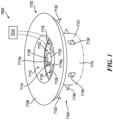
Figure 1 is a schematic view of an exemplary embodiment of a surgical sealing device; -
Figure 2 is a cross-sectional view of the surgical sealing device ofFigure 1 ; -
Figure 3 is a cross-sectional view of another exemplary embodiment of a surgical sealing device; -
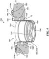
Figure 4 is a cross-sectional view of another exemplary embodiment of a surgical sealing device, showing the device inserted into a natural body orifice; -
Figure 5 is an exemplary image of a colon; -
Figure 6 is a schematic view of an exemplary embodiment of a surgical system having first and second multi-port devices; -
Figure 7 is a schematic view of the surgical system ofFigure 6 , showing the first and second multi-port devices partially inserted within an abdominal cavity; -
Figure 8 is a schematic view of an exemplary embodiment of a surgical sealing system having a sealing device with ports extending therethrough; -
Figure 9 is a top view of the sealing device ofFigure 8 ; -
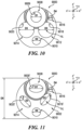
Figure 10 is a schematic view of the ports of the surgical sealing port ofFigure 8 ; -
Figure 11 is a schematic view of the altered ports of the surgical sealing port ofFigure 10 ; -
Figure 12 is the sealing device ofFigure 8 , showing an instrument inserted into one port of the sealing device; -
Figure 13 is a schematic view of an exemplary embodiment of a surgical sealing system having threaded restraints; -
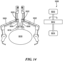
Figure 14 is a schematic of an exemplary embodiment of a surgical robotic system that includes electomechanical arms each having a surgical instrument mounted thereto, and being wirelessly coupled to a control system; -
Figure 15 is schematic view of an embodiment of a locking arm; and -
Figure 16 is a schematic view of one embodiment of a locking structure prior to exposure to external energy; and -
Figure 17 is the locking structure ofFigure 16 after exposure to external energy. - Certain exemplary embodiments will now be described to provide an overall understanding of the principles of the structure, function, manufacture, and use of the devices, systems, and methods disclosed herein. One or more examples of these embodiments are illustrated in the accompanying drawings. A person skilled in the art will understand that the devices, systems, and methods specifically described herein and illustrated in the accompanying drawings are non-limiting exemplary embodiments and that the scope of the present invention is defined solely by the claims. The features illustrated or described in connection with one exemplary embodiment may be combined with the features of other embodiments.
- Further, in the present disclosure, like-named components of the embodiments generally have similar features, and thus within a particular embodiment each feature of each like-named component is not necessarily fully elaborated upon. Additionally, to the extent that linear or circular dimensions are used in the description of the disclosed systems, devices, and methods, such dimensions are not intended to limit the types of shapes that can be used in conjunction with such systems, devices, and methods. A person skilled in the art will recognize that an equivalent to such linear and circular dimensions can easily be determined for any geometric shape. A person skilled in the art will appreciate that a dimension may not be a precise value but nevertheless be considered to be at about that value due to any number of factors such as manufacturing tolerances and sensitivity of measurement equipment. Sizes and shapes of the systems and devices, and the components thereof, can depend at least on the size and shape of components with which the systems and devices will be used.
- In certain embodiments, surgical sealing devices are provided that are configured to allow surgical access into a body cavity through a natural body orifice (e.g., a trachea, a rectum, and the like). In general, the present surgical sealing devices include a seal housing that is configured to be at least partially disposed within a natural body orifice and at least one retention element configured to affix the seal housing to the natural body orifice. Unlike conventional surgical sealing devices that are typically inserted into an incision, the present surgical sealing devices are designed to be inserted into a natural body orifice. As a result, the present surgical sealing devices provide a less traumatic and more direct access point to a natural body lumen or organ (e.g., for introduction and extraction of surgical instruments, fluid exchange, breathing apparatuses, smoke evacuation apparatuses, etc.) that would not otherwise be available through the use of conventional surgical sealing devices.
- In use, as discussed in more detail below, the surgical sealing devices disclosed herein can be used to provide access to a natural body lumen, such as a colon, through a natural body orifice associated therewith. That is, the seal housing can be at least partially positioned within a natural body orifice. Given the contractive nature of a natural body orifice, however, it can be difficult maintain the seal housing within the natural body office. As a result, the surgical sealing devices include at least one retention element (e.g., arranged on an exterior surface of the seal housing) that enables and maintains fixation of the seal housing to the natural body orifice during device use. The at least one retention element can be configured to be deployed inside or outside of the patient's body.
- The seal housing can be positioned and affixed to the natural body orifice in such a way in which a distal portion of the seal housing extends into the natural body orifice, and a proximal portion extends out of the natural body orifice and into the ambient environment (e.g., positioned adjacent to and in contact with an exterior surface of the patient's body, such as the patient's skin. Alternatively, the seal housing can be designed to be entirely positioned within the natural body orifice.
- Further, the seal housing generally includes one or more ports arranged within the seal housing to allow instruments to pass into the natural body lumen from the ambient environment through the natural body orifice. The one or more ports arranged through the seal housing can form pathway(s) into and through the natural body orifice. This can enable controlled fluid exchange through the natural body orifice, and consequently, into and/or out of the natural body lumen associated therewith, introduction and extraction of surgical instruments through the natural body orifice, and the like. As a result, the natural body lumen can be accessed without the need for an incision through the patient's skin.
-
Figure 1 andFigure 2 illustrate one embodiment of asurgical sealing device 7000 that is configured to provide access into a natural body lumen or organ (e.g., a lung, a stomach, a colon, or small intestines) through a natural body orifice (e.g., esophagus, rectum, and the like). Therefore, at least a portion of thesurgical sealing device 7000 is configured to be inserted into and stabilized within a natural body orifice. - The
sealing device 7000 includes aseal housing 7100 with ports extending therethrough and at least one retention element on theexterior surface 7101 of theseal housing 7100. While the at least one retention element can have a variety of configurations, in this illustrated embodiment, the at least one retention element includesfirst retention elements 7130 andsecond retention elements 7132. The first andsecond retention elements seal housing 7100 within a natural body orifice. - In use, the
surgical sealing device 7000 can be positioned within a natural body orifice, such as by deforming theseal housing 7100, or a portion thereof (e.g., the outer body member 7104) and inserting theseal housing 7100 in the natural body orifice. The insertion of the seal housing can be performed by hand or by using an insertion tool. The at least one retention element is releasably positioned to thereby affix the seal housing to the natural body orifice. In some embodiments, the at least one retention element can be deployed inside the natural body lumen, whereas in other embodiments, the at least one retention element can be deployed outside of the natural body lumen. The at least one retention member can be releasably positioned concurrently with or subsequently after the sealing housing is positioned at least partially within the natural body lumen. To withdraw thesurgical sealing device 7000 from the natural body orifice, a portion of the seal housing 7100 (e.g., the outer body member 7104) can be gripped with one or both hands (such as at opposite sides of the outer body member 7104) or by a removal instrument, or both, and theseal housing 7100 may be pulled proximally to withdraw theseal housing 7100 from natural body orifice. Prior to gripping the seal housing, the at least one retention element can be moved or otherwise disengaged from tissue defining the natural body orifice or tissue positioned proximate to the natural body orifice. - As shown in
Figure 1 andFigure 2 , the first andsecond retention elements exterior surface 7101 of theseal housing 7100. The first andsecond retention elements - In this illustrated embodiment, the first and
second retention elements seal housing 7100 to the natural body orifice. Further, theretention elements seal housing 7100 securely lodged within the natural body orifice. - In other embodiments, the at least one retention element can have a structural configuration that is configured to contact and engage the tissue surrounding or adjacent to the natural body orifice without penetration. That is, the at least one retention element can have a structural configuration that is configured to frictionally engage with the tissue so to prevent the seal housing from further movement within the natural body orifice during use. By way of example, in some embodiments, the at least one retention element can be in the form of an expandable element (e.g., inflatable balloons), as illustrated in
Figure 3 . In use, once the seal housing is inserted (e.g., partially or fully) within the natural body orifice, the expandable element(s) can be inflated, and when the seal housing is to be removed from the natural body orifice, the expandable element(s) can be deflated. - In some embodiments, when one or more retention elements are expandable elements, these retention elements can configured to be expanded within the natural body orifice (e.g., after at least a portion of the seal housing is inserted into the natural body orifice). In other embodiments one or more retention elements can be configured to be deployed outside of the natural body lumen (e.g., after at least a portion of the seal housing is inserted into the natural body orifice). Alternatively, in certain embodiments, at least one retention element can be configured to be deployed within the natural body orifice, and at least another one retention element can be configured to be deployed outside the natural body orifice. A person skilled in the art will appreciate that the deployable position of the retention elements depends at least upon the position of the retention elements relative to the
seal housing 7100 and the position of theseal housing 7100 relative to the natural body orifice when theseal housing 7100 is inserted therein. -
Figure 3 illustrates an exemplary embodiment of asurgical sealing device 7400 that includes a sealinghousing 7402 and tworetention elements retention elements Figure 3 ). Aside from the differences described in detail below, sealingdevice 7400 can be similar to sealing device 7000 (Figure 1 andFigure 2 ) and therefore common features are not described in detail herein. As shown, thefirst retention element 7404 is positioned at a first end 7202a of theseal housing 7402 and thesecond retention element 7406 is positioned at a second end 7202b of theseal housing 7402. Further, when both the first andsecond retention elements Figure 3 , they are configured to contact and frictionally engage an internal surface of the natural body orifice. In embodiments where only a portion of thesurgical sealing device 7400 is positioned within the natural body orifice, thesecond end 7402b of theseal housing 7402 can be positioned outside the natural body orifice (e.g., outside of the body of the patient). In such embodiments, thesecond retention element 7406 can be configured to contact and frictionally engage the outer tissue surface surrounding or adjacent to the natural body orifice (e.g., an external surface of the natural body orifice). - Referring back to
Figure 1 andFigure 2 , theseal housing 7100 ofsurgical sealing device 7000 can have a variety of configurations. For example, in this illustrated embodiment, theseal housing 7100 has aninner body member 7102 and anouter body member 7104 that is positioned about theinner body member 7102. In other embodiments, the outer body member can designed so as to extend distally from one end of the inner body member. In certain embodiments, the outer body member can be omitted. - The
inner body member 7102 and theouter body member 7104 can each have a variety of configurations. In this illustrated embodiment, theinner body member 7102 has a generally cylindrical configuration. Theouter body member 7104 includes anannular flange 7106 with an elongatedcylindrical base 7110 extending therefrom. Further, thebase 7110 defines alumen 7112 extending therethrough. Thelumen 7112, as shown inFigure 1 andFigure 2 , at least partially houses theinner body member 7102. A person skilled in the art will appreciate that the inner body member and/or the outer body member, and/or portions thereof, can have other suitable shapes and sizes (e.g., oval, elliptical, ovoid, and any combination thereof) and therefore their configurations are not limited to what is shown in the figures. - The
inner body member 7102 and theouter body member 7104 can formed as a unitary structure, permanently coupled to each other, or releasably coupled to each other. For example, in some embodiments, theinner body member 7102 can be configured to be inserted into and/or removed from the lumen 7112 (e.g., while theouter body member 7104 is at least partially positioned within a natural body orifice). In certain embodiments, theouter body member 7104 can be configured to provide assistance in preventing theinner body member 7102 from be pushed through the sealing housing 7100 (e.g., and into the body of the patient), and to assist in removing theinner body member 7102 from theseal housing 7100. For example, during surgery, removal of theinner body member 7102 may be needed for removing damaged or diseased tissue through thelumen 7112 of theouter body member 7104. Further, in addition, or alternatively, theouter body member 7104 can be configured to help prevent theinner body member 7102 from being torn or otherwise damaged by surgical instrument(s) that is/are inserted therethrough (e.g., during surgery). - As further shown in
Figure 1 andFigure 2 , theinner body member 7102 includes ports that extend therethrough, and thus, through theseal housing 7100. While theinner body 7102 can include two or more ports, in this illustrated embodiment theinner body member 7102 includes three ports: afirst port 7114, asecond port 7116, athird port 7118. Eachport respective passageway seal housing 7100. Theports - In some embodiments, at least one port can be configured to form a seal (e.g., around an instrument inserted therethrough) and at least another one port can be configured to control the ingress and/or egress of fluid (e.g., liquid, gas, or a combination thereof) between an interior volume of the natural body orifice and an ambient environment. In certain embodiments, at least one port can be configured to seal and control ingress and/or egress of fluid. For purposes of this discussion, the first and
second ports third port 7118 is configured to control the fluid ingress and egress. A person skilled in the art that any of these ports can configured to control fluid ingress and/or egress (e.g., air into and/or out of the natural body orifice, e.g., for breathing or insufflation) and/or to form a seal (e.g., around an instrument inserted therethrough and/or when an instrument is absent, for preventing loss of fluid therethrough). - In some embodiments, sealing element(s) can be positioned within the first port and/or second port to form a seal therein. In some embodiments, the sealing element(s) can be in the form of a thin membrane formed of a flexible material which can be punctured or otherwise pierced by a surgical instrument. In addition, or alternatively, zero closure sealing elements such as a duck bill seal or other suitable seals for sealing in the absence of instrument can be used in association with the ports. The sealing elements can be positioned at any suitable location within the port.
- As shown in
Figure 1 andFigure 2 , afirst sealing element 7126 is positioned within thepassageway 7120 of thefirst port 7114 and asecond sealing element 7128 is positioned within the passageway of thesecond port 7116. In some embodiments, the first andsecond sealing elements second sealing elements second sealing elements first sealing element 7126 is positioned proximate to theproximal end 7114p (e.g., the end closest to the ambient environment during use) of the first port and thesecond sealing element 7128 is positioned proximate to theproximal end 7116p (e.g., the end closest to the ambient environment during use) of thesecond sealing port 7116. In other embodiments, the first sealing element, the second sealing element, or both, can be positioned at a distal end of the second port and the third port, respectively. - In some embodiments, the
first sealing element 7126, thesecond sealing element 7128, or both can be further configured to limit the direction of airflow while also providing sealed access for the surgical instruments through theseal housing 7100. This can prevent contamination from aerosolized viruses or contagions during treatment due to the advancement and extraction of surgical instruments through thefirst port 7114 and/or thesecond port 7116. Additionally, the first sealing element, the second sealing element, or both can be a one-way valve to allow exhaust to be vented to a fluid trap and particulate filter to control the expiration of contagions. In another exemplary embodiment, thesurgical sealing device 7000 can have a small higher pressure inlet and a larger exhaust port for controlling exhaust gases being expelled from the natural body lumen. - In addition to the insertion and extraction of one or more surgical instruments through the first and
second ports third port 7118 of thesurgical sealing device 7000. That is, in this illustrated embodiment, thethird port 7118 is designed to allow the ingress and egress of fluid between an interior volume of the natural body orifice and an ambient environment. - In certain embodiments, as shown in
Figure 1 , thethird port 7118 can be operatively connected to avalve 7210. Thevalve 7210 can be configured to monitor a parameter that can be used to control a fluid transfer rate through thethird port 7118. The monitored parameter can be a fluid transfer pressure, a fluid transfer volume, and/or a direction of the fluid transfer therethrough. For example, the valve can include a sensor that is configured to sense the pressure, volume, or flow direction of the fluid as it passes through the valve, and transmit the sensed data to a controller (not shown). If at any time during use, the controller determines that the sensed data is outside of a predetermined range(s), the controller can alter the valve position (e.g., partially close or open the valve relative to its current position) to change the pressure, volume, or flow direction of the fluid therethrough, and consequently, through thethird port 7118. Non-limiting examples of suitable sensors include pressure, temperature, and flow sensors. In other embodiments, a controller can be omitted, and the valve can be structurally configured to control the fluid flow therethrough by itself, and therefore alter the pressure, volume, or flow direction, if needed. - During an electrosurgical procedure, energy devices can delivery mechanical and/or electrical energy to target tissue in order to treat the tissue (e.g., to cut the tissue, cauterize blood vessels and/or coagulate the tissue within and/or near the targeted tissue). The cutting, cauterization, and/or coagulation of tissue can result in fluids and/or particulates being released into the air. Such fluids and/or particulates emitted during a surgical procedure can constitute smoke, for example, which can comprise carbon particles and/or other particles suspended in air. As a result, electrosurgical systems typically employ a surgical evacuation system that captures the resultant smoke from a surgical procedure, and directs the captured smoke through a filter and a smoke exhaust port away from the clinician(s) and/or from the patient(s).
- For example, surgical procedures on a lung can require inhalation and expulsion of breathable air and exhaustion of smoke that is generated during the procedure. In such instances, cooperative control of the smoke evaluation and breathing apparatus can be helpful. As such, the surgical sealing devices disclosed herein can be configured to enable simultaneous trans-seal system use. That is, the present surgical sealing devices can be configured to provide smoke evacuation control of a fluid exchange system that allows cooperative flow of fluid such that, during surgery, the body can continue to receive the intended flow of fluid (e.g., breathable air) while also allowing extraction of a portion of the fluid through a different path to direct the smoke extraction from the patient.
- In some embodiments, the smoke exhaust port can be its own separate port within the seal housing or it can be combined with another port of the seal housing (e.g., a port that is connected to a breathing apparatus that inflates and deflates the lung with breathable air and/or configured for insertion and extraction of surgical instruments), or the smoke evacuator passage can be a working passage of a flexible endoscope inserted through a port of the seal housing for controlling the ingress and egress of lung gasses as needed for breathing and smoke evacuation. If the smoke evacuation is activated when the body is breathing, an additional airflow inlet can be configured as a port of the seal housing to offset the smoke evacuation air flow, resulting in enough air for lung inflation while cooperatively extracting smoke and air form the lung. In some embodiments, the smoke evacuation system can be configured to pass the smoke to an externally connected smoke evacuator pump and filters, while in other embodiments, the smoke evacuation system can be arranged to use the same filters as a primary breathing exhaust system coupled to the breathing passage port of the seal housing. Exemplary smoke evacuator systems suitable for use with the present disclosure are described, for example, in
U.S. Patent No. 11,051,876 entitled "Surgical Evacuation Flow Paths" issued July 6, 2021 U.S. Patent Publication No. 2019/0201088 entitled "Surgical Evacuation System With A Communication Circuit For Communication Between A Filter And A Smoke Evacuation Device" published July 4, 2019 , andU.S. Patent Publication No. 2019/0204201 entitled "Adjustments Based On Airborne Particle Properties" published July 4, 2019 . -
Figure 4 illustrates another embodiment of asurgical sealing device 7300. Aside from the differences described in detail below, thesurgical sealing device 7300 can be similar to surgical sealing device 7000 (Figure 1 andFigure 2 ) and therefore common features are not described in detail herein. Thesurgical sealing device 7300 is shown at least partially inserted within anatural body orifice 10 formed bytissue 12. Thesurgical sealing device 7300 includes aseal housing 7301 having aninner body member 7302 and an outer body member 7304 that is positioned about theinner body member 7302. Theinner body member 7302 has threeports ports smaller ports 7308, 7310 (e.g., to receive relatively smaller devices, such as graspers, clip appliers, or the like). - Further, the
seal housing 7301 includesfirst retention elements 7312 andsecond retention elements 7314. As shown, thefirst retention elements 7312 extend outward from the elongated cylindrical base 7316 of the outer body member 7304 and thesecond retention elements 7314 extend from abottom surface 7318a of the annular flange 7318 of the outer body member 7304. Thefirst retention elements 7312 engage with aninternal surface 7320 of thenatural body orifice 10 and penetrate portions of thetissue 12 that define suchinternal surface 7320. Since thesurgical sealing device 7300 is only partially inserted into thenatural body orifice 10, the annular flange 7318 of theseal housing 7300 is positioned outside of thenatural body orifice 10. As a result, thesecond retention elements 7314 engage anouter tissue surface 7322 surrounding thenatural body orifice 10 and penetrate portions of thetissue 12 that define such outer surface 7322 (e.g., external surface of the natural body lumen). This penetration by both the first andsecond retention elements tissue 12 affix theseal housing 7301 to thenatural body orifice 10 so as to allow one or more surgical instruments to be inserted and extracted through thenatural body orifice 10 and/or fluid transfer to occur through thenatural body orifice 10. - In some embodiments, the surgical sealing device can include wound protectors for use with natural body orifices that enable introduction and extraction of instruments while limiting instrument to tissue interaction. This limiting of interaction between the tissue and instruments can provide reduced friction between the body wall and the insertion forces of the instruments. The arrangement can minimize damage to the surrounding tissue during manipulation or advancing or retracting of the instruments through the sealing device.
- In some embodiments, the seal housing of the surgical sealing device can be configured as a mechanical fixation point for a flexible scope and/or instruments passing through the seal housing. The seal housing can be arranged such that a fixation point is formed by the seal housing being secured within the natural body orifice, which provides the flexible scope and/or instruments passing through the seal housing a resistive fixation point from which to resist internally generated forces, motions and actions from the instruments manipulating tissue within the body. The fixation point for the instruments would prevent inappropriate loads on the patient during movement of the instruments within the sealing device. The fixation point could be outside of the body and prevent excessive torque from being applied to the body by the instruments through the sealing device.
- While the
seal housings Figure 1 andFigure 2 ,Figure 3 , andFigure 4 are illustrated as a separate device which to be inserted into a natural body orifice and allows instruments to be inserted therethrough and into a natural body lumen, in other embodiments a seal housing can be arranged on an instrument, such as a gastroscopic bougie, as the instrument is inserted into a natural body orifice. A gastroscopic bougie is commonly understood to be a thin cylinder of rubber, plastic, metal or another material that a medical practitioner inserts into or through a body passageway, such as the esophagus, to diagnose or treat a condition. A bougie may be used to widen a passageway, guide another instrument into a passageway, or dislodge an object. The gastroscopic bougie can include a seal housing having retention elements which are configured to be deployed in the esophagus prior to the stomach. This arrangement would allow laparoscopic access to the stomach while the abdominal cavity is insufflated for procedures such as a tumor resection within the stomach. By arranging the seal housing in the esophagus, the laparoscopic insufflation is prevented from escaping endoluminally, while also allowing bougie to manipulate the stomach and tumor through four-wire control. - In certain embodiments, surgical systems that enable control of surgical instrument interactions between separate port devices are provided. In general, these systems have two or more port devices (e.g., multi-port devices) that include respective housings that are each configured to allow instruments from respective sets of instruments to be inserted therethrough. The two or more port devices are each designed to provide individualized resistive forces to respective inserted instruments and to allow the inserted instruments to work cooperatively together (e.g., for at least one surgical step of a surgical procedure or at one or more surgical sites, etc.). The two or more port devices are interconnected to each other (e.g., electrically or mechanically) to create an interrelationship between the inserted instruments. This interrelationship enables these instruments to work in combination (e.g., move concurrently or sequentially in the same or different direction relative to each other or in groups) to provide the force(s), retraction, access angle(s), and the like to carry out at least one surgical step (e.g., to provide the intended medial therapy). As a result, these cooperative movements between at least a portion of the inserted instruments can provide a more collaborative surgical environment within the same port or among different ports that can increase precision and help prevent collisions (e.g., of surgical instruments and/or robotic arms).
- A person skilled in the art will understand that the phrase "work cooperatively together" as used herein refers to coordinated movement between two or more inserted instruments in the same port, in separate ports, or a combination thereof based on a location, an orientation, or a motion of at least one inserted instrument of the two or more inserted instruments. Similarly, a person skilled in the art will understand that the coordinated movement between the two or more inserted instruments can occur in the same direction at the same time, in the same direction at different times, opposing directions at the same time, opposing directions at different times, in the same plane at the same time, in the same plane at different times, in two separate planes at the same time, in two different planes at different times, or any combination thereof.
- Each port device is configured to be at least partially disposed with a body. For example, a first port device can be partially inserted into a body (e.g., through a natural orifice or an opening made by an incision) and a second port device can be partially inserted into the (e.g., through a natural orifice or an opening made by an incision). The first and second port devices can be partially inserted within the same physiological space or different physiological spaces. In some embodiments, the first port device can bridge the ambient environment with a first physiological space inside the body (e.g., thoracic cavity or abdomen cavity and the second port device can bridge the ambient environment and a second physiological space that is not directly connected to the first physiological space (e.g., through a natural orifice to inside the colon, esophagus or other physiologic tract). In other embodiments, the first and second physiological spaces are directly connected to each other. For example, in one embodiment, the first port device can be partially inserted into a first abdominal quadrant and the second port device can be partially inserted into a second abdominal quadrant that is different than the first abdominal quadrant.
- The housing of each port device can be positioned and affixed to body in such a way in which a distal portion of the housing extends into the body (e.g., a physiological space), and a proximal portion extends out of the body and into the ambient environment (e.g., positioned adjacent to and in contact with an exterior surface of the patient's body, such as the patient's skin). Alternatively, the housing can be designed to be entirely positioned within the body.
- Further, the housing of each port device generally includes ports arranged within the housing that allow instruments to be inserted therethrough into the body (e.g., a physiological space, such as a one or more cavities within the body) from the ambient environment through a natural body orifice or an opening made by an incision. The ports arranged through the housing can form pathway(s) into and through the body.
- In some embodiments, at least one port of at least one port device can be configured to form a seal around an inserted instrument. In one embodiment, at least one port of the first port device can be configured to form a seal around a respective inserted instrument of a first set of instruments. Alternatively, or in addition, at least one port of the second port device can be configured to form a seal around a respective inserted instrument of a second set of instruments.
- In certain embodiments, sealing element(s) can be positioned within the at least one port to form a seal therein. The sealing element(s) can have a variety of configurations. In some embodiments, the sealing element(s) can be in the form of a thin membrane formed of a flexible material which can be punctured or otherwise pierced by a surgical instrument. Alternatively, or in addition, zero closure sealing elements such as a duck bill seal or other suitable seals for sealing in the absence of instrument can be used in association with the at least one port. The sealing elements can be positioned at any suitable location within the at least one port.
- In some embodiments, when first and second instruments are inserted into respective ports of the first port device, the first port device can be configured to allow the first instrument to move within a first range of motion relative to the first port device and to allow the second instrument to move within a second range of motion relative to the first port device that is at least partially overlaps with the first range of motion. Alternatively, or in addition, when first and second instruments are inserted into respective ports of the second port device, the second port device can be configured to allow the first instrument to move within a first range of motion relative to the second port device and to allow the second instrument to move within a second range of motion relative to the second port device that at least partially overlaps with the first range of motion.
- In use, as discussed in more detail below, the respective port device provides resistive inter-device forces to respective inserted instruments (e.g., to prevent unintended contact between inserted instruments). That is, during movement of an inserted instrument, the port device can restrain movement of the inserted instrument relative to other inserted instruments in the same port device, in at least one other port device, or a combination thereof. The port device(s) of the surgical system are configured to interact at least one inserted instrument in such a way that limits one or more instrument motions. This limitation can be based on, for example, at least one of a location, orientation, and a motion of at least one other instrument of the same set of inserted instruments, at least one other instrument of a different set of inserted instruments, or both.
- The location, orientation, motion, or any combination thereof, of an inserted instrument can be determined, for example, by using one or more tracking device(s) or a tracking system. In some embodiments, the system can include a tracking device that can be associated with one of the first port device or the second port device. The tracking device can be configured in a variety of ways. In certain embodiments, the tracking device can be configured to transmit a signal indicative of a location of the first port device relative to the second port device. Alternatively, or in addition, the tracking device can be configured to transmit a signal indicative of at least one of a location, an orientation, and a motion of at least one inserted instrument in the first port device relative to the second port device. Alternatively, or in addition, the tracking device can be configured to transmit a signal indicative of at least one of a location, an orientation, and a motion of at least one inserted instrument in the second port device relative to the first port device.
- The transmitted signal(s) from the tracking device can be received by a controller. In general, depending on the data of the received signal, the controller can determine at least one or more of the following: a relative location of the first port device and the second port device, at least one of the location, the orientation, and the motion of at least one inserted instrument in the first port device relative to the second port device, or at least one of the location, the orientation, and the motion of the at least one inserted instrument of in the second port device relative to the first port device based on the respective transmitted signal. This information is used as guidance for movement of the inserted instruments individually, as a single group, or as multiple groups. This guidance in combination with the resistive forces applied by the respective port devices can control instrument interaction between the inserted instruments such that the inserted instruments can work cooperatively together at one or more surgical sites and/or to perform at least one surgical step of a surgical procedure.
- An exemplary surgical system can include a variety of features as described herein and illustrated in the drawings. However, a person skilled in the art will appreciate that the surgical systems can include only some of these features and/or it can include a variety of other features known in the art. The surgical systems described herein are merely intended to represent certain exemplary embodiments. Moreover, while the surgical systems are shown and described in connection with a colon, a person skilled in the art will appreciate that these surgical systems can be used in connection with any other suitable natural body lumens or organs.
- Surgery is often the primary treatment for early-stage colon cancers. The type of surgery used depends on the stage (extent) of the cancer, its location in the colon, and the goal of the surgery. Some early colon cancers (stage 0 and some early stage I tumors) and most polyps can be removed during a colonoscopy. However, if the cancer has progressed, a local excision or colectomy, a surgical procedure that removes all or part of the colon, may be required. In certain instances, nearby lymph nodes are also removed. A hemicolectomy, or partial colectomy, can be performed if only part of the colon is removed. In a segmental resection of the colon the surgeon removes the diseased part of the colon along with a small segment of non-diseased colon on either side. Usually, about one-fourth to one-third of the colon is removed, depending on the size and location of the cancer. Major resections of the colon are illustrated in
Figure 5 , in which (i) A-B is a right hemicolectomy, A-C is an extended right hemicolectomy, B-C is a transverse colectomy, C-E is a left hemicolectomy, D-E is a sigmoid colectomy, D-F is an anterior resection, D-G is a (ultra) low anterior resection, D-H is an abdomino-perineal resection, A-D is a subtotal colectomy, A-E is a total colectomy, and A-H is a total procto-colectomy. Once the resection is complete, the remaining intact sections of colon are then reattached. - During a laparoscopic-assisted colectomy procedure, it is often difficult to obtain an adequate operative field. Often times, dissections are made deep in the pelvis which makes it difficult to obtain adequate visualization of the area. As a result, the lower rectum must be lifted and rotated to gain access to the veins and arteries around both sides of the rectum during mobilization. During manipulation of the lower rectum, bunching of tissue and/or overstretching of tissue can occur. Additionally, a tumor within the rectum can cause adhesions in the surrounding pelvis, and as a result, this can require freeing the rectal stump and mobilizing the mesentery and blood supply before transection and removal of the tumor.
- After a colectomy, the remaining healthy portions of the colon must be reattached to one another to create a path for waste to leave the body. However, when using laparoscopic instruments to perform the colectomy, one single entry port device may not have a large enough range of motion to move the one end of the colon to connecting portion. As such, a second entry port device is therefore needed to laparoscopically insert instruments to help mobilize the colon and/or purchase the one end of the colon from a laparoscopic instrument of the first entry port device and move the one end to the connecting portion. The multiple port devices having multiple instrument inserted therethrough to carry out at least one surgical step or site can increase the chance of surgical errors and collisions between surgical instruments or robotic arms.
- The present surgical systems include multiple port devices (e.g., multi-port devices) that interconnect multiple groups of surgical instruments that can move together while also providing individualized resistive inter-device forces and motions to the surgical instruments. For example, a first port device can be configured to receive a first set of instruments (e.g., two or more instruments) and a second port device can be configured to receive a second set of instruments (e.g., two or more instruments), and when at least one instrument from the first set and from the second set are inserted into the first and second port devices, respectively, these instruments can move together as a single group. Alternatively, or in addition, at least one inserted instrument of the first set can move with at least one instrument of the second set, or vice versa.
-
Figure 6 illustrates an exemplary embodiment according to the invention of asurgical system 8000 that is configured to for laparoscopic and/or endoscopic access into a body through two or more interconnected multi-port devices.Figure 7 schematically illustrates thesurgical system 8000 being used in a surgical resection procedure on acolon 10. For purposes of simplicity, certain components of thesurgical system 8000 are not illustrated. - As shown, the
surgical system 8000 includes a firstmulti-port device 8100 and a secondmulti-port device 8200, in which eachmulti-port device - The first
multi-port device 8100 can have a variety of configurations. For example, in some embodiments, as shown inFigure 6 andFigure 7 , the firstmulti-port device 8100 includes afirst housing 8101 with afirst port 8102 and asecond port 8104 defined therein. The first andsecond ports Figure 7 ) can be inserted into thefirst port 8102 and a second instrument 8108 (show in more detail inFigure 7 ) can be inserted into thesecond port 8104. The first andsecond instruments - In use, the first
multi-port device 8100 interacts with thefirst instrument 8106, thesecond instrument 8108, or both. The firstmulti-port device 8100 can be configured to interact with thefirst instrument 8106 and thesecond instrument 8108 concurrently, separately, or both. By way of example, the firstmulti-port device 8100 interacts with thefirst instrument 8106, and during the interaction, the firstmulti-port device 8100 applies resistive forces to thefirst instrument 8106. These resistive forces limit one or more motions of thefirst instrument 8106 based on at least one of a location, orientation, and a motion of thesecond instrument 8108. A person skilled in the art will understand that the firstmulti-port device 8100 is configured to have a similar interaction with thesecond instrument 8108. - The
first housing 8101 can be formed of one or more suitable material(s). In some embodiments, a first portion of the first housing can be formed of at least one first material and a second portion of the first housing can be formed of at least one second material. In such embodiments, the first portion can be more flexible than the second portion or vice versa. In other embodiments, the first housing is uniformly formed of one or more suitable material(s). A person skilled in the art will understand that the amount and type of resistive forces the first multi-port device applies to any inserted instrument will depend at least upon the material(s) and structural configuration of the first housing and the amount of force and the direction of force applied to the respective port by the inserted instrument. - The first and
second ports first sealing element 8103 and asecond sealing element 8105 can be positioned within thefirst port 8102 and thesecond port 8104, respectively. The sealingelements - In use, the first and
second sealing elements second instruments second instruments multi-port device 8100. In certain embodiments, one or more of the inserted instruments of the firstmulti-port device 8100 can pivotally move relative to thefirst housing 8101. - The second
multi-port device 8200 can have a variety of configurations. For example, in some embodiments, as shown inFigure 6 , the secondmulti-port device 8200 includes asecond housing 8201 with athird port 8202 and afourth port 8204 defined therein. The third andfourth ports Figure 7 ) can be inserted into thethird port 8202 and a fourth instrument 8208 (shown in more detail inFigure 7 ) can be inserted into thefourth port 8204. The third andfourth instruments - In use, the second
multi-port device 8200 interacts with thethird instrument 8206, thefourth instrument 8208, or both. The secondmulti-port device 8200 can be configured to interact with thethird instrument 8206 and thefourth instrument 8208 concurrently, separately, or both. By way of example, the secondmulti-port device 8200 can interact with thethird instrument 8206, and during this interaction, the secondmulti-port device 8200 applies resistive forces to thethird instrument 8206. These resistive forces limit one or more motions of thethird instrument 8206 based on at least one of a location, orientation, and a motion of thefourth instrument 8208. A person skilled in the art will understand that the secondmulti-port device 8200 is configured to have a similar interaction with thefourth instrument 8208. - The
second housing 8201 can be formed of one or more suitable material(s). In some embodiments, a first portion of the second housing can be formed of at least one first material and a second portion of the second housing can be formed of at least one second material. In such embodiments, the first portion can be more flexible than the second portion or vice versa. In other embodiments, the second housing is uniformly formed of one or more suitable material(s). A person skilled in the art will understand that the amount and type of resistive forces the second multi-port device applies to any inserted instrument will depend at least upon the material(s) and structural configuration of the second housing and the amount of force and the direction of force applied to the respective port by the inserted instrument. - The third and
fourth ports third sealing element 8203 and afourth sealing element 8205 can be positioned within thethird port 8202 and thefourth port 8204, respectively. The third andfourth sealing elements - In use, the third and
fourth sealing elements fourth instruments fourth instruments multi-port device 8200. In certain embodiments, one or more of the inserted instruments of the secondmulti-port device 8200 can pivotally move relative to thesecond housing 8201. - Further, the first
multi-port device 8100 and/or the secondmulti-port device 8200 can incorporate various tracking mechanisms, such as electromagnetic (EM) tracked tips, fiber bragg grating, various sensors, etc., to assist in tracking orientation, location, and movement of the instruments. The firstmulti-port device 8100 and the second multi-port device include afirst tracking device 8110 and asecond tracking device 8210, respectively. Each of the first andsecond tracking devices multi-port devices multi-port devices multi-port devices multi-port devices - In use, with respect to the
first tracking device 8110, as the third andfourth instruments first tracking device 8110 is configured to transmit afirst signal 8112 to acontroller 8002 that includes sensed data associated with thethird instrument 8206, thefourth instrument 8208, or the second set of instruments. That is, thefirst tracking device 8110 is configured to sense, or otherwise track, thethird instrument 8206, thefourth instrument 8208, or both (e.g., the second set of instruments), as such instrument(s) is/are inserted into and moved in the body with or relative to the secondmulti-port device 8200. Alternatively, or in addition, thefirst signal 8112 or an additional signal can include sensed data associated with the secondmulti-port device 8200. Thefirst tracking device 8110 is also configured to transmit asecond signal 8114 to thecontroller 8002 that includes sensed data associated with the first set of instruments and/or the firstmulti-port device 8100 itself. - Once the first and second transmitted
signals controller 8002, thecontroller 8002, based on these signals, can calculate location, position, or motion of thethird instrument 8206, thefourth instrument 8208, or both, relative to the first set of instruments and/or the firstmulti-port device 8100 itself. This creates one or more interrelationships between the first and second sets of instruments, and as a result, at least a portion of the first and second sets of instruments can work cooperatively together at one or more surgical sites and/or to carry out at least one surgical step of a surgical procedure. As shown inFigure 7 , and as described in more detail below, thefirst instrument 8106 and thethird instrument 8206 are working cooperatively together to handoff thefree end 15 of thecolon 10, and thesecond instrument 8108 and thefourth instrument 8208 are shown working cooperatively together to purchase the same area of thecolon 10. - Similarly, with respect to the
second tracking device 8210, in use, as the first andsecond instruments second tracking device 8210 is configured to transmit athird signal 8212 to thecontroller 8002 that includes sensed data associated with thefirst instrument 8106, thesecond instrument 8108, or the first set of instruments. That is, thesecond tracking device 8210 is configured to sense, or otherwise track, thefirst instrument 8106, thesecond instrument 8108, or both (e.g., the first set of instruments), as such instrument(s) is/are inserted into and moved within the body with or relative to the firstmulti-port device 8100. Alternatively, or in addition, thethird signal 8212 or an additional signal can include sensed data associated with the firstmulti-port device 8100. Thesecond tracking device 8210 is also configured to transmit afourth signal 8214 to thecontroller 8002 that includes sensed data associated with the second set of instruments and/or the secondmulti-port device 8200 itself. - Once the third and fourth transmitted
signals controller 8002, thecontroller 8002, based on these signals, can calculate location, position, or motion of thefirst instrument 8106, thesecond instrument 8108, or both, relative to the second set of instruments and/or the secondmulti-port device 8200 itself. This also creates one or more additional interrelationships between the first and second sets of instruments, and as a result, at least a portion of the first and second sets of instruments can work cooperatively together at one or more surgical sites and/or to carry out at least one surgical step of a surgical procedure. - The tracking mechanism of the first and
second tracking devices first tracking device 8110 can be configured to use magnetic sensing to detect a location, an orientation, or a motion of thethird instrument 8206, thefourth instrument 8208, or both relative to the firstmulti-port device 8100 and/or to determine a location of the secondmulti-port device 8200 relative to the firstmulti-port device 8100. In such instances, thethird instrument 8206, thefourth instrument 8208, or both and/or the secondmulti-port device 8200 includes a respective magnetic fiducial marker (not shown) that is configured to emit a respective magnetic field that can be detected by thefirst tracking device 8110. Alternatively, or in addition, thesecond tracking device 8210 can be configured to use a similar magnetic sensing mechanism to detect a location, an orientation, or a motion of at least one of the first andsecond instruments multi-port device 8200 and/or to determine a location of the firstmulti-port device 8100 relative to the secondmulti-port device 8200. In some embodiment, a magnetic tracking system is configured to output a defined directional field relative to the magnet, its orientation, and near-by metallic systems. When the magnet is a permanent magnet, the field is of a predefined intensity, size, and orientation. Since the field is vector directional, a magnetic sensor within the directional field is configured to sense from the intensity, direction of the magnet vectors, and change of those measures over time where the sensor is within the directional field and orientation of the sensor with respect to the magnet. When the magnet is an electro-magnet, the intensity and field direction can be alternated and changed as directed, which mitigates metal impacts on the field and interferences as well as increase accuracy. "DESIGN OF A MAGNETIC FIELD-BASED MULTI DEGREE-OF-FREEDOM ORIENTATION SENSOR USING THE DISTRBUTED-MULTIPLE-POLE MODEL" from Proceedings of IMECE2007 2007 ASME International Mechanical Engineering Congress and Exposition November 11-15, 2007, Seattle, Washington, USA illustrates and describes multi-degree freedom magnetic field tracking. - For another example, the
first tracking device 8110 can be configured to use common anatomic landmarks to detect a location, an orientation, or a motion of thethird instrument 8206, thefourth instrument 8208, or both relative to the firstmulti-port device 8100 and/or a location of the secondmulti-port device 8200 relative to the firstmulti-port device 8100. Alternatively, or in addition, thesecond tracking device 8210 can be configured to use common anatomic landmarks to detect a location, an orientation, or a motion of at least one of the first andsecond instruments multi-port device 8100 relative to the secondmulti-port device 8200. In some embodiments, the use of physiologic landmarks, and the distances and focal aspects of these landmarks with respect to an imaging system enable the imaging system to use the same imaging and distance measurements to determine the location and orientation of the instruments with respect to the anatomic location. These "reference" points would enable the system to using imaging & preoperative imaging to scale the measures allowing them to more accurately correct for focus or depth measures of the system. In certain embodiments, 3D imaging systems and/or Lidar imaging systems can both be used to enhance or replace the optical measurements with respect to the surgical sites. - For yet another example, a structured light scan can be used to create a 3D map. Electromagnetic tracking of the first
multi-port device 8100, the secondmulti-port device 8200 and theinstruments multi-port device 8100 and the first andsecond instruments multi-port device 8200 and third andfourth instruments colon 10 between the quadrants. Alternatively, or in addition, a line as registered in space can be communicated to the secondmulti-port device 8200 and the third andfourth instruments colon 10 between the quadrants. - Alternatively, for yet another example, the physical mechanical linkage angles between robotic arms holding the surgical instruments and their predefined lengths can be used to enhance a visual system's calculation of depth and focal distance between surgical instruments and a surgical site. By using the linkage angles and predefined length, the system can achieve triangulation of the instruments within a patient in order to "calibrate" or compensate for optical losses by the imaging system.
- For still another example, the
first tracking device 8110 can be an optical sensor that can be configured to detect a fiducial marker on the third instrument, the fourth instrument, and/or the second multi-port device. Alternatively, or in addition, the second tracking device can be an optical sensor that is configured to detect a fiducial marker on the first instrument, the second instrument, and/or the first multi-port device. Any number of multi-ports and/or surgical instruments can be tracked in this way during performance of a surgical procedure. - In some embodiments, controlling cooperative surgical instrument interactions includes using smart device location cooperatively with scope tracking. In general, a non-magnetic sensing system can be used for 3D tracking to provide X, Y, Z coordinates using a single receiver and at least one emitter. A time-of-flight distance sensor system, discussed above, may thus be used.
- For example, the non-magnetic sensing system can include ultrasonic sensor technology and radiofrequency (RF) sensor technology. A time of flight system can include an emitter and a receiver. To facilitate controlling cooperative surgical imaging interactions, the emitter includes an ultrasonic sensor (ultrasonic beacon) configured to transmit ultrasonic pulses, and the receiver includes an RF receiver configured to transmit an RF signal that commands the emitter to begin transmitting the ultrasonic pulses. The ultrasonic pulses are reflected back by object(s) within their range. The RF receiver is configured to record the ultrasonic pulses and to, based on the recorded ultrasonic pulses, calculate 3D coordinates (X, Y, Z) of the emitter. The sound propagation time of the ultrasonic pulses allows the RF receiver to calculate the 3D coordinates and to calculate distance to objects.
-
Figure 7 illustrates a schematic view of thesurgical system 8000 being used during a colon resection procedure. As explained above, thefirst tracking device 8110 of the firstmulti-port device 8100 can track thethird instrument 8206, thefourth instrument 8208, or both, and thesecond tracking device 8210 of the secondmulti-port device 8200 can track the location offirst instrument 8106, thesecond instrument 8108, or both, while the instruments are inserted into their respective port devices and arranged within the body. Further, the first andsecond instruments second graspers fourth instruments fourth graspers colon 10 and the mobilizedsection 12 thereof and help reattach the mobilizedsection 12 to therectum 14. - As shown in
Figure 7 , the first andsecond instruments multi-port device 8100 are arranged in the upper left quadrant of the abdominal cavity to mobilize the transverse and descendingcolon 10. The third andfourth instruments multi-port device 8200 are arranged in the lower left quadrant of the abdominal cavity to mobilize and create an incision along line IL to remove a tumor in the descending colon or sigmoid. Each set of instruments is accessing the abdominal cavity together through respectivemulti-port devices second instruments fourth instruments - Due to the location of the first and second
multi-port devices instruments section 12 of thecolon 10 transiting from the upper left quadrant to the lower right quadrant. Prior to and/or during the handoff, thefirst tracking device 8110 transmits the first andsecond signals controller 8002 and/or thesecond tracking device 8210 transmits the third andfourth signals controller 8002. The resulting interrelationship between the first and secondmulti-port devices 8100, 8200 (e.g., by way of the first and/or second tracking devices) enables triangulation and opposed motion of theinstruments free end 15 toward the rectum for attachment. More specifically, as shown inFigure 7 , thesecond instrument 8108 and thefourth instrument 8208 are purchasing the same area of thecolon 10, and thethird instrument 8206 is ready to grasp thefree end 15 of thecolon 10 from thefirst instrument 8106 to move thefree end 15 towards therectum 14. - Any one or more of the exemplary surgical systems, port devices and related methods described herein, and variations thereof, can be implemented in conventional surgical procedures conducted by a medical professional as well as in robotic-assisted surgical procedures. Various teachings herein may be readily incorporated into a robotic surgical system such as one or more of the DAVINCI™ systems by Intuitive Surgical, Inc., of Sunnyvale, Calif., including their SP™ surgical system. Exemplary robotic surgical systems and related features, which may be combined with any one or more of the exemplary surgical access devices and methods disclosed herein, are disclosed in the following:
U.S. Pat. No. 8,068,649, entitled "Method and Apparatus for Transforming Coordinate Systems in a Telemanipulation System," issued Nov. 29, 2011 ;U.S. Pat. No. 8,517,933, entitled "Retraction of Tissue for Single Port Entry, Robotically Assisted Medical Procedures," issued Aug. 27, 2013 ;U.S. Pat. No. 8,545,515, entitled "Curved Cannula Surgical System," issued Oct. 1, 2013 ;U.S. Pat. No. 8,551,115, entitled "Curved Cannula Instrument," issued Oct. 8, 2013 ;U.S. Pat. No. 8,623,028, entitled "Surgical Port Feature," issued Jan. 7, 2014 ;U.S. Pat. No. 8,771,180, entitled "Retraction of Tissue for Single Port Entry, Robotically Assisted Medical Procedures," issued Jul. 8, 2014 ;U.S. Pat. No. 8,888,789, entitled "Curved Cannula Surgical System Control," issued Nov. 18, 2014 ;U.S. Pat. No. 9,254,178, entitled "Curved Cannula Surgical System," issued Feb. 9, 2016 U.S. Pat. No. 9,283,050, entitled "Curved Cannula Surgical System," issued Mar. 15, 2016 U.S. Pat. No. 9,320,416, entitled "Surgical Instrument Control and Actuation," issued Apr. 26, 2016 U.S. Pat. No. 9,339,341, entitled "Direct Pull Surgical Gripper," issued May 17, 2016 U.S. Pat. No. 9,358,074, entitled "Multi-Port Surgical Robotic System Architecture," issued Jun. 7, 2016 U.S. Pat. No. 9,572,481, entitled "Medical System with Multiple Operating Modes for Steering a Medical Instrument Through Linked Body Passages," issued Feb. 21, 2017 U.S. Pat. No. 9,636,186, entitled "Multi-User Medical Robotic System for Collaboration or Training in Minimally Invasive Surgical Procedures," issued May 2, 2017 U.S. Pat. Pub. No. 2014/0066717, entitled "Surgical Port Feature," published Mar. 6, 2014 , issued asU.S. Pat. No. 10,245,069 on Apr. 2, 2019 U.S. Pat. Pub. No. 2017/0128041, entitled "Laparoscopic Ultrasound Robotic Surgical System," published May 11, 2017 ; andU.S. Pat. Pub. No. 2017/0128144, entitled "Laparoscopic Ultrasound Robotic Surgical System," published May 11, 2017 ; andU.S. Pat. Pub. No. 2017/0128145, entitled "Laparoscopic Ultrasound Robotic Surgical System," published May 11, 2017 . - In various surgical procedures, a surgeon may need to direct two or more surgical instruments into a body cavity simultaneously in order to gain access to and provide effective treatment to tissue. It is generally desirable, however, to minimize the number of surgical openings that need to be formed in the patient (e.g., in a patient's abdominal wall) to thereby mitigate tissue trauma, cosmetic damage, and post-operation recovery time for the patient. Accordingly, surgical sealing systems are provided that generally include a sealing device having a seal housing with ports for receiving surgical instruments.
- In general, the ports of the seal housing are designed to control or limit the motions of at least one instrument inserted through a respective port such that the instrument can stabilize another instrument inserted through a respective other port. Each of the ports can have a nominal size and shape and each can be configured to assume a selected size and/or shape that is different from the nominal size and/or shape. A person skilled in the art will understand that a nominal size and a nominal shape refer to a size and shape of a port without a force applied thereto. Similarly, a person skilled in the art will understand that a selected size and a selected shape of a port refers to a size and shape of a port when a force is applied to the port, such as by an instrument being inserted therethrough. It will be further understood by a person skilled in the art that the selected size and the selected shape will depend on the amount of force and the direction of force applied to the port, such as by the instrument.
- The selected size and/or shape of each port can be constrained by the size and shape of each of the other plurality of ports. As a result, forces applied to one port can affect the size and shape of the other ports. The force can be applied by an instrument that is disposed within one port of the plurality of ports. The force applied thereto is therefore effective to change the size and/or shape of the ports based on the movement, direction, and force of the instrument. Since the ability to alter to the nominal shape of any one port is therefore constrained or limited by the size and/or shape of the other ports, a force applied to one instrument positioned within one of the plurality of ports is configured to stabilize at least one other instrument positioned within others of the plurality of ports.
-
Figure 8 andFigure 9 illustrate asurgical sealing device 9000 that includes aseal housing 9002 with a predetermined size and shape andports Figure 8 andFigure 9 , theseal housing 9002 is illustrated in its predetermined size and shape. Theseal housing 9002 can have a variety of configurations. For example, in this illustrated embodiment, theseal housing 9002 has aninner body member 9004 and anouter body member 9005 that is positioned about theinner body member 9004. In certain embodiments, theinner body member 9004 can be flexible relative to theouter body member 9005 or vice versa. Stated differently, theouter body member 9005 can be rigid relative to theinner body member 9004 or vice versa. In one embodiment, the inner body member and the outer body member are formed of the same material. - While any number of ports can be formed in the
seal housing 9002, in this illustrated embodiment, fourports housing 9002. The ports can be formed in any suitable portion(s) of theseal housing 9002. For example, as shown inFigure 8 andFigure 9 , all theports inner body member 9004 of theseal housing 9002. Further, theports seal housing 9002 and each other, as discussed in more detail below. Such a configuration can help prevent interference between surgical instruments inserted through thevarious ports surgical sealing device 9000 provides access thereto. - In some embodiments, as shown in
Figure 8 andFigure 9 , thesealing device 9000 can include aretractor 9006 that couples to and extends from adistal end 9002d of theseal housing 9002. Theretractor 9006 can be configured to be placed in any opening within a patient's body, whether a natural body orifice or an opening made by an incision. As such, theretractor 9006 can function as a support structure for theseal housing 9002 and form a pathway through the opening in a patient's body so that surgical instruments can be inserted through theports separate retention element 9007 can be used arranged on the exterior surface ofretractor 9006, as shown inFigure 8 , and/or the exterior surface of the seal housing 9100. - The
ports port 9012 can include asealing element 9021 arranged within thechannel 9013 of theport 9012, and theport 9014 can include asealing element 9023 arranged within thechannel 9015 of theport 9014. While not illustrated, a person skilled in the art will appreciate that one or more of the other ports can include a sealing element (e.g., sealing element(s) structurally similarly to sealingelements 9021, 9023). - In some embodiments, the sealing element(s) can be in the form of a thin membrane formed of a flexible material which can be punctured or otherwise pierced by a surgical instrument. In addition, or alternatively, zero closure sealing elements such as a duck bill seal or other suitable seals for sealing in the absence of instrument can be used in association with the ports. The sealing elements can be positioned at any suitable location within the port.
- The
surgical sealing device 9000 can also include aninsufflation port 9016 supported by theseal housing 9002, although a person skilled in the art will appreciate that theinsufflation port 9016 can be located in other locations. A person skilled in the art will also appreciate that theinsufflation port 9016 can have a variety of configurations. Generally, theinsufflation port 9016 can be configured to pass an insufflation fluid into and/or out of a body cavity to which thesurgical sealing device 9000 provides access to. -
Figure 10 and Figure 11 are schematic bottom views of thesurgical sealing device 9000 with theretractor 9006 and thesealing elements ports port 9008 can have a diameter D1,port 9010 can have a diameter D2, andports insufflation port opening 9016 can have any diameter D4. The diameter D3 of theports ports - When an instrument is inserted into one of the
ports Figure 10 , theports nominal shape nominal shape ports port 9008 has a nominal size andshape 9009 when no instrument is arranged therein. In certain embodiments, the seal housing 9100 can have a diameter D5, which can be fixed or adjustable. - Each of the plurality of
ports shape shape ports Figure 11 , theports port ports ports port 9010. - An example of how the
ports respective port port 9008 is pivoted along the X-axis, theport 9008 changes from a nominal size andshape 9009 to a selected size and shape 9009' as a result of the instrument applying a force to theport 9008, causing theport 9008 react and change to an elongated shape along the X-axis. As theport 9008 is in the selected size and shape 9009', the instrument in theport 9012 can be moved along the Z-axis. However, due to theport 9008 already being elongated along the X-axis, theport 9012 will change from the nominal size andshape 9018 to the selected size and shape 9018'. As illustrated inFigure 11 , theport 9012 becomes elongated at an approximately 45° angle from the Z-axis, which was the intended axis of travel for the instrument. If theport 9008 was not in the selected size and shape 9009', then the selected size and shape of theport 9012 can be parallel to the Z-axis since theport 9008 would not be blocking the movement of theport 9012. - Additionally, the
port 9014 operates similarly to theport 9012 where the intended direction of an instrument within theport 9014 is parallel to the Z-axis. However, similar to theport 9012, the selected size and shape 9020' of theport 9014 is limited by the selected size and shape 9009' of theport 9008. This forces theport 9014 to elongate at approximately a 135° angle relative to the Z-axis when moving from the nominal size andshape 9020 to the selected size and shape 9020'. - In certain embodiments, if the selected size and shape 9018' of the
port 9012 was instead parallel to the X-axis, and the selected size and shape 9009' of theport 9008 remained parallel to the X-axis, then the selected size and shape of theport 9014 would be limited to moving only in the +Z axis and the +X-axis since the -Z axis would be blocked by theport 9008 and the -X-axis would be blocked by theport 9012. - In some embodiments, the sealing device can include restraining elements that can further control some but not all the movements and forces of the instruments inserted into the sealing device. For example, as shown in
Figure 9 ,port 9010 can includes arigid structure 9011 encapsulated by theinner body member 9004. In other embodiments, one or more ports can include rigid restraining elements while one or more other ports can include flexible restraining elements that allows some movement in predefined directions of the ports with respect to each other while preventing other movements. In certain embodiments, the seal housing includes restraining features positioned in at least some directions tangential to the ports to substantially prevent stretching or movement of one port relative to another. This can be done in multiple planes for the same port or in selective directions to allow the port to float in other directions to improve maintenance of the seal around the instrument being inserted through the sealing device. - In certain embodiments, one of the inserted instruments within one of the ports of the seal housing can function as a central anchoring tool. The central anchoring tool can be a designated instrument within one of the ports of the seal housing which supports the remaining instruments passing through other ports within the seal housing. In some embodiments, the central anchoring tool can be an instrument that does not interact with tissue directly, such as a camera or scope device passing through a port. Alternatively, the central anchoring tool can be an instrument (e.g., graspers, electrosurgical tool, etc.) that interacts with the tissue so that the additional instruments can be manipulated and supported without altering the anchor point of the seal housing.
Figure 12 illustrates an exemplarycentral anchor tool 9017 inserted intoport 9014 of sealingdevice 9000. - In certain embodiments, at least one of the ports can include a threaded restraint arranged within a respective port, for example, as illustrated in
Figure 13 . Aside from the differences described in detail below, sealingdevice 9200 can be similar to sealing device 9000 (Figure 8 ) and therefore common features are not described in detail herein. As shown a first threadedrestraint 9202 is configured to be arranged in afirst port 9204 and a second threadedrestraint 9206 is configured to be arranged insecond port 9208. Each threadedrestraint respective port seal housing 9209 and each of the threadedrestraints restraints restraints cylindrical body threads outer surface threads threads second ports - During use, as an instrument is inserted into and rotated within the
first port 9204 or thesecond port 9208, the respective first or second threadedrestraint restraint seal housing 9209. As the threadedrestraint restraint seal housing 9209. While fixated, the instrument can serve as an anchor for the other instruments within theother ports seal housing 9209. - In other embodiments, the sealing systems can include integrated mechanism or electronic activated restriction systems to provide selective support or floating (e.g., moving) operation. For example, a fluidic coupling cylinder with a selectively sizeable valve can be employed on or in the seal housing to inhibit motion. In certain embodiments, a solenoid valve can be used to inhibit circular fluid motion.
- In some embodiments, the ports can be configured to change shape and size in response to an external energy being applied to the ports. For example, each of the plurality of
ports ports ports - Any one or more of the exemplary surgical sealing systems, devices and related methods described herein, and variations thereof, can be implemented in conventional surgical procedures conducted by a medical professional as well as in robotic-assisted surgical procedures. Various teachings herein may be readily incorporated into a robotic surgical system such as one or more of the DAVINCI™ systems by Intuitive Surgical, Inc., of Sunnyvale, Calif., including their SP™ surgical system. Exemplary robotic surgical systems and related features, which may be combined with any one or more of the exemplary surgical access devices and methods disclosed herein, are disclosed in the following:
U.S. Pat. No. 8,068,649, entitled "Method and Apparatus for Transforming Coordinate Systems in a Telemanipulation System," issued Nov. 29, 2011 ;U.S. Pat. No. 8,517,933, entitled "Retraction of Tissue for Single Port Entry, Robotically Assisted Medical Procedures," issued Aug. 27, 2013 ;U.S. Pat. No. 8,545,515, entitled "Curved Cannula Surgical System," issued Oct. 1, 2013 ;U.S. Pat. No. 8,551,115, entitled "Curved Cannula Instrument," issued Oct. 8, 2013 ;U.S. Pat. No. 8,623,028, entitled "Surgical Port Feature," issued Jan. 7, 2014 ;U.S. Pat. No. 8,771,180, entitled "Retraction of Tissue for Single Port Entry, Robotically Assisted Medical Procedures," issued Jul. 8, 2014 ;U.S. Pat. No. 8,888,789, entitled "Curved Cannula Surgical System Control," issued Nov. 18, 2014 ;U.S. Pat. No. 9,254,178, entitled "Curved Cannula Surgical System," issued Feb. 9, 2016 U.S. Pat. No. 9,283,050, entitled "Curved Cannula Surgical System," issued Mar. 15, 2016 U.S. Pat. No. 9,320,416, entitled "Surgical Instrument Control and Actuation," issued Apr. 26, 2016 U.S. Pat. No. 9,339,341, entitled "Direct Pull Surgical Gripper," issued May 17, 2016 U.S. Pat. No. 9,358,074, entitled "Multi-Port Surgical Robotic System Architecture," issued Jun. 7, 2016 U.S. Pat. No. 9,572,481, entitled "Medical System with Multiple Operating Modes for Steering a Medical Instrument Through Linked Body Passages," issued Feb. 21, 2017 U.S. Pat. No. 9,636,186, entitled "Multi-User Medical Robotic System for Collaboration or Training in Minimally Invasive Surgical Procedures," issued May 2, 2017 U.S. Pat. Pub. No. 2014/0066717, entitled "Surgical Port Feature," published Mar. 6, 2014 , issued asU.S. Pat. No. 10,245,069 on Apr. 2, 2019 U.S. Pat. Pub. No. 2017/0128041, entitled "Laparoscopic Ultrasound Robotic Surgical System," published May 11, 2017 ; andU.S. Pat. Pub. No. 2017/0128144, entitled "Laparoscopic Ultrasound Robotic Surgical System," published May 11, 2017 ; andU.S. Pat. Pub. No. 2017/0128145, entitled "Laparoscopic Ultrasound Robotic Surgical System," published May 11, 2017 . -
Figure 14 illustrates an exemplary embodiment of tworobotic arms surgical instrument robotic arms control system 9308 having a console, with adisplay 9310, acontroller 9312, and auser input device 9314. As shown, sealhousing 9316 is partially inserted into a patient'sbody 9318, and eachsurgical instrument respective port seal housing 9316. In certain embodiment, the robotic arm(s) 9300, 9302 can be configured to create a compression loading around the ports to the prevent motion of thesurgical instruments - In some embodiments, the
controller 9312 is configured to receive a force reading from at least one of the plurality ofports Figure 11 ) based on the movement, direction, and force of an instrument. For example, a force sensor (not shown) can be arranged on eachrobotic arm controller 9312. Based on the measured force readings, thecontroller 9312 can determine a selected size and shape 9018', 9020' ofports 9012, 9014 (seeFigure 11 ) based on the amount of force the insertedinstruments such ports ports other ports - In certain embodiments, a tool driver restraint of a trocar access port can be used in combination with the
surgical sealing device 9000. The trocar access port can be used to limit the force applied to an instrument shaft, allowing for a robotic arm to control the forces. The robotic arm restraint of the trocar access port can be used to allow the tool driver restraint to provide a stabilizing force to thesurgical sealing device 9000, and not instruments inserted through the ports. In this embodiment, the diameter of the trocar access port is the key rigidity factor, rather than the diameter D5 of thesurgical sealing device 9000. In certain embodiments, a cannula from which multiple instruments are deployed from does not have a static end lumen. Instead, the cannula is segmented into two or more curved members. The curved members can be driven to different depths within tissue to provide for a local force reaction to the instrument that is against that respective cannula segment. - In certain embodiments, one of the ports can further include a locking arm configured to lock a position of the at least one port relative to the seal housing.
Figure 15 illustrates an exemplary embodiment of aseal housing 9402 having aslot 9403 arranged therein such that alocking arm 9404 can pass through theslot 9403 and into theseal housing 9402. As shown, thelocking arm 9404 include lockingtabs 9406, which are configured to be selectively depressed to allow the locking arm 9405 to move relative to theseal housing 9402. Arranged at a distal end of thelocking arm 9404 is aport 9412, with aninstrument 9410 arranged within theport 9412. Due to the arrangement of thelocking arm 9404, theport 9412 can be moved relative to theseal housing 9402. Other suitable configurations of a locking arm are also contemplated herein. For example, another configuration of the locking arm can include a base member having a plurality of rotatable rings. A top rotatable ring can contain a flexible sealing member, and one or more other rotatable rings each can have sealing arms extending therefrom and can be stacked one on top of the other beneath the sealing member. Each ring can be individually rotatable relative to the other rings and relative to the sealing member. Each of the sealing arms can include a sealing element positioned at one end thereof and configured to form a seal around an instrument inserted therethrough. -
Figure 16 and Figure 17 illustrate an exemplary embodiment of alocking seal 9500 arranged within at least oneport 9502 of aseal housing 9504. The lockingseal 9500 can be in the form of a honeycomb locking structure which interacts with aninstrument 9510 passing therethrough. The shape of thelocking seal 9500 can be adjusted through the application of external energy, such as heat, light, or electrical current. As illustrated inFigure 17 , after exposure to external energy, the lockingseal 9500 can deform into afirst portion 9506 and asecond portion 9508. When deformed, thesecond portion 9508 can contact theinstrument 9510 so that theinstrument 9510 is locked in position to theseal housing 9504. - In certain embodiments, a surgical sealing device can further include changeable ports as restraining means to control some, but not all movements and forces of instruments inserted therethrough the ports of the surgical sealing device. The ports of the surgical sealing device can include sections that are formed from 4D printed material and then over molded into an elastomer section of a seal with a port. 4D printing is an additive manufacturing process through which a 3D printed object includes transformable components (e.g., hydrogel, shape memory polymer) such that the 3D printed object transforms itself into another structure over the influence of external energy input as temperature, light or other environmental stimuli. 4D printing is similar to 3D printing in the sense that an object is also built layer by layer, but the object can then change over time after its initial manufacture. The object will change because it is printed with materials that have the ability to change when exposed to certain factors: such as heat, magnetic, water, light or another source of energy.
- In some embodiments, the ports including a 4D printed material initially can be in a flexible condition to allow for introduction and manipulation of instruments through the ports. At defined conditions, the surgical sealing device can have an external energy applied thereto to alter the structure of the 4D printed material thus changing the geometry of the seal interface with respect to the instrument and/or lock to the seal itself. Additionally, the 4D printed material can interlock all the ports of a surgical sealing device and instruments inserted therein to create rigid restraints allowing some movement of the instruments in predefined directions with respect to each other while preventing some movements of the instruments in other directions. The prevention of movement in some directions allows for an instrument interacting with the 4D printed material to stabilize the other instruments within the surgical sealing device.
- An example of how a 4D printed material would interact with an instrument within a port is as follows. A honeycomb structure can be formed of 4D printed material and integrated with the pivotal seals within each of the ports of the surgical sealing device. The honeycomb structure can be in a triangular or hexagonal pattern that allows an instrument shaft to freely pass through the seal. When needed or activated by heat, pressure, light or an energy source, the honeycomb structure alters its form for to make contact with the instrument shaft. Contact is made by the triangular or hexagonal honeycomb bending inward towards the instrument shaft, compressing the honeycomb structure and/or seal material against the shaft.
- In certain embodiments, the surgical sealing device can include a 3D printed housing support structure having an elastomer structural member. The elastomer structural member can be pneumatically actuated between a fix and no fixed state in order to fixate instrument inserted through the ports of the surgical sealing system.
- The surgical devices disclosed herein can be designed to be disposed of after a single use, or they can be designed to be used multiple times. In either case, however, the surgical devices can be reconditioned for reuse after at least one use. Reconditioning can include any combination of the steps of disassembly of the surgical devices, followed by cleaning or replacement of particular pieces and subsequent reassembly. In particular, the surgical devices can be disassembled, and any number of the particular pieces or parts of the surgical devices can be selectively replaced or removed in any combination. Upon cleaning and/or replacement of particular parts, the surgical devices can be reassembled for subsequent use either at a reconditioning facility, or by a surgical team immediately prior to a surgical procedure. Those skilled in the art will appreciate that reconditioning of a surgical device can utilize a variety of techniques for disassembly, cleaning/replacement, and reassembly. Use of such techniques, and the resulting reconditioned instrument, are all within the scope of the present application.
- Further, in the present disclosure, like-named components of the embodiments generally have similar features, and thus within a particular embodiment each feature of each like-named component is not necessarily fully elaborated upon. Additionally, to the extent that linear or circular dimensions are used in the description of the disclosed systems, devices, and methods, such dimensions are not intended to limit the types of shapes that can be used in conjunction with such systems, devices, and methods. A person skilled in the art will recognize that an equivalent to such linear and circular dimensions can easily be determined for any geometric shape. Sizes and shapes of the systems and devices, and the components thereof, can depend at least on the anatomy of the subject in which the systems and devices will be used, the size and shape of components with which the systems and devices will be used, and the methods and procedures in which the systems and devices will be used.
- It will be appreciated that the terms "proximal" and "distal" are used herein with reference to a user, such as a clinician, gripping a handle of an instrument. It will be appreciated that the terms "proximal" and "distal" are used herein, respectively, with reference to the top end (e.g., the end that is farthest away from the surgical site during use) and the bottom end (e.g., the end that is closest to the surgical site during use) of a surgical instrument, respectively, that is configured to be mounted to a robot. Other spatial terms such as "front" and "rear" similarly correspond respectively to distal and proximal. It will be further appreciated that for convenience and clarity, spatial terms such as "vertical" and "horizontal" are used herein with respect to the drawings. However, surgical instruments are used in many orientations and positions, and these spatial terms are not intended to be limiting and absolute.
- Values or ranges may be expressed herein as "about" and/or from/of "about" one particular value to another particular value. When such values or ranges are expressed, other embodiments disclosed include the specific value recited and/or from/of the one particular value to another particular value. Similarly, when values are expressed as approximations, by the use of antecedent "about," it will be understood that here are a number of values disclosed therein, and that the particular value forms another embodiment. It will be further understood that there are a number of values disclosed therein, and that each value is also herein disclosed as "about" that particular value in addition to the value itself. In embodiments, "about" can be used to mean, for example, within 10% of the recited value, within 5% of the recited value or within 2% of the recited value.
- For purposes of describing and defining the present teachings, it is noted that unless indicated otherwise, the term "substantially" is utilized herein to represent the inherent degree of uncertainty that may be attributed to any quantitative comparison, value, measurement, or other representation. The term "substantially" is also utilized herein to represent the degree by which a quantitative representation may vary from a stated reference without resulting in a change in the basic function of the subject matter at issue.
One skilled in the art will appreciate further features and advantages of the invention based on the above-described embodiments. Accordingly, the invention is not to be limited by what has been particularly shown and described, except as indicated by the appended claims.
Claims (7)
- A surgical system (8000), comprising:a first port device (8100) configured to be at least partially disposed within a body, the first port device having:a first housing (8101) defining a first plurality of ports (8102, 8104) that are each configured to allow a respective instrument of a first set of instruments to be inserted therethrough; anda first tracking device (8110) configured to transmit a first signal (8112) indicative of at least one of a location, an orientation, and a motion of at least one inserted instrument of a second set of instruments relative to the first port device (8100);a second port device (8200) configured to be at least partially disposed within the body, the second port device having:a second housing (8201) defining a second plurality of ports (8202, 8204) that are each configured to allow a respective instrument of the second set of instruments to be inserted therethrough; anda second tracking device (8210) configured to transmit a second signal (8114) indicative of at least one of a location, an orientation, and a motion of at least one inserted instrument of the first set of instruments relative to the second port device (8200); anda controller (8002) configured to:determine at least one of the location, the orientation, and the motion of the at least one inserted instrument of the second set of instruments relative to the first port device (8100) based on the first transmitted signal; anddetermine at least one of the location, the orientation, and the motion of the at least one inserted instrument of the first set of instruments relative to the second port device (8200) based on the second transmitted signal,wherein the first port device (8100) is further configured to interact with at least one respective instrument that is inserted through its respective port of the first plurality of ports (8102, 8104) so as to apply resistive forces to the at least one respective instrument to thereby limit one or more motions of the at least one respective instrument based on the determined at least one of a location, orientation, and a motion of the at least one inserted instrument of the second set of instruments relative to the first port device (8100), andwherein the second port device (8200) is further configured to interact with at least one respective instrument that is inserted through its respective port of the second plurality of ports (8202, 8204) so as to apply resistive forces to the at least one respective instrument to thereby limit one or more motions of the at least one respective instrument based on the determined at least one of a location, orientation, and a motion of the at least one inserted instrument of the first set of instruments relative to the second port device (8200).
- The surgical system (8000) of claim 1, wherein the first set of instruments comprise a first instrument (8106) and a second instrument (8108) , and wherein, when the first and second instruments (8106, 8108) are inserted into respective ports of the first plurality of ports (8102, 8104), the first port device is configured to allow the first instrument (8106) to move within a first range of motion relative to the first port device (8100) and to allow the second instrument (8108) to move within a second range of motion relative to the first port device that is at least partially overlaps with the first range of motion.
- The surgical system (8000) of claim 1 or claim 2, wherein the second set of instruments comprise a first instrument (8206) and a second instrument (8208), and wherein, when the first and second instruments (8206, 8208) are inserted into respective ports of the second plurality of ports (8202, 8204), the second port device is configured to allow the first instrument (8206) to move within a first range of motion relative to the second port device and to allow the second instrument (8208) to move within a second range of motion relative to the second port device (8200) that at least partially overlaps with the first range of motion.
- The surgical system (8000) of any one of claims 1 - 3, wherein the first tracking device (8110) is configured to transmit a signal indicative of a location of the first port device (8100) relative to the second port device (8200).
- The surgical system (8000) of any preceding claim, wherein at least one port of the first plurality of ports (8102, 8104, 8202, 8204) is configured to form a seal around a respective instrument of the first set of instruments when the respective instrument is inserted therethrough.
- The surgical system (8000) of any preceding claim, wherein at least one port of the second plurality of ports (8202, 8204) is configured to seal around a respective instrument of the second set of instruments when the respective instrument is inserted therethrough.
- The surgical system (8000) of claim 4, wherein the controller (8002) is configured to determine:
a relative location of the first port device (8100) and the second port device (8200) based on the respective transmitted signal.
Applications Claiming Priority (3)
| Application Number | Priority Date | Filing Date | Title |
|---|---|---|---|
| US202163249980P | 2021-09-29 | 2021-09-29 | |
| US17/491,383 US11937798B2 (en) | 2021-09-29 | 2021-09-30 | Surgical systems with port devices for instrument control |
| PCT/IB2022/059112 WO2023052961A1 (en) | 2021-09-29 | 2022-09-26 | Surgical systems with port devices for instrument control |
Publications (2)
| Publication Number | Publication Date |
|---|---|
| EP4216846A1 EP4216846A1 (en) | 2023-08-02 |
| EP4216846B1 true EP4216846B1 (en) | 2025-07-09 |
Family
ID=83690002
Family Applications (1)
| Application Number | Title | Priority Date | Filing Date |
|---|---|---|---|
| EP22787004.5A Active EP4216846B1 (en) | 2021-09-29 | 2022-09-26 | Surgical systems with port devices for instrument control |
Country Status (3)
| Country | Link |
|---|---|
| EP (1) | EP4216846B1 (en) |
| JP (1) | JP2024536170A (en) |
| WO (1) | WO2023052961A1 (en) |
Family Cites Families (38)
| Publication number | Priority date | Publication date | Assignee | Title |
|---|---|---|---|---|
| US5631973A (en) | 1994-05-05 | 1997-05-20 | Sri International | Method for telemanipulation with telepresence |
| US8527094B2 (en) | 1998-11-20 | 2013-09-03 | Intuitive Surgical Operations, Inc. | Multi-user medical robotic system for collaboration or training in minimally invasive surgical procedures |
| EP2289452A3 (en) | 2005-06-06 | 2015-12-30 | Intuitive Surgical Operations, Inc. | Laparoscopic ultrasound robotic surgical system |
| CN104688327B (en) | 2006-06-13 | 2017-06-09 | 直观外科手术操作公司 | Minimally Invasive Surgical System |
| US8517933B2 (en) | 2006-06-13 | 2013-08-27 | Intuitive Surgical Operations, Inc. | Retraction of tissue for single port entry, robotically assisted medical procedures |
| US20110071541A1 (en) | 2009-09-23 | 2011-03-24 | Intuitive Surgical, Inc. | Curved cannula |
| US8888789B2 (en) | 2009-09-23 | 2014-11-18 | Intuitive Surgical Operations, Inc. | Curved cannula surgical system control |
| US8623028B2 (en) | 2009-09-23 | 2014-01-07 | Intuitive Surgical Operations, Inc. | Surgical port feature |
| US8545515B2 (en) | 2009-09-23 | 2013-10-01 | Intuitive Surgical Operations, Inc. | Curved cannula surgical system |
| US8521331B2 (en) | 2009-11-13 | 2013-08-27 | Intuitive Surgical Operations, Inc. | Patient-side surgeon interface for a minimally invasive, teleoperated surgical instrument |
| US9339341B2 (en) | 2010-02-08 | 2016-05-17 | Intuitive Surgical Operations, Inc. | Direct pull surgical gripper |
| US9572481B2 (en) | 2011-05-13 | 2017-02-21 | Intuitive Surgical Operations, Inc. | Medical system with multiple operating modes for steering a medical instrument through linked body passages |
| US9358074B2 (en) | 2012-06-01 | 2016-06-07 | Intuitive Surgical Operations, Inc. | Multi-port surgical robotic system architecture |
| EP3626179B1 (en) | 2013-03-15 | 2022-05-04 | SRI International | Electromechanical surgical system |
| EP2999419B1 (en) * | 2013-05-22 | 2020-12-23 | Covidien LP | Apparatus for controlling surgical instruments using a port assembly |
| US9274047B2 (en) | 2013-05-24 | 2016-03-01 | Massachusetts Institute Of Technology | Methods and apparatus for imaging of occluded objects |
| DK3228254T3 (en) | 2014-02-21 | 2020-03-23 | 3Dintegrated Aps | KEEP INCLUDING A SURGICAL INSTRUMENT |
| WO2016168226A1 (en) * | 2015-04-15 | 2016-10-20 | Covidien Lp | Methods for exchanging instruments using a surgical port assembly |
| US9636184B2 (en) | 2015-05-15 | 2017-05-02 | Auris Surgical Robotics, Inc. | Swivel bed for a surgical robotics system |
| US10687847B2 (en) * | 2015-07-15 | 2020-06-23 | Axcess Instruments Inc. | Access device having modular inserts and supporting accessories used in minimally invasive surgical procedures |
| DK178899B1 (en) | 2015-10-09 | 2017-05-08 | 3Dintegrated Aps | A depiction system |
| US10543048B2 (en) | 2016-12-28 | 2020-01-28 | Auris Health, Inc. | Flexible instrument insertion using an adaptive insertion force threshold |
| US10555778B2 (en) | 2017-10-13 | 2020-02-11 | Auris Health, Inc. | Image-based branch detection and mapping for navigation |
| US20190201140A1 (en) | 2017-12-28 | 2019-07-04 | Ethicon Llc | Surgical hub situational awareness |
| US10892995B2 (en) | 2017-12-28 | 2021-01-12 | Ethicon Llc | Surgical network determination of prioritization of communication, interaction, or processing based on system or device needs |
| US11076921B2 (en) | 2017-12-28 | 2021-08-03 | Cilag Gmbh International | Adaptive control program updates for surgical hubs |
| US11937769B2 (en) | 2017-12-28 | 2024-03-26 | Cilag Gmbh International | Method of hub communication, processing, storage and display |
| US11659023B2 (en) | 2017-12-28 | 2023-05-23 | Cilag Gmbh International | Method of hub communication |
| US11589888B2 (en) | 2017-12-28 | 2023-02-28 | Cilag Gmbh International | Method for controlling smart energy devices |
| US20190206555A1 (en) | 2017-12-28 | 2019-07-04 | Ethicon Llc | Cloud-based medical analytics for customization and recommendations to a user |
| US11069012B2 (en) | 2017-12-28 | 2021-07-20 | Cilag Gmbh International | Interactive surgical systems with condition handling of devices and data capabilities |
| US11844579B2 (en) | 2017-12-28 | 2023-12-19 | Cilag Gmbh International | Adjustments based on airborne particle properties |
| US11969142B2 (en) | 2017-12-28 | 2024-04-30 | Cilag Gmbh International | Method of compressing tissue within a stapling device and simultaneously displaying the location of the tissue within the jaws |
| US11051876B2 (en) | 2017-12-28 | 2021-07-06 | Cilag Gmbh International | Surgical evacuation flow paths |
| US10898622B2 (en) | 2017-12-28 | 2021-01-26 | Ethicon Llc | Surgical evacuation system with a communication circuit for communication between a filter and a smoke evacuation device |
| US10667875B2 (en) | 2018-06-27 | 2020-06-02 | Auris Health, Inc. | Systems and techniques for providing multiple perspectives during medical procedures |
| US11559298B2 (en) | 2018-07-16 | 2023-01-24 | Cilag Gmbh International | Surgical visualization of multiple targets |
| CN112739283A (en) | 2018-09-17 | 2021-04-30 | 奥瑞斯健康公司 | System and method for accompanying medical procedure |
-
2022
- 2022-09-26 JP JP2024519383A patent/JP2024536170A/en active Pending
- 2022-09-26 WO PCT/IB2022/059112 patent/WO2023052961A1/en not_active Ceased
- 2022-09-26 EP EP22787004.5A patent/EP4216846B1/en active Active
Also Published As
| Publication number | Publication date |
|---|---|
| WO2023052961A1 (en) | 2023-04-06 |
| JP2024536170A (en) | 2024-10-04 |
| EP4216846A1 (en) | 2023-08-02 |
Similar Documents
| Publication | Publication Date | Title |
|---|---|---|
| EP4251077B1 (en) | Surgical sealing systems for instrument stabilization | |
| US20230157783A1 (en) | Systems and methods for delivering targeted therapy | |
| US12137872B2 (en) | Surgical devices, systems, and methods using multi-source imaging | |
| Raman et al. | Complete transvaginal NOTES nephrectomy using magnetically anchored instrumentation | |
| CN118159210A (en) | System for controlling coordinated surgical instruments | |
| EP4384097B1 (en) | Surgical sealing devices for a natural body orifice | |
| Allaix et al. | Total mesorectal excision using the stiff-flop soft and flexible robotic arm in cadaver models | |
| EP2976020B1 (en) | A miniature robotic device applicable to a flexible endoscope for the surgical dissection of gastro-intestinal tract surface neoplasms | |
| JP2018171373A (en) | Endoscope assistance device | |
| WO2023052931A1 (en) | Surgical sealing systems for instrument stabilization | |
| WO2023052961A1 (en) | Surgical systems with port devices for instrument control | |
| US20250227410A1 (en) | Communication assemblies for surgical systems | |
| US20240423734A1 (en) | System and method to restrict range of motion of robotic surgical system | |
| Forcignanò | for Transanal Surgery | |
| CN118302120A (en) | Surgical sealing device for natural body orifice | |
| CN118302121A (en) | Surgical system with port device for instrument control | |
| Chan et al. | Robotic Flexible Magnetic Retractor for Dynamic Tissue Manipulation in Endoscopic Submucosal Dissection | |
| WO2025072476A1 (en) | Systems and methods for robotic endoluminal platform | |
| WO2023052929A1 (en) | Surgical devices, systems, and methods using multi-source imaging | |
| Reddy et al. | Evolution and Future Developments of Instrument Technology for NOTES |
Legal Events
| Date | Code | Title | Description |
|---|---|---|---|
| STAA | Information on the status of an ep patent application or granted ep patent |
Free format text: STATUS: UNKNOWN |
|
| STAA | Information on the status of an ep patent application or granted ep patent |
Free format text: STATUS: THE INTERNATIONAL PUBLICATION HAS BEEN MADE |
|
| PUAI | Public reference made under article 153(3) epc to a published international application that has entered the european phase |
Free format text: ORIGINAL CODE: 0009012 |
|
| STAA | Information on the status of an ep patent application or granted ep patent |
Free format text: STATUS: REQUEST FOR EXAMINATION WAS MADE |
|
| 17P | Request for examination filed |
Effective date: 20230424 |
|
| AK | Designated contracting states |
Kind code of ref document: A1 Designated state(s): AL AT BE BG CH CY CZ DE DK EE ES FI FR GB GR HR HU IE IS IT LI LT LU LV MC MK MT NL NO PL PT RO RS SE SI SK SM TR |
|
| STAA | Information on the status of an ep patent application or granted ep patent |
Free format text: STATUS: EXAMINATION IS IN PROGRESS |
|
| 17Q | First examination report despatched |
Effective date: 20240223 |
|
| DAV | Request for validation of the european patent (deleted) | ||
| DAX | Request for extension of the european patent (deleted) | ||
| GRAP | Despatch of communication of intention to grant a patent |
Free format text: ORIGINAL CODE: EPIDOSNIGR1 |
|
| STAA | Information on the status of an ep patent application or granted ep patent |
Free format text: STATUS: GRANT OF PATENT IS INTENDED |
|
| INTG | Intention to grant announced |
Effective date: 20250409 |
|
| GRAS | Grant fee paid |
Free format text: ORIGINAL CODE: EPIDOSNIGR3 |
|
| GRAA | (expected) grant |
Free format text: ORIGINAL CODE: 0009210 |
|
| STAA | Information on the status of an ep patent application or granted ep patent |
Free format text: STATUS: THE PATENT HAS BEEN GRANTED |
|
| AK | Designated contracting states |
Kind code of ref document: B1 Designated state(s): AL AT BE BG CH CY CZ DE DK EE ES FI FR GB GR HR HU IE IS IT LI LT LU LV MC MK MT NL NO PL PT RO RS SE SI SK SM TR |
|
| REG | Reference to a national code |
Ref country code: GB Ref legal event code: FG4D |
|
| REG | Reference to a national code |
Ref country code: CH Ref legal event code: EP |
|
| REG | Reference to a national code |
Ref country code: IE Ref legal event code: FG4D |
|
| REG | Reference to a national code |
Ref country code: DE Ref legal event code: R096 Ref document number: 602022017427 Country of ref document: DE |
|
| PGFP | Annual fee paid to national office [announced via postgrant information from national office to epo] |
Ref country code: DE Payment date: 20250805 Year of fee payment: 4 |
|
| PGFP | Annual fee paid to national office [announced via postgrant information from national office to epo] |
Ref country code: AT Payment date: 20251020 Year of fee payment: 4 Ref country code: FR Payment date: 20250808 Year of fee payment: 4 |
|
| REG | Reference to a national code |
Ref country code: NL Ref legal event code: MP Effective date: 20250709 |
|
| PG25 | Lapsed in a contracting state [announced via postgrant information from national office to epo] |
Ref country code: PT Free format text: LAPSE BECAUSE OF FAILURE TO SUBMIT A TRANSLATION OF THE DESCRIPTION OR TO PAY THE FEE WITHIN THE PRESCRIBED TIME-LIMIT Effective date: 20251110 |
|
| PG25 | Lapsed in a contracting state [announced via postgrant information from national office to epo] |
Ref country code: NL Free format text: LAPSE BECAUSE OF FAILURE TO SUBMIT A TRANSLATION OF THE DESCRIPTION OR TO PAY THE FEE WITHIN THE PRESCRIBED TIME-LIMIT Effective date: 20250709 |
|
| REG | Reference to a national code |
Ref country code: AT Ref legal event code: MK05 Ref document number: 1811073 Country of ref document: AT Kind code of ref document: T Effective date: 20250709 |
|
| PG25 | Lapsed in a contracting state [announced via postgrant information from national office to epo] |
Ref country code: IS Free format text: LAPSE BECAUSE OF FAILURE TO SUBMIT A TRANSLATION OF THE DESCRIPTION OR TO PAY THE FEE WITHIN THE PRESCRIBED TIME-LIMIT Effective date: 20251109 |
|
| PG25 | Lapsed in a contracting state [announced via postgrant information from national office to epo] |
Ref country code: NO Free format text: LAPSE BECAUSE OF FAILURE TO SUBMIT A TRANSLATION OF THE DESCRIPTION OR TO PAY THE FEE WITHIN THE PRESCRIBED TIME-LIMIT Effective date: 20251009 |
|
| REG | Reference to a national code |
Ref country code: LT Ref legal event code: MG9D |
|
| PG25 | Lapsed in a contracting state [announced via postgrant information from national office to epo] |
Ref country code: AT Free format text: LAPSE BECAUSE OF FAILURE TO SUBMIT A TRANSLATION OF THE DESCRIPTION OR TO PAY THE FEE WITHIN THE PRESCRIBED TIME-LIMIT Effective date: 20250709 |
|
| PG25 | Lapsed in a contracting state [announced via postgrant information from national office to epo] |
Ref country code: FI Free format text: LAPSE BECAUSE OF FAILURE TO SUBMIT A TRANSLATION OF THE DESCRIPTION OR TO PAY THE FEE WITHIN THE PRESCRIBED TIME-LIMIT Effective date: 20250709 |
|
| PG25 | Lapsed in a contracting state [announced via postgrant information from national office to epo] |
Ref country code: HR Free format text: LAPSE BECAUSE OF FAILURE TO SUBMIT A TRANSLATION OF THE DESCRIPTION OR TO PAY THE FEE WITHIN THE PRESCRIBED TIME-LIMIT Effective date: 20250709 |
|
| PG25 | Lapsed in a contracting state [announced via postgrant information from national office to epo] |
Ref country code: GR Free format text: LAPSE BECAUSE OF FAILURE TO SUBMIT A TRANSLATION OF THE DESCRIPTION OR TO PAY THE FEE WITHIN THE PRESCRIBED TIME-LIMIT Effective date: 20251010 |
|
| PG25 | Lapsed in a contracting state [announced via postgrant information from national office to epo] |
Ref country code: SE Free format text: LAPSE BECAUSE OF FAILURE TO SUBMIT A TRANSLATION OF THE DESCRIPTION OR TO PAY THE FEE WITHIN THE PRESCRIBED TIME-LIMIT Effective date: 20250709 |
|
| PG25 | Lapsed in a contracting state [announced via postgrant information from national office to epo] |
Ref country code: LV Free format text: LAPSE BECAUSE OF FAILURE TO SUBMIT A TRANSLATION OF THE DESCRIPTION OR TO PAY THE FEE WITHIN THE PRESCRIBED TIME-LIMIT Effective date: 20250709 |
|
| PG25 | Lapsed in a contracting state [announced via postgrant information from national office to epo] |
Ref country code: BG Free format text: LAPSE BECAUSE OF FAILURE TO SUBMIT A TRANSLATION OF THE DESCRIPTION OR TO PAY THE FEE WITHIN THE PRESCRIBED TIME-LIMIT Effective date: 20250709 Ref country code: PL Free format text: LAPSE BECAUSE OF FAILURE TO SUBMIT A TRANSLATION OF THE DESCRIPTION OR TO PAY THE FEE WITHIN THE PRESCRIBED TIME-LIMIT Effective date: 20250709 |
|
| PG25 | Lapsed in a contracting state [announced via postgrant information from national office to epo] |
Ref country code: RS Free format text: LAPSE BECAUSE OF FAILURE TO SUBMIT A TRANSLATION OF THE DESCRIPTION OR TO PAY THE FEE WITHIN THE PRESCRIBED TIME-LIMIT Effective date: 20251009 |
|
| PG25 | Lapsed in a contracting state [announced via postgrant information from national office to epo] |
Ref country code: ES Free format text: LAPSE BECAUSE OF FAILURE TO SUBMIT A TRANSLATION OF THE DESCRIPTION OR TO PAY THE FEE WITHIN THE PRESCRIBED TIME-LIMIT Effective date: 20250709 |
|
| PG25 | Lapsed in a contracting state [announced via postgrant information from national office to epo] |
Ref country code: RO Free format text: LAPSE BECAUSE OF FAILURE TO SUBMIT A TRANSLATION OF THE DESCRIPTION OR TO PAY THE FEE WITHIN THE PRESCRIBED TIME-LIMIT Effective date: 20250709 |
|
| PG25 | Lapsed in a contracting state [announced via postgrant information from national office to epo] |
Ref country code: SM Free format text: LAPSE BECAUSE OF FAILURE TO SUBMIT A TRANSLATION OF THE DESCRIPTION OR TO PAY THE FEE WITHIN THE PRESCRIBED TIME-LIMIT Effective date: 20250709 |
|
| PG25 | Lapsed in a contracting state [announced via postgrant information from national office to epo] |
Ref country code: DK Free format text: LAPSE BECAUSE OF FAILURE TO SUBMIT A TRANSLATION OF THE DESCRIPTION OR TO PAY THE FEE WITHIN THE PRESCRIBED TIME-LIMIT Effective date: 20250709 |
|
| PG25 | Lapsed in a contracting state [announced via postgrant information from national office to epo] |
Ref country code: IT Free format text: LAPSE BECAUSE OF FAILURE TO SUBMIT A TRANSLATION OF THE DESCRIPTION OR TO PAY THE FEE WITHIN THE PRESCRIBED TIME-LIMIT Effective date: 20250709 |
|
| PG25 | Lapsed in a contracting state [announced via postgrant information from national office to epo] |
Ref country code: CZ Free format text: LAPSE BECAUSE OF FAILURE TO SUBMIT A TRANSLATION OF THE DESCRIPTION OR TO PAY THE FEE WITHIN THE PRESCRIBED TIME-LIMIT Effective date: 20250709 |
|
| PG25 | Lapsed in a contracting state [announced via postgrant information from national office to epo] |
Ref country code: EE Free format text: LAPSE BECAUSE OF FAILURE TO SUBMIT A TRANSLATION OF THE DESCRIPTION OR TO PAY THE FEE WITHIN THE PRESCRIBED TIME-LIMIT Effective date: 20250709 Ref country code: SK Free format text: LAPSE BECAUSE OF FAILURE TO SUBMIT A TRANSLATION OF THE DESCRIPTION OR TO PAY THE FEE WITHIN THE PRESCRIBED TIME-LIMIT Effective date: 20250709 |
|
| REG | Reference to a national code |
Ref country code: CH Ref legal event code: H13 Free format text: ST27 STATUS EVENT CODE: U-0-0-H10-H13 (AS PROVIDED BY THE NATIONAL OFFICE) Effective date: 20260504 |
|
| PLBE | No opposition filed within time limit |
Free format text: ORIGINAL CODE: 0009261 |
|
| STAA | Information on the status of an ep patent application or granted ep patent |
Free format text: STATUS: NO OPPOSITION FILED WITHIN TIME LIMIT |