EP4216704B1 - Header for an agricultural harvester having integral seed saver - Google Patents
Header for an agricultural harvester having integral seed saver Download PDFInfo
- Publication number
- EP4216704B1 EP4216704B1 EP21795192.0A EP21795192A EP4216704B1 EP 4216704 B1 EP4216704 B1 EP 4216704B1 EP 21795192 A EP21795192 A EP 21795192A EP 4216704 B1 EP4216704 B1 EP 4216704B1
- Authority
- EP
- European Patent Office
- Prior art keywords
- saver
- seed
- header
- infeed conveyor
- header according
- Prior art date
- Legal status (The legal status is an assumption and is not a legal conclusion. Google has not performed a legal analysis and makes no representation as to the accuracy of the status listed.)
- Active
Links
Images



Classifications
-
- A—HUMAN NECESSITIES
- A01—AGRICULTURE; FORESTRY; ANIMAL HUSBANDRY; HUNTING; TRAPPING; FISHING
- A01D—HARVESTING; MOWING
- A01D41/00—Combines, i.e. harvesters or mowers combined with threshing devices
- A01D41/12—Details of combines
- A01D41/14—Mowing tables
-
- A—HUMAN NECESSITIES
- A01—AGRICULTURE; FORESTRY; ANIMAL HUSBANDRY; HUNTING; TRAPPING; FISHING
- A01F—PROCESSING OF HARVESTED PRODUCE; HAY OR STRAW PRESSES; DEVICES FOR STORING AGRICULTURAL OR HORTICULTURAL PRODUCE
- A01F12/00—Parts or details of threshing apparatus
- A01F12/10—Feeders
-
- A—HUMAN NECESSITIES
- A01—AGRICULTURE; FORESTRY; ANIMAL HUSBANDRY; HUNTING; TRAPPING; FISHING
- A01D—HARVESTING; MOWING
- A01D34/00—Mowers; Mowing apparatus of harvesters
- A01D34/01—Mowers; Mowing apparatus of harvesters characterised by features relating to the type of cutting apparatus
- A01D34/02—Mowers; Mowing apparatus of harvesters characterised by features relating to the type of cutting apparatus having reciprocating cutters
- A01D34/30—Driving mechanisms for the cutters
-
- A—HUMAN NECESSITIES
- A01—AGRICULTURE; FORESTRY; ANIMAL HUSBANDRY; HUNTING; TRAPPING; FISHING
- A01D—HARVESTING; MOWING
- A01D41/00—Combines, i.e. harvesters or mowers combined with threshing devices
- A01D41/12—Details of combines
- A01D41/14—Mowing tables
- A01D41/142—Header drives
Definitions
- the exemplary embodiments of present invention relate generally to a header of a plant cutting machine (e.g., a combine harvester) and, more specifically, to a header having an integrated seed saver which cooperates with a feeder belt to minimize seed loss from the header.
- a plant cutting machine e.g., a combine harvester
- An agricultural harvester e.g., a plant cutting machine, such as, but not limited to, a combine or a windrower, generally includes a header operable for severing and collecting plant or crop material as the harvester is driven over a crop field.
- the header has a plant cutting mechanism, e.g., a cutter bar, for severing the plants or crops via, for example, an elongate sickle mechanism that reciprocates sidewardly relative to a non-reciprocating guard structure.
- crops are cut, they are collected inside the header and transported via conveyors such as a lateral draper belts and a central feeder draper belt towards a feederhouse located centrally inside the header.
- a header for an agricultural harvester comprising an infeed conveyor having a fore end and an aft end, a center knife drive disposed adjacent to and forwardly of the infeed conveyor, and a knife drive cover covering the center knife drive.
- the knife drive cover comprises a main body substantially covering an entire width of the center knife drive, and a seed saver, being a plate element extending rearwardly from an aft end of the main body.
- the seed saver is substantially planar, includes a width substantially coextensive with a width of the infeed conveyor, and defines a plane substantially parallel to a longitudinal axis of the infeed conveyor.
- a header for an agricultural harvester including a knife drive cover comprising a main body substantially covering an entire width of a center knife drive, and a seed saver extending rearwardly from an aft end of the main body.
- the disclosure overcomes the disadvantages of conventional headers by providing a seed saver that is integrated with the knife drive cover.
- grain refers to that part of a crop which is harvested and separated from discardable portions of the crop material.
- the header of the subject application is applicable to a variety of crops, including but not limited to wheat, soybeans and small grains.
- debris material other than grain, and the like are used interchangeably.
- an agricultural vehicle 10 in the form of, e.g., a combine harvester or agricultural harvester which generally includes a chassis 12, a feeder housing or feederhouse 14, and an attachment in the form of a header 100.
- the agricultural harvester 10 includes additional internal systems for the separation and handling of collected crop material.
- these additional systems are not essential for a full and proper understanding of the subject disclosure.
- the draper belt described and illustrated herein does not necessarily need to be included on combine harvesters, but can be incorporated in other agricultural vehicles or devices having draper belts.
- the header 100 is coupled to, and supported by, the chassis 12 of the agricultural vehicle 10 by, for example, coupling to the feeder housing 14.
- the header 100 is in the form of a draper header to harvest bushy or fluffy crop material.
- the header 100 has a frame 102 coupled to the chassis 12 by coupling to the feeder housing 14 and a pair of opposed lateral ends 104, 106.
- the header 100 may support one or more flexible cutter bar assemblies 110 with reciprocating knives 112 to cut crop material as the agricultural vehicle 10 travels in a forward direction, denoted by arrow F.
- the reciprocating knives 112 which may be referred to as cutting elements, can be reciprocated back-and-forth in a lateral direction, denoted by arrow R, relative to the forward direction F in a known manner, e.g., by a wobble box, epicyclic drive, etc.
- Exemplary cutting elements applicable to the present exemplary embodiments are disclosed, e.g., in U.S. Patent Nos. 7,730,709 and 8,151,547 .
- the header 100 further includes an infeed conveyor 108 that conveys the crop material into the feeder housing 14.
- the header 100 may also include one or more lateral, flexible draper belts 120 that are positioned rearwardly of the cutter bar assemblies 110 and travel, e.g. rotate, in opposing directions of travel, denoted by each arrow "T", in order to convey crop material inwardly to the infeed conveyor 108 and thereby the feeder housing 14.
- the header 100 may also include a rotating reel 114 with tines or the like to sweep the crop material inwardly towards the draper belts 120.
- the infeed conveyor 108 has a belt 222, a fore end 224 and an aft end 226.
- a center knife drive 228 ( FIG. 5 ) is disposed adjacent to and forwardly of the infeed conveyor, and a knife drive cover 230 covers the center knife drive.
- the knife drive cover comprises a main body 232 substantially covering an entire width of the center knife drive.
- the knife drive cover additionally comprises a seed saver 234 extending rearwardly from an aft end of the main body 232.
- the seed saver is substantially planar and includes a width "W SS " substantially the same as or coextensive with a width "W IC " of the infeed conveyor 108.
- the seed saver defines a plane ( FIG. 6 ) substantially parallel to the infeed conveyor a longitudinal axis "A" of the infeed conveyor.
- the seed saver is positioned above and forwardly of the belt 222 of the infeed conveyor 108 and below the main body 232.
- the seed saver 234 is integrated with the main body 232.
- the seed saver can be integrally formed with the main body.
- the seed saver can be attached to the main body by fasteners 236 ( FIG. 6 ) including, without limitation, threaded fasteners or rivets.
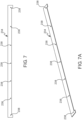
- the seed saver is provided with a plurality of openings 238 spaced apart along a length thereof and structured to receive the fasteners 236.
- the seed saver 234 is spaced from the infeed conveyor belt 222 about 3-30 mm including, e.g., 2, 4, 5, 6, 7, 8, 9, 10, 11, 12, 13, 14, 15, 16, 17, 18, 19, 20, 21, 22, 23, 24, 25, 26, 27, 28, 29, 31, 32, and 33 mm.
- the infeed conveyor includes upstanding lugs 240 extending substantially transverse to the direction of travel of the belt 222.
- the seed saver is spaced from the lugs about 3-30 mm.
- the seed saver is spaced from the lugs about 6-15 mm. Even more preferably, at their closest point the seed saver is spaced from the lugs about 10 mm.
- the seed saver can be a seed saver 334 adjustable in position relative to the main body.
- the seed saver 334 includes a slot 342 to receive a fastener attaching the seed saver to the main body.
- the seed saver 334 includes a plurality of slots 342 spaced apart along the length of the seed saver.
- the slot 342 of the seed saver has a longitudinal axis "LA S " extending substantially transverse to a longitudinal axis of the seed saver "LA SS ".
- the seed saver 234 or 334 can be formed from any material suitable to reduce loss of seeds or grain from the header during movement of the infeed conveyor belt 222.
- the seed saver or can comprise a metal, a composite or a polymer.
- the seed saver can also comprise an elastomeric material or fabric reinforced rubber, SBR rubber or neoprene rubber with fabric, e.g., polyester, insert.
- the seed saver is disposed adjacent the nose or fore end of the infeed conveyor belt to block unwanted expulsion of seeds or grain from the header. That is, the seed saver reduces the likelihood of seeds or grain being expelled from the header as the belt lugs 240 travel around the front roller 244 of the infeed conveyor 108 and engage seeds or grain delivered to the infeed conveyor from the lateral draper belts 120.
- the seed saver according to the subject disclosure is secured to the header without supplemental metal brackets and other associated mounting hardware.
Landscapes
- Life Sciences & Earth Sciences (AREA)
- Environmental Sciences (AREA)
- Pretreatment Of Seeds And Plants (AREA)
- Combines (AREA)
- Sowing (AREA)
Description
- The exemplary embodiments of present invention relate generally to a header of a plant cutting machine (e.g., a combine harvester) and, more specifically, to a header having an integrated seed saver which cooperates with a feeder belt to minimize seed loss from the header.
- An agricultural harvester e.g., a plant cutting machine, such as, but not limited to, a combine or a windrower, generally includes a header operable for severing and collecting plant or crop material as the harvester is driven over a crop field. The header has a plant cutting mechanism, e.g., a cutter bar, for severing the plants or crops via, for example, an elongate sickle mechanism that reciprocates sidewardly relative to a non-reciprocating guard structure. After crops are cut, they are collected inside the header and transported via conveyors such as a lateral draper belts and a central feeder draper belt towards a feederhouse located centrally inside the header.
- In conventional headers, projecting lugs of the moving feeder draper belt conveyor expel some of the seeds conveyed by the lateral draper belt conveyors from the header due to the absence of any structure to block the expulsion. This results in the seeds being lost and prevented from being harvested by the header.
- In accordance with an exemplary embodiment there is provided a header for an agricultural harvester comprising an infeed conveyor having a fore end and an aft end, a center knife drive disposed adjacent to and forwardly of the infeed conveyor, and a knife drive cover covering the center knife drive. The knife drive cover comprises a main body substantially covering an entire width of the center knife drive, and a seed saver, being a plate element extending rearwardly from an aft end of the main body. The seed saver is substantially planar, includes a width substantially coextensive with a width of the infeed conveyor, and defines a plane substantially parallel to a longitudinal axis of the infeed conveyor.
- In accordance with the exemplary embodiment, there is provided a header for an agricultural harvester including a knife drive cover comprising a main body substantially covering an entire width of a center knife drive, and a seed saver extending rearwardly from an aft end of the main body. The disclosure overcomes the disadvantages of conventional headers by providing a seed saver that is integrated with the knife drive cover.
- Other features and advantages of the subject disclosure will be apparent from the following more detail description of the exemplary embodiment.
- The foregoing summary, as well as the following detailed description of the exemplary embodiment of the subject disclosure, will be better understood when read in conjunction with the appended drawings. For the purpose of illustrating the present disclosure, there are shown in the drawings exemplary embodiments. It should be understood, however, that the subject application is not limited to the precise arrangements and instrumentalities shown.
-
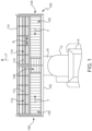
FIG. 1 is a top view of an agricultural harvester and a header in accordance with an exemplary embodiment of the subject disclosure; -
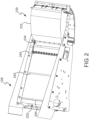
FIG. 2 is an end view of a portion of the agricultural harvester header ofFIG. 1 ; -
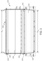
FIG. 3 is a top plan view of the portion of the agricultural harvester header ofFIG. 2 ; -
FIG. 4 is a perspective end view of the portion of the agricultural harvester header ofFIG. 2 with certain elements omitted for purposes of clarity; -
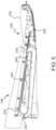
FIG. 5 is an end view of the portion of the agricultural harvester header ofFIG. 2 with certain elements omitted for purposes of clarity; -
FIG. 6 is a partial enlarged cross-sectional end view of the portion of the agricultural harvester header ofFIG. 2 with certain elements omitted for purposes of clarity; -
FIG. 7 is top plan view of a seed saver in accordance with an exemplary embodiment of the subject disclosure; -
FIG. 7A is a perspective view of the seed saver ofFIG. 7 ; and -
FIG. 8 is a partial enlarged top plan view of a seed saver in accordance with a further exemplary embodiment of the subject disclosure. - Reference will now be made in detail to the various exemplary embodiments of the subject disclosure illustrated in the accompanying drawings. Wherever possible, the same or like reference numbers will be used throughout the drawings to refer to the same or like features. It should be noted that the drawings are in simplified form and are not drawn to precise scale. Certain terminology is used in the following description for convenience only and is not limiting. Directional terms such as top, bottom, left, right, above, below and diagonal, are used with respect to the accompanying drawings. The term "distal" shall mean away from the center of a body. The term "proximal" shall mean closer towards the center of a body and/or away from the "distal" end. The words "inwardly" and "outwardly" refer to directions toward and away from, respectively, the geometric center of the identified element and designated parts thereof. Such directional terms used in conjunction with the following description of the drawings should not be construed to limit the scope of the subject application in any manner not explicitly set forth. Additionally, the term "a," as used in the specification, means "at least one." The terminology includes the words above specifically mentioned, derivatives thereof, and words of similar import.
- The terms "grain," "ear," "stalk," "leaf," and "crop material" are used throughout the specification for convenience and it should be understood that these terms are not intended to be limiting. Thus, "grain" refers to that part of a crop which is harvested and separated from discardable portions of the crop material. The header of the subject application is applicable to a variety of crops, including but not limited to wheat, soybeans and small grains. The terms "debris," "material other than grain," and the like are used interchangeably.
- "Exemplary" as used herein shall mean serving as an example.
- Referring now to the drawings, and more particularly to
FIG. 1 , there is shown an exemplary embodiment of anagricultural vehicle 10 in the form of, e.g., a combine harvester or agricultural harvester which generally includes achassis 12, a feeder housing orfeederhouse 14, and an attachment in the form of aheader 100. Typically, theagricultural harvester 10 includes additional internal systems for the separation and handling of collected crop material. However, these additional systems are not essential for a full and proper understanding of the subject disclosure. It should be appreciated that the draper belt described and illustrated herein does not necessarily need to be included on combine harvesters, but can be incorporated in other agricultural vehicles or devices having draper belts. - The
header 100 is coupled to, and supported by, thechassis 12 of theagricultural vehicle 10 by, for example, coupling to thefeeder housing 14. In the exemplary embodiment shown, theheader 100 is in the form of a draper header to harvest bushy or fluffy crop material. Theheader 100 has aframe 102 coupled to thechassis 12 by coupling to thefeeder housing 14 and a pair of opposedlateral ends header 100 may support one or more flexiblecutter bar assemblies 110 with reciprocatingknives 112 to cut crop material as theagricultural vehicle 10 travels in a forward direction, denoted by arrow F. The reciprocatingknives 112, which may be referred to as cutting elements, can be reciprocated back-and-forth in a lateral direction, denoted by arrow R, relative to the forward direction F in a known manner, e.g., by a wobble box, epicyclic drive, etc. Exemplary cutting elements applicable to the present exemplary embodiments are disclosed, e.g., inU.S. Patent Nos. 7,730,709 and8,151,547 . - The
header 100 further includes an infeedconveyor 108 that conveys the crop material into thefeeder housing 14. Theheader 100 may also include one or more lateral,flexible draper belts 120 that are positioned rearwardly of thecutter bar assemblies 110 and travel, e.g. rotate, in opposing directions of travel, denoted by each arrow "T", in order to convey crop material inwardly to the infeedconveyor 108 and thereby thefeeder housing 14. Theheader 100 may also include arotating reel 114 with tines or the like to sweep the crop material inwardly towards thedraper belts 120. - As shown in
FIGS. 2-6 , theinfeed conveyor 108 has abelt 222, afore end 224 and anaft end 226. A center knife drive 228 (FIG. 5 ) is disposed adjacent to and forwardly of the infeed conveyor, and aknife drive cover 230 covers the center knife drive. The knife drive cover comprises amain body 232 substantially covering an entire width of the center knife drive. The knife drive cover additionally comprises aseed saver 234 extending rearwardly from an aft end of themain body 232. As shown inFIG.3 , the seed saver is substantially planar and includes a width "WSS" substantially the same as or coextensive with a width "WIC" of theinfeed conveyor 108. The seed saver defines a plane (FIG. 6 ) substantially parallel to the infeed conveyor a longitudinal axis "A" of the infeed conveyor. - As best shown in
FIG. 6 , the seed saver is positioned above and forwardly of thebelt 222 of the infeedconveyor 108 and below themain body 232. Theseed saver 234 is integrated with themain body 232. According to an aspect, the seed saver can be integrally formed with the main body. According to another aspect, the seed saver can be attached to the main body by fasteners 236 (FIG. 6 ) including, without limitation, threaded fasteners or rivets. As shown inFIGS. 7 and 7A , the seed saver is provided with a plurality ofopenings 238 spaced apart along a length thereof and structured to receive thefasteners 236. - The
seed saver 234 is spaced from theinfeed conveyor belt 222 about 3-30 mm including, e.g., 2, 4, 5, 6, 7, 8, 9, 10, 11, 12, 13, 14, 15, 16, 17, 18, 19, 20, 21, 22, 23, 24, 25, 26, 27, 28, 29, 31, 32, and 33 mm. The infeed conveyor includesupstanding lugs 240 extending substantially transverse to the direction of travel of thebelt 222. According to an aspect, at the closest point of thelugs 240 to theseed saver 234 during movement of thebelt 222, the seed saver is spaced from the lugs about 3-30 mm. Preferably, at their closest point the seed saver is spaced from the lugs about 6-15 mm. Even more preferably, at their closest point the seed saver is spaced from the lugs about 10 mm. - According to another aspect, the seed saver can be a
seed saver 334 adjustable in position relative to the main body. In this regard, as shown inFIG. 8 , theseed saver 334 includes aslot 342 to receive a fastener attaching the seed saver to the main body. According to an aspect, theseed saver 334 includes a plurality ofslots 342 spaced apart along the length of the seed saver. Theslot 342 of the seed saver has a longitudinal axis "LAS" extending substantially transverse to a longitudinal axis of the seed saver "LASS". - The
seed saver infeed conveyor belt 222. For example, the seed saver or can comprise a metal, a composite or a polymer. The seed saver can also comprise an elastomeric material or fabric reinforced rubber, SBR rubber or neoprene rubber with fabric, e.g., polyester, insert. - According to the subject disclosure, the seed saver is disposed adjacent the nose or fore end of the infeed conveyor belt to block unwanted expulsion of seeds or grain from the header. That is, the seed saver reduces the likelihood of seeds or grain being expelled from the header as the belt lugs 240 travel around the
front roller 244 of theinfeed conveyor 108 and engage seeds or grain delivered to the infeed conveyor from thelateral draper belts 120. - Additionally, by being integrated into the main body of the knife drive cover, the seed saver according to the subject disclosure is secured to the header without supplemental metal brackets and other associated mounting hardware.
Claims (14)
- A header (100) for an agricultural harvester (10) comprising an infeed conveyor (108) having a fore end (224) and an aft end (226), a center knife drive (228) disposed adjacent to and forwardly of the infeed conveyor, and a knife drive cover (230) covering the center knife drive, the knife drive cover comprising a main body (232) substantially covering an entire width of the center knife drive, characterized by the knife drive cover further comprising:
a seed saver (234), being a plate element extending rearwardly from an aft end of the main body, wherein the seed saver is substantially planar, includes a width substantially coextensive with a width of the infeed conveyor, and defines a plane substantially parallel to the infeed conveyor. - A header according to claim 1, wherein the seed saver (234) is positioned above and forwardly of a belt (222) of the infeed conveyor.
- A header according to claim 1 or 2, wherein the seed saver (234) is positioned below the main body (232).
- A header according to any of the preceding claims, wherein the seed saver (234) is spaced from the infeed conveyor belt (222) about 3-30 mm.
- A header according to any of the preceding claims, wherein the infeed conveyor (108) includes lugs (240) and the seed saver (234) is spaced from the lugs about 3-30 mm.
- A header according to any of the preceding claims, wherein the infeed conveyor (108) includes lugs (240) and the seed saver (234) is spaced from the lugs about 6-15 mm.
- A header according to any of the preceding claims, wherein the infeed conveyor (108) includes lugs (240) and the seed saver (234) is spaced from the lugs about 10 mm.
- A header according to any of the preceding claims, wherein the seed saver (234) is integrally formed with the main body (232).
- A header according to any of the preceding claims, wherein the seed saver (234) is attached to the main body (232) by fasteners (236).
- A header according to any of the preceding claims, wherein the seed saver (234) is adjustable in position relative to the main body (232).
- A header according to any of the preceding claims, wherein the seed saver (234) includes a slot (342) to receive a fastener (236) attaching the seed saver to the main body (232).
- A header according to any of the preceding claims, wherein the slot (342) has a longitudinal axis (LAS) extending substantially transverse to a longitudinal axis (LASS) of the seed saver (234).
- A header according to any of the preceding claims, wherein the seed saver (234) comprises a metal, a composite, a polymer, an elastomeric material, fabric reinforced rubber, SBR rubber or neoprene rubber with fabric insert.
- An agricultural harvester (10) comprising a header (100) as claimed in any of the preceding claims.
Applications Claiming Priority (2)
| Application Number | Priority Date | Filing Date | Title |
|---|---|---|---|
| US202063084197P | 2020-09-28 | 2020-09-28 | |
| PCT/US2021/052413 WO2022067252A1 (en) | 2020-09-28 | 2021-09-28 | Header for an agricultural harvester having integral seed saver |
Publications (2)
| Publication Number | Publication Date |
|---|---|
| EP4216704A1 EP4216704A1 (en) | 2023-08-02 |
| EP4216704B1 true EP4216704B1 (en) | 2025-03-12 |
Family
ID=78303033
Family Applications (1)
| Application Number | Title | Priority Date | Filing Date |
|---|---|---|---|
| EP21795192.0A Active EP4216704B1 (en) | 2020-09-28 | 2021-09-28 | Header for an agricultural harvester having integral seed saver |
Country Status (5)
| Country | Link |
|---|---|
| US (1) | US20230363314A1 (en) |
| EP (1) | EP4216704B1 (en) |
| AR (1) | AR123561A1 (en) |
| BR (1) | BR112023005414A2 (en) |
| WO (1) | WO2022067252A1 (en) |
Families Citing this family (1)
| Publication number | Priority date | Publication date | Assignee | Title |
|---|---|---|---|---|
| US12653094B2 (en) * | 2023-04-05 | 2026-06-16 | Cnh Industrial America Llc | Cover assembly for a knife drive of an agricultural header |
Family Cites Families (24)
| Publication number | Priority date | Publication date | Assignee | Title |
|---|---|---|---|---|
| US1770709A (en) * | 1927-04-19 | 1930-07-15 | Caterpillar Tractor Co | Sickle guard |
| US2139927A (en) * | 1937-05-14 | 1938-12-13 | Joe H Bane | Sickle header for harvesters and the like |
| US2347365A (en) * | 1941-10-18 | 1944-04-25 | Deere & Co | Harvesting mechanism |
| DE3441209A1 (en) * | 1984-11-10 | 1986-05-15 | Claas Ohg, 4834 Harsewinkel | CUTTER BOX FOR HARVESTING MACHINES WITH FLEXIBLE CUTTER |
| US4722172A (en) * | 1985-02-04 | 1988-02-02 | Pearce Charles E | Harvesters |
| US4891932A (en) * | 1989-06-19 | 1990-01-09 | Johnson William A | Grain-saver dam for combine cutter bar |
| US20080276590A1 (en) * | 2006-02-10 | 2008-11-13 | Agco Corporation | Flexible draper and cutter bar with tilt arm for cutterbar drive |
| US20070193243A1 (en) * | 2006-02-10 | 2007-08-23 | Schmidt James R | Combine Harvester Draper Header Having Flexible Cutterbar |
| US7412816B2 (en) * | 2006-03-02 | 2008-08-19 | Deere & Company | Sectionalized belt guide for draper belt in an agricultural harvesting machine |
| US7730709B2 (en) | 2007-12-06 | 2010-06-08 | Cnh America Llc | Compact epicyclical drive |
| US7543428B1 (en) * | 2008-06-30 | 2009-06-09 | Deere & Company | Seamless draper belt |
| US8151547B2 (en) | 2009-10-02 | 2012-04-10 | Cnh America Llc | Blade assembly removal from a header of a plant cutting machine |
| US7958711B1 (en) * | 2010-06-16 | 2011-06-14 | Agco Corporation | Crop deflector for ends of draper belt of flexible draper header |
| US7908836B1 (en) * | 2010-07-20 | 2011-03-22 | Cnh America Llc | Draper header with multiple sided cut crop barrier interface between the cutter bar and draper canvas |
| RU2602842C2 (en) * | 2011-06-16 | 2016-11-20 | СиЭнЭйч ИНДАСТРИАЛ АМЕРИКА ЭлЭлСи | Cleaning flaps for blade central drive for plants cutting machine cutting device |
| US8479483B1 (en) * | 2011-12-27 | 2013-07-09 | Agco Corporation | Flexible draper head providing reduced crop residue accumulation |
| US8484939B1 (en) * | 2012-08-31 | 2013-07-16 | Macdon Industries Ltd. | Draper seal for crop harvesting header |
| CA2799093A1 (en) * | 2012-12-18 | 2014-06-18 | Honey Bee Manufacturing Ltd. | Draper seal for crop header |
| WO2014179309A1 (en) * | 2013-05-01 | 2014-11-06 | Cnh Industrial America Llc | Cutter guard assembly for a knife drive of an agricultural farm implement |
| US9961828B2 (en) * | 2013-05-10 | 2018-05-08 | Cnh Industrial America Llc | Cutter guard assembly cover of a header for an agricultural farm implement |
| US9591802B2 (en) * | 2015-04-28 | 2017-03-14 | Jose Luis Allochis | Belt sealing crop deflector for a flexible draper platform |
| US10813290B2 (en) * | 2018-06-11 | 2020-10-27 | Deere & Company | Component and method for crop ramp and belt support |
| US10918017B2 (en) * | 2018-07-10 | 2021-02-16 | Macdon Industries Ltd | Draper canvas seal |
| US11483971B2 (en) * | 2019-10-18 | 2022-11-01 | Cnh Industrial America Llc | Cutter bar support linkage |
-
2021
- 2021-09-21 AR ARP210102617A patent/AR123561A1/en active IP Right Grant
- 2021-09-28 BR BR112023005414A patent/BR112023005414A2/en unknown
- 2021-09-28 WO PCT/US2021/052413 patent/WO2022067252A1/en not_active Ceased
- 2021-09-28 US US18/028,622 patent/US20230363314A1/en active Pending
- 2021-09-28 EP EP21795192.0A patent/EP4216704B1/en active Active
Also Published As
| Publication number | Publication date |
|---|---|
| WO2022067252A1 (en) | 2022-03-31 |
| AR123561A1 (en) | 2022-12-14 |
| EP4216704A1 (en) | 2023-08-02 |
| BR112023005414A2 (en) | 2023-05-02 |
| US20230363314A1 (en) | 2023-11-16 |
Similar Documents
| Publication | Publication Date | Title |
|---|---|---|
| US10314234B2 (en) | Guide assembly for a lateral draper of a header for an agricultural harvester | |
| US10172280B2 (en) | Cutter guard assembly for knife drive of an agricultural farm implement | |
| EP3681265B1 (en) | Agricultural header with constant reel to cutter relationship | |
| US11589512B2 (en) | Draper support for a draper belt assembly of an agricultural harvester | |
| US20160135366A1 (en) | Cutter Guard Assembly Cover of a Header for an Agricultural Farm Implement | |
| EP4044791B1 (en) | Multi-segment header for an agricultural harvester | |
| US11647693B2 (en) | Stomping shoe assembly for an agricultural harvester header | |
| EP3434097B1 (en) | Crop divider for an agricultural harvester header having multiple harvesting reels | |
| US12495731B2 (en) | Cutter bar skid shoe for an agricultural harvester header | |
| US20240245002A1 (en) | Multi-segment header for an agricultural harvester | |
| US20230363314A1 (en) | Header for an agricultural harvester having integral seed saver | |
| EP3069595B1 (en) | Header for agricultural harvester equipped with dual cutter bar system | |
| US12507629B2 (en) | Center section reel for a header of an agricultural harvester | |
| US11297770B2 (en) | Draper belt assembly for an agricultural harvester | |
| US12501861B2 (en) | Draper belt assembly for an agricultural harvester header | |
| US20220279723A1 (en) | Rotatable wing dividers, harvesting headers, and agricultural machines having rotatable wing dividers | |
| US12484482B2 (en) | Crop ramp with belt guide roller for a header of an agricultural harvester | |
| CA3072370C (en) | Agricultural header with constant reel to cutter relationship |
Legal Events
| Date | Code | Title | Description |
|---|---|---|---|
| STAA | Information on the status of an ep patent application or granted ep patent |
Free format text: STATUS: UNKNOWN |
|
| STAA | Information on the status of an ep patent application or granted ep patent |
Free format text: STATUS: THE INTERNATIONAL PUBLICATION HAS BEEN MADE |
|
| PUAI | Public reference made under article 153(3) epc to a published international application that has entered the european phase |
Free format text: ORIGINAL CODE: 0009012 |
|
| STAA | Information on the status of an ep patent application or granted ep patent |
Free format text: STATUS: REQUEST FOR EXAMINATION WAS MADE |
|
| 17P | Request for examination filed |
Effective date: 20230428 |
|
| AK | Designated contracting states |
Kind code of ref document: A1 Designated state(s): AL AT BE BG CH CY CZ DE DK EE ES FI FR GB GR HR HU IE IS IT LI LT LU LV MC MK MT NL NO PL PT RO RS SE SI SK SM TR |
|
| DAV | Request for validation of the european patent (deleted) | ||
| DAX | Request for extension of the european patent (deleted) | ||
| GRAP | Despatch of communication of intention to grant a patent |
Free format text: ORIGINAL CODE: EPIDOSNIGR1 |
|
| STAA | Information on the status of an ep patent application or granted ep patent |
Free format text: STATUS: GRANT OF PATENT IS INTENDED |
|
| INTG | Intention to grant announced |
Effective date: 20241004 |
|
| GRAS | Grant fee paid |
Free format text: ORIGINAL CODE: EPIDOSNIGR3 |
|
| GRAA | (expected) grant |
Free format text: ORIGINAL CODE: 0009210 |
|
| STAA | Information on the status of an ep patent application or granted ep patent |
Free format text: STATUS: THE PATENT HAS BEEN GRANTED |
|
| AK | Designated contracting states |
Kind code of ref document: B1 Designated state(s): AL AT BE BG CH CY CZ DE DK EE ES FI FR GB GR HR HU IE IS IT LI LT LU LV MC MK MT NL NO PL PT RO RS SE SI SK SM TR |
|
| REG | Reference to a national code |
Ref country code: GB Ref legal event code: FG4D |
|
| REG | Reference to a national code |
Ref country code: CH Ref legal event code: EP |
|
| REG | Reference to a national code |
Ref country code: DE Ref legal event code: R096 Ref document number: 602021027584 Country of ref document: DE |
|
| REG | Reference to a national code |
Ref country code: IE Ref legal event code: FG4D |
|
| PG25 | Lapsed in a contracting state [announced via postgrant information from national office to epo] |
Ref country code: RS Free format text: LAPSE BECAUSE OF FAILURE TO SUBMIT A TRANSLATION OF THE DESCRIPTION OR TO PAY THE FEE WITHIN THE PRESCRIBED TIME-LIMIT Effective date: 20250612 |
|
| PG25 | Lapsed in a contracting state [announced via postgrant information from national office to epo] |
Ref country code: FI Free format text: LAPSE BECAUSE OF FAILURE TO SUBMIT A TRANSLATION OF THE DESCRIPTION OR TO PAY THE FEE WITHIN THE PRESCRIBED TIME-LIMIT Effective date: 20250312 |
|
| PG25 | Lapsed in a contracting state [announced via postgrant information from national office to epo] |
Ref country code: ES Free format text: LAPSE BECAUSE OF FAILURE TO SUBMIT A TRANSLATION OF THE DESCRIPTION OR TO PAY THE FEE WITHIN THE PRESCRIBED TIME-LIMIT Effective date: 20250312 |
|
| REG | Reference to a national code |
Ref country code: LT Ref legal event code: MG9D |
|
| PG25 | Lapsed in a contracting state [announced via postgrant information from national office to epo] |
Ref country code: NO Free format text: LAPSE BECAUSE OF FAILURE TO SUBMIT A TRANSLATION OF THE DESCRIPTION OR TO PAY THE FEE WITHIN THE PRESCRIBED TIME-LIMIT Effective date: 20250612 |
|
| PG25 | Lapsed in a contracting state [announced via postgrant information from national office to epo] |
Ref country code: HR Free format text: LAPSE BECAUSE OF FAILURE TO SUBMIT A TRANSLATION OF THE DESCRIPTION OR TO PAY THE FEE WITHIN THE PRESCRIBED TIME-LIMIT Effective date: 20250312 |
|
| REG | Reference to a national code |
Ref country code: NL Ref legal event code: MP Effective date: 20250312 |
|
| PG25 | Lapsed in a contracting state [announced via postgrant information from national office to epo] |
Ref country code: LV Free format text: LAPSE BECAUSE OF FAILURE TO SUBMIT A TRANSLATION OF THE DESCRIPTION OR TO PAY THE FEE WITHIN THE PRESCRIBED TIME-LIMIT Effective date: 20250312 |
|
| PG25 | Lapsed in a contracting state [announced via postgrant information from national office to epo] |
Ref country code: GR Free format text: LAPSE BECAUSE OF FAILURE TO SUBMIT A TRANSLATION OF THE DESCRIPTION OR TO PAY THE FEE WITHIN THE PRESCRIBED TIME-LIMIT Effective date: 20250613 Ref country code: BG Free format text: LAPSE BECAUSE OF FAILURE TO SUBMIT A TRANSLATION OF THE DESCRIPTION OR TO PAY THE FEE WITHIN THE PRESCRIBED TIME-LIMIT Effective date: 20250312 |
|
| REG | Reference to a national code |
Ref country code: AT Ref legal event code: MK05 Ref document number: 1774203 Country of ref document: AT Kind code of ref document: T Effective date: 20250312 |
|
| PG25 | Lapsed in a contracting state [announced via postgrant information from national office to epo] |
Ref country code: NL Free format text: LAPSE BECAUSE OF FAILURE TO SUBMIT A TRANSLATION OF THE DESCRIPTION OR TO PAY THE FEE WITHIN THE PRESCRIBED TIME-LIMIT Effective date: 20250312 |
|
| PG25 | Lapsed in a contracting state [announced via postgrant information from national office to epo] |
Ref country code: SE Free format text: LAPSE BECAUSE OF FAILURE TO SUBMIT A TRANSLATION OF THE DESCRIPTION OR TO PAY THE FEE WITHIN THE PRESCRIBED TIME-LIMIT Effective date: 20250312 |
|
| PG25 | Lapsed in a contracting state [announced via postgrant information from national office to epo] |
Ref country code: SM Free format text: LAPSE BECAUSE OF FAILURE TO SUBMIT A TRANSLATION OF THE DESCRIPTION OR TO PAY THE FEE WITHIN THE PRESCRIBED TIME-LIMIT Effective date: 20250312 |
|
| PG25 | Lapsed in a contracting state [announced via postgrant information from national office to epo] |
Ref country code: PT Free format text: LAPSE BECAUSE OF FAILURE TO SUBMIT A TRANSLATION OF THE DESCRIPTION OR TO PAY THE FEE WITHIN THE PRESCRIBED TIME-LIMIT Effective date: 20250714 |
|
| PGFP | Annual fee paid to national office [announced via postgrant information from national office to epo] |
Ref country code: DE Payment date: 20250926 Year of fee payment: 5 |
|
| PG25 | Lapsed in a contracting state [announced via postgrant information from national office to epo] |
Ref country code: PL Free format text: LAPSE BECAUSE OF FAILURE TO SUBMIT A TRANSLATION OF THE DESCRIPTION OR TO PAY THE FEE WITHIN THE PRESCRIBED TIME-LIMIT Effective date: 20250312 Ref country code: IT Free format text: LAPSE BECAUSE OF FAILURE TO SUBMIT A TRANSLATION OF THE DESCRIPTION OR TO PAY THE FEE WITHIN THE PRESCRIBED TIME-LIMIT Effective date: 20250312 |
|
| PG25 | Lapsed in a contracting state [announced via postgrant information from national office to epo] |
Ref country code: AT Free format text: LAPSE BECAUSE OF FAILURE TO SUBMIT A TRANSLATION OF THE DESCRIPTION OR TO PAY THE FEE WITHIN THE PRESCRIBED TIME-LIMIT Effective date: 20250312 |
|
| PGFP | Annual fee paid to national office [announced via postgrant information from national office to epo] |
Ref country code: FR Payment date: 20250925 Year of fee payment: 5 |
|
| PG25 | Lapsed in a contracting state [announced via postgrant information from national office to epo] |
Ref country code: CZ Free format text: LAPSE BECAUSE OF FAILURE TO SUBMIT A TRANSLATION OF THE DESCRIPTION OR TO PAY THE FEE WITHIN THE PRESCRIBED TIME-LIMIT Effective date: 20250312 Ref country code: EE Free format text: LAPSE BECAUSE OF FAILURE TO SUBMIT A TRANSLATION OF THE DESCRIPTION OR TO PAY THE FEE WITHIN THE PRESCRIBED TIME-LIMIT Effective date: 20250312 |
|
| PG25 | Lapsed in a contracting state [announced via postgrant information from national office to epo] |
Ref country code: RO Free format text: LAPSE BECAUSE OF FAILURE TO SUBMIT A TRANSLATION OF THE DESCRIPTION OR TO PAY THE FEE WITHIN THE PRESCRIBED TIME-LIMIT Effective date: 20250312 |
|
| PG25 | Lapsed in a contracting state [announced via postgrant information from national office to epo] |
Ref country code: SK Free format text: LAPSE BECAUSE OF FAILURE TO SUBMIT A TRANSLATION OF THE DESCRIPTION OR TO PAY THE FEE WITHIN THE PRESCRIBED TIME-LIMIT Effective date: 20250312 |
|
| PG25 | Lapsed in a contracting state [announced via postgrant information from national office to epo] |
Ref country code: IS Free format text: LAPSE BECAUSE OF FAILURE TO SUBMIT A TRANSLATION OF THE DESCRIPTION OR TO PAY THE FEE WITHIN THE PRESCRIBED TIME-LIMIT Effective date: 20250712 |
|
| REG | Reference to a national code |
Ref country code: DE Ref legal event code: R097 Ref document number: 602021027584 Country of ref document: DE |
|
| PG25 | Lapsed in a contracting state [announced via postgrant information from national office to epo] |
Ref country code: DK Free format text: LAPSE BECAUSE OF FAILURE TO SUBMIT A TRANSLATION OF THE DESCRIPTION OR TO PAY THE FEE WITHIN THE PRESCRIBED TIME-LIMIT Effective date: 20250312 |
|
| PLBE | No opposition filed within time limit |
Free format text: ORIGINAL CODE: 0009261 |
|
| STAA | Information on the status of an ep patent application or granted ep patent |
Free format text: STATUS: NO OPPOSITION FILED WITHIN TIME LIMIT |
|
| REG | Reference to a national code |
Ref country code: CH Ref legal event code: L10 Free format text: ST27 STATUS EVENT CODE: U-0-0-L10-L00 (AS PROVIDED BY THE NATIONAL OFFICE) Effective date: 20260121 |
|
| 26N | No opposition filed |
Effective date: 20251215 |
|
| REG | Reference to a national code |
Ref country code: CH Ref legal event code: H13 Free format text: ST27 STATUS EVENT CODE: U-0-0-H10-H13 (AS PROVIDED BY THE NATIONAL OFFICE) Effective date: 20260504 |
|
| PG25 | Lapsed in a contracting state [announced via postgrant information from national office to epo] |
Ref country code: LU Free format text: LAPSE BECAUSE OF NON-PAYMENT OF DUE FEES Effective date: 20250928 |
|
| GBPC | Gb: european patent ceased through non-payment of renewal fee |
Effective date: 20250928 |
|
| REG | Reference to a national code |
Ref country code: BE Ref legal event code: MM Effective date: 20250930 |
|
| PG25 | Lapsed in a contracting state [announced via postgrant information from national office to epo] |
Ref country code: LT Free format text: LAPSE BECAUSE OF FAILURE TO SUBMIT A TRANSLATION OF THE DESCRIPTION OR TO PAY THE FEE WITHIN THE PRESCRIBED TIME-LIMIT Effective date: 20250312 |
|
| PG25 | Lapsed in a contracting state [announced via postgrant information from national office to epo] |
Ref country code: MC Free format text: LAPSE BECAUSE OF FAILURE TO SUBMIT A TRANSLATION OF THE DESCRIPTION OR TO PAY THE FEE WITHIN THE PRESCRIBED TIME-LIMIT Effective date: 20250312 |
|
| PG25 | Lapsed in a contracting state [announced via postgrant information from national office to epo] |
Ref country code: GB Free format text: LAPSE BECAUSE OF NON-PAYMENT OF DUE FEES Effective date: 20250928 |
|
| PG25 | Lapsed in a contracting state [announced via postgrant information from national office to epo] |
Ref country code: CH Free format text: LAPSE BECAUSE OF NON-PAYMENT OF DUE FEES Effective date: 20250930 Ref country code: BE Free format text: LAPSE BECAUSE OF NON-PAYMENT OF DUE FEES Effective date: 20250930 Ref country code: IE Free format text: LAPSE BECAUSE OF NON-PAYMENT OF DUE FEES Effective date: 20250928 |