EP4216502A1 - Method for operating a broadband access network of a telecommunications network, the broadband access network comprising at least one central office point of delivery and the central office point of delivery, broadband access network or telecommunications network, system, software-defined interworking function, program and computer-readable medium - Google Patents
Method for operating a broadband access network of a telecommunications network, the broadband access network comprising at least one central office point of delivery and the central office point of delivery, broadband access network or telecommunications network, system, software-defined interworking function, program and computer-readable medium Download PDFInfo
- Publication number
- EP4216502A1 EP4216502A1 EP22153117.1A EP22153117A EP4216502A1 EP 4216502 A1 EP4216502 A1 EP 4216502A1 EP 22153117 A EP22153117 A EP 22153117A EP 4216502 A1 EP4216502 A1 EP 4216502A1
- Authority
- EP
- European Patent Office
- Prior art keywords
- delivery
- central office
- office point
- management system
- zero touch
- Prior art date
- Legal status (The legal status is an assumption and is not a legal conclusion. Google has not performed a legal analysis and makes no representation as to the accuracy of the status listed.)
- Granted
Links
Images

Classifications
-
- H—ELECTRICITY
- H04—ELECTRIC COMMUNICATION TECHNIQUE
- H04L—TRANSMISSION OF DIGITAL INFORMATION, e.g. TELEGRAPHIC COMMUNICATION
- H04L41/00—Arrangements for maintenance, administration or management of data switching networks, e.g. of packet switching networks
- H04L41/08—Configuration management of networks or network elements
- H04L41/0803—Configuration setting
- H04L41/0806—Configuration setting for initial configuration or provisioning, e.g. plug-and-play
- H04L41/0809—Plug-and-play configuration
Definitions
- the present invention relates a method for operating a broadband access network of a telecommunications network, the broadband access network comprising at least one central office point of delivery and the central office point of delivery comprising or being assigned or having access to an access orchestrator entity or functionality, and an element management system entity or functionality, wherein the telecommunications network furthermore also comprises a plurality of customer premises equipment entities serving or being related to one or a plurality of end users or subscribers of the telecommunications network, wherein the telecommunications network additionally comprises or is assigned or related to an operations management system, the operations management system providing zero touch provisioning functionality regarding at least one specific customer premises equipment entity.
- the present invention relates to a broadband access network or telecommunications network comprising a broadband access network, the broadband access network comprising at least one central office point of delivery and the central office point of delivery comprising or being assigned or having access to an access orchestrator entity or functionality, and an element management system entity or functionality, wherein the telecommunications network furthermore also comprises a plurality of customer premises equipment entities serving or being related to one or a plurality of end users or subscribers of the telecommunications network, wherein the telecommunications network additionally comprises or is assigned or related to an operations management system, the operations management system providing zero touch provisioning functionality regarding at least one specific customer premises equipment entity.
- the present invention relates to a system for operating a broadband access network of a telecommunications network, the system comprising the telecommunications network and the broadband access network, the broadband access network comprising at least one central office point of delivery and the central office point of delivery comprising or being assigned or having access to an access orchestrator entity or functionality, and an element management system entity or functionality, wherein the telecommunications network furthermore also comprises a plurality of customer premises equipment entities serving or being related to one or a plurality of end users or subscribers of the telecommunications network, wherein the telecommunications network additionally comprises or is assigned or related to an operations management system, the operations management system providing zero touch provisioning functionality regarding at least one specific customer premises equipment entity.
- the present invention relates to a software-defined interworking function proxy or central office point of delivery comprising a software-defined interworking function proxy provided to be used as part of an inventive system or as part of an inventive broadband access network or telecommunications network.
- the present invention relates to a program and to a computer-readable medium for operating a broadband access network of a telecommunications network, the broadband access network comprising at least one central office point of delivery.
- An object of the present invention is to provide a technically simple, effective and cost effective solution for operating a broadband access network of a telecommunications network, the broadband access network comprising at least one central office point of delivery and the central office point of delivery comprising or being assigned or having access to an access orchestrator entity or functionality, and an element management system entity or functionality, wherein the telecommunications network furthermore also comprises a plurality of customer premises equipment entities serving or being related to one or a plurality of end users or subscribers of the telecommunications network, and wherein the telecommunications network additionally comprises or is assigned or related to an operations management system, the operations management system providing zero touch provisioning functionality regarding at least one specific customer premises equipment entity, wherein the incompatibility or incompatibilities of vendor-specific solutions with other solutions is/are minimized by integrating the vendor-specific solutions with the cloud central office infrastructure (central office point of delivery).
- a further object of the present invention is to provide a corresponding broadband access network or corresponding telecommunications network, a corresponding system, a corresponding software-defined interworking function proxy or a corresponding central office point of delivery comprising a software-defined interworking function proxy.
- the object of the present invention is achieved by a method for operating a broadband access network of a telecommunications network, the broadband access network comprising at least one central office point of delivery and the central office point of delivery comprising or being assigned or having access to an access orchestrator entity or functionality, and an element management system entity or functionality, wherein the telecommunications network furthermore also comprises a plurality of customer premises equipment entities serving or being related to one or a plurality of end users or subscribers of the telecommunications network, wherein the telecommunications network additionally comprises or is assigned or related to an operations management system, the operations management system providing zero touch provisioning functionality regarding at least one specific customer premises equipment entity, wherein the method comprises the following steps:
- the vendor-specific solutions are integrated within the cloud of central office infrastructure (i.e. the interconnected central office points of delivery).
- the vendor-specific virtual network functions are hosted in the central office point of delivery infrastructure and the existing interfaces are able to be used by means of intercepting zero touch provisioning messages, i.e. a (first) zero touch provisioning message that is directed to or intended to be received by the operations management system (especially vendor-specific) is received by the central office point of delivery, and the central office point of delivery transmits the (first) zero touch provisioning message to the operations management system.
- the virtual network functions benefit from the capabilities (e.g., lifecycle processes, parameterization, networking) of the infrastructure (i.e. especially the infrastructure of (or cloud of) the central office points of delivery). Due to the capabilities of the central office point of delivery elements, this enables a significantly higher collaboration of the software-defined components with the provider network.
- the introduction of software-defined vendor abstraction function eliminates the separation into underlay and overlay services associated with conventional software-defined wide area network solutions. It also enables the continuation and improvement of already implemented network management and control processes for all (network) elements. This is particularly important for lifecycle operations at customer sites, for which the greatest possible automation is sought.
- SD-CPEs software-defined customer premises equipment entities
- SD-Control software-defined control
- SD-WAN software-defined wide area network
- SD-WAN Edge CPE also called SD-CPE
- SD-WAN Access also called SD-Access, or corresponding virtual network function
- Central office point of delivery elements are network elements with a spine-leaf architecture that are controlled by a cross-domain element management system (i.e.
- the present invention provides a solution such that interaction between software-defined customer premises equipment entities (SD-CPEs), the software-defined access elements, and the software-defined control (SD-Control) are able to interoperate, also across different vendor's equipment or components, thereby realizing an interaction below the domain controller, namely between the element management layer and the network element layer to directly achieve the principles of disaggregation and abstraction below the domain controller in the software-defined (SDx) context.
- SD-CPEs software-defined customer premises equipment entities
- SD-Control software-defined control
- SD VAF software-defined vendor abstraction function
- the telecommunications network according to the present invention might be a fixed-line telecommunications network or a mobile communication network but could also have both aspects, i.e. parts of a fixed-line telecommunications network (or being a fixed-line telecommunications network in such parts) and parts of a mobile communication network (or being a mobile communication network in such parts); such networks are also known under the term fixed-mobile-convergence networks (FMC networks).
- FMC networks fixed-mobile-convergence networks
- the presented invention can be applied in both fixed disaggregated networks (e.g. ONF (Open Network Foundation) SEBA (SDN-Enabled Broadband Access) 2.0) and mobile networks (e.g. via 5G, 6G), as well as in hybrid mixed forms.
- the operations management system transmits a second zero touch provisioning message, the second zero touch provisioning message being directed to or intended to be received by the specific customer premises equipment, wherein the second zero touch provisioning message is received by the central office point of delivery, and wherein the central office point of delivery transmits the second zero touch provisioning message to the specific customer premises equipment.
- the operations management system transmitting the second zero touch provisioning message, the second zero touch provisioning message being directed to or intended to be received by the specific customer premises equipment, the second zero touch provisioning message being received by the central office point of delivery, and the central office point of delivery 110 transmitting the second zero touch provisioning message to the specific customer premises equipment, it is advantageously possible to also intercept second zero touch provisioning messages, i.e. zero touch provisioning messages being directed towards the specific customer premises equipment.
- the central office point of delivery especially the access orchestrator entity or functionality and/or the element management system entity or functionality, comprises a zero touch provisioning detection entity or functionality, wherein the zero touch provisioning detection entity or functionality intercepts the first zero touch provisioning message directed to or intended to be received by the operations management system and/or the second zero touch provisioning message received from the operations management system.
- the access orchestrator entity or functionality and/or the element management system entity or functionality comprising a zero touch provisioning detection entity or functionality intercepting the first zero touch provisioning message directed to or intended to be received by the operations management system and/or the second zero touch provisioning message received from the operations management system, it is advantageously possible to easily and effectively implement the inventive method.
- the telecommunications network comprises a further central office point of delivery, wherein the plurality of customer premises equipment entities are physically connected to the further central office point of delivery, wherein especially the further central office point of delivery forwards the first zero touch provisioning message, being directed to or intended to be received by the operations management system, to the central office point of delivery.
- the further central office point of delivery (in addition to the central office point of delivery) especially providing the physical connection for the plurality of customer premises equipment entities, it is advantageously possible that the further central office point of delivery is used for connecting the plurality of customer premises equipment entities, and the central office point of delivery is used for intercepting the first and/or second zero touch provisioning message.
- the first zero touch provisioning message and/or the second zero touch provisioning message corresponds to a zero touch provisioning ident message.
- the first zero touch provisioning message and/or the second zero touch provisioning message are involved in a lookup-procedure and/or a first-sign-of-life-procedure, wherein especially the first zero touch provisioning message and/or the second zero touch provisioning message reflects a subscriber-related modification and/or a network-related modification of the specific customer premises equipment.
- the first zero touch provisioning message and/or the second zero touch provisioning message are involved in a management procedure and/or or an inventory procedure, especially transporting templates for the specific customer premises equipment, and especially regarding quality-of-service and/or routing and/or credentials.
- the central office point of delivery especially the zero touch provisioning detection entity or functionality, realizes a software-defined interworking function proxy, especially comprising a vendor-abstraction entity or functionality regarding the specific customer premises equipment and/or a vendor-abstraction entity or functionality regarding the operations management system.
- the central office point of delivery especially the zero touch provisioning detection entity or functionality, realizing the software-defined interworking function proxy, especially comprising a vendor-abstraction entity or functionality regarding the specific customer premises equipment and/or a vendor-abstraction entity or functionality regarding the operations management system, it is advantageously possible to easily and effectively implement the inventive method.
- the telecommunications network additionally comprises or is assigned or related to a further operations management system, the further operations management system providing zero touch provisioning functionality regarding at least one further specific customer premises equipment entity, wherein the method furthermore comprises the steps of:
- the present invention relates to a broadband access network or telecommunications network comprising a broadband access network, the broadband access network comprising at least one central office point of delivery and the central office point of delivery comprising or being assigned or having access to an access orchestrator entity or functionality, and an element management system entity or functionality,
- the present invention relates to a system for operating a broadband access network of a telecommunications network, the system for operating a broadband access network of a telecommunications network, the system comprising the telecommunications network and the broadband access network, the broadband access network comprising at least one central office point of delivery and the central office point of delivery comprising or being assigned or having access to an access orchestrator entity or functionality, and an element management system entity or functionality, wherein the telecommunications network furthermore also comprises a plurality of customer premises equipment entities serving or being related to one or a plurality of end users or subscribers of the telecommunications network,
- the present invention relates to a software-defined interworking function proxy or central office point of delivery comprising a software-defined interworking function proxy provided to be used as part of an inventive system or as part of an inventive broadband access network or telecommunications network.
- the present invention relates to a program comprising a computer readable program code which, when executed on a computer and/or on a network node of a telecommunications network and/or on a software-defined interworking function proxy of a central office point of delivery, or in part on the network node of a telecommunications network and/or in part on the software-defined interworking function proxy of a central office point of delivery, causes the computer and/or the network node of the telecommunications network and/or the software-defined interworking function proxy of the central office point of delivery to perform the inventive method.
- the present invention relates to a computer-readable medium comprising instructions which when executed on a computer and/or on a network node of a telecommunications network and/or on a software-defined interworking function proxy of a central office point of delivery, or in part on the network node of a telecommunications network and/or in part on the software-defined interworking function proxy of a central office point of delivery, causes the computer and/or the network node of the telecommunications network and/or the software-defined interworking function proxy of the central office point of delivery to perform the inventive method.
- first, second, third and the like in the description and in the claims are used for distinguishing between similar elements and not necessarily for describing a sequential or chronological order; this is especially the case for the terms “first step”, “second step”, etc. It is to be understood that the terms so used are interchangeable under appropriate circumstances and that the embodiments of the invention described herein are capable of operation in other sequences than described or illustrated herein.
- a telecommunications network 100 is schematically shown, having - preferably - at least a fixed line part.
- a mobile (or cellular) part might be present as well, as part of the telecommunications network 100, but is not specifically illustrated in Figure 1 .
- User equipments or client devices 51, 52 are connected to the telecommunications network 100 by means of a (broadband) access network 120.
- the telecommunications network 100 comprises, especially as part of the broadband access network 120, at least one logical or physical central office point of delivery 110 that is preferably realized within a (mini) data center and that is especially handling different access requirements, especially different access possibilities, of the client devices 51, 52 to network functionalities provided by the telecommunications network 100 or via the telecommunications network 100.
- the telecommunications network 100 typically also comprises - besides the broadband access network 120 - a core network 101.
- the client devices 51, 52 are typically connected to the logical or physical central office point of delivery 110 by means of a customer premises equipment device 50, 50', 50" or by means of a customer premises equipment entity or functionality that might be built into or realized by the client devices 51, 52.
- the central office point of delivery 110 comprises a switching fabric 115 comprising a plurality of spine network nodes and typically also a plurality of leaf network nodes which are not explicitly represented in Figure 1 .
- the telecommunications network 100 furthermore also comprises a business and/or operations support system 105.
- FIG. 2 schematically illustrates a central office point of delivery 110 as part of a broadband access network 120 of a telecommunications network 100.
- the represented part of the telecommunications network 100 (or the central office point of delivery 110) comprises, especially as part of a control functionality or control plane 180, an access orchestrator entity or functionality 181 and at least one element management system entity or functionality 182.
- the central office point of delivery 110 comprises typically and preferably (but not necessarily) a plurality of access nodes 151, 152, 153 (or also called line termination nodes 151, 152, 153) as part of an access functionality 150.
- the broadband access network 120 comprises three access nodes, a first access node 151, a second access node 152, and a third access node 153.
- the access nodes 151, 152, 153 might be provided to support different access technologies to the customer premises equipment entities or functionalities 50, 50', 50"; the customer premises equipment entity or functionality 50, 50', 50" might also be called a home gateway or a cable modem or an integrated access device 50, 50', 50".
- a client device 51 (or a plurality of client devices which are not specifically represented in Figure 2 ) is (or are) connected to the telecommunications network 100 (especially to the first access node 151 or hybrid fiber coaxial network equipment) via the customer premises equipment entity or functionality 50, 50', 50".
- the functionality of the client device 51 and the functionality of the customer premises equipment entity or functionality 50, 50', 50" (or home gateway device 50, 50', 50" or cable modem 50, 50', 50" might be integrated in one device or "box”. Nevertheless, these functionalities are represented in Figure 2 as separated functionalities. In Figure 2 , only one cable modem device 50 (or customer premises equipment 50) (i.e. a specific customer premises equipment), and only one client device 51 are shown. However, also the second and/or third access nodes 152, 153 typically provide network access to end users or customers and the respective customer premises equipment devices or integrated access devices (not shown in Figure 2 ).
- the central office point of delivery 110 comprises a switching fabric 115 as a transport functionality or service 115 within the central office point of delivery 110.
- the switching fabric 115 (or transport functionality or service 115) comprises a plurality of spine network nodes 171, 172 and a plurality of leaf network nodes 161, 162, 163, the leaf network nodes 161, 162, 163 (i.e., according to the exemplary embodiment shown in Figure 2 , a first leaf network node 161, a second leaf network node 162, and a third leaf network node 163) especially providing the edge functionality or service 160 within the central office point of delivery 110.
- the access nodes 151, 152, 153 are serving or being related to one or a plurality of end users or subscribers (and the corresponding customer premises equipment devices or entities or functionalities and client devices) of the telecommunications network 100; for the sake of simplicity, Figure 2 only shows one customer premises equipment entity or functionality 50 and one client device 51, being connected to the first access node 151 of the central office point of delivery 110.
- a method for operating a broadband access network 120 of a telecommunications network 100 comprising at least one central office point of delivery 110 and the central office point of delivery 110 comprising or being assigned to or having access to an access orchestrator entity or functionality 181, and an element management system entity or functionality 182.
- the telecommunications network 100 furthermore also comprises a plurality of customer premises equipment entities 50, 50', 50" serving or being related to one or a plurality of end users or subscribers of the telecommunications network.
- the telecommunications network 100 comprises or is assigned to or related to an operations management system 105 (especially of a specific vendor or manufacturer), the operations management system 105 providing zero touch provisioning functionality regarding at least one specific customer premises equipment entity 50 (i.e. the specific customer premises equipment entity 50 being also provided by the specific vendor or manufacturer).
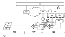
- FIG. 3 This is schematically shown in Figure 3 that illustrates the infrastructure of the central office point of delivery 110 or the plurality of central office points of delivery 110, 110', the element management system 182 as well as schematically the access domain 120', the core network domain 101' as well as the service domain 130' of the telecommunications network 100.
- the customer premises equipment entities or functionalities 50, 50', 50" are shown as part of the access domain 120'.
- the telecommunications network 100 comprises (especially the central office point of delivery 110 comprises) virtual network functions 55, 55', 55" corresponding to the customer premises equipment entities or functionalities 50, 50', 50", wherein especially a specific or first customer premises equipment entity or functionality 50 corresponds to (or interacts with) a specific or first virtual network function 55, a second customer premises equipment entity or functionality 50' corresponds to (or interacts with) a second virtual network function 55' and a third customer premises equipment entity or functionality 50" corresponds to (or interacts with) a third virtual network function 55".
- Such zero touch provisioning messages are schematically represented, in Figure 3 , by means of reference signs 220 and 221 (and corresponding arrows), reference sign 220 being used for zero touch provisioning messages, in the context of the present invention also called first zero touch provisioning messages, travelling (or being transmitted) in the direction from the (specific) customer premises equipment entity or functionality 50 towards the operations management system 105, and reference sign 221 being used for zero touch provisioning messages, in the context of the present invention also called second zero touch provisioning messages, travelling (or being transmitted) in the direction from the operations management system 105 towards the (specific) customer premises equipment entity or functionality 50.
- This exchange especially occurs in case that all these entities concerned are provided by one specific vendor or manufacturer (or conform to a specific communication protocol, defined by the respective vendor).
- This also means, that different kinds or different groups of specific customer premises equipment entities or functionalities 50, 50', 50" (each such kind being related to or provided by another vendor or manufacturer) might be present in the telecommunications network 100, and that regarding each such different kind or different group of specific customer premises equipment entities or functionalities 50, 50', 50", there might be a (or at least one) different operations management system 105 present, each such operations management system 105 being related or provided by another specific vendor or manufacturer (or conform to a corresponding specific communication protocol, defined by the respective vendor).
- the inventive method comprises the steps of:
- the first zero touch provisioning message(s) 220 typically being transmitted by the specific customer premises equipment entity 50, and being directed to or intended to be received by the operations management system 105.
- the first zero touch provisioning message(s) 220 might be (but is/are not necessarily) modified by the central office point of delivery 110, e.g. an address field or address value exchanged or modified.
- the operations management system 105 transmits a second zero touch provisioning message 221, the second zero touch provisioning message 221 being directed to or intended to be received by the specific customer premises equipment 50, and the second zero touch provisioning message 221 is received by the central office point of delivery 110, and the central office point of delivery 110 transmits the second zero touch provisioning message 221 to the specific customer premises equipment 50.
- the second zero touch provisioning message(s) 221 typically being transmitted by the operations management system 105 and being directed to or intended to be received by the specific customer premises equipment entity 50.
- the second zero touch provisioning message(s) 221 might likewise be (but is/are not necessarily) modified by the central office point of delivery 110, e.g. an address field or address value exchanged or modified.
- the telecommunications network 100 or the (or one or a plurality of) central office point(s) of delivery 110) to manage or to handle events or processes of the customer premises equipment entities or functionalities 50, 50', 50" such as: show up, management and/or inventory processes in a vendor-abstracted manner.
- the central office point of delivery 110 comprises a zero touch provisioning detection entity or functionality, wherein the zero touch provisioning detection entity or functionality intercepts the first zero touch provisioning message(s) 220 directed to or intended to be received by the operations management system 105 and/or the second zero touch provisioning message 221 received from the operations management system 105.
- the telecommunications network 100 comprises not only one central office point of delivery (i.e. the central office point of delivery 110 that is also called the considered central office point of delivery) but a plurality of central office points of delivery, i.e. besides the (considered, or also called specific) central office point of delivery 110, there is at least one, but preferably a plurality of further central office points of delivery.
- a further central office point of delivery 110' is schematically designated, in Figure 1 , by reference sign 110'.
- the zero touch provisioning detection entity or functionality intercepting the first and/or second zero touch provisioning messages 220, 221 does not need to be located in the same central office point of delivery 110 than the one to which the plurality of customer premises equipment entities 50, 50', 50" are physically connected, i.e.
- these customer premises equipment entities 50, 50', 50" might be physically connected (or logically assigned) to the further central office point of delivery 110', while still central office point of delivery 110 (or, rather, its zero touch provisioning detection entity or functionality) intercepts the first and/or second zero touch provisioning messages 220, 221; in this case, especially, the further central office point of delivery 110' (to which the customer premises equipment entities 50, 50', 50" are assumed to be physically connected (or logically assigned)) forwards the respective first zero touch provisioning message 220, being directed to or intended to be received by the operations management system 105, to the central office point of delivery 110 which does the intercepting operation, and, if application, the modification of the respective first zero touch provisioning message(s).
- a second zero touch provisioning message 221 (or a plurality of such second zero touch provisioning messages 221), after intercepting at the central office point of delivery 110, the respective message(s) is/are forwarded to the further central office point of delivery 110'.
- the central office point of delivery 110 especially the zero touch provisioning detection entity or functionality, realizes a software-defined interworking function proxy 106, especially comprising a vendor-abstraction entity or functionality 106' regarding the specific customer premises equipment 50 and/or a vendor-abstraction entity or functionality 106" regarding the (specific or vendor-specific) operations management system 105.
- the telecommunications network 100 additionally comprises or is assigned or related to a further (specific or vendor-specific) operations management system, the further operations management system providing zero touch provisioning functionality regarding at least one further specific customer premises equipment entity (or a further group of specific customer premises equipment entities), and wherein the method furthermore comprises the steps of:
- the vendor-specific solutions within the cloud of central office infrastructure (i.e. the interconnected central office points of delivery 110, 100').
- the vendor-specific virtual network functions 55, 55', 55" are hosted in the central office point of delivery infrastructure (e.g. the central office point of delivery 110) and the existing interfaces (cf. reference sign 2 in Figure 3 ) are able to be used by means of intercepting zero touch provisioning messages 220, 221, i.e.
- a first zero touch provisioning message 220 that is (transmitted by the specific customer premises equipment entity 50, and) directed to or intended to be received by the (especially vendor-specific) operations management system 105 is received by the central office point of delivery 110 (or, its zero touch provisioning detection entity or functionality), and the central office point of delivery 110 transmits the first zero touch provisioning message 220 to the operations management system 105; likewise a second zero touch provisioning message 221 travelling or being transmitted in opposite direction is able to be intercepted.
- the virtual network functions 55, 55', 55" benefit from the capabilities (e.g., lifecycle processes, parameterization, networking) of the infrastructure of the central office points of delivery 110, 110'.
- the introduction of software-defined vendor abstraction function i.e. the software-defined interworking function proxy 106, especially comprising the vendor-abstraction entity or functionality 106' regarding the specific customer premises equipment 50 and/or a vendor-abstraction entity or functionality 106" regarding the (specific or vendor-specific) operations management system 105) eliminates the separation into underlay and overlay services associated with conventional software-defined wide area network solutions. It also enables the continuation and improvement of already implemented network management and control processes for all (network) elements. This is particularly important for lifecycle operations at customer sites, for which the greatest possible automation is sought.
- the control plane / management plane vendor abstraction function (CP/MP-VAF), or software-defined interworking function proxy 106, is connected to the POD infrastructure (i.e. especially to the central office point of delivery 110), cf. reference sign 3 in Figure 3 .
- the service knowledge of the central office point of delivery 110 or central office point of delivery infrastructure is available to the CP/MP-VAF / software-defined interworking function proxy 106.
- Existing interfaces with OSS/BSS levels at the central office point of delivery level do not need to be adapted to individual manufacturers for the use of manufacturer-specific virtual network functions 55, 55', 55"; adaptation of the CP/MP-VAF / software-defined interworking function proxy 106 to the manufacturer / vendor is sufficient.
- the CP/MP-VAF / software-defined interworking function proxy 106 enables the virtual network function(s) 55, 55', 55" and the customer premises equipment entities 50, 50', 50" (especially virtual customer premises equipment entities, vCPE) to be set to fit exactly, especially by means of in-band management, cf. reference sign 5 in Figure 3 .
- EMS-SD-VAF element management system software-defined vendor abstraction function
- the element management system 182 decouples the element management system 182 and the (specific or operator-specific) operations management system 105 from each other.
- Service control mechanisms running in the levels above the operations management system 105 do not have to be adapted to vendor-specific peculiarities in the upper elements (e.g., in the element management system EMS, 182).
- the EMS-SD-VAF vendor-abstraction entity or functionality 106
- the EMS-SD-VAF has a knowledge of services and users so that it can enable the respective operations management system 105 to provide appropriate instructions and settings.
- the EMS-SD-VAF (vendor-abstraction entity or functionality 106") is the linking or interweaving of service information with network-specific information, which is merged from vendor-specific virtual network functions 55, 55', 55" and customer premises equipment entities 50, 50', 50" (or vCPEs), as well as from network elements (central office point of delivery 110, 110') of the provider.
- This enables cross-vendor services, settings and procedures; examples include, e.g., forwarding, accounting, quality-of-service, service rules, uniform service templates or the like.
Landscapes
- Engineering & Computer Science (AREA)
- Computer Networks & Wireless Communication (AREA)
- Signal Processing (AREA)
- Data Exchanges In Wide-Area Networks (AREA)
Abstract
wherein the telecommunications network furthermore also comprises a plurality of customer premises equipment entities serving or being related to one or a plurality of end users or subscribers of the telecommunications network,
wherein the telecommunications network additionally comprises or is assigned or related to an operations management system, the operations management system providing zero touch provisioning functionality regarding at least one specific customer premises equipment entity,
wherein the method comprises the following steps:
-- in a first step, a first zero touch provisioning message that is directed to or intended to be received by the operations management system is received by the central office point of delivery,
-- in a second step, the central office point of delivery transmits the first zero touch provisioning message to the operations management system.
Description
- The present invention relates a method for operating a broadband access network of a telecommunications network, the broadband access network comprising at least one central office point of delivery and the central office point of delivery comprising or being assigned or having access to an access orchestrator entity or functionality, and an element management system entity or functionality, wherein the telecommunications network furthermore also comprises a plurality of customer premises equipment entities serving or being related to one or a plurality of end users or subscribers of the telecommunications network, wherein the telecommunications network additionally comprises or is assigned or related to an operations management system, the operations management system providing zero touch provisioning functionality regarding at least one specific customer premises equipment entity.
- Furthermore, the present invention relates to a broadband access network or telecommunications network comprising a broadband access network, the broadband access network comprising at least one central office point of delivery and the central office point of delivery comprising or being assigned or having access to an access orchestrator entity or functionality, and an element management system entity or functionality, wherein the telecommunications network furthermore also comprises a plurality of customer premises equipment entities serving or being related to one or a plurality of end users or subscribers of the telecommunications network, wherein the telecommunications network additionally comprises or is assigned or related to an operations management system, the operations management system providing zero touch provisioning functionality regarding at least one specific customer premises equipment entity.
- Additionally, the present invention relates to a system for operating a broadband access network of a telecommunications network, the system comprising the telecommunications network and the broadband access network, the broadband access network comprising at least one central office point of delivery and the central office point of delivery comprising or being assigned or having access to an access orchestrator entity or functionality, and an element management system entity or functionality, wherein the telecommunications network furthermore also comprises a plurality of customer premises equipment entities serving or being related to one or a plurality of end users or subscribers of the telecommunications network, wherein the telecommunications network additionally comprises or is assigned or related to an operations management system, the operations management system providing zero touch provisioning functionality regarding at least one specific customer premises equipment entity.
- Additionally, the present invention relates to a software-defined interworking function proxy or central office point of delivery comprising a software-defined interworking function proxy provided to be used as part of an inventive system or as part of an inventive broadband access network or telecommunications network.
- Furthermore, the present invention relates to a program and to a computer-readable medium for operating a broadband access network of a telecommunications network, the broadband access network comprising at least one central office point of delivery.
- The exchange of packetized information in broadband communication systems or telecommunications networks, both in fixed-line as in wireless communication systems (or fixed-line communication networks and mobile communication networks) has already grown dramatically and probably will also grow in the future due to the rapid spread of different data services in such communication networks.
- In conventionally known or current telecommunications network or central office point of delivery design architectures, especially in view of software-defined wide area network applications or a software-defined wide area network application scenario, there are typically software-defined customer premises equipment devices or components, software-defined access elements and software-defined control entities or functionalities that are typically optimized for each vendor's components. Such software-defined wide area network solutions (especially of different vendors) are only compatible with each other to a limited extent or not at all across manufacturers. This often results in a real coupling among existing network elements cannot be realized.
- An object of the present invention is to provide a technically simple, effective and cost effective solution for operating a broadband access network of a telecommunications network, the broadband access network comprising at least one central office point of delivery and the central office point of delivery comprising or being assigned or having access to an access orchestrator entity or functionality, and an element management system entity or functionality, wherein the telecommunications network furthermore also comprises a plurality of customer premises equipment entities serving or being related to one or a plurality of end users or subscribers of the telecommunications network, and wherein the telecommunications network additionally comprises or is assigned or related to an operations management system, the operations management system providing zero touch provisioning functionality regarding at least one specific customer premises equipment entity, wherein the incompatibility or incompatibilities of vendor-specific solutions with other solutions is/are minimized by integrating the vendor-specific solutions with the cloud central office infrastructure (central office point of delivery). A further object of the present invention is to provide a corresponding broadband access network or corresponding telecommunications network, a corresponding system, a corresponding software-defined interworking function proxy or a corresponding central office point of delivery comprising a software-defined interworking function proxy.
- The object of the present invention is achieved by a method for operating a broadband access network of a telecommunications network, the broadband access network comprising at least one central office point of delivery and the central office point of delivery comprising or being assigned or having access to an access orchestrator entity or functionality, and an element management system entity or functionality, wherein the telecommunications network furthermore also comprises a plurality of customer premises equipment entities serving or being related to one or a plurality of end users or subscribers of the telecommunications network, wherein the telecommunications network additionally comprises or is assigned or related to an operations management system, the operations management system providing zero touch provisioning functionality regarding at least one specific customer premises equipment entity, wherein the method comprises the following steps:
- -- in a first step, a first zero touch provisioning message that is directed to or intended to be received by the operations management system is received by the central office point of delivery,
- -- in a second step, the central office point of delivery transmits the first zero touch provisioning message to the operations management system.
- It is thereby advantageously possible according to the present invention to realize a disaggregated broadband network and associated architecture and to provide a solution such that the incompatibilities of vendor-specific solutions with other solutions are minimized by integrating the vendor-specific solutions with the cloud central office infrastructure (central office point of delivery): Especially with a two-part software-defined wide area network interworking function proxy ("IWF proxy") - in the context of the present invention also referred to as software-defined vendor abstraction function (SD-Vendor Abstraction Function, SD-VAF), the incompatibility of vendor-specific solutions with other solutions is minimized; especially, the software-defined vendor abstraction functions are logically combining an element management system-related software-defined vendor abstraction function (hereinafter also called EMS SD-VAF) and a core plane / management plane-related vendor abstraction function (hereinafter also called (CP/MP-VAF).
- Hence, according to the present invention the vendor-specific solutions are integrated within the cloud of central office infrastructure (i.e. the interconnected central office points of delivery). The vendor-specific virtual network functions are hosted in the central office point of delivery infrastructure and the existing interfaces are able to be used by means of intercepting zero touch provisioning messages, i.e. a (first) zero touch provisioning message that is directed to or intended to be received by the operations management system (especially vendor-specific) is received by the central office point of delivery, and the central office point of delivery transmits the (first) zero touch provisioning message to the operations management system.
- According to the present invention, through integration, the virtual network functions benefit from the capabilities (e.g., lifecycle processes, parameterization, networking) of the infrastructure (i.e. especially the infrastructure of (or cloud of) the central office points of delivery). Due to the capabilities of the central office point of delivery elements, this enables a significantly higher collaboration of the software-defined components with the provider network. The introduction of software-defined vendor abstraction function eliminates the separation into underlay and overlay services associated with conventional software-defined wide area network solutions. It also enables the continuation and improvement of already implemented network management and control processes for all (network) elements. This is particularly important for lifecycle operations at customer sites, for which the greatest possible automation is sought.
- According to the present invention, it is especially possible that the interaction of (or between) software-defined customer premises equipment entities (SD-CPEs), the software-defined access elements, and the software-defined control (SD-Control) is able to be optimized for each vendor's components; additionally, it is thereby possible to provide for the possibility of a tight integration and interoperability of network components provided by different vendors, e.g. in case that two customer sites, being equipped by different vendor's equipment, are to be commonly operated.
- This is contrast to conventionally known and previous software-defined wide area network (SD-WAN) solutions (especially provided by different vendors) that are only compatible with each other to a limited extent or not at all across manufacturers or vendors; the services of such existing network elements are used in a way that the communication services are interconnected at lower protocol levels, and a real coupling with existing network elements does typically not take place.
- Furthermore in conventionally known telecommunications networks, software-defined wide area network solutions typically consist of, on the one hand, a local component (SD-WAN Edge CPE, also called SD-CPE) e.g. located at the customer premises and, on the other hand, an access component (SD-WAN Access, also called SD-Access, or corresponding virtual network function) e.g. located at the central office. These pairs of components are parameterized by a central component, the SD-WAN control, for the provision of SD-WAN services (overlay communication), and configuration changes can also be initiated and modified, especially by means of zero touch provisioning messages. Central office point of delivery elements (or POD elements) are network elements with a spine-leaf architecture that are controlled by a cross-domain element management system (i.e. typically spanning the access domain, the core network domain, and the service domain). In the conventionally known architecture concept according to the metro ethernet forum (MEF) might be the "Presto" interface; however, this interface starts above the domain controller (i.e. at a higher level or layer according to the OSI model). In contrast thereto, the present invention provides a solution such that interaction between software-defined customer premises equipment entities (SD-CPEs), the software-defined access elements, and the software-defined control (SD-Control) are able to interoperate, also across different vendor's equipment or components, thereby realizing an interaction below the domain controller, namely between the element management layer and the network element layer to directly achieve the principles of disaggregation and abstraction below the domain controller in the software-defined (SDx) context.
- Thereby, the present invention especially allows for the possibility to realize specific use cases requiring a software-defined vendor abstraction function (SD VAF), such as:
- -- the interconnection of different customer networks, which were (previously) realized by means of using different (i.e. heterogeneous) SD-WAN vendor solutions, with the need for adaptation and functional coupling by the provider;
- -- the use of different systems (i.e. heterogeneous SD-WAN vendor solutions) in a customer's network domain.
- -- the desire of customers to use CPEs (customer premises equipment entities) of different vendors (multi-vendor). The provider (of the telecommunications network or of the access) or the customer provides the coupling.
- Hence, according to the present invention, it is advantageously possible to avoid - such as this is the case in connection of the deployment of conventionally known SD-WAN solutions - a devaluation of the capabilities of the telecommunications network providing the transport services (underlay) for the SD-WAN services (overlay). Such a devaluation would undermine both the flexibility inherent in the POD approach and previous mechanisms for controlling and managing the network.
- The telecommunications network according to the present invention might be a fixed-line telecommunications network or a mobile communication network but could also have both aspects, i.e. parts of a fixed-line telecommunications network (or being a fixed-line telecommunications network in such parts) and parts of a mobile communication network (or being a mobile communication network in such parts); such networks are also known under the term fixed-mobile-convergence networks (FMC networks). Hence, the presented invention can be applied in both fixed disaggregated networks (e.g. ONF (Open Network Foundation) SEBA (SDN-Enabled Broadband Access) 2.0) and mobile networks (e.g. via 5G, 6G), as well as in hybrid mixed forms.
- According to an embodiment of the present invention, it is advantageously possible and preferred that the operations management system transmits a second zero touch provisioning message, the second zero touch provisioning message being directed to or intended to be received by the specific customer premises equipment, wherein the second zero touch provisioning message is received by the central office point of delivery, and wherein the central office point of delivery transmits the second zero touch provisioning message to the specific customer premises equipment.
- By means of the operations management system transmitting the second zero touch provisioning message, the second zero touch provisioning message being directed to or intended to be received by the specific customer premises equipment, the second zero touch provisioning message being received by the central office point of delivery, and the central office point of
delivery 110 transmitting the second zero touch provisioning message to the specific customer premises equipment, it is advantageously possible to also intercept second zero touch provisioning messages, i.e. zero touch provisioning messages being directed towards the specific customer premises equipment. - According to another embodiment of the present invention, it is furthermore advantageously possible and preferred that the central office point of delivery, especially the access orchestrator entity or functionality and/or the element management system entity or functionality, comprises a zero touch provisioning detection entity or functionality, wherein the zero touch provisioning detection entity or functionality intercepts the first zero touch provisioning message directed to or intended to be received by the operations management system and/or the second zero touch provisioning message received from the operations management system.
- By means of the central office point of delivery, especially the access orchestrator entity or functionality and/or the element management system entity or functionality, comprising a zero touch provisioning detection entity or functionality intercepting the first zero touch provisioning message directed to or intended to be received by the operations management system and/or the second zero touch provisioning message received from the operations management system, it is advantageously possible to easily and effectively implement the inventive method.
- According to still another embodiment of the present invention, it is advantageously possible and preferred that, in addition to the central office point of delivery, the telecommunications network comprises a further central office point of delivery, wherein the plurality of customer premises equipment entities are physically connected to the further central office point of delivery,
wherein especially the further central office point of delivery forwards the first zero touch provisioning message, being directed to or intended to be received by the operations management system, to the central office point of delivery. - By means of the further central office point of delivery (in addition to the central office point of delivery) especially providing the physical connection for the plurality of customer premises equipment entities, it is advantageously possible that the further central office point of delivery is used for connecting the plurality of customer premises equipment entities, and the central office point of delivery is used for intercepting the first and/or second zero touch provisioning message.
- Furthermore, according to a preferred embodiment of the present invention, the first zero touch provisioning message and/or the second zero touch provisioning message corresponds to a zero touch provisioning ident message.
- Thereby, it is advantageously possible to easily and effectively implement the inventive method.
- According to another embodiment of the present invention, it is furthermore advantageously possible and preferred that the first zero touch provisioning message and/or the second zero touch provisioning message are involved in a lookup-procedure and/or a first-sign-of-life-procedure,
wherein especially the first zero touch provisioning message and/or the second zero touch provisioning message reflects a subscriber-related modification and/or a network-related modification of the specific customer premises equipment. - Thereby, it is advantageously possible to easily and effectively implement the inventive method.
- According to still another embodiment of the present invention, it is advantageously possible and preferred that the first zero touch provisioning message and/or the second zero touch provisioning message are involved in a management procedure and/or or an inventory procedure, especially transporting templates for the specific customer premises equipment, and especially regarding quality-of-service and/or routing and/or credentials.
- Thereby, it is advantageously possible to easily and effectively implement the inventive method.
- According to another embodiment of the present invention, it is furthermore advantageously possible and preferred that the central office point of delivery, especially the zero touch provisioning detection entity or functionality, realizes a software-defined interworking function proxy, especially comprising a vendor-abstraction entity or functionality regarding the specific customer premises equipment and/or a vendor-abstraction entity or functionality regarding the operations management system.
- By means of the central office point of delivery, especially the zero touch provisioning detection entity or functionality, realizing the software-defined interworking function proxy, especially comprising a vendor-abstraction entity or functionality regarding the specific customer premises equipment and/or a vendor-abstraction entity or functionality regarding the operations management system, it is advantageously possible to easily and effectively implement the inventive method.
- According to another embodiment of the present invention, it is furthermore advantageously possible and preferred that the telecommunications network additionally comprises or is assigned or related to a further operations management system, the further operations management system providing zero touch provisioning functionality regarding at least one further specific customer premises equipment entity, wherein the method furthermore comprises the steps of:
- -- a further first zero touch provisioning message that is directed to or intended to be received by the further operations management system is received by the central office point of delivery, and
- -- the central office point of delivery transmits the further first zero touch provisioning message to the further operations management system, and
- especially the further operations management system transmits a further second zero touch provisioning message, the further second zero touch provisioning message being directed to or intended to be received by the further specific customer premises equipment, wherein the further second zero touch provisioning message is received by the central office point of delivery, and wherein the central office point of delivery transmits the further second zero touch provisioning message to the further specific customer premises equipment,
- wherein especially the specific customer premises equipment and the operations management system corresponds to a first vendor of customer premises equipment hardware, and the further specific customer premises equipment and the further operations management system corresponds to a second vendor of customer premises equipment hardware.
- Furthermore, the present invention relates to a broadband access network or telecommunications network comprising a broadband access network, the broadband access network comprising at least one central office point of delivery and the central office point of delivery comprising or being assigned or having access to an access orchestrator entity or functionality, and an element management system entity or functionality,
- wherein the telecommunications network furthermore also comprises a plurality of customer premises equipment entities serving or being related to one or a plurality of end users or subscribers of the telecommunications network,
- wherein the telecommunications network additionally comprises or is assigned or related to an operations management system, the operations management system providing zero touch provisioning functionality regarding at least one specific customer premises equipment entity,
- wherein the broadband access network or the telecommunications network comprising a broadband access network is configured such that:
- -- a first zero touch provisioning message that is directed to or intended to be received by the operations management system is received by the central office point of delivery, and
- -- the central office point of delivery transmits the first zero touch provisioning message to the operations management system.
- Furthermore, the present invention relates to a system for operating a broadband access network of a telecommunications network, the system for operating a broadband access network of a telecommunications network, the system comprising the telecommunications network and the broadband access network, the broadband access network comprising at least one central office point of delivery and the central office point of delivery comprising or being assigned or having access to an access orchestrator entity or functionality, and an element management system entity or functionality, wherein the telecommunications network furthermore also comprises a plurality of customer premises equipment entities serving or being related to one or a plurality of end users or subscribers of the telecommunications network,
- wherein the telecommunications network additionally comprises or is assigned or related to an operations management system, the operations management system providing zero touch provisioning functionality regarding at least one specific customer premises equipment entity,
- wherein the system is configured such that:
- -- a first zero touch provisioning message that is directed to or intended to be received by the operations management system is received by the central office point of delivery, and
- -- the central office point of delivery transmits the first zero touch provisioning message to the operations management system.
- Additionally, the present invention relates to a software-defined interworking function proxy or central office point of delivery comprising a software-defined interworking function proxy provided to be used as part of an inventive system or as part of an inventive broadband access network or telecommunications network.
- Still additionally, the present invention relates to a program comprising a computer readable program code which, when executed on a computer and/or on a network node of a telecommunications network and/or on a software-defined interworking function proxy of a central office point of delivery, or in part on the network node of a telecommunications network and/or in part on the software-defined interworking function proxy of a central office point of delivery, causes the computer and/or the network node of the telecommunications network and/or the software-defined interworking function proxy of the central office point of delivery to perform the inventive method.
- Furthermore, the present invention relates to a computer-readable medium comprising instructions which when executed on a computer and/or on a network node of a telecommunications network and/or on a software-defined interworking function proxy of a central office point of delivery, or in part on the network node of a telecommunications network and/or in part on the software-defined interworking function proxy of a central office point of delivery, causes the computer and/or the network node of the telecommunications network and/or the software-defined interworking function proxy of the central office point of delivery to perform the inventive method.
- These and other characteristics, features and advantages of the present invention will become apparent from the following detailed description, taken in conjunction with the accompanying drawings, which illustrate, by way of example, the principles of the invention. The description is given for the sake of example only, without limiting the scope of the invention. The reference figures quoted below refer to the attached drawings.
-
-
Figure 1 schematically illustrates a telecommunications network according to the present invention, having a broadband access network with a central office point of delivery. -
Figure 2 schematically shows in greater detail the central office point of delivery comprising a certain number of components, entities and/or network nodes, as well as further entities and/or network nodes being connected to the central office point of delivery. -
Figure 3 schematically illustrates the infrastructure of the central office point of delivery or the plurality of central office points of delivery, the element management system as well as schematically the access domain, the core network domain as well as the service domain of the telecommunications network. - The present invention will be described with respect to particular embodiments and with reference to certain drawings but the invention is not limited thereto but only by the claims. The drawings described are only schematic and are nonlimiting. In the drawings, the size of some of the elements may be exaggerated and not drawn on scale for illustrative purposes.
- Where an indefinite or definite article is used when referring to a singular noun, e.g. "a", "an", "the", this includes a plural of that noun unless something else is specifically stated.
- Furthermore, the terms first, second, third and the like in the description and in the claims are used for distinguishing between similar elements and not necessarily for describing a sequential or chronological order; this is especially the case for the terms "first step", "second step", etc. It is to be understood that the terms so used are interchangeable under appropriate circumstances and that the embodiments of the invention described herein are capable of operation in other sequences than described or illustrated herein.
- In
Figure 1 , atelecommunications network 100 according to the present invention is schematically shown, having - preferably - at least a fixed line part. A mobile (or cellular) part might be present as well, as part of thetelecommunications network 100, but is not specifically illustrated inFigure 1 . User equipments orclient devices telecommunications network 100 by means of a (broadband)access network 120. Thetelecommunications network 100 comprises, especially as part of thebroadband access network 120, at least one logical or physical central office point ofdelivery 110 that is preferably realized within a (mini) data center and that is especially handling different access requirements, especially different access possibilities, of theclient devices telecommunications network 100 or via thetelecommunications network 100. In addition, thetelecommunications network 100 typically also comprises - besides the broadband access network 120 - acore network 101. Theclient devices delivery 110 by means of a customerpremises equipment device client devices delivery 110 comprises a switchingfabric 115 comprising a plurality of spine network nodes and typically also a plurality of leaf network nodes which are not explicitly represented inFigure 1 . Thetelecommunications network 100 furthermore also comprises a business and/oroperations support system 105. -
Figure 2 schematically illustrates a central office point ofdelivery 110 as part of abroadband access network 120 of atelecommunications network 100. In the exemplary embodiment shown inFigure 2 , the represented part of the telecommunications network 100 (or the central office point of delivery 110) comprises, especially as part of a control functionality orcontrol plane 180, an access orchestrator entity orfunctionality 181 and at least one element management system entity orfunctionality 182. Furthermore, the central office point ofdelivery 110 comprises typically and preferably (but not necessarily) a plurality ofaccess nodes line termination nodes access functionality 150. In the example represented inFigure 2 , thebroadband access network 120 comprises three access nodes, afirst access node 151, asecond access node 152, and athird access node 153. Theaccess nodes functionalities functionality integrated access device Figure 2 ) is (or are) connected to the telecommunications network 100 (especially to thefirst access node 151 or hybrid fiber coaxial network equipment) via the customer premises equipment entity orfunctionality client device 51 and the functionality of the customer premises equipment entity orfunctionality home gateway device cable modem Figure 2 as separated functionalities. InFigure 2 , only one cable modem device 50 (or customer premises equipment 50) (i.e. a specific customer premises equipment), and only oneclient device 51 are shown. However, also the second and/orthird access nodes Figure 2 ). - In the exemplary embodiment of the central office point of
delivery 110 shown inFigure 2 , the central office point ofdelivery 110 comprises a switchingfabric 115 as a transport functionality orservice 115 within the central office point ofdelivery 110. The switching fabric 115 (or transport functionality or service 115) comprises a plurality ofspine network nodes leaf network nodes leaf network nodes Figure 2 , a firstleaf network node 161, a secondleaf network node 162, and a third leaf network node 163) especially providing the edge functionality orservice 160 within the central office point ofdelivery 110. - Hence, the
access nodes telecommunications network 100; for the sake of simplicity,Figure 2 only shows one customer premises equipment entity orfunctionality 50 and oneclient device 51, being connected to thefirst access node 151 of the central office point ofdelivery 110. - According to the present invention, a method for operating a
broadband access network 120 of atelecommunications network 100 is provided, wherein thebroadband access network 120 comprising at least one central office point ofdelivery 110 and the central office point ofdelivery 110 comprising or being assigned to or having access to an access orchestrator entity orfunctionality 181, and an element management system entity orfunctionality 182. Thetelecommunications network 100 furthermore also comprises a plurality of customerpremises equipment entities telecommunications network 100 comprises or is assigned to or related to an operations management system 105 (especially of a specific vendor or manufacturer), theoperations management system 105 providing zero touch provisioning functionality regarding at least one specific customer premises equipment entity 50 (i.e. the specific customerpremises equipment entity 50 being also provided by the specific vendor or manufacturer). - This is schematically shown in
Figure 3 that illustrates the infrastructure of the central office point ofdelivery 110 or the plurality of central office points ofdelivery 110, 110', theelement management system 182 as well as schematically the access domain 120', the core network domain 101' as well as the service domain 130' of thetelecommunications network 100. In addition, the customer premises equipment entities orfunctionalities telecommunications network 100 comprises (especially the central office point ofdelivery 110 comprises) virtual network functions 55, 55', 55" corresponding to the customer premises equipment entities orfunctionalities functionality 50 corresponds to (or interacts with) a specific or firstvirtual network function 55, a second customer premises equipment entity or functionality 50' corresponds to (or interacts with) a second virtual network function 55' and a third customer premises equipment entity orfunctionality 50" corresponds to (or interacts with) a thirdvirtual network function 55". - Between the customer premises equipment entity or
functionality virtual network function delivery 110 on the other hand, user plane data are exchanged. - In order to apply or to conduct especially network management tasks with regard to the customer premises equipment entities or
functionalities premises equipment entity 50, newly connected to the telecommunications network 100), management and/or inventory (especially regarding the exchange or communication of templates for customer premises equipment entities and/or regarding quality-of-service parameters, routing parameters and/or credentials) - messages, specifically zero touch provisioning messages, are exchanged between the customer premises equipment entities orfunctionalities operations management system 105 on the other hand. Such zero touch provisioning messages are schematically represented, inFigure 3 , by means ofreference signs 220 and 221 (and corresponding arrows),reference sign 220 being used for zero touch provisioning messages, in the context of the present invention also called first zero touch provisioning messages, travelling (or being transmitted) in the direction from the (specific) customer premises equipment entity orfunctionality 50 towards theoperations management system 105, andreference sign 221 being used for zero touch provisioning messages, in the context of the present invention also called second zero touch provisioning messages, travelling (or being transmitted) in the direction from theoperations management system 105 towards the (specific) customer premises equipment entity orfunctionality 50. - This exchange especially occurs in case that all these entities concerned are provided by one specific vendor or manufacturer (or conform to a specific communication protocol, defined by the respective vendor). This also means, that different kinds or different groups of specific customer premises equipment entities or
functionalities telecommunications network 100, and that regarding each such different kind or different group of specific customer premises equipment entities orfunctionalities operations management system 105 present, each suchoperations management system 105 being related or provided by another specific vendor or manufacturer (or conform to a corresponding specific communication protocol, defined by the respective vendor). - The inventive method comprises the steps of:
- -- in a first step, a first zero
touch provisioning message 220 that is directed to or intended to be received by theoperations management system 105 is received by the central office point ofdelivery 110, - -- in a second step, the central office point of
delivery 110 transmits the first zerotouch provisioning message 220 to theoperations management system 105. - Hence, according to the present invention, it is advantageously possible to intercept the first zero touch provisioning message(s) 220, typically being transmitted by the specific customer
premises equipment entity 50, and being directed to or intended to be received by theoperations management system 105. The first zero touch provisioning message(s) 220 might be (but is/are not necessarily) modified by the central office point ofdelivery 110, e.g. an address field or address value exchanged or modified. Alternatively (to the first and second steps) according to the present invention, or cumulatively (to the first and second steps), theoperations management system 105 transmits a second zerotouch provisioning message 221, the second zerotouch provisioning message 221 being directed to or intended to be received by the specificcustomer premises equipment 50, and the second zerotouch provisioning message 221 is received by the central office point ofdelivery 110, and the central office point ofdelivery 110 transmits the second zerotouch provisioning message 221 to the specificcustomer premises equipment 50. - Hence, according to the present invention, it is advantageously possible to alternatively or cumulatively intercept the second zero touch provisioning message(s) 221, typically being transmitted by the
operations management system 105 and being directed to or intended to be received by the specific customerpremises equipment entity 50. The second zero touch provisioning message(s) 221 might likewise be (but is/are not necessarily) modified by the central office point ofdelivery 110, e.g. an address field or address value exchanged or modified. - By means of the possibility to intercept the first zero touch provisioning message(s) 220 and/or the second zero touch provisioning message(s) 221, it is advantageously possible according to the present invention, for the telecommunications network 100 (or the (or one or a plurality of) central office point(s) of delivery 110) to manage or to handle events or processes of the customer premises equipment entities or
functionalities - According to certain especially preferred embodiments or variants of the present invention, the central office point of
delivery 110, especially the access orchestrator entity orfunctionality 181 and/or the element management system entity orfunctionality 182, comprises a zero touch provisioning detection entity or functionality, wherein the zero touch provisioning detection entity or functionality intercepts the first zero touch provisioning message(s) 220 directed to or intended to be received by theoperations management system 105 and/or the second zerotouch provisioning message 221 received from theoperations management system 105. - Typically, the
telecommunications network 100 comprises not only one central office point of delivery (i.e. the central office point ofdelivery 110 that is also called the considered central office point of delivery) but a plurality of central office points of delivery, i.e. besides the (considered, or also called specific) central office point ofdelivery 110, there is at least one, but preferably a plurality of further central office points of delivery. In order to schematically reflect this inFigure 3 , a further central office point of delivery 110' is schematically designated, inFigure 1 , by reference sign 110'. According to the present invention, the zero touch provisioning detection entity or functionality intercepting the first and/or second zerotouch provisioning messages delivery 110 than the one to which the plurality of customerpremises equipment entities premises equipment entities touch provisioning messages premises equipment entities touch provisioning message 220, being directed to or intended to be received by theoperations management system 105, to the central office point ofdelivery 110 which does the intercepting operation, and, if application, the modification of the respective first zero touch provisioning message(s). Likewise (in the considered case of the customerpremises equipment entities delivery 110, the respective message(s) is/are forwarded to the further central office point of delivery 110'. - According to the present invention, the central office point of
delivery 110, especially the zero touch provisioning detection entity or functionality, realizes a software-definedinterworking function proxy 106, especially comprising a vendor-abstraction entity or functionality 106' regarding the specificcustomer premises equipment 50 and/or a vendor-abstraction entity orfunctionality 106" regarding the (specific or vendor-specific)operations management system 105. - According to certain especially preferred embodiments or variants of the present invention, the
telecommunications network 100 additionally comprises or is assigned or related to a further (specific or vendor-specific) operations management system, the further operations management system providing zero touch provisioning functionality regarding at least one further specific customer premises equipment entity (or a further group of specific customer premises equipment entities), and wherein the method furthermore comprises the steps of: - -- a further first zero touch provisioning message that is directed to or intended to be received by the further operations management system is (upon transmission especially by the further specific customer premises equipment entity) received by the central office point of
delivery 110, and - -- the central office point of
delivery 110 transmits the further first zero touch provisioning message to the furtheroperations management system 105. - Hence, according to the present invention, it is advantageously possible to integrate the vendor-specific solutions within the cloud of central office infrastructure (i.e. the interconnected central office points of
delivery 110, 100'). The vendor-specific virtual network functions 55, 55', 55" are hosted in the central office point of delivery infrastructure (e.g. the central office point of delivery 110) and the existing interfaces (cf.reference sign 2 inFigure 3 ) are able to be used by means of intercepting zerotouch provisioning messages touch provisioning message 220 that is (transmitted by the specific customerpremises equipment entity 50, and) directed to or intended to be received by the (especially vendor-specific)operations management system 105 is received by the central office point of delivery 110 (or, its zero touch provisioning detection entity or functionality), and the central office point ofdelivery 110 transmits the first zerotouch provisioning message 220 to theoperations management system 105; likewise a second zerotouch provisioning message 221 travelling or being transmitted in opposite direction is able to be intercepted. - According to the present invention, through integration, the virtual network functions 55, 55', 55" benefit from the capabilities (e.g., lifecycle processes, parameterization, networking) of the infrastructure of the central office points of
delivery 110, 110'.
The introduction of software-defined vendor abstraction function (i.e. the software-definedinterworking function proxy 106, especially comprising the vendor-abstraction entity or functionality 106' regarding the specificcustomer premises equipment 50 and/or a vendor-abstraction entity orfunctionality 106" regarding the (specific or vendor-specific) operations management system 105) eliminates the separation into underlay and overlay services associated with conventional software-defined wide area network solutions. It also enables the continuation and improvement of already implemented network management and control processes for all (network) elements. This is particularly important for lifecycle operations at customer sites, for which the greatest possible automation is sought. - The control plane / management plane vendor abstraction function (CP/MP-VAF), or software-defined
interworking function proxy 106, is connected to the POD infrastructure (i.e. especially to the central office point of delivery 110), cf.reference sign 3 inFigure 3 . The service knowledge of the central office point ofdelivery 110 or central office point of delivery infrastructure is available to the CP/MP-VAF / software-definedinterworking function proxy 106. Existing interfaces with OSS/BSS levels at the central office point of delivery level do not need to be adapted to individual manufacturers for the use of manufacturer-specific virtual network functions 55, 55', 55"; adaptation of the CP/MP-VAF / software-definedinterworking function proxy 106 to the manufacturer / vendor is sufficient. By combining vendor-specific and network-specific information, the CP/MP-VAF / software-definedinterworking function proxy 106 enables the virtual network function(s) 55, 55', 55" and the customerpremises equipment entities reference sign 5 inFigure 3 . - According to the present invention, it is especially provided for (with regard to the CP/MP-VAF / software-defined interworking function proxy 106) a linking of manufacturer and provider knowledge in a function to support the operational processes of a terminal equipment (vCPE), or (specific) customer
premises equipment entity 50, especially regarding show-up and/or management and/or inventory. The vendor-abstraction entity orfunctionality 106" (hereinafter also called element management system software-defined vendor abstraction function, EMS-SD-VAF) especially enables the use of the vendor-specific control and management component (oroperations management system 105, OMS) of the corresponding virtualnetwork function components reference sign 4 inFigure 3 ) and decouples theelement management system 182 and the (specific or operator-specific)operations management system 105 from each other. Service control mechanisms running in the levels above theoperations management system 105 do not have to be adapted to vendor-specific peculiarities in the upper elements (e.g., in the element management system EMS, 182). By connecting to theelement management system 182, the EMS-SD-VAF (vendor-abstraction entity orfunctionality 106") has a knowledge of services and users so that it can enable the respectiveoperations management system 105 to provide appropriate instructions and settings. - Especially according to the present invention, the EMS-SD-VAF (vendor-abstraction entity or
functionality 106") is the linking or interweaving of service information with network-specific information, which is merged from vendor-specific virtual network functions 55, 55', 55" and customerpremises equipment entities delivery 110, 110') of the provider. This enables cross-vendor services, settings and procedures; examples include, e.g., forwarding, accounting, quality-of-service, service rules, uniform service templates or the like.
Claims (14)
- Method for operating a broadband access network (120) of a telecommunications network (100), the broadband access network (120) comprising at least one central office point of delivery (110) and the central office point of delivery (110) comprising or being assigned or having access to an access orchestrator entity or functionality (181), and an element management system entity or functionality (182),wherein the telecommunications network (100) furthermore also comprises a plurality of customer premises equipment entities (50, 50', 50") serving or being related to one or a plurality of end users or subscribers of the telecommunications network (100),wherein the telecommunications network (100) additionally comprises or is assigned or related to an operations management system (105), the operations management system (105) providing zero touch provisioning functionality regarding at least one specific customer premises equipment entity (50),wherein the method comprises the following steps:-- in a first step, a first zero touch provisioning message (220) that is directed to or intended to be received by the operations management system (105) is received by the central office point of delivery (110),-- in a second step, the central office point of delivery (110) transmits the first zero touch provisioning message (220) to the operations management system (105).
- Method according to claim 1, wherein the operations management system (105) transmits a second zero touch provisioning message (221), the second zero touch provisioning message (221) being directed to or intended to be received by the specific customer premises equipment (50), wherein the second zero touch provisioning message (221) is received by the central office point of delivery (110), and wherein the central office point of delivery (110) transmits the second zero touch provisioning message (221) to the specific customer premises equipment (50).
- Method according to one of the preceding claims, wherein the central office point of delivery (110), especially the access orchestrator entity or functionality (181) and/or the element management system entity or functionality (182), comprises a zero touch provisioning detection entity or functionality, wherein the zero touch provisioning detection entity or functionality intercepts the first zero touch provisioning message (220) directed to or intended to be received by the operations management system (105) and/or the second zero touch provisioning message (221) received from the operations management system (105).
- Method according to one of the preceding claims, wherein, in addition to the central office point of delivery (110), the telecommunications network (100) comprises a further central office point of delivery (110'), wherein the plurality of customer premises equipment entities (50, 50', 50") are physically connected to the further central office point of delivery (110'),
wherein especially the further central office point of delivery (110') forwards the first zero touch provisioning message (220), being directed to or intended to be received by the operations management system (105), to the central office point of delivery (110). - Method according to one of the preceding claims, wherein the first zero touch provisioning message (220) and/or the second zero touch provisioning message (221) corresponds to a zero touch provisioning ident message.
- Method according to one of the preceding claims, wherein the first zero touch provisioning message (220) and/or the second zero touch provisioning message (221) are involved in a lookup-procedure and/or a first-sign-of-life-procedure,
wherein especially the first zero touch provisioning message (220) and/or the second zero touch provisioning message (221) reflects a subscriber-related modification and/or a network-related modification of the specific customer premises equipment (50). - Method according to one of the preceding claims, wherein the first zero touch provisioning message (220) and/or the second zero touch provisioning message (221) are involved in a management procedure and/or or an inventory procedure, especially transporting templates for the specific customer premises equipment (50), and especially regarding quality-of-service and/or routing and/or credentials.
- Method according to one of the preceding claims, wherein the central office point of delivery (110), especially the zero touch provisioning detection entity or functionality, realizes a software-defined interworking function proxy (106), especially comprising a vendor-abstraction entity or functionality (106') regarding the specific customer premises equipment (50) and/or a vendor-abstraction entity or functionality (106") regarding the operations management system (105).
- Method according to one of the preceding claims, wherein the telecommunications network (100) additionally comprises or is assigned or related to a further operations management system, the further operations management system providing zero touch provisioning functionality regarding at least one further specific customer premises equipment entity, wherein the method furthermore comprises the steps of:-- a further first zero touch provisioning message that is directed to or intended to be received by the further operations management system is received by the central office point of delivery (110), and-- the central office point of delivery (110) transmits the further first zero touch provisioning message to the further operations management system (105), andespecially the further operations management system transmits a further second zero touch provisioning message, the further second zero touch provisioning message being directed to or intended to be received by the further specific customer premises equipment, wherein the further second zero touch provisioning message is received by the central office point of delivery (110), and wherein the central office point of delivery (110) transmits the further second zero touch provisioning message to the further specific customer premises equipment,wherein especially the specific customer premises equipment and the operations management system corresponds to a first vendor of customer premises equipment hardware, and the further specific customer premises equipment and the further operations management system corresponds to a second vendor of customer premises equipment hardware.
- Broadband access network (120) or telecommunications network (100) comprising a broadband access network (120), the broadband access network (120) comprising at least one central office point of delivery (110) and the central office point of delivery (110) comprising or being assigned or having access to an access orchestrator entity or functionality (181), and an element management system entity or functionality (182),wherein the telecommunications network (100) furthermore also comprises a plurality of customer premises equipment entities (50, 50', 50") serving or being related to one or a plurality of end users or subscribers of the telecommunications network (100),wherein the telecommunications network (100) additionally comprises or is assigned or related to an operations management system (105), the operations management system (105) providing zero touch provisioning functionality regarding at least one specific customer premises equipment entity (50),wherein the broadband access network (120) or the telecommunications network (100) comprising a broadband access network (120) is configured such that:-- a first zero touch provisioning message (220) that is directed to or intended to be received by the operations management system (105) is received by the central office point of delivery (110), and-- the central office point of delivery (110) transmits the first zero touch provisioning message (220) to the operations management system (105).
- System for operating a broadband access network (120) of a telecommunications network (100), the system comprising the telecommunications network (100) and the broadband access network (120), the broadband access network (120) comprising at least one central office point of delivery (110) and the central office point of delivery (110) comprising or being assigned or having access to an access orchestrator entity or functionality (181), and an element management system entity or functionality (182),wherein the telecommunications network (100) furthermore also comprises a plurality of customer premises equipment entities (50, 50', 50") serving or being related to one or a plurality of end users or subscribers of the telecommunications network (100),wherein the telecommunications network (100) additionally comprises or is assigned or related to an operations management system (105), the operations management system (105) providing zero touch provisioning functionality regarding at least one specific customer premises equipment entity (50),wherein the system is configured such that:-- a first zero touch provisioning message (220) that is directed to or intended to be received by the operations management system (105) is received by the central office point of delivery (110), and-- the central office point of delivery (110) transmits the first zero touch provisioning message (220) to the operations management system (105).
- Software-defined interworking function proxy (106) or central office point of delivery (110) comprising a software-defined interworking function proxy (106), provided to be used as part of a system according to claim 11 or as part of a broadband access network (120) or telecommunications network (100) according to claim 10.
- Program comprising a computer readable program code which, when executed on a computer and/or on a network node of a telecommunications network (100) and/or on a software-defined interworking function proxy (106) of a central office point of delivery (110), or in part on the network node of a telecommunications network (100) and/or in part on the software-defined interworking function proxy (106) of a central office point of delivery (110), causes the computer and/or the network node of the telecommunications network (100) and/or the software-defined interworking function proxy (106) of the central office point of delivery (110) to perform a method according one of claims 1 to 9.
- Computer-readable medium comprising instructions which when executed a computer and/or on a network node of a telecommunications network (100) and/or on a software-defined interworking function proxy (106) of a central office point of delivery (110), or in part on the network node of a telecommunications network (100) and/or in part on the software-defined interworking function proxy (106) of a central office point of delivery (110), causes the computer and/or the network node of the telecommunications network (100) and/or the software-defined interworking function proxy (106) of the central office point of delivery (110) to perform a method according one of claims 1 to 9.
Priority Applications (1)
| Application Number | Priority Date | Filing Date | Title |
|---|---|---|---|
| EP22153117.1A EP4216502B1 (en) | 2022-01-25 | 2022-01-25 | Method for operating a broadband access network of a telecommunications network, the broadband access network comprising at least one central office point of delivery and the central office point of delivery, broadband access network or telecommunications network, system, software-defined interworking function, program and computer-readable medium |
Applications Claiming Priority (1)
| Application Number | Priority Date | Filing Date | Title |
|---|---|---|---|
| EP22153117.1A EP4216502B1 (en) | 2022-01-25 | 2022-01-25 | Method for operating a broadband access network of a telecommunications network, the broadband access network comprising at least one central office point of delivery and the central office point of delivery, broadband access network or telecommunications network, system, software-defined interworking function, program and computer-readable medium |
Publications (2)
| Publication Number | Publication Date |
|---|---|
| EP4216502A1 true EP4216502A1 (en) | 2023-07-26 |
| EP4216502B1 EP4216502B1 (en) | 2024-11-27 |
Family
ID=80222250
Family Applications (1)
| Application Number | Title | Priority Date | Filing Date |
|---|---|---|---|
| EP22153117.1A Active EP4216502B1 (en) | 2022-01-25 | 2022-01-25 | Method for operating a broadband access network of a telecommunications network, the broadband access network comprising at least one central office point of delivery and the central office point of delivery, broadband access network or telecommunications network, system, software-defined interworking function, program and computer-readable medium |
Country Status (1)
| Country | Link |
|---|---|
| EP (1) | EP4216502B1 (en) |
Citations (4)
| Publication number | Priority date | Publication date | Assignee | Title |
|---|---|---|---|---|
| US20060050862A1 (en) * | 2001-05-22 | 2006-03-09 | Shen Fong F | Automation of customer premises equipment provisioning in a telecommunications network |
| US8514845B2 (en) * | 2008-12-31 | 2013-08-20 | Telefonaktiebolaget L M Ericsson (Publ) | Usage of physical layer information in combination with signaling and media parameters |
| EP2823322A2 (en) * | 2012-03-07 | 2015-01-14 | Adtran, Inc. | Apparatuses and methods for enabling crosstalk vectoring in expandable communication systems |
| US11153155B1 (en) * | 2016-07-28 | 2021-10-19 | Xfactor Networks, Llc | System and method for agnostic zero touch provisioning of customer premises equipment |
-
2022
- 2022-01-25 EP EP22153117.1A patent/EP4216502B1/en active Active
Patent Citations (4)
| Publication number | Priority date | Publication date | Assignee | Title |
|---|---|---|---|---|
| US20060050862A1 (en) * | 2001-05-22 | 2006-03-09 | Shen Fong F | Automation of customer premises equipment provisioning in a telecommunications network |
| US8514845B2 (en) * | 2008-12-31 | 2013-08-20 | Telefonaktiebolaget L M Ericsson (Publ) | Usage of physical layer information in combination with signaling and media parameters |
| EP2823322A2 (en) * | 2012-03-07 | 2015-01-14 | Adtran, Inc. | Apparatuses and methods for enabling crosstalk vectoring in expandable communication systems |
| US11153155B1 (en) * | 2016-07-28 | 2021-10-19 | Xfactor Networks, Llc | System and method for agnostic zero touch provisioning of customer premises equipment |
Also Published As
| Publication number | Publication date |
|---|---|
| EP4216502B1 (en) | 2024-11-27 |
Similar Documents
| Publication | Publication Date | Title |
|---|---|---|
| US7117195B2 (en) | Method for deploying a service and a method for configuring a network element in a communication network | |
| US9124485B2 (en) | Topology aware provisioning in a software-defined networking environment | |
| US9444733B2 (en) | Proxies for pseudo-wire allocation and distribution | |
| US20020023258A1 (en) | System and method for managing telecommunications devices | |
| US7352853B1 (en) | Automation of customer premises equipment provisioning in a telecommunications network | |
| CN100364272C (en) | Comprehensive network element management system and network management method for end-to-end network management | |
| CN105637808A (en) | Method and apparatus for communicating with an access node | |
| CN117256133B (en) | Method and system for operating a central office distribution point instance of a broadband access network of a telecommunications network | |
| EP4216502B1 (en) | Method for operating a broadband access network of a telecommunications network, the broadband access network comprising at least one central office point of delivery and the central office point of delivery, broadband access network or telecommunications network, system, software-defined interworking function, program and computer-readable medium | |
| US20200351115A1 (en) | Access network with remote access servers | |
| US7706290B2 (en) | Object-based operation and maintenance (OAM) systems and related methods and computer program products | |
| US11456916B2 (en) | Operation and architecture of a central office point of delivery within a broadband access network of a telecommunications network | |
| EP3793135B1 (en) | Method for an improved operation of a telecommunications network, the telecommunications network being operated as a multi-operator enabled or multi-provider enabled network, system, program and computer-readable medium | |
| EP4044518B1 (en) | Method for operating a telecommunications network using a generic networking domain infrastructure together with a plurality of specific hardware elements or hardware nodes, telecommunications network or system, hardware control entity or functionality and/or hardware controller entity or functionality, program and computer-readable medium | |
| US12603798B2 (en) | Operating a broadband access network of a telecommunications network with a customer premises equipment | |
| EP4270878A1 (en) | Method for operating a broadband access network of a telecommunications network with a customer premises equipment, broadband access network or telecommunications network, system, customer determination entity or functionality, program and computer-readable medium | |
| EP4336777A1 (en) | Method for enabling or setting up to operatively use a customer premises equipment with a broadband access network of a telecommunications network, system or broadband access network, customer premises equipment, access configuration entity or functionality, program and computer-readable medium | |
| US11838179B2 (en) | Operation of a broadband access network of a telecommunications network | |
| EP1263165B1 (en) | Communication between an application and a network element | |
| US11812287B2 (en) | Broadband access for 5G capable residential gateways | |
| US20250373488A1 (en) | Connecting network devices including the central management of network interface cards to achieve end-to-end network configuration consistency | |
| Hinchliffe et al. | Customer network management and ATM networks | |
| Owen | NBBS network management | |
| Mohapatra et al. | Planning and Managing Virtualized Next Generation Networks |
Legal Events
| Date | Code | Title | Description |
|---|---|---|---|
| PUAI | Public reference made under article 153(3) epc to a published international application that has entered the european phase |
Free format text: ORIGINAL CODE: 0009012 |
|
| STAA | Information on the status of an ep patent application or granted ep patent |
Free format text: STATUS: REQUEST FOR EXAMINATION WAS MADE |
|
| 17P | Request for examination filed |
Effective date: 20221226 |
|
| AK | Designated contracting states |
Kind code of ref document: A1 Designated state(s): AL AT BE BG CH CY CZ DE DK EE ES FI FR GB GR HR HU IE IS IT LI LT LU LV MC MK MT NL NO PL PT RO RS SE SI SK SM TR |
|
| GRAP | Despatch of communication of intention to grant a patent |
Free format text: ORIGINAL CODE: EPIDOSNIGR1 |
|
| STAA | Information on the status of an ep patent application or granted ep patent |
Free format text: STATUS: GRANT OF PATENT IS INTENDED |
|
| INTG | Intention to grant announced |
Effective date: 20240628 |
|
| GRAS | Grant fee paid |
Free format text: ORIGINAL CODE: EPIDOSNIGR3 |
|
| GRAA | (expected) grant |
Free format text: ORIGINAL CODE: 0009210 |
|
| STAA | Information on the status of an ep patent application or granted ep patent |
Free format text: STATUS: THE PATENT HAS BEEN GRANTED |
|
| AK | Designated contracting states |
Kind code of ref document: B1 Designated state(s): AL AT BE BG CH CY CZ DE DK EE ES FI FR GB GR HR HU IE IS IT LI LT LU LV MC MK MT NL NO PL PT RO RS SE SI SK SM TR |
|
| REG | Reference to a national code |
Ref country code: GB Ref legal event code: FG4D |
|
| REG | Reference to a national code |
Ref country code: CH Ref legal event code: EP |
|
| REG | Reference to a national code |
Ref country code: IE Ref legal event code: FG4D |
|
| REG | Reference to a national code |
Ref country code: DE Ref legal event code: R096 Ref document number: 602022008030 Country of ref document: DE |
|
| REG | Reference to a national code |
Ref country code: LT Ref legal event code: MG9D |
|
| REG | Reference to a national code |
Ref country code: NL Ref legal event code: MP Effective date: 20241127 |
|
| PG25 | Lapsed in a contracting state [announced via postgrant information from national office to epo] |
Ref country code: HR Free format text: LAPSE BECAUSE OF FAILURE TO SUBMIT A TRANSLATION OF THE DESCRIPTION OR TO PAY THE FEE WITHIN THE PRESCRIBED TIME-LIMIT Effective date: 20241127 Ref country code: IS Free format text: LAPSE BECAUSE OF FAILURE TO SUBMIT A TRANSLATION OF THE DESCRIPTION OR TO PAY THE FEE WITHIN THE PRESCRIBED TIME-LIMIT Effective date: 20250327 Ref country code: PT Free format text: LAPSE BECAUSE OF FAILURE TO SUBMIT A TRANSLATION OF THE DESCRIPTION OR TO PAY THE FEE WITHIN THE PRESCRIBED TIME-LIMIT Effective date: 20250327 |
|
| PG25 | Lapsed in a contracting state [announced via postgrant information from national office to epo] |
Ref country code: NL Free format text: LAPSE BECAUSE OF FAILURE TO SUBMIT A TRANSLATION OF THE DESCRIPTION OR TO PAY THE FEE WITHIN THE PRESCRIBED TIME-LIMIT Effective date: 20241127 Ref country code: FI Free format text: LAPSE BECAUSE OF FAILURE TO SUBMIT A TRANSLATION OF THE DESCRIPTION OR TO PAY THE FEE WITHIN THE PRESCRIBED TIME-LIMIT Effective date: 20241127 |
|
| REG | Reference to a national code |
Ref country code: AT Ref legal event code: MK05 Ref document number: 1746807 Country of ref document: AT Kind code of ref document: T Effective date: 20241127 |
|
| PG25 | Lapsed in a contracting state [announced via postgrant information from national office to epo] |
Ref country code: BG Free format text: LAPSE BECAUSE OF FAILURE TO SUBMIT A TRANSLATION OF THE DESCRIPTION OR TO PAY THE FEE WITHIN THE PRESCRIBED TIME-LIMIT Effective date: 20241127 |
|
| PG25 | Lapsed in a contracting state [announced via postgrant information from national office to epo] |
Ref country code: ES Free format text: LAPSE BECAUSE OF FAILURE TO SUBMIT A TRANSLATION OF THE DESCRIPTION OR TO PAY THE FEE WITHIN THE PRESCRIBED TIME-LIMIT Effective date: 20241127 |
|
| PG25 | Lapsed in a contracting state [announced via postgrant information from national office to epo] |
Ref country code: NO Free format text: LAPSE BECAUSE OF FAILURE TO SUBMIT A TRANSLATION OF THE DESCRIPTION OR TO PAY THE FEE WITHIN THE PRESCRIBED TIME-LIMIT Effective date: 20250227 |
|
| PG25 | Lapsed in a contracting state [announced via postgrant information from national office to epo] |
Ref country code: GR Free format text: LAPSE BECAUSE OF FAILURE TO SUBMIT A TRANSLATION OF THE DESCRIPTION OR TO PAY THE FEE WITHIN THE PRESCRIBED TIME-LIMIT Effective date: 20250228 Ref country code: AT Free format text: LAPSE BECAUSE OF FAILURE TO SUBMIT A TRANSLATION OF THE DESCRIPTION OR TO PAY THE FEE WITHIN THE PRESCRIBED TIME-LIMIT Effective date: 20241127 Ref country code: LV Free format text: LAPSE BECAUSE OF FAILURE TO SUBMIT A TRANSLATION OF THE DESCRIPTION OR TO PAY THE FEE WITHIN THE PRESCRIBED TIME-LIMIT Effective date: 20241127 |
|
| PG25 | Lapsed in a contracting state [announced via postgrant information from national office to epo] |
Ref country code: PL Free format text: LAPSE BECAUSE OF FAILURE TO SUBMIT A TRANSLATION OF THE DESCRIPTION OR TO PAY THE FEE WITHIN THE PRESCRIBED TIME-LIMIT Effective date: 20241127 |
|
| PG25 | Lapsed in a contracting state [announced via postgrant information from national office to epo] |
Ref country code: RS Free format text: LAPSE BECAUSE OF FAILURE TO SUBMIT A TRANSLATION OF THE DESCRIPTION OR TO PAY THE FEE WITHIN THE PRESCRIBED TIME-LIMIT Effective date: 20250227 |
|
| PG25 | Lapsed in a contracting state [announced via postgrant information from national office to epo] |
Ref country code: SM Free format text: LAPSE BECAUSE OF FAILURE TO SUBMIT A TRANSLATION OF THE DESCRIPTION OR TO PAY THE FEE WITHIN THE PRESCRIBED TIME-LIMIT Effective date: 20241127 |
|
| PG25 | Lapsed in a contracting state [announced via postgrant information from national office to epo] |
Ref country code: DK Free format text: LAPSE BECAUSE OF FAILURE TO SUBMIT A TRANSLATION OF THE DESCRIPTION OR TO PAY THE FEE WITHIN THE PRESCRIBED TIME-LIMIT Effective date: 20241127 |
|
| PG25 | Lapsed in a contracting state [announced via postgrant information from national office to epo] |
Ref country code: EE Free format text: LAPSE BECAUSE OF FAILURE TO SUBMIT A TRANSLATION OF THE DESCRIPTION OR TO PAY THE FEE WITHIN THE PRESCRIBED TIME-LIMIT Effective date: 20241127 |
|
| PG25 | Lapsed in a contracting state [announced via postgrant information from national office to epo] |
Ref country code: RO Free format text: LAPSE BECAUSE OF FAILURE TO SUBMIT A TRANSLATION OF THE DESCRIPTION OR TO PAY THE FEE WITHIN THE PRESCRIBED TIME-LIMIT Effective date: 20241127 |
|
| PG25 | Lapsed in a contracting state [announced via postgrant information from national office to epo] |
Ref country code: SK Free format text: LAPSE BECAUSE OF FAILURE TO SUBMIT A TRANSLATION OF THE DESCRIPTION OR TO PAY THE FEE WITHIN THE PRESCRIBED TIME-LIMIT Effective date: 20241127 |
|
| PG25 | Lapsed in a contracting state [announced via postgrant information from national office to epo] |
Ref country code: CZ Free format text: LAPSE BECAUSE OF FAILURE TO SUBMIT A TRANSLATION OF THE DESCRIPTION OR TO PAY THE FEE WITHIN THE PRESCRIBED TIME-LIMIT Effective date: 20241127 |
|
| PG25 | Lapsed in a contracting state [announced via postgrant information from national office to epo] |
Ref country code: IT Free format text: LAPSE BECAUSE OF FAILURE TO SUBMIT A TRANSLATION OF THE DESCRIPTION OR TO PAY THE FEE WITHIN THE PRESCRIBED TIME-LIMIT Effective date: 20241127 |
|
| REG | Reference to a national code |
Ref country code: DE Ref legal event code: R097 Ref document number: 602022008030 Country of ref document: DE |
|
| REG | Reference to a national code |
Ref country code: CH Ref legal event code: PL |
|
| PG25 | Lapsed in a contracting state [announced via postgrant information from national office to epo] |
Ref country code: SE Free format text: LAPSE BECAUSE OF FAILURE TO SUBMIT A TRANSLATION OF THE DESCRIPTION OR TO PAY THE FEE WITHIN THE PRESCRIBED TIME-LIMIT Effective date: 20241127 |
|
| PG25 | Lapsed in a contracting state [announced via postgrant information from national office to epo] |
Ref country code: LU Free format text: LAPSE BECAUSE OF NON-PAYMENT OF DUE FEES Effective date: 20250125 Ref country code: MC Free format text: LAPSE BECAUSE OF FAILURE TO SUBMIT A TRANSLATION OF THE DESCRIPTION OR TO PAY THE FEE WITHIN THE PRESCRIBED TIME-LIMIT Effective date: 20241127 |
|
| PLBE | No opposition filed within time limit |
Free format text: ORIGINAL CODE: 0009261 |
|
| STAA | Information on the status of an ep patent application or granted ep patent |
Free format text: STATUS: NO OPPOSITION FILED WITHIN TIME LIMIT |
|
| PG25 | Lapsed in a contracting state [announced via postgrant information from national office to epo] |
Ref country code: BE Free format text: LAPSE BECAUSE OF NON-PAYMENT OF DUE FEES Effective date: 20250131 |
|
| PG25 | Lapsed in a contracting state [announced via postgrant information from national office to epo] |
Ref country code: CH Free format text: LAPSE BECAUSE OF NON-PAYMENT OF DUE FEES Effective date: 20250131 |
|
| REG | Reference to a national code |
Ref country code: BE Ref legal event code: MM Effective date: 20250131 |
|
| 26N | No opposition filed |
Effective date: 20250828 |
|
| PG25 | Lapsed in a contracting state [announced via postgrant information from national office to epo] |
Ref country code: IE Free format text: LAPSE BECAUSE OF NON-PAYMENT OF DUE FEES Effective date: 20250125 |
|
| PGFP | Annual fee paid to national office [announced via postgrant information from national office to epo] |
Ref country code: GB Payment date: 20260122 Year of fee payment: 5 |
|
| PGFP | Annual fee paid to national office [announced via postgrant information from national office to epo] |
Ref country code: DE Payment date: 20260120 Year of fee payment: 5 |
|
| PGFP | Annual fee paid to national office [announced via postgrant information from national office to epo] |
Ref country code: FR Payment date: 20260121 Year of fee payment: 5 |
|
| PG25 | Lapsed in a contracting state [announced via postgrant information from national office to epo] |
Ref country code: CY Free format text: LAPSE BECAUSE OF FAILURE TO SUBMIT A TRANSLATION OF THE DESCRIPTION OR TO PAY THE FEE WITHIN THE PRESCRIBED TIME-LIMIT Effective date: 20241127 |
|
| PG25 | Lapsed in a contracting state [announced via postgrant information from national office to epo] |
Ref country code: TR Free format text: LAPSE BECAUSE OF FAILURE TO SUBMIT A TRANSLATION OF THE DESCRIPTION OR TO PAY THE FEE WITHIN THE PRESCRIBED TIME-LIMIT Effective date: 20241127 |
|
| PG25 | Lapsed in a contracting state [announced via postgrant information from national office to epo] |
Ref country code: LT Free format text: LAPSE BECAUSE OF FAILURE TO SUBMIT A TRANSLATION OF THE DESCRIPTION OR TO PAY THE FEE WITHIN THE PRESCRIBED TIME-LIMIT Effective date: 20241127 |