EP4216462A1 - Communication method and apparatus - Google Patents
Communication method and apparatus Download PDFInfo
- Publication number
- EP4216462A1 EP4216462A1 EP20957233.8A EP20957233A EP4216462A1 EP 4216462 A1 EP4216462 A1 EP 4216462A1 EP 20957233 A EP20957233 A EP 20957233A EP 4216462 A1 EP4216462 A1 EP 4216462A1
- Authority
- EP
- European Patent Office
- Prior art keywords
- antenna array
- terminal
- signal
- communication
- frequency band
- Prior art date
- Legal status (The legal status is an assumption and is not a legal conclusion. Google has not performed a legal analysis and makes no representation as to the accuracy of the status listed.)
- Pending
Links
Images





Classifications
-
- G—PHYSICS
- G01—MEASURING; TESTING
- G01S—RADIO DIRECTION-FINDING; RADIO NAVIGATION; DETERMINING DISTANCE OR VELOCITY BY USE OF RADIO WAVES; LOCATING OR PRESENCE-DETECTING BY USE OF THE REFLECTION OR RERADIATION OF RADIO WAVES; ANALOGOUS ARRANGEMENTS USING OTHER WAVES
- G01S13/00—Systems using the reflection or reradiation of radio waves, e.g. radar systems; Analogous systems using reflection or reradiation of waves whose nature or wavelength is irrelevant or unspecified
- G01S13/02—Systems using reflection of radio waves, e.g. primary radar systems; Analogous systems
- G01S13/06—Systems determining position data of a target
-
- G—PHYSICS
- G01—MEASURING; TESTING
- G01S—RADIO DIRECTION-FINDING; RADIO NAVIGATION; DETERMINING DISTANCE OR VELOCITY BY USE OF RADIO WAVES; LOCATING OR PRESENCE-DETECTING BY USE OF THE REFLECTION OR RERADIATION OF RADIO WAVES; ANALOGOUS ARRANGEMENTS USING OTHER WAVES
- G01S7/00—Details of systems according to groups G01S13/00, G01S15/00, G01S17/00
- G01S7/003—Transmission of data between radar, sonar or lidar systems and remote stations
-
- G—PHYSICS
- G01—MEASURING; TESTING
- G01S—RADIO DIRECTION-FINDING; RADIO NAVIGATION; DETERMINING DISTANCE OR VELOCITY BY USE OF RADIO WAVES; LOCATING OR PRESENCE-DETECTING BY USE OF THE REFLECTION OR RERADIATION OF RADIO WAVES; ANALOGOUS ARRANGEMENTS USING OTHER WAVES
- G01S13/00—Systems using the reflection or reradiation of radio waves, e.g. radar systems; Analogous systems using reflection or reradiation of waves whose nature or wavelength is irrelevant or unspecified
- G01S13/86—Combinations of radar systems with non-radar systems, e.g. sonar, direction finder
- G01S13/867—Combination of radar systems with cameras
-
- G—PHYSICS
- G01—MEASURING; TESTING
- G01S—RADIO DIRECTION-FINDING; RADIO NAVIGATION; DETERMINING DISTANCE OR VELOCITY BY USE OF RADIO WAVES; LOCATING OR PRESENCE-DETECTING BY USE OF THE REFLECTION OR RERADIATION OF RADIO WAVES; ANALOGOUS ARRANGEMENTS USING OTHER WAVES
- G01S13/00—Systems using the reflection or reradiation of radio waves, e.g. radar systems; Analogous systems using reflection or reradiation of waves whose nature or wavelength is irrelevant or unspecified
- G01S13/02—Systems using reflection of radio waves, e.g. primary radar systems; Analogous systems
- G01S13/50—Systems of measurement based on relative movement of target
-
- G—PHYSICS
- G01—MEASURING; TESTING
- G01S—RADIO DIRECTION-FINDING; RADIO NAVIGATION; DETERMINING DISTANCE OR VELOCITY BY USE OF RADIO WAVES; LOCATING OR PRESENCE-DETECTING BY USE OF THE REFLECTION OR RERADIATION OF RADIO WAVES; ANALOGOUS ARRANGEMENTS USING OTHER WAVES
- G01S13/00—Systems using the reflection or reradiation of radio waves, e.g. radar systems; Analogous systems using reflection or reradiation of waves whose nature or wavelength is irrelevant or unspecified
- G01S13/88—Radar or analogous systems specially adapted for specific applications
- G01S13/93—Radar or analogous systems specially adapted for specific applications for anti-collision purposes
- G01S13/931—Radar or analogous systems specially adapted for specific applications for anti-collision purposes of land vehicles
-
- G—PHYSICS
- G01—MEASURING; TESTING
- G01S—RADIO DIRECTION-FINDING; RADIO NAVIGATION; DETERMINING DISTANCE OR VELOCITY BY USE OF RADIO WAVES; LOCATING OR PRESENCE-DETECTING BY USE OF THE REFLECTION OR RERADIATION OF RADIO WAVES; ANALOGOUS ARRANGEMENTS USING OTHER WAVES
- G01S7/00—Details of systems according to groups G01S13/00, G01S15/00, G01S17/00
- G01S7/02—Details of systems according to groups G01S13/00, G01S15/00, G01S17/00 of systems according to group G01S13/00
- G01S7/42—Diversity systems specially adapted for radar
-
- G—PHYSICS
- G06—COMPUTING OR CALCULATING; COUNTING
- G06Q—INFORMATION AND COMMUNICATION TECHNOLOGY [ICT] SPECIALLY ADAPTED FOR ADMINISTRATIVE, COMMERCIAL, FINANCIAL, MANAGERIAL OR SUPERVISORY PURPOSES; SYSTEMS OR METHODS SPECIALLY ADAPTED FOR ADMINISTRATIVE, COMMERCIAL, FINANCIAL, MANAGERIAL OR SUPERVISORY PURPOSES, NOT OTHERWISE PROVIDED FOR
- G06Q20/00—Payment architectures, schemes or protocols
- G06Q20/30—Payment architectures, schemes or protocols characterised by the use of specific devices or networks
- G06Q20/32—Payment architectures, schemes or protocols characterised by the use of specific devices or networks using wireless devices
-
- G—PHYSICS
- G06—COMPUTING OR CALCULATING; COUNTING
- G06Q—INFORMATION AND COMMUNICATION TECHNOLOGY [ICT] SPECIALLY ADAPTED FOR ADMINISTRATIVE, COMMERCIAL, FINANCIAL, MANAGERIAL OR SUPERVISORY PURPOSES; SYSTEMS OR METHODS SPECIALLY ADAPTED FOR ADMINISTRATIVE, COMMERCIAL, FINANCIAL, MANAGERIAL OR SUPERVISORY PURPOSES, NOT OTHERWISE PROVIDED FOR
- G06Q50/00—Information and communication technology [ICT] specially adapted for implementation of business processes of specific business sectors, e.g. utilities or tourism
- G06Q50/40—Business processes related to the transportation industry
-
- G—PHYSICS
- G07—CHECKING-DEVICES
- G07B—TICKET-ISSUING APPARATUS; FARE-REGISTERING APPARATUS; FRANKING APPARATUS
- G07B15/00—Arrangements or apparatus for collecting fares, tolls or entrance fees at one or more control points
- G07B15/06—Arrangements for road pricing or congestion charging of vehicles or vehicle users, e.g. automatic toll systems
- G07B15/063—Arrangements for road pricing or congestion charging of vehicles or vehicle users, e.g. automatic toll systems using wireless information transmission between the vehicle and a fixed station
-
- H—ELECTRICITY
- H04—ELECTRIC COMMUNICATION TECHNIQUE
- H04B—TRANSMISSION
- H04B7/00—Radio transmission systems, i.e. using radiation field
- H04B7/02—Diversity systems; Multi-antenna system, i.e. transmission or reception using multiple antennas
- H04B7/04—Diversity systems; Multi-antenna system, i.e. transmission or reception using multiple antennas using two or more spaced independent antennas
- H04B7/06—Diversity systems; Multi-antenna system, i.e. transmission or reception using multiple antennas using two or more spaced independent antennas at the transmitting station
- H04B7/0613—Diversity systems; Multi-antenna system, i.e. transmission or reception using multiple antennas using two or more spaced independent antennas at the transmitting station using simultaneous transmission
- H04B7/0615—Diversity systems; Multi-antenna system, i.e. transmission or reception using multiple antennas using two or more spaced independent antennas at the transmitting station using simultaneous transmission of weighted versions of same signal
- H04B7/0617—Diversity systems; Multi-antenna system, i.e. transmission or reception using multiple antennas using two or more spaced independent antennas at the transmitting station using simultaneous transmission of weighted versions of same signal for beam forming
-
- G—PHYSICS
- G01—MEASURING; TESTING
- G01S—RADIO DIRECTION-FINDING; RADIO NAVIGATION; DETERMINING DISTANCE OR VELOCITY BY USE OF RADIO WAVES; LOCATING OR PRESENCE-DETECTING BY USE OF THE REFLECTION OR RERADIATION OF RADIO WAVES; ANALOGOUS ARRANGEMENTS USING OTHER WAVES
- G01S13/00—Systems using the reflection or reradiation of radio waves, e.g. radar systems; Analogous systems using reflection or reradiation of waves whose nature or wavelength is irrelevant or unspecified
- G01S13/88—Radar or analogous systems specially adapted for specific applications
- G01S13/93—Radar or analogous systems specially adapted for specific applications for anti-collision purposes
- G01S13/931—Radar or analogous systems specially adapted for specific applications for anti-collision purposes of land vehicles
- G01S2013/9316—Radar or analogous systems specially adapted for specific applications for anti-collision purposes of land vehicles combined with communication equipment with other vehicles or with base stations
Definitions
- This application relates to the field of integrated sensing and communication technologies, and more specifically, to a communication method and apparatus in the field of integrated sensing and communication technologies, for example, a road side unit and a method for communication between a road side unit and an on board unit.
- An electronic toll collection (electronic toll collection, ETC) system implements toll collection without stopping vehicles through dedicated link interaction between a road side unit (road side unit, RSU) and an on board unit (on board unit, OBU) based on wireless communication technologies such as dedicated short-range communication (dedicated short-range communication, DSRC), which greatly alleviates traffic congestion.
- road side unit road side unit
- OBU on board unit
- wireless communication technologies such as dedicated short-range communication (dedicated short-range communication, DSRC), which greatly alleviates traffic congestion.
- a common ETC toll collection system in the market is usually deployed in single-module single-lane mode. That is, one ETC module covers one lane.
- a maximum communication distance for an ETC module to successfully activate an OBU and implement toll collection is usually 15 to 20 meters.
- a communication distance of the ETC module is short, communication duration of the ETC module is also short in a high-speed free-flow toll collection scenario, and a vehicle in a reverse lane or an adjacent lane interferes with a current toll lane. Consequently, working efficiency and performance of an ETC transaction are poor.
- an embodiment of this application provides a communication method.
- the method includes: transmitting a first radar transmit signal in a first frequency band by using a first transmit antenna array; receiving a first echo signal of the first radar transmit signal in the first frequency band by using a first receive antenna array, where the first echo signal includes an echo signal corresponding to at least one first terminal; and communicating with at least one second terminal in a second frequency band by using a second transmit antenna array and a second receive antenna array, where the first frequency band and the second frequency band do not overlap.
- the method may be performed by a communication apparatus, or may be performed by the communication apparatus under control of a signal processing apparatus in the communication apparatus.
- a communication apparatus or may be performed by the communication apparatus under control of a signal processing apparatus in the communication apparatus.
- the communication apparatus may be a sensing and communication integrated communication apparatus.
- the communication apparatus has a communication capability, that is, can receive and transmit communication signals (including a first communication signal and/or a second communication signal described below), to implement communication with a terminal, and has a sensing capability, that is, can receive and transmit radar signals (including the first radar transmit signal and/or the first echo signal).
- a communication capability that is, can receive and transmit communication signals (including a first communication signal and/or a second communication signal described below)
- radar signals including the first radar transmit signal and/or the first echo signal.
- High-precision ranging, speed measurement, angle measurement, and long-distance tracking of the terminal are implemented by using the foregoing communication method.
- the second frequency band may include a first sub-frequency band and a second sub-frequency band, and the first sub-frequency band and the second sub-frequency band do not overlap.
- that the communication apparatus communicates with the at least one second terminal in the second frequency band by using the second transmit antenna array and the second receive antenna array may include: receiving a first communication signal from the at least one second terminal in the first sub-frequency band by using the second receive antenna array; and/or transmitting a second communication signal to the at least one second terminal in the second sub-frequency band by using the second transmit antenna array.
- the first communication signal and the second communication signal may support a first communication protocol, that is, the first communication signal and the second communication signal may be understood as signals transmitted during communication by using the first communication protocol.
- the first communication protocol is the ETC communication protocol is only used as an example for description. However, it should be learned that the first communication protocol may be another communication protocol. This is not limited in embodiments of this application.
- the communication apparatus may implement sensing and communication functions in different frequency bands.
- the first communication signal and the second communication signal support an ETC communication protocol.
- the first frequency band may be another frequency band other than the first sub-frequency band and the second sub-frequency band in available frequency bands, and the first frequency band, the first sub-frequency band, and the second sub-frequency band do not overlap.
- a maximum bandwidth of a radar signal may be about 100 MHz, and a maximum bandwidth of the first communication signal and the second communication signal may be about 15 MHz. In other words, a bandwidth of the radar signal is wider than that of the communication signal.
- the radar signal adopts a mechanism of signal coherent accumulation, which determines a coverage area of the radar signal is larger than that of the communication signal.
- the communication apparatus can transmit a narrow-bandwidth communication signal, and can also transmit a highbandwidth radar signal with higher precision and a larger coverage area.
- an uplink signal has a specific frequency offset. Therefore, for this frequency offset, a specific guard frequency band needs to be added to a frequency band occupied by the uplink signal (that is, the first communication signal), so that mutual interference between two different types of signals: a communication signal and a radar signal can be avoided.
- a width of the guard frequency band may be 1.2 MHz.
- the first transmit antenna array and the second transmit antenna array may be the same or different; and/or the first receive antenna array and the second receive antenna array may be the same or different. This is not limited in embodiments of this application.
- the first transmit antenna array and the second transmit antenna array are different, and the first receive antenna array and the second receive antenna array are different.
- the communication apparatus may include two independent transceiver antenna arrays.
- the communication apparatus may receive and transmit communication signals (for example, receive an uplink first communication signal and transmit a downlink second communication signal) by using one transceiver antenna array, and receive and transmit radar signals (for example, transmit a first radar signal and receive a first echo signal) by using another transceiver antenna array.
- downlink is a transmission direction from the communication apparatus to the terminal
- uplink is a transmission direction from the terminal to the communication apparatus.
- first transmit antenna array and the second transmit antenna array are the same, and the first receive antenna array and the second receive antenna array are different.
- the communication apparatus may include one transmit antenna array and two receive antenna arrays.
- the communication apparatus may transmit a radar signal (for example, a first radar signal) and a downlink communication signal (for example, a second communication signal) by multiplexing the transmit antenna array in a frequency division manner, and respectively receive an echo signal (for example, a first echo signal) and an uplink communication signal (for example, a first communication signal) by using the two receive antenna arrays.
- a radar signal for example, a first radar signal
- a downlink communication signal for example, a second communication signal
- an echo signal for example, a first echo signal
- an uplink communication signal for example, a first communication signal
- first transmit antenna array and the second transmit antenna array are different, and the first receive antenna array and the second receive antenna array are the same.
- the communication apparatus may include one receive antenna array and two transmit antenna arrays.
- the communication apparatus may receive an echo signal (for example, a first echo signal) and an uplink communication signal (for example, a first communication signal) by multiplexing the receive antenna array in a frequency division manner, and respectively transmit a radar signal (for example, a first radar signal) and a downlink communication signal (for example, a second communication signal) by using the two transmit antenna array s.
- an echo signal for example, a first echo signal
- an uplink communication signal for example, a first communication signal
- a radar signal for example, a first radar signal
- a downlink communication signal for example, a second communication signal
- first transmit antenna array and the second transmit antenna array are the same, and the first receive antenna and the second receive antenna array are the same.
- the communication apparatus may include only one transceiver antenna array, and the communication apparatus may receive and transmit a communication signal and a radar signal by multiplexing the transceiver antenna array in a frequency division manner.
- the communication apparatus implements radar signal receiving and transmitting (for example, transmitting a first radar signal and receiving a first echo signal) and communication signal receiving and transmitting (for example, receiving an uplink first communication signal and transmitting a downlink second communication signal) by multiplexing one transceiver antenna array in a frequency division manner, so that costs and overheads of the communication apparatus can be reduced.
- radar signal receiving and transmitting for example, transmitting a first radar signal and receiving a first echo signal
- communication signal receiving and transmitting for example, receiving an uplink first communication signal and transmitting a downlink second communication signal
- the communication apparatus includes one transmit antenna array and one receive antenna array, the transmit antenna array includes a plurality of transmit antennas, and the receive antenna array includes a plurality of receive antennas is used as an example.
- That the communication apparatus communicates with the at least one second terminal in the second frequency band by using the second transmit antenna array and the second receive antenna array may include: receiving a first communication signal from the at least one second terminal in the first sub-frequency band by using the plurality of receive antennas; and/or transmitting a second communication signal to the at least one second terminal in the second sub-frequency band by using the plurality of transmit antennas.
- the communication apparatus transmits the first radar transmit signal in the first frequency band by using the first transmit antenna array may include: transmitting the first radar signal by multiplexing at least two transmit antennas of the plurality of transmit antennas; and/or that the communication apparatus receives the first echo signal of the first radar transmit signal in the first frequency band by using the first receive antenna array may include: receiving the first echo signal by multiplexing at least two receive antennas of the plurality of receive antennas.
- the at least one first terminal may include the at least one second terminal.
- the at least one first terminal and the at least one second terminal may be different.
- the at least one second terminal may be determined from the at least one first terminal. Specifically, before the communication apparatus communicates with the at least one second terminal in the second frequency band by using the second transmit antenna array and the second receive antenna array, the communication apparatus may determine the at least one second terminal from the at least one first terminal.
- the at least one second terminal includes one or more first terminals whose first distance from the first receive antenna array is less than or equal to a first distance threshold and/or whose speed direction is a first direction in the at least one first terminal.
- various distances in this application may be mutually converted in some cases.
- distances of the transmit antenna array, distances of the receive antenna array, or distances between the transmit antenna array and receive antenna array are preset. In this way, other distances may be deduced, calculated, or determined based on one distance, that is, there is a specific conversion relationship between these distances. Therefore, the communication apparatus may obtain another distance based on one of the distances and a relative location relationship between the antenna arrays. In this embodiment of this application, only one distance is used as an example for description. However, this embodiment of this application is not limited thereto.
- the first distance threshold may represent a maximum communication distance of a communication signal. That is, when the first distance of the first terminal is less than or equal to the first distance threshold, the first terminal is within the maximum communication distance of the communication signal, that is, the first terminal can communicate with the communication apparatus.
- the first distance threshold may be less than a second distance threshold, and the second distance threshold may represent a maximum detection distance of the radar signal. That is, when the first distance of the first terminal is greater than the first distance threshold but less than the second distance threshold, the first terminal may be detected by using a radar signal, but cannot communicate with the communication apparatus.
- the first distance threshold and/or the second distance threshold may be parameters preconfigured for the communication apparatus.
- the coverage area of the communication signal is a sphere that uses the communication apparatus (or the second transmit antenna array or the second receive antenna array) as a circle center and uses a maximum communication distance (for example, the first distance threshold) of the communication signal as a radius; and/or the coverage area of the radar signal is a sphere that uses the communication apparatus (or the first transmit antenna array or the first receive antenna array) as a circle center and uses a maximum detection distance (for example, the second distance threshold) of the radar signal as a radius.
- the communication apparatus may determine the at least one second terminal from the at least one first terminal in a plurality of manners. This is not limited in embodiments of this application.
- the communication apparatus may transmit an activation signal (that is, a communication signal) through broadcasting; receive an answer signal corresponding to the activation signal; and determine at least one first terminal corresponding to the received answer signal as the at least one second terminal.
- the at least one second terminal may include one or more first terminals that are in the at least one first terminal and that are successfully activated by the activation signal of the communication apparatus and that transmit an answer signal corresponding to the activation signal to the communication apparatus.
- the communication apparatus determines, by broadcasting the activation signal, the at least one activated second terminal, and only needs to simply receive and transmit a signal, without processing the signal, so that processing complexity of the communication apparatus can be reduced.
- the communication apparatus may determine the at least one second terminal from the at least one first terminal based on the first echo signal.
- the at least one second terminal is determined from the at least one first terminal based on the first echo signal.
- the communication apparatus may determine, based on the first echo signal, a first distance and/or a speed direction between a first terminal in the at least one first terminal and the first receive antenna array; and determine the at least one second terminal from the at least one first terminal based on the first distance and/or the speed direction between the first terminal in the at least one first terminal and the first receive antenna array.
- first distance between the first terminal in the at least one first terminal and the first receive antenna array may be indicated by using first distance information; and/or the speed direction of the first terminal in the at least one first terminal may be indicated by using speed information.
- the communication apparatus may determine the first distance information and/or the speed information based on the first echo signal, and determine the at least one second terminal from the at least one first terminal based on the first distance information and/or the speed information.
- the speed direction in this embodiment of this application mainly includes a traveling direction towards the communication apparatus (that is, the first direction) or a traveling direction away from the communication apparatus.
- the communication apparatus can communicate with the at least one second terminal more accurately, thereby improving a communication success rate and communication efficiency.
- that the communication apparatus communicates with the at least one second terminal in the second frequency band by using the second transmit antenna array and the second receive antenna array may include: receiving a first communication signal from the at least one second terminal in the first sub-frequency band by using the second receive antenna array; and transmitting a second communication signal to the at least one second terminal in the second sub-frequency band by using the second transmit antenna array.
- the communication apparatus may transmit the second communication signal to the at least one second terminal in the second sub-frequency band by using the second transmit antenna array in a plurality of manners. This is not limited in embodiments of this application.
- the communication apparatus may transmit the second communication signal to the at least one second terminal in the second frequency band based on the first communication signal by using the second transmit antenna array.
- the second communication signal is transmitted after beamforming is performed, by using first angle information, on a signal transmitted by the second transmit antenna array, where the first angle information is obtained based on a first communication signal from the at least one second terminal, and the first angle information is used to indicate at least one of a horizontal angle or a pitch angle of the at least one second terminal relative to the second transmit antenna array.
- the communication apparatus may obtain the first angle information based on the first communication signal from the at least one second terminal, perform, based on the first angle information, beamforming on a downlink communication signal transmitted by the second transmit antenna array, and transmit, to each second terminal of the at least one second terminal, a beamformed second communication signal corresponding to each second terminal.
- the communication apparatus performs a separate operation on the first communication signal of each second terminal, to obtain an angle (including a horizontal angle and/or a pitch angle) of each second terminal relative to the second transmit antenna array. Similarly, the communication apparatus performs, based on the angle of each second terminal relative to the second transmit antenna array, beamforming on a signal transmitted by the second transmit antenna array, and separately transmits, to each second terminal, a beamformed second communication signal corresponding to each second terminal.
- beamforming in this embodiment of this application may be digital beamforming or analog beamforming. This is not limited in embodiments of this application.
- beamforming may be digital beamforming.
- angles in this embodiment of this application, for example, an angle of the terminal relative to the first transmit antenna array, an angle of the terminal relative to the second transmit antenna array, an angle of the terminal relative to the first receive antenna array, an angle of the terminal relative to the second receive antenna array, or an angle of the terminal relative to the communication apparatus, may be mutually converted in some cases.
- an angle relationship of each transmit antenna array, an angle relationship of each receive antenna array, or an angle relationship between each transmit antenna array and each receive antenna array is preset. In this way, another angle may be deduced, calculated, or determined based on one angle, that is, there is a conversion relationship between these angles. Therefore, the communication apparatus may obtain another angle based on one of the angles and a relative angle relationship between the antenna arrays.
- only one angle is used as an example for description. However, this embodiment of this application is not limited thereto.
- the first angle information may include a horizontal angle and/or a pitch angle of the at least one second terminal relative to the second transmit antenna array; or the first angle information may include a horizontal angle and/or a pitch angle of the at least one second terminal relative to the second receive antenna array; or the first angle information may include a horizontal angle and/or a pitch angle of the at least one second terminal relative to the communication apparatus.
- the communication apparatus may accurately guide beamforming of a downlink communication signal as much as possible by using a sensing capability of an uplink first communication signal, thereby improving work efficiency and performance of the sensing and communication integrated communication apparatus.
- the communication apparatus may transmit the second communication signal to at least one third terminal in the second frequency band based on the first communication signal and the second echo signal by using the second transmit antenna array, where the at least one second terminal includes the at least one third terminal, and the second echo signal includes an echo signal corresponding to the at least one second terminal.
- the communication apparatus may obtain the second echo signal in a plurality of manners. This is not limited in embodiments of this application.
- the communication apparatus may obtain the second echo signal from the first echo signal.
- the first echo signal includes the second echo signal.
- the communication apparatus may transmit a second radar signal in the first frequency band by using the first transmit antenna array; and receive the second echo signal of the second radar signal in the first frequency band by using the first receive antenna array.
- the second radar signal may be a radar signal transmitted by the communication apparatus after the first radar signal.
- the second communication signal is transmitted after beamforming is performed, by using second angle information and third angle information, on the signal transmitted by the second transmit antenna array.
- the second angle information is used to indicate a pitch angle of the at least one third terminal relative to the second transmit antenna array
- the third angle information is used to indicate a horizontal angle of the at least one third terminal relative to the first transmit antenna array
- the second angle information is obtained based on the first communication signal from the at least one third terminal
- the third angle information is obtained based on the second echo signal.
- the communication apparatus may obtain the second angle information and the third angle information based on the first communication signal from the at least one third terminal and the second echo signal; and perform, based on the second angle information and the third angle information, beamforming on the downlink communication signal transmitted by the second transmit antenna array, and transmit, to each third terminal of the at least one third terminal, a beamformed second communication signal corresponding to each third terminal.
- replacing the uplink first communication signal with the second radar signal to sense the horizontal angle of the at least one third terminal can further optimize beamforming precision of the downlink communication signal, thereby improving work efficiency and performance of the sensing and communication integrated communication apparatus.
- the second echo signal obtained by the communication apparatus based on the second radar signal transmitted after the first radar signal (that is, based on the second echo signal obtained in the foregoing second manner) has better real-time performance, and can be used to obtain third angle information with high precision, which can be used to further optimize beamforming precision of a downlink communication signal, thereby improving work efficiency and performance of the sensing and communication integrated communication apparatus.
- the at least one third terminal is determined from the at least one second terminal.
- the communication apparatus may determine the at least one third terminal from the at least one second terminal.
- the at least one third terminal may include one or more second terminals whose distance difference is less than or equal to a third distance threshold in the at least one second terminal, where the distance difference of the second terminal indicates a difference between a second distance between the second terminal and the first receive antenna array and a third distance between the second terminal and the second receive antenna array, where the second distance between the at least one second terminal and the first receive antenna array is obtained based on the second echo signal, and the third distance between the at least one second terminal and the second receive antenna array is determined based on the first communication signal of the at least one second terminal.
- the second distance is indicated by using second distance information
- the third distance is indicated by using third distance information.
- the communication apparatus may determine the second distance information based on the second echo signal; determine the second distance between the at least one second terminal and the first receive antenna array based on the second distance information; determine the third distance information of the at least one second terminal based on the first communication signal from the at least one second terminal; determine the third distance between the at least one second terminal and the second receive antenna array based on the third distance information; and determine the second distance between the at least one second terminal and the first receive antenna array and the third distance between the at least one second terminal and the second receive antenna array based on the second distance information, and determine the at least one third terminal from the at least one second terminal.
- the third distance threshold may be understood as an error threshold between the second distance determined based on the radar signal and the third distance determined based on the communication signal. That is, when the difference is less than or equal to the third distance threshold, the communication apparatus may determine that the distances of the second terminals that are determined based on the second echo signal and the first communication signal are approximately consistent. Alternatively, when the difference is greater than the third distance threshold, the communication apparatus may determine that the distances of the second terminal determined by using the second echo signal and the first communication signal are inconsistent.
- the third distance threshold may be a parameter preconfigured for the communication apparatus.
- the communication apparatus excludes, from the at least one second terminal, a second terminal whose distance determined based on a radar signal and a communication signal is inconsistent, so as to avoid a case in which a second communication signal corresponding to the second terminal cannot be accurately transmitted to the second terminal due to incorrect distance determining of the second terminal, thereby improving beamforming precision of a downlink communication signal, and improving work efficiency and performance of the sensing and communication integrated communication apparatus.
- the communication apparatus may transmit the second communication signal to the at least one second terminal in the second frequency band based on the second echo signal by using the second transmit antenna array, where the second echo signal includes an echo signal corresponding to the at least one second terminal.
- the second communication signal is transmitted after beamforming is performed, by using fourth angle information, on a signal transmitted by the second transmit antenna array, where the fourth angle information is obtained based on the second echo signal, and the fourth angle information is used to indicate at least one of a horizontal angle or a pitch angle of the at least one second terminal relative to the second transmit antenna array.
- the communication apparatus may obtain the fourth angle information based on the second echo signal, perform, based on the fourth angle information, beamforming on the downlink communication signal transmitted by the second transmit antenna array, and transmit, to each second terminal of the at least one second terminal, a beamformed second communication signal corresponding to each second terminal.
- the second echo signal and the first echo signal may be the same as different.
- the description of the second echo signal in Manner 2. This is not limited in embodiments of this application.
- the communication apparatus can communicate with second terminals on a plurality of lanes as accurately as possible by using any one of the foregoing manners 1 to 3.
- only one sensing and communication integrated communication apparatus provided in this embodiment of this application needs to be installed on the plurality of lanes, so that multi-lane coverage and multi-lane vehicle sensing can be implemented, thereby reducing costs and maintenance amounts.
- the method may further include: The communication apparatus inspects, based on the first echo signal and the first communication signal, a vehicle violating traffic rules in the at least one second terminal.
- the vehicle violating traffic rules include a second terminal that is in the at least one second terminal and whose first vehicle model fails to match a second vehicle model, the first vehicle model represents a real vehicle model of the second terminal, and the second vehicle model represents a vehicle model reported by the second terminal.
- the first vehicle model may be indicated by using first vehicle model information
- the second vehicle model may be indicated by using second vehicle model information
- the first vehicle model information is obtained based on a first echo signal
- the second vehicle model information is indicated by using a first communication signal from the second terminal.
- the communication apparatus may determine the first vehicle model information of the second terminal based on the first echo signal, where the first vehicle model information is used to indicate the first vehicle model of the second terminal; obtain the second vehicle model information indicated by the first communication signal from the second terminal, where the second vehicle model information is used to indicate the second vehicle model of the second terminal; and match the first vehicle model with the second vehicle model; and if the matching fails, a vehicle in which the second terminal is located is a vehicle violating traffic rules.
- vehicle types in this embodiment of this application may include a large vehicle, a medium vehicle, or a small vehicle.
- the communication apparatus may assist a traffic management department in inspecting a vehicle violating traffic rules by using an uplink first communication signal and a first echo signal.
- the communication apparatus may give an alarm, prompt, and/or further track the at least one second target terminal.
- the at least one second terminal includes the at least one second target terminal. This is not limited in embodiments of this application.
- the communication apparatus may determine location information of the at least one second target terminal based on a first communication signal from the at least one second target terminal, and transmit the location information of the at least one second target terminal to a camera apparatus, where the location information of the at least one second target terminal is used to position the at least one second target terminal.
- the communication apparatus may determine first angle information of the at least one second target terminal based on the first communication signal from the at least one second target terminal, where the first angle information is used to indicate a horizontal angle and/or a pitch angle between the second target terminal and the second transmit antenna array; and determine the location information of the at least one second target terminal based on the first angle information of the at least one second target terminal.
- the camera apparatus may capture an image of the at least one second target terminal in real time based on the location information of the at least one second target terminal, and perform tracking processing on the at least one second target terminal based on the image of the at least one second target terminal.
- the communication apparatus may position the second target terminal in real time based on a first communication signal from the second target terminal on the vehicle violating traffic rules, and assist the camera apparatus in further tracking based on the positioning.
- an embodiment of this application further provides a communication apparatus, configured to perform the method according to any one of the first aspect or the possible implementations of the first aspect.
- the communication apparatus may include one or more function units configured to perform the method in any one of the first aspect or the possible implementations of the first aspect.
- an embodiment of this application further provides a signal processing apparatus, including at least one communication interface and at least one processor.
- the at least one communication interface is configured to communicate with a second transmit antenna array and a second receive antenna array.
- the at least one processor implements the method according to the first aspect or any possible implementation of the first aspect.
- the second transmit antenna array may include a plurality of transmit antennas
- the second receive antenna array may include a plurality of receive antennas.
- the at least one processor controls, b using the at least one communication interface, the plurality of transmit antennas and the plurality of receive antennas to receive and transmit communication signals, and/or controls one or more of the plurality of transmit antennas and one or more of the plurality of receive antennas to receive and transmit radar signals. Further, the communication signal and the radar signal occupy different frequency bands.
- an embodiment of this application further provides a signal processing apparatus, including at least one communication interface and at least one processor.
- the at least one communication interface is configured to communicate with a second transmit antenna array, a second receive antenna array, as well as a first transmit antenna array and/or a first receive antenna array.
- the at least one processor implements the method according to the first aspect or any possible implementation of the first aspect.
- the signal processing apparatus may further include at least one memory, and the at least one memory is configured to store the program code or the instructions.
- the at least one communication interface is used to control the second transmit antenna array and the second receive antenna array to receive and transmit communication signals, and control the first transmit antenna array and the first receive antenna array to receive and transmit radar signals. Further, the communication signal and the radar signal occupy different frequency bands.
- the at least one communication interface is used to control the second transmit antenna array and the second receive antenna array to receive and transmit communication signals, and control the first transmit antenna array and the second receive antenna array to receive and transmit radar signals. Further, the communication signal and the radar signal occupy different frequency bands.
- the at least one communication interface is used to control the second transmit antenna array and the second receive antenna array to receive and transmit communication signals, and control the second transmit antenna array and the first receive antenna array to receive and transmit radar signals. Further, the communication signal and the radar signal occupy different frequency bands.
- an embodiment of this application further provides a communication apparatus, including the signal processing apparatus provided in the third aspect or the fourth aspect, a second transmit antenna array, and a second receive antenna array.
- the communication apparatus may further include a first transmit antenna array and/or a first receive antenna array.
- the signal processing apparatus in the third aspect or the fourth aspect may be a chip apparatus or an integrated circuit in the communication apparatus in the fifth aspect.
- the communication apparatus provided in the fifth aspect may be an RSU.
- an embodiment of this application further provides a communication system.
- the communication system includes the communication apparatus provided in the fifth aspect and at least one terminal.
- this application further provides a computer-readable storage medium, configured to store a computer program.
- the computer program includes instructions used to implement the method according to any one of the first aspect or the possible implementations of the first aspect.
- an embodiment of this application further provides a computer program product including instructions.
- the computer program product runs on a computer, the computer is enabled to implement the method according to any one of the first aspect or the possible implementations of the first aspect.
- the signal processing apparatus, the communication apparatus, the computer storage medium, the computer program product, and the communication system provided in embodiments of this application each are configured to perform the communication method provided above. Therefore, for beneficial effects that can be achieved by the signal processing apparatus, the communication apparatus, the computer storage medium, the computer program product, and the communication system, refer to beneficial effects in the communication method provided above. Details are not described herein again.
- the ETC system includes at least one of an RSU installed on an ETC-dedicated lane of a toll station and an OBU installed on a vehicle.
- the RSU performs dedicated link interaction with the OBU by using wireless communication technologies such as dedicated short-range communication (dedicated short-range communication, DSRC).
- DSRC dedicated short-range communication
- a computer network technology is used to perform background settlement processing with a bank, so that a vehicle can pay a road/bridge toll without stopping at a road/bridge toll station. This greatly alleviates traffic congestion.
- the DOA refers to a direction of arrival of a spatial signal, that is, a direction angle at which each signal arrives at an antenna in a receive antenna array.
- the DOA may include a horizontal angle in a horizontal direction and/or a pitch angle in a vertical direction. In some cases, the DOA has a similar function as an angle of arrival (angle of arrival, AOA).
- Beamforming (beamforming, BF)
- Beamforming is a signal preprocessing technology based on an antenna array.
- a weighting coefficient of each antenna in an antenna array is adjusted by using a DOA, to generate at least one directional beam, so that an obvious array gain can be obtained.
- a direction of arrival may be estimated by using an uplink signal received by a receive antenna, and a beamforming vector is calculated by using the DOA.
- the beamforming vector is used to indicate a weighting coefficient of each antenna in a transmit antenna array. Beamforming may be performed, based on the beamforming vector, on a downlink signal transmitted by the transmit antenna array.
- beamforming in this embodiment of this application may be digital beamforming (digital beamforming, DBF) or analog beamforming. This is not limited in embodiments of this application.
- beamforming may be DBF.
- the MIMO radar is radar with a plurality of transmit antennas and a plurality of receive antennas.
- the MIMO radar is an effective method to improve angle resolution.
- angle resolution of radar is related to an aperture of a receive antenna array. Larger aperture indicates higher resolution.
- T X 1 may form four virtual array elements with R X 1 to Rx4, and Tx2 may form four virtual receive antennas with R X 1 to Rx4.
- the two T X antennas and four Rx antennas MIMO radar may be equivalent to a virtual receive antenna array having eight virtual receive antennas.
- the two T X antennas and four Rx antennas MIMO radar may be equivalent to one T X antenna and eight Rx antennas single-input multiple-output (single-input multiple-output, SIMO) radar, and an aperture of a receive antenna array is extended from four physical Rx antennas to eight virtual Rx antennas, so that angle resolution can be improved.
- angle resolution of MIMO radar using one T X antenna and four R X antennas is 30°
- angle resolution of MIMO radar using two T X antennas and four R X antennas is about 15°.
- the two T X antennas included in the MIMO radar shown in FIG. 1 are arranged in one row and two columns, the four Rx antennas are arranged in one row and four columns, and both the two Tx antennas and the four Rx antennas are arranged in a horizontal direction, an aperture of the receive antenna array is extended in the horizontal direction. This improves horizontal angle resolution.
- this embodiment of this application is not limited thereto.
- the two Tx antennas and four Rx antennas may alternatively be arranged in a vertical direction. Based on a principle similar to that in FIG. 1 , the aperture of the receive antenna array may be extended in the vertical direction, to improve pitch angle resolution.
- the MIMO radar may include NTx antennas and MRx antennas, where both M and N are integers greater than 1.
- both the NTx and the MRx of the MIMO radar may be arranged in a horizontal direction and a vertical direction respectively.
- the aperture of the receive antenna array may be extended in both the horizontal direction and the vertical direction, to improve the horizontal angle resolution and the pitch angle resolution.
- FIG. 2 is a schematic block diagram of a communication system 100 according to an embodiment of this application.
- the communication system 100 includes a communication apparatus 110 and at least one terminal 120.
- the communication apparatus 110 can communicate with the at least one terminal 120.
- the communication apparatus 110 may communicate with the terminal 120 in a wireless manner.
- the wireless manner may be implementing communication through a communication network.
- the communication network may be a local area network, or may be a wide area network transferred by using a relay device, or may include a local area network and a wide area network.
- the communication network may be a Wi-Fi hotspot network, a Wi-Fi P2P network, a Bluetooth network, a ZigBee network, a near field communication (near field communication, NFC) network, a possible future universal short-range communication network, a dedicated short-range communication (dedicated short-range communication, DSRC) network, or the like.
- the communication network may be, for example, a third-generation mobile communication technology (3rd-generation wireless telephone technology, 3G) network, a fourth generation mobile communication technology (the 4th generation mobile communication technology, 4G) network, a fifth-generation mobile communication technology (5th-generation mobile communication technology, 5G) network, a PLMN, or the Internet. This is not limited in embodiments of this application.
- the communication apparatus 110 may be of a plurality of forms. This is not limited in embodiments of this application.
- the communication apparatus may be an independent device.
- the communication apparatus may be integrated into another device as a function module.
- FIG. 3 is a schematic block diagram of a communication apparatus 110 according to an embodiment of this application.
- the communication apparatus 110 may include at least one transmit antenna array 111, at least one receive antenna array 112, and a signal processing apparatus 113.
- the at least one transmit antenna array 111, the at least one receive antenna array 112, and the signal processing apparatus 113 are connected through a communication interface.
- the signal processing apparatus 113 may communicate with another device by using the at least one transmit antenna array 111 and the at least one receive antenna array 112.
- the transmit antenna array 111 may include a plurality of transmit antennas
- the receive antenna array 112 may include a plurality of receive antennas.
- the plurality of transmit antennas may be arranged in M rows and N columns, and the plurality of receive antennas may be arranged in P rows and Q columns, where M, N, P, and Q are all integers greater than 0, M and N are not 1 at the same time, and P and Q are not 1 at the same time.
- the terminal 120 may be of a plurality of forms. This is not limited in embodiments of this application.
- the terminal may be an independent device.
- the terminal may be a mobile phone (mobile phone), a tablet computer (pad), a computer with a wireless transceiver function, a virtual reality (virtual reality, VR) terminal, an augmented reality (augmented reality, AR) terminal, a wireless terminal in industrial control (industrial control), a wireless terminal in self driving (self driving), a wireless terminal in remote medical (remote medical), a wireless terminal in a smart grid (smart grid), a wireless terminal in transportation safety (transportation safety), a wireless terminal in a smart city (smart city), a wireless terminal in smart home (smart home), or the like.
- a virtual reality virtual reality
- AR augmented reality
- a wireless terminal in self driving self driving
- remote medical remote medical
- a wireless terminal in a smart grid smart grid
- transportation safety transportation safety
- a wireless terminal in a smart city smart city
- smart home smart home
- the terminal may be a vehicle.
- the terminal may be a smart home device, an intelligent wearable device, an uncrewed aerial vehicle, an unmanned transport vehicle, or a robot.
- the terminal may be integrated into another device.
- the terminal may be a device that is integrated or installed in a transportation tool and that is a part of the transportation tool, for example, an OBU.
- the transportation tool in this embodiment of this application may include a vehicle, for example, a vehicle that can implement an autonomous driving, intelligent driving, or unmanned driving function.
- the communication system 100 may be applied to a plurality of application scenarios. This is not limited in embodiments of this application.
- the communication system 100 may be applied to an ETC toll collection application scenario.
- the communication apparatus 110 in FIG. 2 may be an RSU, and the terminal 120 may be an OBU on a vehicle or the vehicle.
- FIG. 4 is a schematic diagram of a current ETC toll collection scenario.
- one RSU is deployed on one lane.
- the RSU transmits an activation signal, and detects an answer signal of the OBU for the activation signal.
- the OBU 1 receives an activation signal transmitted by the RSU, and returns an answer signal to the RSU based on the activation signal.
- the RSU determines, based on the answer signal, whether a location of the OBU 1 is on the current lane, and after determining that the OBU 1 is on the current lane, the RSU performs an ETC transaction with the OBU 1.
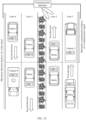
- FIG. 5 is a schematic diagram of another current ETC toll collection scenario.
- an RSU 1 is deployed on a lane 1
- an RSU 2 is deployed on a lane 2.
- a speed direction of a vehicle 1 on the lane 1 is a first direction
- a speed direction of a vehicle 2 on the lane 2 is a second direction.
- the RSU 1 performs an ETC transaction with an OBU 1 on the vehicle 1
- the RSU 2 performs an ETC transaction with an OBU 2 on the vehicle 2.
- the OBU 1 in FIG. 5 is used as an example.
- the OBU 1 may also enter a coverage area of the RSU 2 on the reverse lane, and the RSU 2 may also perform an ETC transaction with the OBU 1. Therefore, both the RSU 1 and the RSU 2 may perform toll collection on the OBU 1.
- embodiments of this application provide a communication method, a signal processing apparatus, and a communication apparatus, to improve working efficiency and performance of a sensing and communication integrated communication apparatus.
- FIG. 6 is a schematic flowchart of a communication method 200 according to an embodiment of this application. The method 200 may be applied to the system 100 shown in FIG. 2 .
- the method 200 may be performed by the communication apparatus 110 in the system 100 shown in FIG. 2 , or may be performed by the communication apparatus 110 under control of the signal processing apparatus 113 in the communication apparatus 110 shown in FIG. 3 .
- the method 200 is performed by the communication apparatus 110 in the system 100 shown in FIG. 2 , or may be performed by the communication apparatus 110 under control of the signal processing apparatus 113 in the communication apparatus 110 shown in FIG. 3 .
- the method 200 is performed by the communication apparatus 110 is used below for description.
- this embodiment of this application is not limited thereto.
- S210 Transmit a first radar transmit signal in a first frequency band by using a first transmit antenna array.
- S220 Receive a first echo signal of the first radar transmit signal in the first frequency band by using a first receive antenna array, where the first echo signal includes an echo signal corresponding to at least one first terminal.
- S230 Communicate with at least one second terminal in a second frequency band by using a second transmit antenna array and a second receive antenna array, where the first frequency band and the second frequency band do not overlap.
- the second frequency band may include a first sub-frequency band and a second sub-frequency band, and the first sub-frequency band and the second sub-frequency band do not overlap.
- S230 may include: receiving a first communication signal from the at least one second terminal in the first sub-frequency band by using the second receive antenna array; and/or transmitting a second communication signal to the at least one second terminal in the second sub-frequency band by using the second transmit antenna array.
- the first communication signal and the second communication signal may support a first communication protocol, that is, the first communication signal and the second communication signal may be understood as signals transmitted during communication by using the first communication protocol.
- the first communication protocol is an ETC communication protocol is only used as an example for description. However, it should be learned that the first communication protocol may be another communication protocol. This is not limited in embodiments of this application.
- the communication apparatus may be a sensing and communication integrated communication apparatus.
- the communication apparatus has a communication capability, that is, can receive and transmit communication signals (including the first communication signal and/or the second communication signal), to implement communication with a terminal, and has a sensing capability, that is, can receive and transmit radar signals (including the first radar transmit signal and/or the first echo signal).
- a communication capability that is, can receive and transmit communication signals (including the first communication signal and/or the second communication signal)
- radar signals including the first radar transmit signal and/or the first echo signal.
- High-precision ranging, speed measurement, angle measurement, and long-distance tracking of the terminal are implemented by using the foregoing communication method.
- the communication apparatus may implement sensing and communication functions in different frequency bands.
- the first communication signal and the second communication signal support the ETC communication protocol.
- the first frequency band may be a frequency band other than the first sub-frequency band and the second sub-frequency band in available frequency bands, and the first frequency band, the first sub-frequency band, and the second sub-frequency band do not overlap.
- a working frequency range of a radio communication device in a 5.8 G frequency band is 5725 MHz to 5850 MHz, and the communication apparatus performs ETC communication with a second terminal.
- FIG. 7 is a schematic diagram of signal frequency band distribution of a sensing and communication integrated communication apparatus.
- the foregoing frequency band distribution includes at least one of the following: the first sub-frequency band occupied by the first communication signal includes some or all frequencies in a frequency band 2 (5787.5 MHz to 5802.5 MHz), the second sub-frequency band occupied by the second communication signal includes some or all frequencies in a frequency band 4 (5827.5 MHz to 5842.5 MHz), and the first frequency band occupied by the radar signal (including the first radar signal and the first echo signal) includes some or all frequencies in a low frequency band 1 (5725 MHz to 5787.5 MHz), a middle frequency band 3 (5802.5 MHz to 5827.5 MHz) or a high frequency band 5 (5842.5 MHz to 5850 MHz).
- a bandwidth of the radar signal is wider than that of the communication signal.
- the radar signal adopts a mechanism of signal coherent accumulation, which determines that a coverage area of the radar signal is larger than that of the communication signal.
- the communication apparatus can not only transmit a narrow-bandwidth communication signal, but also transmit a highbandwidth radar signal with higher precision and a larger coverage area.
- an uplink signal has a specific frequency offset. Therefore, for this frequency offset, a specific guard frequency band needs to be added to a frequency band occupied by the uplink signal (that is, the first communication signal), to avoid mutual interference between the communication signal and the radar signal.
- a width of the guard frequency band may be 1.2 MHz.
- FIG. 8 is a schematic diagram of another signal frequency band distribution of a sensing and communication integrated communication apparatus.
- the frequency band distribution includes at least one of the following: the first sub-frequency band occupied by the first communication signal includes some or all frequencies in a frequency band 2 (5787.5 MHz to 5802.5 MHz), the second sub-frequency band occupied by the second communication signal includes some or all frequencies in a frequency band 4 (5827.5 MHz to 5842.5 MHz), and the first frequency band occupied by the radar signal (including the first radar signal and the first echo signal) includes some or all frequencies in a low frequency band 1 (5725 MHz to 5786.3 MHz), a middle frequency band 3 (5803.7 MHz to 5827.5 MHz) or a high frequency band 5 (5842.5 MHz to 5850 MHz).
- a frequency band shown in a shadow part in FIG. 8 is a guard frequency band.
- frequency band distribution of the radar signal and the communication signal shown in FIG. 7 and FIG. 8 is only an example, and this embodiment of this application is not limited thereto.
- the radar signal and the communication signal may alternatively use another frequency band distribution manner. This is not limited in embodiments of this application.
- the first transmit antenna array and the second transmit antenna array may be the same or different; and/or the first receive antenna array and the second receive antenna array may be the same or different. This is not limited in embodiments of this application.
- the first transmit antenna array and the second transmit antenna array are different, and the first receive antenna array and the second receive antenna array are different.
- the communication apparatus may include two independent transceiver antenna arrays.
- the communication apparatus may receive and transmit communication signals (for example, receive an uplink first communication signal and transmit a downlink second communication signal) by using one transceiver antenna array, and receive and transmit radar signals (for example, transmit a first radar signal and receive a first echo signal) by using another transceiver antenna array.
- downlink is a transmission direction from the communication apparatus to the terminal
- uplink is a transmission direction from the terminal to the communication apparatus.
- first transmit antenna array and the second transmit antenna array are the same, and the first receive antenna array and the second receive antenna array are different.
- the communication apparatus may include one transmit antenna array and two receive antenna arrays.
- the communication apparatus may transmit a radar signal (for example, a first radar signal) and a downlink communication signal (for example, a second communication signal) by multiplexing the transmit antenna array in a frequency division manner, and respectively receive an echo signal (for example, a first echo signal) and an uplink communication signal (for example, a first communication signal) by using the two receive antenna arrays.
- a radar signal for example, a first radar signal
- a downlink communication signal for example, a second communication signal
- an echo signal for example, a first echo signal
- an uplink communication signal for example, a first communication signal
- first transmit antenna array and the second transmit antenna array are different, and the first receive antenna array and the second receive antenna array are the same.
- the communication apparatus may include one receive antenna array and two transmit antenna arrays.
- the communication apparatus may receive an echo signal (for example, a first echo signal) and an uplink communication signal (for example, a first communication signal) by multiplexing the receive antenna array in a frequency division manner, and respectively transmit a radar signal (for example, a first radar signal) and a downlink communication signal (for example, a second communication signal) by using the two transmit antenna array s.
- an echo signal for example, a first echo signal
- an uplink communication signal for example, a first communication signal
- a radar signal for example, a first radar signal
- a downlink communication signal for example, a second communication signal
- first transmit antenna array and the second transmit antenna array are the same, and the first receive antenna and the second receive antenna array are the same.
- the communication apparatus may include only one transceiver antenna array, and the communication apparatus may receive and transmit a communication signal and a radar signal by multiplexing the transceiver antenna array in a frequency division manner.
- the communication apparatus implements radar signal receiving and transmitting (for example, transmitting a first radar signal and receiving a first echo signal) and communication signal receiving and transmitting (for example, receiving an uplink first communication signal and transmitting a downlink second communication signal) by multiplexing one transceiver antenna array in a frequency division manner, so that costs and overheads of the communication apparatus can be reduced.
- radar signal receiving and transmitting for example, transmitting a first radar signal and receiving a first echo signal
- communication signal receiving and transmitting for example, receiving an uplink first communication signal and transmitting a downlink second communication signal
- the communication apparatus includes one transmit antenna array and one receive antenna array, the transmit antenna array includes a plurality of transmit antennas, and the receive antenna array includes a plurality of receive antennas.
- S230 may include: The communication apparatus receives a first communication signal from the at least one second terminal in the first sub-frequency band by using the plurality of receive antennas; and/or transmits a second communication signal to the at least one second terminal in the second sub-frequency band by using the plurality of transmit antennas.
- the communication apparatus may transmit the first radar signal by multiplexing at least two transmit antennas in the plurality of transmit antennas; and/or in S220, the communication apparatus may receive the first echo signal by multiplexing at least two receive antennas in the plurality of receive antennas.
- the communication apparatus includes a transmit antenna array and a receive antenna array, the transmit antenna array includes four Tx antennas, the receive antenna array includes four Rx antennas, and the four Tx antennas and the four Rx antennas are in a one-row and four-column layout.
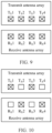
- FIG. 9 is a schematic diagram of an antenna array according to an embodiment of this application. As shown by " ⁇ " in FIG. 9 , the communication apparatus may transmit the second communication signal by using T X 1 to Tx4 (that is, four T X antennas), and receive the first communication signal by using R X 1 to Rx4 (that is, four R X antennas). As shown by " ⁇ " in FIG.
- the communication apparatus may transmit the first radar signal by multiplexing T X 1 to Tx4 (that is, four Tx antennas) in a frequency division manner, and receive the first echo signal by multiplexing R X 1 to R X 4 (that is, four R X antennas).
- the communication apparatus includes a transmit antenna array and a receive antenna array, the transmit antenna array includes four Tx antennas, the receive antenna array includes four Rx antennas, and the four Tx antennas and the four Rx antennas are in a one-row and four-column layout.
- FIG. 10 is a schematic diagram of another antenna array according to an embodiment of this application. As shown by " ⁇ " in FIG. 10 , the communication apparatus may transmit the second communication signal by using T X 1 to Tx4 (that is, four T X antennas), and receive the first communication signal by using R X 1 to Rx4 (that is, four R X antennas). As shown by " ⁇ " in FIG.
- the communication apparatus may transmit the first radar signal by multiplexing T X 1 and Tx3 (that is, two Tx antennas) in a frequency division manner, and receive the first echo signal by multiplexing Rx2 and Rx4 (that is, two R X antennas).
- two Tx antennas and two Rx antennas used for receiving and transmitting a radar signal in FIG. 10 may be equivalent to one T X antenna and four Rx antennas. Therefore, an aperture of a receive antenna array may be extended from two physical receive antennas to four virtual receive antennas, that is, a quantity of used antennas can be reduced without reducing resolution of a horizontal angle. This helps reduce complexity of signal processing.
- the communication apparatus may further improve resolution of a pitch angle of the radar signal, or jointly improve the resolution of the horizontal angle and the pitch angle of the radar signal. Details are not described herein in this embodiment of this application again.
- the at least one first terminal may include the at least one second terminal.
- the at least one first terminal and the at least one second terminal are different. This is not limited in embodiments of this application.
- the at least one first terminal may include the at least one second terminal
- the at least one second terminal may be determined from the at least one first terminal.
- the communication apparatus may determine the at least one second terminal from the at least one first terminal.
- the at least one second terminal may include one or more first terminals whose first distance from the first receive antenna array is less than or equal to a first distance threshold and/or whose speed direction is a first direction in the at least one first terminal.
- various distances in this application may be mutually converted in some cases.
- distances of the transmit antenna array, distances of the receive antenna array, or distances between the transmit antenna array and receive antenna array are preset. In this way, other distances may be deduced, calculated, or determined based on one distance, that is, there is a specific conversion relationship between these distances. Therefore, the communication apparatus may obtain another distance based on one of the distances and a relative location relationship between the antenna arrays. In this embodiment of this application, only one distance is used as an example for description. However, this embodiment of this application is not limited thereto.
- the first distance threshold may represent a maximum communication distance of a communication signal. That is, when the first distance of the first terminal is less than or equal to the first distance threshold, the first terminal is within the maximum communication distance of the communication signal, that is, the first terminal can communicate with the communication apparatus.
- the first distance threshold may be less than a second distance threshold, and the second distance threshold may represent a maximum detection distance of the radar signal. That is, when the first distance of the first terminal is greater than the first distance threshold but less than the second distance threshold, the first terminal may be detected by using a radar signal, but cannot communicate with the communication apparatus.
- the first distance threshold and/or the second distance threshold may be parameters preconfigured for the communication apparatus.
- the coverage area of the communication signal is a sphere that uses the communication apparatus (or the second transmit antenna array or the second receive antenna array) as a circle center and uses a maximum communication distance (for example, the first distance threshold) of the communication signal as a radius; and/or the coverage area of the radar signal is a sphere that uses the communication apparatus (or the first transmit antenna array or the first receive antenna array) as a circle center and uses a maximum detection distance (for example, the second distance threshold) of the radar signal as a radius.
- the communication apparatus may determine the at least one second terminal from the at least one first terminal in a plurality of manners. This is not limited in embodiments of this application.
- the communication apparatus may transmit an activation signal (that is, a communication signal) through broadcasting; receive an answer signal corresponding to the activation signal; and determine at least one first terminal corresponding to the received answer signal as the at least one second terminal.
- the at least one second terminal may include one or more first terminals that are in the at least one first terminal and that are successfully activated by the activation signal of the communication apparatus and that transmit an answer signal corresponding to the activation signal to the communication apparatus.
- the communication apparatus determines, by broadcasting the activation signal, the at least one activated second terminal, and only needs to simply receive and transmit a signal, without processing the signal, so that processing complexity of the communication apparatus can be reduced.
- the communication apparatus may determine the at least one second terminal from the at least one first terminal based on the first echo signal.
- the at least one second terminal is determined from the at least one first terminal based on the first echo signal.
- the communication apparatus may determine, based on the first echo signal, a first distance and/or a speed direction between a first terminal in the at least one first terminal and the first receive antenna array; and determine the at least one second terminal from the at least one first terminal based on the first distance and/or the speed direction between the first terminal in the at least one first terminal and the first receive antenna array.
- first distance between the first terminal in the at least one first terminal and the first receive antenna array may be indicated by using first distance information; and/or the speed direction of the first terminal in the at least one first terminal may be indicated by using speed information.
- the communication apparatus may determine the first distance information and/or the speed information based on the first echo signal, and determine the at least one second terminal from the at least one first terminal based on the first distance information and/or the speed information.
- the first radar signal is a frequency modulated continuous wave (frequency modulated continuous wave, FMCW).
- the communication apparatus may perform first-dimensional fast Fourier transform (fast Fourier transformation, FFT) on a demodulated signal of the first echo signal to obtain a distance spectrum (that is, first distance information), and obtain a first distance between each first terminal of the at least one first terminal and the first receive antenna array based on the distance spectrum.
- FFT fast Fourier transformation
- the first radar transmit signal is an FMCW.
- the communication apparatus may perform second-dimensional FFT on the demodulated signal of the first echo signal to obtain a Doppler velocity spectrum (that is, speed information), and obtain a speed of each of the at least one first terminal based on the Doppler velocity spectrum.
- a Doppler velocity spectrum that is, speed information
- speed information a speed of each of the at least one first terminal based on the Doppler velocity spectrum.
- a manner of obtaining the speed of the first terminal is not specifically limited in this embodiment of this application.
- a speed direction of each first terminal may be obtained by obtaining a speed of each first terminal of the at least one first terminal.
- the speed direction in this embodiment of this application mainly includes a traveling direction towards the communication apparatus (that is, the first direction) or a traveling direction away from the communication apparatus.
- the communication apparatus can communicate with the at least one second terminal more accurately, thereby improving a communication success rate and communication efficiency.
- FIG. 11 is a schematic diagram of another application scenario according to an embodiment of this application.
- the communication apparatus may track an OBU 1 to an OBU 6 in a coverage area of a radar signal in real time by using the radar signal, and measure a first distance between each OBU and the communication apparatus based on an echo signal.
- the communication apparatus detects that the first distances to the OBU 1, the OBU 2, and the OBU 3 each are less than or equal to a maximum communication distance of a communication signal
- the communication apparatus determines that the OBU 1, the OBU 2, and the OBU 3 are within a coverage area of the communication signal, and then communicates with the OBU 1 and the OBU 2. This can improve a communication success rate.
- FIG. 12 is a schematic diagram of still another application scenario according to an embodiment of this application.
- the communication apparatus may track an OBU 1 to an OBU 6 in real time in a coverage area of a radar signal by using the radar signal, and measure a first distance between each OBU and the communication apparatus and a speed direction of each OBU based on an echo signal.
- the communication apparatus detects that first distances to the OBU 1 and the OBU 2 each are less than or equal to a maximum communication distance of a communication signal and speed directions are the first direction
- the communication apparatus determines that the OBU 1 and the OBU 2 are in a coverage area of the communication signal and that traveling directions are correct, and then communicates with the OBU 1 and the OBU 2. This can avoid an error of repeated transaction on a reverse lane.
- the communication apparatus may receive the first communication signal from the at least one second terminal in the first sub-frequency band by using the second receive antenna array, and transmit the second communication signal to the at least one second terminal in the second sub-frequency band by using the second transmit antenna array.
- the communication apparatus may transmit the second communication signal to the at least one second terminal in the second sub-frequency band by using the second transmit antenna array in a plurality of manners. This is not limited in embodiments of this application.
- the communication apparatus may transmit the second communication signal to the at least one second terminal in the second frequency band based on the first communication signal by using the second transmit antenna array.
- the second communication signal is transmitted after beamforming is performed, by using first angle information, on a signal transmitted by the second transmit antenna array, where the first angle information is obtained based on a first communication signal from the at least one second terminal, and the first angle information is used to indicate at least one of a horizontal angle or a pitch angle of the at least one second terminal relative to the second transmit antenna array.
- the communication apparatus may obtain the first angle information based on the first communication signal from the at least one second terminal, perform, based on the first angle information, beamforming on a downlink communication signal transmitted by the second transmit antenna array, and transmit, to each second terminal of the at least one second terminal, a beamformed second communication signal corresponding to each second terminal.
- the communication apparatus performs a separate operation on the first communication signal of each second terminal, to obtain an angle (including a horizontal angle and/or a pitch angle) of each second terminal relative to the second transmit antenna array. Similarly, the communication apparatus performs, based on the angle of each second terminal relative to the second transmit antenna array, beamforming on a signal transmitted by the second transmit antenna array, and separately transmits, to each second terminal, a beamformed second communication signal corresponding to each second terminal.
- angles in this embodiment of this application, for example, an angle of the terminal relative to the first transmit antenna array, an angle of the terminal relative to the second transmit antenna array, an angle of the terminal relative to the first receive antenna array, an angle of the terminal relative to the second receive antenna array, or an angle of the terminal relative to the communication apparatus, may be mutually converted in some cases.
- an angle relationship of each transmit antenna array, an angle relationship of each receive antenna array, or an angle relationship between each transmit antenna array and each receive antenna array is preset. In this way, another angle may be deduced, calculated, or determined based on one angle, that is, there is a conversion relationship between these angles. Therefore, the communication apparatus may obtain another angle based on one of the angles and a relative angle relationship between the antenna arrays.
- only one angle is used as an example for description. However, this embodiment of this application is not limited thereto.
- the first angle information may include a horizontal angle and/or a pitch angle of the at least one second terminal relative to the second transmit antenna array; or the first angle information may include a horizontal angle and/or a pitch angle of the at least one second terminal relative to the second receive antenna array; or the first angle information may include a horizontal angle and/or a pitch angle of the at least one second terminal relative to the communication apparatus.
- the communication apparatus may perform first-dimensional FFT on a demodulated signal of the first communication signal of the second terminal, to obtain a horizontal angle of the second terminal relative to the second receive antenna array; and/or perform second-dimensional FFT on the demodulated signal of the first communication signal of the second terminal, to obtain a pitch angle of the second terminal relative to the second receive antenna array.
- first-dimensional FFT on a demodulated signal of the first communication signal of the second terminal
- second-dimensional FFT on the demodulated signal of the first communication signal of the second terminal, to obtain a pitch angle of the second terminal relative to the second receive antenna array.
- FIG. 13 is a schematic diagram of communication between the communication apparatus and a second terminal.
- the at least one second terminal includes a terminal 1 and a terminal 2 is used as an example.
- the communication apparatus may determine, based on a first communication signal of the terminal 1, a horizontal angle ⁇ 1 and a pitch angle ⁇ 1 of the terminal 1 relative to the second receive antenna array.
- the communication apparatus may determine, based on the first communication signal of the terminal 2, a horizontal angle ⁇ 2 and a pitch angle ⁇ 2 of the terminal 2 relative to the second receive antenna array.
- the communication apparatus may determine, based on the horizontal angle ⁇ 1 and the pitch angle ⁇ 1 , coordinates 1 of the terminal 1 relative to a coordinate origin 1 corresponding to the second receive antenna array, for example, three-dimensional coordinates 1-1; determine, based on the three-dimensional coordinates 1-1 and a predefined first mapping relationship, three-dimensional coordinates 2-1 of the terminal 1 relative to a coordinate origin 2 corresponding to the second transmit antenna array, where the first mapping relationship is used to represent three-dimensional coordinate variations of the terminal relative to the coordinate origin 1 and the coordinate origin 2; determine, based on the three-dimensional coordinates 2-1, a horizontal angle ⁇ 3 and a pitch angle ⁇ 3 of the terminal 1 relative to the second transmit antenna array; and transmit a second communication signal corresponding to the terminal 1 to the terminal 1 after performing, based on the horizontal angle ⁇ 3 and the pitch angle ⁇ 3 , beamforming on a signal transmitted by the second transmit antenna array.
- the communication apparatus may determine, based on the horizontal angle ⁇ 2 and the pitch angle ⁇ 2 , coordinates 2 of the terminal 2 relative to the coordinate origin 1, for example, three-dimensional coordinates 1-2; and determine, based on the three-dimensional coordinates 1-2 and the first mapping relationship, three-dimensional coordinates 2-2 of the terminal 2 relative to the coordinate origin 2; determine, based on the three-dimensional coordinates 2-2, a horizontal angle ⁇ 4 and a pitch angle ⁇ 4 of the terminal 2 relative to the second transmit antenna array; and transmit a second communication signal corresponding to the terminal 2 to the terminal 2 after performing, based on the horizontal angle ⁇ 4 and the pitch angle ⁇ 4 , beamforming on a signal transmitted by the second transmit antenna array.
- the communication apparatus may determine, based on the horizontal angle ⁇ 1 , the pitch angle ⁇ 1 , and a predefined second mapping relationship, the horizontal angle ⁇ 3 and the pitch angle ⁇ 3 of the terminal 1 relative to the second transmit antenna array, where the second mapping relationship is used to indicate angle variations of the terminal relative to the coordinate origin 1 and the coordinate origin 2; and transmit a second communication signal corresponding to the terminal 1 to the terminal 1 after performing, based on the horizontal angle ⁇ 3 and the pitch angle ⁇ 3 , beamforming on a signal transmitted by the second transmit antenna array.
- the communication apparatus may determine, based on the horizontal angle ⁇ 2 , the pitch angle ⁇ 2 , and the second mapping relationship, the horizontal angle ⁇ 4 and the pitch angle ⁇ 4 of the terminal 2 relative to the second transmit antenna array; and transmit a second communication signal corresponding to the terminal 2 to the terminal 2 after performing, based on the horizontal angle ⁇ 4 and the pitch angle ⁇ 4 , beamforming on a signal transmitted by the second transmit antenna array.
- the communication apparatus does not need to obtain coordinates (for example, the three-dimensional coordinates 1-1 and the three-dimensional coordinates 2-1, and/or the three-dimensional coordinates 1-2 and the three-dimensional coordinates 2-2) of each terminal, that is, the coordinates of each terminal may not be reflected as an intermediate result.
- an angle (including a horizontal angle and/or a pitch angle) of the second terminal relative to the second receive antenna array may be equivalently converted into an angle of the second terminal relative to the second transmit antenna array.
- the communication apparatus may further perform other equivalent conversion on the angle of the second terminal relative to the second receive antenna array by using a method similar to that described in FIG. 13 . Details are not described again in this embodiment of this application again.
- the communication apparatus may accurately guide beamforming of a downlink communication signal as much as possible by using a sensing capability of an uplink first communication signal, thereby improving work efficiency and performance of the sensing and communication integrated communication apparatus.
- the communication apparatus may transmit the second communication signal to at least one third terminal in the second frequency band based on the first communication signal and the second echo signal by using the second transmit antenna array, where the at least one second terminal includes the at least one third terminal, and the second echo signal includes an echo signal corresponding to the at least one second terminal.
- the communication apparatus may obtain the second echo signal in a plurality of manners. This is not limited in embodiments of this application.
- the communication apparatus may obtain the second echo signal from the first echo signal.
- the first echo signal includes the second echo signal.
- the communication apparatus may transmit a second radar signal in the first frequency band by using the first transmit antenna array; and receive the second echo signal of the second radar signal in the first frequency band by using the first receive antenna array.
- the second radar signal may be a radar signal transmitted by the communication apparatus after the first radar signal.
- the second communication signal is transmitted after beamforming is performed, by using second angle information and third angle information, on the signal transmitted by the second transmit antenna array.
- the second angle information is used to indicate a pitch angle of the at least one third terminal relative to the second transmit antenna array
- the third angle information is used to indicate a horizontal angle of the at least one third terminal relative to the first transmit antenna array
- the second angle information is obtained based on the first communication signal from the at least one third terminal
- the third angle information is obtained based on the second echo signal.
- the communication apparatus may obtain the second angle information and the third angle information based on the first communication signal from the at least one third terminal and the second echo signal; and perform, based on the second angle information and the third angle information, beamforming on the downlink communication signal transmitted by the second transmit antenna array, and transmit, to each third terminal of the at least one third terminal, a beamformed second communication signal corresponding to each third terminal.
- the third angle information includes the horizontal angle of the at least one third terminal relative to the first transmit antenna array.
- the communication apparatus may perform third-dimensional FFT on a demodulated signal of the second echo signal, to obtain the third angle information.
- a manner of obtaining the third angle information is not specifically limited in this embodiment of this application.
- replacing the uplink first communication signal with the second radar signal to sense the horizontal angle of the at least one third terminal can optimize beamforming precision of the downlink communication signal, thereby improving work efficiency and performance of the sensing and communication integrated communication apparatus.
- the second echo signal obtained by the communication apparatus based on the second radar signal transmitted after the first radar signal (that is, based on the second echo signal obtained in the foregoing second manner) has better real-time performance, and can be used to obtain third angle information with high precision, which can be used to further optimize beamforming precision of a downlink communication signal, thereby improving work efficiency and performance of the sensing and communication integrated communication apparatus.
- the at least one third terminal is determined from the at least one second terminal.
- the communication apparatus may determine the at least one third terminal from the at least one second terminal.
- the at least one third terminal may include one or more second terminals whose distance difference is less than or equal to a third distance threshold in the at least one second terminal, where the distance difference of the second terminal indicates a difference between a second distance between the second terminal and the first receive antenna array and a third distance between the second terminal and the second receive antenna array, where the second distance between the at least one second terminal and the first receive antenna array is obtained based on the second echo signal, and the third distance between the at least one second terminal and the second receive antenna array is determined based on the first communication signal of the at least one second terminal.
- the second distance is indicated by using second distance information
- the third distance is indicated by using third distance information.
- the communication apparatus may determine the second distance information based on the second echo signal; determine the second distance between the at least one second terminal and the first receive antenna array based on the second distance information; determine the third distance information of the at least one second terminal based on the first communication signal from the at least one second terminal; determine the third distance between the at least one second terminal and the second receive antenna array based on the third distance information; and determine the second distance between the at least one second terminal and the first receive antenna array and the third distance between the at least one second terminal and the second receive antenna array based on the second distance information, and determine the at least one third terminal from the at least one second terminal.
- the communication apparatus may determine, based on the first communication signal of the second terminal, a horizontal angle and a pitch angle (the third distance information) of the second terminal relative to the second receive antenna array, and determine, based on the horizontal angle and the pitch angle, the third distance of the second terminal relative to the second receive antenna array.
- a horizontal angle and a pitch angle the third distance information
- the third distance of the second terminal relative to the second receive antenna array the third distance of the second terminal relative to the second receive antenna array.
- the third distance threshold may be understood as an error threshold between the second distance determined based on the radar signal and the third distance determined based on the communication signal. That is, when the difference is less than or equal to the third distance threshold, the communication apparatus may determine that the distances of the second terminals that are determined based on the second echo signal and the first communication signal are approximately consistent. Alternatively, when the difference is greater than the third distance threshold, the communication apparatus may determine that the distances of the second terminal determined by using the second echo signal and the first communication signal are inconsistent.
- the third distance threshold may be a parameter preconfigured for the communication apparatus.
- the communication apparatus excludes, from the at least one second terminal, a second terminal whose distance determined based on a radar signal and a communication signal is inconsistent, so as to avoid a case in which a second communication signal corresponding to the second terminal cannot be accurately transmitted to the second terminal due to incorrect distance determining of the second terminal, thereby improving beamforming precision of a downlink communication signal, and improving work efficiency and performance of the sensing and communication integrated communication apparatus.
- the communication apparatus may transmit the second communication signal to the at least one second terminal in the second frequency band based on the second echo signal by using the second transmit antenna array, where the second echo signal includes an echo signal corresponding to the at least one second terminal.
- the second communication signal is transmitted after beamforming is performed, by using fourth angle information, on a signal transmitted by the second transmit antenna array, where the fourth angle information is obtained based on the second echo signal, and the fourth angle information is used to indicate at least one of a horizontal angle or a pitch angle of the at least one second terminal relative to the second transmit antenna array.
- the communication apparatus may obtain the fourth angle information based on the second echo signal, perform, based on the fourth angle information, beamforming on the downlink communication signal transmitted by the second transmit antenna array, and transmit, to each second terminal of the at least one second terminal, a beamformed second communication signal corresponding to each second terminal.
- the fourth angle information includes the horizontal angle and/or the pitch angle of the at least one second terminal relative to the second receive antenna array
- the communication apparatus may perform third-dimensional FFT on a demodulated signal of the second echo signal, to obtain the horizontal angle of the at least one second terminal relative to the second receive antenna array; and/or perform fourth-dimensional FFT on the demodulated signal of the second echo signal, to obtain a pitch angle of the at least one second terminal relative to the second receive antenna array.
- the communication apparatus can communicate with second terminals on a plurality of lanes as accurately as possible by using any one of the foregoing manners 1 to 3.
- only one sensing and communication integrated communication apparatus provided in this embodiment of this application needs to be installed on the plurality of lanes, so that multi-lane coverage and multi-lane vehicle sensing can be implemented, thereby reducing costs and maintenance amounts.
- the method 200 may further include: The communication apparatus inspects, based on the first echo signal and the first communication signal, a vehicle violating traffic rules in the at least one second terminal.
- the vehicle violating traffic rules include a second terminal that is in the at least one second terminal and whose first vehicle model fails to match a second vehicle model, the first vehicle model represents a real vehicle model of the second terminal, and the second vehicle model represents a vehicle model reported by the second terminal.
- the first vehicle model may be indicated by using first vehicle model information
- the second vehicle model may be indicated by using second vehicle model information
- the first vehicle model information is obtained based on a first echo signal
- the second vehicle model information is indicated by using a first communication signal from the second terminal.
- the communication apparatus may determine the first vehicle model information of the second terminal based on the first echo signal, where the first vehicle model information is used to indicate the first vehicle model of the second terminal; obtain the second vehicle model information indicated by the first communication signal from the second terminal, where the second vehicle model information is used to indicate the second vehicle model of the second terminal; and match the first vehicle model with the second vehicle model; and if the matching fails, a vehicle in which the second terminal is located is a vehicle violating traffic rules.
- vehicle types in this embodiment of this application may include a large vehicle, a medium vehicle, or a small vehicle.
- the first radar signal is a frequency modulated continuous wave FMCW.
- the communication apparatus may perform first-dimensional FFT on a demodulated signal of the first echo signal to obtain a distance spectrum, and determine the first vehicle model of the second terminal based on the distance spectrum.
- the communication apparatus may determine a vehicle length of the second terminal based on the distance spectrum.
- the vehicle length of the second terminal may be a distance difference between the first receive antenna array and a vehicle head and a vehicle rear of the vehicle in which the second terminal is located.
- the communication apparatus may assist a traffic management department in inspecting a vehicle violating traffic rules by using an uplink first communication signal and a first echo signal.
- the communication apparatus may give an alarm, prompt, and/or further track the at least one second target terminal.
- the at least one second terminal includes the at least one second target terminal. This is not limited in embodiments of this application.
- the communication apparatus may determine location information of the at least one second target terminal based on a first communication signal from the at least one second target terminal, and transmit the location information of the at least one second target terminal to a camera apparatus, where the location information of the at least one second target terminal is used to position the at least one second target terminal.
- the communication apparatus may determine first angle information of the at least one second target terminal based on the first communication signal from the at least one second target terminal, where the first angle information is used to indicate a horizontal angle and/or a pitch angle between the second target terminal and the second transmit antenna array; and determine the location information of the at least one second target terminal based on the first angle information of the at least one second target terminal.
- the camera apparatus may capture an image of the at least one second target terminal in real time based on the location information of the at least one second target terminal, and perform tracking processing on the at least one second target terminal based on the image of the at least one second target terminal.
- the communication apparatus may position the second target terminal in real time based on a first communication signal from the second target terminal on the vehicle violating traffic rules, and assist the camera apparatus in further tracking based on the positioning.
- the communication apparatus may be the communication apparatus in the embodiment of the foregoing method 200, and can perform the method implemented by the communication apparatus in the foregoing method 200.
- the communication apparatus includes corresponding hardware structures and/or software modules for performing the functions.
- this application can be implemented in a form of hardware or a combination of hardware and computer software. Whether a function is performed by hardware or hardware driven by computer software depends on particular applications and design constraints of the technical solution. A person skilled in the art may use different methods to implement the described functions for each particular application scenario, but it should not be considered that the implementation goes beyond the scope of this application.
- the communication apparatus may be divided into function modules based on the method examples.
- each function module may be obtained through division based on each corresponding function, or two or more functions may be integrated into one processing module.
- the integrated module may be implemented in a form of hardware. It should be noted that, in embodiments, division into the modules is an example, is merely logical function division, and may be other division during actual implementation.
- FIG. 14 is a possible schematic composition diagram of the communication apparatus in the foregoing embodiments.
- the apparatus 300 may include a transceiver unit 310 and a processing unit 320.
- the processing unit 320 may control the transceiver unit 310 to implement the method performed by the communication apparatus in the foregoing method 200 embodiment, and/or another process of the technology described in this specification.
- the transceiver unit 310 is a functional representation of the transmit antenna array and/or the receive antenna array in the foregoing embodiments of the method 200.
- the apparatus 300 may include a processing unit, a storage unit, and a communication unit.
- the processing unit may be configured to control and manage an action of the apparatus 300, for example, may be configured to support the apparatus 300 in performing steps performed by the foregoing units.
- the storage unit may be configured to support the apparatus 300 in storing program code, data, and the like.
- the communication unit may be configured to support the apparatus 300 in communicating with another device.
- the processing unit may be a processor or a controller.
- the processing apparatus may implement or execute various example logical blocks, modules, and circuits described with reference to content disclosed in this application.
- the processor may be a combination of processors implementing a computing function, for example, a combination of one or more microprocessors, or a combination of a digital signal processor (digital signal processor, DSP) and a microprocessor.
- the storage unit may be a memory.
- the communication unit may be specifically a device that interacts with another electronic device, like a radio frequency circuit, a Bluetooth chip, or a Wi-Fi chip.
- the signal processing apparatus in this embodiment of this application may be an apparatus 400 with a structure shown in FIG. 15 .
- the apparatus 400 includes at least one processor 410 and at least one communications interface 420.
- the processor 410 and the communications interface 420 communicate with each other over an internal connection path.
- a related function implemented by the processing unit 320 in FIG. 14 may be implemented by the processor 410, and a related function implemented by the transceiver unit 310 may be implemented by the processor 410 by controlling a first transmit antenna array and a first receive antenna array by using the communications interface 420.
- a related function implemented by the transceiver unit 310 may be implemented by the processor 410 by controlling the first transmit antenna array and the first receive antenna array, and a second transmit antenna array and/or a second receive antenna array by using the communications interface 420.
- the apparatus 400 may further include a memory 430.
- the processor 410, the communications interface 420, and the memory 430 communicate with each other over an internal connection path.
- a related function implemented by the storage unit in FIG. 14 may be implemented by the memory 430.
- An embodiment of this application further provides an apparatus.
- the apparatus may be specifically a chip, a component, or a module.
- the apparatus may include a processor and a memory that are connected.
- the memory is configured to store computer-executable instructions.
- the processor may execute the computer-executable instructions stored in the memory, to enable the chip to perform the communication method in the foregoing method embodiments.
- FIG. 16 is a schematic diagram of a structure of a chip 500.
- the chip 500 includes one or more processors 510 and an interface circuit 520.
- the chip 500 may further include a bus 530.
- the processor 510 may be an integrated circuit chip and has a signal processing capability. In an implementation process, steps of the method may be completed by using an integrated logic circuit of hardware in the processor 510 or instructions in a form of software.
- the processor 510 may be a general-purpose processor, a digital signal processor (digital signal processor, DSP), an application-specific integrated circuit (application-specific integrated circuit, ASIC), a field-programmable gate array (field-programmable gate array, FPGA), another programmable logic device, a discrete gate or a transistor logic device, or a discrete hardware component.
- the processor 510 may implement or perform the methods and steps that are disclosed in embodiments of this application.
- the general-purpose processor may be a microprocessor, or the processor may be any conventional processor or the like.
- the interface circuit 520 may be configured to transmit a radar signal and/or a communication signal; and/or receive a radar signal and/or a communication signal.
- the interface circuit may be one or more interface circuits.
- the processor 510 controls, by using the interface circuit, a second receive antenna array to receive a communication signal from a terminal, and controls a second transmit antenna array to transmit a communication signal to the terminal.
- a second receive antenna array to receive a communication signal from a terminal
- a second transmit antenna array to transmit a communication signal to the terminal.
- the communication apparatus includes the second transmit antenna array and the second receive antenna array.
- the processor 510 controls, by using the interface circuit, the second transmit antenna array to transmit the radar signal, and controls the second receive antenna array to receive an echo signal of the radar signal.
- the communication apparatus includes the second transmit antenna array, the second receive antenna array, and a first transmit antenna array.
- the processor 510 controls, by using the interface circuit, the first transmit antenna array to transmit the radar signal, and controls the second receive antenna array to receive the echo signal of the radar signal.
- the communication apparatus includes the second transmit antenna array, the second receive antenna array, and a first receive antenna array.
- the processor 510 controls, by using the interface circuit, the second transmit antenna array to transmit the radar signal, and controls the first receive antenna array to receive the echo signal of the radar signal.
- the communication apparatus includes the second transmit antenna array, the second receive antenna array, the first transmit antenna array, and the first receive antenna array.
- the processor 510 controls, by using the interface circuit, the first transmit antenna array to transmit the radar signal, and controls the first receive antenna array to receive the echo signal of the radar signal.
- the chip further includes a memory.
- the memory may include a read-only memory (Read Only Memory, ROM) and/or a random access memory (Random Access Memory, RAM), and provides operation instructions and data for the processor.
- a part of the memory may further include a non-volatile random access memory (non-volatile random access memory, NVRAM).
- the memory stores an executable software module or a data structure
- the processor may perform a corresponding operation by invoking operation instructions (the operation instructions may be stored in an operating system) stored in the memory.
- the chip may be used in the communication apparatus in embodiments of this application.
- the interface circuit 520 may be configured to output an execution result of the processor 510.
- functions corresponding to each of the processor 510 and the interface circuit 520 may be implemented by using a hardware design, may be implemented by using a software design, or may be implemented by combining software and hardware. This is not limited herein.
- the communication apparatus may be a road side unit (RSU).
- the RSU may include the apparatus 400 in FIG. 15 or the chip 500 in FIG. 16 , a second transmit antenna array, and a second receive antenna array.
- the communication apparatus may further include a first transmit antenna array and/or a first receive antenna array.
- FIG. 17 is a schematic block diagram of a communication apparatus 600 according to an embodiment of this application.
- the apparatus 600 may include a processor 610, a communication interface 620, a second transmit antenna array 630, and a second receive antenna array 640.
- the processor 610, the communication interface 620, the second transmit antenna array 630, and the second receive antenna array 640 are coupled.
- the processor 610 is configured to control, by using the communication interface 620, the second transmit antenna array 630 and the second receive antenna array 640 to perform the communication method in the embodiment of the method 200.
- the communication interface 620 may be one or more communication interfaces.
- the second transmit antenna array 630 may include a plurality of transmit antennas
- the second receive antenna array 640 may include a plurality of receive antennas.
- the processor 610 is configured to control the plurality of transmit antennas and the plurality of receive antennas to receive and transmit communication signals, and/or control one or more of the plurality of transmit antennas and one or more of the plurality of receive antennas to receive and transmit radar signals. Further, the communication signal and the radar signal occupy different frequency bands.
- the apparatus 600 may further include a first transmit antenna array 650 and/or a first receive antenna array 660.
- the processor 610 is configured to control, by using the communication interface 620, the second transmit antenna array 630, the second receive antenna array 640, the first transmit antenna array 650, and/or the first receive antenna array 660 to perform the communication method in the embodiment of the method 200.
- the processor 610 is configured to control the second transmit antenna array 630 and the second receive antenna array 640 to receive and transmit a communication signal; and/or control the first transmit antenna array 650 and the first receive antenna array 660 to receive and transmit a radar signal. Further, the communication signal and the radar signal occupy different frequency bands.
- the processor 610 is configured to control the second transmit antenna array 630 and the second receive antenna array 640 to receive and transmit a communication signal; and/or control the second transmit antenna array 630 and the first receive antenna array 660 to receive and transmit a radar signal. Further, the communication signal and the radar signal occupy different frequency bands.
- the processor 610 is configured to control the second transmit antenna array 630 and the second receive antenna array 640 to receive and transmit a communication signal; and/or control the first transmit antenna array 650 and the second receive antenna array 640 to receive and transmit a radar signal. Further, the communication signal and the radar signal occupy different frequency bands.
- the processor 610 may be the processor 410 in FIG. 15 or the processor 510 in FIG. 16 . This is not limited in embodiments of this application.
- the apparatus 600 may further include a memory 670, and the memory 670 may be the memory 430 in FIG. 15 or the memory in FIG. 16 . This is not limited in embodiments of this application.
- An embodiment of this application further provides a computer storage medium.
- the computer storage medium stores computer instructions.
- the computer instructions When the computer instructions are run on an electronic device, the electronic device is enabled to perform the related method steps, to implement the communication method in the foregoing embodiments.
- An embodiment of this application further provides a computer program product.
- the computer program product runs on a computer, the computer is enabled to perform the foregoing related method steps, to implement the communication method in the foregoing embodiments.
- the signal processing apparatus, the communication apparatus, the computer storage medium, the computer program product, or the chip provided in embodiments of this application are all configured to perform the corresponding method provided above. Therefore, for beneficial effects that can be achieved by the signal processing apparatus, the communication apparatus, the computer storage medium, the computer program product, or the chip, refer to beneficial effects in the corresponding method provided above. Details are not described herein again.
- sequence numbers of the foregoing processes do not mean execution sequences.
- the execution sequences of the processes should be determined according to functions and internal logic of the processes, and do not constitute any limitation on implementation processes of embodiments of this application.
- the disclosed system, apparatus, and method may be implemented in other manners.
- the described apparatus embodiments are only examples.
- division of the units is only logical function division, and may be other division during actual implementation.
- a plurality of units or components may be combined or may be integrated into another system, or some features may be ignored or not performed.
- the displayed or discussed mutual couplings or direct couplings or communication connections may be implemented through some interfaces.
- the indirect couplings or communication connections between the apparatuses or units may be implemented in electronic, mechanical, or other forms.
- the units described as separate parts may or may not be physically separate, and parts displayed as units may or may not be physical units, may be located in one position, or may be distributed on a plurality of network units. Some or all of the units may be selected based on actual requirements to achieve the objectives of the solutions in embodiments.
- the functions When the functions are implemented in a form of a software function unit and sold or used as an independent product, the functions may be stored in a computer-readable storage medium. Based on such an understanding, the technical solutions of this application essentially, or a part contributing to the conventional technology, or some of the technical solutions may be implemented in a form of a software product.
- the computer software product is stored in a storage medium, and includes several instructions for instructing a computer device (which may be a personal computer, a server, or a network device) to perform all or some of the steps of the methods described in embodiments of this application.
- the foregoing storage medium includes any medium that can store program code, like a USB flash drive, a removable hard disk, a ROM, a RAM, a magnetic disk, or an optical disc.
Landscapes
- Engineering & Computer Science (AREA)
- Radar, Positioning & Navigation (AREA)
- Remote Sensing (AREA)
- Physics & Mathematics (AREA)
- Computer Networks & Wireless Communication (AREA)
- General Physics & Mathematics (AREA)
- Business, Economics & Management (AREA)
- Strategic Management (AREA)
- Theoretical Computer Science (AREA)
- General Business, Economics & Management (AREA)
- Finance (AREA)
- Electromagnetism (AREA)
- Accounting & Taxation (AREA)
- Tourism & Hospitality (AREA)
- Health & Medical Sciences (AREA)
- Primary Health Care (AREA)
- Marketing (AREA)
- Human Resources & Organizations (AREA)
- General Health & Medical Sciences (AREA)
- Economics (AREA)
- Signal Processing (AREA)
- Mobile Radio Communication Systems (AREA)
- Operations Research (AREA)
Abstract
Description
- This application relates to the field of integrated sensing and communication technologies, and more specifically, to a communication method and apparatus in the field of integrated sensing and communication technologies, for example, a road side unit and a method for communication between a road side unit and an on board unit.
- With the development of urbanization, the transportation infrastructure is improving, and the highway network that is dominated by highways has covered the whole country. However, as the traffic flow increases, vehicles often queue up at toll gates on highways and traffic congestion occurs. As a result, the communication capability of road sections deteriorates.
- An electronic toll collection (electronic toll collection, ETC) system implements toll collection without stopping vehicles through dedicated link interaction between a road side unit (road side unit, RSU) and an on board unit (on board unit, OBU) based on wireless communication technologies such as dedicated short-range communication (dedicated short-range communication, DSRC), which greatly alleviates traffic congestion.
- Currently, a common ETC toll collection system in the market is usually deployed in single-module single-lane mode. That is, one ETC module covers one lane. A maximum communication distance for an ETC module to successfully activate an OBU and implement toll collection is usually 15 to 20 meters. A communication distance of the ETC module is short, communication duration of the ETC module is also short in a high-speed free-flow toll collection scenario, and a vehicle in a reverse lane or an adjacent lane interferes with a current toll lane. Consequently, working efficiency and performance of an ETC transaction are poor.
- According to the communication method and apparatus provided in embodiments of this application, working efficiency and performance of a sensing and communication integrated communication apparatus can be improved.
- According to a first aspect, an embodiment of this application provides a communication method. The method includes: transmitting a first radar transmit signal in a first frequency band by using a first transmit antenna array; receiving a first echo signal of the first radar transmit signal in the first frequency band by using a first receive antenna array, where the first echo signal includes an echo signal corresponding to at least one first terminal; and communicating with at least one second terminal in a second frequency band by using a second transmit antenna array and a second receive antenna array, where the first frequency band and the second frequency band do not overlap.
- Optionally, the method may be performed by a communication apparatus, or may be performed by the communication apparatus under control of a signal processing apparatus in the communication apparatus. For clarity, only an example in which the method is performed by the communication apparatus is used below for description. However, embodiments of this application are not limited thereto.
- The communication apparatus provided in embodiments of this application may be a sensing and communication integrated communication apparatus. To be specific, the communication apparatus has a communication capability, that is, can receive and transmit communication signals (including a first communication signal and/or a second communication signal described below), to implement communication with a terminal, and has a sensing capability, that is, can receive and transmit radar signals (including the first radar transmit signal and/or the first echo signal). High-precision ranging, speed measurement, angle measurement, and long-distance tracking of the terminal are implemented by using the foregoing communication method.
- In a possible implementation, the second frequency band may include a first sub-frequency band and a second sub-frequency band, and the first sub-frequency band and the second sub-frequency band do not overlap. Correspondingly, that the communication apparatus communicates with the at least one second terminal in the second frequency band by using the second transmit antenna array and the second receive antenna array may include: receiving a first communication signal from the at least one second terminal in the first sub-frequency band by using the second receive antenna array; and/or transmitting a second communication signal to the at least one second terminal in the second sub-frequency band by using the second transmit antenna array.
- It should be noted that, the first communication signal and the second communication signal may support a first communication protocol, that is, the first communication signal and the second communication signal may be understood as signals transmitted during communication by using the first communication protocol.
- It should be noted that in this embodiment of this application, that the first communication protocol is the ETC communication protocol is only used as an example for description. However, it should be learned that the first communication protocol may be another communication protocol. This is not limited in embodiments of this application.
- In a possible implementation, the communication apparatus may implement sensing and communication functions in different frequency bands. For example, the first communication signal and the second communication signal support an ETC communication protocol. The first frequency band may be another frequency band other than the first sub-frequency band and the second sub-frequency band in available frequency bands, and the first frequency band, the first sub-frequency band, and the second sub-frequency band do not overlap.
- For example, a maximum bandwidth of a radar signal may be about 100 MHz, and a maximum bandwidth of the first communication signal and the second communication signal may be about 15 MHz. In other words, a bandwidth of the radar signal is wider than that of the communication signal.
- It should be noted that a wider bandwidth indicates higher resolution, and higher precision of a signal, thereby indicating a stronger sensing capability. Therefore, resolution and precision of the radar signal are higher In addition, the radar signal adopts a mechanism of signal coherent accumulation, which determines a coverage area of the radar signal is larger than that of the communication signal.
- According to the communication method provided in this embodiment of this application, the communication apparatus can transmit a narrow-bandwidth communication signal, and can also transmit a highbandwidth radar signal with higher precision and a larger coverage area.
- Because hardware designs of on board unit OBU manufacturers are different, an uplink signal has a specific frequency offset. Therefore, for this frequency offset, a specific guard frequency band needs to be added to a frequency band occupied by the uplink signal (that is, the first communication signal), so that mutual interference between two different types of signals: a communication signal and a radar signal can be avoided.
- Optionally, a width of the guard frequency band may be 1.2 MHz.
- Optionally, the first transmit antenna array and the second transmit antenna array may be the same or different; and/or the first receive antenna array and the second receive antenna array may be the same or different. This is not limited in embodiments of this application.
- In a possible implementation, the first transmit antenna array and the second transmit antenna array are different, and the first receive antenna array and the second receive antenna array are different.
- In other words, the communication apparatus may include two independent transceiver antenna arrays. The communication apparatus may receive and transmit communication signals (for example, receive an uplink first communication signal and transmit a downlink second communication signal) by using one transceiver antenna array, and receive and transmit radar signals (for example, transmit a first radar signal and receive a first echo signal) by using another transceiver antenna array.
- It should be noted that in embodiments of this application, downlink is a transmission direction from the communication apparatus to the terminal, and uplink is a transmission direction from the terminal to the communication apparatus.
- In another possible implementation, the first transmit antenna array and the second transmit antenna array are the same, and the first receive antenna array and the second receive antenna array are different.
- In other words, the communication apparatus may include one transmit antenna array and two receive antenna arrays. The communication apparatus may transmit a radar signal (for example, a first radar signal) and a downlink communication signal (for example, a second communication signal) by multiplexing the transmit antenna array in a frequency division manner, and respectively receive an echo signal (for example, a first echo signal) and an uplink communication signal (for example, a first communication signal) by using the two receive antenna arrays.
- In still another possible implementation, the first transmit antenna array and the second transmit antenna array are different, and the first receive antenna array and the second receive antenna array are the same.
- In other words, the communication apparatus may include one receive antenna array and two transmit antenna arrays. The communication apparatus may receive an echo signal (for example, a first echo signal) and an uplink communication signal (for example, a first communication signal) by multiplexing the receive antenna array in a frequency division manner, and respectively transmit a radar signal (for example, a first radar signal) and a downlink communication signal (for example, a second communication signal) by using the two transmit antenna array s.
- In still another possible implementation, the first transmit antenna array and the second transmit antenna array are the same, and the first receive antenna and the second receive antenna array are the same.
- That is, the communication apparatus may include only one transceiver antenna array, and the communication apparatus may receive and transmit a communication signal and a radar signal by multiplexing the transceiver antenna array in a frequency division manner.
- According to the communication method provided in this embodiment of this application, the communication apparatus implements radar signal receiving and transmitting (for example, transmitting a first radar signal and receiving a first echo signal) and communication signal receiving and transmitting (for example, receiving an uplink first communication signal and transmitting a downlink second communication signal) by multiplexing one transceiver antenna array in a frequency division manner, so that costs and overheads of the communication apparatus can be reduced.
- Optionally, that the communication apparatus includes one transmit antenna array and one receive antenna array, the transmit antenna array includes a plurality of transmit antennas, and the receive antenna array includes a plurality of receive antennas is used as an example. That the communication apparatus communicates with the at least one second terminal in the second frequency band by using the second transmit antenna array and the second receive antenna array may include: receiving a first communication signal from the at least one second terminal in the first sub-frequency band by using the plurality of receive antennas; and/or transmitting a second communication signal to the at least one second terminal in the second sub-frequency band by using the plurality of transmit antennas.
- Correspondingly, that the communication apparatus transmits the first radar transmit signal in the first frequency band by using the first transmit antenna array may include: transmitting the first radar signal by multiplexing at least two transmit antennas of the plurality of transmit antennas; and/or that the communication apparatus receives the first echo signal of the first radar transmit signal in the first frequency band by using the first receive antenna array may include: receiving the first echo signal by multiplexing at least two receive antennas of the plurality of receive antennas.
- Optionally, the at least one first terminal may include the at least one second terminal. In another possible implementation, the at least one first terminal and the at least one second terminal may be different.
- In a possible implementation, when the at least one first terminal may include the at least one second terminal, the at least one second terminal may be determined from the at least one first terminal. Specifically, before the communication apparatus communicates with the at least one second terminal in the second frequency band by using the second transmit antenna array and the second receive antenna array, the communication apparatus may determine the at least one second terminal from the at least one first terminal.
- Optionally, the at least one second terminal includes one or more first terminals whose first distance from the first receive antenna array is less than or equal to a first distance threshold and/or whose speed direction is a first direction in the at least one first terminal.
- It should be noted that various distances in this application, for example, a distance between the terminal and the first transmit antenna array, a distance between the terminal and the second transmit antenna array, a distance between the terminal and the first receive antenna array, a distance between the terminal and the second receive antenna array, or a distance between the terminal and the communication apparatus, may be mutually converted in some cases. For example, in the communication apparatus, distances of the transmit antenna array, distances of the receive antenna array, or distances between the transmit antenna array and receive antenna array are preset. In this way, other distances may be deduced, calculated, or determined based on one distance, that is, there is a specific conversion relationship between these distances. Therefore, the communication apparatus may obtain another distance based on one of the distances and a relative location relationship between the antenna arrays. In this embodiment of this application, only one distance is used as an example for description. However, this embodiment of this application is not limited thereto.
- It should be noted that the first distance threshold may represent a maximum communication distance of a communication signal. That is, when the first distance of the first terminal is less than or equal to the first distance threshold, the first terminal is within the maximum communication distance of the communication signal, that is, the first terminal can communicate with the communication apparatus.
- Optionally, because the coverage area of the radar signal is greater than the coverage area of the communication signal, the first distance threshold may be less than a second distance threshold, and the second distance threshold may represent a maximum detection distance of the radar signal. That is, when the first distance of the first terminal is greater than the first distance threshold but less than the second distance threshold, the first terminal may be detected by using a radar signal, but cannot communicate with the communication apparatus.
- Optionally, the first distance threshold and/or the second distance threshold may be parameters preconfigured for the communication apparatus.
- It should be noted that, the coverage area of the communication signal is a sphere that uses the communication apparatus (or the second transmit antenna array or the second receive antenna array) as a circle center and uses a maximum communication distance (for example, the first distance threshold) of the communication signal as a radius; and/or the coverage area of the radar signal is a sphere that uses the communication apparatus (or the first transmit antenna array or the first receive antenna array) as a circle center and uses a maximum detection distance (for example, the second distance threshold) of the radar signal as a radius.
- Optionally, the communication apparatus may determine the at least one second terminal from the at least one first terminal in a plurality of manners. This is not limited in embodiments of this application.
- For example, in a possible implementation, the communication apparatus may transmit an activation signal (that is, a communication signal) through broadcasting; receive an answer signal corresponding to the activation signal; and determine at least one first terminal corresponding to the received answer signal as the at least one second terminal. In other words, the at least one second terminal may include one or more first terminals that are in the at least one first terminal and that are successfully activated by the activation signal of the communication apparatus and that transmit an answer signal corresponding to the activation signal to the communication apparatus.
- According to the communication method provided in this embodiment of this application, the communication apparatus determines, by broadcasting the activation signal, the at least one activated second terminal, and only needs to simply receive and transmit a signal, without processing the signal, so that processing complexity of the communication apparatus can be reduced.
- For another example, in another possible implementation, the communication apparatus may determine the at least one second terminal from the at least one first terminal based on the first echo signal. In other words, the at least one second terminal is determined from the at least one first terminal based on the first echo signal.
- Optionally, the communication apparatus may determine, based on the first echo signal, a first distance and/or a speed direction between a first terminal in the at least one first terminal and the first receive antenna array; and determine the at least one second terminal from the at least one first terminal based on the first distance and/or the speed direction between the first terminal in the at least one first terminal and the first receive antenna array.
- Further, the first distance between the first terminal in the at least one first terminal and the first receive antenna array may be indicated by using first distance information; and/or the speed direction of the first terminal in the at least one first terminal may be indicated by using speed information.
- Alternatively, the communication apparatus may determine the first distance information and/or the speed information based on the first echo signal, and determine the at least one second terminal from the at least one first terminal based on the first distance information and/or the speed information.
- It should be further noted that the speed direction in this embodiment of this application mainly includes a traveling direction towards the communication apparatus (that is, the first direction) or a traveling direction away from the communication apparatus.
- According to the communication method provided in this embodiment of this application, because a radar signal has a large coverage area, high resolution, and a strong perception capability, precision of the first distance information and/or the speed information of the at least one first terminal that is detected based on the radar signal is high. Further, the communication apparatus can communicate with the at least one second terminal more accurately, thereby improving a communication success rate and communication efficiency.
- In a possible implementation, that the communication apparatus communicates with the at least one second terminal in the second frequency band by using the second transmit antenna array and the second receive antenna array may include: receiving a first communication signal from the at least one second terminal in the first sub-frequency band by using the second receive antenna array; and transmitting a second communication signal to the at least one second terminal in the second sub-frequency band by using the second transmit antenna array.
- Optionally, the communication apparatus may transmit the second communication signal to the at least one second terminal in the second sub-frequency band by using the second transmit antenna array in a plurality of manners. This is not limited in embodiments of this application.
- The following describes, by using
Manner 1 toManner 3 as an example, a process in which the communication apparatus transmits the second communication signal to the at least one second terminal by using the second transmit antenna array. However, this embodiment of this application is not limited thereto. - Manner 1: The communication apparatus may transmit the second communication signal to the at least one second terminal in the second frequency band based on the first communication signal by using the second transmit antenna array.
- Specifically, the second communication signal is transmitted after beamforming is performed, by using first angle information, on a signal transmitted by the second transmit antenna array, where the first angle information is obtained based on a first communication signal from the at least one second terminal, and the first angle information is used to indicate at least one of a horizontal angle or a pitch angle of the at least one second terminal relative to the second transmit antenna array.
- In other words, the communication apparatus may obtain the first angle information based on the first communication signal from the at least one second terminal, perform, based on the first angle information, beamforming on a downlink communication signal transmitted by the second transmit antenna array, and transmit, to each second terminal of the at least one second terminal, a beamformed second communication signal corresponding to each second terminal.
- It should be noted that the communication apparatus performs a separate operation on the first communication signal of each second terminal, to obtain an angle (including a horizontal angle and/or a pitch angle) of each second terminal relative to the second transmit antenna array. Similarly, the communication apparatus performs, based on the angle of each second terminal relative to the second transmit antenna array, beamforming on a signal transmitted by the second transmit antenna array, and separately transmits, to each second terminal, a beamformed second communication signal corresponding to each second terminal.
- Optionally, beamforming in this embodiment of this application may be digital beamforming or analog beamforming. This is not limited in embodiments of this application. For example, beamforming may be digital beamforming.
- It should be noted that various angles (including a horizontal angle and/or a pitch angle) in this embodiment of this application, for example, an angle of the terminal relative to the first transmit antenna array, an angle of the terminal relative to the second transmit antenna array, an angle of the terminal relative to the first receive antenna array, an angle of the terminal relative to the second receive antenna array, or an angle of the terminal relative to the communication apparatus, may be mutually converted in some cases. For example, in the communication apparatus, an angle relationship of each transmit antenna array, an angle relationship of each receive antenna array, or an angle relationship between each transmit antenna array and each receive antenna array is preset. In this way, another angle may be deduced, calculated, or determined based on one angle, that is, there is a conversion relationship between these angles. Therefore, the communication apparatus may obtain another angle based on one of the angles and a relative angle relationship between the antenna arrays. In this embodiment of this application, only one angle is used as an example for description. However, this embodiment of this application is not limited thereto.
- That is, the first angle information may include a horizontal angle and/or a pitch angle of the at least one second terminal relative to the second transmit antenna array; or the first angle information may include a horizontal angle and/or a pitch angle of the at least one second terminal relative to the second receive antenna array; or the first angle information may include a horizontal angle and/or a pitch angle of the at least one second terminal relative to the communication apparatus.
- According to the communication method provided in this embodiment of this application, the communication apparatus may accurately guide beamforming of a downlink communication signal as much as possible by using a sensing capability of an uplink first communication signal, thereby improving work efficiency and performance of the sensing and communication integrated communication apparatus.
- Manner 2: The communication apparatus may transmit the second communication signal to at least one third terminal in the second frequency band based on the first communication signal and the second echo signal by using the second transmit antenna array, where the at least one second terminal includes the at least one third terminal, and the second echo signal includes an echo signal corresponding to the at least one second terminal.
- Optionally, the communication apparatus may obtain the second echo signal in a plurality of manners. This is not limited in embodiments of this application.
- In a first possible implementation, the communication apparatus may obtain the second echo signal from the first echo signal. In other words, the first echo signal includes the second echo signal.
- In a second possible implementation, the communication apparatus may transmit a second radar signal in the first frequency band by using the first transmit antenna array; and receive the second echo signal of the second radar signal in the first frequency band by using the first receive antenna array.
- Optionally, the second radar signal may be a radar signal transmitted by the communication apparatus after the first radar signal.
- Specifically, the second communication signal is transmitted after beamforming is performed, by using second angle information and third angle information, on the signal transmitted by the second transmit antenna array. The second angle information is used to indicate a pitch angle of the at least one third terminal relative to the second transmit antenna array, the third angle information is used to indicate a horizontal angle of the at least one third terminal relative to the first transmit antenna array, the second angle information is obtained based on the first communication signal from the at least one third terminal, and the third angle information is obtained based on the second echo signal.
- That is, the communication apparatus may obtain the second angle information and the third angle information based on the first communication signal from the at least one third terminal and the second echo signal; and perform, based on the second angle information and the third angle information, beamforming on the downlink communication signal transmitted by the second transmit antenna array, and transmit, to each third terminal of the at least one third terminal, a beamformed second communication signal corresponding to each third terminal.
- It should be noted that for details of the second angle information and the third angle information, refer to the description of the first angle information in
Manner 1. Details are not described in this embodiment of this application again. - According to the communication method provided in this embodiment of this application, because resolution of a horizontal angle of a radar signal is higher, replacing the uplink first communication signal with the second radar signal to sense the horizontal angle of the at least one third terminal can further optimize beamforming precision of the downlink communication signal, thereby improving work efficiency and performance of the sensing and communication integrated communication apparatus.
- In addition, the second echo signal obtained by the communication apparatus based on the second radar signal transmitted after the first radar signal (that is, based on the second echo signal obtained in the foregoing second manner) has better real-time performance, and can be used to obtain third angle information with high precision, which can be used to further optimize beamforming precision of a downlink communication signal, thereby improving work efficiency and performance of the sensing and communication integrated communication apparatus.
- Optionally, the at least one third terminal is determined from the at least one second terminal. In other words, before the communication apparatus transmits the second communication signal to the at least one third terminal by using the second transmit antenna array, the communication apparatus may determine the at least one third terminal from the at least one second terminal.
- Specifically, the at least one third terminal may include one or more second terminals whose distance difference is less than or equal to a third distance threshold in the at least one second terminal, where the distance difference of the second terminal indicates a difference between a second distance between the second terminal and the first receive antenna array and a third distance between the second terminal and the second receive antenna array, where the second distance between the at least one second terminal and the first receive antenna array is obtained based on the second echo signal, and the third distance between the at least one second terminal and the second receive antenna array is determined based on the first communication signal of the at least one second terminal.
- Optionally, the second distance is indicated by using second distance information, and the third distance is indicated by using third distance information. In other words, the communication apparatus may determine the second distance information based on the second echo signal; determine the second distance between the at least one second terminal and the first receive antenna array based on the second distance information; determine the third distance information of the at least one second terminal based on the first communication signal from the at least one second terminal; determine the third distance between the at least one second terminal and the second receive antenna array based on the third distance information; and determine the second distance between the at least one second terminal and the first receive antenna array and the third distance between the at least one second terminal and the second receive antenna array based on the second distance information, and determine the at least one third terminal from the at least one second terminal.
- It should be noted that, for details of the second distance, refer to the foregoing description of the first distance. Details are not described herein in this embodiment of this application again.
- It should be noted that the third distance threshold may be understood as an error threshold between the second distance determined based on the radar signal and the third distance determined based on the communication signal. That is, when the difference is less than or equal to the third distance threshold, the communication apparatus may determine that the distances of the second terminals that are determined based on the second echo signal and the first communication signal are approximately consistent. Alternatively, when the difference is greater than the third distance threshold, the communication apparatus may determine that the distances of the second terminal determined by using the second echo signal and the first communication signal are inconsistent.
- Optionally, the third distance threshold may be a parameter preconfigured for the communication apparatus.
- According to the communication method provided in this embodiment of this application, the communication apparatus excludes, from the at least one second terminal, a second terminal whose distance determined based on a radar signal and a communication signal is inconsistent, so as to avoid a case in which a second communication signal corresponding to the second terminal cannot be accurately transmitted to the second terminal due to incorrect distance determining of the second terminal, thereby improving beamforming precision of a downlink communication signal, and improving work efficiency and performance of the sensing and communication integrated communication apparatus.
- Manner 3: The communication apparatus may transmit the second communication signal to the at least one second terminal in the second frequency band based on the second echo signal by using the second transmit antenna array, where the second echo signal includes an echo signal corresponding to the at least one second terminal.
- Optionally, for a specific manner of obtaining the second echo signal by the communication apparatus, refer to the description in
Manner 2. Details are not described herein again in this embodiment of this application again. - Specifically, the second communication signal is transmitted after beamforming is performed, by using fourth angle information, on a signal transmitted by the second transmit antenna array, where the fourth angle information is obtained based on the second echo signal, and the fourth angle information is used to indicate at least one of a horizontal angle or a pitch angle of the at least one second terminal relative to the second transmit antenna array.
- In other words, the communication apparatus may obtain the fourth angle information based on the second echo signal, perform, based on the fourth angle information, beamforming on the downlink communication signal transmitted by the second transmit antenna array, and transmit, to each second terminal of the at least one second terminal, a beamformed second communication signal corresponding to each second terminal.
- Optionally, the second echo signal and the first echo signal may be the same as different. For details, refer to the description of the second echo signal in
Manner 2. This is not limited in embodiments of this application. - In addition, when the at least one second terminal includes at least two second terminals that belong to different lanes, the communication apparatus can communicate with second terminals on a plurality of lanes as accurately as possible by using any one of the foregoing
manners 1 to 3. In other words, only one sensing and communication integrated communication apparatus provided in this embodiment of this application needs to be installed on the plurality of lanes, so that multi-lane coverage and multi-lane vehicle sensing can be implemented, thereby reducing costs and maintenance amounts. - Optionally, the method may further include: The communication apparatus inspects, based on the first echo signal and the first communication signal, a vehicle violating traffic rules in the at least one second terminal.
- Specifically, the vehicle violating traffic rules include a second terminal that is in the at least one second terminal and whose first vehicle model fails to match a second vehicle model, the first vehicle model represents a real vehicle model of the second terminal, and the second vehicle model represents a vehicle model reported by the second terminal.
- In a possible implementation, the first vehicle model may be indicated by using first vehicle model information, the second vehicle model may be indicated by using second vehicle model information, the first vehicle model information is obtained based on a first echo signal, and the second vehicle model information is indicated by using a first communication signal from the second terminal.
- In other words, the communication apparatus may determine the first vehicle model information of the second terminal based on the first echo signal, where the first vehicle model information is used to indicate the first vehicle model of the second terminal; obtain the second vehicle model information indicated by the first communication signal from the second terminal, where the second vehicle model information is used to indicate the second vehicle model of the second terminal; and match the first vehicle model with the second vehicle model; and if the matching fails, a vehicle in which the second terminal is located is a vehicle violating traffic rules.
- Optionally, vehicle types (including the first vehicle type and/or the second vehicle type) in this embodiment of this application may include a large vehicle, a medium vehicle, or a small vehicle.
- According to the communication method provided in this embodiment of this application, the communication apparatus may assist a traffic management department in inspecting a vehicle violating traffic rules by using an uplink first communication signal and a first echo signal.
- Optionally, when the communication apparatus inspects that the vehicle in which a at least one second target terminal is located is a vehicle violating traffic rules, the communication apparatus may give an alarm, prompt, and/or further track the at least one second target terminal. The at least one second terminal includes the at least one second target terminal. This is not limited in embodiments of this application.
- In a possible implementation, the communication apparatus may determine location information of the at least one second target terminal based on a first communication signal from the at least one second target terminal, and transmit the location information of the at least one second target terminal to a camera apparatus, where the location information of the at least one second target terminal is used to position the at least one second target terminal.
- Specifically, the communication apparatus may determine first angle information of the at least one second target terminal based on the first communication signal from the at least one second target terminal, where the first angle information is used to indicate a horizontal angle and/or a pitch angle between the second target terminal and the second transmit antenna array; and determine the location information of the at least one second target terminal based on the first angle information of the at least one second target terminal.
- Correspondingly, the camera apparatus may capture an image of the at least one second target terminal in real time based on the location information of the at least one second target terminal, and perform tracking processing on the at least one second target terminal based on the image of the at least one second target terminal.
- According to the communication method provided in this embodiment of this application, the communication apparatus may position the second target terminal in real time based on a first communication signal from the second target terminal on the vehicle violating traffic rules, and assist the camera apparatus in further tracking based on the positioning.
- According to a second aspect, an embodiment of this application further provides a communication apparatus, configured to perform the method according to any one of the first aspect or the possible implementations of the first aspect. Specifically, the communication apparatus may include one or more function units configured to perform the method in any one of the first aspect or the possible implementations of the first aspect.
- According to a third aspect, an embodiment of this application further provides a signal processing apparatus, including at least one communication interface and at least one processor. The at least one communication interface is configured to communicate with a second transmit antenna array and a second receive antenna array. When executing program code or instructions, the at least one processor implements the method according to the first aspect or any possible implementation of the first aspect.
- In a possible implementation, the second transmit antenna array may include a plurality of transmit antennas, and the second receive antenna array may include a plurality of receive antennas. When executing program code or instructions, the at least one processor controls, b using the at least one communication interface, the plurality of transmit antennas and the plurality of receive antennas to receive and transmit communication signals, and/or controls one or more of the plurality of transmit antennas and one or more of the plurality of receive antennas to receive and transmit radar signals. Further, the communication signal and the radar signal occupy different frequency bands.
- According to a fourth aspect, an embodiment of this application further provides a signal processing apparatus, including at least one communication interface and at least one processor. The at least one communication interface is configured to communicate with a second transmit antenna array, a second receive antenna array, as well as a first transmit antenna array and/or a first receive antenna array. When executing program code or instructions, the at least one processor implements the method according to the first aspect or any possible implementation of the first aspect.
- Optionally, the signal processing apparatus may further include at least one memory, and the at least one memory is configured to store the program code or the instructions.
- In a possible implementation, when the at least one processor executes program code or the instructions, the at least one communication interface is used to control the second transmit antenna array and the second receive antenna array to receive and transmit communication signals, and control the first transmit antenna array and the first receive antenna array to receive and transmit radar signals. Further, the communication signal and the radar signal occupy different frequency bands.
- In another possible implementation, when the at least one processor executes the program code or the instructions, the at least one communication interface is used to control the second transmit antenna array and the second receive antenna array to receive and transmit communication signals, and control the first transmit antenna array and the second receive antenna array to receive and transmit radar signals. Further, the communication signal and the radar signal occupy different frequency bands.
- In still another possible implementation, when the at least one processor executes the program code or the instructions, the at least one communication interface is used to control the second transmit antenna array and the second receive antenna array to receive and transmit communication signals, and control the second transmit antenna array and the first receive antenna array to receive and transmit radar signals. Further, the communication signal and the radar signal occupy different frequency bands.
- According to a fifth aspect, an embodiment of this application further provides a communication apparatus, including the signal processing apparatus provided in the third aspect or the fourth aspect, a second transmit antenna array, and a second receive antenna array.
- Further, optionally, the communication apparatus may further include a first transmit antenna array and/or a first receive antenna array.
- The signal processing apparatus in the third aspect or the fourth aspect may be a chip apparatus or an integrated circuit in the communication apparatus in the fifth aspect.
- Optionally, the communication apparatus provided in the fifth aspect may be an RSU.
- According to a sixth aspect, an embodiment of this application further provides a communication system. The communication system includes the communication apparatus provided in the fifth aspect and at least one terminal.
- According to a seventh aspect, this application further provides a computer-readable storage medium, configured to store a computer program. The computer program includes instructions used to implement the method according to any one of the first aspect or the possible implementations of the first aspect.
- According to an eighth aspect, an embodiment of this application further provides a computer program product including instructions. When the computer program product runs on a computer, the computer is enabled to implement the method according to any one of the first aspect or the possible implementations of the first aspect.
- The signal processing apparatus, the communication apparatus, the computer storage medium, the computer program product, and the communication system provided in embodiments of this application each are configured to perform the communication method provided above. Therefore, for beneficial effects that can be achieved by the signal processing apparatus, the communication apparatus, the computer storage medium, the computer program product, and the communication system, refer to beneficial effects in the communication method provided above. Details are not described herein again.
-
-
FIG. 1 is a schematic diagram of virtual array elements of MIMO radar according to an embodiment of this application; -
FIG. 2 is a schematic block diagram of acommunication system 100 according to an embodiment of this application; -
FIG. 3 is a schematic block diagram of a communication apparatus 110 according to an embodiment of this application; -
FIG. 4 is a schematic diagram of an ETC toll collection scenario according to an embodiment of this application; -
FIG. 5 is a schematic diagram of another ETC toll collection scenario according to an embodiment of this application; -
FIG. 6 is a schematic flowchart of acommunication method 200 according to an embodiment of this application; -
FIG. 7 is a schematic diagram of signal frequency band distribution according to an embodiment of this application; -
FIG. 8 is another schematic diagram of signal frequency band distribution according to an embodiment of this application; -
FIG. 9 is a schematic diagram of an antenna array according to an embodiment of this application; -
FIG. 10 is a schematic diagram of another antenna array according to an embodiment of this application; -
FIG. 11 is a schematic diagram of another application scenario according to an embodiment of this application; -
FIG. 12 is a schematic diagram of still another application scenario according to an embodiment of this application; -
FIG. 13 is a schematic diagram of communication between a communication apparatus and a second terminal according to an embodiment of this application; -
FIG. 14 is a schematic block diagram of a communication apparatus 300 according to an embodiment of this application; -
FIG. 15 is a schematic block diagram of a signal processing apparatus 400 according to an embodiment of this application; -
FIG. 16 is a schematic block diagram of achip 500 according to an embodiment of this application; and -
FIG. 17 is a schematic block diagram of a communication apparatus 600 according to an embodiment of this application. - The following describes technical solutions of this application with reference to accompanying drawings.
- First, some terms in embodiments of this application are described.
- 1. Electronic toll collection (electronic toll collection, ETC) system, road side unit (road side unit, RSU), and on board unit (on board unit, OBU)
- The ETC system includes at least one of an RSU installed on an ETC-dedicated lane of a toll station and an OBU installed on a vehicle. The RSU performs dedicated link interaction with the OBU by using wireless communication technologies such as dedicated short-range communication (dedicated short-range communication, DSRC). Further, a computer network technology is used to perform background settlement processing with a bank, so that a vehicle can pay a road/bridge toll without stopping at a road/bridge toll station. This greatly alleviates traffic congestion.
- The DOA refers to a direction of arrival of a spatial signal, that is, a direction angle at which each signal arrives at an antenna in a receive antenna array. The DOA may include a horizontal angle in a horizontal direction and/or a pitch angle in a vertical direction. In some cases, the DOA has a similar function as an angle of arrival (angle of arrival, AOA).
- Beamforming is a signal preprocessing technology based on an antenna array. A weighting coefficient of each antenna in an antenna array is adjusted by using a DOA, to generate at least one directional beam, so that an obvious array gain can be obtained.
- For example, a direction of arrival (direction of arrival, DOA) may be estimated by using an uplink signal received by a receive antenna, and a beamforming vector is calculated by using the DOA. The beamforming vector is used to indicate a weighting coefficient of each antenna in a transmit antenna array. Beamforming may be performed, based on the beamforming vector, on a downlink signal transmitted by the transmit antenna array.
- Optionally, beamforming in this embodiment of this application may be digital beamforming (digital beamforming, DBF) or analog beamforming. This is not limited in embodiments of this application. For example, beamforming may be DBF.
- The MIMO radar is radar with a plurality of transmit antennas and a plurality of receive antennas. The MIMO radar is an effective method to improve angle resolution. Generally, angle resolution of radar is related to an aperture of a receive antenna array. Larger aperture indicates higher resolution. For the virtual aperture technology of MIMO radar, refer to the description of the conventional technology.
- As shown in
FIG. 1 , in two TX antennas and four RX antennas (that is, two transmit antennas and four receive antennas) MIMO radar,T X1 may form four virtual array elements withR X1 to Rx4, and Tx2 may form four virtual receive antennas withR X1 to Rx4. In this way, the two TX antennas and four Rx antennas MIMO radar may be equivalent to a virtual receive antenna array having eight virtual receive antennas. - Therefore, the two TX antennas and four Rx antennas MIMO radar may be equivalent to one TX antenna and eight Rx antennas single-input multiple-output (single-input multiple-output, SIMO) radar, and an aperture of a receive antenna array is extended from four physical Rx antennas to eight virtual Rx antennas, so that angle resolution can be improved.
- For example, if angle resolution of MIMO radar using one TX antenna and four RX antennas is 30°, angle resolution of MIMO radar using two TX antennas and four RX antennas (equivalent to one TX antenna and eight RX antennas) is about 15°.
- It should be noted that, because the two TX antennas included in the MIMO radar shown in
FIG. 1 are arranged in one row and two columns, the four Rx antennas are arranged in one row and four columns, and both the two Tx antennas and the four Rx antennas are arranged in a horizontal direction, an aperture of the receive antenna array is extended in the horizontal direction. This improves horizontal angle resolution. However, this embodiment of this application is not limited thereto. Similarly, the two Tx antennas and four Rx antennas may alternatively be arranged in a vertical direction. Based on a principle similar to that inFIG. 1 , the aperture of the receive antenna array may be extended in the vertical direction, to improve pitch angle resolution. - It should be further noted that two Tx antennas and four Rx antennas in
FIG. 1 are only examples, and this embodiment of this application is not limited thereto. Optionally, the MIMO radar may include NTx antennas and MRx antennas, where both M and N are integers greater than 1. - Further, both the NTx and the MRx of the MIMO radar may be arranged in a horizontal direction and a vertical direction respectively. In this way, the aperture of the receive antenna array may be extended in both the horizontal direction and the vertical direction, to improve the horizontal angle resolution and the pitch angle resolution.
-
FIG. 2 is a schematic block diagram of acommunication system 100 according to an embodiment of this application. Thecommunication system 100 includes a communication apparatus 110 and at least oneterminal 120. The communication apparatus 110 can communicate with the at least oneterminal 120. - In a possible implementation, the communication apparatus 110 may communicate with the terminal 120 in a wireless manner.
- It should be noted that the wireless manner may be implementing communication through a communication network. The communication network may be a local area network, or may be a wide area network transferred by using a relay device, or may include a local area network and a wide area network. When the communication network is a local area network, for example, the communication network may be a Wi-Fi hotspot network, a Wi-Fi P2P network, a Bluetooth network, a ZigBee network, a near field communication (near field communication, NFC) network, a possible future universal short-range communication network, a dedicated short-range communication (dedicated short-range communication, DSRC) network, or the like. When the communication network is a wide area network, the communication network may be, for example, a third-generation mobile communication technology (3rd-generation wireless telephone technology, 3G) network, a fourth generation mobile communication technology (the 4th generation mobile communication technology, 4G) network, a fifth-generation mobile communication technology (5th-generation mobile communication technology, 5G) network, a PLMN, or the Internet. This is not limited in embodiments of this application.
- Optionally, the communication apparatus 110 may be of a plurality of forms. This is not limited in embodiments of this application.
- In a possible implementation, the communication apparatus may be an independent device.
- In another possible implementation, the communication apparatus may be integrated into another device as a function module.
-
FIG. 3 is a schematic block diagram of a communication apparatus 110 according to an embodiment of this application. As shown inFIG. 3 , the communication apparatus 110 may include at least one transmitantenna array 111, at least one receiveantenna array 112, and a signal processing apparatus 113. The at least one transmitantenna array 111, the at least one receiveantenna array 112, and the signal processing apparatus 113 are connected through a communication interface. The signal processing apparatus 113 may communicate with another device by using the at least one transmitantenna array 111 and the at least one receiveantenna array 112. The transmitantenna array 111 may include a plurality of transmit antennas, and the receiveantenna array 112 may include a plurality of receive antennas. - In a possible implementation, the plurality of transmit antennas may be arranged in M rows and N columns, and the plurality of receive antennas may be arranged in P rows and Q columns, where M, N, P, and Q are all integers greater than 0, M and N are not 1 at the same time, and P and Q are not 1 at the same time.
- Optionally, the terminal 120 may be of a plurality of forms. This is not limited in embodiments of this application.
- In a possible implementation, the terminal may be an independent device.
- Optionally, the terminal may be a mobile phone (mobile phone), a tablet computer (pad), a computer with a wireless transceiver function, a virtual reality (virtual reality, VR) terminal, an augmented reality (augmented reality, AR) terminal, a wireless terminal in industrial control (industrial control), a wireless terminal in self driving (self driving), a wireless terminal in remote medical (remote medical), a wireless terminal in a smart grid (smart grid), a wireless terminal in transportation safety (transportation safety), a wireless terminal in a smart city (smart city), a wireless terminal in smart home (smart home), or the like.
- For example, the terminal may be a vehicle.
- For another example, the terminal may be a smart home device, an intelligent wearable device, an uncrewed aerial vehicle, an unmanned transport vehicle, or a robot.
- In another possible implementation, the terminal may be integrated into another device.
- For example, the terminal may be a device that is integrated or installed in a transportation tool and that is a part of the transportation tool, for example, an OBU.
- Optionally, the transportation tool in this embodiment of this application may include a vehicle, for example, a vehicle that can implement an autonomous driving, intelligent driving, or unmanned driving function.
- Optionally, the
communication system 100 may be applied to a plurality of application scenarios. This is not limited in embodiments of this application. - In a possible implementation, the
communication system 100 may be applied to an ETC toll collection application scenario. In this application scenario, the communication apparatus 110 inFIG. 2 may be an RSU, and the terminal 120 may be an OBU on a vehicle or the vehicle. -
FIG. 4 is a schematic diagram of a current ETC toll collection scenario. As shown inFIG. 4 , one RSU is deployed on one lane. The RSU transmits an activation signal, and detects an answer signal of the OBU for the activation signal. After avehicle 1 in which anOBU 1 is located enters a coverage area of the RSU, theOBU 1 receives an activation signal transmitted by the RSU, and returns an answer signal to the RSU based on the activation signal. Correspondingly, after the RSU detects the answer signal from theOBU 1, the RSU determines, based on the answer signal, whether a location of theOBU 1 is on the current lane, and after determining that theOBU 1 is on the current lane, the RSU performs an ETC transaction with theOBU 1. - In the foregoing scenario, there are the following problems.
- (1) The RSU can cover only a single lane, and a quantity of RSUs is in direct proportion to a quantity of lanes. Consequently, in a multi-lane scenario, costs are high and a maintenance workload is large.
- (2) The RSU supports only azimuth and pitch angle measurement of a single lane, RSU positioning uses a common beamforming technology, and positioning accuracy depends on a size of an antenna array. Consequently, a positioning capability is weak.
- (3) The RSU needs to continuously transmit an activation signal to a lane on which the RSU is located, and waits for an answer signal of an OBU that enters the coverage area. Consequently, working efficiency is low.
- (4) Bandwidth of a frequency band occupied by an ETC protocol signal is narrow, and resolution is low, that is, a sensing capability is weak. Consequently, vehicle model recognition cannot be implemented.
-
FIG. 5 is a schematic diagram of another current ETC toll collection scenario. As shown inFIG. 5 , anRSU 1 is deployed on alane 1, and anRSU 2 is deployed on alane 2. A speed direction of avehicle 1 on thelane 1 is a first direction, and a speed direction of avehicle 2 on thelane 2 is a second direction. TheRSU 1 performs an ETC transaction with anOBU 1 on thevehicle 1, and theRSU 2 performs an ETC transaction with anOBU 2 on thevehicle 2. - In the scenario shown in
FIG. 5 , because ETC communication is intra-frequency communication, an anti-interference capability is poor, and a beamwidth of a downlink beam of an ETC signal, that is, an angle range covered by the downlink beam, is wide, a problem of incorrect transaction of a reverse lane may occur. - For example, the
OBU 1 inFIG. 5 is used as an example. In a process in which theRSU 1 performs an ETC transaction with theOBU 1, theOBU 1 may also enter a coverage area of theRSU 2 on the reverse lane, and theRSU 2 may also perform an ETC transaction with theOBU 1. Therefore, both theRSU 1 and theRSU 2 may perform toll collection on theOBU 1. - In conclusion, a current RSU has poor working efficiency and performance.
- To resolve a problem that working efficiency and performance of a current RSU are poor, embodiments of this application provide a communication method, a signal processing apparatus, and a communication apparatus, to improve working efficiency and performance of a sensing and communication integrated communication apparatus.
-
FIG. 6 is a schematic flowchart of acommunication method 200 according to an embodiment of this application. Themethod 200 may be applied to thesystem 100 shown inFIG. 2 . - Optionally, the
method 200 may be performed by the communication apparatus 110 in thesystem 100 shown inFIG. 2 , or may be performed by the communication apparatus 110 under control of the signal processing apparatus 113 in the communication apparatus 110 shown inFIG. 3 . For clarity, only an example in which themethod 200 is performed by the communication apparatus 110 is used below for description. However, this embodiment of this application is not limited thereto. - S210: Transmit a first radar transmit signal in a first frequency band by using a first transmit antenna array.
- S220: Receive a first echo signal of the first radar transmit signal in the first frequency band by using a first receive antenna array, where the first echo signal includes an echo signal corresponding to at least one first terminal.
- S230: Communicate with at least one second terminal in a second frequency band by using a second transmit antenna array and a second receive antenna array, where the first frequency band and the second frequency band do not overlap.
- In a possible implementation, the second frequency band may include a first sub-frequency band and a second sub-frequency band, and the first sub-frequency band and the second sub-frequency band do not overlap. Correspondingly, S230 may include: receiving a first communication signal from the at least one second terminal in the first sub-frequency band by using the second receive antenna array; and/or transmitting a second communication signal to the at least one second terminal in the second sub-frequency band by using the second transmit antenna array.
- It should be noted that, the first communication signal and the second communication signal may support a first communication protocol, that is, the first communication signal and the second communication signal may be understood as signals transmitted during communication by using the first communication protocol.
- It should be noted that in this embodiment of this application, that the first communication protocol is an ETC communication protocol is only used as an example for description. However, it should be learned that the first communication protocol may be another communication protocol. This is not limited in embodiments of this application.
- The communication apparatus provided in embodiments of this application may be a sensing and communication integrated communication apparatus. To be specific, the communication apparatus has a communication capability, that is, can receive and transmit communication signals (including the first communication signal and/or the second communication signal), to implement communication with a terminal, and has a sensing capability, that is, can receive and transmit radar signals (including the first radar transmit signal and/or the first echo signal). High-precision ranging, speed measurement, angle measurement, and long-distance tracking of the terminal are implemented by using the foregoing communication method.
- In a possible implementation, the communication apparatus may implement sensing and communication functions in different frequency bands. For example, the first communication signal and the second communication signal support the ETC communication protocol. The first frequency band may be a frequency band other than the first sub-frequency band and the second sub-frequency band in available frequency bands, and the first frequency band, the first sub-frequency band, and the second sub-frequency band do not overlap.
- For example, a working frequency range of a radio communication device in a 5.8 G frequency band is 5725 MHz to 5850 MHz, and the communication apparatus performs ETC communication with a second terminal.
-
FIG. 7 is a schematic diagram of signal frequency band distribution of a sensing and communication integrated communication apparatus. The foregoing frequency band distribution includes at least one of the following: the first sub-frequency band occupied by the first communication signal includes some or all frequencies in a frequency band 2 (5787.5 MHz to 5802.5 MHz), the second sub-frequency band occupied by the second communication signal includes some or all frequencies in a frequency band 4 (5827.5 MHz to 5842.5 MHz), and the first frequency band occupied by the radar signal (including the first radar signal and the first echo signal) includes some or all frequencies in a low frequency band 1 (5725 MHz to 5787.5 MHz), a middle frequency band 3 (5802.5 MHz to 5827.5 MHz) or a high frequency band 5 (5842.5 MHz to 5850 MHz). - It can be learned from
FIG. 7 that a maximum bandwidth of the radar signal may be (5787.5 - 5725) + (5827.5 - 5802.5) + (5850 - 5842.5) = 95 MHz, a maximum bandwidth of the first communication signal is (5802.5 - 5787.5) = 15 MHz, and a maximum bandwidth of the second communication signal is (5842.5 - 5827.5) = 15 MHz. In other words, a bandwidth of the radar signal is wider than that of the communication signal. - It should be noted that a wider bandwidth indicates higher resolution and higher precision of a signal, thereby indicating a stronger sensing capability. Therefore, resolution and precision of the radar signal are higher. In addition, the radar signal adopts a mechanism of signal coherent accumulation, which determines that a coverage area of the radar signal is larger than that of the communication signal.
- According to the communication method provided in this embodiment of this application, the communication apparatus can not only transmit a narrow-bandwidth communication signal, but also transmit a highbandwidth radar signal with higher precision and a larger coverage area.
- Because hardware designs of OBU manufacturers are different, an uplink signal has a specific frequency offset. Therefore, for this frequency offset, a specific guard frequency band needs to be added to a frequency band occupied by the uplink signal (that is, the first communication signal), to avoid mutual interference between the communication signal and the radar signal.
- Optionally, a width of the guard frequency band may be 1.2 MHz.
- For another example,
FIG. 8 is a schematic diagram of another signal frequency band distribution of a sensing and communication integrated communication apparatus. The frequency band distribution includes at least one of the following: the first sub-frequency band occupied by the first communication signal includes some or all frequencies in a frequency band 2 (5787.5 MHz to 5802.5 MHz), the second sub-frequency band occupied by the second communication signal includes some or all frequencies in a frequency band 4 (5827.5 MHz to 5842.5 MHz), and the first frequency band occupied by the radar signal (including the first radar signal and the first echo signal) includes some or all frequencies in a low frequency band 1 (5725 MHz to 5786.3 MHz), a middle frequency band 3 (5803.7 MHz to 5827.5 MHz) or a high frequency band 5 (5842.5 MHz to 5850 MHz). A frequency band shown in a shadow part inFIG. 8 is a guard frequency band. - It should be noted that frequency band distribution of the radar signal and the communication signal shown in
FIG. 7 and FIG. 8 is only an example, and this embodiment of this application is not limited thereto. Optionally, the radar signal and the communication signal may alternatively use another frequency band distribution manner. This is not limited in embodiments of this application. - Optionally, the first transmit antenna array and the second transmit antenna array may be the same or different; and/or the first receive antenna array and the second receive antenna array may be the same or different. This is not limited in embodiments of this application.
- In a possible implementation, the first transmit antenna array and the second transmit antenna array are different, and the first receive antenna array and the second receive antenna array are different.
- In other words, the communication apparatus may include two independent transceiver antenna arrays. The communication apparatus may receive and transmit communication signals (for example, receive an uplink first communication signal and transmit a downlink second communication signal) by using one transceiver antenna array, and receive and transmit radar signals (for example, transmit a first radar signal and receive a first echo signal) by using another transceiver antenna array.
- It should be noted that in embodiments of this application, downlink is a transmission direction from the communication apparatus to the terminal, and uplink is a transmission direction from the terminal to the communication apparatus.
- In another possible implementation, the first transmit antenna array and the second transmit antenna array are the same, and the first receive antenna array and the second receive antenna array are different.
- In other words, the communication apparatus may include one transmit antenna array and two receive antenna arrays. The communication apparatus may transmit a radar signal (for example, a first radar signal) and a downlink communication signal (for example, a second communication signal) by multiplexing the transmit antenna array in a frequency division manner, and respectively receive an echo signal (for example, a first echo signal) and an uplink communication signal (for example, a first communication signal) by using the two receive antenna arrays.
- In still another possible implementation, the first transmit antenna array and the second transmit antenna array are different, and the first receive antenna array and the second receive antenna array are the same.
- In other words, the communication apparatus may include one receive antenna array and two transmit antenna arrays. The communication apparatus may receive an echo signal (for example, a first echo signal) and an uplink communication signal (for example, a first communication signal) by multiplexing the receive antenna array in a frequency division manner, and respectively transmit a radar signal (for example, a first radar signal) and a downlink communication signal (for example, a second communication signal) by using the two transmit antenna array s.
- In still another possible implementation, the first transmit antenna array and the second transmit antenna array are the same, and the first receive antenna and the second receive antenna array are the same.
- That is, the communication apparatus may include only one transceiver antenna array, and the communication apparatus may receive and transmit a communication signal and a radar signal by multiplexing the transceiver antenna array in a frequency division manner.
- According to the communication method provided in this embodiment of this application, the communication apparatus implements radar signal receiving and transmitting (for example, transmitting a first radar signal and receiving a first echo signal) and communication signal receiving and transmitting (for example, receiving an uplink first communication signal and transmitting a downlink second communication signal) by multiplexing one transceiver antenna array in a frequency division manner, so that costs and overheads of the communication apparatus can be reduced.
- Optionally, the communication apparatus includes one transmit antenna array and one receive antenna array, the transmit antenna array includes a plurality of transmit antennas, and the receive antenna array includes a plurality of receive antennas. S230 may include: The communication apparatus receives a first communication signal from the at least one second terminal in the first sub-frequency band by using the plurality of receive antennas; and/or transmits a second communication signal to the at least one second terminal in the second sub-frequency band by using the plurality of transmit antennas.
- Correspondingly, in S210, the communication apparatus may transmit the first radar signal by multiplexing at least two transmit antennas in the plurality of transmit antennas; and/or in S220, the communication apparatus may receive the first echo signal by multiplexing at least two receive antennas in the plurality of receive antennas.
- In a possible implementation, for example, the communication apparatus includes a transmit antenna array and a receive antenna array, the transmit antenna array includes four Tx antennas, the receive antenna array includes four Rx antennas, and the four Tx antennas and the four Rx antennas are in a one-row and four-column layout.
FIG. 9 is a schematic diagram of an antenna array according to an embodiment of this application. As shown by "□" inFIG. 9 , the communication apparatus may transmit the second communication signal by usingT X1 to Tx4 (that is, four TX antennas), and receive the first communication signal by usingR X1 to Rx4 (that is, four RX antennas). As shown by "×" inFIG. 9 , the communication apparatus may transmit the first radar signal by multiplexingT X1 to Tx4 (that is, four Tx antennas) in a frequency division manner, and receive the first echo signal by multiplexingR X1 to RX4 (that is, four RX antennas). - It should be noted that, because of the virtual aperture technology based on MIMO radar, four TX antennas and four RX antennas used for receiving and transmitting radar signals in
FIG. 9 may be equivalent to one Tx antenna and 16 Rx antennas. Therefore, an aperture of a receive antenna array may be extended from four physical receive antennas to 16 virtual receive antennas, so that resolution of a horizontal angle of radar can be improved. - In another possible implementation, for example, the communication apparatus includes a transmit antenna array and a receive antenna array, the transmit antenna array includes four Tx antennas, the receive antenna array includes four Rx antennas, and the four Tx antennas and the four Rx antennas are in a one-row and four-column layout.
FIG. 10 is a schematic diagram of another antenna array according to an embodiment of this application. As shown by "□" inFIG. 10 , the communication apparatus may transmit the second communication signal by usingT X1 to Tx4 (that is, four TX antennas), and receive the first communication signal by usingR X1 to Rx4 (that is, four RX antennas). As shown by "×" inFIG. 10 , the communication apparatus may transmit the first radar signal by multiplexingT X1 and Tx3 (that is, two Tx antennas) in a frequency division manner, and receive the first echo signal by multiplexing Rx2 and Rx4 (that is, two RX antennas). - It should be noted that, because of the virtual aperture technology based on MIMO radar, two Tx antennas and two Rx antennas used for receiving and transmitting a radar signal in
FIG. 10 may be equivalent to one TX antenna and four Rx antennas. Therefore, an aperture of a receive antenna array may be extended from two physical receive antennas to four virtual receive antennas, that is, a quantity of used antennas can be reduced without reducing resolution of a horizontal angle. This helps reduce complexity of signal processing. - It should be noted that, improving the resolution of the horizontal angle of the radar signal shown in
FIG. 9 and FIG. 10 is only an example. Based on a similar principle, the communication apparatus may further improve resolution of a pitch angle of the radar signal, or jointly improve the resolution of the horizontal angle and the pitch angle of the radar signal. Details are not described herein in this embodiment of this application again. - Optionally, the at least one first terminal may include the at least one second terminal. Alternatively, the at least one first terminal and the at least one second terminal are different. This is not limited in embodiments of this application.
- In a possible implementation, when the at least one first terminal may include the at least one second terminal, the at least one second terminal may be determined from the at least one first terminal. Specifically, before S230, the communication apparatus may determine the at least one second terminal from the at least one first terminal.
- Optionally, the at least one second terminal may include one or more first terminals whose first distance from the first receive antenna array is less than or equal to a first distance threshold and/or whose speed direction is a first direction in the at least one first terminal.
- It should be noted that various distances in this application, for example, a distance between the terminal and the first transmit antenna array, a distance between the terminal and the second transmit antenna array, a distance between the terminal and the first receive antenna array, a distance between the terminal and the second receive antenna array, or a distance between the terminal and the communication apparatus, may be mutually converted in some cases. For example, in the communication apparatus, distances of the transmit antenna array, distances of the receive antenna array, or distances between the transmit antenna array and receive antenna array are preset. In this way, other distances may be deduced, calculated, or determined based on one distance, that is, there is a specific conversion relationship between these distances. Therefore, the communication apparatus may obtain another distance based on one of the distances and a relative location relationship between the antenna arrays. In this embodiment of this application, only one distance is used as an example for description. However, this embodiment of this application is not limited thereto.
- It should be noted that the first distance threshold may represent a maximum communication distance of a communication signal. That is, when the first distance of the first terminal is less than or equal to the first distance threshold, the first terminal is within the maximum communication distance of the communication signal, that is, the first terminal can communicate with the communication apparatus.
- Optionally, because the coverage area of the radar signal is greater than the coverage area of the communication signal, the first distance threshold may be less than a second distance threshold, and the second distance threshold may represent a maximum detection distance of the radar signal. That is, when the first distance of the first terminal is greater than the first distance threshold but less than the second distance threshold, the first terminal may be detected by using a radar signal, but cannot communicate with the communication apparatus.
- Optionally, the first distance threshold and/or the second distance threshold may be parameters preconfigured for the communication apparatus.
- It should be noted that, the coverage area of the communication signal is a sphere that uses the communication apparatus (or the second transmit antenna array or the second receive antenna array) as a circle center and uses a maximum communication distance (for example, the first distance threshold) of the communication signal as a radius; and/or the coverage area of the radar signal is a sphere that uses the communication apparatus (or the first transmit antenna array or the first receive antenna array) as a circle center and uses a maximum detection distance (for example, the second distance threshold) of the radar signal as a radius.
- Optionally, the communication apparatus may determine the at least one second terminal from the at least one first terminal in a plurality of manners. This is not limited in embodiments of this application.
- For example, in a possible implementation, the communication apparatus may transmit an activation signal (that is, a communication signal) through broadcasting; receive an answer signal corresponding to the activation signal; and determine at least one first terminal corresponding to the received answer signal as the at least one second terminal. In other words, the at least one second terminal may include one or more first terminals that are in the at least one first terminal and that are successfully activated by the activation signal of the communication apparatus and that transmit an answer signal corresponding to the activation signal to the communication apparatus.
- According to the communication method provided in this embodiment of this application, the communication apparatus determines, by broadcasting the activation signal, the at least one activated second terminal, and only needs to simply receive and transmit a signal, without processing the signal, so that processing complexity of the communication apparatus can be reduced.
- For another example, in another possible implementation, the communication apparatus may determine the at least one second terminal from the at least one first terminal based on the first echo signal. In other words, the at least one second terminal is determined from the at least one first terminal based on the first echo signal.
- Optionally, the communication apparatus may determine, based on the first echo signal, a first distance and/or a speed direction between a first terminal in the at least one first terminal and the first receive antenna array; and determine the at least one second terminal from the at least one first terminal based on the first distance and/or the speed direction between the first terminal in the at least one first terminal and the first receive antenna array.
- Further, the first distance between the first terminal in the at least one first terminal and the first receive antenna array may be indicated by using first distance information; and/or the speed direction of the first terminal in the at least one first terminal may be indicated by using speed information.
- Alternatively, the communication apparatus may determine the first distance information and/or the speed information based on the first echo signal, and determine the at least one second terminal from the at least one first terminal based on the first distance information and/or the speed information.
- For example, the first radar signal is a frequency modulated continuous wave (frequency modulated continuous wave, FMCW). The communication apparatus may perform first-dimensional fast Fourier transform (fast Fourier transformation, FFT) on a demodulated signal of the first echo signal to obtain a distance spectrum (that is, first distance information), and obtain a first distance between each first terminal of the at least one first terminal and the first receive antenna array based on the distance spectrum. For details, refer to the conventional technology. A manner of obtaining the first distance is not specifically limited in this embodiment of this application.
- For example, the first radar transmit signal is an FMCW. The communication apparatus may perform second-dimensional FFT on the demodulated signal of the first echo signal to obtain a Doppler velocity spectrum (that is, speed information), and obtain a speed of each of the at least one first terminal based on the Doppler velocity spectrum. For details, refer to the conventional technology. A manner of obtaining the speed of the first terminal is not specifically limited in this embodiment of this application.
- It should be noted that because the speed is a vector, that is, has a direction, a speed direction of each first terminal may be obtained by obtaining a speed of each first terminal of the at least one first terminal.
- It should be further noted that the speed direction in this embodiment of this application mainly includes a traveling direction towards the communication apparatus (that is, the first direction) or a traveling direction away from the communication apparatus.
- According to the communication method provided in this embodiment of this application, because a radar signal has a large coverage area, high resolution, and a strong perception capability, precision of the first distance information and/or the speed information of the at least one first terminal that is detected based on the radar signal is high. Further, the communication apparatus can communicate with the at least one second terminal more accurately, thereby improving a communication success rate and communication efficiency.
- For example,
FIG. 11 is a schematic diagram of another application scenario according to an embodiment of this application. As shown inFIG. 11 , the communication apparatus may track anOBU 1 to anOBU 6 in a coverage area of a radar signal in real time by using the radar signal, and measure a first distance between each OBU and the communication apparatus based on an echo signal. When the communication apparatus detects that the first distances to theOBU 1, theOBU 2, and theOBU 3 each are less than or equal to a maximum communication distance of a communication signal, the communication apparatus determines that theOBU 1, theOBU 2, and theOBU 3 are within a coverage area of the communication signal, and then communicates with theOBU 1 and theOBU 2. This can improve a communication success rate. - For another example,
FIG. 12 is a schematic diagram of still another application scenario according to an embodiment of this application. As shown inFIG. 12 , the communication apparatus may track anOBU 1 to anOBU 6 in real time in a coverage area of a radar signal by using the radar signal, and measure a first distance between each OBU and the communication apparatus and a speed direction of each OBU based on an echo signal. When the communication apparatus detects that first distances to theOBU 1 and theOBU 2 each are less than or equal to a maximum communication distance of a communication signal and speed directions are the first direction, the communication apparatus determines that theOBU 1 and theOBU 2 are in a coverage area of the communication signal and that traveling directions are correct, and then communicates with theOBU 1 and theOBU 2. This can avoid an error of repeated transaction on a reverse lane. - In a possible implementation, in S230, the communication apparatus may receive the first communication signal from the at least one second terminal in the first sub-frequency band by using the second receive antenna array, and transmit the second communication signal to the at least one second terminal in the second sub-frequency band by using the second transmit antenna array.
- Optionally, the communication apparatus may transmit the second communication signal to the at least one second terminal in the second sub-frequency band by using the second transmit antenna array in a plurality of manners. This is not limited in embodiments of this application.
- The following describes, by using
Manner 1 toManner 3 as an example, a process in which the communication apparatus transmits the second communication signal to the at least one second terminal by using the second transmit antenna array. However, this embodiment of this application is not limited thereto. - Manner 1: The communication apparatus may transmit the second communication signal to the at least one second terminal in the second frequency band based on the first communication signal by using the second transmit antenna array.
- Specifically, the second communication signal is transmitted after beamforming is performed, by using first angle information, on a signal transmitted by the second transmit antenna array, where the first angle information is obtained based on a first communication signal from the at least one second terminal, and the first angle information is used to indicate at least one of a horizontal angle or a pitch angle of the at least one second terminal relative to the second transmit antenna array.
- In other words, the communication apparatus may obtain the first angle information based on the first communication signal from the at least one second terminal, perform, based on the first angle information, beamforming on a downlink communication signal transmitted by the second transmit antenna array, and transmit, to each second terminal of the at least one second terminal, a beamformed second communication signal corresponding to each second terminal.
- It should be noted that the communication apparatus performs a separate operation on the first communication signal of each second terminal, to obtain an angle (including a horizontal angle and/or a pitch angle) of each second terminal relative to the second transmit antenna array. Similarly, the communication apparatus performs, based on the angle of each second terminal relative to the second transmit antenna array, beamforming on a signal transmitted by the second transmit antenna array, and separately transmits, to each second terminal, a beamformed second communication signal corresponding to each second terminal.
- It should be noted that various angles (including a horizontal angle and/or a pitch angle) in this embodiment of this application, for example, an angle of the terminal relative to the first transmit antenna array, an angle of the terminal relative to the second transmit antenna array, an angle of the terminal relative to the first receive antenna array, an angle of the terminal relative to the second receive antenna array, or an angle of the terminal relative to the communication apparatus, may be mutually converted in some cases. For example, in the communication apparatus, an angle relationship of each transmit antenna array, an angle relationship of each receive antenna array, or an angle relationship between each transmit antenna array and each receive antenna array is preset. In this way, another angle may be deduced, calculated, or determined based on one angle, that is, there is a conversion relationship between these angles. Therefore, the communication apparatus may obtain another angle based on one of the angles and a relative angle relationship between the antenna arrays. In this embodiment of this application, only one angle is used as an example for description. However, this embodiment of this application is not limited thereto.
- That is, the first angle information may include a horizontal angle and/or a pitch angle of the at least one second terminal relative to the second transmit antenna array; or the first angle information may include a horizontal angle and/or a pitch angle of the at least one second terminal relative to the second receive antenna array; or the first angle information may include a horizontal angle and/or a pitch angle of the at least one second terminal relative to the communication apparatus.
- For example, the communication apparatus may perform first-dimensional FFT on a demodulated signal of the first communication signal of the second terminal, to obtain a horizontal angle of the second terminal relative to the second receive antenna array; and/or perform second-dimensional FFT on the demodulated signal of the first communication signal of the second terminal, to obtain a pitch angle of the second terminal relative to the second receive antenna array. For details, refer to the conventional technology. A manner of obtaining an angle of the second terminal relative to the second receive antenna array is not specifically limited in this embodiment of this application.
- For another example,
FIG. 13 is a schematic diagram of communication between the communication apparatus and a second terminal. As shown inFIG. 13 , that the at least one second terminal includes aterminal 1 and aterminal 2 is used as an example. The communication apparatus may determine, based on a first communication signal of theterminal 1, a horizontal angle α1 and a pitch angle β1 of theterminal 1 relative to the second receive antenna array. Similarly, the communication apparatus may determine, based on the first communication signal of theterminal 2, a horizontal angle α2 and a pitch angle β2 of theterminal 2 relative to the second receive antenna array. - Further, the communication apparatus may determine, based on the horizontal angle α1 and the pitch angle β1, coordinates 1 of the
terminal 1 relative to a coordinateorigin 1 corresponding to the second receive antenna array, for example, three-dimensional coordinates 1-1; determine, based on the three-dimensional coordinates 1-1 and a predefined first mapping relationship, three-dimensional coordinates 2-1 of theterminal 1 relative to a coordinateorigin 2 corresponding to the second transmit antenna array, where the first mapping relationship is used to represent three-dimensional coordinate variations of the terminal relative to the coordinateorigin 1 and the coordinateorigin 2; determine, based on the three-dimensional coordinates 2-1, a horizontal angle α3 and a pitch angle β3 of theterminal 1 relative to the second transmit antenna array; and transmit a second communication signal corresponding to theterminal 1 to theterminal 1 after performing, based on the horizontal angle α3 and the pitch angle β3, beamforming on a signal transmitted by the second transmit antenna array. Similarly, the communication apparatus may determine, based on the horizontal angle α2 and the pitch angle β2, coordinates 2 of theterminal 2 relative to the coordinateorigin 1, for example, three-dimensional coordinates 1-2; and determine, based on the three-dimensional coordinates 1-2 and the first mapping relationship, three-dimensional coordinates 2-2 of theterminal 2 relative to the coordinateorigin 2; determine, based on the three-dimensional coordinates 2-2, a horizontal angle α4 and a pitch angle β4 of theterminal 2 relative to the second transmit antenna array; and transmit a second communication signal corresponding to theterminal 2 to theterminal 2 after performing, based on the horizontal angle α4 and the pitch angle β4, beamforming on a signal transmitted by the second transmit antenna array. - It should be noted that the solution described in the previous paragraph may alternatively be replaced with the following: The communication apparatus may determine, based on the horizontal angle α1, the pitch angle β1, and a predefined second mapping relationship, the horizontal angle α3 and the pitch angle β3 of the
terminal 1 relative to the second transmit antenna array, where the second mapping relationship is used to indicate angle variations of the terminal relative to the coordinateorigin 1 and the coordinateorigin 2; and transmit a second communication signal corresponding to theterminal 1 to theterminal 1 after performing, based on the horizontal angle α3 and the pitch angle β3, beamforming on a signal transmitted by the second transmit antenna array. Similarly, the communication apparatus may determine, based on the horizontal angle α2, the pitch angle β2, and the second mapping relationship, the horizontal angle α4 and the pitch angle β4 of theterminal 2 relative to the second transmit antenna array; and transmit a second communication signal corresponding to theterminal 2 to theterminal 2 after performing, based on the horizontal angle α4 and the pitch angle β4, beamforming on a signal transmitted by the second transmit antenna array. - In other words, the communication apparatus does not need to obtain coordinates (for example, the three-dimensional coordinates 1-1 and the three-dimensional coordinates 2-1, and/or the three-dimensional coordinates 1-2 and the three-dimensional coordinates 2-2) of each terminal, that is, the coordinates of each terminal may not be reflected as an intermediate result.
- It should be noted that, according to the solution described in
FIG. 13 , an angle (including a horizontal angle and/or a pitch angle) of the second terminal relative to the second receive antenna array may be equivalently converted into an angle of the second terminal relative to the second transmit antenna array. Optionally, the communication apparatus may further perform other equivalent conversion on the angle of the second terminal relative to the second receive antenna array by using a method similar to that described inFIG. 13 . Details are not described again in this embodiment of this application again. - According to the communication method provided in this embodiment of this application, the communication apparatus may accurately guide beamforming of a downlink communication signal as much as possible by using a sensing capability of an uplink first communication signal, thereby improving work efficiency and performance of the sensing and communication integrated communication apparatus.
- Manner 2: The communication apparatus may transmit the second communication signal to at least one third terminal in the second frequency band based on the first communication signal and the second echo signal by using the second transmit antenna array, where the at least one second terminal includes the at least one third terminal, and the second echo signal includes an echo signal corresponding to the at least one second terminal.
- Optionally, the communication apparatus may obtain the second echo signal in a plurality of manners. This is not limited in embodiments of this application.
- In a first possible implementation, the communication apparatus may obtain the second echo signal from the first echo signal. In other words, the first echo signal includes the second echo signal.
- In a second possible implementation, the communication apparatus may transmit a second radar signal in the first frequency band by using the first transmit antenna array; and receive the second echo signal of the second radar signal in the first frequency band by using the first receive antenna array.
- Optionally, the second radar signal may be a radar signal transmitted by the communication apparatus after the first radar signal.
- Specifically, the second communication signal is transmitted after beamforming is performed, by using second angle information and third angle information, on the signal transmitted by the second transmit antenna array. The second angle information is used to indicate a pitch angle of the at least one third terminal relative to the second transmit antenna array, the third angle information is used to indicate a horizontal angle of the at least one third terminal relative to the first transmit antenna array, the second angle information is obtained based on the first communication signal from the at least one third terminal, and the third angle information is obtained based on the second echo signal.
- That is, the communication apparatus may obtain the second angle information and the third angle information based on the first communication signal from the at least one third terminal and the second echo signal; and perform, based on the second angle information and the third angle information, beamforming on the downlink communication signal transmitted by the second transmit antenna array, and transmit, to each third terminal of the at least one third terminal, a beamformed second communication signal corresponding to each third terminal.
- It should be noted that for details of the second angle information and the third angle information, refer to the description of the first angle information in
Manner 1. Details are not described in this embodiment of this application again. - For example, the third angle information includes the horizontal angle of the at least one third terminal relative to the first transmit antenna array. The communication apparatus may perform third-dimensional FFT on a demodulated signal of the second echo signal, to obtain the third angle information. For details, refer to the conventional technology. A manner of obtaining the third angle information is not specifically limited in this embodiment of this application.
- According to the communication method provided in this embodiment of this application, because resolution of a horizontal angle of a radar signal is higher, replacing the uplink first communication signal with the second radar signal to sense the horizontal angle of the at least one third terminal can optimize beamforming precision of the downlink communication signal, thereby improving work efficiency and performance of the sensing and communication integrated communication apparatus.
- In addition, the second echo signal obtained by the communication apparatus based on the second radar signal transmitted after the first radar signal (that is, based on the second echo signal obtained in the foregoing second manner) has better real-time performance, and can be used to obtain third angle information with high precision, which can be used to further optimize beamforming precision of a downlink communication signal, thereby improving work efficiency and performance of the sensing and communication integrated communication apparatus.
- Optionally, the at least one third terminal is determined from the at least one second terminal. In other words, before the communication apparatus transmits the second communication signal to the at least one third terminal by using the second transmit antenna array, the communication apparatus may determine the at least one third terminal from the at least one second terminal.
- Specifically, the at least one third terminal may include one or more second terminals whose distance difference is less than or equal to a third distance threshold in the at least one second terminal, where the distance difference of the second terminal indicates a difference between a second distance between the second terminal and the first receive antenna array and a third distance between the second terminal and the second receive antenna array, where the second distance between the at least one second terminal and the first receive antenna array is obtained based on the second echo signal, and the third distance between the at least one second terminal and the second receive antenna array is determined based on the first communication signal of the at least one second terminal.
- Optionally, the second distance is indicated by using second distance information, and the third distance is indicated by using third distance information. In other words, the communication apparatus may determine the second distance information based on the second echo signal; determine the second distance between the at least one second terminal and the first receive antenna array based on the second distance information; determine the third distance information of the at least one second terminal based on the first communication signal from the at least one second terminal; determine the third distance between the at least one second terminal and the second receive antenna array based on the third distance information; and determine the second distance between the at least one second terminal and the first receive antenna array and the third distance between the at least one second terminal and the second receive antenna array based on the second distance information, and determine the at least one third terminal from the at least one second terminal.
- For example, the communication apparatus may determine, based on the first communication signal of the second terminal, a horizontal angle and a pitch angle (the third distance information) of the second terminal relative to the second receive antenna array, and determine, based on the horizontal angle and the pitch angle, the third distance of the second terminal relative to the second receive antenna array. For details, refer to the conventional technology. A manner of obtaining the third distance is not specifically limited in this embodiment of this application.
- It should be noted that, for details of the second distance, refer to the foregoing description of the first distance. Details are not described herein in this embodiment of this application again.
- It should be noted that the third distance threshold may be understood as an error threshold between the second distance determined based on the radar signal and the third distance determined based on the communication signal. That is, when the difference is less than or equal to the third distance threshold, the communication apparatus may determine that the distances of the second terminals that are determined based on the second echo signal and the first communication signal are approximately consistent. Alternatively, when the difference is greater than the third distance threshold, the communication apparatus may determine that the distances of the second terminal determined by using the second echo signal and the first communication signal are inconsistent.
- Optionally, the third distance threshold may be a parameter preconfigured for the communication apparatus.
- According to the communication method provided in this embodiment of this application, the communication apparatus excludes, from the at least one second terminal, a second terminal whose distance determined based on a radar signal and a communication signal is inconsistent, so as to avoid a case in which a second communication signal corresponding to the second terminal cannot be accurately transmitted to the second terminal due to incorrect distance determining of the second terminal, thereby improving beamforming precision of a downlink communication signal, and improving work efficiency and performance of the sensing and communication integrated communication apparatus.
- Manner 3: The communication apparatus may transmit the second communication signal to the at least one second terminal in the second frequency band based on the second echo signal by using the second transmit antenna array, where the second echo signal includes an echo signal corresponding to the at least one second terminal.
- Optionally, for a specific manner of obtaining the second echo signal by the communication apparatus, refer to the description in
Manner 2. Details are not described herein again in this embodiment of this application again. - Specifically, the second communication signal is transmitted after beamforming is performed, by using fourth angle information, on a signal transmitted by the second transmit antenna array, where the fourth angle information is obtained based on the second echo signal, and the fourth angle information is used to indicate at least one of a horizontal angle or a pitch angle of the at least one second terminal relative to the second transmit antenna array.
- In other words, the communication apparatus may obtain the fourth angle information based on the second echo signal, perform, based on the fourth angle information, beamforming on the downlink communication signal transmitted by the second transmit antenna array, and transmit, to each second terminal of the at least one second terminal, a beamformed second communication signal corresponding to each second terminal.
- For example, that the fourth angle information includes the horizontal angle and/or the pitch angle of the at least one second terminal relative to the second receive antenna array is used as an example. The communication apparatus may perform third-dimensional FFT on a demodulated signal of the second echo signal, to obtain the horizontal angle of the at least one second terminal relative to the second receive antenna array; and/or perform fourth-dimensional FFT on the demodulated signal of the second echo signal, to obtain a pitch angle of the at least one second terminal relative to the second receive antenna array. For details, refer to the conventional technology and the foregoing descriptions about angle information. This is not specifically limited in this application.
- In addition, when the at least one second terminal includes at least two second terminals that belong to different lanes (for example, the
OBU 1 and theOBU 2 inFIG. 12 ), the communication apparatus can communicate with second terminals on a plurality of lanes as accurately as possible by using any one of the foregoingmanners 1 to 3. In other words, only one sensing and communication integrated communication apparatus provided in this embodiment of this application needs to be installed on the plurality of lanes, so that multi-lane coverage and multi-lane vehicle sensing can be implemented, thereby reducing costs and maintenance amounts. - Optionally, the
method 200 may further include: The communication apparatus inspects, based on the first echo signal and the first communication signal, a vehicle violating traffic rules in the at least one second terminal. - Specifically, the vehicle violating traffic rules include a second terminal that is in the at least one second terminal and whose first vehicle model fails to match a second vehicle model, the first vehicle model represents a real vehicle model of the second terminal, and the second vehicle model represents a vehicle model reported by the second terminal.
- In a possible implementation, the first vehicle model may be indicated by using first vehicle model information, the second vehicle model may be indicated by using second vehicle model information, the first vehicle model information is obtained based on a first echo signal, and the second vehicle model information is indicated by using a first communication signal from the second terminal.
- In other words, the communication apparatus may determine the first vehicle model information of the second terminal based on the first echo signal, where the first vehicle model information is used to indicate the first vehicle model of the second terminal; obtain the second vehicle model information indicated by the first communication signal from the second terminal, where the second vehicle model information is used to indicate the second vehicle model of the second terminal; and match the first vehicle model with the second vehicle model; and if the matching fails, a vehicle in which the second terminal is located is a vehicle violating traffic rules.
- Optionally, vehicle types (including the first vehicle type and/or the second vehicle type) in this embodiment of this application may include a large vehicle, a medium vehicle, or a small vehicle.
- For example, the first radar signal is a frequency modulated continuous wave FMCW. The communication apparatus may perform first-dimensional FFT on a demodulated signal of the first echo signal to obtain a distance spectrum, and determine the first vehicle model of the second terminal based on the distance spectrum. Specifically, the communication apparatus may determine a vehicle length of the second terminal based on the distance spectrum. The vehicle length of the second terminal may be a distance difference between the first receive antenna array and a vehicle head and a vehicle rear of the vehicle in which the second terminal is located.
- According to the communication method provided in this embodiment of this application, the communication apparatus may assist a traffic management department in inspecting a vehicle violating traffic rules by using an uplink first communication signal and a first echo signal.
- Optionally, when the communication apparatus inspects that the vehicle in which a at least one second target terminal is located is a vehicle violating traffic rules, the communication apparatus may give an alarm, prompt, and/or further track the at least one second target terminal. The at least one second terminal includes the at least one second target terminal. This is not limited in embodiments of this application.
- In a possible implementation, the communication apparatus may determine location information of the at least one second target terminal based on a first communication signal from the at least one second target terminal, and transmit the location information of the at least one second target terminal to a camera apparatus, where the location information of the at least one second target terminal is used to position the at least one second target terminal.
- Specifically, the communication apparatus may determine first angle information of the at least one second target terminal based on the first communication signal from the at least one second target terminal, where the first angle information is used to indicate a horizontal angle and/or a pitch angle between the second target terminal and the second transmit antenna array; and determine the location information of the at least one second target terminal based on the first angle information of the at least one second target terminal.
- Correspondingly, the camera apparatus may capture an image of the at least one second target terminal in real time based on the location information of the at least one second target terminal, and perform tracking processing on the at least one second target terminal based on the image of the at least one second target terminal.
- According to the communication method provided in this embodiment of this application, the communication apparatus may position the second target terminal in real time based on a first communication signal from the second target terminal on the vehicle violating traffic rules, and assist the camera apparatus in further tracking based on the positioning.
- The foregoing describes, with reference to
FIG. 6 to FIG. 13 , thecommunication method 200 provided in embodiments of this application. The following describes, with reference toFIG. 14 to FIG. 17 , a communication apparatus configured to perform the foregoingmethod 200. - It should be noted that the communication apparatus may be the communication apparatus in the embodiment of the foregoing
method 200, and can perform the method implemented by the communication apparatus in the foregoingmethod 200. - It may be understood that, to implement the foregoing functions, the communication apparatus includes corresponding hardware structures and/or software modules for performing the functions. With reference to algorithm steps of examples described in embodiments disclosed in this specification, this application can be implemented in a form of hardware or a combination of hardware and computer software. Whether a function is performed by hardware or hardware driven by computer software depends on particular applications and design constraints of the technical solution. A person skilled in the art may use different methods to implement the described functions for each particular application scenario, but it should not be considered that the implementation goes beyond the scope of this application.
- In this embodiment, the communication apparatus may be divided into function modules based on the method examples. For example, each function module may be obtained through division based on each corresponding function, or two or more functions may be integrated into one processing module. The integrated module may be implemented in a form of hardware. It should be noted that, in embodiments, division into the modules is an example, is merely logical function division, and may be other division during actual implementation.
- When each function module is obtained through division based on each corresponding function,
FIG. 14 is a possible schematic composition diagram of the communication apparatus in the foregoing embodiments. As shown inFIG. 14 , the apparatus 300 may include atransceiver unit 310 and aprocessing unit 320. - The
processing unit 320 may control thetransceiver unit 310 to implement the method performed by the communication apparatus in the foregoingmethod 200 embodiment, and/or another process of the technology described in this specification. Thetransceiver unit 310 is a functional representation of the transmit antenna array and/or the receive antenna array in the foregoing embodiments of themethod 200. - It should be noted that all related content of the steps in the foregoing method embodiments may be cited in function description of corresponding functional modules. Details are not described herein again.
- When an integrated unit is used, the apparatus 300 may include a processing unit, a storage unit, and a communication unit. The processing unit may be configured to control and manage an action of the apparatus 300, for example, may be configured to support the apparatus 300 in performing steps performed by the foregoing units. The storage unit may be configured to support the apparatus 300 in storing program code, data, and the like. The communication unit may be configured to support the apparatus 300 in communicating with another device.
- The processing unit may be a processor or a controller. The processing apparatus may implement or execute various example logical blocks, modules, and circuits described with reference to content disclosed in this application. Alternatively, the processor may be a combination of processors implementing a computing function, for example, a combination of one or more microprocessors, or a combination of a digital signal processor (digital signal processor, DSP) and a microprocessor. The storage unit may be a memory. The communication unit may be specifically a device that interacts with another electronic device, like a radio frequency circuit, a Bluetooth chip, or a Wi-Fi chip.
- In a possible implementation, the signal processing apparatus in this embodiment of this application may be an apparatus 400 with a structure shown in
FIG. 15 . The apparatus 400 includes at least oneprocessor 410 and at least onecommunications interface 420. Theprocessor 410 and thecommunications interface 420 communicate with each other over an internal connection path. A related function implemented by theprocessing unit 320 inFIG. 14 may be implemented by theprocessor 410, and a related function implemented by thetransceiver unit 310 may be implemented by theprocessor 410 by controlling a first transmit antenna array and a first receive antenna array by using thecommunications interface 420. - Further, a related function implemented by the
transceiver unit 310 may be implemented by theprocessor 410 by controlling the first transmit antenna array and the first receive antenna array, and a second transmit antenna array and/or a second receive antenna array by using thecommunications interface 420. - Optionally, the apparatus 400 may further include a
memory 430. Theprocessor 410, thecommunications interface 420, and thememory 430 communicate with each other over an internal connection path. A related function implemented by the storage unit inFIG. 14 may be implemented by thememory 430. - An embodiment of this application further provides an apparatus. The apparatus may be specifically a chip, a component, or a module. The apparatus may include a processor and a memory that are connected. The memory is configured to store computer-executable instructions. When the apparatus runs, the processor may execute the computer-executable instructions stored in the memory, to enable the chip to perform the communication method in the foregoing method embodiments.
-
FIG. 16 is a schematic diagram of a structure of achip 500. Thechip 500 includes one ormore processors 510 and aninterface circuit 520. Optionally, thechip 500 may further include a bus 530. - The
processor 510 may be an integrated circuit chip and has a signal processing capability. In an implementation process, steps of the method may be completed by using an integrated logic circuit of hardware in theprocessor 510 or instructions in a form of software. Theprocessor 510 may be a general-purpose processor, a digital signal processor (digital signal processor, DSP), an application-specific integrated circuit (application-specific integrated circuit, ASIC), a field-programmable gate array (field-programmable gate array, FPGA), another programmable logic device, a discrete gate or a transistor logic device, or a discrete hardware component. Theprocessor 510 may implement or perform the methods and steps that are disclosed in embodiments of this application. The general-purpose processor may be a microprocessor, or the processor may be any conventional processor or the like. - The
interface circuit 520 may be configured to transmit a radar signal and/or a communication signal; and/or receive a radar signal and/or a communication signal. Optionally, the interface circuit may be one or more interface circuits. - The
processor 510 controls, by using the interface circuit, a second receive antenna array to receive a communication signal from a terminal, and controls a second transmit antenna array to transmit a communication signal to the terminal. For radar signal receiving and transmitting, based on a structure composition of a communication apparatus in which the chip is located, there are the following several possible implementations. - In a first implementation, the communication apparatus includes the second transmit antenna array and the second receive antenna array. The
processor 510 controls, by using the interface circuit, the second transmit antenna array to transmit the radar signal, and controls the second receive antenna array to receive an echo signal of the radar signal. - In a second implementation, the communication apparatus includes the second transmit antenna array, the second receive antenna array, and a first transmit antenna array. The
processor 510 controls, by using the interface circuit, the first transmit antenna array to transmit the radar signal, and controls the second receive antenna array to receive the echo signal of the radar signal. - In a third implementation, the communication apparatus includes the second transmit antenna array, the second receive antenna array, and a first receive antenna array. The
processor 510 controls, by using the interface circuit, the second transmit antenna array to transmit the radar signal, and controls the first receive antenna array to receive the echo signal of the radar signal. - In a fourth implementation, the communication apparatus includes the second transmit antenna array, the second receive antenna array, the first transmit antenna array, and the first receive antenna array. The
processor 510 controls, by using the interface circuit, the first transmit antenna array to transmit the radar signal, and controls the first receive antenna array to receive the echo signal of the radar signal. - Optionally, the chip further includes a memory. The memory may include a read-only memory (Read Only Memory, ROM) and/or a random access memory (Random Access Memory, RAM), and provides operation instructions and data for the processor. A part of the memory may further include a non-volatile random access memory (non-volatile random access memory, NVRAM).
- Optionally, the memory stores an executable software module or a data structure, and the processor may perform a corresponding operation by invoking operation instructions (the operation instructions may be stored in an operating system) stored in the memory.
- Optionally, the chip may be used in the communication apparatus in embodiments of this application. Optionally, the
interface circuit 520 may be configured to output an execution result of theprocessor 510. For the communication method provided in one or more embodiments of this application, refer to the foregoing embodiments. Details are not described herein again. - It should be noted that functions corresponding to each of the
processor 510 and theinterface circuit 520 may be implemented by using a hardware design, may be implemented by using a software design, or may be implemented by combining software and hardware. This is not limited herein. - An embodiment of this application further provides a communication apparatus. For example, the communication apparatus may be a road side unit (RSU). The RSU may include the apparatus 400 in
FIG. 15 or thechip 500 inFIG. 16 , a second transmit antenna array, and a second receive antenna array. - Optionally, the communication apparatus may further include a first transmit antenna array and/or a first receive antenna array.
- In a possible implementation,
FIG. 17 is a schematic block diagram of a communication apparatus 600 according to an embodiment of this application. As shown inFIG. 17 , the apparatus 600 may include aprocessor 610, acommunication interface 620, a second transmitantenna array 630, and a second receiveantenna array 640. Theprocessor 610, thecommunication interface 620, the second transmitantenna array 630, and the second receiveantenna array 640 are coupled. - The
processor 610 is configured to control, by using thecommunication interface 620, the second transmitantenna array 630 and the second receiveantenna array 640 to perform the communication method in the embodiment of themethod 200. - Optionally, the
communication interface 620 may be one or more communication interfaces. - For example, the second transmit
antenna array 630 may include a plurality of transmit antennas, and the second receiveantenna array 640 may include a plurality of receive antennas. Theprocessor 610 is configured to control the plurality of transmit antennas and the plurality of receive antennas to receive and transmit communication signals, and/or control one or more of the plurality of transmit antennas and one or more of the plurality of receive antennas to receive and transmit radar signals. Further, the communication signal and the radar signal occupy different frequency bands. - Optionally, the apparatus 600 may further include a first transmit
antenna array 650 and/or a first receiveantenna array 660. - Further, the
processor 610 is configured to control, by using thecommunication interface 620, the second transmitantenna array 630, the second receiveantenna array 640, the first transmitantenna array 650, and/or the first receiveantenna array 660 to perform the communication method in the embodiment of themethod 200. - For example, the
processor 610 is configured to control the second transmitantenna array 630 and the second receiveantenna array 640 to receive and transmit a communication signal; and/or control the first transmitantenna array 650 and the first receiveantenna array 660 to receive and transmit a radar signal. Further, the communication signal and the radar signal occupy different frequency bands. - For another example, the
processor 610 is configured to control the second transmitantenna array 630 and the second receiveantenna array 640 to receive and transmit a communication signal; and/or control the second transmitantenna array 630 and the first receiveantenna array 660 to receive and transmit a radar signal. Further, the communication signal and the radar signal occupy different frequency bands. - For another example, the
processor 610 is configured to control the second transmitantenna array 630 and the second receiveantenna array 640 to receive and transmit a communication signal; and/or control the first transmitantenna array 650 and the second receiveantenna array 640 to receive and transmit a radar signal. Further, the communication signal and the radar signal occupy different frequency bands. - Optionally, the
processor 610 may be theprocessor 410 inFIG. 15 or theprocessor 510 inFIG. 16 . This is not limited in embodiments of this application. - Optionally, the apparatus 600 may further include a
memory 670, and thememory 670 may be thememory 430 inFIG. 15 or the memory inFIG. 16 . This is not limited in embodiments of this application. - An embodiment of this application further provides a computer storage medium. The computer storage medium stores computer instructions. When the computer instructions are run on an electronic device, the electronic device is enabled to perform the related method steps, to implement the communication method in the foregoing embodiments.
- An embodiment of this application further provides a computer program product. When the computer program product runs on a computer, the computer is enabled to perform the foregoing related method steps, to implement the communication method in the foregoing embodiments.
- The signal processing apparatus, the communication apparatus, the computer storage medium, the computer program product, or the chip provided in embodiments of this application are all configured to perform the corresponding method provided above. Therefore, for beneficial effects that can be achieved by the signal processing apparatus, the communication apparatus, the computer storage medium, the computer program product, or the chip, refer to beneficial effects in the corresponding method provided above. Details are not described herein again.
- It should be understood that, in various embodiments of this application, sequence numbers of the foregoing processes do not mean execution sequences. The execution sequences of the processes should be determined according to functions and internal logic of the processes, and do not constitute any limitation on implementation processes of embodiments of this application.
- A person of ordinary skill in the art may be aware that, in combination with examples described in embodiments disclosed in this specification, units and algorithm steps may be implemented by electronic hardware or a combination of computer software and electronic hardware. Whether the functions are performed by hardware or software depends on particular applications and design constraints of the technical solution. A person skilled in the art may use different methods to implement the described functions for each particular application, but it should not be considered that the implementation goes beyond the scope of this application.
- A person skilled in the art may clearly understand that, for the purpose of convenient and brief description, for a detailed working process of the foregoing system, apparatus, and unit, refer to a corresponding process in the foregoing method embodiments, and details are not described herein again.
- In the several embodiments provided in this application, it should be understood that the disclosed system, apparatus, and method may be implemented in other manners. For example, the described apparatus embodiments are only examples. For example, division of the units is only logical function division, and may be other division during actual implementation. For example, a plurality of units or components may be combined or may be integrated into another system, or some features may be ignored or not performed. In addition, the displayed or discussed mutual couplings or direct couplings or communication connections may be implemented through some interfaces. The indirect couplings or communication connections between the apparatuses or units may be implemented in electronic, mechanical, or other forms.
- The units described as separate parts may or may not be physically separate, and parts displayed as units may or may not be physical units, may be located in one position, or may be distributed on a plurality of network units. Some or all of the units may be selected based on actual requirements to achieve the objectives of the solutions in embodiments.
- In addition, functional units in embodiments of this application may be integrated into one processing unit, each of the units may exist alone physically, or two or more units may be integrated into one unit.
- When the functions are implemented in a form of a software function unit and sold or used as an independent product, the functions may be stored in a computer-readable storage medium. Based on such an understanding, the technical solutions of this application essentially, or a part contributing to the conventional technology, or some of the technical solutions may be implemented in a form of a software product. The computer software product is stored in a storage medium, and includes several instructions for instructing a computer device (which may be a personal computer, a server, or a network device) to perform all or some of the steps of the methods described in embodiments of this application. The foregoing storage medium includes any medium that can store program code, like a USB flash drive, a removable hard disk, a ROM, a RAM, a magnetic disk, or an optical disc.
- The foregoing descriptions are only specific implementations of this application, but are not intended to limit the protection scope of this application. Any variation or replacement readily figured out by a person skilled in the art in the technical scope disclosed in this application shall fall in the protection scope of this application. Therefore, the protection scope of this application should be subject to the protection scope of the claims.
Claims (33)
- A communication method, comprising:transmitting a first radar signal in a first frequency band by using a first transmit antenna array;receiving a first echo signal of the first radar signal in the first frequency band by using a first receive antenna array, wherein the first echo signal comprises an echo signal corresponding to at least one first terminal; andcommunicating with at least one second terminal in a second frequency band based on the first echo signal by using a second transmit antenna array and a second receive antenna array, wherein the at least one first terminal comprises the at least one second terminal, and the first frequency band and the second frequency band do not overlap.
- The method according to claim 1, wherein
the at least one second terminal comprises one or more first terminals whose first distance from the first receive antenna array is less than or equal to a first distance threshold and/or whose speed direction is a first direction in the at least one first terminal, wherein
the first distance between the at least one first terminal and the first receive antenna array and/or the speed direction are/is obtained based on the first echo signal. - The method according to claim 2, wherein
the first distance is indicated by using first distance information, and the speed direction is indicated by using speed information. - The method according to any one of claims 1 to 3, wherein the second frequency band comprises a first sub-frequency band and a second sub-frequency band, the first sub-frequency band and the second sub-frequency band do not overlap, and the communicating with at least one second terminal in a second frequency band by using a second transmit antenna array and a second receive antenna array comprises:receiving a first communication signal from the at least one second terminal in the first sub-frequency band by using the second receive antenna array; and/ortransmitting a second communication signal to the at least one second terminal in the second sub-frequency band by using the second transmit antenna array.
- The method according to claim 4, wherein the transmitting a second communication signal to the at least one second terminal in the second sub-frequency band by using the second transmit antenna array comprises:transmitting the second communication signal to the at least one second terminal in the second sub-frequency band based on the first communication signal by using the second transmit antenna array.
- The method according to claim 4 or 5, wherein
the second communication signal is transmitted after beamforming is performed, by using first angle information, on a signal transmitted by the second transmit antenna array, wherein
the first angle information is obtained based on the first communication signal, and the first angle information is used to indicate at least one of a horizontal angle or a pitch angle of the at least one second terminal relative to the second transmit antenna array. - The method according to claim 5, wherein the first echo signal comprises a second echo signal, and the second echo signal comprises an echo signal corresponding to the at least one second terminal; and
the transmitting the second communication signal to the at least one second terminal in the second sub-frequency band based on the first communication signal by using the second transmit antenna array comprises:transmitting the second communication signal to at least one third terminal in the second sub-frequency band based on the first communication signal and the second echo signal by using the second transmit antenna array, wherein the at least one second terminal comprises the at least one third terminal. - The method according to claim 5, wherein the method further comprises:transmitting a second radar signal in the first frequency band by using the first transmit antenna array; andreceiving a second echo signal of the second radar signal in the first frequency band by using the first receive antenna array, wherein the second echo signal comprises an echo signal corresponding to the at least one second terminal; andthe transmitting the second communication signal to the at least one second terminal in the second sub-frequency band based on the first communication signal by using the second transmit antenna array comprises:transmitting the second communication signal to at least one third terminal in the second sub-frequency band based on the first communication signal and the second echo signal by using the second transmit antenna array, wherein the at least one second terminal comprises the at least one third terminal.
- The method according to claim 7 or 8, wherein
the second communication signal is transmitted after beamforming is performed, by using second angle information and third angle information, on a signal transmitted by the second transmit antenna array, wherein
the second angle information is used to indicate a pitch angle of the at least one third terminal relative to the second transmit antenna array, the third angle information is used to indicate a horizontal angle of the at least one third terminal relative to the first transmit antenna array, the second angle information is obtained based on the first communication signal, and the third angle information is obtained based on the second echo signal. - The method according to any one of claims 7 to 9, wherein
the at least one third terminal comprises one or more second terminals whose distance difference is less than or equal to a second distance threshold in the at least one second terminal, wherein the distance difference indicates a difference between a second distance between the second terminal and the first receive antenna array and a third distance between the second terminal and the second receive antenna array, wherein
the second distance between the at least one second terminal and the first receive antenna array is obtained based on the second echo signal, and the third distance between the at least one second terminal and the second receive antenna array is determined based on the first communication signal. - The method according to claim 10, wherein the second distance is indicated by using second distance information, and the third distance is indicated by using third distance information.
- The method according to claim 4, wherein the transmitting a second communication signal to the at least one second terminal in the second sub-frequency band by using the second transmit antenna array comprises:transmitting the second communication signal to the at least one second terminal in the second sub-frequency band based on the first echo signal by using the second transmit antenna array.
- The method according to claim 4 or 12, wherein
the second communication signal is transmitted after beamforming is performed, by using fourth angle information, on a signal transmitted by the second transmit antenna array, wherein
the fourth angle information is obtained based on the first echo signal, and the fourth angle information is used to indicate at least one of a horizontal angle or a pitch angle of the at least one second terminal relative to the second transmit antenna array. - The method according to any one of claims 1 to 13, wherein the at least one second terminal comprises at least two second terminals that belong to different lanes.
- The method according to any one of claims 1 to 14, wherein the first transmit antenna array and the second transmit antenna array are a same antenna array, and the first receive antenna array and the second receive antenna array are a same antenna array.
- The method according to claim 15, wherein the second transmit antenna array comprises a plurality of transmit antennas, and the first radar signal is transmitted by using at least two transmit antennas of the plurality of transmit antennas.
- The method according to claim 15 or 16, wherein the second receive antenna array comprises a plurality of receive antennas, and the first echo signal is received by using at least two receive antennas of the plurality of receive antennas.
- A signal processing apparatus, comprising at least one communication interface and at least one processor, wherein the at least one communication interface is configured to provide program code or instructions for the at least one processor, and the at least one processor is configured to execute the program code or instructions to implement the following operations:controlling a first transmit antenna array to transmit a first radar signal in a first frequency band;controlling a first receive antenna array to receive a first echo signal of the first radar signal in the first frequency band, wherein the first echo signal comprises an echo signal corresponding to at least one first terminal; andcontrolling, in a second frequency band based on the first echo signal, a second transmit antenna array and a second receive antenna array to communicate with at least one second terminal, wherein the at least one first terminal comprises the at least one second terminal, and the first frequency band and the second frequency band do not overlap.
- The apparatus according to claim 18, wherein
the signal processing apparatus further comprises at least one memory, and the at least one memory is configured to store the program code or instructions. - The apparatus according to claim 18 or 19, wherein
the at least one second terminal comprises one or more first terminals whose first distance from the first receive antenna array is less than or equal to a first distance threshold and/or whose speed direction is a first direction in the at least one first terminal, wherein
the first distance between the at least one first terminal and the first receive antenna array and/or the speed direction are/is obtained based on the first echo signal. - The apparatus according to claim 20, wherein
the first distance is indicated by using first distance information, and the speed direction is indicated by using speed information. - The apparatus according to any one of claims 18 to 21, wherein the second frequency band comprises a first sub-frequency band and a second sub-frequency band, the first sub-frequency band and the second sub-frequency band do not overlap, and the controlling, in a second frequency band, a second transmit antenna array and a second receive antenna array to communicate with at least one second terminal comprises:controlling, in the first sub-frequency band, the second receive antenna array to receive a first communication signal from the at least one second terminal; and/orcontrolling, in the second sub-frequency band, the second transmit antenna array to transmit a second communication signal to the at least one second terminal.
- The apparatus according to claim 22, wherein the controlling, in the second sub-frequency band, the second transmit antenna array to transmit a second communication signal to the at least one second terminal comprises:controlling, in the second sub-frequency band based on the first communication signal, the second transmit antenna array to transmit the second communication signal to the at least one second terminal.
- The apparatus according to claim 23, wherein the first echo signal comprises a second echo signal, and the second echo signal comprises an echo signal corresponding to the at least one second terminal; and
the controlling, in the second sub-frequency band based on the first communication signal, the second transmit antenna array to transmit the second communication signal to the at least one second terminal comprises:controlling, in the second sub-frequency band based on the first communication signal and the second echo signal, the second transmit antenna array to transmit the second communication signal to at least one third terminal, wherein the at least one second terminal comprises the at least one third terminal. - The apparatus according to claim 23, wherein the at least one processor is further configured to execute the program code or instructions to implement the following operations:controlling, in the first frequency band, the first transmit antenna array to transmit a second radar signal; andcontrolling, in the first frequency band, the first receive antenna array to receive a second echo signal of the second radar signal, wherein the second echo signal comprises an echo signal corresponding to the at least one second terminal; andthe controlling, in the second sub-frequency band based on the first communication signal, the second transmit antenna array to transmit the second communication signal to the at least one second terminal comprises:transmitting the second communication signal to at least one third terminal in the second sub-frequency band based on the first communication signal and the second echo signal by using the second transmit antenna array, wherein the at least one second terminal comprises the at least one third terminal.
- The apparatus according to claim 22, wherein the controlling, in the second sub-frequency band, the second transmit antenna array to transmit a second communication signal to the at least one second terminal comprises:controlling, in the second sub-frequency band based on the first echo signal, the second transmit antenna array to transmit the second communication signal to the at least one second terminal.
- The apparatus according to any one of claims 18 to 26, wherein the first transmit antenna array and the second transmit antenna array are a same antenna array, and the first receive antenna array and the second receive antenna array are a same antenna array.
- The apparatus according to claim 27, wherein the second transmit antenna array comprises a plurality of transmit antennas, and the first radar signal is transmitted by using at least two transmit antennas of the plurality of transmit antennas.
- The apparatus according to claim 27 or 28, wherein the second receive antenna array comprises a plurality of receive antennas, and the first echo signal is received by using at least two receive antennas of the plurality of receive antennas.
- A communication apparatus, comprising a second transmit antenna array, a second receive antenna array, and the signal processing apparatus according to any one of claims 18 to 29.
- A communication system, wherein the communication system comprises the communication apparatus according to claim 30 and at least one terminal.
- A computer-readable storage medium, configured to store a computer program, wherein when the computer program is run on a computer, the computer is enabled to perform the method according to any one of claims 1 to 17.
- A computer program product, wherein the computer program product comprises instructions, and when the instructions are run on a computer or a processor, the computer or the processor is enabled to implement the method according to any one of claims 1 to 17.
Applications Claiming Priority (1)
| Application Number | Priority Date | Filing Date | Title |
|---|---|---|---|
| PCT/CN2020/121557 WO2022077455A1 (en) | 2020-10-16 | 2020-10-16 | Communication method and apparatus |
Publications (2)
| Publication Number | Publication Date |
|---|---|
| EP4216462A1 true EP4216462A1 (en) | 2023-07-26 |
| EP4216462A4 EP4216462A4 (en) | 2023-11-08 |
Family
ID=78009172
Family Applications (1)
| Application Number | Title | Priority Date | Filing Date |
|---|---|---|---|
| EP20957233.8A Pending EP4216462A4 (en) | 2020-10-16 | 2020-10-16 | Communication method and apparatus |
Country Status (4)
| Country | Link |
|---|---|
| US (1) | US20230251367A1 (en) |
| EP (1) | EP4216462A4 (en) |
| CN (1) | CN113508312B (en) |
| WO (1) | WO2022077455A1 (en) |
Families Citing this family (7)
| Publication number | Priority date | Publication date | Assignee | Title |
|---|---|---|---|---|
| CA3238575A1 (en) * | 2022-03-28 | 2023-10-05 | Yihua Ma | Hybrid transmission and reception scheme for integrated sensing and communication |
| CN114786192B (en) * | 2022-05-13 | 2023-05-12 | 中国联合网络通信集团有限公司 | Beam selection method, access network equipment and storage medium |
| CN117440541A (en) * | 2022-07-13 | 2024-01-23 | 索尼集团公司 | Electronic devices, methods and storage media for wireless communication systems |
| CN115610440B (en) * | 2022-11-08 | 2023-04-07 | 济南卓伦智能交通技术有限公司 | Double-radar curve speed measurement early warning system based on millimeter waves |
| CN116545486B (en) * | 2023-04-10 | 2025-11-21 | 浙江金乙昌科技股份有限公司 | Road side unit communication sense integrated system and mixed beam forming method |
| CN117687013B (en) * | 2024-02-04 | 2024-05-17 | 中亿(深圳)信息科技有限公司 | Security protection high-precision positioning method based on 5G |
| CN119110252A (en) * | 2024-08-24 | 2024-12-10 | 北京邮电大学 | A parameter association method and device for communication perception integration |
Family Cites Families (15)
| Publication number | Priority date | Publication date | Assignee | Title |
|---|---|---|---|---|
| KR100381781B1 (en) * | 2001-01-22 | 2003-04-26 | 삼성에스디에스 주식회사 | Electronic toll collection system |
| CN201229598Y (en) * | 2008-04-18 | 2009-04-29 | 刘明豪 | Electronic non-stop charging system having path recognition function |
| CN101494523A (en) * | 2008-12-30 | 2009-07-29 | 北京握奇数据系统有限公司 | Channel self-adapting method, device and system |
| CN102622787B (en) * | 2012-04-09 | 2015-05-20 | 中兴通讯股份有限公司 | Communication method and communication device for electronic toll collection (ETC) system |
| CN204166582U (en) * | 2014-10-29 | 2015-02-18 | 航天信息股份有限公司 | For the vehicle carried electronic label identification locating device of ETC system |
| CN104867196B (en) * | 2015-06-19 | 2017-12-29 | 深圳市金溢科技股份有限公司 | A kind of method, signal processing apparatus and the roadside unit that prevent label signal from colliding |
| US10481273B1 (en) * | 2017-11-06 | 2019-11-19 | Rockwell Collins, Inc. | Systems and methods for GNSS processing during interference suppression |
| CN108510734A (en) * | 2018-03-30 | 2018-09-07 | 深圳市金溢科技股份有限公司 | A kind of information of vehicles matching process of roadside unit and a kind of roadside unit |
| CN108765937B (en) * | 2018-03-30 | 2021-09-28 | 深圳市金溢科技股份有限公司 | Vehicle identification device, roadside unit and method for ETC system |
| CN111369696A (en) * | 2018-12-25 | 2020-07-03 | 北京聚利科技有限公司 | Toll system |
| JP6705609B1 (en) * | 2019-04-15 | 2020-06-03 | 三菱電機株式会社 | Roadside communication device and roadside-vehicle communication method |
| CN110189424B (en) * | 2019-05-27 | 2022-01-11 | 武汉万集信息技术有限公司 | Multi-lane free flow vehicle detection method and system based on multi-target radar |
| CN111105509B (en) * | 2019-12-26 | 2022-03-08 | 成都纳雷科技有限公司 | ETC vehicle detection method and system based on millimeter wave radar and storage medium |
| CN111162817B (en) * | 2019-12-30 | 2021-11-30 | 航天信息股份有限公司 | Method for improving radio frequency dynamic range of OBU (on-board unit), radio frequency front end and OBU |
| CN111445587B (en) * | 2020-03-31 | 2022-03-01 | 中科车港(深圳)实业股份有限公司 | Automatic charging system based on multi-frequency composite vehicle-mounted unit |
-
2020
- 2020-10-16 WO PCT/CN2020/121557 patent/WO2022077455A1/en not_active Ceased
- 2020-10-16 EP EP20957233.8A patent/EP4216462A4/en active Pending
- 2020-10-16 CN CN202080015094.3A patent/CN113508312B/en active Active
-
2023
- 2023-04-14 US US18/300,608 patent/US20230251367A1/en active Pending
Also Published As
| Publication number | Publication date |
|---|---|
| EP4216462A4 (en) | 2023-11-08 |
| US20230251367A1 (en) | 2023-08-10 |
| CN113508312B (en) | 2024-10-11 |
| CN113508312A (en) | 2021-10-15 |
| WO2022077455A1 (en) | 2022-04-21 |
Similar Documents
| Publication | Publication Date | Title |
|---|---|---|
| US20230251367A1 (en) | Communication method and apparatus | |
| EP4429310A1 (en) | Communication method and communication device | |
| US20220326376A1 (en) | Signal processing method and apparatus | |
| US20220137179A1 (en) | Detection method and signal sending method and apparatus | |
| JP7361804B2 (en) | Communication method and communication device | |
| CN113030946B (en) | Secondary radar detection method, device, equipment, system, medium and program product | |
| CN113109781A (en) | Direction-of-arrival estimation method, radar and mobile device | |
| EP4261570B1 (en) | Detection method, detection device, detection system, and radar | |
| US20250035736A1 (en) | Method and system for beam management for integrated sensing and communication | |
| CN116148793A (en) | Bistatic radar signal processing system and method based on CPU and GPU architecture | |
| Kamari et al. | mmSV: mmWave vehicular networking using street view imagery in urban environments | |
| US20230246332A1 (en) | Communication apparatus and method | |
| JP7055903B2 (en) | Information measurement method and information measurement device | |
| EP3825718A1 (en) | Radar device and antenna device used in radar device | |
| CN114745741B (en) | Simulation method, device, equipment and medium for equipment communication | |
| CN114093174B (en) | Visibility detection method, device, terminal and computer readable storage medium | |
| CN112986918B (en) | Radar antenna system and signal processing method | |
| CN116264478B (en) | Beam scanning method and apparatus, computer-readable storage medium | |
| US11837886B2 (en) | Charging device and method for positioning electronic device | |
| CN113050041B (en) | Method for judging state of frequency band and related equipment | |
| EP3951428A1 (en) | Radar device and antenna device used in radar device | |
| CN119110305B (en) | Base station view angle adjusting method and device, electronic equipment and storage medium | |
| CN120074646B (en) | Combined beam forming method based on satellite-ground cooperative communication and multi-target perception | |
| US20260133304A1 (en) | Systems and methods for deterministic navaid radar | |
| US20260133303A1 (en) | Systems and methods for deterministic navaid radar |
Legal Events
| Date | Code | Title | Description |
|---|---|---|---|
| STAA | Information on the status of an ep patent application or granted ep patent |
Free format text: STATUS: THE INTERNATIONAL PUBLICATION HAS BEEN MADE |
|
| PUAI | Public reference made under article 153(3) epc to a published international application that has entered the european phase |
Free format text: ORIGINAL CODE: 0009012 |
|
| STAA | Information on the status of an ep patent application or granted ep patent |
Free format text: STATUS: REQUEST FOR EXAMINATION WAS MADE |
|
| 17P | Request for examination filed |
Effective date: 20230421 |
|
| AK | Designated contracting states |
Kind code of ref document: A1 Designated state(s): AL AT BE BG CH CY CZ DE DK EE ES FI FR GB GR HR HU IE IS IT LI LT LU LV MC MK MT NL NO PL PT RO RS SE SI SK SM TR |
|
| REG | Reference to a national code |
Ref country code: DE Ref legal event code: R079 Free format text: PREVIOUS MAIN CLASS: H04L0001000000 Ipc: H04B0007060000 |
|
| A4 | Supplementary search report drawn up and despatched |
Effective date: 20231006 |
|
| RIC1 | Information provided on ipc code assigned before grant |
Ipc: G01S 13/931 20200101ALI20230929BHEP Ipc: G01S 13/86 20060101ALI20230929BHEP Ipc: G01S 7/42 20060101ALI20230929BHEP Ipc: G01S 7/00 20060101ALI20230929BHEP Ipc: H04B 7/06 20060101AFI20230929BHEP |
|
| DAV | Request for validation of the european patent (deleted) | ||
| DAX | Request for extension of the european patent (deleted) | ||
| RAP1 | Party data changed (applicant data changed or rights of an application transferred) |
Owner name: SHENZHEN YINWANG INTELLIGENTTECHNOLOGIES CO., LTD. |
|
| STAA | Information on the status of an ep patent application or granted ep patent |
Free format text: STATUS: EXAMINATION IS IN PROGRESS |
|
| 17Q | First examination report despatched |
Effective date: 20260122 |