EP4216414A1 - Vibration motor and terminal apparatus - Google Patents
Vibration motor and terminal apparatus Download PDFInfo
- Publication number
- EP4216414A1 EP4216414A1 EP22838623.1A EP22838623A EP4216414A1 EP 4216414 A1 EP4216414 A1 EP 4216414A1 EP 22838623 A EP22838623 A EP 22838623A EP 4216414 A1 EP4216414 A1 EP 4216414A1
- Authority
- EP
- European Patent Office
- Prior art keywords
- vibration motor
- wall plate
- wall
- protruding portion
- plate
- Prior art date
- Legal status (The legal status is an assumption and is not a legal conclusion. Google has not performed a legal analysis and makes no representation as to the accuracy of the status listed.)
- Granted
Links
Images











Classifications
-
- H—ELECTRICITY
- H02—GENERATION; CONVERSION OR DISTRIBUTION OF ELECTRIC POWER
- H02K—DYNAMO-ELECTRIC MACHINES
- H02K33/00—Motors with reciprocating, oscillating or vibrating magnet, armature or coil system
- H02K33/02—Motors with reciprocating, oscillating or vibrating magnet, armature or coil system with armatures moved one way by energisation of a single coil system and returned by mechanical force, e.g. by springs
-
- H—ELECTRICITY
- H02—GENERATION; CONVERSION OR DISTRIBUTION OF ELECTRIC POWER
- H02K—DYNAMO-ELECTRIC MACHINES
- H02K5/00—Casings; Enclosures; Supports
- H02K5/04—Casings or enclosures characterised by the shape, form or construction thereof
-
- H—ELECTRICITY
- H02—GENERATION; CONVERSION OR DISTRIBUTION OF ELECTRIC POWER
- H02K—DYNAMO-ELECTRIC MACHINES
- H02K33/00—Motors with reciprocating, oscillating or vibrating magnet, armature or coil system
- H02K33/18—Motors with reciprocating, oscillating or vibrating magnet, armature or coil system with coil systems moving upon intermittent or reversed energisation thereof by interaction with a fixed field system, e.g. permanent magnets
-
- H—ELECTRICITY
- H02—GENERATION; CONVERSION OR DISTRIBUTION OF ELECTRIC POWER
- H02K—DYNAMO-ELECTRIC MACHINES
- H02K5/00—Casings; Enclosures; Supports
- H02K5/04—Casings or enclosures characterised by the shape, form or construction thereof
- H02K5/22—Auxiliary parts of casings not covered by groups H02K5/06-H02K5/20, e.g. shaped to form connection boxes or terminal boxes
- H02K5/225—Terminal boxes or connection arrangements
-
- H—ELECTRICITY
- H02—GENERATION; CONVERSION OR DISTRIBUTION OF ELECTRIC POWER
- H02K—DYNAMO-ELECTRIC MACHINES
- H02K5/00—Casings; Enclosures; Supports
- H02K5/24—Casings; Enclosures; Supports specially adapted for suppression or reduction of noise or vibrations
-
- H—ELECTRICITY
- H02—GENERATION; CONVERSION OR DISTRIBUTION OF ELECTRIC POWER
- H02K—DYNAMO-ELECTRIC MACHINES
- H02K7/00—Arrangements for handling mechanical energy structurally associated with dynamo-electric machines, e.g. structural association with mechanical driving motors or auxiliary dynamo-electric machines
- H02K7/06—Means for converting reciprocating motion into rotary motion or vice versa
-
- H—ELECTRICITY
- H04—ELECTRIC COMMUNICATION TECHNIQUE
- H04M—TELEPHONIC COMMUNICATION
- H04M1/00—Substation equipment, e.g. for use by subscribers
- H04M1/02—Constructional features of telephone sets
- H04M1/0202—Portable telephone sets, e.g. cordless phones, mobile phones or bar type handsets
- H04M1/026—Details of the structure or mounting of specific components
-
- H—ELECTRICITY
- H04—ELECTRIC COMMUNICATION TECHNIQUE
- H04R—LOUDSPEAKERS, MICROPHONES, GRAMOPHONE PICK-UPS OR LIKE ACOUSTIC ELECTROMECHANICAL TRANSDUCERS; ELECTRIC HEARING AIDS; PUBLIC ADDRESS SYSTEMS
- H04R2400/00—Loudspeakers
- H04R2400/03—Transducers capable of generating both sound as well as tactile vibration, e.g. as used in cellular phones
-
- H—ELECTRICITY
- H04—ELECTRIC COMMUNICATION TECHNIQUE
- H04R—LOUDSPEAKERS, MICROPHONES, GRAMOPHONE PICK-UPS OR LIKE ACOUSTIC ELECTROMECHANICAL TRANSDUCERS; ELECTRIC HEARING AIDS; PUBLIC ADDRESS SYSTEMS
- H04R2499/00—Aspects covered by H04R or H04S not otherwise provided for in their subgroups
- H04R2499/10—General applications
- H04R2499/11—Transducers incorporated or for use in hand-held devices, e.g. mobile phones, PDA's, camera's
Definitions
- This application relates to the field of terminal device technologies, and in particular, to a vibration motor and a terminal device.
- a vibration motor is usually used for generating vibration, so as to provide a vibration feedback function in user interaction such as message notification.
- a vibration motor With progress in science and technology, terminal devices are gradually developing toward a tendency of thinness, and the device thickness urgently needs to be reduced. Consequently, accommodating space of a vibration motor in a terminal device is correspondingly reduced.
- a thinner body causes a problem of vibration performance degradation. Therefore, the thickness of a current vibration motor becomes one of bottlenecks impeding further reduction of the terminal device thickness. Thus, it can be learned that how to resolve the contradiction between motor performance and the motor thickness becomes a current design problem.
- Embodiments of this application provide a vibration motor and a terminal device to resolve the contradiction between terminal device thickness and vibration motor performance.
- this application provides a vibration motor, used for a terminal device.
- the terminal device is provided with a middle frame inside.
- the middle frame is provided with a first avoiding hole.
- the vibration motor includes a housing.
- An accommodating space is formed in the housing.
- the housing includes a first wall plate.
- the first wall plate is provided with a first protruding portion that protrudes outwards.
- the first protruding portion is hollow inside so that a first accommodating compartment is formed.
- the first accommodating compartment communicates with the accommodating space.
- the first wall plate is provided with the first protruding portion that is hollow inside, so that some components such as a coil and a mass block of the vibration motor are accommodated in the first accommodating compartment in the first protruding portion;
- the middle frame is provided with the first avoiding hole corresponding to the first protruding portion, so that the first protruding portion is accommodated in the avoiding hole. In this way, a height by which the vibration motor protrudes from the middle frame can be reduced, thereby reducing a mounting height of the vibration motor.
- volume of structures such as the mass block, the coil, a magnet assembly, and a damping structure inside the vibration motor can be increased without increasing overall space occupied by the vibration motor, so that overall performance of the vibration motor can be improved without increasing a thickness of the terminal device.
- the mounting height of the vibration motor can be reduced, so that the space occupied by the vibration motor can be reduced, thereby thinning the terminal device.
- the first wall plate is provided with a through communication opening
- the first protruding portion is disposed at the communication opening
- the first accommodating compartment in the first protruding portion communicates with the accommodating space in the housing through the communication opening.
- the first protruding portion includes a first top wall and a first encircling wall.
- the first encircling wall is in the shape of a ring.
- the first encircling wall encircles an outer edge of the first top wall.
- the first accommodating compartment is limited between the first top wall and the first encircling wall.
- An end of the first encircling wall farther away from the first top wall is fixedly connected to the first wall plate.
- an inner surface of the first encircling wall is level with an inner surface of the communication opening.
- the first encircling wall surrounds an outer side of the communication opening.
- an outline of an orthographic projection of the first protruding portion on a plane in which the first wall plate is located is located on an inner side of an outer edge of the first wall plate.
- the first protruding portion and the first wall plate are an integral structure. This can increase connection strength between the first protruding portion and the first wall plate and simplify a processing process.
- the first protruding portion further includes a flanging portion.
- One end of the flanging portion is fixedly connected to the end of the first encircling wall farther away from the first top wall, and the other end of the flanging portion extends in a direction leaving the first encircling wall.
- the first protruding portion is fixedly connected to the first wall plate via the flanging portion. This can increase a contact area between the first protruding portion and the first wall plate, reduce assembly difficulty, and increase connection strength.
- the flanging portion is fixedly connected to the outer surface of the first wall plate.
- the flanging portion is fixedly connected to an inner surface of the first wall plate.
- part of the flanging portion is fixedly connected to an inner surface of the first wall plate, and the other part of the flanging portion is fixedly connected to the outer surface of the first wall plate.
- the first avoiding hole is a blind hole. This can increase airtightness between the vibration motor and the middle frame.
- the first avoiding hole is a through hole. This is conducive to increasing space in the first accommodating compartment.
- the vibration motor includes a mass block, a driving assembly, and a damping structure.
- the mass block is configured to reciprocatively vibrate relative to the housing in a plane that is parallel to the plane in which the first wall plate is located.
- the driving assembly is configured to drive the mass block to reciprocatively vibrate relative to the housing in the plane that is parallel to the plane in which the first wall plate is located.
- the damping structure is configured to provide damping force for the mass block so that the mass block stops vibrating.
- the damping structure is a damping copper plate.
- the damping structure is a magnetic liquid, a silica gel, or a foam.
- the driving assembly includes a magnet assembly and a coil.
- the magnet assembly is fixed to the mass block.
- the coil and the magnet assembly cooperate to drive the mass block so that the mass block reciprocatively vibrates relative to the housing in the plane that is parallel to the plane in which the first wall plate is located.
- At least part of the coil is located in the first accommodating compartment. In this way, as at least part of the coil is accommodated in the first accommodating compartment, space occupied by the coil can be reduced, and volumes of structures such as the mass block and the magnet assembly of the vibration motor can be increased without increasing the overall space occupied by the vibration motor, so that the overall performance of the vibration motor can be improved without increasing the thickness of the terminal device.
- the mounting height of the vibration motor can be reduced, so that the space occupied by the vibration motor can be reduced, thereby thinning the terminal device.
- the vibration motor further includes an electrical connection structure.
- the electrical connection structure includes a first segment, a second segment, and a third segment that are sequentially connected.
- the first segment is fixed to a compartment bottom wall of the first accommodating compartment.
- the coil is fixed to the first segment and electrically connected to the first segment.
- the second segment is fixed to an inner side wall of the first accommodating compartment.
- Part of the third segment is located outside the housing, where the part of the third segment located outside the housing is provided with a positive terminal and a negative terminal.
- the first segment of the electrical connection structure and part of the coil are accommodated in the first accommodating compartment, space occupied by the electrical connection structure and the coil can be reduced, and the volumes of the structures such as the mass block and the magnet assembly of the vibration motor can be increased without increasing the overall space occupied by the vibration motor, so that the overall performance of the vibration motor can be improved without increasing the thickness of the terminal device.
- the volumes of the structures inside the vibration motor are kept unchanged, that is, while the original performance of the vibration motor is maintained, the mounting height of the vibration motor can be reduced, so that the space occupied by the vibration motor can be reduced, thereby thinning the terminal device.
- the electrical connection structure is a flexible circuit board.
- the mass block is provided with a mounting slot, and the magnet assembly is accommodated and fixed in the mounting slot. In this way, an overall height of the vibration motor can be reduced.
- the housing includes a second wall plate.
- the second wall plate is disposed opposite the first wall plate.
- the driving assembly includes a magnet assembly and a coil.
- the magnet assembly is fixed to the mass block.
- the coil and the magnet assembly cooperate to drive the mass block to reciprocatively vibrate relative to the housing in the plane that is parallel to the plane in which the first wall plate is located.
- the coil is fixedly connected to the second wall plate.
- the damping structure is located in the first accommodating compartment, and/or the mass block is provided with a second protruding portion, where the second protruding portion is accommodated in the first accommodating compartment.
- the mass block is provided with a through mounting slot, the magnet assembly is fixed in the mounting slot, and an end of the magnet assembly farther away from the second wall plate is accommodated in the first accommodating compartment.
- the coil and the magnet assembly are arranged in a height direction of the housing, and the coil is located on a side of the magnet assembly closer to or farther away from the first wall plate.
- the magnet assembly includes a first magnet, a second magnet, and a magnetoconductive part.
- the first magnet and the second magnet are arranged at an interval in a direction parallel to the first wall plate.
- a magnetization direction of the first magnet and a magnetization direction of the second magnet are both perpendicular to the plane in which the first wall plate is located, and the magnetization direction of the first magnet is opposite to the magnetization direction of the second magnet.
- the magnetization direction is a direction from the north pole to the south pole.
- the magnet assembly has a magnetic gap, the coil is located in the magnetic gap, and an end of the coil farther away from the second wall plate is accommodated in the first accommodating compartment.
- the first protruding portion includes a first top wall and a first encircling wall.
- the first encircling wall encircles an outer edge of the first top wall.
- An end of the first encircling wall farther away from the first top wall is fixedly connected to the first wall plate.
- An orthographic projection of the first protruding portion on the plane in which the first wall plate is located is a first projection.
- An outline of the first projection is located on an inner side of an outer edge of the first wall plate.
- the first protruding portion includes a first top wall, a first side wall, and a second side wall.
- the first side wall is disposed opposite the second side wall, and the first side wall and the second side wall are both located between the first top wall and the first wall plate.
- Two ends of the first side wall in a length direction of the first side wall both extend to be level with an outer edge of the first wall plate.
- Two ends of the second side wall in a length direction of the second side wall both extend to be level with the outer edge of the first wall plate.
- the first wall plate includes a first wall plate body and an extension plate.
- the extension plate is disposed on an outer edge of the first wall plate body.
- the extension plate and the first wall plate body are coplanar.
- An orthographic projection of the first avoiding hole on the plane in which the first wall plate is located is a second projection.
- An outline of the second projection is located on the inner side of the outer edge of the first wall plate, and the outline of the second projection and the outer edge of the first wall plate are spaced apart.
- a contact area between the first wall plate and a middle plate can be increased, so that a sealing part can be disposed between the first wall plate and the middle frame to improve a sealing effect between the first wall plate and the first avoiding hole.
- the terminal device is further provided with a limiting structure inside.
- the limiting structure is fixed to the middle frame.
- a limiting space is limited between the limiting structure and the middle frame.
- the vibration motor is mounted on the middle frame, the vibration motor is located in the limiting space. In this way, with the limiting structure disposed, position stability of the vibration motor can be improved, and the vibration motor is prevented from moving in a direction leaving the middle plate.
- the terminal device is further provided with a limiting structure inside.
- the limiting structure is fixed to the middle frame, and the limiting structure is provided with a second avoiding hole.
- the housing includes a second wall plate.
- the second wall plate is opposite the first wall plate, and the second wall plate is provided with a third protruding portion that protrudes outwards.
- the third protruding portion is hollow inside so that a second accommodating compartment is formed.
- the second accommodating compartment communicates with the accommodating space.
- the first wall plate is provided with the first protruding portion that is hollow inside and the middle frame is provided with the first avoiding hole corresponding to the first protruding portion, so that the first protruding portion is accommodated in the first avoiding hole;
- the second wall plate is provided with the third protruding portion that is hollow inside and the limiting structure is provided with the second avoiding hole corresponding to the third protruding portion, so that the third protruding portion is accommodated in the second avoiding hole.
- the first segment of the electrical connection structure and/or part of the coil are/is disposed in the first accommodating compartment, and the damping structure is disposed in the second accommodating compartment.
- the first segment of the electrical connection structure and/or part of the coil are/is disposed in the first accommodating compartment, and the mass block is provided with a second protruding portion that protrudes toward the limiting structure, where the damping structure and the second protruding portion are both accommodated in the second accommodating compartment.
- the first segment of the electrical connection structure and/or part of the coil are/is disposed in the first accommodating compartment, and the mass block is provided with a second protruding portion, where the second protruding portion is accommodated in the second accommodating compartment.
- the first segment of the electrical connection structure and/or part of the coil are/is disposed in the first accommodating compartment, and an end of the magnet assembly farther away from the first wall plate is accommodated in the second accommodating compartment.
- the damping structure is disposed in the first accommodating compartment, and the first segment of the electrical connection structure and/or part of the coil are/is disposed in the second accommodating compartment.
- the mass block is provided with a second protruding portion, where the second protruding portion is accommodated in the first accommodating compartment; and the first segment of the electrical connection structure and/or part of the coil are/is disposed in the second accommodating compartment.
- the mass block is provided with a second protruding portion, where the damping structure and the second protruding portion are accommodated in the first accommodating compartment; and the first segment of the electrical connection structure and/or part of the coil are/is disposed in the second accommodating compartment.
- an end of the magnet assembly farther away from the second wall plate is accommodated in the first accommodating compartment, and the first segment of the electrical connection structure and/or part of the coil are/is disposed in the second accommodating compartment.
- an end of the magnet assembly farther away from the second wall plate is accommodated in the first accommodating compartment
- an end of the coil farther away from the first wall plate is accommodated in the first accommodating compartment
- the first segment of the electrical connection structure and/or part of the coil are/is disposed in the second accommodating compartment.
- this application provides a vibration motor, used for a terminal device.
- the terminal device is provided with a middle frame and a limiting structure inside.
- the limiting structure is fixed to the middle frame.
- a limiting space is limited between the limiting structure and the middle frame.
- the vibration motor is located in the limiting space.
- the vibration motor includes a housing.
- the housing is provided with an accommodating space inside.
- the housing includes a first wall plate and a second wall plate that are opposite each other.
- the first wall plate faces the middle frame, and the second wall plate faces the limiting structure.
- the second wall plate is provided with a third protruding portion that protrudes outwards.
- the third protruding portion is hollow inside so that a second accommodating compartment is formed.
- the second accommodating compartment communicates with the accommodating space.
- the limiting structure is provided with a second avoiding hole.
- the third protruding portion is accommodated in the second avoiding hole.
- This application provides the vibration motor, where the second wall plate is provided with the third protruding portion that is hollow inside and the limiting structure is provided with the second avoiding hole corresponding to the third protruding portion, so that the third protruding portion is accommodated in the second avoiding hole.
- some of structures in the vibration motor can be disposed in the second accommodating compartment in the third protruding portion.
- the terminal device can be thinned while vibration performance of the vibration motor is ensured.
- overall performance of the vibration motor can be improved without increasing a thickness of the terminal device.
- a damping structure is disposed in the second accommodating compartment.
- a mass block is provided with a second protruding portion that protrudes toward the limiting structure, where a damping structure and the second protruding portion are both accommodated in the second accommodating compartment.
- a mass block is provided with a second protruding portion, where the second protruding portion is accommodated in the second accommodating compartment.
- an end of a magnet assembly farther away from the first wall plate is accommodated in the second accommodating compartment.
- a first segment of an electrical connection structure and/or part of a coil are/is disposed in the second accommodating compartment.
- an end of a magnet assembly farther away from the first wall plate is accommodated in the second accommodating compartment.
- a coil is fixed to the first wall plate, and an end of the coil farther away from the first wall plate is accommodated in the second accommodating compartment.
- this application provides a terminal device, including a middle frame and a vibration motor.
- the middle frame is provided with a first avoiding hole.
- the vibration motor is the vibration motor according to any one of the foregoing technical solutions.
- the terminal device further includes a screen
- the middle frame includes a middle plate and a bezel.
- the bezel encircles an outer edge of the middle plate.
- the screen is fixed to the bezel.
- the vibration motor is fixed to a surface of a side of the middle plate farther away from the screen.
- the surface of the side of the middle plate farther away from the screen is provided with a recess. At least part of the vibration motor is disposed in the recess. In this way, as at least part of the vibration motor is disposed in the recess, a height by which the vibration motor protrudes from the middle plate can be reduced, thereby thinning the terminal device and ensuring overall structural strength of the middle frame.
- a distance between an end face of a first protruding portion farther away from a first wall plate and an outer surface of the first wall plate is a first distance
- a distance between a surface of a side of the middle plate closer to the screen and the outer surface of the first wall plate is a second distance.
- the first distance is less than or equal to the second distance.
- this application provides a terminal device, including a middle frame, a limiting structure, and a vibration motor.
- the limiting structure is fixed to the middle frame.
- a limiting space is limited between the limiting structure and the middle frame.
- the vibration motor is the vibration motor according to any one of the foregoing technical solutions.
- a material of the limiting structure is metal.
- a thickness of the limiting structure can be designed to be comparatively small on condition that structural strength is ensured. This helps reduce space occupied by the limiting structure.
- the limiting structure includes a limiting portion and a connection lug.
- the connection lug is fixedly connected to the limiting portion.
- the limiting portion is opposite a second wall plate.
- a second avoiding hole is disposed in the limiting portion.
- the limiting structure is fixedly connected to the middle frame via the connection lug.
- a structure is simple, and processing is convenient.
- the limiting portion and the connection lug are an integral structure. This can simplify a processing process of the limiting structure and reduce processing costs.
- first”, “second”, “third”, and “fourth” are merely intended for a purpose of description, and shall not be understood as an indication or implication of relative importance or an implicit indication of a quantity of indicated technical features. Therefore, a feature preceded by “first”, “second”, “third”, or “fourth” may explicitly or implicitly include one or more features.
- the terms "comprise” and “include” or any other variations thereof are intended to cover non-exclusive inclusions, so that a process, a method, an article, or an apparatus including a series of elements includes not only those elements but also other elements not explicitly listed or elements inherent to the process, method, article, or apparatus.
- an element preceded by "includes a" does not preclude the existence of another identical element in a process, a method, an article, or an apparatus that includes the element.
- the terminal device is provided with a vibration motor inside, capable of vibrating to implement functions such as notification of incoming calls, messages, SMS messages, weather, or news, and haptic feedback for trigger or accidental trigger.
- a housing of the vibration motor is provided with partial protrusions (for example, a first protruding portion and a third protruding portion in the following), so that some structures (structures such as a coil, a mass block, a magnet assembly, and a damping structure) inside the vibration motor are accommodated in space in the partial protrusions; in addition, components such as a middle frame and a limiting structure inside the terminal device are provided with corresponding avoiding holes (for example, a first avoiding hole and a second avoiding hole in the following), so that the partial protrusions are accommodated in the avoiding holes, thereby reducing space occupied by the partial protrusions.
- a mounting height of the vibration motor can be reduced, so that the space occupied by the vibration motor can be reduced, thereby thinning the terminal device.
- a terminal device 100 provided in this application may be but is not limited to a tablet terminal or a foldable terminal.
- the tablet terminal may be but is not limited to a phablet, a tablet personal computer (tablet personal computer), a tablet laptop computer (laptop computer), a tablet personal digital assistant (personal digital assistant, PDA), a tablet vehicle-mounted device, a tablet wearable device, or the like.
- the foldable terminal may be but is not limited to a foldable mobile phone or a foldable computer.
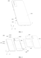
- FIG. 1 is a schematic diagram of a structure of the terminal device 100 according to some embodiments of this application
- FIG. 2 is an exploded view of the terminal device 100 shown in FIG. 1 .
- the terminal device 100 shown in FIG. 1 is described by using the phablet as an example.
- the terminal device 100 includes a screen 101, a middle frame 102, a back cover 103, a primary circuit board 104, a secondary circuit board 105, a battery 107, and a vibration motor 108.
- FIG. 1, FIG. 2 , and the following related accompanying drawings merely show examples of some components included in the terminal device 100. Actual shapes, actual sizes, actual positions, and actual structures of these components are not limited by FIG. 1, FIG. 2 , or any of the following accompanying drawings.
- the terminal device 100 when the terminal device 100 is a device in some other forms, the terminal device 100 may alternatively not include the screen 101.
- the terminal device 100 is in the shape of a rectangular flat plate. For ease of description of the following embodiments, an XYZ coordinate system is established.
- a width direction of the terminal device 100 is defined as an X-axis direction
- a length direction of the terminal device 100 is defined as a Y-axis direction
- a thickness direction of the terminal device 100 is defined as a Z-axis direction.
- the coordinate system of the terminal device 100 may be flexibly set based on an actual requirement. This is not specifically limited herein.
- the terminal device 100 may be alternatively in the shape of a square flat plate, a round flat plate, an elliptical flat plate, or the like.
- the screen 101 is configured to display images, videos, and the like.
- the screen 101 includes a light-transmitting cover plate 101a and a display 101b (English name: panel, also referred to as display panel).
- the light-transmitting cover plate 101a and the display 101b are stacked and fixedly connected through adhesion or the like.
- the light-transmitting cover plate 101a is mainly configured to provide protection and dustproofing functions for the display 101b.
- a material of the light-transmitting cover plate 101a includes but is not limited to glass.
- the display 101b may be a flexible display or a rigid display.
- the display 101b may be an organic light-emitting diode (organic light-emitting diode, OLED) display, an active-matrix organic light-emitting diode (active-matrix organic light-emitting diode, AMOLED) display, a mini light-emitting diode (mini organic light-emitting diode) display, a micro light-emitting diode (micro organic light-emitting diode) display, a micro organic light-emitting diode (micro organic light-emitting diode) display, a quantum dot light emitting diode (quantum dot light emitting diodes, QLED) display, a liquid crystal display (liquid crystal display, LCD), or the like.
- OLED organic light-emitting diode
- AMOLED active-matrix organic light-emitting diode
- mini light-emitting diode mini organic light-emitting diode
- micro light-emitting diode
- FIG. 3 is a sectional view along line A-A in FIG. 1 .
- the middle frame 102 includes a bezel 1021 and a middle plate 1022.
- the bezel 1021 is in the shape of a rectangular ring.
- the middle plate 1022 is fixed to an inner surface of the bezel 1021 around its perimeter. In other words, the bezel 1021 encircles an outer edge of the middle plate 1022.
- the middle plate 1022 may be fixed to the bezel 1021 through welding, or the middle plate 1022 and the bezel 1021 may be an integrally formed structure.
- the screen 101 is fixed to the bezel 1021, and the bezel 1021 may encircle an edge of the screen 101.
- the light-transmitting cover plate 101a is fixed to the bezel 1021. In some embodiments, the light-transmitting cover plate 101a may be fixed to the bezel 1021 through adhesion.
- the bezel 1021 may be alternatively disposed only on one side edge, two adjacent side edges, two opposite side edges, or three side edges of the middle plate 1022. This is not specifically limited herein.
- the back cover 103 is located on a side of the middle plate 1022 farther away from the screen 101, and the back cover 103 is fixed to the bezel 1021.
- the back cover 103 may be fixedly connected to an end face of an end of the bezel 1021 farther away from the screen 101 through adhesion.
- the back cover 103 and the bezel 1021 may be an integrally formed structure, that is, the bezel 1021 and the back cover 103 are an integral structure.
- An accommodating cavity C1 is surrounded by the back cover 103 and the middle frame 102.
- the primary circuit board 104, the secondary circuit board 105, the battery 107, and the vibration motor 108 may be accommodated in the accommodating cavity C1.
- the primary circuit board 104 is configured to integrate a control chip.
- the control chip may be, for example, an application processor (application processor, AP), a double data rate (double data rate, DDR) synchronous dynamic random access memory, or a universal flash storage (universal flash storage, UPS).
- the primary circuit board 104 is electrically connected to the display 101b, and the primary circuit board 104 is configured to control the display 101b to display images or videos.
- the primary circuit board 104 may be a rigid circuit board, a flexible circuit board, or a rigid-flex circuit board.
- the primary circuit board 104 may be an FR-4 dielectric slab, a Rogers (Rogers) dielectric slab, a hybrid FR-4/Rogers dielectric slab, or the like.
- FR-4 is a code of a flameretardant material level
- the Rogers dielectric slab is a high-frequency board.
- the secondary circuit board 105 is configured to integrate electronic components such as a radio frequency front-end of an antenna (for example, a 5G antenna) and a universal serial bus (universal serial bus, USB) device.
- the secondary circuit board 105 may be a rigid circuit board, a flexible circuit board, or a rigid-flex circuit board.
- the secondary circuit board 105 may be an FR-4 dielectric slab, a Rogers (Rogers) dielectric slab, a hybrid FR-4/Rogers dielectric slab, or the like.
- the secondary circuit board 105 is connected to the primary circuit board 104 via a connection component 106, to implement data and signal transmission between the secondary circuit board 105 and the primary circuit board 104.
- the connection component 106 may be a flexible circuit board (flexible printed circuit, FPC). In another embodiment, the connection component 106 may be alternatively a conducting wire or an enamelled wire.
- the battery 107 is located between the primary circuit board 104 and the secondary circuit board 105.
- the battery 107 is configured to supply power to electronic components such as the display 101b, the primary circuit board 104, and the secondary circuit board 105 in the terminal device 100.
- the vibration motor 108 is configured to implement functions such as notification of incoming calls, messages, SMS messages, weather, or news, and haptic feedback for trigger or accidental trigger.
- the vibration motor 108 is located in the accommodating cavity C1. There may be one or more vibration motors 108 disposed in the terminal device 100. This is not specifically limited herein.
- FIG. 4 is a stereogram of the vibration motor 108 in the terminal device 100 shown in FIG. 3 .
- a coordinate system in FIG. 4 is the same as the coordinate system in FIG. 1 .
- position relationships between all components in the vibration motor 108 in FIG. 4 in the coordinate system shown in FIG. 4 are the same as position relationships between all the components in the vibration motor 108 in the coordinate system shown in FIG. 1 when the vibration motor 108 is applied to the terminal device 100 shown in FIG. 1 .
- the vibration motor 108 includes a housing 1.
- the housing 1 is approximately in the shape of a cuboid.
- the housing 1 is provided with an accommodating space inside.
- the accommodating space is used to accommodate components such as a mass block and a driving assembly of the vibration motor 108.
- a height direction of the housing 1 is parallel to the Z-axis direction.
- a length direction of the housing 1 is parallel to the X-axis direction.
- a width direction of the housing 1 is parallel to the Y-axis direction.
- a length direction of the housing 1 may be parallel to the Y-axis direction, and a width direction of the housing 1 is parallel to the X-axis direction.
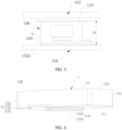
- FIG. 5 is a schematic diagram of an assembly structure between the vibration motor 108 shown in FIG. 4 , and the middle frame 102 and the back cover 103.
- the housing 1 is bonded to the middle plate 1022 of the middle frame 102 via an adhesive 109.
- the housing 1 may be alternatively fixed to the middle plate 1022 of the middle frame 102 through clamping, threaded connection, or the like.
- a side of the housing 1 farther away from the middle plate 1022 is further provided with a limiting structure 110.
- the limiting structure 110 is fixedly connected to the middle frame 102.
- the limiting structure 110 is configured to prevent the housing 1 from moving in a direction leaving the middle plate 1022.
- a mounting height h of the vibration motor 108 on the middle frame 102 is a sum of a thickness of the adhesive 109, a height by which the vibration motor 108 protrudes from the middle plate 1022, and a thickness of the limiting structure 110.
- a height by which the housing 1 of the vibration motor 108 protrudes from the middle plate 1022 is an important factor that affects a thickness of the terminal device 100.
- the housing 1 of the vibration motor 108 is in the shape of a cuboid, and when the vibration motor 108 is mounted on the middle plate 1022 of the middle frame 102, the housing 1 entirely protrudes from the middle plate 1022 in the height direction of the housing 1.
- a height of the housing 1 needs to be reduced, and volumes of structures such as the mass block, a magnet assembly, a coil, and a damping structure inside the housing 1 also need to be correspondingly reduced, which has considerable impact on performance of the vibration motor 108.
- FIG. 6 is a stereogram of the vibration motor 108 according to some embodiments of this application
- FIG. 7a is an exploded view of the housing 1 of the vibration motor 108 shown in FIG. 6 .
- the vibration motor 108 includes the housing 1, where the housing 1 is configured to perform waterproofing and dustproofing protection on structures inside the vibration motor 108.
- a material of the housing 1 is metal, for example, stainless steel. In this way, a thickness of the housing 1 can be designed to be comparatively small on condition that structural strength is ensured. This helps reduce a thickness and volume of the vibration motor 108.
- the housing 1 is made of a metallic material having a magnetic insulation property. In this way, the housing 1 can prevent a magnetic field inside the vibration motor 108 from affecting performance of an antenna that is located around the vibration motor 108 and that is in the terminal device 100.
- the housing 1 includes a side frame 13, a first wall plate 11, and a second wall plate 12.
- the side frame 13 is in the shape of a rectangular ring.
- the side frame 13 includes a first side plate 131 and a second side plate 132 that are disposed opposite each other, and a third side plate 133 and a fourth side plate 134 that are disposed opposite each other.
- the first side plate 131, the third side plate 133, the second side plate 132, and the fourth side plate 134 are sequentially connected end to end, thereby forming the side frame 13 through enclosure.
- the first wall plate 11 and the second wall plate 12 are disposed at two ends of the side frame 13 and opposite each other.
- An accommodating space 1a is limited between the first wall plate 11, the side frame 13, and the second wall plate 12. It can be understood that, in another embodiment, the side frame 13 may be alternatively in the shape of a circular ring or an elliptical ring.
- the housing 1 is formed by assembling two or more parts together, or may be formed as a whole through folding.
- the side frame 13 and the second wall plate 12 are an integral structure, and the first wall plate 11 is fixedly connected to the side frame 13 through screwing, adhesion, welding, or the like.
- the side frame 13 and the first wall plate 11 are an integral structure, and the second wall plate 12 is fixedly connected to the side frame 13 through screwing, adhesion, welding, or the like.
- the side frame 13 is an integral structure, and the first wall plate 11 and the second wall plate 12 are fixedly connected to the side frame 13 through screwing, adhesion, welding, or the like.
- first wall plate 11 and part of the side frame 13 constitute a first part of the housing 1
- second wall plate 12 and part of the side frame 13 constitute a second part of the housing 1, where the first part and the second part are fixedly connected to each other through screwing, adhesion, welding, or the like.
- first part is an integral structure
- second part is an integral structure.
- the first wall plate 11 is in the shape of a flat plate.
- the first wall plate 11 is a rectangular plate structure.
- a length direction of the first wall plate 11 is parallel to the X-axis direction.
- a width direction of the first wall plate 11 is parallel to the Y-axis direction.
- the first wall plate 11 has a first short side 111 and a second short side 112 that are opposite each other, and a first long side 113 and a second long side 114 that are opposite each other.
- An outer surface of the first wall plate 11 is provided with a first protruding portion 115 that protrudes in a direction leaving the accommodating space 1a.
- the first protruding portion 115 is hollow inside so that a first accommodating compartment 115a is formed.
- the first accommodating compartment 115a communicates with the accommodating space 1a. In this way, some internal structures such as a coil 42 and a driving assembly 4 of the vibration motor 108 can be accommodated in the first accommodating compartment 115a.
- the "outer surface of the first wall plate 11" is a surface of a side of the first wall plate 11 farther away from the accommodating space 1a, that is, a surface of a side of the first wall plate 11 farther away from the second wall plate 12.
- the first wall plate 11 is provided with a through communication opening 116, the first protruding portion 115 is disposed at the communication opening 116, and the first accommodating compartment 115a in the first protruding portion 115 communicates with the accommodating space 1a in the housing 1 through the communication opening 116.
- the first protruding portion 115 includes a first top wall 1151 and a first encircling wall 1152.
- the first encircling wall 1152 is in the shape of a ring.
- the first encircling wall 1152 encircles an outer edge of the first top wall 1151.
- the first accommodating compartment 115a is limited between the first top wall 1151 and the first encircling wall 1152.
- An end of the first encircling wall 1152 farther away from the first top wall 1151 is fixedly connected to the first wall plate 11.
- the first encircling wall 1152 is perpendicular to the first top wall 1151.
- an inner surface of the first encircling wall 1152 is level with an inner surface of the communication opening 116.
- an orthographic projection of the first protruding portion 115 on a plane in which the first wall plate 11 is located is a first projection, and an outline of the first projection coincides with an outline of the communication opening 116.
- FIG. 7b is a sectional view of the housing 1 of the vibration motor 108 according to some other embodiments of this application.
- the first encircling wall 1152 of the first protruding portion 115 may alternatively surround an outer side of the communication opening 116.
- the outline of the first projection is located on an outer side of the outline of the communication opening 116.
- the outline of the orthographic projection of the first protruding portion 115 on the first wall plate 11 is in the shape of a circle, a rectangle, a rounded rectangle, a runway, an ellipse, or an irregular figure.
- a specific shape of the outline of the first projection may be adjusted and designed based on a shape of a specific component accommodated in the first accommodating compartment 115a. This is not specifically limited in this application.
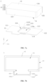
- FIG. 8 is a schematic diagram of a partial structure of the middle plate 1022 of the middle frame 102 according to some embodiments of this application.
- the middle plate 1022 has a first surface 1022a and a second surface 1022b that are opposite each other.
- the first surface 1022a faces the back cover 103.
- the second surface 1022b faces the screen 101.
- the first surface 1022a is provided with a recess 1022c recessed toward the second surface 1022b.
- An opening of the recess 1022c faces away from the screen 101.
- the surface of the side of the middle plate 1022 farther away from the screen 101 is provided with the recess 1022c.
- a bottom wall of the recess 1022c is provided with a first avoiding hole 1023.
- the first avoiding hole 1023 is a through hole that penetrates the bottom wall of the recess 1022c.
- the first avoiding hole 1023 may be alternatively a blind hole.
- the "bottom wall of the recess 1022c" is a wall face of the recess 1022c opposite the opening of the recess 1022c.
- FIG. 9 is a schematic diagram of assembly of the vibration motor 108 shown in FIG. 6 and the middle plate 1022 of the middle frame 102 shown in FIG. 8 .
- the vibration motor 108 is disposed in the recess 1022c. Specifically, part of the vibration motor 108 may be accommodated in the recess 1022c, and the other part of the vibration motor 108 is located outside the recess 1022c. In another embodiment, alternatively, the entire vibration motor 108 may be disposed in the recess 1022c.
- the vibration motor 108 As at least part of the vibration motor 108 is disposed in the recess 1022c, the height by which the vibration motor 108 protrudes from the middle plate 1022 can be reduced, thereby thinning the terminal device 100 and ensuring overall structural strength of the middle frame 102.
- the middle plate 1022 may be provided with no recess 1022c.
- the first avoiding hole 1023 is directly formed in the middle plate 1022.
- the outer surface of the first wall plate 11 faces the middle frame 102, and the first protruding portion 115 is accommodated in the first avoiding hole 1023.
- the outer surface of the first wall plate 11 is fixedly connected to the bottom wall of the recess 1022c via the adhesive 109.
- the first wall plate 11 is provided with the first protruding portion 115 that is hollow inside, so that some components such as the coil and the mass block of the vibration motor 108 can be accommodated in the first accommodating compartment 115a in the first protruding portion 115; in addition, the middle frame 102 is provided with the first avoiding hole 1023 corresponding to the first protruding portion 115, so that the first protruding portion 115 is accommodated in the first avoiding hole 1023. In this way, the height by which the vibration motor 108 protrudes from the middle plate 1022 can be reduced, thereby reducing the mounting height of the vibration motor 108.
- volume of structures such as the mass block, the coil, the magnet assembly, and the damping structure inside the vibration motor 108 can be increased without increasing overall space occupied by the vibration motor 108, so that overall performance of the vibration motor 108 can be improved without increasing the thickness of the terminal device 100.
- the mounting height of the vibration motor 108 can be reduced, so that the space occupied by the vibration motor 108 can be reduced, thereby thinning the terminal device 100.
- a distance between an end of the first protruding portion 115 farther away from the first wall plate 11 and the outer surface of the first wall plate 11 is a first distance d1
- a distance between the second surface 1022b (namely, a surface of a side of the middle plate 1022 closer to the screen 101) of the middle plate 1022 and the outer surface of the first wall plate 11 is a second distance d2.
- the first distance d1 is less than the second distance d2.
- the first distance d1 may be equal to the second distance d2. In this way, the first protruding portion 115 can be prevented from extending out of the first avoiding hole 1023, thereby avoiding interference between the first protruding portion 115 and a component such as the screen 101 of the terminal device 100.
- the first protruding portion 115 and the first wall plate 11 are an integral structure.
- the first protruding portion 115 may be formed through stamping by using a stamping process.
- the first protruding portion 115 and the first wall plate 11 may be separated in structure.
- the first protruding portion 115 may be fixedly connected to the first wall plate 11 through adhesion, welding, clamping, screwing, or the like.
- FIG. 10a is a sectional view of the housing 1 of the vibration motor 108 according to some other embodiments of this application.
- the first protruding portion 115 in this embodiment further includes a flanging portion 1153 in addition to the first encircling wall 1152 and the first top wall 1151 of the first protruding portion 115 shown in FIG. 9 .
- one end of the flanging portion 1153 is fixedly connected to the end of the first encircling wall 1152 farther away from the first top wall 1151, and the other end of the flanging portion 1153 extends in a direction leaving the first encircling wall 1152.
- the flanging portion 1153 is parallel to the plane in which the first wall plate 11 is located.
- the first protruding portion 115 may be fixedly connected to the first wall plate 11 via the flanging portion 1153.
- the flanging portion 1153 is fixedly connected to the outer surface of the first wall plate 11.
- FIG. 10b FIG.
- FIG. 10b is a sectional view of the housing 1 of the vibration motor 108 according to some still other embodiments of this application.
- the flanging portion 1153 is fixedly connected to an inner surface of the first wall plate 11.
- FIG. 10c is a sectional view of the housing 1 of the vibration motor 108 according to some still other embodiments of this application.
- part of the flanging portion 1153 is fixedly connected to an inner surface of the first wall plate 11, and the other part of the flanging portion 1153 is fixedly connected to the outer surface of the first wall plate 11.
- the following describes an internal structure of the vibration motor 108 in some embodiments of this application. There are a plurality of types of internal structures of the vibration motor 108.
- FIG. 11 is an exploded view of the vibration motor 108 shown in FIG. 6
- FIG. 12 is a top view of the vibration motor 108 shown in FIG. 6
- FIG. 13 is a sectional view along line B-B in FIG. 12
- the vibration motor 108 further includes a mass block 2, an elastic assembly 3, a driving assembly 4, a damping structure 5, and an electrical connection structure 6.
- FIG. 11 to FIG. 13 merely show an example of some components included in the vibration motor 108. Actual shapes, actual sizes, actual positions, and actual structures of these components are not limited by FIG. 11 to FIG. 13 .
- the mass block 2 is located in the housing 1.
- the mass block 2 is in the shape of a cuboid. In some other embodiments, the mass block 2 may be alternatively in the shape of a cube, a sphere, an ellipsoid, an irregular shape, or the like.
- the mass block 2 can reciprocatively vibrate in a plane that is parallel to the plane in which the first wall plate 11 is located. Specifically, in the plane that is parallel to the plane in which the first wall plate 11 is located, a vibration path of the mass block 2 may be a straight line or a curve.
- the vibration path of the mass block 2 is a straight line.
- the mass block 2 may reciprocatively vibrate along a direction A1.
- the vibration motor 108 is a transverse linear motor.
- a vibration direction of the mass block 2 is perpendicular to the thickness direction of the terminal device 100. This helps reduce the mounting height of the vibration motor 108 in the terminal device 100.
- a vibration direction of the mass block 2 may be perpendicular to the plane in which the first wall plate 11 is located.
- the vibration motor 108 is a longitudinal linear motor.
- the vibration motor 108 may be alternatively a rotor motor.
- the vibration motor 108 may be an X-axis vibration motor, and the mass block 2 vibrates along the X-axis direction, so that the terminal device 100 generates vibration in the X-axis direction. It can be understood that the vibration direction of the mass block 2 may be set based on an actual requirement. This is not limited in this application. All of the following embodiments are described based on the case that the vibration motor 108 is the X-axis vibration motor, which shall not be considered as a special limitation on this application.
- the elastic assembly 3 is configured to elastically support the mass block 2 in the housing 1, and the elastic assembly 3 allows the mass block 2 to reciprocatively vibrate along the direction A1 in the housing 1.
- the elastic assembly 3 includes a first elastic part 31 and a second elastic part 32.
- the first elastic part 31 and the second elastic part 32 are both spring plates.
- An arrangement direction of the first elastic part 31, the mass block 2, and the second elastic part 32 is parallel to the vibration direction A1 of the mass block 2.
- the first elastic part 31 includes a first fixing portion 311, a first connection portion 313, and a second fixing portion 312 that are sequentially connected.
- the first fixing portion 311 is connected to the mass block 2, where manners of the connection include but are not limited to welding and bonding.
- the second fixing portion 312 is connected to the first side plate 131 of the side frame 13 in the housing 1, where manners of the connection include but are not limited to welding and bonding.
- the first connection portion 313 is approximately n-shaped. An arching direction A2 of the first connection portion 313 is parallel to the plane in which the first wall plate 11 is located, and the arching direction A2 of the first connection portion 313 is perpendicular to the vibration direction A1 of the mass block 2.
- the second elastic part 32 includes a third fixing portion 321, a second connection portion 323, and a fourth fixing portion 322 that are sequentially connected.
- the third fixing portion 321 is connected to the mass block 2, where manners of the connection include but are not limited to welding and bonding.
- the fourth fixing portion 322 is connected to the second side plate 132 of the side frame 13 in the housing 1, where manners of the connection include but are not limited to welding and bonding.
- the second connection portion 323 is approximately n-shaped. An arching direction A3 of the second connection portion 323 is opposite to the arching direction A2 of the first connection portion 313.
- the first elastic part 31 and the second elastic part 32 are both capable of deforming along a direction parallel to the vibration direction A1 of the mass block 2.
- an included angle between two arm portions of the first connection portion 313 is reduced, and an included angle between two arm portions of the second connection portion 323 is increased.
- the mass block 2 vibrates in a direction approaching the second side plate 132 the included angle between the two arm portions of the first connection portion 313 is increased, and the included angle between the two arm portions of the second connection portion 323 is reduced.
- Such a structure is simple and easy to implement.
- the elastic assembly 3 may be alternatively designed into another structural form, which is not specifically limited herein.
- the driving assembly 4 is configured to drive the mass block 2 to reciprocatively vibrate in the plane that is parallel to the plane in which the first wall plate 11 is located.
- the driving assembly 4 includes a magnet assembly 41 and a coil 42.
- the magnet assembly 41 is fixed to the mass block 2.
- the coil 42 is configured to cooperate with the magnet assembly 41 to drive the mass block 2 to reciprocatively vibrate relative to the housing 1 in the plane that is parallel to the plane in which the first wall plate 11 is located.
- the coil 42 and the magnet assembly 41 cooperate to generate a Lorentz force, and the Lorentz force can drive the mass block 2 to reciprocatively vibrate in the plane that is parallel to the plane in which the first wall plate 11 is located.
- FIG. 14 is a stereogram of the mass block 2 in the vibration motor 108 shown in FIG. 11 .
- the mass block 2 is provided with a mounting slot 21, and the magnet assembly 41 is accommodated and fixed in the mounting slot 21.
- one end of the mounting slot 21 is open, and the open end of the mounting slot 21 faces the first wall plate 11. In this way, an overall height of the vibration motor 108 can be reduced.
- both ends of the mounting slot 21 may be open.
- the mass block 2 may be provided with no mounting slot 21.
- the magnet assembly 41 may be disposed on an outer surface of the mass block 2.
- the coil 42 and the magnet assembly may be arranged in the height direction of the housing 1. Specifically, the coil 42 is located on a side of the magnet assembly 41 closer to the first wall plate 11.
- FIG. 15 is an exploded view of the magnet assembly 41 in the vibration motor 108 shown in FIG. 11 .
- the magnet assembly 41 includes a first magnet 411, a second magnet 412, and a magnetoconductive part 413.
- the first magnet 411 and the second magnet 412 are arranged at an interval in a direction parallel to the first wall plate 11.
- the first magnet 411 and the second magnet 412 are arranged at an interval in the direction A1.
- the first magnet 411 and the second magnet 412 may be iron magnets or steel magnets.
- a magnetization direction of the first magnet 411 and a magnetization direction of the second magnet 412 are both perpendicular to the plane in which the first wall plate 11 is located, and the magnetization direction of the first magnet 411 is opposite to the magnetization direction of the second magnet 412.
- the magnetization direction is a direction from the north pole (namely, the N pole) to the south pole (namely, the S pole).
- the magnetoconductive part 413 is located between the first magnet 411 and the second magnet 412. Specifically, the first magnet 411 and the second magnet 412 are fixedly connected to two opposite side faces of the magnetoconductive part 413, respectively.
- the magnetoconductive part 413 may be a yoke made of stacked silicon steel sheets. Therefore, the magnetoconductive part 413 is disposed between the first magnet 411 and the second magnet 412, so that magnetic current strength between the first magnet 411 and the second magnet 412 can be increased, thereby increasing strength of driving the mass block 2. In this way, a vibration effect is good, and magnetic leakage can be reduced, thereby increasing energy utilization.
- the first magnet 411 and the second magnet 412 may be integrated by using the magnetoconductive part 413, thereby facilitating overall assembly of the magnet assembly 41.
- an end of the first magnet 411 farther away from the first wall plate 11 is the S pole and an end of the first magnet 411 closer to the first wall plate 11 is the N pole
- an end of the second magnet 412 farther away from the first wall plate 11 is the N pole and an end of the second magnet 412 closer to the first wall plate 11 is the S pole.
- an end of the first magnet 411 farther away from the first wall plate 11 may be the N pole and an end of the first magnet 411 closer to the first wall plate 11 is the S pole, in which case an end of the second magnet 412 farther away from the first wall plate 11 is the S pole and an end of the second magnet 412 closer to the first wall plate 11 is the N pole.
- the first magnet 411 and the second magnet 412 When the coil 42 is powered on, the first magnet 411 and the second magnet 412 generate Lorentz forces F1 and F2 whose directions are parallel to the direction A1.
- the direction of F1 is the same as that of F2.
- a combination of F1 and F2 can drive the mass block 2 to unidirectionally move in the plane that is parallel to the plane in which the first wall plate 11 is located.
- the mass block 2 can be driven to reciprocatively vibrate through current commutation of the coil 42.
- the magnet assembly 41 may alternatively include only one of the first magnet 411 and the second magnet 412, so that one of F1 and F2 drives the mass block 2 to move in the plane that is parallel to the plane in which the first wall plate 11 is located.
- the magnet assembly 41 may alternatively include only the first magnet 411 and the second magnet 412 and be provided with no magnetoconductive part 413.
- a third magnet rather than the magnetoconductive part 413 may be disposed between the first magnet 411 and the second magnet 412, where the third magnet is an iron magnet or a steel magnet.
- a Halbach array is formed between the first magnet 411, the second magnet 412, and the third magnet, so that magnetic forces can be concentrated toward the mass block 2, thereby increasing strength of driving the mass block 2.
- the Halbach array is a permanent-magnet arrangement manner, where permanent magnets with different magnetization directions are arranged in a specific order, so that a magnetic field on one side of the Halbach array is significantly strengthened and a magnetic field on the other side of the Halbach array is significantly weakened.
- the electrical connection structure 6 is configured to lead an electrode of the coil 42 out of the housing 1.
- the electrical connection structure 6 may be but is not limited to a printed circuit board (printed circuit board, PCB), a flexible circuit board (flexible printed circuit board, FPC), or a structure formed by connecting a plurality of conducting wires via a flexible structure.
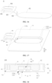
- FIG. 16 is a stereogram of the electrical connection structure 6 in the vibration motor 108 shown in FIG. 11 .
- the electrical connection structure 6 includes a first segment 61, a second segment 62, and a third segment 63 that are sequentially connected.
- FIG. 17 is a schematic diagram of assembly of the electrical connection structure 6 shown in FIG. 16 and the first wall plate 11.
- the first segment 61 is fixed to a compartment bottom wall of the first accommodating compartment 115a
- the second segment 62 is fixed to an inner side wall of the first accommodating compartment 115a.
- the first segment 61 is fixed to an inner surface of the first top wall 1151
- the second segment 62 is fixed to an inner surface of the first encircling wall 1152.
- the coil 42 is fixed to the first segment 61 and electrically connected to the first segment 61.
- An extension path of the third segment 63 is parallel to the plane in which the first wall plate 11 is located, and part of the third segment 63 is located outside the housing 1.
- the part of the third segment 63 located outside the housing 1 is provided with a positive terminal 64 and a negative terminal 65.
- the electrical connection structure 6 may be electrically connected to the primary circuit board 104 or the secondary circuit board 105 via the positive terminal 64 and the negative terminal 65, thereby implementing an electrical connection between the coil 42 and the primary circuit board 104 or the secondary circuit board 105.
- the first wall plate 11 is provided with a supporting portion 117.
- the supporting portion 117 and the first wall plate 11 are coplanar.
- the part of the electrical connection structure 6 located outside the housing 1 is fixedly connected to the supporting portion 117.
- the supporting portion 117 and the first wall plate 11 are an integral structure.
- the supporting portion 117 and the first wall plate 11 are integrated. This can simplify a processing process of the vibration motor 108, reduce processing costs, and increase connection strength between the supporting portion 117 and the first wall plate 11.
- the first wall plate 11 may be alternatively provided with no supporting portion 117.
- the third segment 63 of the electrical connection structure 6 may be fixed and supported via the middle frame 102.
- the vibration motor 108 is applied to the terminal device 100
- the third segment 63 of the electrical connection structure 6 is attached and fixed to the middle frame 102, thereby fixing and supporting the third segment 63 via the middle frame 102.
- part of the coil 42 may be located in the first accommodating compartment 115a, and the other part of the coil 42 is located in the accommodating space 1a. In this way, the accommodating space 1a occupied by the coil 42 in the housing 1 can be reduced.
- the entire coil 42 may be accommodated in the first accommodating compartment 115a.
- a shape of the first accommodating compartment 115a is adapted to a shape of the coil 42. In this way, space utilization in the first accommodating compartment 115a can be maximized, and assembly difficulty of the coil 42 can be reduced.
- an end of the coil 42 farther away from the first wall plate 11 is accommodated in the mounting slot 21.
- part of the coil 42 may be accommodated in the first accommodating compartment 115a, and the other part of the coil 42 may be accommodated in the mounting slot 21.
- the damping structure 5 is configured to provide damping for the mass block 2 so as to implement a function of quickly stopping vibration of the mass block 2.
- the damping structure 5 and the coil 42 cooperate to provide electromagnetic damping for the mass block 2.
- the damping structure 5 forms a plate structure, and the damping structure 5 may be located on a side of the magnet assembly 41 farther away from the coil 42.
- the damping structure 5 and the coil 42 are respectively located on two sides of the magnet assembly 41.
- the damping structure 5 and the coil 42 may be located on one side of the magnet assembly 41.
- the damping structure 5 may be bonded or welded to an inner surface of the second wall plate 12.
- the damping structure 5 may be made of a material whose resistivity is low.
- the damping structure 5 may be a metal piece such as an iron piece, an aluminum piece, a copper piece, or a silver piece.
- the damping structure 5 may be a ring-shaped damping copper plate.
- the coil 42 When the coil 42 is powered on, the coil 42 generates a changing electromagnetic field, and the magnet assembly 41 is subject to a magnetic field force. Under the action of the magnetic field force, the mass block 2 performs simple harmonic motion between the first elastic part 31 and the second elastic part 32. Meanwhile, a magnetic line of the magnet assembly 41 cuts a magnetic induction line of the damping copper plate, and an induced current and an induced electromotive force are to be generated in the damping copper plate.
- a magnetic field force generated by the induced current of the damping copper plate obstructs motion of the mass block 2, so that the mass block 2 can quickly stop vibrating.
- the damping structure 5 may be alternatively a magnetic liquid.
- the magnetic liquid is a colloidal substance having a magnetic property.
- outer layers of nanometric-scale magnetic particles for example, nickel, cobalt, or iron oxides
- a base fluid such as water, organic solvent, or oil
- the magnetic liquid may adhere to an outer surface of the magnet assembly 41.
- the damping structure 5 may be alternatively a magnetic liquid, a silica gel, a foam, or the like.
- the accommodating space 1a occupied by the electrical connection structure 6 and the coil 42 in the housing 1 can be reduced, so that the structure of the vibration motor 108 is more compact; in addition, the volumes of the structures such as the mass block 2 and the magnet assembly 41 of the vibration motor 108 can be increased without increasing the overall mounting height of the vibration motor 108, so that the overall performance of the vibration motor 108 can be improved without increasing the thickness of the terminal device 100.
- the mounting height of the vibration motor 108 can be reduced, thereby thinning the terminal device 100.
- another structure in the vibration motor 108 may be disposed in the first accommodating compartment 115a.
- FIG. 18 is a sectional view of the vibration motor 108 according to some other embodiments of this application.
- a difference between the vibration motor 108 in this embodiment and the vibration motor 108 shown in FIG. 13 lies in that, in the vibration motor 108 in the embodiment shown in FIG. 13 , the first segment 61 of the electrical connection structure 6 and part of the coil 42 are disposed in the first accommodating compartment 115a, whereas in the vibration motor 108 in this embodiment, only the first segment 61 of the electrical connection structure 6 is disposed in the first accommodating compartment 115a and the entire coil 42 is located in the accommodating space 1a.
- FIG. 19 is a schematic diagram of assembly of the vibration motor 108 and the middle frame 102 according to some still other embodiments of this application.
- a difference between the vibration motor 108 in this embodiment and the vibration motor 108 shown in FIG. 18 lies in that the damping structure 5 of the vibration motor in this embodiment is disposed in the first accommodating compartment 115a, the first segment 61 of the electrical connection structure 6 is fixed to an inner surface of the second wall plate 12, and the coil 42 is fixedly connected to the first segment 61 of the electrical connection structure 6.
- an opening of the mounting slot 21 of the mass block 2 in this embodiment faces the second wall plate 12.
- the mass block 2 in this embodiment is rotated by 180° relative to the mass block 2 in the vibration motor 108 shown in FIG. 18 .
- FIG. 20a is a schematic diagram of assembly of the vibration motor 108 and the middle frame 102 according to some still other embodiments of this application.
- FIG. 20b is a stereogram of the mass block 2 in the vibration motor 108 shown in FIG. 20a .
- the mass block 2 in this embodiment is provided with a second protruding portion 22.
- the damping structure 5 and the second protruding portion 22 are both accommodated in the first accommodating compartment 115a.
- an outer encircling wall of the second protruding portion 22 and the first encircling wall 1152 of the first protruding portion 115 need to be disposed at an interval, and a vibration stroke of the mass block 2 needs to be reserved.
- FIG. 21 is a schematic diagram of assembly of the vibration motor 108 and the middle frame 102 according to some still other embodiments of this application.
- a difference between the vibration motor 108 in this embodiment and the vibration motor 108 shown in FIG. 20a lies in that, in the vibration motor 108 in this embodiment, the mass block 2 is provided with a second protruding portion 22, where only the second protruding portion 22 of the mass block 2 is accommodated in the first accommodating compartment 115a, and the damping structure 5 (not shown in FIG. 21 ) is disposed in a position other than the first accommodating compartment 115a.
- the damping structure 5 in this embodiment may be a magnetic liquid, a silica gel, a foam, or the like.
- volumes of structures such as the mass block 2 of the vibration motor 108 can be further increased without increasing the overall space occupied by the vibration motor 108, so that the overall performance of the vibration motor 108 can be improved without increasing the thickness of the terminal device 100.
- the mounting height of the vibration motor 108 can be reduced, so that the space occupied by the vibration motor 108 can be reduced, thereby thinning the terminal device 100.
- structures of the magnet assembly 41 and the coil 42 may be alternatively designed into other structural forms.
- FIG. 22 is an exploded view of the vibration motor 108 according to some still other embodiments of this application
- FIG. 23 is a top view of assembly of the vibration motor 108 shown in FIG. 22 and the middle plate 1022 of the middle frame 102
- FIG. 24 is a sectional view along line C-C in FIG. 23
- a structure of the driving assembly 4 of the vibration motor 108 in this embodiment is different from that of the driving assembly 4 of the vibration motor 108 shown in FIG. 13 .
- the magnet assembly 41 and the coil 42 of the driving assembly 4 shown in FIG. 13 are disposed at an interval in the height direction of the housing 1, whereas the magnet assembly 41 and the coil 42 in this embodiment are arranged in a direction parallel to the first wall plate 11.
- the magnet assembly 41 and the coil 42 in this embodiment are arranged in the Y-axis direction.
- the magnet assembly 41 includes a first magnet 411 and a second magnet 412 that are spaced apart in the direction A2.
- a magnetic gap K (also referred to as “magnetic gap”) is formed between the first magnet 411 and the second magnet 412.
- the coil 42 is disposed in the magnetic gap K. In this way, sizes of the coil 42 and the magnet assembly 41 in the height direction of the housing 1 can be set to comparatively large values.
- the first segment 61 of the electrical connection structure 6 and part of the coil 42 are disposed in the first accommodating compartment 115a in this embodiment.
- first segment 61 of the electrical connection structure 6 may be disposed in the first accommodating compartment 115a; or the mass block 2 is provided with a second protruding portion 22, where the second protruding portion 22 is disposed in the first accommodating compartment 115a; or the damping structure 5 is disposed in the first accommodating compartment 115a; or the mass block 2 is provided with a second protruding portion 22, where the second protruding portion 22 and the damping structure 5 are both disposed in the first accommodating compartment 115a.
- part of the magnet assembly 41 may be disposed in the first accommodating compartment 115a.
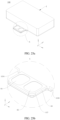
- FIG. 25a is a stereogram of the vibration motor 108 according to some other embodiments of this application
- FIG. 25b is an enlarged view of a region A in FIG. 25a
- FIG. 26 is an exploded view of the vibration motor 108 shown in FIG. 25a .
- a difference between the vibration motor 108 in this embodiment and the vibration motor 108 shown in FIG. 6 lies in that a side wall of the first protruding portion 115 in the vibration motor 108 shown in FIG.
- a side wall of the first protruding portion 115 in this embodiment includes a first side wall 1154 and a second side wall 1155 that are opposite each other.
- the first side wall 1154 and the second side wall 1155 are disposed opposite each other in the X-axis direction. Two ends of the first side wall 1154 in a length direction of the first side wall 1154 both extend to be level with the outer edge of the first wall plate 11. Two ends of the second side wall 1155 in a length direction of the second side wall 1155 both extend to be level with the outer edge of the first wall plate 11. In this way, a processing process of the first protruding portion 115 can be simplified, and accommodating space in the first accommodating compartment 115a can be increased.
- first side wall 1154 and the second side wall 1155 may be alternatively disposed opposite each other in the Y-axis direction.
- a length of the first side wall 1154 is equal to a length of the first short side 111 of the first wall plate 11
- a length of the second side wall 1155 is equal to the length of the first short side 111 of the first wall plate 11.
- FIG. 27a is an exploded view of the housing 1 of the vibration motor 108 shown in FIG. 25a .
- Notches are formed at both ends of the first accommodating compartment 115a in a length direction of the first accommodating compartment 115a.
- blocking plates 135 are disposed on the side frame 13 in positions corresponding to the notches. The blocking plates 135 block the notches.
- the blocking plate 135 is provided with an avoiding opening 135a, and the third segment 63 of the electrical connection structure 6 is disposed in the avoiding opening 135a in a passing-through manner.
- the supporting portion 117 may be disposed on the first top wall 1151 of the first protruding portion 115.
- FIG. 27b is a schematic diagram of assembly of the vibration motor 108 shown in FIG. 26 and the middle frame 102.
- the first avoiding hole 1023 is a blind hole. In this way, airtightness of the middle frame 102 can be ensured, thereby increasing reliability of the terminal device 100.
- FIG. 27c is an exploded view of the vibration motor 108 and the middle frame 102 according to some other embodiments of this application.
- the first wall plate 11 of the vibration motor 108 includes a first wall plate body 11a and an extension plate 11b.
- the extension plate 11b is disposed on an outer edge of the first wall plate body 11a, and the extension plate 11b and the first wall plate body 11a are coplanar.
- FIG. 27d is a schematic diagram of a position relationship between an outline of an orthographic projection of the first avoiding hole 1023 on the plane in which the first wall plate 11 of the vibration motor shown in FIG. 27c is located and the first wall plate 11.
- the orthographic projection of the first avoiding hole 1023 on the plane in which the first wall plate 11 is located is a second projection S.
- the outline of the second projection S is located on the inner side of the outer edge of the first wall plate 11, and the outline of the second projection S and the outer edge of the first wall plate 11 are spaced apart.
- the extension plate 11b may be in the shape of an arc, a polygon, or the like.
- the sealing part is the adhesive 109.
- the sealing effect between the first wall plate 11 and the first avoiding hole 1023 can be ensured, and furthermore, the first wall plate 11 can be fixedly connected to the middle plate 1022 via the adhesive 109, thereby simplifying the structure of the vibration motor 108.
- the terminal device 100 further includes the limiting structure 110.
- a limiting space C2 is limited between the limiting structure 110 and the middle plate 1022.
- the vibration motor 108 is disposed in the limiting space C2.
- FIG. 28 is a stereogram of assembly of the limiting structure 110, the vibration motor 108, and the middle frame 102 in the terminal device 100 according to some embodiments of this application.
- the limiting structure 110 includes a limiting portion 110a and a connection lug 110b.
- the limiting portion 110a is opposite the second wall plate 12 of the vibration motor 108, the limiting portion 110a is in the shape of a long strip, and a length direction of the limiting portion 110a is parallel to the X-axis direction.
- the limiting portion 110a can limit the position of the vibration motor 108 and prevent the vibration motor 108 from moving in the direction leaving the middle plate 1022.
- connection lug 110b is fixedly connected to the limiting portion 110a.
- the limiting structure 110 is fixedly connected to the middle frame 102 via the connection lug 110b.
- connection lug 110b there may be one or more connection lugs 110b.
- the term "a plurality of" in this application means two or more.
- the two connection lugs 110b are fixedly connected to two ends of the limiting portion 110a in a length direction of the limiting portion 110a, respectively.
- the limiting structure 110 is fixedly connected to the middle frame 102 via the two connection lugs 110b.
- the connection lug 110b may be fixedly connected to the middle plate 1022 through screwing, adhesion, clamping, or the like. In this way, the limiting structure 110 can limit the position of the vibration motor 108 and prevent the vibration motor 108 from moving in a direction leaving the middle frame 102.
- the limiting portion 110a and the connection lug 110b are an integral structure. This can simplify a processing process of the limiting structure 110 and reduce processing costs.
- a material of the limiting structure 110 is metal, for example, stainless steel. In this way, the thickness of the limiting structure 110 can be designed to be comparatively small on condition that structural strength is ensured. This helps reduce space occupied by the limiting structure 110.
- FIG. 29 is a top view of the vibration motor 108 shown in FIG. 28, and FIG. 30 is a sectional view along line D-D in FIG. 29 .
- a buffer part 200 is disposed between the vibration motor 108 and the limiting structure 110.
- the buffer part 200 is a foam, a silica gel, or the like.
- the limiting structure 110 may be alternatively another structure, provided that the structure can prevent the vibration motor 108 from moving in the direction leaving the middle plate 1022.
- FIG. 31 is a stereogram of assembly of the vibration motor 108, the middle frame 102, and the limiting structure 110 in the terminal device 100 according to some other embodiments of this application. A difference between the terminal device 100 in this embodiment and the terminal device 100 shown in FIG.
- the vibration motor 108 in this embodiment not only the first wall plate 11 of the housing 1 is provided with the first protruding portion 115, but also the second wall plate 12 of the housing 1 is provided with a third protruding portion 121, and in addition, the limiting portion 110a of the limiting structure 110 is provided with a second avoiding hole 110c corresponding to the third protruding portion 121, so that the third protruding portion 121 is accommodated in the second avoiding hole 110c.
- FIG. 32 is an exploded view of the vibration motor 108 and the limiting structure 110 in the stereogram of assembly shown in FIG. 31 ; and FIG. 33 is a stereogram of the side frame 13 and the second wall plate 12 of the housing 1 in the vibration motor 108 shown in FIG. 32 , viewed from the inside to the outside.
- the second wall plate 12 is in the shape of a rectangular flat plate.
- the second wall plate 12 is opposite the first wall plate 11, and the second wall plate 12 is parallel to the first wall plate 11.
- the second wall plate 12 is provided with the third protruding portion 121 that protrudes in a direction leaving the accommodating space 1a.
- the third protruding portion 121 is hollow inside so that a second accommodating compartment 121a is formed.
- the second accommodating compartment 121a communicates with the accommodating space 1a. In this way, structures inside the vibration motor 108 can be accommodated in the second accommodating compartment 121a.
- the third protruding portion 121 includes a second top wall 1211 and a second encircling wall 1212.
- the second encircling wall 1212 is in the shape of a ring.
- the second encircling wall 1212 encircles an outer edge of the second top wall 1211.
- the second accommodating compartment 121a is limited between the second top wall 1211 and the second encircling wall 1212.
- an outline of an orthographic projection of the second protruding portion 22 on the second wall plate 12 is in the shape of a circle, a rectangle, a rounded rectangle, a runway, an ellipse, or an irregular figure.
- a specific shape of the outline of the orthographic projection of the second protruding portion 22 on the second wall plate 12 may be adjusted and designed based on a shape of a specific component accommodated in the second accommodating compartment 121a. This is not specifically limited in this application.
- the second avoiding hole 110c is a through hole formed in the limiting portion 110a.
- the second avoiding hole 110c may be alternatively a blind hole.
- the buffer part 200 between the vibration motor 108 and the limiting structure 110 is in the shape of a ring.
- the first wall plate 11 is provided with the first protruding portion 115 that is hollow inside and the middle frame 102 is provided with the first avoiding hole 1023 corresponding to the first protruding portion 115, so that the first protruding portion 115 is accommodated in the first avoiding hole 1023;
- the second wall plate 12 is provided with the second protruding portion 22 that is hollow inside and the limiting structure 110 is provided with the second avoiding hole 110c corresponding to the second protruding portion 22, so that the second protruding portion 22 is accommodated in the second avoiding hole 110c.
- the terminal device 100 can be further thinned while the vibration performance of the vibration motor 108 is ensured. Moreover, the overall performance of the vibration motor 108 can be further improved without increasing the thickness of the terminal device 100.
- the following describes layout of the structures inside the vibration motor 108 having the hollow first protruding portion 115 and the hollow second protruding portion 22.
- FIG. 34 is a top view of the stereogram of assembly shown in FIG. 31
- FIG. 35 is a sectional view along line E-E in FIG. 34 .
- Structures of the mass block 2, the elastic assembly 3, the driving assembly 4, the damping structure 5, and the electrical connection structure 6 of the vibration motor 108 in this embodiment are the same as those of the mass block 2, the elastic assembly 3, the driving assembly 4, the damping structure 5, and the electrical connection structure 6 of the vibration motor 108 shown in FIG. 13 .
- the first segment 61 of the electrical connection structure 6 and part of the coil 42 are disposed in the first accommodating compartment 115a, and the damping structure 5 is disposed in the second accommodating compartment 121a.
- the damping structure 5 may be fixed to an inner surface of the second top wall 1211. Therefore, the volumes of the structures such as the mass block 2, the coil 42, and the magnet assembly 41 inside the vibration motor 108 can be increased without increasing the overall space occupied by the vibration motor 108, so that the overall performance of the vibration motor 108 can be improved without increasing the thickness of the terminal device 100.
- the mounting height of the vibration motor 108 can be reduced, so that the space occupied by the vibration motor 108 can be reduced, thereby thinning the terminal device 100.
- FIG. 36 is a schematic diagram of assembly of the limiting structure 110, the vibration motor 108, and the middle plate 1022 of the middle frame 102 according to some still other embodiments of this application.
- a difference between this embodiment and the embodiment shown in FIG. 35 lies in that the mass block 2 in this embodiment is provided with a second protruding portion 22 that protrudes toward the limiting structure 110, where the damping structure 5 and the second protruding portion 22 are both accommodated in the second accommodating compartment 121a.
- the outer encircling wall of the second protruding portion 22 and the second encircling wall 1212 of the third protruding portion 121 need to be disposed at an interval, and a vibration stroke of the mass block 2 needs to be reserved.
- FIG. 37 is a schematic diagram of assembly of the limiting structure 110, the vibration motor 108, and the middle plate 1022 of the middle frame 102 according to some still other embodiments of this application.
- a difference between the vibration motor 108 in this embodiment and the vibration motor 108 shown in FIG. 36 lies in that, in this embodiment, only the second protruding portion 22 of the mass block 2 is accommodated in the second accommodating compartment 121a, and the damping structure 5 (not shown in FIG. 37 ) is disposed in a position other than the second accommodating compartment 121a.
- the damping structure 5 in this embodiment may be a magnetic liquid, a silica gel, a foam, or the like.
- FIG. 37 is a schematic diagram of assembly of the limiting structure 110, the vibration motor 108, and the middle plate 1022 of the middle frame 102 according to some still other embodiments of this application.
- a difference between the vibration motor 108 in this embodiment and the vibration motor 108 shown in FIG. 36 lies in that, in this embodiment, only the second protrud
- FIG. 38a is a schematic diagram of assembly of the limiting structure 110, the vibration motor 108, and the middle plate 1022 of the middle frame 102 according to some still other embodiments of this application.
- the magnet assembly 41 and the coil 42 of the vibration motor 108 in this embodiment are arranged in a direction parallel to the first wall plate 11.
- the first segment 61 of the electrical connection structure 6 and the coil 42 may be disposed in the first accommodating compartment 115a, and the mass block 2 is provided with a second protruding portion 22, where the second protruding portion 22 and the damping structure 5 are accommodated in the second accommodating compartment 121a.
- the first segment 61 of the electrical connection structure 6 and the coil 42 may be disposed in the first accommodating compartment 115a, and only the damping structure 5 or the second protruding portion 22 is accommodated in the second accommodating compartment 121a.
- FIG. 38b is a schematic diagram of assembly of the limiting structure 110, the vibration motor 108, and the middle plate 1022 of the middle frame 102 according to some still other embodiments of this application.
- the first segment 61 of the electrical connection structure 6 and the coil 42 are disposed in the first accommodating compartment 115a, and only the damping structure 5 is accommodated in the second accommodating compartment 121a.
- FIG. 38c is a schematic diagram of assembly of the limiting structure 110, the vibration motor 108, and the middle plate 1022 of the middle frame 102 according to some still other embodiments of this application.
- the first segment 61 of the electrical connection structure 6 and the coil 42 are disposed in the first accommodating compartment 115a, and the second protruding portion 22 is accommodated in the second accommodating compartment 121a.
- FIG. 39a is a schematic diagram of assembly of the limiting structure 110, the vibration motor 108, and the middle plate 1022 of the middle frame 102 according to some still other embodiments of this application.
- a difference between this embodiment and the terminal device 100 shown in FIG. 38b lies in that the mounting slot 21 in the mass block 2 in this embodiment forms a through slot whose two ends are open, the magnet assembly 41 is fixed in the mounting slot 21, and an end of the magnet assembly 41 farther away from the first wall plate 11 is accommodated in the second accommodating compartment 121a.
- the end of the magnet assembly 41 farther away from the first wall plate 11 may pass through the mounting slot 21 and be accommodated in the second accommodating compartment 121a.
- An end of the coil 42 farther away from the first wall plate 11 is accommodated in the second accommodating compartment 121a.
- the end of the coil 42 farther away from the first wall plate 11 may pass through the mounting slot 21 and be accommodated in the second accommodating compartment 121a.
- only the end of the magnet assembly 41 farther away from the first wall plate 11 may be accommodated in the second accommodating compartment 121a, and the end of the coil 42 farther away from the first wall plate 11 is not accommodated in the second accommodating compartment 121a.
- FIG. 39c only the end of the coil 42 farther away from the first wall plate 11 may be accommodated in the second accommodating compartment 121a, and the end of the magnet assembly 41 farther away from the first wall plate 11 is not accommodated in the second accommodating compartment 121a.
- a component disposed in the first accommodating compartment 115a and a component disposed in the second accommodating compartment 121a are interchangeable.
- only the second wall plate 12 may be provided with a third protruding portion 121 whereas the first wall plate 11 is provided with no first protruding portion 115, and the limiting structure 110 is provided with a second avoiding hole 110c corresponding to the third protruding portion 121, so that the third protruding portion 121 is accommodated in the second avoiding hole 110c.
- the volumes of the structures such as the mass block 2, the coil 42, and the magnet assembly 41 inside the vibration motor 108 can also be increased without increasing the overall space occupied by the vibration motor 108, so that the overall performance of the vibration motor 108 can be improved without increasing the thickness of the terminal device 100.
- the mounting height of the vibration motor 108 can be reduced, so that the space occupied by the vibration motor 108 can be reduced, thereby thinning the terminal device 100.
- the following describes layout of the structures inside the vibration motor 108 in which only the second wall plate 12 is provided with the third protruding portion 121 whereas the first wall plate 11 is provided with no first protruding portion 115.
- FIG. 40 is a schematic diagram of assembly of the limiting structure 110, the vibration motor 108, and the middle frame 102 according to some still other embodiments of this application.
- Structures of the mass block 2, the elastic assembly 3, the driving assembly 4, the damping structure 5, and the electrical connection structure 6 of the vibration motor 108 in this embodiment are the same as those of the mass block 2, the elastic assembly 3, the driving assembly 4, the damping structure 5, and the electrical connection structure 6 of the vibration motor 108 shown in FIG. 35 .
- the damping structure 5 is disposed in the second accommodating compartment 121a in the second protruding portion 22 and the electrical connection structure 6 is directly fixedly connected to the inner surface of the first wall plate 11.
- the first segment 61 and the second segment 62 of the electrical connection structure 6 are located in a same plane, and the first segment 61 and the second segment 62 of the electrical connection structure 6 are both fixed to the inner surface of the first wall plate 11.
- FIG. 41 is a schematic diagram of assembly of the limiting structure 110, the vibration motor 108, and the middle frame 102 according to some still other embodiments of this application.
- a difference between the terminal device 100 in this embodiment and the terminal device 100 in FIG. 40 lies in that, in this embodiment, the damping structure 5 is disposed in the second accommodating compartment 121a, and the mass block 2 is further provided with a second protruding portion 22, where the second protruding portion 22 is accommodated in the second accommodating compartment 121a.
- FIG. 42 is a schematic diagram of assembly of the limiting structure 110, the vibration motor 108, and the middle frame 102 according to some still other embodiments of this application.
- the damping structure 5 (not shown in FIG. 42 ) is disposed in a position other than the second accommodating compartment 121a.
- the damping structure 5 and/or the second protruding portion 22 may be disposed in the second accommodating compartment 121a.
- the magnet assembly 41 and the coil 42 when the magnet assembly 41 and the coil 42 are arranged in the direction parallel to the first wall plate 11, the magnet assembly 41 and the coil 42 may also be disposed in the second accommodating compartment 121a.
- FIG. 43 is a sectional view of the vibration motor 108 according to some still other embodiments of this application.
- the magnet assembly 41 and the coil 42 in this embodiment are arranged in the direction parallel to the first wall plate 11, and the through mounting slot 21 is formed in the mass block 2 in this embodiment, that is, both ends of the mounting slot 21 are open.
- An end of the magnet assembly 41 closer to the second wall plate 12 passes through the mounting slot 21 and is accommodated in the second accommodating compartment 121a.
- An end of the coil 42 closer to the second wall plate 12 passes through the mounting slot 21 and is accommodated in the second accommodating compartment 121a.
- only the end of the coil 42 closer to the second wall plate 12 may pass through the mounting slot 21 and be accommodated in the second accommodating compartment 121a.
- FIG. 44 is a sectional view of the vibration motor 108 according to some still other embodiments of this application.
- a difference between the vibration motor 108 in this embodiment and the vibration motor 108 shown in FIG. 40 lies in that, in the vibration motor 108 in this embodiment, the first segment 61 of the electrical connection structure 6 and the coil 42 are disposed in the second accommodating compartment 121a.
- the mass block 2 in this embodiment may be rotated by 180° relative to the mass block 2 in the vibration motor 108 shown in FIG. 40 .
- the specific features, structures, materials, or characteristics described in this specification may be combined in a suitable manner in any one or more embodiments or examples.
Landscapes
- Engineering & Computer Science (AREA)
- Power Engineering (AREA)
- Signal Processing (AREA)
- Apparatuses For Generation Of Mechanical Vibrations (AREA)
- Motor Or Generator Frames (AREA)
Abstract
Description
- This application claims priority to
Chinese Patent Application No. 202111480926.1, filed with the China National Intellectual Property Administration on December 6, 2021 Chinese Patent Application No. 202111493655.3, filed with the China National Intellectual Property Administration on December 8, 2021 Chinese Patent Application No. 202111583568.7, filed with the China National Intellectual Property Administration on December 22, 2021 Chinese Patent Application No. 202210112129.6, filed with the China National Intellectual Property Administration on January 29, 2022 - This application relates to the field of terminal device technologies, and in particular, to a vibration motor and a terminal device.
- In a terminal device such as a mobile phone, a tablet, or a wearable device, a vibration motor is usually used for generating vibration, so as to provide a vibration feedback function in user interaction such as message notification. With progress in science and technology, terminal devices are gradually developing toward a tendency of thinness, and the device thickness urgently needs to be reduced. Consequently, accommodating space of a vibration motor in a terminal device is correspondingly reduced. However, due to the condition limitation of a vibration motor, a thinner body causes a problem of vibration performance degradation. Therefore, the thickness of a current vibration motor becomes one of bottlenecks impeding further reduction of the terminal device thickness. Thus, it can be learned that how to resolve the contradiction between motor performance and the motor thickness becomes a current design problem.
- Embodiments of this application provide a vibration motor and a terminal device to resolve the contradiction between terminal device thickness and vibration motor performance.
- To achieve the foregoing objective, the following technical solutions are used in the embodiments of this application.
- According to a first aspect, this application provides a vibration motor, used for a terminal device. The terminal device is provided with a middle frame inside. The middle frame is provided with a first avoiding hole. The vibration motor includes a housing. An accommodating space is formed in the housing. The housing includes a first wall plate. The first wall plate is provided with a first protruding portion that protrudes outwards. The first protruding portion is hollow inside so that a first accommodating compartment is formed. The first accommodating compartment communicates with the accommodating space. When the vibration motor is mounted on the middle frame, an outer surface of the first wall plate faces the middle frame and the first protruding portion is accommodated in the first avoiding hole.
- According to the vibration motor provided in this embodiment of this application, the first wall plate is provided with the first protruding portion that is hollow inside, so that some components such as a coil and a mass block of the vibration motor are accommodated in the first accommodating compartment in the first protruding portion; in addition, the middle frame is provided with the first avoiding hole corresponding to the first protruding portion, so that the first protruding portion is accommodated in the avoiding hole. In this way, a height by which the vibration motor protrudes from the middle frame can be reduced, thereby reducing a mounting height of the vibration motor. Therefore, volumes of structures such as the mass block, the coil, a magnet assembly, and a damping structure inside the vibration motor can be increased without increasing overall space occupied by the vibration motor, so that overall performance of the vibration motor can be improved without increasing a thickness of the terminal device. Moreover, while the volumes of the structures inside the vibration motor are kept unchanged, that is, while original performance of the vibration motor is maintained, the mounting height of the vibration motor can be reduced, so that the space occupied by the vibration motor can be reduced, thereby thinning the terminal device.
- In a possible design manner of the first aspect, the first wall plate is provided with a through communication opening, the first protruding portion is disposed at the communication opening, and the first accommodating compartment in the first protruding portion communicates with the accommodating space in the housing through the communication opening.
- In a possible design manner of the first aspect, the first protruding portion includes a first top wall and a first encircling wall. The first encircling wall is in the shape of a ring. The first encircling wall encircles an outer edge of the first top wall. The first accommodating compartment is limited between the first top wall and the first encircling wall. An end of the first encircling wall farther away from the first top wall is fixedly connected to the first wall plate. A structure is simple, and processing is convenient.
- In a possible design manner of the first aspect, an inner surface of the first encircling wall is level with an inner surface of the communication opening.
- In a possible design manner of the first aspect, the first encircling wall surrounds an outer side of the communication opening.
- In a possible design manner of the first aspect, an outline of an orthographic projection of the first protruding portion on a plane in which the first wall plate is located is located on an inner side of an outer edge of the first wall plate.
- In a possible design manner of the first aspect, the first protruding portion and the first wall plate are an integral structure. This can increase connection strength between the first protruding portion and the first wall plate and simplify a processing process.
- In a possible design manner of the first aspect, the first protruding portion further includes a flanging portion. One end of the flanging portion is fixedly connected to the end of the first encircling wall farther away from the first top wall, and the other end of the flanging portion extends in a direction leaving the first encircling wall. The first protruding portion is fixedly connected to the first wall plate via the flanging portion. This can increase a contact area between the first protruding portion and the first wall plate, reduce assembly difficulty, and increase connection strength.
- In a possible design manner of the first aspect, the flanging portion is fixedly connected to the outer surface of the first wall plate.
- In a possible design manner of the first aspect, the flanging portion is fixedly connected to an inner surface of the first wall plate.
- In a possible design manner of the first aspect, part of the flanging portion is fixedly connected to an inner surface of the first wall plate, and the other part of the flanging portion is fixedly connected to the outer surface of the first wall plate.
- In a possible design manner of the first aspect, the first avoiding hole is a blind hole. This can increase airtightness between the vibration motor and the middle frame.
- In a possible design manner of the first aspect, the first avoiding hole is a through hole. This is conducive to increasing space in the first accommodating compartment.
- In a possible design manner of the first aspect, the vibration motor includes a mass block, a driving assembly, and a damping structure. The mass block is configured to reciprocatively vibrate relative to the housing in a plane that is parallel to the plane in which the first wall plate is located. The driving assembly is configured to drive the mass block to reciprocatively vibrate relative to the housing in the plane that is parallel to the plane in which the first wall plate is located. The damping structure is configured to provide damping force for the mass block so that the mass block stops vibrating.
- In a possible design manner of the first aspect, the damping structure is a damping copper plate. In a possible design manner of the first aspect, the damping structure is a magnetic liquid, a silica gel, or a foam.
- In a possible design manner of the first aspect, the driving assembly includes a magnet assembly and a coil. The magnet assembly is fixed to the mass block. The coil and the magnet assembly cooperate to drive the mass block so that the mass block reciprocatively vibrates relative to the housing in the plane that is parallel to the plane in which the first wall plate is located. At least part of the coil is located in the first accommodating compartment. In this way, as at least part of the coil is accommodated in the first accommodating compartment, space occupied by the coil can be reduced, and volumes of structures such as the mass block and the magnet assembly of the vibration motor can be increased without increasing the overall space occupied by the vibration motor, so that the overall performance of the vibration motor can be improved without increasing the thickness of the terminal device. Moreover, while the volumes of the structures inside the vibration motor are kept unchanged, that is, while the original performance of the vibration motor is maintained, the mounting height of the vibration motor can be reduced, so that the space occupied by the vibration motor can be reduced, thereby thinning the terminal device.
- In a possible design manner of the first aspect, the vibration motor further includes an electrical connection structure. The electrical connection structure includes a first segment, a second segment, and a third segment that are sequentially connected. The first segment is fixed to a compartment bottom wall of the first accommodating compartment. The coil is fixed to the first segment and electrically connected to the first segment. The second segment is fixed to an inner side wall of the first accommodating compartment. Part of the third segment is located outside the housing, where the part of the third segment located outside the housing is provided with a positive terminal and a negative terminal.
- In this way, as the first segment of the electrical connection structure and part of the coil are accommodated in the first accommodating compartment, space occupied by the electrical connection structure and the coil can be reduced, and the volumes of the structures such as the mass block and the magnet assembly of the vibration motor can be increased without increasing the overall space occupied by the vibration motor, so that the overall performance of the vibration motor can be improved without increasing the thickness of the terminal device. Moreover, while the volumes of the structures inside the vibration motor are kept unchanged, that is, while the original performance of the vibration motor is maintained, the mounting height of the vibration motor can be reduced, so that the space occupied by the vibration motor can be reduced, thereby thinning the terminal device.
- In a possible design manner of the first aspect, the electrical connection structure is a flexible circuit board.
- In a possible design manner of the first aspect, the mass block is provided with a mounting slot, and the magnet assembly is accommodated and fixed in the mounting slot. In this way, an overall height of the vibration motor can be reduced.
- In a possible design manner of the first aspect, the housing includes a second wall plate. The second wall plate is disposed opposite the first wall plate. The driving assembly includes a magnet assembly and a coil. The magnet assembly is fixed to the mass block. The coil and the magnet assembly cooperate to drive the mass block to reciprocatively vibrate relative to the housing in the plane that is parallel to the plane in which the first wall plate is located. The coil is fixedly connected to the second wall plate.
- In a possible design manner of the first aspect, the damping structure is located in the first accommodating compartment, and/or the mass block is provided with a second protruding portion, where the second protruding portion is accommodated in the first accommodating compartment. In a possible design manner of the first aspect, the mass block is provided with a through mounting slot, the magnet assembly is fixed in the mounting slot, and an end of the magnet assembly farther away from the second wall plate is accommodated in the first accommodating compartment.
- In a possible design manner of the first aspect, the coil and the magnet assembly are arranged in a height direction of the housing, and the coil is located on a side of the magnet assembly closer to or farther away from the first wall plate.
- In a possible design manner of the first aspect, the magnet assembly includes a first magnet, a second magnet, and a magnetoconductive part. The first magnet and the second magnet are arranged at an interval in a direction parallel to the first wall plate. A magnetization direction of the first magnet and a magnetization direction of the second magnet are both perpendicular to the plane in which the first wall plate is located, and the magnetization direction of the first magnet is opposite to the magnetization direction of the second magnet. The magnetization direction is a direction from the north pole to the south pole.
- In a possible design manner of the first aspect, the magnet assembly has a magnetic gap, the coil is located in the magnetic gap, and an end of the coil farther away from the second wall plate is accommodated in the first accommodating compartment. In this way, sizes of the coil and the magnet assembly in a thickness direction of the housing can be set to comparatively large values. In a possible design manner of the first aspect, the first protruding portion includes a first top wall and a first encircling wall. The first encircling wall encircles an outer edge of the first top wall. An end of the first encircling wall farther away from the first top wall is fixedly connected to the first wall plate. An orthographic projection of the first protruding portion on the plane in which the first wall plate is located is a first projection. An outline of the first projection is located on an inner side of an outer edge of the first wall plate. A structure is simple, and processing is easy.
- In a possible design manner of the first aspect, the first protruding portion includes a first top wall, a first side wall, and a second side wall. The first side wall is disposed opposite the second side wall, and the first side wall and the second side wall are both located between the first top wall and the first wall plate. Two ends of the first side wall in a length direction of the first side wall both extend to be level with an outer edge of the first wall plate. Two ends of the second side wall in a length direction of the second side wall both extend to be level with the outer edge of the first wall plate. In this way, a processing process of the first protruding portion can be simplified, and accommodating space in the first accommodating compartment can be increased.
- In a possible design manner of the first aspect, the first wall plate includes a first wall plate body and an extension plate. The extension plate is disposed on an outer edge of the first wall plate body. The extension plate and the first wall plate body are coplanar. An orthographic projection of the first avoiding hole on the plane in which the first wall plate is located is a second projection. An outline of the second projection is located on the inner side of the outer edge of the first wall plate, and the outline of the second projection and the outer edge of the first wall plate are spaced apart. In this way, as the first wall plate is provided with the extension plate, a contact area between the first wall plate and a middle plate can be increased, so that a sealing part can be disposed between the first wall plate and the middle frame to improve a sealing effect between the first wall plate and the first avoiding hole.
- In a possible design manner of the first aspect, the terminal device is further provided with a limiting structure inside. The limiting structure is fixed to the middle frame. A limiting space is limited between the limiting structure and the middle frame. When the vibration motor is mounted on the middle frame, the vibration motor is located in the limiting space. In this way, with the limiting structure disposed, position stability of the vibration motor can be improved, and the vibration motor is prevented from moving in a direction leaving the middle plate.
- In a possible design manner of the first aspect, the terminal device is further provided with a limiting structure inside. The limiting structure is fixed to the middle frame, and the limiting structure is provided with a second avoiding hole. The housing includes a second wall plate. The second wall plate is opposite the first wall plate, and the second wall plate is provided with a third protruding portion that protrudes outwards. The third protruding portion is hollow inside so that a second accommodating compartment is formed. The second accommodating compartment communicates with the accommodating space. When the vibration motor is mounted on the middle frame, the third protruding portion is accommodated in the second avoiding hole.
- Therefore, the first wall plate is provided with the first protruding portion that is hollow inside and the middle frame is provided with the first avoiding hole corresponding to the first protruding portion, so that the first protruding portion is accommodated in the first avoiding hole; in addition, the second wall plate is provided with the third protruding portion that is hollow inside and the limiting structure is provided with the second avoiding hole corresponding to the third protruding portion, so that the third protruding portion is accommodated in the second avoiding hole. In this way, not only some of the structures in the vibration motor can be disposed in the first accommodating compartment in the first protruding portion, but also some of the structures in the vibration motor can be disposed in the second accommodating compartment in the third protruding portion. Hence, the terminal device can be further thinned while vibration performance of the vibration motor is ensured. Moreover, the overall performance of the vibration motor can be further improved without increasing the thickness of the terminal device.
- In a possible design manner of the first aspect, the first segment of the electrical connection structure and/or part of the coil are/is disposed in the first accommodating compartment, and the damping structure is disposed in the second accommodating compartment.
- In a possible design manner of the first aspect, the first segment of the electrical connection structure and/or part of the coil are/is disposed in the first accommodating compartment, and the mass block is provided with a second protruding portion that protrudes toward the limiting structure, where the damping structure and the second protruding portion are both accommodated in the second accommodating compartment.
- In a possible design manner of the first aspect, the first segment of the electrical connection structure and/or part of the coil are/is disposed in the first accommodating compartment, and the mass block is provided with a second protruding portion, where the second protruding portion is accommodated in the second accommodating compartment.
- In a possible design manner of the first aspect, the first segment of the electrical connection structure and/or part of the coil are/is disposed in the first accommodating compartment, and an end of the magnet assembly farther away from the first wall plate is accommodated in the second accommodating compartment.
- In a possible design manner of the first aspect, the damping structure is disposed in the first accommodating compartment, and the first segment of the electrical connection structure and/or part of the coil are/is disposed in the second accommodating compartment.
- In a possible design manner of the first aspect, the mass block is provided with a second protruding portion, where the second protruding portion is accommodated in the first accommodating compartment; and the first segment of the electrical connection structure and/or part of the coil are/is disposed in the second accommodating compartment.
- In a possible design manner of the first aspect, the mass block is provided with a second protruding portion, where the damping structure and the second protruding portion are accommodated in the first accommodating compartment; and the first segment of the electrical connection structure and/or part of the coil are/is disposed in the second accommodating compartment.
- In a possible design manner of the first aspect, an end of the magnet assembly farther away from the second wall plate is accommodated in the first accommodating compartment, and the first segment of the electrical connection structure and/or part of the coil are/is disposed in the second accommodating compartment.
- In a possible design manner of the first aspect, an end of the magnet assembly farther away from the second wall plate is accommodated in the first accommodating compartment, an end of the coil farther away from the first wall plate is accommodated in the first accommodating compartment, and the first segment of the electrical connection structure and/or part of the coil are/is disposed in the second accommodating compartment.
- According to a second aspect, this application provides a vibration motor, used for a terminal device. The terminal device is provided with a middle frame and a limiting structure inside. The limiting structure is fixed to the middle frame. A limiting space is limited between the limiting structure and the middle frame. The vibration motor is located in the limiting space. The vibration motor includes a housing. The housing is provided with an accommodating space inside. The housing includes a first wall plate and a second wall plate that are opposite each other. The first wall plate faces the middle frame, and the second wall plate faces the limiting structure. The second wall plate is provided with a third protruding portion that protrudes outwards. The third protruding portion is hollow inside so that a second accommodating compartment is formed. The second accommodating compartment communicates with the accommodating space. The limiting structure is provided with a second avoiding hole. The third protruding portion is accommodated in the second avoiding hole.
- This application provides the vibration motor, where the second wall plate is provided with the third protruding portion that is hollow inside and the limiting structure is provided with the second avoiding hole corresponding to the third protruding portion, so that the third protruding portion is accommodated in the second avoiding hole. In this way, some of structures in the vibration motor can be disposed in the second accommodating compartment in the third protruding portion. Hence, the terminal device can be thinned while vibration performance of the vibration motor is ensured. Moreover, overall performance of the vibration motor can be improved without increasing a thickness of the terminal device.
- In a possible design manner of the second aspect, a damping structure is disposed in the second accommodating compartment.
- In a possible design manner of the second aspect, a mass block is provided with a second protruding portion that protrudes toward the limiting structure, where a damping structure and the second protruding portion are both accommodated in the second accommodating compartment. In a possible design manner of the second aspect, a mass block is provided with a second protruding portion, where the second protruding portion is accommodated in the second accommodating compartment.
- In a possible design manner of the second aspect, an end of a magnet assembly farther away from the first wall plate is accommodated in the second accommodating compartment.
- In a possible design manner of the second aspect, a first segment of an electrical connection structure and/or part of a coil are/is disposed in the second accommodating compartment.
- In a possible design manner of the second aspect, an end of a magnet assembly farther away from the first wall plate is accommodated in the second accommodating compartment.
- In a possible design manner of the second aspect, a coil is fixed to the first wall plate, and an end of the coil farther away from the first wall plate is accommodated in the second accommodating compartment.
- According to a third aspect, this application provides a terminal device, including a middle frame and a vibration motor. The middle frame is provided with a first avoiding hole. The vibration motor is the vibration motor according to any one of the foregoing technical solutions.
- In a possible design manner of the third aspect, the terminal device further includes a screen, and the middle frame includes a middle plate and a bezel. The bezel encircles an outer edge of the middle plate. The screen is fixed to the bezel. The vibration motor is fixed to a surface of a side of the middle plate farther away from the screen.
- In a possible design manner of the third aspect, the surface of the side of the middle plate farther away from the screen is provided with a recess. At least part of the vibration motor is disposed in the recess. In this way, as at least part of the vibration motor is disposed in the recess, a height by which the vibration motor protrudes from the middle plate can be reduced, thereby thinning the terminal device and ensuring overall structural strength of the middle frame.
- In a possible design manner of the third aspect, a distance between an end face of a first protruding portion farther away from a first wall plate and an outer surface of the first wall plate is a first distance, and a distance between a surface of a side of the middle plate closer to the screen and the outer surface of the first wall plate is a second distance. The first distance is less than or equal to the second distance. In this way, the first protruding portion can be prevented from extending out of the first avoiding hole, thereby avoiding interference between the first protruding portion and a component such as the screen of the terminal device.
- According to a fourth aspect, this application provides a terminal device, including a middle frame, a limiting structure, and a vibration motor. The limiting structure is fixed to the middle frame. A limiting space is limited between the limiting structure and the middle frame. The vibration motor is the vibration motor according to any one of the foregoing technical solutions.
- In a possible design manner of the fourth aspect, a material of the limiting structure is metal. In this way, a thickness of the limiting structure can be designed to be comparatively small on condition that structural strength is ensured. This helps reduce space occupied by the limiting structure.
- In a possible design manner of the fourth aspect, the limiting structure includes a limiting portion and a connection lug. The connection lug is fixedly connected to the limiting portion. The limiting portion is opposite a second wall plate. A second avoiding hole is disposed in the limiting portion. The limiting structure is fixedly connected to the middle frame via the connection lug. A structure is simple, and processing is convenient.
- In a possible design manner of the fourth aspect, the limiting portion and the connection lug are an integral structure. This can simplify a processing process of the limiting structure and reduce processing costs.
- It can be understood that, for beneficial effects that can be achieved by the vibration motor according to the second aspect, the terminal device according to the third aspect, and the terminal device according to the fourth aspect that are provided above, reference may be made to the beneficial effects of the first aspect and any one of the possible design manners of the first aspect, and details are not described herein again.
-
-
FIG. 1 is a schematic diagram of a structure of a terminal device according to some embodiments of this application; -
FIG. 2 is an exploded view of the terminal device shown inFIG. 1 ; -
FIG. 3 is a sectional view along line A-A inFIG. 1 ; -
FIG. 4 is a stereogram of a vibration motor in a terminal device shown inFIG. 3 ; -
FIG. 5 is a schematic diagram of an assembly structure between the vibration motor shown inFIG. 4 , and a middle frame and a back cover; -
FIG. 6 is a stereogram of a vibration motor according to some embodiments of this application; -
FIG. 7a is an exploded view of a housing of the vibration motor shown inFIG. 6 ; -
FIG. 7b is a sectional view of a housing of a vibration motor according to some other embodiments of this application; -
FIG. 8 is a schematic diagram of a partial structure of a middle plate of a middle frame according to some embodiments of this application; -
FIG. 9 is a schematic diagram of assembly of the vibration motor shown inFIG. 6 and the middle plate of the middle frame shown inFIG. 8 ; -
FIG. 10a is a sectional view of a housing of a vibration motor according to some other embodiments of this application; -
FIG. 10b is a sectional view of a housing of a vibration motor according to some still other embodiments of this application; -
FIG. 10c is a sectional view of a housing of a vibration motor according to some still other embodiments of this application; -
FIG. 11 is an exploded view of the vibration motor shown inFIG. 6 ; -
FIG. 12 is a top view of the vibration motor shown inFIG. 6 ; -
FIG. 13 is a sectional view along line B-B inFIG. 12 ; -
FIG. 14 is a stereogram of a mass block in the vibration motor shown inFIG. 11 ; -
FIG. 15 is an exploded view of a magnet assembly in the vibration motor shown inFIG. 11 ; -
FIG. 16 is a stereogram of an electrical connection structure in the vibration motor shown inFIG. 11 ; -
FIG. 17 is a schematic diagram of assembly of the electrical connection structure shown inFIG. 16 and a first wall plate; -
FIG. 18 is a sectional view of a vibration motor according to some other embodiments of this application; -
FIG. 19 is a schematic diagram of assembly of a vibration motor and a middle frame according to some still other embodiments of this application; -
FIG. 20a is a schematic diagram of assembly of a vibration motor and a middle frame according to some still other embodiments of this application; -
FIG. 20b is a stereogram of a mass block in the vibration motor shown inFIG. 20a ; -
FIG. 21 is a schematic diagram of assembly of a vibration motor and a middle frame according to some still other embodiments of this application; -
FIG. 22 is an exploded view of a vibration motor according to some still other embodiments of this application; -
FIG. 23 is a top view of assembly of the vibration motor shown inFIG. 22 and a middle plate of a middle frame; -
FIG. 24 is a sectional view along line C-C inFIG. 23 ; -
FIG. 25a is a stereogram of a vibration motor according to some other embodiments of this application; -
FIG. 25b is an enlarged view of a region A inFIG. 25a ; -
FIG. 26 is an exploded view of the vibration motor shown inFIG. 25a ; -
FIG. 27a is an exploded view of a housing of the vibration motor shown inFIG. 25a ; -
FIG. 27b is a schematic diagram of assembly of the vibration motor shown inFIG. 26 and a middle frame; -
FIG. 27c is an exploded view of a vibration motor and a middle frame according to some other embodiments of this application; -
FIG. 27d is a schematic diagram of a position relationship between an outline of an orthographic projection of a first avoiding hole on a plane in which a first wall plate of the vibration motor shown inFIG. 27c is located and the first wall plate according to some embodiments of this application; -
FIG. 28 is a stereogram of assembly of a limiting structure, a vibration motor, and a middle frame in a terminal device according to some embodiments of this application; -
FIG. 29 is a top view of the vibration motor shown inFIG. 28 ; -
FIG. 30 is a sectional view along line D-D inFIG. 29 ; -
FIG. 31 is a stereogram of assembly of a vibration motor, a middle frame, and a limiting structure in a terminal device according to some other embodiments of this application; -
FIG. 32 is an exploded view of the vibration motor and the limiting structure in the stereogram of assembly shown inFIG. 31 ; -
FIG. 33 is a stereogram of a side frame and a second wall plate of a housing in the vibration motor shown inFIG. 32 , viewed from the inside to the outside; -
FIG. 34 is a top view of the stereogram of assembly shown inFIG. 31 ; -
FIG. 35 is a sectional view along line E-E inFIG. 34 ; -
FIG. 36 is a schematic diagram of assembly of a limiting structure, a vibration motor, and a middle plate of a middle frame according to some still other embodiments of this application; -
FIG. 37 is a schematic diagram of assembly of a limiting structure, a vibration motor, and a middle plate of a middle frame according to some still other embodiments of this application; -
FIG. 38a is a schematic diagram of assembly of a limiting structure, a vibration motor, and a middle plate of a middle frame according to some still other embodiments of this application; -
FIG. 38b is a schematic diagram of assembly of a limiting structure, a vibration motor, and a middle plate of a middle frame according to some still other embodiments of this application; -
FIG. 38c is a schematic diagram of assembly of a limiting structure, a vibration motor, and a middle plate of a middle frame according to some still other embodiments of this application; -
FIG. 39a is a schematic diagram of assembly of a limiting structure, a vibration motor, and a middle plate of a middle frame according to some still other embodiments of this application; -
FIG. 39b is a schematic diagram of assembly of a limiting structure, a vibration motor, and a middle plate of a middle frame according to some still other embodiments of this application; -
FIG. 39c is a schematic diagram of assembly of a limiting structure, a vibration motor, and a middle plate of a middle frame according to some still other embodiments of this application; -
FIG. 40 is a schematic diagram of assembly of a limiting structure, a vibration motor, and a middle plate of a middle frame according to some still other embodiments of this application; -
FIG. 41 is a schematic diagram of assembly of a limiting structure, a vibration motor, and a middle plate of a middle frame according to some still other embodiments of this application; -
FIG. 42 is a schematic diagram of assembly of a limiting structure, a vibration motor, and a middle plate of a middle frame according to some still other embodiments of this application; -
FIG. 43 is a schematic diagram of assembly of a limiting structure, a vibration motor, and a middle plate of a middle frame according to some still other embodiments of this application; and -
FIG. 44 is a schematic diagram of assembly of a limiting structure, a vibration motor, and a middle plate of a middle frame according to some still other embodiments of this application. - Reference signs are listed as follows:
-
terminal device 100; accommodating cavity C1; -
screen 101; light-transmittingcover plate 101a;display 101b; -
middle frame 102;bezel 1021;middle plate 1022;first surface 1022a;second surface 1022b;recess 1022c; first avoidinghole 1023; -
back cover 103;primary circuit board 104;secondary circuit board 105;connection component 106;battery 107; -
vibration motor 108; -
housing 1; accommodating space 1a; -
first wall plate 11; firstshort side 111; secondshort side 112; firstlong side 113; secondlong side 114; first protrudingportion 115; firstaccommodating compartment 115a; firsttop wall 1151; first encirclingwall 1152;flanging portion 1153;first side wall 1154;second side wall 1155;communication opening 116; supportingportion 117; firstwall plate body 11a;extension plate 11b; -
second wall plate 12; third protrudingportion 121; secondtop wall 1211; second encirclingwall 1212; secondaccommodating compartment 121a; -
side frame 13;first side plate 131;second side plate 132;third side plate 133;fourth side plate 134; blockingplate 135; avoidingopening 135a; -
mass block 2; mountingslot 21; second protrudingportion 22; -
elastic assembly 3; - first
elastic part 31; first fixingportion 311; second fixingportion 312;first connection portion 313; - second
elastic part 32; third fixingportion 321; fourth fixingportion 322;second connection portion 323; - driving
assembly 4; -
magnet assembly 41;first magnet 411;second magnet 412;magnetoconductive part 413; magnetic gap K; -
coil 42; - damping
structure 5; -
electrical connection structure 6;first segment 61;second segment 62;third segment 63;positive terminal 64;negative terminal 65; - adhesive 109;
- limiting
structure 110; limitingportion 110a;connection lug 110b; second avoidinghole 110c; - limiting space C2; and
-
buffer part 200. - In embodiments of this application, the terms "first", "second", "third", and "fourth" are merely intended for a purpose of description, and shall not be understood as an indication or implication of relative importance or an implicit indication of a quantity of indicated technical features. Therefore, a feature preceded by "first", "second", "third", or "fourth" may explicitly or implicitly include one or more features.
- In the embodiments of this application, the terms "comprise" and "include" or any other variations thereof are intended to cover non-exclusive inclusions, so that a process, a method, an article, or an apparatus including a series of elements includes not only those elements but also other elements not explicitly listed or elements inherent to the process, method, article, or apparatus. In absence of more constraints, an element preceded by "includes a..." does not preclude the existence of another identical element in a process, a method, an article, or an apparatus that includes the element.
- In the embodiments of this application, "and/or" indicates merely an association relationship for describing associated objects and represents the presence of three relationships. For example, A and/or B may represent the presence of three cases: only A, both A and B, and only B. In addition, the character "/" in this specification generally represents an "or" relationship between associated objects.
- This application provides a terminal device. The terminal device is provided with a vibration motor inside, capable of vibrating to implement functions such as notification of incoming calls, messages, SMS messages, weather, or news, and haptic feedback for trigger or accidental trigger. To overcome a technical bottleneck that the vibration motor restrains further thinning of the terminal device, in this application, a housing of the vibration motor is provided with partial protrusions (for example, a first protruding portion and a third protruding portion in the following), so that some structures (structures such as a coil, a mass block, a magnet assembly, and a damping structure) inside the vibration motor are accommodated in space in the partial protrusions; in addition, components such as a middle frame and a limiting structure inside the terminal device are provided with corresponding avoiding holes (for example, a first avoiding hole and a second avoiding hole in the following), so that the partial protrusions are accommodated in the avoiding holes, thereby reducing space occupied by the partial protrusions.
- In the improvement solution of this application, because some structures such as the coil, the mass block, the magnet assembly, and the damping structure of the vibration motor can be accommodated in the partial protrusions and the partial protrusions can be accommodated in the avoiding holes in the components such as the middle frame and the limiting structure, volumes of the structures such as the mass block, the coil, and the magnet assembly inside the vibration motor can be increased without increasing overall space occupied by the vibration motor, so that overall performance of the vibration motor can be improved without increasing thickness of the terminal device. Moreover, while the volumes of the structures inside the vibration motor are kept unchanged, that is, while original performance of the vibration motor is maintained, a mounting height of the vibration motor can be reduced, so that the space occupied by the vibration motor can be reduced, thereby thinning the terminal device.
- A
terminal device 100 provided in this application may be but is not limited to a tablet terminal or a foldable terminal. The tablet terminal may be but is not limited to a phablet, a tablet personal computer (tablet personal computer), a tablet laptop computer (laptop computer), a tablet personal digital assistant (personal digital assistant, PDA), a tablet vehicle-mounted device, a tablet wearable device, or the like. The foldable terminal may be but is not limited to a foldable mobile phone or a foldable computer. - Referring to
FIG. 1 and FIG. 2, FIG. 1 is a schematic diagram of a structure of theterminal device 100 according to some embodiments of this application, andFIG. 2 is an exploded view of theterminal device 100 shown inFIG. 1 . Theterminal device 100 shown inFIG. 1 is described by using the phablet as an example. In this embodiment, theterminal device 100 includes ascreen 101, amiddle frame 102, aback cover 103, aprimary circuit board 104, asecondary circuit board 105, abattery 107, and avibration motor 108. - It can be understood that
FIG. 1, FIG. 2 , and the following related accompanying drawings merely show examples of some components included in theterminal device 100. Actual shapes, actual sizes, actual positions, and actual structures of these components are not limited byFIG. 1, FIG. 2 , or any of the following accompanying drawings. In addition, when theterminal device 100 is a device in some other forms, theterminal device 100 may alternatively not include thescreen 101. In the embodiment shown inFIG. 1 , theterminal device 100 is in the shape of a rectangular flat plate. For ease of description of the following embodiments, an XYZ coordinate system is established. Specifically, a width direction of theterminal device 100 is defined as an X-axis direction, a length direction of theterminal device 100 is defined as a Y-axis direction, and a thickness direction of theterminal device 100 is defined as a Z-axis direction. It can be understood that the coordinate system of theterminal device 100 may be flexibly set based on an actual requirement. This is not specifically limited herein. In some other embodiments, theterminal device 100 may be alternatively in the shape of a square flat plate, a round flat plate, an elliptical flat plate, or the like. - The
screen 101 is configured to display images, videos, and the like. Referring toFIG. 2 , thescreen 101 includes a light-transmittingcover plate 101a and adisplay 101b (English name: panel, also referred to as display panel). The light-transmittingcover plate 101a and thedisplay 101b are stacked and fixedly connected through adhesion or the like. The light-transmittingcover plate 101a is mainly configured to provide protection and dustproofing functions for thedisplay 101b. A material of the light-transmittingcover plate 101a includes but is not limited to glass. Thedisplay 101b may be a flexible display or a rigid display. For example, thedisplay 101b may be an organic light-emitting diode (organic light-emitting diode, OLED) display, an active-matrix organic light-emitting diode (active-matrix organic light-emitting diode, AMOLED) display, a mini light-emitting diode (mini organic light-emitting diode) display, a micro light-emitting diode (micro organic light-emitting diode) display, a micro organic light-emitting diode (micro organic light-emitting diode) display, a quantum dot light emitting diode (quantum dot light emitting diodes, QLED) display, a liquid crystal display (liquid crystal display, LCD), or the like. - Referring to
FIG. 2 andFIG. 3, FIG. 3 is a sectional view along line A-A inFIG. 1 . Themiddle frame 102 includes abezel 1021 and amiddle plate 1022. Thebezel 1021 is in the shape of a rectangular ring. Themiddle plate 1022 is fixed to an inner surface of thebezel 1021 around its perimeter. In other words, thebezel 1021 encircles an outer edge of themiddle plate 1022. For example, themiddle plate 1022 may be fixed to thebezel 1021 through welding, or themiddle plate 1022 and thebezel 1021 may be an integrally formed structure. Thescreen 101 is fixed to thebezel 1021, and thebezel 1021 may encircle an edge of thescreen 101. Specifically, the light-transmittingcover plate 101a is fixed to thebezel 1021. In some embodiments, the light-transmittingcover plate 101a may be fixed to thebezel 1021 through adhesion. - It can be understood that, in other embodiments, the
bezel 1021 may be alternatively disposed only on one side edge, two adjacent side edges, two opposite side edges, or three side edges of themiddle plate 1022. This is not specifically limited herein. - The
back cover 103 is located on a side of themiddle plate 1022 farther away from thescreen 101, and theback cover 103 is fixed to thebezel 1021. For example, theback cover 103 may be fixedly connected to an end face of an end of thebezel 1021 farther away from thescreen 101 through adhesion. Alternatively, theback cover 103 and thebezel 1021 may be an integrally formed structure, that is, thebezel 1021 and theback cover 103 are an integral structure. An accommodating cavity C1 is surrounded by theback cover 103 and themiddle frame 102. Theprimary circuit board 104, thesecondary circuit board 105, thebattery 107, and thevibration motor 108 may be accommodated in the accommodating cavity C1. - The
primary circuit board 104 is configured to integrate a control chip. The control chip may be, for example, an application processor (application processor, AP), a double data rate (double data rate, DDR) synchronous dynamic random access memory, or a universal flash storage (universal flash storage, UPS). In some embodiments, theprimary circuit board 104 is electrically connected to thedisplay 101b, and theprimary circuit board 104 is configured to control thedisplay 101b to display images or videos. - The
primary circuit board 104 may be a rigid circuit board, a flexible circuit board, or a rigid-flex circuit board. Theprimary circuit board 104 may be an FR-4 dielectric slab, a Rogers (Rogers) dielectric slab, a hybrid FR-4/Rogers dielectric slab, or the like. Herein, FR-4 is a code of a flameretardant material level, and the Rogers dielectric slab is a high-frequency board. - The
secondary circuit board 105 is configured to integrate electronic components such as a radio frequency front-end of an antenna (for example, a 5G antenna) and a universal serial bus (universal serial bus, USB) device. Thesecondary circuit board 105 may be a rigid circuit board, a flexible circuit board, or a rigid-flex circuit board. Thesecondary circuit board 105 may be an FR-4 dielectric slab, a Rogers (Rogers) dielectric slab, a hybrid FR-4/Rogers dielectric slab, or the like. Thesecondary circuit board 105 is connected to theprimary circuit board 104 via aconnection component 106, to implement data and signal transmission between thesecondary circuit board 105 and theprimary circuit board 104. Theconnection component 106 may be a flexible circuit board (flexible printed circuit, FPC). In another embodiment, theconnection component 106 may be alternatively a conducting wire or an enamelled wire. - The
battery 107 is located between theprimary circuit board 104 and thesecondary circuit board 105. Thebattery 107 is configured to supply power to electronic components such as thedisplay 101b, theprimary circuit board 104, and thesecondary circuit board 105 in theterminal device 100. - The
vibration motor 108 is configured to implement functions such as notification of incoming calls, messages, SMS messages, weather, or news, and haptic feedback for trigger or accidental trigger. - Referring to
FIG. 3 , thevibration motor 108 is located in the accommodating cavity C1. There may be one ormore vibration motors 108 disposed in theterminal device 100. This is not specifically limited herein. - Specifically, the
vibration motor 108 may be fixed to a surface of the side of themiddle plate 1022 farther away from thescreen 101. Referring toFIG. 4, FIG. 4 is a stereogram of thevibration motor 108 in theterminal device 100 shown inFIG. 3 . A coordinate system inFIG. 4 is the same as the coordinate system inFIG. 1 . In other words, position relationships between all components in thevibration motor 108 inFIG. 4 in the coordinate system shown inFIG. 4 are the same as position relationships between all the components in thevibration motor 108 in the coordinate system shown inFIG. 1 when thevibration motor 108 is applied to theterminal device 100 shown inFIG. 1 . - The
vibration motor 108 includes ahousing 1. Thehousing 1 is approximately in the shape of a cuboid. Thehousing 1 is provided with an accommodating space inside. The accommodating space is used to accommodate components such as a mass block and a driving assembly of thevibration motor 108. A height direction of thehousing 1 is parallel to the Z-axis direction. A length direction of thehousing 1 is parallel to the X-axis direction. A width direction of thehousing 1 is parallel to the Y-axis direction. Certainly, in another embodiment, alternatively, a length direction of thehousing 1 may be parallel to the Y-axis direction, and a width direction of thehousing 1 is parallel to the X-axis direction. - Referring to
FIG. 5, FIG. 5 is a schematic diagram of an assembly structure between thevibration motor 108 shown inFIG. 4 , and themiddle frame 102 and theback cover 103. Thehousing 1 is bonded to themiddle plate 1022 of themiddle frame 102 via an adhesive 109. In another embodiment, thehousing 1 may be alternatively fixed to themiddle plate 1022 of themiddle frame 102 through clamping, threaded connection, or the like. On this basis, to ensure connection stability between thehousing 1 and themiddle frame 102, a side of thehousing 1 farther away from themiddle plate 1022 is further provided with a limitingstructure 110. The limitingstructure 110 is fixedly connected to themiddle frame 102. The limitingstructure 110 is configured to prevent thehousing 1 from moving in a direction leaving themiddle plate 1022. In this embodiment, a mounting height h of thevibration motor 108 on themiddle frame 102 is a sum of a thickness of the adhesive 109, a height by which thevibration motor 108 protrudes from themiddle plate 1022, and a thickness of the limitingstructure 110. - It can be understood that, on condition that thicknesses of the
screen 101, themiddle frame 102, and theback cover 103 are fixed, a height by which thehousing 1 of thevibration motor 108 protrudes from themiddle plate 1022 is an important factor that affects a thickness of theterminal device 100. In the foregoing embodiment, thehousing 1 of thevibration motor 108 is in the shape of a cuboid, and when thevibration motor 108 is mounted on themiddle plate 1022 of themiddle frame 102, thehousing 1 entirely protrudes from themiddle plate 1022 in the height direction of thehousing 1. In this case, if theterminal device 100 is to be further thinned, a height of thehousing 1 needs to be reduced, and volumes of structures such as the mass block, a magnet assembly, a coil, and a damping structure inside thehousing 1 also need to be correspondingly reduced, which has considerable impact on performance of thevibration motor 108. - To resolve the contradiction between the thickness of the
terminal device 100 and the performance of thevibration motor 108, referring toFIG. 6 andFIG. 7a ,FIG. 6 is a stereogram of thevibration motor 108 according to some embodiments of this application, andFIG. 7a is an exploded view of thehousing 1 of thevibration motor 108 shown inFIG. 6 . - Specifically, referring to
FIG. 6 , thevibration motor 108 includes thehousing 1, where thehousing 1 is configured to perform waterproofing and dustproofing protection on structures inside thevibration motor 108. A material of thehousing 1 is metal, for example, stainless steel. In this way, a thickness of thehousing 1 can be designed to be comparatively small on condition that structural strength is ensured. This helps reduce a thickness and volume of thevibration motor 108. In some embodiments, thehousing 1 is made of a metallic material having a magnetic insulation property. In this way, thehousing 1 can prevent a magnetic field inside thevibration motor 108 from affecting performance of an antenna that is located around thevibration motor 108 and that is in theterminal device 100. - Referring to
FIG. 6 andFIG. 7a , thehousing 1 includes aside frame 13, afirst wall plate 11, and asecond wall plate 12. Theside frame 13 is in the shape of a rectangular ring. Theside frame 13 includes afirst side plate 131 and asecond side plate 132 that are disposed opposite each other, and athird side plate 133 and afourth side plate 134 that are disposed opposite each other. Thefirst side plate 131, thethird side plate 133, thesecond side plate 132, and thefourth side plate 134 are sequentially connected end to end, thereby forming theside frame 13 through enclosure. Thefirst wall plate 11 and thesecond wall plate 12 are disposed at two ends of theside frame 13 and opposite each other. An accommodating space 1a is limited between thefirst wall plate 11, theside frame 13, and thesecond wall plate 12. It can be understood that, in another embodiment, theside frame 13 may be alternatively in the shape of a circular ring or an elliptical ring. - In some embodiments, the
housing 1 is formed by assembling two or more parts together, or may be formed as a whole through folding. For example, in some embodiments, theside frame 13 and thesecond wall plate 12 are an integral structure, and thefirst wall plate 11 is fixedly connected to theside frame 13 through screwing, adhesion, welding, or the like. In some other embodiments, theside frame 13 and thefirst wall plate 11 are an integral structure, and thesecond wall plate 12 is fixedly connected to theside frame 13 through screwing, adhesion, welding, or the like. In some still other embodiments, theside frame 13 is an integral structure, and thefirst wall plate 11 and thesecond wall plate 12 are fixedly connected to theside frame 13 through screwing, adhesion, welding, or the like. In some still other embodiments, thefirst wall plate 11 and part of theside frame 13 constitute a first part of thehousing 1, and thesecond wall plate 12 and part of theside frame 13 constitute a second part of thehousing 1, where the first part and the second part are fixedly connected to each other through screwing, adhesion, welding, or the like. Optionally, the first part is an integral structure, and the second part is an integral structure. - Specifically, referring to
FIG. 7a , thefirst wall plate 11 is in the shape of a flat plate. For example, thefirst wall plate 11 is a rectangular plate structure. A length direction of thefirst wall plate 11 is parallel to the X-axis direction. A width direction of thefirst wall plate 11 is parallel to the Y-axis direction. Thefirst wall plate 11 has a firstshort side 111 and a secondshort side 112 that are opposite each other, and a firstlong side 113 and a secondlong side 114 that are opposite each other. An outer surface of thefirst wall plate 11 is provided with a first protrudingportion 115 that protrudes in a direction leaving the accommodating space 1a. The first protrudingportion 115 is hollow inside so that a firstaccommodating compartment 115a is formed. The firstaccommodating compartment 115a communicates with the accommodating space 1a. In this way, some internal structures such as acoil 42 and a drivingassembly 4 of thevibration motor 108 can be accommodated in the firstaccommodating compartment 115a. - The "outer surface of the
first wall plate 11" is a surface of a side of thefirst wall plate 11 farther away from the accommodating space 1a, that is, a surface of a side of thefirst wall plate 11 farther away from thesecond wall plate 12. - Still referring to
FIG. 7a , thefirst wall plate 11 is provided with a throughcommunication opening 116, the first protrudingportion 115 is disposed at thecommunication opening 116, and the firstaccommodating compartment 115a in the first protrudingportion 115 communicates with the accommodating space 1a in thehousing 1 through thecommunication opening 116. Specifically, the first protrudingportion 115 includes a firsttop wall 1151 and a firstencircling wall 1152. The firstencircling wall 1152 is in the shape of a ring. The firstencircling wall 1152 encircles an outer edge of the firsttop wall 1151. The firstaccommodating compartment 115a is limited between the firsttop wall 1151 and the first encirclingwall 1152. An end of the first encirclingwall 1152 farther away from the firsttop wall 1151 is fixedly connected to thefirst wall plate 11. Optionally, the first encirclingwall 1152 is perpendicular to the firsttop wall 1151. - In some embodiments, an inner surface of the first encircling
wall 1152 is level with an inner surface of thecommunication opening 116. Specifically, an orthographic projection of the first protrudingportion 115 on a plane in which thefirst wall plate 11 is located is a first projection, and an outline of the first projection coincides with an outline of thecommunication opening 116. In another embodiment, referring toFIG. 7b, FIG. 7b is a sectional view of thehousing 1 of thevibration motor 108 according to some other embodiments of this application. The firstencircling wall 1152 of the first protrudingportion 115 may alternatively surround an outer side of thecommunication opening 116. In other words, the outline of the first projection is located on an outer side of the outline of thecommunication opening 116. - In some embodiments, the outline of the orthographic projection of the first protruding
portion 115 on thefirst wall plate 11 is in the shape of a circle, a rectangle, a rounded rectangle, a runway, an ellipse, or an irregular figure. A specific shape of the outline of the first projection may be adjusted and designed based on a shape of a specific component accommodated in the firstaccommodating compartment 115a. This is not specifically limited in this application. - Referring to
FIG. 8, FIG. 8 is a schematic diagram of a partial structure of themiddle plate 1022 of themiddle frame 102 according to some embodiments of this application. Themiddle plate 1022 has afirst surface 1022a and asecond surface 1022b that are opposite each other. Thefirst surface 1022a faces theback cover 103. Thesecond surface 1022b faces thescreen 101. Thefirst surface 1022a is provided with arecess 1022c recessed toward thesecond surface 1022b. An opening of therecess 1022c faces away from thescreen 101. In other words, the surface of the side of themiddle plate 1022 farther away from thescreen 101 is provided with therecess 1022c. A bottom wall of therecess 1022c is provided with a first avoidinghole 1023. In this embodiment, the first avoidinghole 1023 is a through hole that penetrates the bottom wall of therecess 1022c. In another embodiment, the first avoidinghole 1023 may be alternatively a blind hole. The "bottom wall of therecess 1022c" is a wall face of therecess 1022c opposite the opening of therecess 1022c. - Referring to
FIG. 9, FIG. 9 is a schematic diagram of assembly of thevibration motor 108 shown inFIG. 6 and themiddle plate 1022 of themiddle frame 102 shown inFIG. 8 . Thevibration motor 108 is disposed in therecess 1022c. Specifically, part of thevibration motor 108 may be accommodated in therecess 1022c, and the other part of thevibration motor 108 is located outside therecess 1022c. In another embodiment, alternatively, theentire vibration motor 108 may be disposed in therecess 1022c. In this way, as at least part of thevibration motor 108 is disposed in therecess 1022c, the height by which thevibration motor 108 protrudes from themiddle plate 1022 can be reduced, thereby thinning theterminal device 100 and ensuring overall structural strength of themiddle frame 102. - In another embodiment, alternatively, the
middle plate 1022 may be provided with norecess 1022c. In this case, the first avoidinghole 1023 is directly formed in themiddle plate 1022. - Still referring to
FIG. 9 , the outer surface of thefirst wall plate 11 faces themiddle frame 102, and the first protrudingportion 115 is accommodated in the first avoidinghole 1023. In some embodiments, the outer surface of thefirst wall plate 11 is fixedly connected to the bottom wall of therecess 1022c via the adhesive 109. - Therefore, the
first wall plate 11 is provided with the first protrudingportion 115 that is hollow inside, so that some components such as the coil and the mass block of thevibration motor 108 can be accommodated in the firstaccommodating compartment 115a in the first protrudingportion 115; in addition, themiddle frame 102 is provided with the first avoidinghole 1023 corresponding to the first protrudingportion 115, so that the first protrudingportion 115 is accommodated in the first avoidinghole 1023. In this way, the height by which thevibration motor 108 protrudes from themiddle plate 1022 can be reduced, thereby reducing the mounting height of thevibration motor 108. Therefore, volumes of structures such as the mass block, the coil, the magnet assembly, and the damping structure inside thevibration motor 108 can be increased without increasing overall space occupied by thevibration motor 108, so that overall performance of thevibration motor 108 can be improved without increasing the thickness of theterminal device 100. Moreover, while the volumes of the structures inside thevibration motor 108 are kept unchanged, that is, while original performance of thevibration motor 108 is maintained, the mounting height of thevibration motor 108 can be reduced, so that the space occupied by thevibration motor 108 can be reduced, thereby thinning theterminal device 100. - Referring to
FIG. 9 , in this embodiment, a distance between an end of the first protrudingportion 115 farther away from thefirst wall plate 11 and the outer surface of thefirst wall plate 11 is a first distance d1, and a distance between thesecond surface 1022b (namely, a surface of a side of themiddle plate 1022 closer to the screen 101) of themiddle plate 1022 and the outer surface of thefirst wall plate 11 is a second distance d2. The first distance d1 is less than the second distance d2. In another embodiment, alternatively, the first distance d1 may be equal to the second distance d2. In this way, the first protrudingportion 115 can be prevented from extending out of the first avoidinghole 1023, thereby avoiding interference between the first protrudingportion 115 and a component such as thescreen 101 of theterminal device 100. - Based on the foregoing embodiment, to increase connection strength between the first protruding
portion 115 and thefirst wall plate 11 and simplify a processing process, the first protrudingportion 115 and thefirst wall plate 11 are an integral structure. For example, the first protrudingportion 115 may be formed through stamping by using a stamping process. - In another embodiment, alternatively, the first protruding
portion 115 and thefirst wall plate 11 may be separated in structure. In this case, the first protrudingportion 115 may be fixedly connected to thefirst wall plate 11 through adhesion, welding, clamping, screwing, or the like. On this basis, to increase a contact area between the first protrudingportion 115 and thefirst wall plate 11 and reduce assembly difficulty, referring toFIG. 10a, FIG. 10a is a sectional view of thehousing 1 of thevibration motor 108 according to some other embodiments of this application. The first protrudingportion 115 in this embodiment further includes aflanging portion 1153 in addition to the first encirclingwall 1152 and the firsttop wall 1151 of the first protrudingportion 115 shown inFIG. 9 . - Referring to
FIG. 10a , one end of theflanging portion 1153 is fixedly connected to the end of the first encirclingwall 1152 farther away from the firsttop wall 1151, and the other end of theflanging portion 1153 extends in a direction leaving the first encirclingwall 1152. Optionally, theflanging portion 1153 is parallel to the plane in which thefirst wall plate 11 is located. The first protrudingportion 115 may be fixedly connected to thefirst wall plate 11 via theflanging portion 1153. For example, in the embodiment shown inFIG. 10a , theflanging portion 1153 is fixedly connected to the outer surface of thefirst wall plate 11. In some other embodiments, referring toFIG. 10b, FIG. 10b is a sectional view of thehousing 1 of thevibration motor 108 according to some still other embodiments of this application. In the embodiments, theflanging portion 1153 is fixedly connected to an inner surface of thefirst wall plate 11. In some still other embodiments, referring toFIG. 10c, FIG. 10c is a sectional view of thehousing 1 of thevibration motor 108 according to some still other embodiments of this application. In the embodiments, part of theflanging portion 1153 is fixedly connected to an inner surface of thefirst wall plate 11, and the other part of theflanging portion 1153 is fixedly connected to the outer surface of thefirst wall plate 11. - The following describes an internal structure of the
vibration motor 108 in some embodiments of this application. There are a plurality of types of internal structures of thevibration motor 108. - For example, referring to
FIG. 11 to FIG. 13 ,FIG. 11 is an exploded view of thevibration motor 108 shown inFIG. 6 ,FIG. 12 is a top view of thevibration motor 108 shown inFIG. 6 , andFIG. 13 is a sectional view along line B-B inFIG. 12 . In addition to thehousing 1, thevibration motor 108 further includes amass block 2, anelastic assembly 3, a drivingassembly 4, a dampingstructure 5, and anelectrical connection structure 6. It should be noted thatFIG. 11 to FIG. 13 merely show an example of some components included in thevibration motor 108. Actual shapes, actual sizes, actual positions, and actual structures of these components are not limited byFIG. 11 to FIG. 13 . - The
mass block 2 is located in thehousing 1. Themass block 2 is in the shape of a cuboid. In some other embodiments, themass block 2 may be alternatively in the shape of a cube, a sphere, an ellipsoid, an irregular shape, or the like. As a vibration body in thevibration motor 108, themass block 2 can reciprocatively vibrate in a plane that is parallel to the plane in which thefirst wall plate 11 is located. Specifically, in the plane that is parallel to the plane in which thefirst wall plate 11 is located, a vibration path of themass block 2 may be a straight line or a curve. - Referring to
FIG. 11 andFIG. 13 , the vibration path of themass block 2 is a straight line. Specifically, themass block 2 may reciprocatively vibrate along a direction A1. In other words, thevibration motor 108 is a transverse linear motor. When thevibration motor 108 is applied to theterminal device 100, a vibration direction of themass block 2 is perpendicular to the thickness direction of theterminal device 100. This helps reduce the mounting height of thevibration motor 108 in theterminal device 100. In some other embodiments, alternatively, a vibration direction of themass block 2 may be perpendicular to the plane in which thefirst wall plate 11 is located. In this case, thevibration motor 108 is a longitudinal linear motor. When thevibration motor 108 is applied to theterminal device 100, the vibration direction of themass block 2 is the same as the thickness direction of theterminal device 100. In some still other embodiments, thevibration motor 108 may be alternatively a rotor motor. - In some embodiments, the
vibration motor 108 may be an X-axis vibration motor, and themass block 2 vibrates along the X-axis direction, so that theterminal device 100 generates vibration in the X-axis direction. It can be understood that the vibration direction of themass block 2 may be set based on an actual requirement. This is not limited in this application. All of the following embodiments are described based on the case that thevibration motor 108 is the X-axis vibration motor, which shall not be considered as a special limitation on this application. - The
elastic assembly 3 is configured to elastically support themass block 2 in thehousing 1, and theelastic assembly 3 allows themass block 2 to reciprocatively vibrate along the direction A1 in thehousing 1. In some embodiments, referring toFIG. 11 andFIG. 13 , theelastic assembly 3 includes a firstelastic part 31 and a secondelastic part 32. The firstelastic part 31 and the secondelastic part 32 are both spring plates. An arrangement direction of the firstelastic part 31, themass block 2, and the secondelastic part 32 is parallel to the vibration direction A1 of themass block 2. Referring toFIG. 11 andFIG. 13 , the firstelastic part 31 includes afirst fixing portion 311, afirst connection portion 313, and asecond fixing portion 312 that are sequentially connected. Thefirst fixing portion 311 is connected to themass block 2, where manners of the connection include but are not limited to welding and bonding. Thesecond fixing portion 312 is connected to thefirst side plate 131 of theside frame 13 in thehousing 1, where manners of the connection include but are not limited to welding and bonding. Thefirst connection portion 313 is approximately n-shaped. An arching direction A2 of thefirst connection portion 313 is parallel to the plane in which thefirst wall plate 11 is located, and the arching direction A2 of thefirst connection portion 313 is perpendicular to the vibration direction A1 of themass block 2. - Still referring to
FIG. 11 andFIG. 13 , the secondelastic part 32 includes athird fixing portion 321, asecond connection portion 323, and afourth fixing portion 322 that are sequentially connected. Thethird fixing portion 321 is connected to themass block 2, where manners of the connection include but are not limited to welding and bonding. Thefourth fixing portion 322 is connected to thesecond side plate 132 of theside frame 13 in thehousing 1, where manners of the connection include but are not limited to welding and bonding. Thesecond connection portion 323 is approximately n-shaped. An arching direction A3 of thesecond connection portion 323 is opposite to the arching direction A2 of thefirst connection portion 313. - In this way, the first
elastic part 31 and the secondelastic part 32 are both capable of deforming along a direction parallel to the vibration direction A1 of themass block 2. When themass block 2 vibrates in a direction approaching thefirst side plate 131, an included angle between two arm portions of thefirst connection portion 313 is reduced, and an included angle between two arm portions of thesecond connection portion 323 is increased. When themass block 2 vibrates in a direction approaching thesecond side plate 132, the included angle between the two arm portions of thefirst connection portion 313 is increased, and the included angle between the two arm portions of thesecond connection portion 323 is reduced. Such a structure is simple and easy to implement. - It should be noted that, on condition of ensuring that the
elastic assembly 3 can elastically support themass block 2 in thehousing 1 and theelastic assembly 3 allows themass block 2 to reciprocatively vibrate along the direction A1 in thehousing 1, theelastic assembly 3 may be alternatively designed into another structural form, which is not specifically limited herein. - The driving
assembly 4 is configured to drive themass block 2 to reciprocatively vibrate in the plane that is parallel to the plane in which thefirst wall plate 11 is located. In some embodiments, referring toFIG. 11 , the drivingassembly 4 includes amagnet assembly 41 and acoil 42. Themagnet assembly 41 is fixed to themass block 2. Thecoil 42 is configured to cooperate with themagnet assembly 41 to drive themass block 2 to reciprocatively vibrate relative to thehousing 1 in the plane that is parallel to the plane in which thefirst wall plate 11 is located. Specifically, thecoil 42 and themagnet assembly 41 cooperate to generate a Lorentz force, and the Lorentz force can drive themass block 2 to reciprocatively vibrate in the plane that is parallel to the plane in which thefirst wall plate 11 is located. - In some embodiments, referring to
FIG. 13 andFIG. 14, FIG. 14 is a stereogram of themass block 2 in thevibration motor 108 shown inFIG. 11 . Themass block 2 is provided with a mountingslot 21, and themagnet assembly 41 is accommodated and fixed in the mountingslot 21. Specifically, one end of the mountingslot 21 is open, and the open end of the mountingslot 21 faces thefirst wall plate 11. In this way, an overall height of thevibration motor 108 can be reduced. Certainly, in some other embodiments, both ends of the mountingslot 21 may be open. Alternatively, in another embodiment, themass block 2 may be provided with no mountingslot 21. In this case, themagnet assembly 41 may be disposed on an outer surface of themass block 2. - The
coil 42 and the magnet assembly may be arranged in the height direction of thehousing 1. Specifically, thecoil 42 is located on a side of themagnet assembly 41 closer to thefirst wall plate 11. - Referring to
FIG. 13 andFIG. 15, FIG. 15 is an exploded view of themagnet assembly 41 in thevibration motor 108 shown inFIG. 11 . Specifically, themagnet assembly 41 includes afirst magnet 411, asecond magnet 412, and amagnetoconductive part 413. Thefirst magnet 411 and thesecond magnet 412 are arranged at an interval in a direction parallel to thefirst wall plate 11. Specifically, thefirst magnet 411 and thesecond magnet 412 are arranged at an interval in the direction A1. Thefirst magnet 411 and thesecond magnet 412 may be iron magnets or steel magnets. A magnetization direction of thefirst magnet 411 and a magnetization direction of thesecond magnet 412 are both perpendicular to the plane in which thefirst wall plate 11 is located, and the magnetization direction of thefirst magnet 411 is opposite to the magnetization direction of thesecond magnet 412. The magnetization direction is a direction from the north pole (namely, the N pole) to the south pole (namely, the S pole). - The
magnetoconductive part 413 is located between thefirst magnet 411 and thesecond magnet 412. Specifically, thefirst magnet 411 and thesecond magnet 412 are fixedly connected to two opposite side faces of themagnetoconductive part 413, respectively. Themagnetoconductive part 413 may be a yoke made of stacked silicon steel sheets. Therefore, themagnetoconductive part 413 is disposed between thefirst magnet 411 and thesecond magnet 412, so that magnetic current strength between thefirst magnet 411 and thesecond magnet 412 can be increased, thereby increasing strength of driving themass block 2. In this way, a vibration effect is good, and magnetic leakage can be reduced, thereby increasing energy utilization. In addition, thefirst magnet 411 and thesecond magnet 412 may be integrated by using themagnetoconductive part 413, thereby facilitating overall assembly of themagnet assembly 41. - For example, referring to
FIG. 15 andFIG. 13 , an end of thefirst magnet 411 farther away from thefirst wall plate 11 is the S pole and an end of thefirst magnet 411 closer to thefirst wall plate 11 is the N pole, whereas an end of thesecond magnet 412 farther away from thefirst wall plate 11 is the N pole and an end of thesecond magnet 412 closer to thefirst wall plate 11 is the S pole. In some other embodiments, alternatively, an end of thefirst magnet 411 farther away from thefirst wall plate 11 may be the N pole and an end of thefirst magnet 411 closer to thefirst wall plate 11 is the S pole, in which case an end of thesecond magnet 412 farther away from thefirst wall plate 11 is the S pole and an end of thesecond magnet 412 closer to thefirst wall plate 11 is the N pole. - When the
coil 42 is powered on, thefirst magnet 411 and thesecond magnet 412 generate Lorentz forces F1 and F2 whose directions are parallel to the direction A1. The direction of F1 is the same as that of F2. A combination of F1 and F2 can drive themass block 2 to unidirectionally move in the plane that is parallel to the plane in which thefirst wall plate 11 is located. On this basis, themass block 2 can be driven to reciprocatively vibrate through current commutation of thecoil 42. In some other embodiments, themagnet assembly 41 may alternatively include only one of thefirst magnet 411 and thesecond magnet 412, so that one of F1 and F2 drives themass block 2 to move in the plane that is parallel to the plane in which thefirst wall plate 11 is located. - It can be understood that, in some other embodiments, the
magnet assembly 41 may alternatively include only thefirst magnet 411 and thesecond magnet 412 and be provided with nomagnetoconductive part 413. In some still other embodiments, alternatively, a third magnet rather than themagnetoconductive part 413 may be disposed between thefirst magnet 411 and thesecond magnet 412, where the third magnet is an iron magnet or a steel magnet. A Halbach array is formed between thefirst magnet 411, thesecond magnet 412, and the third magnet, so that magnetic forces can be concentrated toward themass block 2, thereby increasing strength of driving themass block 2. The Halbach array is a permanent-magnet arrangement manner, where permanent magnets with different magnetization directions are arranged in a specific order, so that a magnetic field on one side of the Halbach array is significantly strengthened and a magnetic field on the other side of the Halbach array is significantly weakened. - The
electrical connection structure 6 is configured to lead an electrode of thecoil 42 out of thehousing 1. Theelectrical connection structure 6 may be but is not limited to a printed circuit board (printed circuit board, PCB), a flexible circuit board (flexible printed circuit board, FPC), or a structure formed by connecting a plurality of conducting wires via a flexible structure. - Referring to
FIG. 16, FIG. 16 is a stereogram of theelectrical connection structure 6 in thevibration motor 108 shown inFIG. 11 . Theelectrical connection structure 6 includes afirst segment 61, asecond segment 62, and athird segment 63 that are sequentially connected. Referring toFIG. 17, FIG. 17 is a schematic diagram of assembly of theelectrical connection structure 6 shown inFIG. 16 and thefirst wall plate 11. Thefirst segment 61 is fixed to a compartment bottom wall of the firstaccommodating compartment 115a, and thesecond segment 62 is fixed to an inner side wall of the firstaccommodating compartment 115a. In other words, thefirst segment 61 is fixed to an inner surface of the firsttop wall 1151, and thesecond segment 62 is fixed to an inner surface of the first encirclingwall 1152. Thecoil 42 is fixed to thefirst segment 61 and electrically connected to thefirst segment 61. An extension path of thethird segment 63 is parallel to the plane in which thefirst wall plate 11 is located, and part of thethird segment 63 is located outside thehousing 1. The part of thethird segment 63 located outside thehousing 1 is provided with apositive terminal 64 and anegative terminal 65. Theelectrical connection structure 6 may be electrically connected to theprimary circuit board 104 or thesecondary circuit board 105 via thepositive terminal 64 and thenegative terminal 65, thereby implementing an electrical connection between thecoil 42 and theprimary circuit board 104 or thesecondary circuit board 105. - Based on the foregoing embodiment, to support and fix the part of the
electrical connection structure 6 located outside thehousing 1, in some embodiments, referring toFIG. 17 , thefirst wall plate 11 is provided with a supportingportion 117. The supportingportion 117 and thefirst wall plate 11 are coplanar. The part of theelectrical connection structure 6 located outside thehousing 1 is fixedly connected to the supportingportion 117. - Optionally, the supporting
portion 117 and thefirst wall plate 11 are an integral structure. In other words, the supportingportion 117 and thefirst wall plate 11 are integrated. This can simplify a processing process of thevibration motor 108, reduce processing costs, and increase connection strength between the supportingportion 117 and thefirst wall plate 11. - It can be understood that, in another embodiment, the
first wall plate 11 may be alternatively provided with no supportingportion 117. In the embodiment, when thevibration motor 108 is applied to theterminal device 100, thethird segment 63 of theelectrical connection structure 6 may be fixed and supported via themiddle frame 102. In other words, when thevibration motor 108 is applied to theterminal device 100, thethird segment 63 of theelectrical connection structure 6 is attached and fixed to themiddle frame 102, thereby fixing and supporting thethird segment 63 via themiddle frame 102. - In the embodiment, referring to
FIG. 13 , part of thecoil 42 may be located in the firstaccommodating compartment 115a, and the other part of thecoil 42 is located in the accommodating space 1a. In this way, the accommodating space 1a occupied by thecoil 42 in thehousing 1 can be reduced. In another embodiment, alternatively, theentire coil 42 may be accommodated in the firstaccommodating compartment 115a. Optionally, a shape of the firstaccommodating compartment 115a is adapted to a shape of thecoil 42. In this way, space utilization in the firstaccommodating compartment 115a can be maximized, and assembly difficulty of thecoil 42 can be reduced. - On this basis, to make a structure of the
vibration motor 108 more compact, still referring toFIG. 13 , an end of thecoil 42 farther away from thefirst wall plate 11 is accommodated in the mountingslot 21. In this case, part of thecoil 42 may be accommodated in the firstaccommodating compartment 115a, and the other part of thecoil 42 may be accommodated in the mountingslot 21. - The damping
structure 5 is configured to provide damping for themass block 2 so as to implement a function of quickly stopping vibration of themass block 2. In some embodiments, the dampingstructure 5 and thecoil 42 cooperate to provide electromagnetic damping for themass block 2. Referring toFIG. 11 andFIG. 13 , the dampingstructure 5 forms a plate structure, and the dampingstructure 5 may be located on a side of themagnet assembly 41 farther away from thecoil 42. In other words, the dampingstructure 5 and thecoil 42 are respectively located on two sides of themagnet assembly 41. In another embodiment, alternatively, the dampingstructure 5 and thecoil 42 may be located on one side of themagnet assembly 41. Specifically, referring toFIG. 13 , the dampingstructure 5 may be bonded or welded to an inner surface of thesecond wall plate 12. To ensure a damping effect of the dampingstructure 5, the dampingstructure 5 may be made of a material whose resistivity is low. For example, the dampingstructure 5 may be a metal piece such as an iron piece, an aluminum piece, a copper piece, or a silver piece. On this basis, to reduce costs of the dampingstructure 5 in addition to ensuring the damping effect of the dampingstructure 5, the dampingstructure 5 may be a ring-shaped damping copper plate. - When the
coil 42 is powered on, thecoil 42 generates a changing electromagnetic field, and themagnet assembly 41 is subject to a magnetic field force. Under the action of the magnetic field force, themass block 2 performs simple harmonic motion between the firstelastic part 31 and the secondelastic part 32. Meanwhile, a magnetic line of themagnet assembly 41 cuts a magnetic induction line of the damping copper plate, and an induced current and an induced electromotive force are to be generated in the damping copper plate. When thecoil 42 is powered off, a magnetic field force generated by the induced current of the damping copper plate obstructs motion of themass block 2, so that themass block 2 can quickly stop vibrating. - In some other embodiments, the damping
structure 5 may be alternatively a magnetic liquid. The magnetic liquid is a colloidal substance having a magnetic property. For example, outer layers of nanometric-scale magnetic particles (for example, nickel, cobalt, or iron oxides) are wrapped with a long-chain surfactant, and then the particles are evenly dispersed in a base fluid such as water, organic solvent, or oil, thereby forming a homogeneous and stable colloidal liquid. For example, a region between themagnet assembly 41 and thecoil 42 may be filled with the magnetic liquid. Specifically, the magnetic liquid may adhere to an outer surface of themagnet assembly 41. When themass block 2 is vibrating, the magnetic liquid is compressed, and can generate a damping effect on themass block 2 due to comparatively large viscosity resistance of the magnetic liquid. - In another embodiment, the damping
structure 5 may be alternatively a magnetic liquid, a silica gel, a foam, or the like. - In the foregoing embodiments, as the
first segment 61 of theelectrical connection structure 6 and part of thecoil 42 are accommodated in the firstaccommodating compartment 115a, the accommodating space 1a occupied by theelectrical connection structure 6 and thecoil 42 in thehousing 1 can be reduced, so that the structure of thevibration motor 108 is more compact; in addition, the volumes of the structures such as themass block 2 and themagnet assembly 41 of thevibration motor 108 can be increased without increasing the overall mounting height of thevibration motor 108, so that the overall performance of thevibration motor 108 can be improved without increasing the thickness of theterminal device 100. Furthermore, while the volumes of the structures inside thevibration motor 108 are kept unchanged, that is, while the volumes of themagnet assembly 41, themass block 2, and the like are not reduced and therefore the original performance of thevibration motor 108 is maintained, the mounting height of thevibration motor 108 can be reduced, thereby thinning theterminal device 100. - It can be understood that, in another embodiment, alternatively, another structure in the
vibration motor 108 may be disposed in the firstaccommodating compartment 115a. - For example, in some other embodiments, referring to
FIG. 18, FIG. 18 is a sectional view of thevibration motor 108 according to some other embodiments of this application. A difference between thevibration motor 108 in this embodiment and thevibration motor 108 shown inFIG. 13 lies in that, in thevibration motor 108 in the embodiment shown inFIG. 13 , thefirst segment 61 of theelectrical connection structure 6 and part of thecoil 42 are disposed in the firstaccommodating compartment 115a, whereas in thevibration motor 108 in this embodiment, only thefirst segment 61 of theelectrical connection structure 6 is disposed in the firstaccommodating compartment 115a and theentire coil 42 is located in the accommodating space 1a. In this way, theelectrical connection structure 6 can be prevented from occupying the accommodating space 1a in thehousing 1, so that the structure of thevibration motor 108 can also be more compact. In some still other embodiments, referring toFIG. 19, FIG. 19 is a schematic diagram of assembly of thevibration motor 108 and themiddle frame 102 according to some still other embodiments of this application. A difference between thevibration motor 108 in this embodiment and thevibration motor 108 shown inFIG. 18 lies in that the dampingstructure 5 of the vibration motor in this embodiment is disposed in the firstaccommodating compartment 115a, thefirst segment 61 of theelectrical connection structure 6 is fixed to an inner surface of thesecond wall plate 12, and thecoil 42 is fixedly connected to thefirst segment 61 of theelectrical connection structure 6. On this basis, to increase sensitivity of cooperation between thecoil 42 and themagnet assembly 41, an opening of the mountingslot 21 of themass block 2 in this embodiment faces thesecond wall plate 12. In other words, themass block 2 in this embodiment is rotated by 180° relative to themass block 2 in thevibration motor 108 shown inFIG. 18 . - In some still other embodiments, referring to
FIG. 20a, FIG. 20a is a schematic diagram of assembly of thevibration motor 108 and themiddle frame 102 according to some still other embodiments of this application. A difference between thevibration motor 108 in this embodiment and thevibration motor 108 shown inFIG. 19 lies in that, in thevibration motor 108 in this embodiment, not only the dampingstructure 5 but also part of themass block 2 is disposed in the firstaccommodating compartment 115a. Specifically, referring toFIG. 20a and FIG. 20b, FIG. 20b is a stereogram of themass block 2 in thevibration motor 108 shown inFIG. 20a . Themass block 2 in this embodiment is provided with a second protrudingportion 22. The dampingstructure 5 and the second protrudingportion 22 are both accommodated in the firstaccommodating compartment 115a. - On this basis, to avoid interference between the second protruding
portion 22 and the first encirclingwall 1152 of the first protrudingportion 115 during motion of themass block 2, an outer encircling wall of the second protrudingportion 22 and the first encirclingwall 1152 of the first protrudingportion 115 need to be disposed at an interval, and a vibration stroke of themass block 2 needs to be reserved. - In some still other embodiments, referring to
FIG. 21, FIG. 21 is a schematic diagram of assembly of thevibration motor 108 and themiddle frame 102 according to some still other embodiments of this application. A difference between thevibration motor 108 in this embodiment and thevibration motor 108 shown inFIG. 20a lies in that, in thevibration motor 108 in this embodiment, themass block 2 is provided with a second protrudingportion 22, where only the second protrudingportion 22 of themass block 2 is accommodated in the firstaccommodating compartment 115a, and the damping structure 5 (not shown inFIG. 21 ) is disposed in a position other than the firstaccommodating compartment 115a. The dampingstructure 5 in this embodiment may be a magnetic liquid, a silica gel, a foam, or the like. - Therefore, volumes of structures such as the
mass block 2 of thevibration motor 108 can be further increased without increasing the overall space occupied by thevibration motor 108, so that the overall performance of thevibration motor 108 can be improved without increasing the thickness of theterminal device 100. Moreover, while the volumes of the structures inside thevibration motor 108 are kept unchanged, that is, while the original performance of thevibration motor 108 is maintained, the mounting height of thevibration motor 108 can be reduced, so that the space occupied by thevibration motor 108 can be reduced, thereby thinning theterminal device 100. - It can be understood that, based on any one of the foregoing embodiments, on condition of ensuring that the
magnet assembly 41 can cooperate with thecoil 42 to drive themass block 2 to reciprocatively vibrate along the direction A1 in thehousing 1, structures of themagnet assembly 41 and thecoil 42 may be alternatively designed into other structural forms. - For example, referring to
FIG. 22 to FIG. 24 ,FIG. 22 is an exploded view of thevibration motor 108 according to some still other embodiments of this application,FIG. 23 is a top view of assembly of thevibration motor 108 shown inFIG. 22 and themiddle plate 1022 of themiddle frame 102, andFIG. 24 is a sectional view along line C-C inFIG. 23 . A structure of the drivingassembly 4 of thevibration motor 108 in this embodiment is different from that of the drivingassembly 4 of thevibration motor 108 shown inFIG. 13 . Themagnet assembly 41 and thecoil 42 of the drivingassembly 4 shown inFIG. 13 are disposed at an interval in the height direction of thehousing 1, whereas themagnet assembly 41 and thecoil 42 in this embodiment are arranged in a direction parallel to thefirst wall plate 11. Specifically, referring toFIG. 22 , themagnet assembly 41 and thecoil 42 in this embodiment are arranged in the Y-axis direction. Themagnet assembly 41 includes afirst magnet 411 and asecond magnet 412 that are spaced apart in the direction A2. A magnetic gap K (also referred to as "magnetic gap") is formed between thefirst magnet 411 and thesecond magnet 412. Thecoil 42 is disposed in the magnetic gap K. In this way, sizes of thecoil 42 and themagnet assembly 41 in the height direction of thehousing 1 can be set to comparatively large values. - Referring to
FIG. 24 , same as that in thevibration motor 108 in the embodiment shown inFIG. 13 , thefirst segment 61 of theelectrical connection structure 6 and part of thecoil 42 are disposed in the firstaccommodating compartment 115a in this embodiment. - In another embodiment, based on an actual requirement, alternatively, only the
first segment 61 of theelectrical connection structure 6 may be disposed in the firstaccommodating compartment 115a; or themass block 2 is provided with a second protrudingportion 22, where the second protrudingportion 22 is disposed in the firstaccommodating compartment 115a; or the dampingstructure 5 is disposed in the firstaccommodating compartment 115a; or themass block 2 is provided with a second protrudingportion 22, where the second protrudingportion 22 and the dampingstructure 5 are both disposed in the firstaccommodating compartment 115a. In addition, part of themagnet assembly 41 may be disposed in the firstaccommodating compartment 115a. Based on any one of the foregoing embodiments, to increase space in the firstaccommodating compartment 115a and reduce processing difficulty of thevibration motor 108, referring toFIG. 25a to FIG. 26 ,FIG. 25a is a stereogram of thevibration motor 108 according to some other embodiments of this application,FIG. 25b is an enlarged view of a region A inFIG. 25a , andFIG. 26 is an exploded view of thevibration motor 108 shown inFIG. 25a . A difference between thevibration motor 108 in this embodiment and thevibration motor 108 shown inFIG. 6 lies in that a side wall of the first protrudingportion 115 in thevibration motor 108 shown inFIG. 6 is in the shape of a ring, whereas a side wall of the first protrudingportion 115 in this embodiment includes afirst side wall 1154 and asecond side wall 1155 that are opposite each other. Specifically, thefirst side wall 1154 and thesecond side wall 1155 are disposed opposite each other in the X-axis direction. Two ends of thefirst side wall 1154 in a length direction of thefirst side wall 1154 both extend to be level with the outer edge of thefirst wall plate 11. Two ends of thesecond side wall 1155 in a length direction of thesecond side wall 1155 both extend to be level with the outer edge of thefirst wall plate 11. In this way, a processing process of the first protrudingportion 115 can be simplified, and accommodating space in the firstaccommodating compartment 115a can be increased. It can be understood that, in another embodiment, thefirst side wall 1154 and thesecond side wall 1155 may be alternatively disposed opposite each other in the Y-axis direction. Optionally, a length of thefirst side wall 1154 is equal to a length of the firstshort side 111 of thefirst wall plate 11, and a length of thesecond side wall 1155 is equal to the length of the firstshort side 111 of thefirst wall plate 11. - It can be understood that, as the two ends of the
first side wall 1154 in the length direction of thefirst side wall 1154 both extend to be level with the outer edge of thefirst wall plate 11 and the two ends of thesecond side wall 1155 in the length direction of thesecond side wall 1155 both extend to be level with the outer edge of thefirst wall plate 11, referring toFIG. 27a, FIG. 27a is an exploded view of thehousing 1 of thevibration motor 108 shown inFIG. 25a . Notches are formed at both ends of the firstaccommodating compartment 115a in a length direction of the firstaccommodating compartment 115a. To increase airtightness of thehousing 1, blockingplates 135 are disposed on theside frame 13 in positions corresponding to the notches. The blockingplates 135 block the notches. On this basis, to avoid addition of heights of thethird segment 63 of theelectrical connection structure 6 and thehousing 1, the blockingplate 135 is provided with an avoidingopening 135a, and thethird segment 63 of theelectrical connection structure 6 is disposed in the avoidingopening 135a in a passing-through manner. - Referring to
FIG. 25a to FIG. 26 , for ease of supporting and fixing the part of thethird segment 63 of theelectrical connection structure 6 located outside thehousing 1, the supportingportion 117 may be disposed on the firsttop wall 1151 of the first protrudingportion 115. - Based on the foregoing embodiment, referring to
FIG. 27b, FIG. 27b is a schematic diagram of assembly of thevibration motor 108 shown inFIG. 26 and themiddle frame 102. The first avoidinghole 1023 is a blind hole. In this way, airtightness of themiddle frame 102 can be ensured, thereby increasing reliability of theterminal device 100. - In some embodiments, when the first avoiding
hole 1023 is formed as a through hole, to increase airtightness between thevibration motor 108 and themiddle plate 1022 and ensure an effect between thevibration motor 108 and themiddle plate 1022, referring toFIG. 27c and FIG. 27d, FIG. 27c is an exploded view of thevibration motor 108 and themiddle frame 102 according to some other embodiments of this application. - A difference between the
vibration motor 108 in this embodiment and thevibration motor 108 shown inFIG. 6 lies in that, in this embodiment, thefirst wall plate 11 of thevibration motor 108 includes a firstwall plate body 11a and anextension plate 11b. Theextension plate 11b is disposed on an outer edge of the firstwall plate body 11a, and theextension plate 11b and the firstwall plate body 11a are coplanar. - Referring to
FIG. 27d, FIG. 27d is a schematic diagram of a position relationship between an outline of an orthographic projection of the first avoidinghole 1023 on the plane in which thefirst wall plate 11 of the vibration motor shown inFIG. 27c is located and thefirst wall plate 11. The orthographic projection of the first avoidinghole 1023 on the plane in which thefirst wall plate 11 is located is a second projection S. The outline of the second projection S is located on the inner side of the outer edge of thefirst wall plate 11, and the outline of the second projection S and the outer edge of thefirst wall plate 11 are spaced apart. Theextension plate 11b may be in the shape of an arc, a polygon, or the like. In this way, as thefirst wall plate 11 is provided with theextension plate 11b, a contact area between thefirst wall plate 11 and themiddle plate 1022 can be increased, so that a sealing part can be disposed between thefirst wall plate 11 and themiddle plate 1022 to improve a sealing effect between thefirst wall plate 11 and the first avoidinghole 1023. Optionally, the sealing part is the adhesive 109. In this way, the sealing effect between thefirst wall plate 11 and the first avoidinghole 1023 can be ensured, and furthermore, thefirst wall plate 11 can be fixedly connected to themiddle plate 1022 via the adhesive 109, thereby simplifying the structure of thevibration motor 108. - Based on any one of the foregoing embodiments, to limit a position of the
vibration motor 108 and prevent thevibration motor 108 from moving in the direction leaving themiddle plate 1022, theterminal device 100 further includes the limitingstructure 110. A limiting space C2 is limited between the limitingstructure 110 and themiddle plate 1022. Thevibration motor 108 is disposed in the limiting space C2. - Referring to
FIG. 28, FIG. 28 is a stereogram of assembly of the limitingstructure 110, thevibration motor 108, and themiddle frame 102 in theterminal device 100 according to some embodiments of this application. The limitingstructure 110 includes a limitingportion 110a and aconnection lug 110b. Specifically, the limitingportion 110a is opposite thesecond wall plate 12 of thevibration motor 108, the limitingportion 110a is in the shape of a long strip, and a length direction of the limitingportion 110a is parallel to the X-axis direction. The limitingportion 110a can limit the position of thevibration motor 108 and prevent thevibration motor 108 from moving in the direction leaving themiddle plate 1022. - The
connection lug 110b is fixedly connected to the limitingportion 110a. The limitingstructure 110 is fixedly connected to themiddle frame 102 via theconnection lug 110b. Specifically, there may be one or more connection lugs 110b. The term "a plurality of" in this application means two or more. For example, referring toFIG. 28 , there are two connection lugs 110b. The two connection lugs 110b are fixedly connected to two ends of the limitingportion 110a in a length direction of the limitingportion 110a, respectively. The limitingstructure 110 is fixedly connected to themiddle frame 102 via the two connection lugs 110b. For example, theconnection lug 110b may be fixedly connected to themiddle plate 1022 through screwing, adhesion, clamping, or the like. In this way, the limitingstructure 110 can limit the position of thevibration motor 108 and prevent thevibration motor 108 from moving in a direction leaving themiddle frame 102. - Optionally, the limiting
portion 110a and theconnection lug 110b are an integral structure. This can simplify a processing process of the limitingstructure 110 and reduce processing costs. - In some embodiments, a material of the limiting
structure 110 is metal, for example, stainless steel. In this way, the thickness of the limitingstructure 110 can be designed to be comparatively small on condition that structural strength is ensured. This helps reduce space occupied by the limitingstructure 110. - Based on the foregoing embodiment, to avoid friction noise between the
housing 1 of thevibration motor 108 and the limitingstructure 110, referring toFIG. 29 and FIG. 30, FIG. 29 is a top view of thevibration motor 108 shown inFIG. 28, and FIG. 30 is a sectional view along line D-D inFIG. 29 . Abuffer part 200 is disposed between thevibration motor 108 and the limitingstructure 110. Optionally, thebuffer part 200 is a foam, a silica gel, or the like. - It can be understood that, in another embodiment, the limiting
structure 110 may be alternatively another structure, provided that the structure can prevent thevibration motor 108 from moving in the direction leaving themiddle plate 1022. - On this basis, to further thin the
terminal device 100 while ensuring vibration performance of thevibration motor 108 or further improve the overall performance of thevibration motor 108 without increasing the thickness of theterminal device 100, in some other embodiments, referring toFIG. 31, FIG. 31 is a stereogram of assembly of thevibration motor 108, themiddle frame 102, and the limitingstructure 110 in theterminal device 100 according to some other embodiments of this application. A difference between theterminal device 100 in this embodiment and theterminal device 100 shown inFIG. 28 lies in that, in thevibration motor 108 in this embodiment, not only thefirst wall plate 11 of thehousing 1 is provided with the first protrudingportion 115, but also thesecond wall plate 12 of thehousing 1 is provided with a third protrudingportion 121, and in addition, the limitingportion 110a of the limitingstructure 110 is provided with a second avoidinghole 110c corresponding to the third protrudingportion 121, so that the third protrudingportion 121 is accommodated in the second avoidinghole 110c. - Specifically, referring to
FIG. 32 andFIG. 33 ,FIG. 32 is an exploded view of thevibration motor 108 and the limitingstructure 110 in the stereogram of assembly shown inFIG. 31 ; andFIG. 33 is a stereogram of theside frame 13 and thesecond wall plate 12 of thehousing 1 in thevibration motor 108 shown inFIG. 32 , viewed from the inside to the outside. Thesecond wall plate 12 is in the shape of a rectangular flat plate. Thesecond wall plate 12 is opposite thefirst wall plate 11, and thesecond wall plate 12 is parallel to thefirst wall plate 11. Thesecond wall plate 12 is provided with the third protrudingportion 121 that protrudes in a direction leaving the accommodating space 1a. The thirdprotruding portion 121 is hollow inside so that a secondaccommodating compartment 121a is formed. The secondaccommodating compartment 121a communicates with the accommodating space 1a. In this way, structures inside thevibration motor 108 can be accommodated in the secondaccommodating compartment 121a. - Referring to
FIG. 32 andFIG. 33 , the third protrudingportion 121 includes a secondtop wall 1211 and a secondencircling wall 1212. The secondencircling wall 1212 is in the shape of a ring. The secondencircling wall 1212 encircles an outer edge of the secondtop wall 1211. The secondaccommodating compartment 121a is limited between the secondtop wall 1211 and the secondencircling wall 1212. Optionally, an outline of an orthographic projection of the second protrudingportion 22 on thesecond wall plate 12 is in the shape of a circle, a rectangle, a rounded rectangle, a runway, an ellipse, or an irregular figure. A specific shape of the outline of the orthographic projection of the second protrudingportion 22 on thesecond wall plate 12 may be adjusted and designed based on a shape of a specific component accommodated in the secondaccommodating compartment 121a. This is not specifically limited in this application. - Referring to
FIG. 31 and FIG. 32 , the second avoidinghole 110c is a through hole formed in the limitingportion 110a. In another embodiment, the second avoidinghole 110c may be alternatively a blind hole. On this basis, thebuffer part 200 between thevibration motor 108 and the limitingstructure 110 is in the shape of a ring. - In the embodiment, the
first wall plate 11 is provided with the first protrudingportion 115 that is hollow inside and themiddle frame 102 is provided with the first avoidinghole 1023 corresponding to the first protrudingportion 115, so that the first protrudingportion 115 is accommodated in the first avoidinghole 1023; in addition, thesecond wall plate 12 is provided with the second protrudingportion 22 that is hollow inside and the limitingstructure 110 is provided with the second avoidinghole 110c corresponding to the second protrudingportion 22, so that the second protrudingportion 22 is accommodated in the second avoidinghole 110c. In this way, not only some of the structures in thevibration motor 108 can be disposed in the firstaccommodating compartment 115a in the first protrudingportion 115, but also some of the structures in thevibration motor 108 can be disposed in the secondaccommodating compartment 121a in the second protrudingportion 22. Hence, theterminal device 100 can be further thinned while the vibration performance of thevibration motor 108 is ensured. Moreover, the overall performance of thevibration motor 108 can be further improved without increasing the thickness of theterminal device 100. - The following describes layout of the structures inside the
vibration motor 108 having the hollow first protrudingportion 115 and the hollow second protrudingportion 22. - Referring to
FIG. 34 andFIG. 35 ,FIG. 34 is a top view of the stereogram of assembly shown inFIG. 31 , andFIG. 35 is a sectional view along line E-E inFIG. 34 . Structures of themass block 2, theelastic assembly 3, the drivingassembly 4, the dampingstructure 5, and theelectrical connection structure 6 of thevibration motor 108 in this embodiment are the same as those of themass block 2, theelastic assembly 3, the drivingassembly 4, the dampingstructure 5, and theelectrical connection structure 6 of thevibration motor 108 shown inFIG. 13 . - In this embodiment, the
first segment 61 of theelectrical connection structure 6 and part of thecoil 42 are disposed in the firstaccommodating compartment 115a, and the dampingstructure 5 is disposed in the secondaccommodating compartment 121a. Specifically, the dampingstructure 5 may be fixed to an inner surface of the secondtop wall 1211. Therefore, the volumes of the structures such as themass block 2, thecoil 42, and themagnet assembly 41 inside thevibration motor 108 can be increased without increasing the overall space occupied by thevibration motor 108, so that the overall performance of thevibration motor 108 can be improved without increasing the thickness of theterminal device 100. Moreover, while the volumes of the structures inside thevibration motor 108 are kept unchanged, that is, while the original performance of thevibration motor 108 is maintained, the mounting height of thevibration motor 108 can be reduced, so that the space occupied by thevibration motor 108 can be reduced, thereby thinning theterminal device 100. - In some still other embodiments, referring to
FIG. 36, FIG. 36 is a schematic diagram of assembly of the limitingstructure 110, thevibration motor 108, and themiddle plate 1022 of themiddle frame 102 according to some still other embodiments of this application. A difference between this embodiment and the embodiment shown inFIG. 35 lies in that themass block 2 in this embodiment is provided with a second protrudingportion 22 that protrudes toward the limitingstructure 110, where the dampingstructure 5 and the second protrudingportion 22 are both accommodated in the secondaccommodating compartment 121a. - Based on the foregoing embodiment, to avoid interference between an outer encircling wall of the second protruding
portion 22 and the secondencircling wall 1212 of the third protrudingportion 121 during motion of themass block 2, the outer encircling wall of the second protrudingportion 22 and the secondencircling wall 1212 of the third protrudingportion 121 need to be disposed at an interval, and a vibration stroke of themass block 2 needs to be reserved. - In some still other embodiments, referring to
FIG. 37, FIG. 37 is a schematic diagram of assembly of the limitingstructure 110, thevibration motor 108, and themiddle plate 1022 of themiddle frame 102 according to some still other embodiments of this application. A difference between thevibration motor 108 in this embodiment and thevibration motor 108 shown inFIG. 36 lies in that, in this embodiment, only the second protrudingportion 22 of themass block 2 is accommodated in the secondaccommodating compartment 121a, and the damping structure 5 (not shown inFIG. 37 ) is disposed in a position other than the secondaccommodating compartment 121a. The dampingstructure 5 in this embodiment may be a magnetic liquid, a silica gel, a foam, or the like. In some still other embodiments, referring toFIG. 38a, FIG. 38a is a schematic diagram of assembly of the limitingstructure 110, thevibration motor 108, and themiddle plate 1022 of themiddle frame 102 according to some still other embodiments of this application. Same as those of thevibration motor 108 in the embodiment shown inFIG. 24 , themagnet assembly 41 and thecoil 42 of thevibration motor 108 in this embodiment are arranged in a direction parallel to thefirst wall plate 11. On this basis, in this embodiment, thefirst segment 61 of theelectrical connection structure 6 and thecoil 42 may be disposed in the firstaccommodating compartment 115a, and themass block 2 is provided with a second protrudingportion 22, where the second protrudingportion 22 and the dampingstructure 5 are accommodated in the secondaccommodating compartment 121a. - Certainly, in another embodiment, alternatively, the
first segment 61 of theelectrical connection structure 6 and thecoil 42 may be disposed in the firstaccommodating compartment 115a, and only the dampingstructure 5 or the second protrudingportion 22 is accommodated in the secondaccommodating compartment 121a. - For example, referring to
FIG. 38b, FIG. 38b is a schematic diagram of assembly of the limitingstructure 110, thevibration motor 108, and themiddle plate 1022 of themiddle frame 102 according to some still other embodiments of this application. In the embodiments, thefirst segment 61 of theelectrical connection structure 6 and thecoil 42 are disposed in the firstaccommodating compartment 115a, and only the dampingstructure 5 is accommodated in the secondaccommodating compartment 121a. - For another example, referring to
FIG. 38c, FIG. 38c is a schematic diagram of assembly of the limitingstructure 110, thevibration motor 108, and themiddle plate 1022 of themiddle frame 102 according to some still other embodiments of this application. In the embodiments, thefirst segment 61 of theelectrical connection structure 6 and thecoil 42 are disposed in the firstaccommodating compartment 115a, and the second protrudingportion 22 is accommodated in the secondaccommodating compartment 121a. - In addition, when the
magnet assembly 41 and thecoil 42 are arranged in the direction parallel to thefirst wall plate 11, referring toFIG. 39a, FIG. 39a is a schematic diagram of assembly of the limitingstructure 110, thevibration motor 108, and themiddle plate 1022 of themiddle frame 102 according to some still other embodiments of this application. A difference between this embodiment and theterminal device 100 shown inFIG. 38b lies in that the mountingslot 21 in themass block 2 in this embodiment forms a through slot whose two ends are open, themagnet assembly 41 is fixed in the mountingslot 21, and an end of themagnet assembly 41 farther away from thefirst wall plate 11 is accommodated in the secondaccommodating compartment 121a. Specifically, the end of themagnet assembly 41 farther away from thefirst wall plate 11 may pass through the mountingslot 21 and be accommodated in the secondaccommodating compartment 121a. An end of thecoil 42 farther away from thefirst wall plate 11 is accommodated in the secondaccommodating compartment 121a. The end of thecoil 42 farther away from thefirst wall plate 11 may pass through the mountingslot 21 and be accommodated in the secondaccommodating compartment 121a. Certainly, in another embodiment, referring toFIG. 39b , alternatively, only the end of themagnet assembly 41 farther away from thefirst wall plate 11 may be accommodated in the secondaccommodating compartment 121a, and the end of thecoil 42 farther away from thefirst wall plate 11 is not accommodated in the secondaccommodating compartment 121a. Alternatively, referring toFIG. 39c , only the end of thecoil 42 farther away from thefirst wall plate 11 may be accommodated in the secondaccommodating compartment 121a, and the end of themagnet assembly 41 farther away from thefirst wall plate 11 is not accommodated in the secondaccommodating compartment 121a. - It can be understood that, in any one of the foregoing embodiments, a component disposed in the first
accommodating compartment 115a and a component disposed in the secondaccommodating compartment 121a are interchangeable. - In another embodiment, alternatively, only the
second wall plate 12 may be provided with a third protrudingportion 121 whereas thefirst wall plate 11 is provided with no first protrudingportion 115, and the limitingstructure 110 is provided with a second avoidinghole 110c corresponding to the third protrudingportion 121, so that the third protrudingportion 121 is accommodated in the second avoidinghole 110c. In this way, the volumes of the structures such as themass block 2, thecoil 42, and themagnet assembly 41 inside thevibration motor 108 can also be increased without increasing the overall space occupied by thevibration motor 108, so that the overall performance of thevibration motor 108 can be improved without increasing the thickness of theterminal device 100. Moreover, while the volumes of the structures inside thevibration motor 108 are kept unchanged, that is, while the original performance of thevibration motor 108 is maintained, the mounting height of thevibration motor 108 can be reduced, so that the space occupied by thevibration motor 108 can be reduced, thereby thinning theterminal device 100. - The following describes layout of the structures inside the
vibration motor 108 in which only thesecond wall plate 12 is provided with the third protrudingportion 121 whereas thefirst wall plate 11 is provided with no first protrudingportion 115. - Referring to
FIG. 40, FIG. 40 is a schematic diagram of assembly of the limitingstructure 110, thevibration motor 108, and themiddle frame 102 according to some still other embodiments of this application. Structures of themass block 2, theelastic assembly 3, the drivingassembly 4, the dampingstructure 5, and theelectrical connection structure 6 of thevibration motor 108 in this embodiment are the same as those of themass block 2, theelastic assembly 3, the drivingassembly 4, the dampingstructure 5, and theelectrical connection structure 6 of thevibration motor 108 shown inFIG. 35 . A difference between thevibration motor 108 in this embodiment and thevibration motor 108 in the embodiment shown inFIG. 35 lies in that, in thevibration motor 108 in this embodiment, because only thesecond wall plate 12 is provided with the hollow thirdprotruding portion 121 whereas thefirst wall plate 11 is provided with no first protrudingportion 115, during assembly, the dampingstructure 5 is disposed in the secondaccommodating compartment 121a in the second protrudingportion 22 and theelectrical connection structure 6 is directly fixedly connected to the inner surface of thefirst wall plate 11. Specifically, in this embodiment, thefirst segment 61 and thesecond segment 62 of theelectrical connection structure 6 are located in a same plane, and thefirst segment 61 and thesecond segment 62 of theelectrical connection structure 6 are both fixed to the inner surface of thefirst wall plate 11. - Referring to
FIG. 41, FIG. 41 is a schematic diagram of assembly of the limitingstructure 110, thevibration motor 108, and themiddle frame 102 according to some still other embodiments of this application. A difference between theterminal device 100 in this embodiment and theterminal device 100 inFIG. 40 lies in that, in this embodiment, the dampingstructure 5 is disposed in the secondaccommodating compartment 121a, and themass block 2 is further provided with a second protrudingportion 22, where the second protrudingportion 22 is accommodated in the secondaccommodating compartment 121a. - On this basis, referring to
FIG. 42, FIG. 42 is a schematic diagram of assembly of the limitingstructure 110, thevibration motor 108, and themiddle frame 102 according to some still other embodiments of this application. In this case, alternatively, only the second protrudingportion 22 of themass block 2 may be accommodated in the secondaccommodating compartment 121a, and the damping structure 5 (not shown inFIG. 42 ) is disposed in a position other than the secondaccommodating compartment 121a. - It can be understood that, when the
magnet assembly 41 and thecoil 42 are arranged in the direction parallel to thefirst wall plate 11, alternatively, the dampingstructure 5 and/or the second protrudingportion 22 may be disposed in the secondaccommodating compartment 121a. In addition, when themagnet assembly 41 and thecoil 42 are arranged in the direction parallel to thefirst wall plate 11, themagnet assembly 41 and thecoil 42 may also be disposed in the secondaccommodating compartment 121a. - Referring to
FIG. 43, FIG. 43 is a sectional view of thevibration motor 108 according to some still other embodiments of this application. Themagnet assembly 41 and thecoil 42 in this embodiment are arranged in the direction parallel to thefirst wall plate 11, and the through mountingslot 21 is formed in themass block 2 in this embodiment, that is, both ends of the mountingslot 21 are open. An end of themagnet assembly 41 closer to thesecond wall plate 12 passes through the mountingslot 21 and is accommodated in the secondaccommodating compartment 121a. An end of thecoil 42 closer to thesecond wall plate 12 passes through the mountingslot 21 and is accommodated in the secondaccommodating compartment 121a. - Certainly, in another embodiment, alternatively, only the end of the
coil 42 closer to thesecond wall plate 12 may pass through the mountingslot 21 and be accommodated in the secondaccommodating compartment 121a. - Referring to
FIG. 44, FIG. 44 is a sectional view of thevibration motor 108 according to some still other embodiments of this application. A difference between thevibration motor 108 in this embodiment and thevibration motor 108 shown inFIG. 40 lies in that, in thevibration motor 108 in this embodiment, thefirst segment 61 of theelectrical connection structure 6 and thecoil 42 are disposed in the secondaccommodating compartment 121a. On this basis, to increase sensitivity of cooperation between thecoil 42 and themagnet assembly 41, themass block 2 in this embodiment may be rotated by 180° relative to themass block 2 in thevibration motor 108 shown inFIG. 40 . The specific features, structures, materials, or characteristics described in this specification may be combined in a suitable manner in any one or more embodiments or examples. - In conclusion, it should be noted that the foregoing embodiments are merely intended for describing the technical solutions of this application, but not for limiting this application. Although this application is described in detail with reference to the foregoing embodiments, persons of ordinary skill in the art should understand that they may still make modifications to the technical solutions described in the foregoing embodiments or make equivalent replacements to some technical features thereof, without departing from the spirit and scope of the technical solutions of the embodiments of this application.
Claims (19)
- A vibration motor, used for a terminal device, wherein the terminal device is provided with a middle frame inside, wherein the middle frame is provided with a first avoiding hole, and the vibration motor comprises:
a housing, wherein an accommodating space is formed in the housing, and the housing comprises a first wall plate, wherein the first wall plate is provided with a first protruding portion that protrudes outwards, wherein the first protruding portion is hollow inside so that a first accommodating compartment is formed, wherein the first accommodating compartment communicates with the accommodating space, and when the vibration motor is mounted on the middle frame, an outer surface of the first wall plate faces the middle frame and the first protruding portion is accommodated in the first avoiding hole. - The vibration motor according to claim 1, wherein the vibration motor further comprises:a mass block, wherein the mass block is configured to reciprocatively vibrate relative to the housing in a plane that is parallel to a plane in which the first wall plate is located;a driving assembly, wherein the driving assembly is configured to drive the mass block to reciprocatively vibrate relative to the housing in the plane that is parallel to the plane in which the first wall plate is located; anda damping structure, wherein the damping structure is configured to provide damping force for the mass block so that the mass block stops vibrating.
- The vibration motor according to claim 2, wherein the driving assembly comprises a magnet assembly and a coil, wherein the magnet assembly is fixed to the mass block, the coil and the magnet assembly cooperate to drive the mass block to reciprocatively vibrate relative to the housing in the plane that is parallel to the plane in which the first wall plate is located, and at least part of the coil is located in the first accommodating compartment.
- The vibration motor according to claim 3, wherein the vibration motor further comprises an electrical connection structure, wherein the electrical connection structure comprises a first segment, a second segment, and a third segment that are sequentially connected, wherein the first segment is fixed to a compartment bottom wall of the first accommodating compartment, and the coil is fixed to the first segment and electrically connected to the first segment; the second segment is fixed to an inner side wall of the first accommodating compartment; and part of the third segment is located outside the housing, wherein the part of the third segment located outside the housing is provided with a positive terminal and a negative terminal.
- The vibration motor according to claim 2, wherein the housing comprises a second wall plate, wherein the second wall plate is disposed opposite the first wall plate; and
the driving assembly comprises a magnet assembly and a coil, wherein the magnet assembly is fixed to the mass block, the coil and the magnet assembly cooperate to drive the mass block so that the mass block reciprocatively vibrates relative to the housing in the plane that is parallel to the plane in which the first wall plate is located, and the coil is fixedly connected to the second wall plate. - The vibration motor according to claim 5, wherein the damping structure is located in the first accommodating compartment, and/or the mass block is provided with a second protruding portion, wherein the second protruding portion is accommodated in the first accommodating compartment.
- The vibration motor according to claim 5 or 6, wherein the mass block is provided with a through mounting slot, the magnet assembly is fixed in the mounting slot, and an end of the magnet assembly farther away from the second wall plate is accommodated in the first accommodating compartment.
- The vibration motor according to claim 7, wherein the magnet assembly has a magnetic gap, the coil is located in the magnetic gap, and an end of the coil farther away from the second wall plate is accommodated in the first accommodating compartment.
- The vibration motor according to any one of claims 1 to 8, wherein the first protruding portion comprises a first top wall and a first encircling wall, wherein the first encircling wall encircles an outer edge of the first top wall, an end of the first encircling wall farther away from the first top wall is fixedly connected to the first wall plate, an orthographic projection of the first protruding portion on the plane in which the first wall plate is located is a first projection, and an outline of the first projection is located on an inner side of an outer edge of the first wall plate.
- The vibration motor according to any one of claims 1 to 8, wherein the first protruding portion comprises a first top wall, a first side wall, and a second side wall, wherein the first side wall is disposed opposite the second side wall, the first side wall and the second side wall are both located between the first top wall and the first wall plate, two ends of the first side wall in a length direction of the first side wall both extend to be level with an outer edge of the first wall plate, and two ends of the second side wall in a length direction of the second side wall both extend to be level with the outer edge of the first wall plate.
- The vibration motor according to claim 9 or 10, wherein the first wall plate comprises a first wall plate body and an extension plate, wherein the extension plate is disposed on an outer edge of the first wall plate body, and the extension plate and the first wall plate body are coplanar; and an orthographic projection of the first avoiding hole on the plane in which the first wall plate is located is a second projection, wherein an outline of the second projection is located on the inner side of the outer edge of the first wall plate, and the outline of the second projection and the outer edge of the first wall plate are spaced apart.
- The vibration motor according to any one of claims 1 to 11, wherein the terminal device is provided with a limiting structure inside, wherein the limiting structure is fixed to the middle frame, and the limiting structure is provided with a second avoiding hole; and
the housing comprises a second wall plate, wherein the second wall plate is opposite the first wall plate, and the second wall plate is provided with a third protruding portion that protrudes outwards, wherein the third protruding portion is hollow inside so that a second accommodating compartment is formed, wherein the second accommodating compartment communicates with the accommodating space, and when the vibration motor is mounted on the middle frame, the second protruding portion is accommodated in the second avoiding hole. - A vibration motor, used for a terminal device, wherein the terminal device is provided with a middle frame and a limiting structure inside, wherein the limiting structure is fixed to the middle frame, and the limiting structure is provided with a second avoiding hole; and the vibration motor comprises:
a housing, wherein an accommodating space is formed in the housing, and the housing comprises a first wall plate and a second wall plate that are opposite each other, wherein the second wall plate is provided with a third protruding portion that protrudes outwards, wherein the third protruding portion is hollow inside so that a second accommodating compartment is formed, wherein the second accommodating compartment communicates with the accommodating space, and when the vibration motor is mounted on the middle frame, the first wall plate faces the middle frame, the second wall plate faces the limiting structure, and the third protruding portion is accommodated in the second avoiding hole. - A terminal device, comprising:a middle frame; anda vibration motor, wherein the vibration motor is the vibration motor according to any one of claims 1 to 11.
- The terminal device according to claim 14, wherein the terminal device further comprises a screen, and the middle frame comprises a middle plate and a bezel, wherein the bezel encircles an outer edge of the middle plate, the screen is fixed to the bezel, and the vibration motor is fixed to a surface of a side of the middle plate farther away from the screen.
- The terminal device according to claim 15, wherein the surface of the side of the middle plate farther away from the screen is provided with a recess, and at least part of the vibration motor is disposed in the recess.
- The terminal device according to claim 15 or 16, wherein a distance between an end face of a first protruding portion farther away from a first wall plate and an outer surface of the first wall plate is a first distance, and a distance between a surface of a side of the middle plate closer to the screen and the outer surface of the first wall plate is a second distance, wherein the first distance is less than or equal to the second distance.
- A terminal device, comprising:a middle frame;a limiting structure, wherein the limiting structure is fixed to the middle frame, and a limiting space is limited between the limiting structure and the middle frame; anda vibration motor, wherein the vibration motor is the vibration motor according to claim 12 or 13.
- The terminal device according to claim 18, wherein the limiting structure comprises a limiting portion and a connection lug, wherein the connection lug is fixedly connected to the limiting portion, the limiting portion is opposite a second wall plate, a second avoiding hole is disposed in the limiting portion, and the limiting structure is fixedly connected to the middle frame via the connection lug.
Applications Claiming Priority (5)
| Application Number | Priority Date | Filing Date | Title |
|---|---|---|---|
| CN202111480926 | 2021-12-06 | ||
| CN202111493655 | 2021-12-08 | ||
| CN202111583568 | 2021-12-22 | ||
| CN202210112129.6A CN115085437B (en) | 2021-12-06 | 2022-01-29 | Vibration motor and terminal device |
| PCT/CN2022/116606 WO2023103484A1 (en) | 2021-12-06 | 2022-09-01 | Vibration motor and terminal apparatus |
Publications (3)
| Publication Number | Publication Date |
|---|---|
| EP4216414A1 true EP4216414A1 (en) | 2023-07-26 |
| EP4216414A4 EP4216414A4 (en) | 2024-02-28 |
| EP4216414B1 EP4216414B1 (en) | 2025-06-04 |
Family
ID=83245949
Family Applications (1)
| Application Number | Title | Priority Date | Filing Date |
|---|---|---|---|
| EP22838623.1A Active EP4216414B1 (en) | 2021-12-06 | 2022-09-01 | Terminal apparatus |
Country Status (4)
| Country | Link |
|---|---|
| US (1) | US12218557B2 (en) |
| EP (1) | EP4216414B1 (en) |
| CN (2) | CN116581924A (en) |
| WO (1) | WO2023103484A1 (en) |
Families Citing this family (4)
| Publication number | Priority date | Publication date | Assignee | Title |
|---|---|---|---|---|
| CN117639425A (en) * | 2022-08-26 | 2024-03-01 | 荣耀终端有限公司 | A vibration motor and electronic equipment |
| CN115729354A (en) * | 2022-12-01 | 2023-03-03 | 富赛汽车电子有限公司 | Screen vibration feedback system and vehicle |
| US12356128B2 (en) * | 2022-12-19 | 2025-07-08 | Aac Technologies (Nanjing) Co., Ltd. | Multifunctional sound device |
| CN116404820B (en) * | 2023-03-14 | 2026-02-13 | 立讯智造科技(常熟)有限公司 | Motor assembly equipment and motor assembly methods |
Family Cites Families (24)
| Publication number | Priority date | Publication date | Assignee | Title |
|---|---|---|---|---|
| JPH10319146A (en) * | 1997-05-19 | 1998-12-04 | Casio Comput Co Ltd | Electronic equipment having a vibration motor |
| JP5094683B2 (en) * | 2008-10-30 | 2012-12-12 | 京セラ株式会社 | Portable electronic devices |
| CN201789400U (en) * | 2010-03-22 | 2011-04-06 | 瑞声声学科技(常州)有限公司 | vibration motor |
| KR101198978B1 (en) * | 2010-09-06 | 2012-11-07 | 인창전자주식회사 | Horizontal type linear shock motor for cellular phone |
| US9467033B2 (en) * | 2012-02-07 | 2016-10-11 | Lg Electronics Inc. | Vibration motor and mobile terminal having the same |
| FR2991418B1 (en) * | 2012-05-31 | 2020-02-07 | Korea Institute Of Machinery & Materials | ACTIVE CONTROLLED TYPE OF VIBRATION ABSORBING DEVICE |
| CN103297904B (en) * | 2013-05-18 | 2015-09-02 | 歌尔声学股份有限公司 | A kind of Double-vibrating-diaspeaker speaker module |
| CN105720776B (en) * | 2016-03-28 | 2019-04-12 | 歌尔股份有限公司 | Vibrating motor and portable device |
| CN108233663B (en) * | 2016-12-22 | 2020-08-04 | 四川安和精密电子电器股份有限公司 | Transverse linear vibration motor |
| CN206602646U (en) * | 2017-01-22 | 2017-10-31 | 瑞声科技(新加坡)有限公司 | Electronic equipment |
| CN206866813U (en) | 2017-01-23 | 2018-01-12 | 瑞声科技(南京)有限公司 | Electronic equipment |
| CN208062939U (en) | 2018-04-12 | 2018-11-06 | 四川安和精密电子电器有限公司 | A kind of motor shell and polygon vertical linear motor |
| CN108600457A (en) * | 2018-04-28 | 2018-09-28 | 维沃移动通信有限公司 | A kind of mobile terminal |
| CN109302036A (en) * | 2018-07-05 | 2019-02-01 | 浙江省东阳市东磁诚基电子有限公司 | Ultra-thin flat vibration motor |
| CN112970239B (en) * | 2018-11-13 | 2022-06-14 | 华为技术有限公司 | Screen assembly and terminal equipment |
| CN210225468U (en) * | 2019-03-19 | 2020-03-31 | Oppo广东移动通信有限公司 | Terminal equipment, center, screen protection cover plate and display screen module |
| CN110177322B (en) | 2019-05-15 | 2021-01-15 | 瑞声光电科技(常州)有限公司 | Screen sound exciter and electronic equipment |
| CN209980124U (en) * | 2019-05-15 | 2020-01-21 | 瑞声光电科技(常州)有限公司 | Sound production driving device |
| CN211530980U (en) * | 2019-10-09 | 2020-09-18 | 上海安和精密电子电器股份有限公司 | Linear vibration motor |
| CN111010013B (en) | 2019-12-10 | 2021-12-14 | Oppo广东移动通信有限公司 | Vibrator and screen sound production equipment |
| CN211352255U (en) * | 2020-03-23 | 2020-08-25 | 西安易朴通讯技术有限公司 | Terminal device |
| CN212381094U (en) * | 2020-06-28 | 2021-01-19 | 瑞声光电科技(常州)有限公司 | Linear vibration motor |
| CN214901294U (en) * | 2020-12-24 | 2021-11-26 | 歌尔股份有限公司 | Loudspeaker module and electronic equipment |
| CN214228464U (en) | 2021-03-31 | 2021-09-17 | 维沃移动通信有限公司 | Electronic device |
-
2022
- 2022-01-29 CN CN202310424727.1A patent/CN116581924A/en active Pending
- 2022-01-29 CN CN202210112129.6A patent/CN115085437B/en active Active
- 2022-09-01 WO PCT/CN2022/116606 patent/WO2023103484A1/en not_active Ceased
- 2022-09-01 EP EP22838623.1A patent/EP4216414B1/en active Active
- 2022-09-01 US US18/017,740 patent/US12218557B2/en active Active
Also Published As
| Publication number | Publication date |
|---|---|
| CN115085437A (en) | 2022-09-20 |
| WO2023103484A1 (en) | 2023-06-15 |
| US12218557B2 (en) | 2025-02-04 |
| CN116581924A (en) | 2023-08-11 |
| EP4216414B1 (en) | 2025-06-04 |
| EP4216414A4 (en) | 2024-02-28 |
| US20240195278A1 (en) | 2024-06-13 |
| CN115085437B (en) | 2023-04-18 |
Similar Documents
| Publication | Publication Date | Title |
|---|---|---|
| EP4216414B1 (en) | Terminal apparatus | |
| US11870317B2 (en) | Vibration motor vibration member with position limiting gap and protruding part from the weight | |
| US20230261531A1 (en) | Wireless Charging Module, Electronic Device, and Charger | |
| CN115002626B (en) | Kernel of speaker module, speaker module and electronic equipment | |
| US11949307B2 (en) | Linear vibration motor with iron core and pole pieces with groove on pole piece facing connecting part between magnets | |
| CN116614751A (en) | Speaker modules and electronic equipment | |
| CN115002625B (en) | Speaker module and electronic equipment | |
| CN209707789U (en) | Lens driving device, camera module and electronic equipment | |
| US20230412058A1 (en) | Vibration Motor and Terminal Device | |
| HK40077927A (en) | Vibrating motor and terminal device | |
| JP2019081158A (en) | Vibration generator | |
| HK40077927B (en) | Vibrating motor and terminal device | |
| US20240337859A1 (en) | Lens driving device | |
| EP4716019A1 (en) | Electronic device | |
| WO2020228727A1 (en) | Lens driving apparatus, camera module, and electronic device | |
| CN118175763A (en) | Mobile terminal, electronic device body and stylus | |
| CN211454075U (en) | A lens driving device, camera module and electronic equipment | |
| EP4089987B1 (en) | Mobile terminal | |
| US20220209640A1 (en) | Vibration motor | |
| US12597789B2 (en) | Horizontally-charging smart acoustic system | |
| CN222282821U (en) | Double-sided magnetic attraction wireless charger | |
| US20250373946A1 (en) | Sensor driving device | |
| EP4542590A1 (en) | Coil module and electronic device | |
| CN222233766U (en) | Terminal equipment | |
| CN222321136U (en) | A charging device |
Legal Events
| Date | Code | Title | Description |
|---|---|---|---|
| STAA | Information on the status of an ep patent application or granted ep patent |
Free format text: STATUS: UNKNOWN |
|
| STAA | Information on the status of an ep patent application or granted ep patent |
Free format text: STATUS: THE INTERNATIONAL PUBLICATION HAS BEEN MADE |
|
| PUAI | Public reference made under article 153(3) epc to a published international application that has entered the european phase |
Free format text: ORIGINAL CODE: 0009012 |
|
| STAA | Information on the status of an ep patent application or granted ep patent |
Free format text: STATUS: REQUEST FOR EXAMINATION WAS MADE |
|
| 17P | Request for examination filed |
Effective date: 20230116 |
|
| AK | Designated contracting states |
Kind code of ref document: A1 Designated state(s): AL AT BE BG CH CY CZ DE DK EE ES FI FR GB GR HR HU IE IS IT LI LT LU LV MC MK MT NL NO PL PT RO RS SE SI SK SM TR |
|
| A4 | Supplementary search report drawn up and despatched |
Effective date: 20240129 |
|
| RIC1 | Information provided on ipc code assigned before grant |
Ipc: H04R 1/00 20060101ALI20240123BHEP Ipc: H04M 1/02 20060101ALI20240123BHEP Ipc: H02K 33/02 20060101ALI20240123BHEP Ipc: H02K 5/04 20060101ALI20240123BHEP Ipc: H02K 33/00 20060101AFI20240123BHEP |
|
| STAA | Information on the status of an ep patent application or granted ep patent |
Free format text: STATUS: EXAMINATION IS IN PROGRESS |
|
| 17Q | First examination report despatched |
Effective date: 20240813 |
|
| GRAP | Despatch of communication of intention to grant a patent |
Free format text: ORIGINAL CODE: EPIDOSNIGR1 |
|
| STAA | Information on the status of an ep patent application or granted ep patent |
Free format text: STATUS: GRANT OF PATENT IS INTENDED |
|
| DAV | Request for validation of the european patent (deleted) | ||
| DAX | Request for extension of the european patent (deleted) | ||
| INTG | Intention to grant announced |
Effective date: 20250117 |
|
| GRAS | Grant fee paid |
Free format text: ORIGINAL CODE: EPIDOSNIGR3 |
|
| GRAA | (expected) grant |
Free format text: ORIGINAL CODE: 0009210 |
|
| STAA | Information on the status of an ep patent application or granted ep patent |
Free format text: STATUS: THE PATENT HAS BEEN GRANTED |
|
| AK | Designated contracting states |
Kind code of ref document: B1 Designated state(s): AL AT BE BG CH CY CZ DE DK EE ES FI FR GB GR HR HU IE IS IT LI LT LU LV MC MK MT NL NO PL PT RO RS SE SI SK SM TR |
|
| REG | Reference to a national code |
Ref country code: GB Ref legal event code: FG4D |
|
| REG | Reference to a national code |
Ref country code: CH Ref legal event code: EP |
|
| REG | Reference to a national code |
Ref country code: DE Ref legal event code: R096 Ref document number: 602022015652 Country of ref document: DE |
|
| REG | Reference to a national code |
Ref country code: IE Ref legal event code: FG4D |
|
| REG | Reference to a national code |
Ref country code: NL Ref legal event code: FP |
|
| PGFP | Annual fee paid to national office [announced via postgrant information from national office to epo] |
Ref country code: NL Payment date: 20250814 Year of fee payment: 4 |
|
| PG25 | Lapsed in a contracting state [announced via postgrant information from national office to epo] |
Ref country code: ES Free format text: LAPSE BECAUSE OF FAILURE TO SUBMIT A TRANSLATION OF THE DESCRIPTION OR TO PAY THE FEE WITHIN THE PRESCRIBED TIME-LIMIT Effective date: 20250604 Ref country code: FI Free format text: LAPSE BECAUSE OF FAILURE TO SUBMIT A TRANSLATION OF THE DESCRIPTION OR TO PAY THE FEE WITHIN THE PRESCRIBED TIME-LIMIT Effective date: 20250604 |
|
| PGFP | Annual fee paid to national office [announced via postgrant information from national office to epo] |
Ref country code: DE Payment date: 20250730 Year of fee payment: 4 |
|
| REG | Reference to a national code |
Ref country code: LT Ref legal event code: MG9D |
|
| PG25 | Lapsed in a contracting state [announced via postgrant information from national office to epo] |
Ref country code: GR Free format text: LAPSE BECAUSE OF FAILURE TO SUBMIT A TRANSLATION OF THE DESCRIPTION OR TO PAY THE FEE WITHIN THE PRESCRIBED TIME-LIMIT Effective date: 20250905 Ref country code: NO Free format text: LAPSE BECAUSE OF FAILURE TO SUBMIT A TRANSLATION OF THE DESCRIPTION OR TO PAY THE FEE WITHIN THE PRESCRIBED TIME-LIMIT Effective date: 20250904 |
|
| PG25 | Lapsed in a contracting state [announced via postgrant information from national office to epo] |
Ref country code: PL Free format text: LAPSE BECAUSE OF FAILURE TO SUBMIT A TRANSLATION OF THE DESCRIPTION OR TO PAY THE FEE WITHIN THE PRESCRIBED TIME-LIMIT Effective date: 20250604 |
|
| PG25 | Lapsed in a contracting state [announced via postgrant information from national office to epo] |
Ref country code: BG Free format text: LAPSE BECAUSE OF FAILURE TO SUBMIT A TRANSLATION OF THE DESCRIPTION OR TO PAY THE FEE WITHIN THE PRESCRIBED TIME-LIMIT Effective date: 20250604 |
|
| PG25 | Lapsed in a contracting state [announced via postgrant information from national office to epo] |
Ref country code: HR Free format text: LAPSE BECAUSE OF FAILURE TO SUBMIT A TRANSLATION OF THE DESCRIPTION OR TO PAY THE FEE WITHIN THE PRESCRIBED TIME-LIMIT Effective date: 20250604 |
|
| PGFP | Annual fee paid to national office [announced via postgrant information from national office to epo] |
Ref country code: AT Payment date: 20251020 Year of fee payment: 4 |
|
| PG25 | Lapsed in a contracting state [announced via postgrant information from national office to epo] |
Ref country code: RS Free format text: LAPSE BECAUSE OF FAILURE TO SUBMIT A TRANSLATION OF THE DESCRIPTION OR TO PAY THE FEE WITHIN THE PRESCRIBED TIME-LIMIT Effective date: 20250904 |
|
| PG25 | Lapsed in a contracting state [announced via postgrant information from national office to epo] |
Ref country code: LV Free format text: LAPSE BECAUSE OF FAILURE TO SUBMIT A TRANSLATION OF THE DESCRIPTION OR TO PAY THE FEE WITHIN THE PRESCRIBED TIME-LIMIT Effective date: 20250604 |
|
| PG25 | Lapsed in a contracting state [announced via postgrant information from national office to epo] |
Ref country code: PT Free format text: LAPSE BECAUSE OF FAILURE TO SUBMIT A TRANSLATION OF THE DESCRIPTION OR TO PAY THE FEE WITHIN THE PRESCRIBED TIME-LIMIT Effective date: 20251006 |
|
| REG | Reference to a national code |
Ref country code: AT Ref legal event code: MK05 Ref document number: 1801354 Country of ref document: AT Kind code of ref document: T Effective date: 20250604 |
|
| PG25 | Lapsed in a contracting state [announced via postgrant information from national office to epo] |
Ref country code: IS Free format text: LAPSE BECAUSE OF FAILURE TO SUBMIT A TRANSLATION OF THE DESCRIPTION OR TO PAY THE FEE WITHIN THE PRESCRIBED TIME-LIMIT Effective date: 20251004 |
|
| PG25 | Lapsed in a contracting state [announced via postgrant information from national office to epo] |
Ref country code: AT Free format text: LAPSE BECAUSE OF FAILURE TO SUBMIT A TRANSLATION OF THE DESCRIPTION OR TO PAY THE FEE WITHIN THE PRESCRIBED TIME-LIMIT Effective date: 20250604 Ref country code: SM Free format text: LAPSE BECAUSE OF FAILURE TO SUBMIT A TRANSLATION OF THE DESCRIPTION OR TO PAY THE FEE WITHIN THE PRESCRIBED TIME-LIMIT Effective date: 20250604 |
|
| PG25 | Lapsed in a contracting state [announced via postgrant information from national office to epo] |
Ref country code: CZ Free format text: LAPSE BECAUSE OF FAILURE TO SUBMIT A TRANSLATION OF THE DESCRIPTION OR TO PAY THE FEE WITHIN THE PRESCRIBED TIME-LIMIT Effective date: 20250604 |
|
| PG25 | Lapsed in a contracting state [announced via postgrant information from national office to epo] |
Ref country code: EE Free format text: LAPSE BECAUSE OF FAILURE TO SUBMIT A TRANSLATION OF THE DESCRIPTION OR TO PAY THE FEE WITHIN THE PRESCRIBED TIME-LIMIT Effective date: 20250604 |
|
| PG25 | Lapsed in a contracting state [announced via postgrant information from national office to epo] |
Ref country code: SK Free format text: LAPSE BECAUSE OF FAILURE TO SUBMIT A TRANSLATION OF THE DESCRIPTION OR TO PAY THE FEE WITHIN THE PRESCRIBED TIME-LIMIT Effective date: 20250604 |
|
| PG25 | Lapsed in a contracting state [announced via postgrant information from national office to epo] |
Ref country code: IT Free format text: LAPSE BECAUSE OF FAILURE TO SUBMIT A TRANSLATION OF THE DESCRIPTION OR TO PAY THE FEE WITHIN THE PRESCRIBED TIME-LIMIT Effective date: 20250604 |
|
| REG | Reference to a national code |
Ref country code: DE Ref legal event code: R097 Ref document number: 602022015652 Country of ref document: DE |
|
| PG25 | Lapsed in a contracting state [announced via postgrant information from national office to epo] |
Ref country code: RO Free format text: LAPSE BECAUSE OF FAILURE TO SUBMIT A TRANSLATION OF THE DESCRIPTION OR TO PAY THE FEE WITHIN THE PRESCRIBED TIME-LIMIT Effective date: 20250604 |
|
| PLBE | No opposition filed within time limit |
Free format text: ORIGINAL CODE: 0009261 |
|
| STAA | Information on the status of an ep patent application or granted ep patent |
Free format text: STATUS: NO OPPOSITION FILED WITHIN TIME LIMIT |
|
| PG25 | Lapsed in a contracting state [announced via postgrant information from national office to epo] |
Ref country code: DK Free format text: LAPSE BECAUSE OF FAILURE TO SUBMIT A TRANSLATION OF THE DESCRIPTION OR TO PAY THE FEE WITHIN THE PRESCRIBED TIME-LIMIT Effective date: 20250604 |
|
| REG | Reference to a national code |
Ref country code: CH Ref legal event code: L10 Free format text: ST27 STATUS EVENT CODE: U-0-0-L10-L00 (AS PROVIDED BY THE NATIONAL OFFICE) Effective date: 20260416 |
|
| REG | Reference to a national code |
Ref country code: CH Ref legal event code: H13 Free format text: ST27 STATUS EVENT CODE: U-0-0-H10-H13 (AS PROVIDED BY THE NATIONAL OFFICE) Effective date: 20260504 |
|
| 26N | No opposition filed |
Effective date: 20260305 |