EP4216410A1 - Rotor manufacturing device and rotor manufacturing method - Google Patents
Rotor manufacturing device and rotor manufacturing method Download PDFInfo
- Publication number
- EP4216410A1 EP4216410A1 EP20959904.2A EP20959904A EP4216410A1 EP 4216410 A1 EP4216410 A1 EP 4216410A1 EP 20959904 A EP20959904 A EP 20959904A EP 4216410 A1 EP4216410 A1 EP 4216410A1
- Authority
- EP
- European Patent Office
- Prior art keywords
- resin
- runner
- rotor core
- rotor
- ejection ports
- Prior art date
- Legal status (The legal status is an assumption and is not a legal conclusion. Google has not performed a legal analysis and makes no representation as to the accuracy of the status listed.)
- Pending
Links
Images







Classifications
-
- H—ELECTRICITY
- H02—GENERATION; CONVERSION OR DISTRIBUTION OF ELECTRIC POWER
- H02K—DYNAMO-ELECTRIC MACHINES
- H02K15/00—Processes or apparatus specially adapted for manufacturing, assembling, maintaining or repairing of dynamo-electric machines
- H02K15/12—Impregnating, moulding insulation, heating or drying of windings, stators, rotors or machines
-
- B—PERFORMING OPERATIONS; TRANSPORTING
- B29—WORKING OF PLASTICS; WORKING OF SUBSTANCES IN A PLASTIC STATE IN GENERAL
- B29C—SHAPING OR JOINING OF PLASTICS; SHAPING OF MATERIAL IN A PLASTIC STATE, NOT OTHERWISE PROVIDED FOR; AFTER-TREATMENT OF THE SHAPED PRODUCTS, e.g. REPAIRING
- B29C45/00—Injection moulding, i.e. forcing the required volume of moulding material through a nozzle into a closed mould; Apparatus therefor
- B29C45/14—Injection moulding, i.e. forcing the required volume of moulding material through a nozzle into a closed mould; Apparatus therefor incorporating preformed parts or layers, e.g. injection moulding around inserts or for coating articles
- B29C45/14467—Joining articles or parts of a single article
-
- B—PERFORMING OPERATIONS; TRANSPORTING
- B29—WORKING OF PLASTICS; WORKING OF SUBSTANCES IN A PLASTIC STATE IN GENERAL
- B29C—SHAPING OR JOINING OF PLASTICS; SHAPING OF MATERIAL IN A PLASTIC STATE, NOT OTHERWISE PROVIDED FOR; AFTER-TREATMENT OF THE SHAPED PRODUCTS, e.g. REPAIRING
- B29C45/00—Injection moulding, i.e. forcing the required volume of moulding material through a nozzle into a closed mould; Apparatus therefor
- B29C45/14—Injection moulding, i.e. forcing the required volume of moulding material through a nozzle into a closed mould; Apparatus therefor incorporating preformed parts or layers, e.g. injection moulding around inserts or for coating articles
- B29C45/14639—Injection moulding, i.e. forcing the required volume of moulding material through a nozzle into a closed mould; Apparatus therefor incorporating preformed parts or layers, e.g. injection moulding around inserts or for coating articles for obtaining an insulating effect, e.g. for electrical components
-
- H—ELECTRICITY
- H02—GENERATION; CONVERSION OR DISTRIBUTION OF ELECTRIC POWER
- H02K—DYNAMO-ELECTRIC MACHINES
- H02K1/00—Details of the magnetic circuit
- H02K1/06—Details of the magnetic circuit characterised by the shape, form or construction
- H02K1/22—Rotating parts of the magnetic circuit
- H02K1/28—Means for mounting or fastening rotating magnetic parts on to, or to, the rotor structures
-
- H—ELECTRICITY
- H02—GENERATION; CONVERSION OR DISTRIBUTION OF ELECTRIC POWER
- H02K—DYNAMO-ELECTRIC MACHINES
- H02K15/00—Processes or apparatus specially adapted for manufacturing, assembling, maintaining or repairing of dynamo-electric machines
- H02K15/02—Processes or apparatus specially adapted for manufacturing, assembling, maintaining or repairing of dynamo-electric machines of stator or rotor bodies
- H02K15/03—Processes or apparatus specially adapted for manufacturing, assembling, maintaining or repairing of dynamo-electric machines of stator or rotor bodies having permanent magnets
-
- H—ELECTRICITY
- H02—GENERATION; CONVERSION OR DISTRIBUTION OF ELECTRIC POWER
- H02K—DYNAMO-ELECTRIC MACHINES
- H02K2215/00—Specific aspects not provided for in other groups of this subclass relating to methods or apparatus specially adapted for manufacturing, assembling, maintaining or repairing of dynamo-electric machines
Definitions
- the present technology relates to a rotor manufacturing apparatus and a rotor manufacturing method for manufacturing a rotor of a rotary electric machine.
- an interior permanent magnet (IPM) motor is used as a rotary electric machine mounted on a vehicle such as a hybrid vehicle or an electric vehicle.
- a rotor core stacked iron core
- a thermosetting resin is injection-molded resin into the holes and heating the thermosetting resin, thereby obtaining a rotor having the magnets embedded in the rotor core.
- Patent Document 1 Japanese Unexamined Patent Application Publication No. 2012-228032 ( JP 2012-228032 A )
- the rotor manufacturing apparatus is a rotor manufacturing apparatus configured to manufacture a rotor of a rotary electric machine.
- the rotor manufacturing apparatus includes:
- the rotor manufacturing method is a rotor manufacturing method for manufacturing a rotor of a rotary electric machine by disposing magnet members in hole portions of a rotor core and injecting and curing a resin to fix the magnet members to the rotor core.
- the rotor manufacturing method includes:
- the rotors with different hole positions can be manufactured by the same resin injector while eliminating the need to change the resin injector. Thus, the cost can be reduced.
- the drive motor broadly includes a stator (stationary element) and a rotor 1 (rotary element).
- the rotor 1 includes a rotor core 1A formed by stacking stacked steel sheets 1a each having a plurality of holes 1b formed by press working or the like.
- a plurality of hole portions 1B is formed in the rotor core 1A by stacking the stacked steel sheets 1a in a stacking direction with the holes 1b aligned in phase.
- magnets 1M serving as magnet members are inserted and disposed in the hole portions 1B, respectively. In this state, the magnets 1M are fixed to the respective hole portions 1B with a resin, thereby forming the rotor 1 having the magnets 1M embedded in the rotor core 1A.
- the rotor manufacturing method includes a steel sheet stacking step S1 for stacking the stacked steel sheets 1a to form the rotor core 1A, a magnet disposing step S2 for inserting and disposing the magnets 1M in the hole portions 1B of the rotor core 1A, and a jig attaching step S3 for attaching a holding jig 10 to the rotor core 1A.
- the rotor manufacturing method further includes a heating step S4 for heating the rotor core 1A, an injection apparatus placement step S5 for placing the rotor core 1A on a resin injection apparatus 30 for injecting a resin, and a resin injection step S6 for causing the resin injection apparatus 30 to inject the resin into the hole portions 1B of the rotor core 1A.
- the rotor manufacturing method further includes a magnet fixing step S7 for fixing the magnets 1M to the rotor core 1A by curing the injected resin, a jig detaching step S8 for detaching the holding jig 10 from the rotor core 1A, and a cooling step S9 for cooling the rotor core 1A.
- steps are sequentially performed in a factory line while moving the rotor core 1A by, for example, a belt conveyor.
- a belt conveyor When stacking the stacked steel sheets 1a in the steel sheet stacking step S1 described later, an operator performs adjustment.
- the conveyance of the rotor core 1A, the attachment and detachment of the holding jig 10, and the like are performed by factory equipment such as articulated robots.
- the rotor core 1A is formed, for example, by press working into a hollow disc shape that is point-symmetrical about the center.
- the rotor core 1A is formed by stacking the stacked steel sheets 1a each having the plurality of holes 1b while sequentially laying the stacked steel sheets 1a on an upper surface 11b of a lower plate 11 of the holding jig 10 detailed later.
- the stacked steel sheets 1a have a slight tolerance. Therefore, the operator stacks the stacked steel sheets 1a while adjusting the phase in a circumferential direction of the hollow disc shape.
- the stacked steel sheets 1a are stacked so that the uppermost stacked steel sheet 1a has less inclination with respect to a plane orthogonal to the stacking direction (that is, a horizontal direction).
- the stacked steel sheets 1a may be stacked on the upper surface 11b of the lower plate 11 of the holding jig 10 as described above, or may be stacked at a different place to form the rotor core 1A and then placed on the upper surface 11b of the lower plate 11 of the holding jig 10.
- the lower plate 11 of the holding jig 10 is a hollow plate-shaped member having a hole 11a formed at the center.
- a support plate 16 for positioning and supporting the rotor core 1A is fixed to the hole 11a.
- First shafts 14 and second shafts 15 shorter than the first shafts 14 are provided upright, for example, at four positions on the lower plate 11. Therefore, when the rotor core 1A is placed on the upper surface 11b of the lower plate 11, the support plate 16 abuts against a part of the inner peripheral surface of the rotor core 1A, and the second shafts 15 abut against a part of the outer peripheral surface.
- the rotor core 1A is supported on the lower plate 11 while restricting horizontal movement and determining the relative positions of the lower plate 11 and the rotor core 1A.
- the lower plate 11 has a plurality of air holes 11c formed through the lower plate 11 at positions overlapping the positions of the hole portions 1B in the stacking direction when the rotor core 1A is placed, and serving as air vent holes during resin injection described later.
- the rotor core 1A placed on the lower plate 11 of the holding jig 10 has the plurality of hole portions 1B formed by stacking the holes 1b of the stacked steel sheets 1a.
- the magnets 1M are inserted and disposed in the respective hole portions 1B.
- the rotor core 1A shown in FIG. 3 is described as a rotor core in which the magnets 1M are disposed with their longitudinal directions corresponding to the circumferential direction. In the present embodiment, as shown in FIG.
- the longitudinal direction of the magnet 1M is inclined with respect to the circumferential direction and two magnets 1M are disposed so as to form a V shape when viewed from above.
- the magnet is demagnetized when heated. Therefore, the magnet 1M at this stage is a magnet material before magnetization.
- the holding jig 10 is broadly provided such that the lower plate 11, a pressing plate 12, and an upper plate 13 are sequentially disposed substantially in parallel in a vertical direction.
- the rotor core 1A is placed on the upper surface 11b of the lower plate 11 as described above, and the pressing plate 12 is placed above the rotor core 1A so that a lower surface 12b of the pressing plate 12 abuts against the rotor core 1A.
- the pressing plate 12 is a hollow plate-shaped member having a hole 12a formed at the center. As detailed later, a plurality of injection holes 12c for injecting a resin is formed through the pressing plate 12 so as to be positioned above the hole portions 1B of the rotor core 1A.
- the pressing plate 12 has a plurality of through holes 12d through which the second shafts 15 described above can pass.
- the upper plate 13 is a hollow plate-shaped member having a hole 13a formed at the center, and is fastened to the upper ends of the second shafts 15 with bolts 21.
- Coil springs 23 are compressed between the pressing plate 12 and the upper plate 13.
- a support shaft (not shown) is disposed on an inner side of each coil spring 23 and fixed to the upper plate 13 with a bolt 22, thereby positioning and supporting the coil spring 23.
- the rotor core 1A is held under pressure between the lower plate 11 and the pressing plate 12 pressed by the coil springs 23 from the upper plate 13.
- the plurality of stacked steel sheets 1a of the rotor core 1A is pressed in the stacking direction and held in contact with each other with as small a gap as possible in the stacking direction.
- the upper ends of the first shafts 14 are formed so as to face the lower surface of the pressing plate 12.
- the pressing plate 12 abuts against the upper ends while being pressed downward by the coil springs 23 so as not to crush the rotor core 1A in the stacking direction.
- the holding jig 10 structured as described above is attached to the rotor core 1A in the jig attaching step S3, the rotor core 1A is placed on the upper surface 11b of the lower plate 11, the pressing plate 12 is placed above the rotor core 1A with the second shafts 15 passing through the through holes 15d, the upper plate 13 is placed with the coil springs 23 interposed between the upper plate 13 and the pressing plate 12, and the second shafts 15 and the upper plate 13 are fastened with the bolts 21.
- the holding jig 10 that holds the rotor core 1A while pressing it in the stacking direction is attached to the rotor core 1A.
- the resin for fixing the magnets 1M in the hole portions 1B of the rotor core 1A is, for example, a thermosetting resin material that has a melting start temperature of 60°C, and a curing start temperature of 120°C, and is solid at room temperature.
- the resin may be solidified during the resin injection in the resin injection step S6 described later. Therefore, the hole portions 1B may be filled with the resin insufficiently.
- the temperature of the rotor core 1A needs to be equal to or higher than the melting start temperature when the resin is injected.
- the resin when the resin is injected into the hole portion 1B, the resin may leak from a small gap between the stacked steel sheets 1a.
- the temperature of the rotor core 1A By setting the temperature of the rotor core 1A to be equal to or higher than the curing start temperature when the resin is injected, curing is started from the resin in contact with the hole portion 1B. Thus, it is possible to prevent the resin from leaking between the stacked steel sheets 1a.
- the rotor core 1A held by the holding jig 10 (to which the holding jig 10 is attached) is put into a heating device such as a high-frequency heater together with the holding jig 10 to heat the rotor core 1A to the melting start temperature of the resin or higher, preferably the curing start temperature or higher.
- a heating device such as a high-frequency heater together with the holding jig 10 to heat the rotor core 1A to the melting start temperature of the resin or higher, preferably the curing start temperature or higher.
- the rotor core 1A is heated to, for example, about 150°C in the heating step S4.
- the resin injection apparatus 30 includes, in a narrow sense, a resin injector 40 and a table portion 50 serving as a placement portion on which the rotor core 1A is placed.
- a runner 60 is disposed in the table portion 50 to structure, in a broad sense, the resin injection apparatus 30 for injecting the resin into the rotor core 1A.
- the resin injector 40 includes a charging portion 47 having a resin charging hole 48 whose upper end serves as a resin material charging port 40B for charging a solid resin, a screw 46 for sending the resin charged from the resin material charging port 40B to a channel 49 while melting and agitating the resin, a tubular portion 41 having a channel 44 that communicates with the channel 49, a nozzle portion 42 fixed to the lower end of the tubular portion 41 and having an ejection port 40A at the lower end to serve as a first ejection port for ejecting the resin, a stop valve 43 serving as a first valve that passes or blocks the resin flow from the channel 49 to the channel 44 by an on-off valve 43a, and a plunger 45 for ejecting the resin in the channel 44 from the ejection port 40A.
- a temperature control device 81 serving as a first temperature control device capable of heating or cooling by, for example, a heating wire or coolant supply is attached to the resin injector 40.
- the temperature control device 81 controls the temperature of the resin at, for example, about 80°C equal to or higher than the melting start temperature and lower than the curing start temperature to keep the molten state of the resin between the resin material charging port 40B and the ejection port 40A.
- the temperature control device 81 heats the screw 46 to melt the resin that has been charged into the resin material charging port 40B and is solid at room temperature and keep the molten state of the resin.
- the table portion 50 includes a lower plate 51 disposed on a lower side, side walls 53 fixed to the side ends of the lower plate 51, and an upper plate 52 supported by the side walls 53, disposed in parallel above the lower plate 51 to face the lower plate 51, and serving as a support portion for supporting the runner 60.
- a hole 51a is formed in the central portion of the lower plate 51.
- the table portion 50 includes a placement table 55 formed in conformity to the shape of the hole 51a and having an upper surface 55a serving as a table on which the lower plate 11 of the holding jig 10 is placed, and a driving device 59 serving as a driving unit for controlling the placement table 55 to ascend or descend and to rotate.
- the upper surface 55a of the placement table 55 has a projection
- the lower surface of the lower plate 11 of the holding jig 10 has a recess.
- an attachment hole 52a is formed in the upper plate 52 of the table portion 50.
- the runner 60 is detachably attached by fitting an upper shaft portion 62 of the runner 60 to the attachment hole 52a.
- the runner 60 broadly includes a charging port 60A fitted to the ejection port 40A of the resin injector 40, and a plurality of ejection ports 60B formed in branch nozzles 63 to branch and eject the resin charged from the charging port 60A. Details of the structure of the runner 60 will be described later.
- the resin injector 40 is first separated from the table portion 50 as shown in FIG. 5 , and the runner 60 is attached to the upper plate 52 by fitting the upper shaft portion 62 of the runner 60 detailed later to the attachment hole 52a of the upper plate 52 as shown in FIG. 6 in a state in which the placement table 55 descends with the upper surface 55a flush with the lower plate 51.
- the rotor core 1A to which the holding jig 10 is attached is placed on the placement table 55 as shown in FIG. 7 .
- the rotor core 1A is fixed so as to be immovable in the rotating direction by fitting the projection (not shown) provided to the upper surface 55a of the placement table 55 to the recess (not shown) provided to the lower plate 11 of the holding jig 10 as described above.
- the placement table 55 is caused to ascend by the driving device 59, the branch nozzles 63 having the ejection ports 60B detailed later are inserted into the through holes 13c of the upper plate 13 and the injection holes 12c of the pressing plate 12 that are formed in the holding jig 10, and the tips of the branch nozzles 63 are set in pressure contact with the injection holes 12c.
- the rotor core 1A is placed on the resin injection apparatus 30.
- FIGS. 8 , 12A, 12B, and 12C Details of the resin injection step S6 will be described with reference to FIGS. 8 , 12A, 12B, and 12C .
- description will be given of a positional relationship between the injection hole 12c of the pressing plate 12 of the holding jig 10 and the hole portion 1B of the rotor core 1A and the shape of the injection hole 12c.
- FIG. 12B shows a cross section viewed along arrows A-A in FIG. 12A.
- FIG. 12C shows a state in which the holding jig 10 is detached from the rotor core 1A at the same position as that in FIG. 12B .
- the injection hole 12c of the pressing plate 12 is positioned to at least partially overlap the hole portion 1B of the rotor core 1A as shown in FIG. 12A .
- the center of the injection hole 12c is positioned on a radially inner side of the rotor core 1A with respect to the hole portion 1B.
- the magnet 1M is pressed to an outer peripheral side by the pressure of the resin.
- the magnet 1M is brought closer to a radially outer side of the rotor core 1A. That is, when the rotor core 1A is attached to the stator as the rotary electric machine, the magnet 1M is brought as close to the stator as possible, thereby increasing the magnetic force and improving the output and efficiency of the rotary electric machine.
- the injection hole 12c of the pressing plate 12 of the holding jig 10 includes a first inclined surface 12ca that has an inclined shape gradually decreasing in bore diameter so that a conical inclined surface 63a at the tip of the branch nozzle 63 of the runner 60 can be fitted in pressure contact, and that is sealed when fitted, a second inclined surface 12cb that is disposed below the first inclined surface 12ca (close to the rotor core 1A) and has a tapered shape with decreasing bore diameter toward the rotor core 1A in a penetrating direction of the injection hole 12c by being inclined at an acute angle ⁇ with respect to the center of the injection hole 12c, a step portion 12cc that is formed between the first inclined surface 12ca and the second inclined surface 12cb and prevents the branch nozzle 63 from entering the second inclined surface 12cb, a small-diameter portion 12ce that is formed at the lower tip of the second inclined surface 12cb and functions as a throttle portion with the smallest bore diameter, and an
- the angle ⁇ of the second inclined surface 12cb is set to, for example, 30°, but may be any acute angle, that is, may be larger than 0° and smaller than 45°.
- the enlarged opening portion 12cd has a rectangular shape that extends in the horizontal direction at a position including the small-diameter portion 12ce when viewed in the vertical direction, but is not limited to this shape, and may have any shape such as a circular shape, an elliptical shape, or an oblong shape in sectional view as long as the sectional area in the horizontal direction is larger than that of the small-diameter portion 12ce.
- the enlarged opening portion 12cd is positioned across an upper surface 1Aa and the hole portion 1B of the rotor core 1A in a state in which the pressing plate 12 abuts against the upper surface 1Aa of the rotor core 1A.
- the small-diameter portion 12ce has a diameter of, for example, about 1 mm to 5 mm, and the enlarged opening portion 12cd has a vertical thickness of, for example, about 0.5 mm.
- the stop valve 43 is opened and the resin in the channel 44 is pressed by the plunger 45 (see FIG. 10 ). Therefore, the resin is ejected from the ejection port 40A into the charging port 60A of the runner 60, and is ejected into each hole portion 1B from each ejection port 60B of the runner 60.
- the resin fills the periphery of the magnet 1M while pressing the magnet 1M toward the radially outer side of the rotor core 1A.
- a filling resin 99 fills the hole portion 1B up to its opening, and further fills the enlarged opening portion 12cd while causing air to slightly escape into the enlarged opening portion 12cd.
- a rectangular plate-shaped resin plate portion 99a is formed across the hole portion 1B and the upper surface 1Aa of the rotor core 1A. The function of the plate portion 99a will be described later in detail in the jig detaching step S8.
- the rotor core 1A to which the holding jig 10 is attached is detached from the placement table 55 of the resin injection apparatus 30. That is, the rotor core 1A is taken out from the resin injection apparatus 30. In this state, the rotor core 1A is heated by a heating device (not shown) with the holding jig 10 attached so as to keep the temperature of the rotor core 1A at, for example, about 150°Cequal to or higher than the curing start temperature of the resin.
- the resin filling the hole portion 1B of the rotor core 1A starts to be cured from the portion in contact with the rotor core 1A during the injection as described above, but there is a portion that is not completely cured inside the hole portion 1B. Therefore, in the magnet fixing step S7, the heated state is kept and the temperature of the resin in the hole portion 1B is kept at the curing start temperature or higher for a predetermined period until the resin is completely cured. As a result, the magnet 1M is completely fixed to the hole portion 1B of the rotor core 1A by the resin.
- the rotor core 1A may be heated to a higher temperature (for example, about 170°C) to accelerate the resin curing.
- the rotor core 1A is completed as the rotor 1. Then, a rotor shaft and the like are attached to the rotor 1 to form a rotor with a shaft, which constitutes a broadly defined rotor as a component of the rotary electric machine.
- the heating step S4 and the magnet fixing step S7 are separately described. As described above, the heating of the rotor core 1A is started in the heating step S4, and the temperature of the rotor core 1A is kept at the curing start temperature of the resin or higher until the magnet fixing step S7. Therefore, the heating step in a broad sense continues up to the heating step S4, the injection apparatus placement step S5, the resin injection step S6, and the magnet fixing step S7. In other words, the heating step S4 is also the step of fixing the magnets 1M to the rotor core 1A because the heating is performed to cure the resin even before the resin is injected.
- the holding jig 10 is detached from the rotor core 1A (rotor 1). That is, the holding jig 10 is detached from the rotor core 1A in the order opposite to the order of attachment of the holding jig 10 to the rotor core 1A in the jig attaching step S3. Specifically, the bolts 21 shown in FIG. 4 are unfastened to detach the upper plate 13 and the coil springs 23.
- the pressing plate 12 is detached from the lower plate 11 by being pulled out from the second shafts 15 to achieve the state shown in FIG. 3 .
- the rotor core 1A is taken out from the lower plate 11 upward.
- the jig detaching step S8 is finished.
- FIGS. 13A and 13B are schematic diagrams for facilitating the description.
- the detailed shape of the injection hole 12c is more exactly shown in FIG. 12B .
- the uncured resin may extend like a thread to form a so-called burr.
- the burr does not come into contact with the surrounding components inside the rotary electric machine or does not fall into the rotary electric machine, it is necessary to perform a deburring process for cleanly removing the burr.
- a deburring process requires dedicated equipment. Further, it is difficult to automate the deburring process. Therefore, it is necessary to assign an operator. Thus, the cost may increase.
- the present embodiment has a feature in the shape of the injection hole 12c so that the deburring process becomes unnecessary.
- the resin injection step S6 described above the resin is injected into the hole portion 1B of the rotor core 1A in a state in which the branch nozzle 63 of the runner 60 is inserted in pressure contact with the injection hole 12c of the pressing plate 12 as shown in FIG. 13A .
- the branch nozzle 63 does not enter the second inclined surface 12cb due to the step portion 12cc. Therefore, the ejection port 60B is positioned on the second inclined surface 12cb side in the penetrating direction with respect to the small-diameter portion 12ce of the injection hole 12c.
- the resin 99 particularly fills portions located below the ejection port 60B of the branch nozzle 63 and surrounded by the second inclined surface 12cb and by the enlarged opening portion 12cd to form, as shown in FIG. 13B , the plate portion 99a (see FIG. 12C ) by the enlarged opening portion 12cd and a conical portion 99b having a conical shape by the second inclined surface 12cb so as to be connected to the plate portion 99a.
- a narrow constriction is formed in the horizontal direction between the resin plate portion 99a and the conical portion 99b due to the small-diameter portion 12ce.
- the ejection port 60B is located at the end of the first inclined surface 12ca in the present embodiment, it may enter the second inclined surface 12cb halfway.
- the second inclined surface 12cb pulls the conical portion 99b upward while grabbing it.
- the conical portion 99b pulls the plate portion 99a.
- the plate portion 99a is formed across the hole portion 1B and the upper surface 1Aa of the rotor core 1A so as to adhere to the rotor core 1A in an area equal to or larger than the sectional area of the small-diameter portion 12ce. Therefore, the majority of the tensile stress is received by the upper surface 1Aa of the rotor core 1A. Thus, it is possible to prevent influence on the positional accuracy of the magnet 1M by pulling the magnet 1M via the resin 99 in the hole portion 1B. Regarding a broken portion 99bx of the conical portion 99b and a broken portion 99ax of the plate portion 99a shown in FIG.
- the broken portion 99ax is a recess and the broken portion 99bx is a projection.
- the broken portion 99ax and the broken portion 99bx may be substantially smooth or the projection and recess may be reversed.
- the resin may extend like a thread from the ejection port 60B to form a burr.
- the burr is formed at an upper part of the conical portion 99b and the conical portion 99b is finally discarded. Therefore, even if the burr is formed at that part, the burr does not remain on the rotor core 1A.
- the conical portion 99b can cleanly be broken off the resin plate portion 99a.
- the step for the deburring process can be made unnecessary. Since the holding jig 10 is detached before the cooling in the cooling step S9 described later, the separation between the lower plate 11 and the resin in the hole portion 1B of the rotor core 1A and between the pressing plate 12 and each of the resin plate portion 99a and the hole portion 1B can be performed in a high-temperature and uncooled state of the resin. That is, the separation can be performed before the adhesion is strengthened by the cooling of the resin.
- the holding jig 10 can be detached easily.
- the conical portion 99b remaining in the injection hole 12c of the pressing plate 12 is removed and discarded by pushing it out with a pin or the like.
- the components of the holding jig 10 including the air holes 11c of the lower plate 11 are cleaned with a brush or the like, and are used again for manufacturing the next rotor core 1A.
- the cooling step S9 After the holding jig 10 is detached from the rotor core 1A (rotor 1) in the jig detaching step S8 as described above, the rotor core 1A from which the holding jig 10 is detached and the holding jig 10 detached from the rotor core 1A are put into a cooling device together and individually cooled inside the cooling device. That is, when the holding jig 10 is attached to the rotor core 1A, the lower plate 11 and the pressing plate 12 are particularly in contact with and cover both the upper and lower surfaces of the rotor core 1A. By detaching the holding jig 10, the exposed surface area of the rotor core 1A is larger than that before the detachment.
- the cooling efficiency increases. Since the holding jig 10 also has a large heat capacity, the holding jig 10 and the rotor core 1A are not easily cooled due to the large heat capacity in the state in which the holding jig 10 is attached to the rotor core 1A. By separating the holding jig 10 and the rotor core 1A, the cooling efficiency increases because each heat capacity decreases. As a result, it is possible to shorten the cooling period of the rotor core 1A and to shorten the cooling period of the holding jig 10 as well.
- the runner 60 is structured in conformity to the shape of the rotor core 1A having 32 hole portions 1B. That is, the runner 60 is designed exclusively for use in the manufacture of the rotor 1.
- the runner 60 is replaced with another runner having a shape conforming to a rotor core having another shape.
- the shape conforming to a rotor core having another shape means that the positions of the ejection ports 60B are changed depending on the number and disposition of the hole portions of the rotor core.
- the shape of the charging port 60A, the shape of the upper shaft portion 62 described later, and the like are substantially the same among all the runners so that they can be adapted to the resin injector 40 and the table portion 50 even when replaced.
- the runner 60 includes a disc-shaped body 61, the shaft-shaped upper shaft portion 62 extending upward from the center of the body 61, and the plurality of branch nozzles 63 extending downward from the lower outer periphery of the body 61.
- the upper shaft portion 62 is formed so as to be attachable to and detachable from the attachment hole 52a of the upper plate 52 of the table portion 50.
- the number of the branch nozzles 63 is half the number of the hole portions 1B of the rotor core 1A.
- the number of the hole portions 1B (that is, the magnets 1M) of the rotor core 1A is 32
- the number of the branch nozzles 63 is 16.
- the reason is as follows.
- the number of the hole portions 1B of the rotor core 1A is as large as 32, the distance between the hole portions 1B is short, and the branch nozzles 63 having the ejection ports 60B require a certain thickness to withstand the resin pressure. Therefore, the ejection ports 60B cannot be brought close to each other. Thus, it is not possible to prepare as many ejection ports 60B as the hole portions 1B.
- a charging channel 67 whose upper end serves as the resin charging port 60A is formed inside the runner 60 in the vertical direction along a central axis of the upper shaft portion 62 and the disc shape of the body 61.
- branch channels 68 that branch from the charging channel 67 toward the branch nozzles 63 are formed inside the body 61.
- the branch channels 68 include eight radiate channels 68A that radiately branch from the charging channel 67 in the horizontal direction orthogonal to the central axis, and circumferential channels 68B that each branch to both sides in the circumferential direction on the outer peripheral side of the radiate channel 68A. As shown in FIG.
- injection channels 69 are formed inside the body 61 and the branch nozzles 63 to extend downward from the circumferential ends of the circumferential channels 68B of the branch channels 68.
- the ejection ports 60B serving as second ejection ports are formed at the lower ends of the injection channels 69.
- a stop valve 64 serving as a second valve that opens or closes the ejection port 60B is provided inside each injection channel 69.
- the runner 60 includes a heating wire 65 disposed so as to surround the runner 60 in the circumferential direction, and a coolant channel 66 similarly disposed so as to surround the runner 60 in the circumferential direction.
- the heating wire 65 and the coolant channel 66 are connected to a temperature control device 82 (Temp Control Device) serving as a second temperature control device shown in FIG. 8 .
- the temperature control device 82 controls the temperature of the resin between the charging port 60A and the ejection ports 60B to keep the temperature at, for example, about 80°Cequal to or higher than the melting start temperature and lower than the curing start temperature by supplying a current to the heating wire 65 for heating or by supplying a coolant to the coolant channel 66 for cooling.
- the temperature control device 81 performs temperature control for melting the resin in the resin injector 40.
- the temperature control device 82 performs temperature control for dealing with a temperature change caused by the disturbance in the runner 60. That is, the temperature control can be performed independently.
- the rotor core 1A to which the holding jig 10 is attached is separated from the branch nozzles 63 by causing the placement table 55 to descend by the driving device 59 as shown in FIG. 7 . Then, the placement table 55 is rotated by the driving device 59, and the phase is adjusted so that the branch nozzles 63 are positioned above the hole portions 1B that are not filled with the resin. The placement table 55 is caused to ascend to insert and set the branch nozzles 63 in the injection holes 12c where the resin is not injected. Then, the resin is injected similarly to the above to fill the remaining 16 hole portions 1B out of the 32 hole portions 1B.
- the resin injection step S6 is finished.
- the stop valves 64 are opened to eject the resin.
- the ejection ports 64B are closed by the stop valves 64.
- the charging channel 67, the branch channels 68, and the plurality of injection channels 69 from the charging port 60A to the ejection ports 60B of the runner 60 are filled with the resin to be ejected next.
- the capacities of the charging channel 67, the branch channels 68, and the plurality of injection channels 69 are set so that the amount of resin filling the runner 60 is larger than the amount of resin that is ejected at one time from the plurality of injection channels 69 toward the hole portions 1B.
- the temperature control device 82 keeps the temperature of the resin inside the runner 60 at, for example, about 80°Cequal to or higher than the melting start temperature and lower than the curing start temperature until the next ejection is performed.
- the resin having an appropriate temperature can be ejected to the hole portions 1B of the rotor core 1A.
- the ejection port 40A of the resin injector 40 remains fitted to the charging port 60A of the runner 60 as shown in FIG. 9 when the resin is injected successively into the next rotor core 1A, in other words, until the runner 60 is replaced to manufacture a rotor core having a different shape. That is, when replacing the runner 60, the ejection port 40A is separated from the charging port 60A by causing the resin injector 40 to ascend as shown in FIG. 6 . In this state, the runner 60 is detached from the table portion 50 and the next runner 60 is disposed on the table portion 50. When the runner 60 is replaced in this manner, the stop valve 43 of the resin injector 40 can stop the resin ejection from the ejection port 40A, thereby preventing the resin leakage.
- the rotor core 1A placed on the placement table 55 is moved relative to the runner 60. Therefore, there is no need to move the runner 60 and the resin injector 40 at least in the resin injection step S6.
- the driving mechanism can be simplified, that is, the structure of the resin injector 40 can be simplified as compared with a case where the resin injector 40 is moved each time the resin is injected. Since the movement of the runner 60 and the resin injector 40 is unnecessary, there is no need to move the temperature control device 81 and the temperature control device 82 as well. Further, there is no need to move connection components such as a wire for supplying a current to the heating wire 65 and a pipe for sending the coolant to the coolant channel 66. Thus, the structures of these components can be simplified as well.
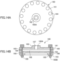
- the runner 160 has a smaller outside diameter than the runner 60. That is, the runner 160 is a runner for injecting a resin into a rotor core having a smaller diameter than the rotor core 1A in terms of the positions of the hole portions (that is, the outside diameter).
- the runner 160 similarly to the runner 60, the runner 160 includes a disc-shaped body 161, a shaft-shaped upper shaft portion 162 extending upward from the center of the body 161, a plurality of branch nozzles 163 extending downward from the lower outer periphery of the body 161, and a plurality of stop valves 164 disposed in the respective branch nozzles 163.
- a charging channel 167 whose upper end serves as a resin charging port 160A is formed inside the runner 160 in the vertical direction along a central axis of the upper shaft portion 162 and the disc shape of the body 161.
- Branch channels 168 that branch from the charging channel 167 toward the branch nozzles 163 are formed inside the body 161.
- Injection channels 169 are formed to extend downward from the circumferential ends of the branch channels 168. Ejection ports 160B serving as the second ejection ports are formed at the lower ends of the injection channels 169.
- the runner 160 includes a heating wire 165 disposed so as to surround the runner 160 in the circumferential direction, and a coolant channel 166 similarly disposed so as to surround the runner 160 in the circumferential direction.
- the runner 160 is structured such that, when the center of the charging channel 167 in the axial direction is defined as a central axis, the radius from the charging port 160A to the ejection port 160B is different from, that is, smaller than the radius from the charging port 60A to the ejection port 60B of the runner 60.
- the upper shaft portion 162 has the same shape as the upper shaft portion 62 of the runner 60 so as to be attachable to and detachable from the attachment hole 52a of the upper plate 52 of the table portion 50. As shown in FIG. 15 , the runner 160 can detachably be attached to the upper plate 52 by fitting the upper shaft portion 162 to the attachment hole 52a of the upper plate 52.
- the runner 160 is described as having the ejection ports 160B positioned with a small diameter as compared with the runner 60, the runner 160 may conversely be a runner having a large radius from the charging port to the ejection port, that is, a runner for injecting a resin into a rotor core having a large radius to the hole portion.
- the rotor manufacturing apparatus (30) described above is a rotor manufacturing apparatus (30) configured to manufacture a rotor (1) of a rotary electric machine, the rotor manufacturing apparatus (30) including:
- the rotors 1 with different hole positions can be manufactured by the same resin injector 40 while eliminating the need to change the resin injector. Thus, the cost can be reduced.
- the rotor manufacturing apparatus (30) further includes
- the runner 60 (160) can be replaced easily.
- the resin can be injected into all the hole portions 1B of the rotor core 1A even if the branch nozzles 63 (163) having the ejection ports 60B (160B) cannot be brought close to each other and as many ejection ports 60B (160B) as the first number of the hole portions 1B cannot be prepared.
- the rotor manufacturing apparatus (30) further includes:
- the temperature control for melting the resin in the resin injector 40 and the temperature control for dealing with the temperature change caused by the disturbance in the runner 60 (160) can be performed independently. Since the rotor core 1A placed on the placement table 55 is moved relative to the runner 60 (160), there is no need to move the runner 60 (160) and the resin injector 40 at least in the resin injection step S6. There is no need to move the temperature control device 81 and the temperature control device 82 as well.
- the runner includes a first runner (60), and a second runner (160) structured such that a radius from the charging port (160A) to the second ejection ports (160B) is different from a radius from the charging port (60A) to the second ejection ports (60B) of the first runner (60).
- the resin can be injected only by replacing the runner.
- the stop valve 43 can freely perform and stop the resin ejection from the runner 60 (160) to the hole portions 1B of the rotor core 1A.
- the stop valves 64 (164) can freely perform and stop the resin ejection from the resin injector 40 to the runner 60 (160). In particular, the resin can be stopped when the runner 60 (160) is replaced.
- the runner (60, 160) is formed such that an amount of the resin to fill a part from the charging port (60A, 160A) to the plurality of second ejection ports (60B, 160B) is larger than an amount of the resin to be ejected at one time from the plurality of second ejection ports (60B, 160B) toward the hole portions (1B).
- the temperature of the resin to be injected into the hole portions 1B of the rotor core 1A can be kept at an appropriate temperature inside the runner 60 (160).
- a rotor manufacturing method is a rotor manufacturing method for manufacturing a rotor (1) of a rotary electric machine by disposing magnet members (1M) in hole portions (1B) of a rotor core (1A) and injecting and curing a resin to fix the magnet members (1M) to the rotor core (1A), the rotor manufacturing method including:
- the rotors 1 with different hole positions can be manufactured by the same resin injector 40 while eliminating the need to change the resin injector. Thus, the cost can be reduced.
- the resin can be injected into all the hole portions 1B of the rotor core 1A even if the branch nozzles 63 having the ejection ports 60B cannot be brought close to each other and as many ejection ports 60B as the first number of the hole portions 1B cannot be prepared.
- the resin can be injected only by replacing the runner.
- the holding jig 10 broadly includes the lower plate 11, the pressing plate 12, the upper plate 13, and the coil springs 23.
- the present invention is not limited to this case. Any structure may be used as long as the rotor core 1A can be interposed and held in the stacking direction.
- Preheating may be performed approximately to the melting start temperature in the heating step S4, and main heating may be performed to a processing temperature or higher in the magnet fixing step S7 after the resin injection.
- the holding jig 10 is also cooled by the cooling device in the cooling step S9.
- the holding jig 10 may be cooled naturally.
- many holding jigs 10 may be prepared so that the natural cooling suffices even if the holding jigs 10 are reused.
- the present invention is not limited to this case.
- the cooling period can be shortened by detaching the holding jig 10 even if the rotor core 1A is cooled naturally.
- the injection hole 12c in which the resin plate portion 99a and the conical portion 99b are formed is formed in the pressing plate 12 of the holding jig 10 serving as an abutment member.
- the present invention is not limited to this case.
- the holding jig 10 is not used, such as a case where the resin is injected while holding the rotor core 1A by another method instead of holding the rotor core 1A by using the holding jig 10.
- the injection hole in which the resin plate portion 99a and the conical portion 99b are formed may be formed in a different plate or the like that abuts against the rotor core 1A.
- the resin plate portion 99a and the conical portion 99b are formed at the injection hole 12c, but these shapes may be any shapes. That is, the shape formed so as to protrude from the upper surface of the rotor core 1A at the enlarged opening portion may be, for example, a triangular pyramid shape, a square pyramid shape, a conical shape, or a hemispherical shape instead of the plate shape.
- the shape formed at the tapered portion may be, for example, a triangular pyramid shape, a square pyramid shape, a conical shape, or a hemispherical shape instead of the conical shape.
- the runner 60 is detachably supported on the table portion 50.
- the runner 60 may directly be fixed to and supported on, for example, the nozzle portion 42 of the resin injector 40. Further, the runner 60 may be supported on a member other than the table portion 50.
- the rotor core 1A may be moved in any direction depending on the orientations of the resin injector 40 and the runner 60. That is, any structure may be used as long as the resin injector 40 and the runner 60 are not moved at least in the resin injection step S6.
- the temperature control device 81 controls the temperature of the resin injector 40 and the temperature control device 82 controls the temperature of the runner 60.
- the present invention is not limited to this case.
- a single temperature control device may perform the temperature control.
- more temperature control devices may be used to subdivide the temperature control on the resin injector 40 and the runner 60.
- the resin injector 40 has the same structure as a so-called compression molding resin injector that compresses and ejects a molten resin.
- the resin injector 40 may be a so-called transfer molding resin injector that puts a preheated resin material into a transfer chamber and then ejects the resin material.
- the rotor manufacturing apparatus and the rotor manufacturing method can be used when manufacturing a rotor of a rotary electric machine, and are particularly suitable for use in a case requiring the manufacture of rotors with different hole positions using the same resin injector.
Landscapes
- Engineering & Computer Science (AREA)
- Manufacturing & Machinery (AREA)
- Power Engineering (AREA)
- Mechanical Engineering (AREA)
- Manufacture Of Motors, Generators (AREA)
- Permanent Field Magnets Of Synchronous Machinery (AREA)
- Moulds For Moulding Plastics Or The Like (AREA)
- Injection Moulding Of Plastics Or The Like (AREA)
Abstract
Description
- The present technology relates to a rotor manufacturing apparatus and a rotor manufacturing method for manufacturing a rotor of a rotary electric machine.
- In general, an interior permanent magnet (IPM) motor is used as a rotary electric machine mounted on a vehicle such as a hybrid vehicle or an electric vehicle. When manufacturing a rotor of such a rotary electric machine, a rotor core (stacked iron core) is formed by stacking stacked steel sheets with holes, magnets are inserted into the holes, and the magnets are fixed to the rotor core by injecting a thermosetting resin into the holes and heating the thermosetting resin, thereby obtaining a rotor having the magnets embedded in the rotor core. When injecting the resin into the holes of the rotor core in this manner, the holes in the rotor core in which the magnets are disposed are aligned with nozzles of a resin injector, and then the resin is injected directly into the holes from the nozzles (see Patent Document 1).
- Patent Document 1:
Japanese Unexamined Patent Application Publication No. 2012-228032 JP 2012-228032 A - In recent years, a variety of rotary electric machines have been used in hybrid vehicles, electric vehicles, and the like, and the shapes of the rotors of the rotary electric machines, in particular, the positions of the holes in which the magnets are disposed differ from product to product. If one resin injection apparatus handles the different rotor shapes, however, the resin injector needs to be changed greatly to change, for example, the positions of the nozzles, which leads to a problem of hindrance to cost reduction.
- Therefore, it is an object to provide a rotor manufacturing apparatus and a rotor manufacturing method capable of manufacturing rotors with different hole positions by using the same resin injector while eliminating the need to change the resin injector.
- The rotor manufacturing apparatus is
a rotor manufacturing apparatus configured to manufacture a rotor of a rotary electric machine. - The rotor manufacturing apparatus includes:
- a resin injector having a first ejection port for ejecting a resin; and
- a runner having a charging port connectable to the first ejection port, and a plurality of second ejection ports communicating with the charging port and disposed at positions associated with hole portions of a rotor core where magnet members are disposed.
- The rotor manufacturing method is
a rotor manufacturing method for manufacturing a rotor of a rotary electric machine by disposing magnet members in hole portions of a rotor core and injecting and curing a resin to fix the magnet members to the rotor core. - The rotor manufacturing method includes:
- an injection apparatus placement step for placing the rotor core on a placement portion; and
- a resin injection step for attaching, to the placement portion, a runner attachable to and detachable from the placement portion, connecting, to a charging port of the runner, a first ejection port for ejecting the resin in a resin injector, and injecting the resin from the resin injector into the hole portions of the rotor core through a plurality of second ejection ports disposed at positions on the runner that are associated with the hole portions of the rotor core.
- By replacing the runner in conformity to the shape of the rotor core, the rotors with different hole positions can be manufactured by the same resin injector while eliminating the need to change the resin injector. Thus, the cost can be reduced.
-
- [
FIG. 1] FIG. 1 is a flowchart showing steps of a rotor manufacturing method according to the present embodiment. - [
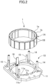
FIG. 2] FIG. 2 is a perspective view showing a rotor core and a lower plate of a holding jig. - [
FIG. 3] FIG. 3 is a perspective view showing a state in which the rotor core is placed on the lower plate of the holding jig. - [
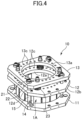
FIG. 4] FIG. 4 is a perspective view showing a state in which the holding jig is attached to the rotor core. - [
FIG. 5] FIG. 5 is a sectional view showing a state in which an injector is separated from a rotor placement portion in an injection apparatus. - [
FIG. 6] FIG. 6 is a sectional view showing a state in which an injection nozzle is attached to the rotor placement portion in the injection apparatus. - [
FIG. 7] FIG. 7 is a sectional view showing a state in which the rotor core is placed on the rotor placement portion in the injection apparatus. - [
FIG. 8] FIG. 8 is a sectional view showing a state in which the injection apparatus injects a resin into the rotor core. - [
FIG. 9] FIG. 9 is a sectional view showing a state in which the rotor core into which the injection apparatus has injected the resin is detached from the rotor placement portion. - [
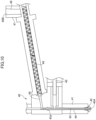
FIG. 10] FIG. 10 is a sectional view showing the injector in the injection apparatus. - [
FIG. 11A] FIG. 11A is a top view showing the injection nozzle. - [
FIG. 11B] FIG. 11B is a sectional view showing the injection nozzle. - [
FIG. 11C] FIG. 11C is a top view showing a positional relationship between the rotor core and the injection nozzle. - [
FIG. 12A] FIG. 12A is an enlarged top view showing a positional relationship between a hole portion of the rotor core and each of a nozzle and a gate of the injection nozzle, and a state of the injected resin. - [
FIG. 12B] FIG. 12B is an enlarged sectional view showing the hole portion of the rotor core and the nozzle and the gate of the injection nozzle. - [
FIG. 12C] FIG. 12C is an enlarged sectional view showing the rotor core and the state of the resin after resin injection. - [
FIG. 13A] FIG. 13A is a schematic sectional view illustrating the shapes of and the positional relationship between the hole portion of the rotor core and each of the nozzle and the gate of the injection nozzle. - [
FIG. 13B] FIG. 13B is a schematic sectional view illustrating separation of the resin at the gate after the resin injection. - [
FIG. 14A] FIG. 14A is a top view showing another injection nozzle for replacement. - [
FIG. 14B] FIG. 14B is a sectional view showing the other injection nozzle for replacement. - [
FIG. 15] FIG. 15 is a sectional view showing a state in which the other injection nozzle for replacement is attached to the rotor placement portion in the injection apparatus. - The present embodiment will be described below with reference to the drawings.
- First, brief description will be given of the structure of a rotor in, for example, a drive motor (rotary electric machine) of a hybrid drive system or an electric vehicle. The drive motor broadly includes a stator (stationary element) and a rotor 1 (rotary element). As shown in
FIG. 2 , therotor 1 includes arotor core 1A formed by stacking stackedsteel sheets 1a each having a plurality ofholes 1b formed by press working or the like. A plurality ofhole portions 1B is formed in therotor core 1A by stacking the stackedsteel sheets 1a in a stacking direction with theholes 1b aligned in phase. As shown inFIG. 3 ,magnets 1M serving as magnet members are inserted and disposed in thehole portions 1B, respectively. In this state, themagnets 1M are fixed to therespective hole portions 1B with a resin, thereby forming therotor 1 having themagnets 1M embedded in therotor core 1A. - Next, an outline of a rotor manufacturing method according to the present embodiment will be described. As shown in
FIG. 1 , the rotor manufacturing method includes a steel sheet stacking step S1 for stacking the stackedsteel sheets 1a to form therotor core 1A, a magnet disposing step S2 for inserting and disposing themagnets 1M in thehole portions 1B of therotor core 1A, and a jig attaching step S3 for attaching a holdingjig 10 to therotor core 1A. The rotor manufacturing method further includes a heating step S4 for heating therotor core 1A, an injection apparatus placement step S5 for placing therotor core 1A on aresin injection apparatus 30 for injecting a resin, and a resin injection step S6 for causing theresin injection apparatus 30 to inject the resin into thehole portions 1B of therotor core 1A. The rotor manufacturing method further includes a magnet fixing step S7 for fixing themagnets 1M to therotor core 1A by curing the injected resin, a jig detaching step S8 for detaching the holdingjig 10 from therotor core 1A, and a cooling step S9 for cooling therotor core 1A. These steps are sequentially performed in a factory line while moving therotor core 1A by, for example, a belt conveyor. When stacking the stackedsteel sheets 1a in the steel sheet stacking step S1 described later, an operator performs adjustment. In the other steps, the conveyance of therotor core 1A, the attachment and detachment of the holdingjig 10, and the like are performed by factory equipment such as articulated robots. - First, details of the steel sheet stacking
step S 1 will be described with reference toFIG. 2 . As shown inFIG. 2 , therotor core 1A is formed, for example, by press working into a hollow disc shape that is point-symmetrical about the center. Therotor core 1A is formed by stacking the stackedsteel sheets 1a each having the plurality ofholes 1b while sequentially laying the stackedsteel sheets 1a on anupper surface 11b of alower plate 11 of the holdingjig 10 detailed later. The stackedsteel sheets 1a have a slight tolerance. Therefore, the operator stacks the stackedsteel sheets 1a while adjusting the phase in a circumferential direction of the hollow disc shape. Thus, the stackedsteel sheets 1a are stacked so that the uppermost stackedsteel sheet 1a has less inclination with respect to a plane orthogonal to the stacking direction (that is, a horizontal direction). The stackedsteel sheets 1a may be stacked on theupper surface 11b of thelower plate 11 of the holdingjig 10 as described above, or may be stacked at a different place to form therotor core 1A and then placed on theupper surface 11b of thelower plate 11 of the holdingjig 10. - The
lower plate 11 of the holdingjig 10 is a hollow plate-shaped member having ahole 11a formed at the center. Asupport plate 16 for positioning and supporting therotor core 1A is fixed to thehole 11a.First shafts 14 andsecond shafts 15 shorter than thefirst shafts 14 are provided upright, for example, at four positions on thelower plate 11. Therefore, when therotor core 1A is placed on theupper surface 11b of thelower plate 11, thesupport plate 16 abuts against a part of the inner peripheral surface of therotor core 1A, and thesecond shafts 15 abut against a part of the outer peripheral surface. Thus, therotor core 1A is supported on thelower plate 11 while restricting horizontal movement and determining the relative positions of thelower plate 11 and therotor core 1A. Thelower plate 11 has a plurality ofair holes 11c formed through thelower plate 11 at positions overlapping the positions of thehole portions 1B in the stacking direction when therotor core 1A is placed, and serving as air vent holes during resin injection described later. - Next, details of the magnet disposing step S2 will be described with reference to
FIG. 3 . As shown inFIG. 3 , therotor core 1A placed on thelower plate 11 of the holdingjig 10 has the plurality ofhole portions 1B formed by stacking theholes 1b of the stackedsteel sheets 1a. Themagnets 1M are inserted and disposed in therespective hole portions 1B. Therotor core 1A shown inFIG. 3 is described as a rotor core in which themagnets 1M are disposed with their longitudinal directions corresponding to the circumferential direction. In the present embodiment, as shown inFIG. 11C , it is assumed that the longitudinal direction of themagnet 1M is inclined with respect to the circumferential direction and twomagnets 1M are disposed so as to form a V shape when viewed from above. In general, the magnet is demagnetized when heated. Therefore, themagnet 1M at this stage is a magnet material before magnetization. - Next, details of the jig attaching step S3 will be described with reference to
FIG. 4 . First, the structure of the holdingjig 10 will be described. - As shown in
FIG. 4 , the holdingjig 10 is broadly provided such that thelower plate 11, apressing plate 12, and anupper plate 13 are sequentially disposed substantially in parallel in a vertical direction. Therotor core 1A is placed on theupper surface 11b of thelower plate 11 as described above, and thepressing plate 12 is placed above therotor core 1A so that alower surface 12b of thepressing plate 12 abuts against therotor core 1A. Thepressing plate 12 is a hollow plate-shaped member having ahole 12a formed at the center. As detailed later, a plurality ofinjection holes 12c for injecting a resin is formed through thepressing plate 12 so as to be positioned above thehole portions 1B of therotor core 1A. Thepressing plate 12 has a plurality of throughholes 12d through which thesecond shafts 15 described above can pass. - The
upper plate 13 is a hollow plate-shaped member having ahole 13a formed at the center, and is fastened to the upper ends of thesecond shafts 15 withbolts 21. Coil springs 23 are compressed between thepressing plate 12 and theupper plate 13. A support shaft (not shown) is disposed on an inner side of eachcoil spring 23 and fixed to theupper plate 13 with abolt 22, thereby positioning and supporting thecoil spring 23. In the holdingjig 10 structured as described above, therotor core 1A is held under pressure between thelower plate 11 and thepressing plate 12 pressed by the coil springs 23 from theupper plate 13. As a result, the plurality of stackedsteel sheets 1a of therotor core 1A is pressed in the stacking direction and held in contact with each other with as small a gap as possible in the stacking direction. The upper ends of thefirst shafts 14 are formed so as to face the lower surface of thepressing plate 12. Thepressing plate 12 abuts against the upper ends while being pressed downward by the coil springs 23 so as not to crush therotor core 1A in the stacking direction. - When the holding
jig 10 structured as described above is attached to therotor core 1A in the jig attaching step S3, therotor core 1A is placed on theupper surface 11b of thelower plate 11, thepressing plate 12 is placed above therotor core 1A with thesecond shafts 15 passing through the through holes 15d, theupper plate 13 is placed with the coil springs 23 interposed between theupper plate 13 and thepressing plate 12, and thesecond shafts 15 and theupper plate 13 are fastened with thebolts 21. As a result, the holdingjig 10 that holds therotor core 1A while pressing it in the stacking direction is attached to therotor core 1A. - Next, details of the heating step S4 will be described. In the present embodiment, the resin for fixing the
magnets 1M in thehole portions 1B of therotor core 1A is, for example, a thermosetting resin material that has a melting start temperature of 60°C, and a curing start temperature of 120°C, and is solid at room temperature. When the temperature of therotor core 1A is lower than the melting start temperature, the resin may be solidified during the resin injection in the resin injection step S6 described later. Therefore, thehole portions 1B may be filled with the resin insufficiently. Thus, the temperature of therotor core 1A needs to be equal to or higher than the melting start temperature when the resin is injected. In the present embodiment, when the resin is injected into thehole portion 1B, the resin may leak from a small gap between thestacked steel sheets 1a. By setting the temperature of therotor core 1A to be equal to or higher than the curing start temperature when the resin is injected, curing is started from the resin in contact with thehole portion 1B. Thus, it is possible to prevent the resin from leaking between thestacked steel sheets 1a. - From the above background, in the heating step S4, the
rotor core 1A held by the holding jig 10 (to which the holdingjig 10 is attached) is put into a heating device such as a high-frequency heater together with the holdingjig 10 to heat therotor core 1A to the melting start temperature of the resin or higher, preferably the curing start temperature or higher. In the present embodiment, therotor core 1A is heated to, for example, about 150°C in the heating step S4. - Next, details of the injection apparatus placement step S5 for placing the
rotor core 1A held by the holdingjig 10 on theresin injection apparatus 30 for injecting the resin will be described with reference toFIGS. 5 ,6 ,7 ,8 , and10 . First, description will be given of the structure of theresin injection apparatus 30 serving as a rotor manufacturing apparatus for manufacturing a rotor. - As shown in
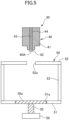
FIG. 6 , theresin injection apparatus 30 includes, in a narrow sense, aresin injector 40 and atable portion 50 serving as a placement portion on which therotor core 1A is placed. Arunner 60 is disposed in thetable portion 50 to structure, in a broad sense, theresin injection apparatus 30 for injecting the resin into therotor core 1A. As shown inFIG. 10 , theresin injector 40 includes a chargingportion 47 having aresin charging hole 48 whose upper end serves as a resinmaterial charging port 40B for charging a solid resin, ascrew 46 for sending the resin charged from the resinmaterial charging port 40B to achannel 49 while melting and agitating the resin, atubular portion 41 having achannel 44 that communicates with thechannel 49, anozzle portion 42 fixed to the lower end of thetubular portion 41 and having anejection port 40A at the lower end to serve as a first ejection port for ejecting the resin, astop valve 43 serving as a first valve that passes or blocks the resin flow from thechannel 49 to thechannel 44 by an on-offvalve 43a, and aplunger 45 for ejecting the resin in thechannel 44 from theejection port 40A. As shown inFIG. 8 , a temperature control device 81 (Temp Control Device) serving as a first temperature control device capable of heating or cooling by, for example, a heating wire or coolant supply is attached to theresin injector 40. Thetemperature control device 81 controls the temperature of the resin at, for example, about 80°C equal to or higher than the melting start temperature and lower than the curing start temperature to keep the molten state of the resin between the resinmaterial charging port 40B and theejection port 40A. In particular, thetemperature control device 81 heats thescrew 46 to melt the resin that has been charged into the resinmaterial charging port 40B and is solid at room temperature and keep the molten state of the resin. - As shown in
FIG. 6 , thetable portion 50 includes alower plate 51 disposed on a lower side,side walls 53 fixed to the side ends of thelower plate 51, and anupper plate 52 supported by theside walls 53, disposed in parallel above thelower plate 51 to face thelower plate 51, and serving as a support portion for supporting therunner 60. Ahole 51a is formed in the central portion of thelower plate 51. Thetable portion 50 includes a placement table 55 formed in conformity to the shape of thehole 51a and having anupper surface 55a serving as a table on which thelower plate 11 of the holdingjig 10 is placed, and adriving device 59 serving as a driving unit for controlling the placement table 55 to ascend or descend and to rotate. Although illustration is omitted, theupper surface 55a of the placement table 55 has a projection, and the lower surface of thelower plate 11 of the holdingjig 10 has a recess. By fitting the projection and the recess when the holdingjig 10 is placed on the placement table 55, the position of the holdingjig 10 relative to the placement table 55 is regulated in the rotating direction, that is, the positions of the holdingjig 10 and therotor core 1A in the rotating direction are controlled by the rotation of the placement table 55. - As shown in
FIG. 5 , anattachment hole 52a is formed in theupper plate 52 of thetable portion 50. Therunner 60 is detachably attached by fitting anupper shaft portion 62 of therunner 60 to theattachment hole 52a. Therunner 60 broadly includes a chargingport 60A fitted to theejection port 40A of theresin injector 40, and a plurality ofejection ports 60B formed inbranch nozzles 63 to branch and eject the resin charged from the chargingport 60A. Details of the structure of therunner 60 will be described later. - In the injection apparatus placement step S5 for placing the
rotor core 1A to which the holdingjig 10 is attached on theresin injection apparatus 30 structured as described above, theresin injector 40 is first separated from thetable portion 50 as shown inFIG. 5 , and therunner 60 is attached to theupper plate 52 by fitting theupper shaft portion 62 of therunner 60 detailed later to theattachment hole 52a of theupper plate 52 as shown inFIG. 6 in a state in which the placement table 55 descends with theupper surface 55a flush with thelower plate 51. In this state, therotor core 1A to which the holdingjig 10 is attached is placed on the placement table 55 as shown inFIG. 7 . At this time, therotor core 1A is fixed so as to be immovable in the rotating direction by fitting the projection (not shown) provided to theupper surface 55a of the placement table 55 to the recess (not shown) provided to thelower plate 11 of the holdingjig 10 as described above. As shown inFIG. 8 , the placement table 55 is caused to ascend by the drivingdevice 59, thebranch nozzles 63 having theejection ports 60B detailed later are inserted into the throughholes 13c of theupper plate 13 and the injection holes 12c of thepressing plate 12 that are formed in the holdingjig 10, and the tips of thebranch nozzles 63 are set in pressure contact with the injection holes 12c. Thus, therotor core 1A is placed on theresin injection apparatus 30. - Next, details of the resin injection step S6 will be described with reference to
FIGS. 8 ,12A, 12B, and 12C . First, description will be given of a positional relationship between theinjection hole 12c of thepressing plate 12 of the holdingjig 10 and thehole portion 1B of therotor core 1A and the shape of theinjection hole 12c.FIG. 12B shows a cross section viewed along arrows A-A inFIG. 12A. FIG. 12C shows a state in which the holdingjig 10 is detached from therotor core 1A at the same position as that inFIG. 12B . - In the state in which the holding
jig 10 is attached to therotor core 1A, theinjection hole 12c of thepressing plate 12 is positioned to at least partially overlap thehole portion 1B of therotor core 1A as shown inFIG. 12A . Specifically, the center of theinjection hole 12c is positioned on a radially inner side of therotor core 1A with respect to thehole portion 1B. When the resin is injected into thehole portion 1B, themagnet 1M is pressed to an outer peripheral side by the pressure of the resin. As a result, themagnet 1M is brought closer to a radially outer side of therotor core 1A. That is, when therotor core 1A is attached to the stator as the rotary electric machine, themagnet 1M is brought as close to the stator as possible, thereby increasing the magnetic force and improving the output and efficiency of the rotary electric machine. - As shown in
FIG. 12B , theinjection hole 12c of thepressing plate 12 of the holdingjig 10 includes a first inclined surface 12ca that has an inclined shape gradually decreasing in bore diameter so that a conicalinclined surface 63a at the tip of thebranch nozzle 63 of therunner 60 can be fitted in pressure contact, and that is sealed when fitted, a second inclined surface 12cb that is disposed below the first inclined surface 12ca (close to therotor core 1A) and has a tapered shape with decreasing bore diameter toward therotor core 1A in a penetrating direction of theinjection hole 12c by being inclined at an acute angle θ with respect to the center of theinjection hole 12c, a step portion 12cc that is formed between the first inclined surface 12ca and the second inclined surface 12cb and prevents thebranch nozzle 63 from entering the second inclined surface 12cb, a small-diameter portion 12ce that is formed at the lower tip of the second inclined surface 12cb and functions as a throttle portion with the smallest bore diameter, and an enlarged opening portion 12cd that is wider than the small-diameter portion 12ce in the horizontal direction (direction orthogonal to the penetrating direction) below the small-diameter portion 12ce and serves as an opening portion of theinjection hole 12c. - In the present embodiment, the angle θ of the second inclined surface 12cb is set to, for example, 30°, but may be any acute angle, that is, may be larger than 0° and smaller than 45°. In the present embodiment, as shown in
FIG. 12A , the enlarged opening portion 12cd has a rectangular shape that extends in the horizontal direction at a position including the small-diameter portion 12ce when viewed in the vertical direction, but is not limited to this shape, and may have any shape such as a circular shape, an elliptical shape, or an oblong shape in sectional view as long as the sectional area in the horizontal direction is larger than that of the small-diameter portion 12ce. The enlarged opening portion 12cd is positioned across an upper surface 1Aa and thehole portion 1B of therotor core 1A in a state in which thepressing plate 12 abuts against the upper surface 1Aa of therotor core 1A. The small-diameter portion 12ce has a diameter of, for example, about 1 mm to 5 mm, and the enlarged opening portion 12cd has a vertical thickness of, for example, about 0.5 mm. - In the resin injection step S6 for injecting the resin into the
hole portion 1B of therotor core 1A from theinjection hole 12c of thepressing plate 12 of the holdingjig 10 structured as described above, as shown inFIG. 8 , in theresin injector 40 of theresin injection apparatus 30, thestop valve 43 is opened and the resin in thechannel 44 is pressed by the plunger 45 (seeFIG. 10 ). Therefore, the resin is ejected from theejection port 40A into the chargingport 60A of therunner 60, and is ejected into eachhole portion 1B from eachejection port 60B of therunner 60. Thus, the resin fills the periphery of themagnet 1M while pressing themagnet 1M toward the radially outer side of therotor core 1A. - At this time, air inside the
hole portion 1B escapes from theair hole 11c of thelower plate 11 of the holdingjig 10, and the resin fills thehole portion 1B without a gap. Since therotor core 1A is heated to a temperature higher than the curing start temperature of the resin as described above, the resin filling thehole portion 1B starts to be cured from a portion in contact with the side surface of thehole portion 1B, thereby preventing the resin from leaking from the gap between thestacked steel sheets 1a. As shown inFIG. 12C , a fillingresin 99 fills thehole portion 1B up to its opening, and further fills the enlarged opening portion 12cd while causing air to slightly escape into the enlarged opening portion 12cd. A rectangular plate-shapedresin plate portion 99a is formed across thehole portion 1B and the upper surface 1Aa of therotor core 1A. The function of theplate portion 99a will be described later in detail in the jig detaching step S8. - Next, details of the magnet fixing step S7 will be described. When the resin injection step S6 is finished, as shown in
FIG. 9 , therotor core 1A to which the holdingjig 10 is attached is detached from the placement table 55 of theresin injection apparatus 30. That is, therotor core 1A is taken out from theresin injection apparatus 30. In this state, therotor core 1A is heated by a heating device (not shown) with the holdingjig 10 attached so as to keep the temperature of therotor core 1A at, for example, about 150°Cequal to or higher than the curing start temperature of the resin. That is, the resin filling thehole portion 1B of therotor core 1A starts to be cured from the portion in contact with therotor core 1A during the injection as described above, but there is a portion that is not completely cured inside thehole portion 1B. Therefore, in the magnet fixing step S7, the heated state is kept and the temperature of the resin in thehole portion 1B is kept at the curing start temperature or higher for a predetermined period until the resin is completely cured. As a result, themagnet 1M is completely fixed to thehole portion 1B of therotor core 1A by the resin. In the present embodiment, description is given of the case where therotor core 1A is heated by the heating device to the temperature of, for example, about 150°Cin the magnet fixing step S7. Therotor core 1A may be heated to a higher temperature (for example, about 170°C) to accelerate the resin curing. - When the resin curing is completed in the magnet fixing step S7 as described above, the
rotor core 1A is completed as therotor 1. Then, a rotor shaft and the like are attached to therotor 1 to form a rotor with a shaft, which constitutes a broadly defined rotor as a component of the rotary electric machine. - In the present embodiment, the heating step S4 and the magnet fixing step S7 are separately described. As described above, the heating of the
rotor core 1A is started in the heating step S4, and the temperature of therotor core 1A is kept at the curing start temperature of the resin or higher until the magnet fixing step S7. Therefore, the heating step in a broad sense continues up to the heating step S4, the injection apparatus placement step S5, the resin injection step S6, and the magnet fixing step S7. In other words, the heating step S4 is also the step of fixing themagnets 1M to therotor core 1A because the heating is performed to cure the resin even before the resin is injected. - Next, details of the jig detaching step S8 will be described. When the
magnets 1M are completely fixed to thehole portions 1B of therotor core 1A by curing the resin in the magnet fixing step S7, the holdingjig 10 is detached from therotor core 1A (rotor 1). That is, the holdingjig 10 is detached from therotor core 1A in the order opposite to the order of attachment of the holdingjig 10 to therotor core 1A in the jig attaching step S3. Specifically, thebolts 21 shown inFIG. 4 are unfastened to detach theupper plate 13 and the coil springs 23. Then, thepressing plate 12 is detached from thelower plate 11 by being pulled out from thesecond shafts 15 to achieve the state shown inFIG. 3 . Lastly, therotor core 1A is taken out from thelower plate 11 upward. Thus, the jig detaching step S8 is finished. - Separation of the resin at the
injection hole 12c of thepressing plate 12 of the holdingjig 10 will be described with reference toFIGS. 13A and 13B. FIGS. 13A and 13B are schematic diagrams for facilitating the description. The detailed shape of theinjection hole 12c is more exactly shown inFIG. 12B . - In general, when a nozzle is moved away after a resin is ejected from the nozzle, the uncured resin may extend like a thread to form a so-called burr. In order that the burr does not come into contact with the surrounding components inside the rotary electric machine or does not fall into the rotary electric machine, it is necessary to perform a deburring process for cleanly removing the burr. However, such a deburring process requires dedicated equipment. Further, it is difficult to automate the deburring process. Therefore, it is necessary to assign an operator. Thus, the cost may increase. In view of this, the present embodiment has a feature in the shape of the
injection hole 12c so that the deburring process becomes unnecessary. - In the resin injection step S6 described above, the resin is injected into the
hole portion 1B of therotor core 1A in a state in which thebranch nozzle 63 of therunner 60 is inserted in pressure contact with theinjection hole 12c of thepressing plate 12 as shown inFIG. 13A . At this time, thebranch nozzle 63 does not enter the second inclined surface 12cb due to the step portion 12cc. Therefore, theejection port 60B is positioned on the second inclined surface 12cb side in the penetrating direction with respect to the small-diameter portion 12ce of theinjection hole 12c. Theresin 99 particularly fills portions located below theejection port 60B of thebranch nozzle 63 and surrounded by the second inclined surface 12cb and by the enlarged opening portion 12cd to form, as shown inFIG. 13B , theplate portion 99a (seeFIG. 12C ) by the enlarged opening portion 12cd and aconical portion 99b having a conical shape by the second inclined surface 12cb so as to be connected to theplate portion 99a. At this time, a narrow constriction is formed in the horizontal direction between theresin plate portion 99a and theconical portion 99b due to the small-diameter portion 12ce. Although theejection port 60B is located at the end of the first inclined surface 12ca in the present embodiment, it may enter the second inclined surface 12cb halfway. - If the
pressing plate 12 is separated from therotor core 1A when thepressing plate 12 is detached from the upper surface 1Aa of therotor core 1A in the jig detaching step S8, the second inclined surface 12cb pulls theconical portion 99b upward while grabbing it. Thus, it is possible to break theconical portion 99b by concentrating a shear stress on the constricted part having low rigidity. When thepressing plate 12 is pulled upward, theconical portion 99b pulls theplate portion 99a. As shown inFIG. 12A , theplate portion 99a is formed across thehole portion 1B and the upper surface 1Aa of therotor core 1A so as to adhere to therotor core 1A in an area equal to or larger than the sectional area of the small-diameter portion 12ce. Therefore, the majority of the tensile stress is received by the upper surface 1Aa of therotor core 1A. Thus, it is possible to prevent influence on the positional accuracy of themagnet 1M by pulling themagnet 1M via theresin 99 in thehole portion 1B. Regarding a broken portion 99bx of theconical portion 99b and a broken portion 99ax of theplate portion 99a shown inFIG. 13B , the broken portion 99ax is a recess and the broken portion 99bx is a projection. Depending on the temperature or the degree of tensile strength, the broken portion 99ax and the broken portion 99bx may be substantially smooth or the projection and recess may be reversed. When thebranch nozzle 63 is separated from theinjection hole 12c, the resin may extend like a thread from theejection port 60B to form a burr. The burr is formed at an upper part of theconical portion 99b and theconical portion 99b is finally discarded. Therefore, even if the burr is formed at that part, the burr does not remain on therotor core 1A. - As described above, when the
pressing plate 12 of the holdingjig 10 is detached from therotor core 1A in the jig detaching step S8, theconical portion 99b can cleanly be broken off theresin plate portion 99a. For example, the step for the deburring process can be made unnecessary. Since the holdingjig 10 is detached before the cooling in the cooling step S9 described later, the separation between thelower plate 11 and the resin in thehole portion 1B of therotor core 1A and between thepressing plate 12 and each of theresin plate portion 99a and thehole portion 1B can be performed in a high-temperature and uncooled state of the resin. That is, the separation can be performed before the adhesion is strengthened by the cooling of the resin. Therefore, the holdingjig 10 can be detached easily. Theconical portion 99b remaining in theinjection hole 12c of thepressing plate 12 is removed and discarded by pushing it out with a pin or the like. Then, the components of the holdingjig 10 including theair holes 11c of thelower plate 11 are cleaned with a brush or the like, and are used again for manufacturing thenext rotor core 1A. - Lastly, details of the cooling step S9 will be described. After the holding
jig 10 is detached from therotor core 1A (rotor 1) in the jig detaching step S8 as described above, therotor core 1A from which the holdingjig 10 is detached and the holdingjig 10 detached from therotor core 1A are put into a cooling device together and individually cooled inside the cooling device. That is, when the holdingjig 10 is attached to therotor core 1A, thelower plate 11 and thepressing plate 12 are particularly in contact with and cover both the upper and lower surfaces of therotor core 1A. By detaching the holdingjig 10, the exposed surface area of therotor core 1A is larger than that before the detachment. Thus, the cooling efficiency increases. Since the holdingjig 10 also has a large heat capacity, the holdingjig 10 and therotor core 1A are not easily cooled due to the large heat capacity in the state in which the holdingjig 10 is attached to therotor core 1A. By separating the holdingjig 10 and therotor core 1A, the cooling efficiency increases because each heat capacity decreases. As a result, it is possible to shorten the cooling period of therotor core 1A and to shorten the cooling period of the holdingjig 10 as well. - Next, the detailed structure of the
runner 60 will be described with reference toFIGS. 11A, 11B, and 11C . In the present embodiment, therunner 60 is structured in conformity to the shape of therotor core 1A having 32hole portions 1B. That is, therunner 60 is designed exclusively for use in the manufacture of therotor 1. When manufacturing a rotor having another shape, therunner 60 is replaced with another runner having a shape conforming to a rotor core having another shape. The shape conforming to a rotor core having another shape means that the positions of theejection ports 60B are changed depending on the number and disposition of the hole portions of the rotor core. The shape of the chargingport 60A, the shape of theupper shaft portion 62 described later, and the like are substantially the same among all the runners so that they can be adapted to theresin injector 40 and thetable portion 50 even when replaced. - As shown in
FIGS. 11A and 11B , therunner 60 according to the present embodiment includes a disc-shapedbody 61, the shaft-shapedupper shaft portion 62 extending upward from the center of thebody 61, and the plurality ofbranch nozzles 63 extending downward from the lower outer periphery of thebody 61. Theupper shaft portion 62 is formed so as to be attachable to and detachable from theattachment hole 52a of theupper plate 52 of thetable portion 50. In the present embodiment, the number of thebranch nozzles 63 is half the number of thehole portions 1B of therotor core 1A. That is, when the number of thehole portions 1B (that is, themagnets 1M) of therotor core 1A is 32, the number of thebranch nozzles 63 is 16. The reason is as follows. The number of thehole portions 1B of therotor core 1A is as large as 32, the distance between thehole portions 1B is short, and thebranch nozzles 63 having theejection ports 60B require a certain thickness to withstand the resin pressure. Therefore, theejection ports 60B cannot be brought close to each other. Thus, it is not possible to prepare asmany ejection ports 60B as thehole portions 1B. - As shown in
FIG. 11B , a chargingchannel 67 whose upper end serves as theresin charging port 60A is formed inside therunner 60 in the vertical direction along a central axis of theupper shaft portion 62 and the disc shape of thebody 61. As shown inFIG. 11C ,branch channels 68 that branch from the chargingchannel 67 toward thebranch nozzles 63 are formed inside thebody 61. Thebranch channels 68 include eightradiate channels 68A that radiately branch from the chargingchannel 67 in the horizontal direction orthogonal to the central axis, andcircumferential channels 68B that each branch to both sides in the circumferential direction on the outer peripheral side of theradiate channel 68A. As shown inFIG. 11B ,injection channels 69 are formed inside thebody 61 and thebranch nozzles 63 to extend downward from the circumferential ends of thecircumferential channels 68B of thebranch channels 68. Theejection ports 60B serving as second ejection ports are formed at the lower ends of theinjection channels 69. Astop valve 64 serving as a second valve that opens or closes theejection port 60B is provided inside eachinjection channel 69. - The
runner 60 includes aheating wire 65 disposed so as to surround therunner 60 in the circumferential direction, and acoolant channel 66 similarly disposed so as to surround therunner 60 in the circumferential direction. Theheating wire 65 and thecoolant channel 66 are connected to a temperature control device 82 (Temp Control Device) serving as a second temperature control device shown inFIG. 8 . Since therunner 60 is separated from thepressing plate 12 of the holdingjig 10 and is influenced by the temperatures of the holdingjig 10 and therotor core 1A as thermal disturbance, thetemperature control device 82 controls the temperature of the resin between the chargingport 60A and theejection ports 60B to keep the temperature at, for example, about 80°Cequal to or higher than the melting start temperature and lower than the curing start temperature by supplying a current to theheating wire 65 for heating or by supplying a coolant to thecoolant channel 66 for cooling. As described above, thetemperature control device 81 performs temperature control for melting the resin in theresin injector 40. Thetemperature control device 82 performs temperature control for dealing with a temperature change caused by the disturbance in therunner 60. That is, the temperature control can be performed independently. - Next, description will be given of the state of use of the
runner 60 and the operation of thetable portion 50 in the resin injection step S6. When the resin is ejected from theejection port 40A of theresin injector 40 into the chargingport 60A of therunner 60, the resin flows from the chargingchannel 67 of therunner 60 to branch into the eightradiate channels 68A, and further flows from theradiate channels 68A to theejection ports 60B of the 16branch nozzles 63 through thecircumferential channels 68B. When thestop valves 64 are opened, the resin is ejected from the 16ejection ports 60B into theinjection holes 12c, and is injected from the injection holes 12c into the 16hole portions 1B of therotor core 1A. - When the eight
hole portions 1B of therotor core 1A have been filled with the resin, therotor core 1A to which the holdingjig 10 is attached is separated from thebranch nozzles 63 by causing the placement table 55 to descend by the drivingdevice 59 as shown inFIG. 7 . Then, the placement table 55 is rotated by the drivingdevice 59, and the phase is adjusted so that thebranch nozzles 63 are positioned above thehole portions 1B that are not filled with the resin. The placement table 55 is caused to ascend to insert and set thebranch nozzles 63 in the injection holes 12c where the resin is not injected. Then, the resin is injected similarly to the above to fill the remaining 16hole portions 1B out of the 32hole portions 1B. In the manner described above, the resin injection step S6 is finished. When the resin is ejected from theejection ports 60B into thehole portions 1B of therotor core 1A, thestop valves 64 are opened to eject the resin. When the injection is completed, the ejection ports 64B are closed by thestop valves 64. Thus, the resin ejection from theejection ports 60B can be stopped. - At this time, the charging
channel 67, thebranch channels 68, and the plurality ofinjection channels 69 from the chargingport 60A to theejection ports 60B of therunner 60 are filled with the resin to be ejected next. The capacities of the chargingchannel 67, thebranch channels 68, and the plurality ofinjection channels 69 are set so that the amount of resin filling therunner 60 is larger than the amount of resin that is ejected at one time from the plurality ofinjection channels 69 toward thehole portions 1B. As a result, thetemperature control device 82 keeps the temperature of the resin inside therunner 60 at, for example, about 80°Cequal to or higher than the melting start temperature and lower than the curing start temperature until the next ejection is performed. Thus, the resin having an appropriate temperature can be ejected to thehole portions 1B of therotor core 1A. - In the resin injection step S6, the
ejection port 40A of theresin injector 40 remains fitted to the chargingport 60A of therunner 60 as shown inFIG. 9 when the resin is injected successively into thenext rotor core 1A, in other words, until therunner 60 is replaced to manufacture a rotor core having a different shape. That is, when replacing therunner 60, theejection port 40A is separated from the chargingport 60A by causing theresin injector 40 to ascend as shown inFIG. 6 . In this state, therunner 60 is detached from thetable portion 50 and thenext runner 60 is disposed on thetable portion 50. When therunner 60 is replaced in this manner, thestop valve 43 of theresin injector 40 can stop the resin ejection from theejection port 40A, thereby preventing the resin leakage. - As described above, in the present embodiment, the
rotor core 1A placed on the placement table 55 is moved relative to therunner 60. Therefore, there is no need to move therunner 60 and theresin injector 40 at least in the resin injection step S6. For example, the driving mechanism can be simplified, that is, the structure of theresin injector 40 can be simplified as compared with a case where theresin injector 40 is moved each time the resin is injected. Since the movement of therunner 60 and theresin injector 40 is unnecessary, there is no need to move thetemperature control device 81 and thetemperature control device 82 as well. Further, there is no need to move connection components such as a wire for supplying a current to theheating wire 65 and a pipe for sending the coolant to thecoolant channel 66. Thus, the structures of these components can be simplified as well. - Next, the structure of a
runner 160 different from therunner 60 will be described. As shown inFIGS. 14A and 14B , therunner 160 has a smaller outside diameter than therunner 60. That is, therunner 160 is a runner for injecting a resin into a rotor core having a smaller diameter than therotor core 1A in terms of the positions of the hole portions (that is, the outside diameter). - That is, similarly to the
runner 60, therunner 160 includes a disc-shapedbody 161, a shaft-shapedupper shaft portion 162 extending upward from the center of thebody 161, a plurality ofbranch nozzles 163 extending downward from the lower outer periphery of thebody 161, and a plurality ofstop valves 164 disposed in therespective branch nozzles 163. Similarly, a chargingchannel 167 whose upper end serves as aresin charging port 160A is formed inside therunner 160 in the vertical direction along a central axis of theupper shaft portion 162 and the disc shape of thebody 161.Branch channels 168 that branch from the chargingchannel 167 toward thebranch nozzles 163 are formed inside thebody 161.Injection channels 169 are formed to extend downward from the circumferential ends of thebranch channels 168.Ejection ports 160B serving as the second ejection ports are formed at the lower ends of theinjection channels 169. Similarly, therunner 160 includes aheating wire 165 disposed so as to surround therunner 160 in the circumferential direction, and acoolant channel 166 similarly disposed so as to surround therunner 160 in the circumferential direction. Therunner 160 is structured such that, when the center of the chargingchannel 167 in the axial direction is defined as a central axis, the radius from the chargingport 160A to theejection port 160B is different from, that is, smaller than the radius from the chargingport 60A to theejection port 60B of therunner 60. - The
upper shaft portion 162 has the same shape as theupper shaft portion 62 of therunner 60 so as to be attachable to and detachable from theattachment hole 52a of theupper plate 52 of thetable portion 50. As shown inFIG. 15 , therunner 160 can detachably be attached to theupper plate 52 by fitting theupper shaft portion 162 to theattachment hole 52a of theupper plate 52. - Although the
runner 160 is described as having theejection ports 160B positioned with a small diameter as compared with therunner 60, therunner 160 may conversely be a runner having a large radius from the charging port to the ejection port, that is, a runner for injecting a resin into a rotor core having a large radius to the hole portion. - The rotor manufacturing apparatus (30) described above is
a rotor manufacturing apparatus (30) configured to manufacture a rotor (1) of a rotary electric machine, the rotor manufacturing apparatus (30) including: - a resin injector (40) having a first ejection port (40A) for ejecting a resin; and
- a runner (60) having a charging port (60A) connectable to the first ejection port (40A), and a plurality of second ejection ports (60B) communicating with the charging port (60A) and disposed at positions associated with hole portions (1B) of a rotor core (1A) where magnet members (1M) are disposed.
- By replacing the
runner 60 in conformity to the shape of therotor core 1A (rotor 1), therotors 1 with different hole positions can be manufactured by thesame resin injector 40 while eliminating the need to change the resin injector. Thus, the cost can be reduced. - The rotor manufacturing apparatus (30) further includes
- a placement portion (50) on which the rotor core (1A) is placed, in which
- the runner (60, 160) is detachably attached to the placement portion (50).
- Thus, the runner 60 (160) can be replaced easily.
- In the rotor manufacturing apparatus (30),
- the placement portion (50) includes:
- a support portion (52) configured such that the runner (60, 160) is attachable to and detachable from the support portion (52), and configured to position and support the runner (60, 160) when the runner (60, 160) is attached;
- a placement table (55) disposed below the support portion (52), configured such that the rotor core (1A) is placeable on the placement table (55), and configured to ascend or descend relative to the support portion (52); and
- a driving unit (59) configured to drive the placement table (55) to move, and
- the resin injector (40) is configured to inject the resin by causing the placement table (55) on which the rotor core (1A) is placed to ascend so that the hole portions (1B) of the rotor core (1A) face the second ejection ports (60B, 160B) of the runner (60, 160).
- Therefore, there is no need to move the runner 60 (160) when injecting the resin into the
hole portions 1B of therotor core 1A, and to move theresin injector 40 as well. Thus, the structure of theresin injector 40 can be simplified. - In the rotor manufacturing apparatus (30),
- the rotor core (1A) is formed so as to have a first number of the hole portions (1B) in a circumferential direction,
- the runner (60, 160) has a second number of the second ejection ports (60B, 160B), the second number being smaller than the first number, and
- the driving unit (59) is configured to drive the placement table (55) to rotate.
- When the first number of the
hole portions 1B of therotor core 1A is large and the distance between thehole portions 1B is short, the resin can be injected into all thehole portions 1B of therotor core 1A even if the branch nozzles 63 (163) having theejection ports 60B (160B) cannot be brought close to each other and asmany ejection ports 60B (160B) as the first number of thehole portions 1B cannot be prepared. - The rotor manufacturing apparatus (30) further includes:
- a first temperature control device (81) configured to control a temperature of the resin in the resin injector (40); and
- a second temperature control device (82) configured to control a temperature of the resin in the runner (60).
- Thus, the temperature control for melting the resin in the
resin injector 40 and the temperature control for dealing with the temperature change caused by the disturbance in the runner 60 (160) can be performed independently. Since therotor core 1A placed on the placement table 55 is moved relative to the runner 60 (160), there is no need to move the runner 60 (160) and theresin injector 40 at least in the resin injection step S6. There is no need to move thetemperature control device 81 and thetemperature control device 82 as well. - In the rotor manufacturing apparatus (30),
the runner includes a first runner (60), and a second runner (160) structured such that a radius from the charging port (160A) to the second ejection ports (160B) is different from a radius from the charging port (60A) to the second ejection ports (60B) of the first runner (60). - Even when manufacturing the
rotor core 1A having a different radius to thehole portion 1B, the resin can be injected only by replacing the runner. - In the rotor manufacturing apparatus (30),
- the resin injector (40) includes a first valve (43) configured to open or close the first ejection port (40A), and
- the runner (60, 160) includes second valves (64, 164) configured to open or close the second ejection ports (60B, 160B).
- Thus, the
stop valve 43 can freely perform and stop the resin ejection from the runner 60 (160) to thehole portions 1B of therotor core 1A. Further, the stop valves 64 (164) can freely perform and stop the resin ejection from theresin injector 40 to the runner 60 (160). In particular, the resin can be stopped when the runner 60 (160) is replaced. - In the rotor manufacturing apparatus (30),
the runner (60, 160) is formed such that an amount of the resin to fill a part from the charging port (60A, 160A) to the plurality of second ejection ports (60B, 160B) is larger than an amount of the resin to be ejected at one time from the plurality of second ejection ports (60B, 160B) toward the hole portions (1B). - Thus, the temperature of the resin to be injected into the
hole portions 1B of therotor core 1A can be kept at an appropriate temperature inside the runner 60 (160). - A rotor manufacturing method is
a rotor manufacturing method for manufacturing a rotor (1) of a rotary electric machine by disposing magnet members (1M) in hole portions (1B) of a rotor core (1A) and injecting and curing a resin to fix the magnet members (1M) to the rotor core (1A), the rotor manufacturing method including: - an injection apparatus placement step (S5) for placing the rotor core (1A) on a placement portion (50); and
- a resin injection step (S6) for attaching, to the placement portion (50), a runner (60) attachable to and detachable from the placement portion (50), connecting, to a charging port (60A) of the runner (60), a first ejection port (40A) for ejecting the resin in a resin injector (40), and injecting the resin from the resin injector (40) into the hole portions (1B) of the rotor core (1A) through a plurality of second ejection ports (60B) disposed at positions on the runner (60) that are associated with the hole portions (1B) of the rotor core (1A).
- By replacing the
runner 60 in conformity to the shape of therotor core 1A (rotor 1), therotors 1 with different hole positions can be manufactured by thesame resin injector 40 while eliminating the need to change the resin injector. Thus, the cost can be reduced. - In the rotor manufacturing method,
- the placement portion (50) includes:
- a support portion (52) configured such that the runner (60) is attachable to and detachable from the support portion (52), and configured to position and support the runner (60) when the runner (60) is attached;
- a placement table (55) disposed below the support portion (52), configured such that the rotor core (1A) is placeable on the placement table (55), and configured to ascend or descend relative to the support portion (52); and
- a driving unit (59) configured to drive the placement table (55) to move,
- in the injection apparatus placement step (S5), the placement table (55) on which the rotor core (1A) is placed is caused to ascend so that the hole portions (1B) of the rotor core (1A) face the second ejection ports (60B) of the runner (60), and
- in the resin injection step (S6), the resin from the resin injector (40) is injected into the hole portions (1B) of the rotor core (1A) through the plurality of second ejection ports (60B) of the runner (60).
- Therefore, there is no need to move the
runner 60 when injecting the resin into thehole portions 1B of therotor core 1A, and to move theresin injector 40 as well. Thus, the structure of theresin injector 40 can be simplified. - In the rotor manufacturing method,
- the rotor core (1A) is formed so as to have a first number of the hole portions (1B) in a circumferential direction,
- the runner (60) has a second number of the second ejection ports (60B), the second number being smaller than the first number,
- the driving unit (59) is configured to drive the placement table (55) to rotate, and in the resin injection step (S6),
- the resin is injected from the plurality of second ejection ports (60B) of the runner (60) into the second number of the hole portions (1B) of the rotor core (1A),
- the driving unit (59) causes the placement table (55) to descend so that the rotor core (1A) descends, causes the placement table (55) to rotate so that the rotor core (1A) rotates, and causes the placement table (55) to ascend so that the rotor core (1A) ascends, and
- the resin is injected from the plurality of second ejection ports (60B) of the runner (60) into the hole portions (1B) of the rotor core (1A) where the resin is not injected.
- When the first number of the
hole portions 1B of therotor core 1A is large and the distance between thehole portions 1B is short, the resin can be injected into all thehole portions 1B of therotor core 1A even if thebranch nozzles 63 having theejection ports 60B cannot be brought close to each other and asmany ejection ports 60B as the first number of thehole portions 1B cannot be prepared. - In the rotor manufacturing apparatus (30),
- the runner includes a first runner (60), and a second runner (160) structured such that a radius from the charging port (160A) to the second ejection ports (160B) is different from a radius from the charging port (60A) to the second ejection ports (60B) of the first runner (60), and
- the first runner (60) or the second runner (160) is selectively attachable to the placement portion (50).
- Even when manufacturing the
rotor core 1A having a different radius to thehole portion 1B, the resin can be injected only by replacing the runner. - In the above-described present embodiment, description has been given of the case where the holding
jig 10 broadly includes thelower plate 11, thepressing plate 12, theupper plate 13, and the coil springs 23. However, the present invention is not limited to this case. Any structure may be used as long as therotor core 1A can be interposed and held in the stacking direction. - In the present embodiment, description has been given of the case where the resin is injected after the heating is performed to the curing start temperature of the resin or higher in the heating step S4. However, the present invention is not limited to this case. Preheating may be performed approximately to the melting start temperature in the heating step S4, and main heating may be performed to a processing temperature or higher in the magnet fixing step S7 after the resin injection.
- In the present embodiment, description has been given of the case where the holding
jig 10 is also cooled by the cooling device in the cooling step S9. However, the present invention is not limited to this case. The holdingjig 10 may be cooled naturally. In particular, many holdingjigs 10 may be prepared so that the natural cooling suffices even if the holdingjigs 10 are reused. - In the present embodiment, description has been given of the case where the
rotor core 1A (rotor 1) is cooled by the cooling device in the cooling step S9. However, the present invention is not limited to this case. As a matter of course, the cooling period can be shortened by detaching the holdingjig 10 even if therotor core 1A is cooled naturally. - In the present embodiment, description has been given of the case where the
injection hole 12c in which theresin plate portion 99a and theconical portion 99b are formed is formed in thepressing plate 12 of the holdingjig 10 serving as an abutment member. However, the present invention is not limited to this case. There may be a case where the holdingjig 10 is not used, such as a case where the resin is injected while holding therotor core 1A by another method instead of holding therotor core 1A by using the holdingjig 10. In this case, the injection hole in which theresin plate portion 99a and theconical portion 99b are formed may be formed in a different plate or the like that abuts against therotor core 1A. - In the present embodiment, description has been given of the case where the
resin plate portion 99a and theconical portion 99b are formed at theinjection hole 12c, but these shapes may be any shapes. That is, the shape formed so as to protrude from the upper surface of therotor core 1A at the enlarged opening portion may be, for example, a triangular pyramid shape, a square pyramid shape, a conical shape, or a hemispherical shape instead of the plate shape. The shape formed at the tapered portion may be, for example, a triangular pyramid shape, a square pyramid shape, a conical shape, or a hemispherical shape instead of the conical shape. - In the present embodiment, description has been given of the case where the
runner 60 is detachably supported on thetable portion 50. However, therunner 60 may directly be fixed to and supported on, for example, thenozzle portion 42 of theresin injector 40. Further, therunner 60 may be supported on a member other than thetable portion 50. - In the present embodiment, description has been given of the case where the
rotor core 1A is placed on the placement table 55 and caused to ascend toward therunner 60 so that theejection ports 60B face thehole portions 1B of therotor core 1A via the injection holes 12c. However, the present invention is not limited to this case. Therotor core 1A may be moved in any direction depending on the orientations of theresin injector 40 and therunner 60. That is, any structure may be used as long as theresin injector 40 and therunner 60 are not moved at least in the resin injection step S6. - In the present embodiment, description has been given of the case where the
temperature control device 81 controls the temperature of theresin injector 40 and thetemperature control device 82 controls the temperature of therunner 60. However, the present invention is not limited to this case. For example, a single temperature control device may perform the temperature control. Conversely, more temperature control devices may be used to subdivide the temperature control on theresin injector 40 and therunner 60. - In the present embodiment, description has been given of the case where the
resin injector 40 has the same structure as a so-called compression molding resin injector that compresses and ejects a molten resin. However, the present invention is not limited to this case. For example, theresin injector 40 may be a so-called transfer molding resin injector that puts a preheated resin material into a transfer chamber and then ejects the resin material. - The rotor manufacturing apparatus and the rotor manufacturing method can be used when manufacturing a rotor of a rotary electric machine, and are particularly suitable for use in a case requiring the manufacture of rotors with different hole positions using the same resin injector.
-
- 1
- rotor
- 1A
- rotor core
- 1B
- hole portion
- 1M
- magnet member (magnet)
- 30
- rotor manufacturing apparatus (resin injection apparatus)
- 40
- resin injector
- 40A
- first ejection port (ejection port)
- 43
- first valve (stop valve)
- 50
- placement portion (table portion)
- 52
- support portion (upper plate)
- 55
- placement table
- 59
- driving unit (driving device)
- 60
- runner
- 60A
- charging port
- 60B
- second ejection port (ejection port)
- 64
- second valve (stop valve)
- 81
- first temperature control device (temperature control device)
- 82
- second temperature control device (temperature control device)
- 160
- runner
- 160A
- charging port
- 160B
- second ejection port (ejection port)
- 164
- second valve (stop valve)
- S5
- injection apparatus placement step
- S6
- resin injection step
Claims (12)
- A rotor manufacturing apparatus configured to manufacture a rotor of a rotary electric machine, the rotor manufacturing apparatus comprising:a resin injector having a first ejection port for ejecting a resin; anda runner having a charging port connectable to the first ejection port, and a plurality of second ejection ports communicating with the charging port and disposed at positions associated with hole portions of a rotor core where magnet members are disposed.
- The rotor manufacturing apparatus according to claim 1, further comprisinga placement portion on which the rotor core is placed, whereinthe runner is detachably attached to the placement portion.
- The rotor manufacturing apparatus according to claim 2, whereinthe placement portion includes:a support portion configured such that the runner is attachable to and detachable from the support portion, and configured to position and support the runner when the runner is attached;a placement table disposed below the support portion, configured such that the rotor core is placeable on the placement table, and configured to ascend or descend relative to the support portion; anda driving unit configured to drive the placement table to move, andthe resin injector is configured to inject the resin by causing the placement table on which the rotor core is placed to ascend so that the hole portions of the rotor core face the second ejection ports of the runner.
- The rotor manufacturing apparatus according to claim 3, whereinthe rotor core is formed so as to have a first number of the hole portions in a circumferential direction,the runner has a second number of the second ejection ports, the second number being smaller than the first number, andthe driving unit is configured to drive the placement table to rotate.
- The rotor manufacturing apparatus according to claim 3 or 4, further comprising:a first temperature control device configured to control a temperature of the resin in the resin injector; anda second temperature control device configured to control a temperature of the resin in the runner.
- The rotor manufacturing apparatus according to any one of claims 2 to 5, wherein the runner includes a first runner, and a second runner structured such that a radius from the charging port to the second ejection ports is different from a radius from the charging port to the second ejection ports of the first runner.
- The rotor manufacturing apparatus according to any one of claims 1 to 6, whereinthe resin injector includes a first valve configured to open or close the first ejection port, andthe runner includes second valves configured to open or close the second ejection ports.
- The rotor manufacturing apparatus according to any one of claims 1 to 7, wherein the runner is formed such that an amount of the resin to fill a part from the charging port to the plurality of second ejection ports is larger than an amount of the resin to be ejected at one time from the plurality of second ejection ports toward the hole portions.
- A rotor manufacturing method for manufacturing a rotor of a rotary electric machine by disposing magnet members in hole portions of a rotor core and injecting and curing a resin to fix the magnet members to the rotor core, the rotor manufacturing method comprising:an injection apparatus placement step for placing the rotor core on a placement portion; anda resin injection step for attaching, to the placement portion, a runner attachable to and detachable from the placement portion, connecting, to a charging port of the runner, a first ejection port for ejecting the resin in a resin injector, and injecting the resin from the resin injector into the hole portions of the rotor core through a plurality of second ejection ports disposed at positions on the runner that are associated with the hole portions of the rotor core.
- The rotor manufacturing method according to claim 9, whereinthe placement portion includes:a support portion configured such that the runner is attachable to and detachable from the support portion, and configured to position and support the runner when the runner is attached;a placement table disposed below the support portion, configured such that the rotor core is placeable on the placement table, and configured to ascend or descend relative to the support portion; anda driving unit configured to drive the placement table to move,in the injection apparatus placement step, the placement table on which the rotor core is placed is caused to ascend so that the hole portions of the rotor core face the second ejection ports of the runner, andin the resin injection step, the resin from the resin injector is injected into the hole portions of the rotor core through the plurality of second ejection ports of the runner.
- The rotor manufacturing method according to claim 10, whereinthe rotor core is formed so as to have a first number of the hole portions in a circumferential direction,the runner has a second number of the second ejection ports, the second number being smaller than the first number,the driving unit is configured to drive the placement table to rotate, andin the resin injection step,the resin is injected from the plurality of second ejection ports of the runner into the second number of the hole portions of the rotor core,the driving unit causes the placement table to descend so that the rotor core descends, causes the placement table to rotate so that the rotor core rotates, and causes the placement table to ascend so that the rotor core ascends, andthe resin is injected from the plurality of second ejection ports of the runner into the hole portions of the rotor core where the resin is not injected.
- The rotor manufacturing method according to any one of claims 9 to 11, whereinthe runner includes a first runner, and a second runner structured such that a radius from the charging port to the second ejection ports is different from a radius from the charging port to the second ejection ports of the first runner, andthe first runner or the second runner is selectively attachable to the placement portion.
Applications Claiming Priority (3)
| Application Number | Priority Date | Filing Date | Title |
|---|---|---|---|
| JP2019199428 | 2019-10-31 | ||
| JP2020181916A JP7444021B2 (en) | 2019-10-31 | 2020-10-29 | Rotor manufacturing equipment and rotor manufacturing method |
| PCT/JP2020/040985 WO2022091389A1 (en) | 2019-10-31 | 2020-10-30 | Rotor manufacturing device and rotor manufacturing method |
Publications (2)
| Publication Number | Publication Date |
|---|---|
| EP4216410A1 true EP4216410A1 (en) | 2023-07-26 |
| EP4216410A4 EP4216410A4 (en) | 2024-03-20 |
Family
ID=75898906
Family Applications (1)
| Application Number | Title | Priority Date | Filing Date |
|---|---|---|---|
| EP20959904.2A Pending EP4216410A4 (en) | 2019-10-31 | 2020-10-30 | Rotor manufacturing device and rotor manufacturing method |
Country Status (5)
| Country | Link |
|---|---|
| US (1) | US12451776B2 (en) |
| EP (1) | EP4216410A4 (en) |
| JP (1) | JP7444021B2 (en) |
| CN (1) | CN116325451B (en) |
| WO (1) | WO2022091389A1 (en) |
Families Citing this family (2)
| Publication number | Priority date | Publication date | Assignee | Title |
|---|---|---|---|---|
| US20260012050A1 (en) * | 2023-05-15 | 2026-01-08 | Mabuchi Motor Co., Ltd. | Rotor magnet and brushless motor |
| CN117301420B (en) * | 2023-11-03 | 2026-02-24 | 威海双翼环保科技有限公司 | Manufacturing process of magnetic zipper |
Family Cites Families (25)
| Publication number | Priority date | Publication date | Assignee | Title |
|---|---|---|---|---|
| US7020540B2 (en) * | 2004-05-14 | 2006-03-28 | D-M-E Company | Temperature control |
| JP2007318942A (en) | 2006-05-26 | 2007-12-06 | Mitsubishi Electric Corp | Mold apparatus for injection molding of embedded magnet rotor and manufacturing method thereof |
| JP4948040B2 (en) | 2006-05-30 | 2012-06-06 | 株式会社三井ハイテック | Resin sealing method for rotor laminated core |
| JP5124255B2 (en) * | 2007-10-11 | 2013-01-23 | 東京応化工業株式会社 | Resist composition and resist pattern forming method |
| US8308476B2 (en) * | 2011-03-01 | 2012-11-13 | Mold-Masters (2007) Limited | Injection molding apparatus having a magnetic valve pin coupling |
| JP2012228032A (en) | 2011-04-18 | 2012-11-15 | Honda Motor Co Ltd | Manufacturing method of rotor |
| JP5751102B2 (en) | 2011-09-08 | 2015-07-22 | 日産自動車株式会社 | Rotor manufacturing method and manufacturing apparatus |
| US9246365B2 (en) * | 2012-01-23 | 2016-01-26 | Aisan Kogyo Kabushiki Kaisha | Regulation of permanent magnet motion in a brushless motor |
| JP5996934B2 (en) * | 2012-05-21 | 2016-09-21 | 株式会社三井ハイテック | Rotor laminated core resin sealing method and rotor laminated core manufacturing apparatus |
| JP5974672B2 (en) * | 2012-06-27 | 2016-08-23 | トヨタ紡織株式会社 | Method for manufacturing rotor core |
| JP2015042028A (en) | 2013-08-20 | 2015-03-02 | トヨタ自動車株式会社 | Molding method of rotor magnet and rotor |
| JP6498430B2 (en) * | 2014-12-16 | 2019-04-10 | 株式会社三井ハイテック | Armature manufacturing method, conveying jig and dummy plate |
| JP6424613B2 (en) * | 2014-12-19 | 2018-11-21 | トヨタ紡織株式会社 | Method of manufacturing core of electric rotating machine |
| CN107408873B (en) * | 2015-03-13 | 2019-11-26 | 黑田精工株式会社 | The resin impregnation process and resin filling device of magnet embedment shaped iron core |
| JP6557154B2 (en) * | 2016-01-12 | 2019-08-07 | ファナック株式会社 | Electric motor rotor and method of manufacturing the rotor |
| JP6696564B2 (en) * | 2016-03-14 | 2020-05-20 | アイシン・エィ・ダブリュ株式会社 | Rotor manufacturing method |
| JP6339123B2 (en) * | 2016-03-17 | 2018-06-06 | 本田技研工業株式会社 | Stator manufacturing method and stator manufacturing jig |
| CN108702068B (en) * | 2016-04-13 | 2020-08-28 | 黑田精工株式会社 | Method of manufacturing a magnet embedded core |
| EP3380295B2 (en) * | 2016-06-09 | 2022-11-09 | Synventive Molding Solutions, Inc. | Cable transmission of actuator control for injection molding system |
| JP6793495B2 (en) | 2016-08-10 | 2020-12-02 | 株式会社三井ハイテック | Resin injection device for laminated iron core and its resin injection method |
| JP6597594B2 (en) * | 2016-12-27 | 2019-10-30 | トヨタ自動車株式会社 | Rotor manufacturing equipment |
| JP6544813B2 (en) * | 2017-08-08 | 2019-07-17 | 本田技研工業株式会社 | Rotor manufacturing method and rotor manufacturing apparatus |
| EP3767808A4 (en) * | 2018-03-16 | 2021-12-15 | Mitsui High-Tec, Inc. | METHOD FOR MANUFACTURING IRON CORE PRODUCT, IRON CORE PRODUCT, AND METHOD FOR MANUFACTURING ROTOR |
| JP7113694B2 (en) * | 2018-07-31 | 2022-08-05 | 株式会社三井ハイテック | Iron core product manufacturing method and iron core product manufacturing apparatus |
| US12081084B2 (en) * | 2019-03-28 | 2024-09-03 | Aisin Corporation | Manufacturing method for motor core |
-
2020
- 2020-10-29 JP JP2020181916A patent/JP7444021B2/en active Active
- 2020-10-30 WO PCT/JP2020/040985 patent/WO2022091389A1/en not_active Ceased
- 2020-10-30 CN CN202080106045.0A patent/CN116325451B/en active Active
- 2020-10-30 EP EP20959904.2A patent/EP4216410A4/en active Pending
- 2020-10-30 US US18/031,081 patent/US12451776B2/en active Active
Also Published As
| Publication number | Publication date |
|---|---|
| JP2021078345A (en) | 2021-05-20 |
| US20230378858A1 (en) | 2023-11-23 |
| JP7444021B2 (en) | 2024-03-06 |
| CN116325451A (en) | 2023-06-23 |
| WO2022091389A1 (en) | 2022-05-05 |
| CN116325451B (en) | 2025-10-31 |
| US12451776B2 (en) | 2025-10-21 |
| EP4216410A4 (en) | 2024-03-20 |
Similar Documents
| Publication | Publication Date | Title |
|---|---|---|
| US12451776B2 (en) | Rotor manufacturing apparatus and rotor manufacturing method | |
| CN109075671B (en) | Method, device and tool for manufacturing magnet-embedded iron core | |
| US8951030B2 (en) | Resin filling device | |
| EP4216411B1 (en) | Method for manufacturing rotor | |
| JP7375475B2 (en) | Rotor manufacturing method | |
| JP5939295B2 (en) | Resin filling device | |
| US20240413721A1 (en) | Method for producing an electric machine | |
| JP7480676B2 (en) | Rotor manufacturing method | |
| EP4224686A1 (en) | Rotor manufacturing method | |
| US12362610B2 (en) | Rotor core and method for manufacturing rotor core | |
| JP7363381B2 (en) | Rotor manufacturing equipment and rotor manufacturing method | |
| JP5716717B2 (en) | Resin filling equipment | |
| JP2021106468A (en) | Rotor manufacturing method | |
| JP2021106469A (en) | Rotor manufacturing method | |
| US20230134832A1 (en) | Injection Molding System | |
| CN114074400A (en) | Core unit manufacturing apparatus and core unit manufacturing method | |
| JP7505141B1 (en) | Resin molding machine, motor core manufacturing device, resin molding method, and motor core manufacturing method | |
| JP7822459B2 (en) | Motor core manufacturing device and motor core manufacturing method | |
| EP3915753B1 (en) | Rotor manufacturing apparatus | |
| KR20260004063A (en) | Dual type rotor slot molding device and method | |
| CN119343856A (en) | Rotor manufacturing method for rotating electric machine and rotor manufacturing device for rotating electric machine |
Legal Events
| Date | Code | Title | Description |
|---|---|---|---|
| STAA | Information on the status of an ep patent application or granted ep patent |
Free format text: STATUS: THE INTERNATIONAL PUBLICATION HAS BEEN MADE |
|
| PUAI | Public reference made under article 153(3) epc to a published international application that has entered the european phase |
Free format text: ORIGINAL CODE: 0009012 |
|
| STAA | Information on the status of an ep patent application or granted ep patent |
Free format text: STATUS: REQUEST FOR EXAMINATION WAS MADE |
|
| 17P | Request for examination filed |
Effective date: 20230421 |
|
| AK | Designated contracting states |
Kind code of ref document: A1 Designated state(s): AL AT BE BG CH CY CZ DE DK EE ES FI FR GB GR HR HU IE IS IT LI LT LU LV MC MK MT NL NO PL PT RO RS SE SI SK SM TR |
|
| DAV | Request for validation of the european patent (deleted) | ||
| DAX | Request for extension of the european patent (deleted) | ||
| A4 | Supplementary search report drawn up and despatched |
Effective date: 20240216 |
|
| RIC1 | Information provided on ipc code assigned before grant |
Ipc: B29C 45/14 20060101ALI20240212BHEP Ipc: H02K 15/12 20060101ALI20240212BHEP Ipc: H02K 15/03 20060101AFI20240212BHEP |
|
| STAA | Information on the status of an ep patent application or granted ep patent |
Free format text: STATUS: EXAMINATION IS IN PROGRESS |
|
| 17Q | First examination report despatched |
Effective date: 20260428 |