EP4216376A1 - Lever-type connector - Google Patents
Lever-type connector Download PDFInfo
- Publication number
- EP4216376A1 EP4216376A1 EP21868963.6A EP21868963A EP4216376A1 EP 4216376 A1 EP4216376 A1 EP 4216376A1 EP 21868963 A EP21868963 A EP 21868963A EP 4216376 A1 EP4216376 A1 EP 4216376A1
- Authority
- EP
- European Patent Office
- Prior art keywords
- lever
- slider
- mating connector
- fitting
- type connector
- Prior art date
- Legal status (The legal status is an assumption and is not a legal conclusion. Google has not performed a legal analysis and makes no representation as to the accuracy of the status listed.)
- Granted
Links
Images





Classifications
-
- H—ELECTRICITY
- H01—ELECTRIC ELEMENTS
- H01R—ELECTRICALLY-CONDUCTIVE CONNECTIONS; STRUCTURAL ASSOCIATIONS OF A PLURALITY OF MUTUALLY-INSULATED ELECTRICAL CONNECTING ELEMENTS; COUPLING DEVICES; CURRENT COLLECTORS
- H01R13/00—Details of coupling devices of the kinds covered by groups H01R12/70 or H01R24/00 - H01R33/00
- H01R13/62—Means for facilitating engagement or disengagement of coupling parts or for holding them in engagement
- H01R13/629—Additional means for facilitating engagement or disengagement of coupling parts, e.g. aligning or guiding means, levers, gas pressure electrical locking indicators, manufacturing tolerances
- H01R13/62977—Pivoting levers actuating linearly camming means
-
- H—ELECTRICITY
- H01—ELECTRIC ELEMENTS
- H01R—ELECTRICALLY-CONDUCTIVE CONNECTIONS; STRUCTURAL ASSOCIATIONS OF A PLURALITY OF MUTUALLY-INSULATED ELECTRICAL CONNECTING ELEMENTS; COUPLING DEVICES; CURRENT COLLECTORS
- H01R13/00—Details of coupling devices of the kinds covered by groups H01R12/70 or H01R24/00 - H01R33/00
- H01R13/62—Means for facilitating engagement or disengagement of coupling parts or for holding them in engagement
- H01R13/629—Additional means for facilitating engagement or disengagement of coupling parts, e.g. aligning or guiding means, levers, gas pressure electrical locking indicators, manufacturing tolerances
- H01R13/62905—Additional means for facilitating engagement or disengagement of coupling parts, e.g. aligning or guiding means, levers, gas pressure electrical locking indicators, manufacturing tolerances comprising a camming member
- H01R13/62927—Comprising supplementary or additional locking means
-
- H—ELECTRICITY
- H01—ELECTRIC ELEMENTS
- H01R—ELECTRICALLY-CONDUCTIVE CONNECTIONS; STRUCTURAL ASSOCIATIONS OF A PLURALITY OF MUTUALLY-INSULATED ELECTRICAL CONNECTING ELEMENTS; COUPLING DEVICES; CURRENT COLLECTORS
- H01R13/00—Details of coupling devices of the kinds covered by groups H01R12/70 or H01R24/00 - H01R33/00
- H01R13/62—Means for facilitating engagement or disengagement of coupling parts or for holding them in engagement
- H01R13/629—Additional means for facilitating engagement or disengagement of coupling parts, e.g. aligning or guiding means, levers, gas pressure electrical locking indicators, manufacturing tolerances
- H01R13/62905—Additional means for facilitating engagement or disengagement of coupling parts, e.g. aligning or guiding means, levers, gas pressure electrical locking indicators, manufacturing tolerances comprising a camming member
- H01R13/62922—Pair of camming plates
Definitions
- the present invention relates to a lever-type connector that can reduce an operating force in fitting with and separation from a mating connector.
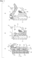
- FIGs. 1(a) and 1(b) illustrate a lever-type connector 10 described in Patent Literature 1 as a conventional example of a lever-type connector.
- FIG. 1(a) illustrates a state in which a lever 11 is on a separation position and
- FIG. 1(b) illustrates a state in which the lever 11 is on a fitted position.
- 12 denotes an outer housing and 13 denotes a front cover. Further, 14 denotes a slider and 15 denotes a wire cover.
- An inner housing, holding a contact, and the like (hidden and not seen) are accommodated in the outer housing 12 and the front cover 13 is attached to a front end of the inner housing.
- the lever 11 is attached to the outer housing 12 so as to rotate in both of an arrow a direction illustrated in FIG. 1 (a) and an arrow b direction illustrated in FIG. 1(b) with respect to the outer housing 12.
- FIG. 1(c) illustrates a state in the middle of fitting of the lever-type connector 10 with respect to a counterpart connector 20.
- a protrusion for slider movement 11a provided on the lever 11 is inserted and fitted to a concave portion 14d of the slider 14.
- the protrusion for slider movement 11a pushes the slider 14 in an arrow c direction in response to rotation of the lever 11 and the slider 14 slides in a slider accommodating groove 12a, which is provided to the outer housing 12, in conjunction with the lever 11.
- Cam grooves 14a to 14c are formed in the slider 14, as illustrated in FIG. 1(c) .
- cam pins 21a to 21c provided to a fitting portion 21 of the counterpart connector 20 are respectively inserted.
- the slider 14 is slid by rotating the lever 11 from the separation position illustrated in FIG. 1(a) to the fitted position illustrated in FIG. 1(b)
- the lever-type connector 10 and the counterpart connector 20 are mutually drawn by the action between the cam grooves 14a to 14c and the cam pins 21a to 21c, completing the fitting.
- a restricting protrusion 15a and a locking member 15b are provided to the wire cover 15 that is attached to a rear end of the outer housing 12.
- the restricting protrusion 15a restricts the rotation in the arrow a direction of the lever 11 from the separation position and the locking member 15b prevents the rotation in the arrow b direction of the lever 11 from the fitted position.
- Patent Literature 1 Japanese Patent Application Laid Open No. 2010-199025
- the lever 11 rotates if a greater force than the restricting force of the restricting protrusion 15a is applied to the lever 11. Therefore, if such a force is applied to the lever 11 even in other than the fitting with the counterpart connector 20, the lever 11 may rotate and the slider 14 may slide in conjunction with the lever 11.
- an object of the present invention is to provide a lever-type connector whose lever does not move even when a force is applied to the lever other than in fitting with a mating connector.
- a slider In a separation state between the lever-type connector and a mating connector, a slider is locked by a spring mechanism. Accordingly, a lever coupled to the slider does not move in the separation state. The locking by the spring mechanism is released at the start of fitting between the lever-type connector and the mating connector. A user can operate the lever coupled to the slider, in a non-separation state.
- the lever does not move from a predetermined position even when a force is applied to the lever in the separation state from the mating connector. Therefore, the present invention eliminates the necessity of the conventionally-required operation, which is checking whether a lever is on a predetermined position in fitting with a mating connector, and favorable usability is thus achieved.
- the lever-type connector 100 in this example is composed of an inner housing 30, an outer housing 40, two sliders 50U and 50L, a lever 60, a harness cover 70, a seal stopper 80, a seal ring 91, a retainer 92, a grommet, and a large number (75 in this example) of socket contacts.
- FIG. 3 illustrates the seal ring 91, the retainer 92, and the seal stopper 80 as these are attached to the inner housing 30 and FIG. 3 omits the illustration of the grommet and socket contacts.
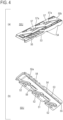
- FIGs. 4 and 5 illustrate details of the slider 50U and the inner housing 30 respectively. The shape of the slider 50U will be first described.
- the slider 50U has a substantially rectangular plate shape as illustrated in FIG. 4 , and one long side of a lower surface 50a is chamfered to be an inclined surface 51 formed along the long side.
- Each of the cam grooves 52 has an opening, which a driven boss of a later-described mating connector is to enter, on the long side on which the inclined surface 51 is formed.
- a projecting portion 53 projecting from the lower surface 50a is formed along the other long side of the lower surface 50a, and concave portions 54 are formed in a notched manner respectively on three spots in an extending direction of the projecting portion 53. Further, a groove 55 extending along the projecting portion 53 is formed on an inner side of the projecting portion 53 on the lower surface 50a.
- a rack 56 is formed on a side, which corresponds to the long side on which the projecting portion 53 is formed, in a manner to be positioned along a substantially half portion of the long side of the upper surface 50b.
- the teeth of the rack 56 are arrayed along the long side and the tips of the teeth are positioned on the long side.
- the rack 56 is formed by digging the upper surface 50b.
- two spring pieces 57 are formed on the upper surface 50b.
- the spring piece 57 cantilevers along the upper surface 50b and a convex portion 57a protruding from the upper surface 50b is formed on an end of the spring piece 57.
- two windows 58 are formed on the slider 50U in a manner to penetrate through the slider 50U in a thickness direction of the slider 50U.
- the two spring pieces 57 are integrally formed on the slider 50U so as to be positioned in these windows 58 respectively.
- the shape of the slider 50U has been described above.
- the other slider 50L has a shape mirroring the shape of the slider 50U and accordingly, portions corresponding to those of the slider 50U are provided with the same reference characters and detailed description thereof will be omitted.
- the inner housing 30 has a substantially rectangular parallelepiped outer shape as illustrated in FIG. 5 , and a large number of insertion holes 31 are formed inside in an array in a manner to penetrate in a front-rear direction. In the insertion holes 31, the socket contacts are inserted and held.
- a projection portion 32 which is long and thin is formed in a projecting manner. The projection portion 32 extends from one end to the other end of the upper surface 30a in a left-right direction which is orthogonal to the penetrating direction (the front-rear direction) of the insertion hole 31.
- a groove 33 is formed to extend along the projection portion 32.
- protrusions 34 are formed in a manner to be arrayed in an extending direction of the groove 33.
- the protrusion 34 protrudes in a triangular shape.
- a supporting shaft 35 is formed in a protruding manner on the rear end side from the groove 33 on the upper surface 30a. The supporting shaft 35 is used for attaching and supporting the lever 60.
- the projection portion 32, the groove 33, the protrusions 34, and the supporting shaft 35, which are described above, are also similarly formed on a lower surface 30b of the inner housing 30 so as to correspond to respective positions on the upper surface 30a.
- the outer housing 40 has a box shape having an accommodation space 41 as illustrated in FIG. 3 . Openings 44 each communicating with the accommodation space 41 are formed on upper portions and lower portions of left and right side surfaces 42 and 43 of the outer housing 40. Further, two small windows 47 are provided on each of an upper plate portion 45 and a bottom plate portion 46 of the outer housing 40.
- the lever 60 has a U shape formed by two arm portions 61 and a coupling portion 62 that couples the arm portions 61 to each other, as illustrated in FIG. 3 .
- a disc portion 63 is formed on one end (tip) of each arm portion 61, and a shaft hole 64 is formed on the center of the disc portion 63.
- a gear 65 centering on the shaft hole 64 is formed on an inner surface of each of the disc portions 63, which are opposed to each other, of the two arm portions 61.
- a protrusion 66 is formed on the coupling portion 62 that couples the other ends of the two arm portions 61.
- the lever-type connector 100 is assembled by accommodating the inner housing 30, to which the seal ring 91, the retainer 92, and the seal stopper 80 are attached as illustrated in FIG. 3 , in the accommodation space 41 of the outer housing 40 and by attaching the harness cover 70, the lever 60, and the sliders 50U and 50L. Wires of a wire harness which is not illustrated are threaded through grommets and connected to socket contacts whose illustration is omitted. The socket contacts are respectively inserted in the insertion holes 31 of the inner housing 30 and are held by the inner housing 30 and the retainer 92.
- the harness cover 70 is attached to the outer housing 40, and the lever 60 is attached to the inner housing 30 by threading a pair of supporting shafts 35 of the inner housing 30 through a pair of shaft holes 64 so that the lever 60 can rotate about the supporting shaft 35.
- the sliders 50U and 50L are inserted from the openings 44 on the side surface 42 side of the outer housing 40 and incorporated in the upper and lower spaces between the outer housing 40 and the inner housing 30, and the racks 56 of the sliders 50U and 50L are engaged with respective gears 65 of the lever 60.
- FIGs. 6(1) and 6(2) and FIGs. 7(3) and 7(4) illustrate processes (1) to (4) of fitting between the lever-type connector 100 and a mating connector 200 in order.
- FIGs. 6(1)(a) and 6(2)(a) and FIGs. 7(3)(a) and 7(4)(a) are plan views of the fitting state between the lever-type connector 100 and the mating connector 200.
- FIGs. 6(1)(b) and 6(2)(b) and FIGs. 7(3)(b) and 7(4)(b) illustrate an enlarged longitudinal section of a main portion of the fitting state.
- FIGs. 8(a) and 8(b) respectively illustrate a section taken along the E-E line shown in FIG. 6(1)(b) and a section taken along the F-F line shown in FIG. 6(2)(b) .
- FIG. 9 illustrates transverse sections on a position where the rack 56 of the slider 50U is positioned in the fitting state between the lever-type connector 100 and the mating connector 200.
- FIGs. 9(a), 9(b), and 9(d) correspond to the processes (2), (3), and (4) respectively and
- FIG. 9(c) corresponds to the state between the processes (3) and (4).
- the mating connector 200 has a configuration in which a large number of pin contacts 210 are arrayed and held in a housing 220 and the mating connector 200 is mounted on a substrate (not illustrated).
- a fitting portion 221 of the housing 220 of the mating connector 200 is inserted into a gap between the seal stopper 80, which is attached to the front end side of the inner housing 30, and the outer housing 40 in the lever-type connector 100.
- the end of the fitting portion 221 of the housing 220 in the mating connector 200 is abutted on the inclined surfaces 51 positioned on the front end in the fitting direction of the sliders 50U and 50L and the inclined surfaces 51 are pushed by the fitting portion 221. Accordingly, the sliders 50U and 50L are displaced in respective directions separating from the inner housing 30 against the spring force of the spring pieces 57. As a result, the protrusions 34 which have entered the concave portions 54 are disengaged from the concave portions 54 as illustrated in FIG. 8(b) and the locked state of the sliders 50U and 50L is thus released.
- the sliders 50U and 50L respectively ride up on upper and lower surfaces 221a and 221b of the fitting portion 221 of the housing 220 in the mating connector 200.
- three driven bosses 222 which are formed in a protruding manner on each of the upper surface 221a and the lower surface 221b of the fitting portion 221 of the housing 220 in the mating connector 200, enter corresponding cam grooves 52 of the sliders 50U and 50L as illustrated in FIG. 9(b) .
- the lever 60 becomes to be able to be operated in an arrow d direction around the supporting shaft 35.
- Separation between the mating connector 200 and the lever-type connector 100, that is, disengagement of the lever-type connector 100 from the mating connector 200 is performed by operating the lever 60 to return the lever 60 from the position illustrated in FIG. 7(4)(a) to the position illustrated in FIG. 6(1)(a) .
- lever-type connector 100 The configuration and operation of the lever-type connector according to the first embodiment of the present invention have been described above. According to the lever-type connector 100, the following actions and advantageous effects can be obtained.
- FIG. 10 illustrates an outer appearance of a lever-type connector 100z according to the second embodiment
- FIG. 11 illustrates the lever-type connector 100z as an exploded view with some portions removed.
- FIGs. 12(1) and 12(2) and FIGs. 13(3) and 13(4) illustrate processes (1) to (4) of fitting between the lever-type connector 100z and the mating connector 200 similarly to the processes (1) to (4) in the first embodiment.
- portions corresponding to those of the first embodiment will be provided with the same reference characters and detailed description thereof will be omitted.
- spring pieces which are provided for pushing sliders so as to produce a locked state of the sliders, are integrally formed not on the sliders but on an outer housing 40z.
- Two spring pieces 48 having a double-supported beam shape are formed on each of the upper plate portion 45 and the bottom plate portion 46 of the outer housing 40z.
- a convex portion 48a is formed in a protruding manner at the center in the longitudinal direction of an inner surface, facing the accommodation space 41, of each spring piece 48.
- recesses 59 are formed on the upper surface 50b of a slider 50Uz, and recesses 59 are also formed on a slider 50Lz in a similar manner.
- the sliders 50Uz and 50Lz are configured in a manner such that the sliders 50Uz and 50Lz are pushed by the convex portions 48a of the spring pieces 48, which are integrally formed on the outer housing 40z, to be in the locked state as is the case with the first embodiment.
- the operation in the processes (1) to (4) of fitting with the mating connector 200 is the same as that of the first embodiment other than that springs for pushing the sliders 50Uz and 50Lz against the inner housing 30 are the spring pieces 48 integrally formed on the outer housing 40z.
- the convex portions 48a of the spring pieces 48 enter and are positioned in respective recesses 59, which are provided to the sliders 50Uz and 50Lz. Accordingly, the spring pieces 48 are elastically restored and deformation thereof is relieved, and therefore, settling is prevented as is the case with the first embodiment.
- the spring pieces 57 are integrally formed on the sliders 50U and 50L in the first embodiment and the spring pieces 48 are integrally formed on the outer housing 40z in the second embodiment so as to push the sliders against the inner housing with the spring force of these spring pieces and to lock the sliders.
- a configuration in which such a spring piece is not intentionally provided can also be employed.
- a third embodiment employs such a configuration including no spring pieces, and the configuration and operation thereof will be described with reference to FIGs. 14 and 15 .
- the lever 60 of a lever-type connector has a U shape formed by two arm portions 61 and the coupling portion 62 that couples the arm portions 61 to each other as described above, as illustrated in FIG. 14 .
- these two arm portions 61 are configured to function as springs for pushing sliders 50Uzz and 50Lzz to produce the locked state of the sliders 50Uzz and 50Lzz.
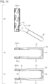
- FIG. 14 illustrates states of the lever 60 and the sliders 50Uzz and 50Lzz in the state of separation from a mating connector
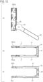
- FIG. 15 illustrates the states of the lever 60 and the sliders 50Uzz and 50Lzz when fitting to the mating connector is performed and the locked state of the sliders 50Uzz and 50Lzz is released.
- the sliders 50Uzz and 50Lzz are pressed in directions, in which the sliders 50Uzz and 50Lzz mutually approach, by the disc portion 63 and the gear 65, which are provided to each one end (tip) of two arm portions 61, as illustrated in FIG. 14 and thus, the sliders 50Uzz and 50Lzz can be locked.
- the sliders 50Uzz and 50Lzz are displaced in directions separating from each other against the spring force of two arm portions 61, as illustrated in FIG. 15 . In this state, the two arm portions 61 move opening in respective directions of arrows f.
- the lever 60 may be made function as a spring for pushing sliders.
- the protrusion for locking the slider and the concave portion which the protrusion enters may be provided to a slider and the concave portion may be provided to an inner housing in an opposite way to the embodiments.
Landscapes
- Details Of Connecting Devices For Male And Female Coupling (AREA)
- Coupling Device And Connection With Printed Circuit (AREA)
Abstract
Description
- The present invention relates to a lever-type connector that can reduce an operating force in fitting with and separation from a mating connector.
-
FIGs. 1(a) and 1(b) illustrate a lever-type connector 10 described inPatent Literature 1 as a conventional example of a lever-type connector.FIG. 1(a) illustrates a state in which alever 11 is on a separation position andFIG. 1(b) illustrates a state in which thelever 11 is on a fitted position. - In
FIGs. 1(a) and 1(b) , 12 denotes an outer housing and 13 denotes a front cover. Further, 14 denotes a slider and 15 denotes a wire cover. An inner housing, holding a contact, and the like (hidden and not seen) are accommodated in theouter housing 12 and thefront cover 13 is attached to a front end of the inner housing. - The
lever 11 is attached to theouter housing 12 so as to rotate in both of an arrow a direction illustrated inFIG. 1 (a) and an arrow b direction illustrated inFIG. 1(b) with respect to theouter housing 12. -
FIG. 1(c) illustrates a state in the middle of fitting of the lever-type connector 10 with respect to acounterpart connector 20. A protrusion forslider movement 11a provided on thelever 11 is inserted and fitted to aconcave portion 14d of theslider 14. The protrusion forslider movement 11a pushes theslider 14 in an arrow c direction in response to rotation of thelever 11 and theslider 14 slides in a slider accommodatinggroove 12a, which is provided to theouter housing 12, in conjunction with thelever 11. -
Cam grooves 14a to 14c are formed in theslider 14, as illustrated inFIG. 1(c) . Into thecam grooves 14a to 14c,cam pins 21a to 21c provided to a fittingportion 21 of thecounterpart connector 20 are respectively inserted. When theslider 14 is slid by rotating thelever 11 from the separation position illustrated inFIG. 1(a) to the fitted position illustrated inFIG. 1(b) , the lever-type connector 10 and thecounterpart connector 20 are mutually drawn by the action between thecam grooves 14a to 14c and thecam pins 21a to 21c, completing the fitting. - A restricting
protrusion 15a and alocking member 15b are provided to thewire cover 15 that is attached to a rear end of theouter housing 12. The restrictingprotrusion 15a restricts the rotation in the arrow a direction of thelever 11 from the separation position and thelocking member 15b prevents the rotation in the arrow b direction of thelever 11 from the fitted position. - Patent Literature 1:
Japanese Patent Application Laid Open No. 2010-199025 - In the lever-
type connector 10 described above, thelever 11 rotates if a greater force than the restricting force of the restrictingprotrusion 15a is applied to thelever 11. Therefore, if such a force is applied to thelever 11 even in other than the fitting with thecounterpart connector 20, thelever 11 may rotate and theslider 14 may slide in conjunction with thelever 11. - Such sliding of the
slider 14 causes deviation of the positions of thecam grooves 14a to 14c with respect to thecam pins 21a to 21c of thecounterpart connector 20, making the fitting with thecounterpart connector 20 impossible. This brings the necessity to check whether thelever 11 is on the separation position illustrated inFIG. 1(a) , that is, on a position on which rotation is restricted by the restrictingprotrusion 15a, in the fitting with thecounterpart connector 20. A case where the position is deviated requires an operation to raise thelever 11 and position thelever 11 on the position illustrated inFIG. 1(a) . Thus, the lever-type connector 10 of the related art illustrated inFIG. 1 requires such an operation, exhibiting poor usability. - In view of this situation, an object of the present invention is to provide a lever-type connector whose lever does not move even when a force is applied to the lever other than in fitting with a mating connector.
- The technical matters described herein are not intended to expressly or implicitly limit the invention described in the claims, or, moreover, are not a statement of the possibility of accepting such limitation by persons other than those who benefit from the present invention (for example, the applicant and the right holder), but are merely described to facilitate an understanding of the gist of the present invention. An overview of the present invention from another point of view can be understood, for example, from the scope of claims at the time of filing this patent application.
- In a separation state between the lever-type connector and a mating connector, a slider is locked by a spring mechanism. Accordingly, a lever coupled to the slider does not move in the separation state. The locking by the spring mechanism is released at the start of fitting between the lever-type connector and the mating connector. A user can operate the lever coupled to the slider, in a non-separation state.
- According to the present invention, the lever does not move from a predetermined position even when a force is applied to the lever in the separation state from the mating connector. Therefore, the present invention eliminates the necessity of the conventionally-required operation, which is checking whether a lever is on a predetermined position in fitting with a mating connector, and favorable usability is thus achieved.
-
-
FIG. 1 is a drawing illustrating a conventional lever-type connector.FIG. 1(a) is a plan view in a state in which a lever is on a separation position.FIG. 1(b) is a plan view in a state in which the lever is on a fitted position after rotating from the position illustrated inFIG. 1(a). FIG. 1(c) is a drawing for explaining a state in the middle of fitting between the lever-type connector illustrated inFIG. 1(a) and a counterpart connector. -
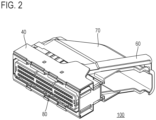
FIG. 2 is a perspective view illustrating a lever-type connector according to a first embodiment of the present invention. -
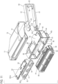
FIG. 3 is an exploded perspective view of the lever-type connector illustrated inFIG. 2 . -
FIG. 4 is a drawing illustrating one slider.FIG. 4(a) is an enlarged perspective view of one slider ofFIG. 3 viewed from above.FIG. 4(b) is an enlarged perspective view of one slider ofFIG. 3 viewed from below. -
FIG. 5 is a drawing illustrating an inner housing.FIG. 5(a) is an enlarged perspective view of the inner housing ofFIG. 3 viewed from above.FIG. 5(b) is an enlarged perspective view of the inner housing ofFIG. 3 viewed from below. -
FIG. 6 is a drawing for explaining processes of fitting between the lever-type connector illustrated inFIG. 2 and a mating connector.FIG. 6(1)(a) is a plan view of a fitting state between the lever-type connector and the mating connector in a process (1).FIG. 6(2)(a) is a plan view of a fitting state between the lever-type connector and the mating connector in a process (2).FIG. 6(1)(b) illustrates an enlarged longitudinal section of a main portion in the fitting state between the lever-type connector and the mating connector in the process (1).FIG. 6(2)(b) illustrates an enlarged longitudinal section of a main portion in the fitting state between the lever-type connector and the mating connector in the process (2). -
FIG. 7 is a drawing for explaining processes of fitting between the lever-type connector illustrated inFIG. 2 and the mating connector.FIG. 7(3)(a) is a plan view of a fitting state between the lever-type connector and the mating connector in a process (3).FIG. 7(4)(a) is a plan view of a fitting state between the lever-type connector and the mating connector in a process (4).FIG. 7(3)(b) illustrates an enlarged longitudinal section of a main portion in the fitting state between the lever-type connector and the mating connector in the process (3).FIG. 7(4)(b) illustrates an enlarged longitudinal section of a main portion in the fitting state between the lever-type connector and the mating connector in the process (4). -
FIG. 8 is a drawing for explaining processes of fitting between the lever-type connector illustrated inFIG. 2 and the mating connector.FIG. 8(a) is a sectional view taken along an E-E line shown inFIG. 6(1)(b) .FIG. 8(b) is a sectional view taken along an F-F line shown inFIG. 6(2)(b) . -
FIG. 9 illustrates transverse sections on a position where a rack of the slider is positioned in the fitting state between the lever-type connector illustrated inFIG. 2 and the mating connector.FIG. 9(a) is a transverse section in the process (2).FIG. 9(b) is a transverse section in the process (3).FIG. 9(c) is a transverse section in a state between the process (3) and the process (4).FIG. 9(d) is a transverse section in the process (4). -
FIG. 10 is a perspective view illustrating a lever-type connector according to a second embodiment of the present invention. -
FIG. 11 is an exploded perspective view of the lever-type connector illustrated inFIG. 10 . -
FIG. 12 is a drawing for explaining processes of fitting between the lever-type connector illustrated inFIG. 10 and a mating connector.FIG. 12(1)(a) is a plan view of a fitting state between the lever-type connector and the mating connector in a process (1).FIG. 12(2)(a) is a plan view of a fitting state between the lever-type connector and the mating connector in a process (2).FIG. 12(1)(b) illustrates an enlarged longitudinal section of a main portion in the fitting state between the lever-type connector and the mating connector in the process (1).FIG. 12(2)(b) illustrates an enlarged longitudinal section of a main portion in the fitting state between the lever-type connector and the mating connector in the process (2). -
FIG. 13 is a drawing for explaining processes of fitting between the lever-type connector illustrated inFIG. 10 and the mating connector.FIG. 13(3)(a) is a plan view of a fitting state between the lever-type connector and the mating connector in a process (3).FIG. 13(4)(a) is a plan view of a fitting state between the lever-type connector and the mating connector in a process (4).FIG. 13(3)(b) illustrates an enlarged longitudinal section of a main portion in the fitting state between the lever-type connector and the mating connector in the process (3).FIG. 13(4)(b) illustrates an enlarged longitudinal section of a main portion in the fitting state between the lever-type connector and the mating connector in the process (4). -
FIG. 14 is a drawing for explaining a lever-type connector according to a third embodiment of the present invention.FIG. 14(a) is a plan view illustrating states of a lever and a slider in a separation state between the lever-type connector and a mating connector.FIG. 14(b) is a side view ofFIG. 14(a). FIG. 14(c) is a partial sectional view ofFIG. 14(a) . -
FIG. 15 is a drawing for explaining the lever-type connector according to the third embodiment of the present invention.FIG. 15(a) is a plan view illustrating states of the lever and the slider when a locked state of the slider is released.FIG. 15(b) is a side view ofFIG. 15(a). FIG. 15(c) is a partial sectional view ofFIG. 15(a) . - Embodiments of the present invention will be described based on examples with reference to the accompanying drawings.
-
FIG. 2 illustrates an outer appearance of a lever-type connector according to a first embodiment of the present invention, andFIG. 3 illustrates the lever-type connector 100 shown inFIG. 2 as an exploded view with some portions removed. - The lever-
type connector 100 in this example is composed of aninner housing 30, anouter housing 40, twosliders lever 60, aharness cover 70, aseal stopper 80, aseal ring 91, aretainer 92, a grommet, and a large number (75 in this example) of socket contacts. Here,FIG. 3 illustrates theseal ring 91, theretainer 92, and theseal stopper 80 as these are attached to theinner housing 30 andFIG. 3 omits the illustration of the grommet and socket contacts. -
FIGs. 4 and5 illustrate details of theslider 50U and theinner housing 30 respectively. The shape of theslider 50U will be first described. - The
slider 50U has a substantially rectangular plate shape as illustrated inFIG. 4 , and one long side of alower surface 50a is chamfered to be aninclined surface 51 formed along the long side. On thelower surface 50a, threecam grooves 52 are further formed to be arrayed in a long side direction of theslider 50U. Each of thecam grooves 52 has an opening, which a driven boss of a later-described mating connector is to enter, on the long side on which theinclined surface 51 is formed. - A projecting
portion 53 projecting from thelower surface 50a is formed along the other long side of thelower surface 50a, andconcave portions 54 are formed in a notched manner respectively on three spots in an extending direction of the projectingportion 53. Further, agroove 55 extending along the projectingportion 53 is formed on an inner side of the projectingportion 53 on thelower surface 50a. - Meanwhile, on an
upper surface 50b of theslider 50U, arack 56 is formed on a side, which corresponds to the long side on which the projectingportion 53 is formed, in a manner to be positioned along a substantially half portion of the long side of theupper surface 50b. The teeth of therack 56 are arrayed along the long side and the tips of the teeth are positioned on the long side. Here, therack 56 is formed by digging theupper surface 50b. - Further, two
spring pieces 57 are formed on theupper surface 50b. Thespring piece 57 cantilevers along theupper surface 50b and aconvex portion 57a protruding from theupper surface 50b is formed on an end of thespring piece 57. Here, twowindows 58 are formed on theslider 50U in a manner to penetrate through theslider 50U in a thickness direction of theslider 50U. The twospring pieces 57 are integrally formed on theslider 50U so as to be positioned in thesewindows 58 respectively. - The shape of the
slider 50U has been described above. Theother slider 50L has a shape mirroring the shape of theslider 50U and accordingly, portions corresponding to those of theslider 50U are provided with the same reference characters and detailed description thereof will be omitted. - The
inner housing 30 has a substantially rectangular parallelepiped outer shape as illustrated inFIG. 5 , and a large number of insertion holes 31 are formed inside in an array in a manner to penetrate in a front-rear direction. In the insertion holes 31, the socket contacts are inserted and held. On anupper surface 30a of theinner housing 30, aprojection portion 32 which is long and thin is formed in a projecting manner. Theprojection portion 32 extends from one end to the other end of theupper surface 30a in a left-right direction which is orthogonal to the penetrating direction (the front-rear direction) of theinsertion hole 31. On a rear end side from theprojection portion 32 on theupper surface 30a, agroove 33 is formed to extend along theprojection portion 32. On a bottom surface of thegroove 33, fourprotrusions 34 are formed in a manner to be arrayed in an extending direction of thegroove 33. Theprotrusion 34 protrudes in a triangular shape. Here, a supportingshaft 35 is formed in a protruding manner on the rear end side from thegroove 33 on theupper surface 30a. The supportingshaft 35 is used for attaching and supporting thelever 60. - The
projection portion 32, thegroove 33, theprotrusions 34, and the supportingshaft 35, which are described above, are also similarly formed on alower surface 30b of theinner housing 30 so as to correspond to respective positions on theupper surface 30a. - The
outer housing 40 has a box shape having anaccommodation space 41 as illustrated inFIG. 3 .Openings 44 each communicating with theaccommodation space 41 are formed on upper portions and lower portions of left and right side surfaces 42 and 43 of theouter housing 40. Further, twosmall windows 47 are provided on each of anupper plate portion 45 and abottom plate portion 46 of theouter housing 40. - The
lever 60 has a U shape formed by twoarm portions 61 and acoupling portion 62 that couples thearm portions 61 to each other, as illustrated inFIG. 3 . Adisc portion 63 is formed on one end (tip) of eacharm portion 61, and ashaft hole 64 is formed on the center of thedisc portion 63. Agear 65 centering on theshaft hole 64 is formed on an inner surface of each of thedisc portions 63, which are opposed to each other, of the twoarm portions 61. Aprotrusion 66 is formed on thecoupling portion 62 that couples the other ends of the twoarm portions 61. - The configurations of the main portions have been described above. The lever-
type connector 100 is assembled by accommodating theinner housing 30, to which theseal ring 91, theretainer 92, and theseal stopper 80 are attached as illustrated inFIG. 3 , in theaccommodation space 41 of theouter housing 40 and by attaching theharness cover 70, thelever 60, and thesliders inner housing 30 and are held by theinner housing 30 and theretainer 92. - The
harness cover 70 is attached to theouter housing 40, and thelever 60 is attached to theinner housing 30 by threading a pair of supportingshafts 35 of theinner housing 30 through a pair of shaft holes 64 so that thelever 60 can rotate about the supportingshaft 35. Thesliders openings 44 on theside surface 42 side of theouter housing 40 and incorporated in the upper and lower spaces between theouter housing 40 and theinner housing 30, and theracks 56 of thesliders respective gears 65 of thelever 60. - A fitting operation between the lever-
type connector 100 described above and the mating connector will now be described with reference toFIGs. 6 to 9 . - FIGs. 6(1) and 6(2) and FIGs. 7(3) and 7(4) illustrate processes (1) to (4) of fitting between the lever-
type connector 100 and amating connector 200 in order.FIGs. 6(1)(a) and 6(2)(a) andFIGs. 7(3)(a) and 7(4)(a) are plan views of the fitting state between the lever-type connector 100 and themating connector 200.FIGs. 6(1)(b) and 6(2)(b) andFIGs. 7(3)(b) and 7(4)(b) illustrate an enlarged longitudinal section of a main portion of the fitting state.FIGs. 8(a) and 8(b) respectively illustrate a section taken along the E-E line shown inFIG. 6(1)(b) and a section taken along the F-F line shown inFIG. 6(2)(b) .FIG. 9 illustrates transverse sections on a position where therack 56 of theslider 50U is positioned in the fitting state between the lever-type connector 100 and themating connector 200.FIGs. 9(a), 9(b), and 9(d) correspond to the processes (2), (3), and (4) respectively andFIG. 9(c) corresponds to the state between the processes (3) and (4). - Fitting of the lever-
type connector 100 to themating connector 200 is started. Themating connector 200 has a configuration in which a large number ofpin contacts 210 are arrayed and held in ahousing 220 and themating connector 200 is mounted on a substrate (not illustrated). - With the start of fitting, a
fitting portion 221 of thehousing 220 of themating connector 200 is inserted into a gap between theseal stopper 80, which is attached to the front end side of theinner housing 30, and theouter housing 40 in the lever-type connector 100. - In this state, the
convex portions 57a of thespring pieces 57 of thesliders inner housing 30 and theouter housing 40 of the lever-type connector 100, are pushed by inner surfaces of theupper plate portion 45 and thebottom plate portion 46 of theouter housing 40. That is, thesliders spring pieces 57 to be maintained in a locked state in which theprotrusions 34 of theinner housing 30 enter theconcave portions 54, as illustrated inFIG. 8(a) . Here, the illustration of socket contacts and wire harnesses is omitted, but inFIG. 6(1)(b) , 93 denotes a grommet through which a wire of the wire harness is threaded. - As the fitting progresses, the end of the
fitting portion 221 of thehousing 220 in themating connector 200 is abutted on theinclined surfaces 51 positioned on the front end in the fitting direction of thesliders inclined surfaces 51 are pushed by thefitting portion 221. Accordingly, thesliders inner housing 30 against the spring force of thespring pieces 57. As a result, theprotrusions 34 which have entered theconcave portions 54 are disengaged from theconcave portions 54 as illustrated inFIG. 8(b) and the locked state of thesliders sliders lower surfaces fitting portion 221 of thehousing 220 in themating connector 200. - As the fitting further progresses, three driven
bosses 222, which are formed in a protruding manner on each of theupper surface 221a and thelower surface 221b of thefitting portion 221 of thehousing 220 in themating connector 200, enter correspondingcam grooves 52 of thesliders FIG. 9(b) . Thelever 60 becomes to be able to be operated in an arrow d direction around the supportingshaft 35. - In response to the operation of the
lever 60, thegears 65 which are rotating and theracks 56 mesh with each other and thesliders FIG. 9(c) . In response to the sliding operation of thesliders type connector 100 is drawn to themating connector 200 and thus, the fitting further progresses. - By rotating the
lever 60 to a position illustrated inFIG. 7(4)(a) , the fitting of the lever-type connector 100 to themating connector 200 is completed. The drivenbosses 222 of themating connector 200 are positioned on inner ends of thecam grooves 52 of thesliders FIG. 9(d) . - Separation between the
mating connector 200 and the lever-type connector 100, that is, disengagement of the lever-type connector 100 from themating connector 200 is performed by operating thelever 60 to return thelever 60 from the position illustrated inFIG. 7(4)(a) to the position illustrated inFIG. 6(1)(a) . - The configuration and operation of the lever-type connector according to the first embodiment of the present invention have been described above. According to the lever-
type connector 100, the following actions and advantageous effects can be obtained. - 1) In the state of separation from the
mating connector 200, as the state in the above-described process (1), thesliders spring pieces 57 to be in the locked state, in which theprotrusions 34 of theinner housing 30 enter theconcave portions 54, and the sliding operation thereof is thus blocked. Accordingly, thelever 60 which is coupled with thesliders
Even if a force operating thelever 60 is applied to thelever 60 in this state, the direction of the force is orthogonal to the direction of the spring force of thespring pieces 57 pushing thesliders sliders lever 60 does not move.
Thus, according to the lever-type connector 100, an operation for checking the position of thelever 60 is not required in fitting with themating connector 200. - 2) In the state of completion of fitting with the
mating connector 200, theconvex portions 57a of thespring pieces 57 enter and are positioned inrespective windows 47, which are provided to theouter housing 40 as illustrated inFIG. 7(4)(a) . Accordingly, thespring pieces 57 are elastically restored and deformation thereof is relieved, being able to prevent settling. - 3) The
sliders portion 53 provided along one long side is along the side surface of theprojection portion 32 provided to theinner housing 30. Therefore, thesliders projection portion 32 and perform favorable slide movement. - 4) In the state of completion of fitting with the
mating connector 200, theprotrusion 66 provided to thelever 60 is caught on aprojection portion 71 which is formed on theharness cover 70 in a projecting manner. Therefore, thelever 60 does not easily move and the position thereof is stably maintained. - 5) In the state of separation from the
mating connector 200, thelever 60 is locked as described above and the operation in the arrow d direction is blocked. Meanwhile, steppedportions 72 that protrude mutually outward are formed on theharness cover 70 as illustrated in FIG. - 3. Accordingly, even if a force in an opposite direction to the arrow d direction, for example, is applied to the
lever 60 in the state of separation from themating connector 200, the steppedportions 72 restrict movement of thelever 60. - A configuration of a lever-type connector according to a second embodiment of the present invention will now be described.
-
FIG. 10 illustrates an outer appearance of a lever-type connector 100z according to the second embodiment, andFIG. 11 illustrates the lever-type connector 100z as an exploded view with some portions removed. FIGs. 12(1) and 12(2) and FIGs. 13(3) and 13(4) illustrate processes (1) to (4) of fitting between the lever-type connector 100z and themating connector 200 similarly to the processes (1) to (4) in the first embodiment. InFIGs. 10 to 13 , portions corresponding to those of the first embodiment will be provided with the same reference characters and detailed description thereof will be omitted. - In this example, spring pieces, which are provided for pushing sliders so as to produce a locked state of the sliders, are integrally formed not on the sliders but on an
outer housing 40z. Twospring pieces 48 having a double-supported beam shape are formed on each of theupper plate portion 45 and thebottom plate portion 46 of theouter housing 40z. There are long andthin slits 49 on both sides in the width direction of eachspring piece 48, that is, thespring piece 48 is configured between theslits 49 which are provided in a pair. Aconvex portion 48a is formed in a protruding manner at the center in the longitudinal direction of an inner surface, facing theaccommodation space 41, of eachspring piece 48. - Meanwhile, recesses 59 are formed on the
upper surface 50b of a slider 50Uz, and recesses 59 are also formed on a slider 50Lz in a similar manner. - In this example, the sliders 50Uz and 50Lz are configured in a manner such that the sliders 50Uz and 50Lz are pushed by the
convex portions 48a of thespring pieces 48, which are integrally formed on theouter housing 40z, to be in the locked state as is the case with the first embodiment. The operation in the processes (1) to (4) of fitting with themating connector 200 is the same as that of the first embodiment other than that springs for pushing the sliders 50Uz and 50Lz against theinner housing 30 are thespring pieces 48 integrally formed on theouter housing 40z. - In the state of completion of fitting with the
mating connector 200, theconvex portions 48a of thespring pieces 48 enter and are positioned inrespective recesses 59, which are provided to the sliders 50Uz and 50Lz. Accordingly, thespring pieces 48 are elastically restored and deformation thereof is relieved, and therefore, settling is prevented as is the case with the first embodiment. - The
spring pieces 57 are integrally formed on thesliders spring pieces 48 are integrally formed on theouter housing 40z in the second embodiment so as to push the sliders against the inner housing with the spring force of these spring pieces and to lock the sliders. However, a configuration in which such a spring piece is not intentionally provided can also be employed. - A third embodiment employs such a configuration including no spring pieces, and the configuration and operation thereof will be described with reference to
FIGs. 14 and15 . - The
lever 60 of a lever-type connector has a U shape formed by twoarm portions 61 and thecoupling portion 62 that couples thearm portions 61 to each other as described above, as illustrated inFIG. 14 . In this example, these twoarm portions 61 are configured to function as springs for pushing sliders 50Uzz and 50Lzz to produce the locked state of the sliders 50Uzz and 50Lzz. -
FIG. 14 illustrates states of thelever 60 and the sliders 50Uzz and 50Lzz in the state of separation from a mating connector, andFIG. 15 illustrates the states of thelever 60 and the sliders 50Uzz and 50Lzz when fitting to the mating connector is performed and the locked state of the sliders 50Uzz and 50Lzz is released. - The sliders 50Uzz and 50Lzz are pressed in directions, in which the sliders 50Uzz and 50Lzz mutually approach, by the
disc portion 63 and thegear 65, which are provided to each one end (tip) of twoarm portions 61, as illustrated inFIG. 14 and thus, the sliders 50Uzz and 50Lzz can be locked. On the other hand, in the fitting state with the mating connector, the sliders 50Uzz and 50Lzz are displaced in directions separating from each other against the spring force of twoarm portions 61, as illustrated inFIG. 15 . In this state, the twoarm portions 61 move opening in respective directions of arrows f. - Thus, the
lever 60 may be made function as a spring for pushing sliders. - The embodiments of the lever-type connector according to the present invention have been described above. However, in terms of the protrusion for locking the slider and the concave portion which the protrusion enters, the protrusion may be provided to a slider and the concave portion may be provided to an inner housing in an opposite way to the embodiments.
-
- 10: lever-type connector
- 11: lever
- 11a: protrusion for slider movement
- 12: outer housing
- 12a: slider accommodating groove
- 13: front cover
- 14: slider
- 14a to 14c: cam groove
- 14d: concave portion
- 15: wire cover
- 15a: restricting protrusion
- 15b: locking member
- 20: counterpart connector
- 21: fitting portion
- 21a to 21c: cam pin
- 30: inner housing
- 30a: upper surface
- 30b: lower surface
- 31: insertion hole
- 32: projection portion
- 33: groove
- 34: protrusion
- 35: supporting shaft
- 40, 40z: outer housing
- 41: accommodation space
- 42, 43: side surface
- 44: opening
- 45: upper plate portion
- 46: bottom plate portion
- 47: window
- 48: spring piece
- 48a: convex portion
- 49: slit
- 50U, 50Uz, 50Uzz: slider
- 50L, 50Lz, 50Lzz: slider
- 50a: lower surface
- 50b: upper surface
- 51: inclined surface
- 52: cam groove
- 53: projecting portion
- 54: concave portion
- 55: groove
- 56: rack
- 57: spring piece
- 57a: convex portion
- 58: window
- 59: recess
- 60: lever
- 61: arm portion
- 62: coupling portion
- 63: disc portion
- 64: shaft hole
- 65: gear
- 66: protrusion
- 70: harness cover
- 71: projection portion
- 72: stepped portion
- 80: seal stopper
- 91: seal ring
- 92: retainer
- 93: grommet
- 100, 100z: lever-type connector
- 200: mating connector
- 210: pin contact
- 220: housing
- 221: fitting portion
- 221a: upper surface
- 221b: lower surface
- 222: driven boss
Claims (6)
- A lever-type connector comprising:a slider on which a cam groove, which a driven boss provided to a mating connector is to enter, is formed; anda lever that makes the slider perform a sliding operation, whereinfitting and separation between the lever-type connector and the mating connector are performed through an operation of the lever,the slider is positioned in a space between an inner housing, the inner housing holding a contact, and an outer housing accommodating the inner housing,the slider has an inclined surface on a front end in a fitting direction with the mating connector,a protrusion is formed on one of opposed surfaces of the slider and the inner housing and a concave portion is formed on the other,in a separation state from the mating connector, the slider is pushed by a spring to be in a locked state, in which the protrusion enters the concave portion, and accordingly, the sliding operation is blocked and the operation of the lever is blocked, andwhen fitting with the mating connector is started, the inclined surface of the slider is pushed by a housing of the mating connector, and accordingly, the slider is displaced in a direction separating from the inner housing against a spring force of the spring, and the locked state is released.
- The lever-type connector according to Claim 1, whereinthe spring is a spring piece that is integrally formed on the slider and has a convex portion, the convex portion being pushed by an inner surface of the outer housing, anda window, which the convex portion enters to elastically restore the spring piece in a state of completion of the fitting with the mating connector, is formed on the outer housing.
- The lever-type connector according to Claim 1, whereinthe spring is a spring piece that is integrally formed on the outer housing and has a convex portion, the convex portion pushing the slider, anda recess, which the convex portion enters to elastically restore the spring piece in a state of completion of the fitting with the mating connector, is formed on the slider.
- The lever-type connector according to any one of Claims 1 to 3, wherein the slider is positioned in each of upper and lower spaces between the inner housing and the outer housing.
- The lever-type connector according to Claim 1, whereinthe slider is positioned in each of upper and lower spaces between the inner housing and the outer housing,the lever has a U shape formed by two arm portions, whose one ends are positioned respectively on the two sliders, and a coupling portion that couples the other ends of the two arm portions to each other, andeach of the two arm portions functions as the spring.
- The lever-type connector according to any one of Claims 1 to 5, wherein the sliding operation of the slider, to which a rack is formed, is performed by rotating a gear through the operation of the lever, the gear being formed on the lever to be engaged with the rack.
Applications Claiming Priority (2)
| Application Number | Priority Date | Filing Date | Title |
|---|---|---|---|
| JP2020155553A JP7462523B2 (en) | 2020-09-16 | 2020-09-16 | Lever Type Connector |
| PCT/JP2021/022302 WO2022059276A1 (en) | 2020-09-16 | 2021-06-11 | Lever-type connector |
Publications (3)
| Publication Number | Publication Date |
|---|---|
| EP4216376A1 true EP4216376A1 (en) | 2023-07-26 |
| EP4216376A4 EP4216376A4 (en) | 2024-03-13 |
| EP4216376B1 EP4216376B1 (en) | 2025-08-20 |
Family
ID=80776790
Family Applications (1)
| Application Number | Title | Priority Date | Filing Date |
|---|---|---|---|
| EP21868963.6A Active EP4216376B1 (en) | 2020-09-16 | 2021-06-11 | Lever-type connector |
Country Status (6)
| Country | Link |
|---|---|
| US (1) | US20230307871A1 (en) |
| EP (1) | EP4216376B1 (en) |
| JP (1) | JP7462523B2 (en) |
| CN (1) | CN116250153A (en) |
| TW (1) | TWI802915B (en) |
| WO (1) | WO2022059276A1 (en) |
Families Citing this family (1)
| Publication number | Priority date | Publication date | Assignee | Title |
|---|---|---|---|---|
| JP7509822B2 (en) * | 2022-05-12 | 2024-07-02 | 矢崎総業株式会社 | Connector housings, connectors, and wire harnesses |
Family Cites Families (21)
| Publication number | Priority date | Publication date | Assignee | Title |
|---|---|---|---|---|
| EP0655799B1 (en) * | 1993-11-26 | 1999-10-06 | Molex Incorporated | Hooded electrical connector with terminal position assurance means |
| GB2334632B (en) * | 1998-02-23 | 2002-03-13 | Delphi Automotive Systems Gmbh | Two-part electrical connector |
| DE19844693A1 (en) * | 1998-09-29 | 2000-03-30 | Delphi Automotive Systems Gmbh | Two part electrical connector |
| ITTO20010290A1 (en) * | 2001-03-27 | 2002-09-27 | Framatome Connectors Italia | ELECTRIC CONNECTOR. |
| DE10360249A1 (en) * | 2003-12-20 | 2005-07-21 | Robert Bosch Gmbh | Power tool |
| JP2006331991A (en) * | 2005-05-30 | 2006-12-07 | Tyco Electronics Amp Kk | Lever-type connector |
| JP4523987B1 (en) | 2009-02-27 | 2010-08-11 | タイコエレクトロニクスジャパン合同会社 | Connector with slide cam |
| US7695296B1 (en) * | 2009-04-21 | 2010-04-13 | Tyco Electronics Corporation | Electrical connector with lever and camming slide |
| US8197270B2 (en) * | 2009-06-23 | 2012-06-12 | Tyco Electronics Corporation | Electrical connector having reversible wire dress |
| JP5500680B2 (en) * | 2010-03-26 | 2014-05-21 | タイコエレクトロニクスジャパン合同会社 | Lever type electrical connector |
| WO2013176139A1 (en) * | 2012-05-21 | 2013-11-28 | 住電朝日精工株式会社 | Connector |
| JP5846105B2 (en) * | 2012-11-13 | 2016-01-20 | 住友電装株式会社 | Lever type connector |
| US9160109B2 (en) * | 2013-12-13 | 2015-10-13 | Yazaki North America, Inc. | Lever actuated electrical center assembly |
| JP6482488B2 (en) * | 2016-03-04 | 2019-03-13 | 矢崎総業株式会社 | Lever type connector |
| JP6619285B2 (en) * | 2016-04-08 | 2019-12-11 | 日本航空電子工業株式会社 | Connector assembly |
| JP2017228442A (en) * | 2016-06-23 | 2017-12-28 | 日本圧着端子製造株式会社 | connector |
| JP6874015B2 (en) * | 2016-09-29 | 2021-05-19 | タイコエレクトロニクスジャパン合同会社 | Connector assembly |
| EP3392979B1 (en) * | 2017-04-19 | 2020-01-29 | Aptiv Technologies Limited | Electrical connector with lever and methods of assembling thereof |
| JP7081475B2 (en) * | 2018-12-21 | 2022-06-07 | 住友電装株式会社 | connector |
| KR102727971B1 (en) * | 2019-09-18 | 2024-11-07 | 현대자동차주식회사 | Connector assembly with a connector position assurance member |
| CN111193122A (en) * | 2020-02-26 | 2020-05-22 | 苏州远野汽车技术有限公司 | A rotary snap-fit connector |
-
2020
- 2020-09-16 JP JP2020155553A patent/JP7462523B2/en active Active
-
2021
- 2021-06-11 CN CN202180056231.2A patent/CN116250153A/en active Pending
- 2021-06-11 WO PCT/JP2021/022302 patent/WO2022059276A1/en not_active Ceased
- 2021-06-11 US US18/020,836 patent/US20230307871A1/en not_active Abandoned
- 2021-06-11 EP EP21868963.6A patent/EP4216376B1/en active Active
- 2021-06-18 TW TW110122383A patent/TWI802915B/en active
Also Published As
| Publication number | Publication date |
|---|---|
| JP2022049374A (en) | 2022-03-29 |
| WO2022059276A1 (en) | 2022-03-24 |
| EP4216376B1 (en) | 2025-08-20 |
| JP7462523B2 (en) | 2024-04-05 |
| EP4216376A4 (en) | 2024-03-13 |
| TWI802915B (en) | 2023-05-21 |
| US20230307871A1 (en) | 2023-09-28 |
| CN116250153A (en) | 2023-06-09 |
| TW202213880A (en) | 2022-04-01 |
Similar Documents
| Publication | Publication Date | Title |
|---|---|---|
| EP2311151B1 (en) | Checkable plug-in connection and method for checking the connection state of a plug-in connection | |
| EP2276123B1 (en) | Lever type connector | |
| JP3987736B2 (en) | Lever type connector | |
| JP2746012B2 (en) | connector | |
| US6733313B2 (en) | Connector having an operable member and a connector assembly | |
| JPH0722116A (en) | Cam fitting type electrical connector and its latch slide | |
| CN112217047A (en) | Lever type connector | |
| JP2004071572A (en) | Plug connector | |
| JP2011181460A (en) | Connector assembling jig | |
| JP3457146B2 (en) | Connector locking structure | |
| EP4216376B1 (en) | Lever-type connector | |
| JP3341810B2 (en) | LIF connector | |
| JP2019067744A (en) | connector | |
| JP2007265785A (en) | Electrical connector | |
| US6863463B2 (en) | Lever-type connector and connector assembly | |
| WO2023021858A1 (en) | Connector | |
| JP4289258B2 (en) | Fast connection terminal device | |
| KR20020024805A (en) | Connector | |
| JP7372067B2 (en) | connector | |
| KR20220094835A (en) | Connector assembly | |
| US12308572B2 (en) | Electrical plug connection having a self-locking function | |
| JP2004164933A (en) | Lever type connector | |
| JP2008277036A (en) | L-type contact | |
| JP7854368B2 (en) | Integrated member and assembly equipped with integrated member | |
| JP2008277035A (en) | Connector device |
Legal Events
| Date | Code | Title | Description |
|---|---|---|---|
| STAA | Information on the status of an ep patent application or granted ep patent |
Free format text: STATUS: THE INTERNATIONAL PUBLICATION HAS BEEN MADE |
|
| PUAI | Public reference made under article 153(3) epc to a published international application that has entered the european phase |
Free format text: ORIGINAL CODE: 0009012 |
|
| STAA | Information on the status of an ep patent application or granted ep patent |
Free format text: STATUS: REQUEST FOR EXAMINATION WAS MADE |
|
| 17P | Request for examination filed |
Effective date: 20230331 |
|
| AK | Designated contracting states |
Kind code of ref document: A1 Designated state(s): AL AT BE BG CH CY CZ DE DK EE ES FI FR GB GR HR HU IE IS IT LI LT LU LV MC MK MT NL NO PL PT RO RS SE SI SK SM TR |
|
| DAV | Request for validation of the european patent (deleted) | ||
| DAX | Request for extension of the european patent (deleted) | ||
| A4 | Supplementary search report drawn up and despatched |
Effective date: 20240212 |
|
| RIC1 | Information provided on ipc code assigned before grant |
Ipc: H01R 13/629 20060101AFI20240206BHEP |
|
| STAA | Information on the status of an ep patent application or granted ep patent |
Free format text: STATUS: EXAMINATION IS IN PROGRESS |
|
| 17Q | First examination report despatched |
Effective date: 20240702 |
|
| RAP3 | Party data changed (applicant data changed or rights of an application transferred) |
Owner name: JAPAN AVIATION ELECTRONICS INDUSTRY, LIMITED |
|
| GRAP | Despatch of communication of intention to grant a patent |
Free format text: ORIGINAL CODE: EPIDOSNIGR1 |
|
| STAA | Information on the status of an ep patent application or granted ep patent |
Free format text: STATUS: GRANT OF PATENT IS INTENDED |
|
| INTG | Intention to grant announced |
Effective date: 20250318 |
|
| GRAS | Grant fee paid |
Free format text: ORIGINAL CODE: EPIDOSNIGR3 |
|
| GRAA | (expected) grant |
Free format text: ORIGINAL CODE: 0009210 |
|
| STAA | Information on the status of an ep patent application or granted ep patent |
Free format text: STATUS: THE PATENT HAS BEEN GRANTED |
|
| AK | Designated contracting states |
Kind code of ref document: B1 Designated state(s): AL AT BE BG CH CY CZ DE DK EE ES FI FR GB GR HR HU IE IS IT LI LT LU LV MC MK MT NL NO PL PT RO RS SE SI SK SM TR |
|
| REG | Reference to a national code |
Ref country code: GB Ref legal event code: FG4D |
|
| REG | Reference to a national code |
Ref country code: CH Ref legal event code: EP |
|
| REG | Reference to a national code |
Ref country code: IE Ref legal event code: FG4D |
|
| REG | Reference to a national code |
Ref country code: DE Ref legal event code: R096 Ref document number: 602021036867 Country of ref document: DE |
|
| REG | Reference to a national code |
Ref country code: NL Ref legal event code: MP Effective date: 20250820 |
|
| PG25 | Lapsed in a contracting state [announced via postgrant information from national office to epo] |
Ref country code: IS Free format text: LAPSE BECAUSE OF FAILURE TO SUBMIT A TRANSLATION OF THE DESCRIPTION OR TO PAY THE FEE WITHIN THE PRESCRIBED TIME-LIMIT Effective date: 20251220 |
|
| PG25 | Lapsed in a contracting state [announced via postgrant information from national office to epo] |
Ref country code: NO Free format text: LAPSE BECAUSE OF FAILURE TO SUBMIT A TRANSLATION OF THE DESCRIPTION OR TO PAY THE FEE WITHIN THE PRESCRIBED TIME-LIMIT Effective date: 20251120 |
|
| REG | Reference to a national code |
Ref country code: LT Ref legal event code: MG9D |
|
| PG25 | Lapsed in a contracting state [announced via postgrant information from national office to epo] |
Ref country code: PT Free format text: LAPSE BECAUSE OF FAILURE TO SUBMIT A TRANSLATION OF THE DESCRIPTION OR TO PAY THE FEE WITHIN THE PRESCRIBED TIME-LIMIT Effective date: 20251222 |
|
| PG25 | Lapsed in a contracting state [announced via postgrant information from national office to epo] |
Ref country code: FI Free format text: LAPSE BECAUSE OF FAILURE TO SUBMIT A TRANSLATION OF THE DESCRIPTION OR TO PAY THE FEE WITHIN THE PRESCRIBED TIME-LIMIT Effective date: 20250820 |
|
| PG25 | Lapsed in a contracting state [announced via postgrant information from national office to epo] |
Ref country code: HR Free format text: LAPSE BECAUSE OF FAILURE TO SUBMIT A TRANSLATION OF THE DESCRIPTION OR TO PAY THE FEE WITHIN THE PRESCRIBED TIME-LIMIT Effective date: 20250820 Ref country code: NL Free format text: LAPSE BECAUSE OF FAILURE TO SUBMIT A TRANSLATION OF THE DESCRIPTION OR TO PAY THE FEE WITHIN THE PRESCRIBED TIME-LIMIT Effective date: 20250820 |
|
| PG25 | Lapsed in a contracting state [announced via postgrant information from national office to epo] |
Ref country code: GR Free format text: LAPSE BECAUSE OF FAILURE TO SUBMIT A TRANSLATION OF THE DESCRIPTION OR TO PAY THE FEE WITHIN THE PRESCRIBED TIME-LIMIT Effective date: 20251121 |
|
| PG25 | Lapsed in a contracting state [announced via postgrant information from national office to epo] |
Ref country code: SE Free format text: LAPSE BECAUSE OF FAILURE TO SUBMIT A TRANSLATION OF THE DESCRIPTION OR TO PAY THE FEE WITHIN THE PRESCRIBED TIME-LIMIT Effective date: 20250820 |
|
| PG25 | Lapsed in a contracting state [announced via postgrant information from national office to epo] |
Ref country code: LV Free format text: LAPSE BECAUSE OF FAILURE TO SUBMIT A TRANSLATION OF THE DESCRIPTION OR TO PAY THE FEE WITHIN THE PRESCRIBED TIME-LIMIT Effective date: 20250820 |
|
| PG25 | Lapsed in a contracting state [announced via postgrant information from national office to epo] |
Ref country code: BG Free format text: LAPSE BECAUSE OF FAILURE TO SUBMIT A TRANSLATION OF THE DESCRIPTION OR TO PAY THE FEE WITHIN THE PRESCRIBED TIME-LIMIT Effective date: 20250820 Ref country code: PL Free format text: LAPSE BECAUSE OF FAILURE TO SUBMIT A TRANSLATION OF THE DESCRIPTION OR TO PAY THE FEE WITHIN THE PRESCRIBED TIME-LIMIT Effective date: 20250820 |
|
| PG25 | Lapsed in a contracting state [announced via postgrant information from national office to epo] |
Ref country code: RS Free format text: LAPSE BECAUSE OF FAILURE TO SUBMIT A TRANSLATION OF THE DESCRIPTION OR TO PAY THE FEE WITHIN THE PRESCRIBED TIME-LIMIT Effective date: 20251120 |
|
| PG25 | Lapsed in a contracting state [announced via postgrant information from national office to epo] |
Ref country code: ES Free format text: LAPSE BECAUSE OF FAILURE TO SUBMIT A TRANSLATION OF THE DESCRIPTION OR TO PAY THE FEE WITHIN THE PRESCRIBED TIME-LIMIT Effective date: 20250820 |
|
| REG | Reference to a national code |
Ref country code: AT Ref legal event code: MK05 Ref document number: 1828391 Country of ref document: AT Kind code of ref document: T Effective date: 20250820 |
|
| PG25 | Lapsed in a contracting state [announced via postgrant information from national office to epo] |
Ref country code: SM Free format text: LAPSE BECAUSE OF FAILURE TO SUBMIT A TRANSLATION OF THE DESCRIPTION OR TO PAY THE FEE WITHIN THE PRESCRIBED TIME-LIMIT Effective date: 20250820 |
|
| PG25 | Lapsed in a contracting state [announced via postgrant information from national office to epo] |
Ref country code: DK Free format text: LAPSE BECAUSE OF FAILURE TO SUBMIT A TRANSLATION OF THE DESCRIPTION OR TO PAY THE FEE WITHIN THE PRESCRIBED TIME-LIMIT Effective date: 20250820 |
|
| PG25 | Lapsed in a contracting state [announced via postgrant information from national office to epo] |
Ref country code: AT Free format text: LAPSE BECAUSE OF FAILURE TO SUBMIT A TRANSLATION OF THE DESCRIPTION OR TO PAY THE FEE WITHIN THE PRESCRIBED TIME-LIMIT Effective date: 20250820 |
|
| PG25 | Lapsed in a contracting state [announced via postgrant information from national office to epo] |
Ref country code: IT Free format text: LAPSE BECAUSE OF FAILURE TO SUBMIT A TRANSLATION OF THE DESCRIPTION OR TO PAY THE FEE WITHIN THE PRESCRIBED TIME-LIMIT Effective date: 20250820 |
|
| PG25 | Lapsed in a contracting state [announced via postgrant information from national office to epo] |
Ref country code: CZ Free format text: LAPSE BECAUSE OF FAILURE TO SUBMIT A TRANSLATION OF THE DESCRIPTION OR TO PAY THE FEE WITHIN THE PRESCRIBED TIME-LIMIT Effective date: 20250820 |
|
| PG25 | Lapsed in a contracting state [announced via postgrant information from national office to epo] |
Ref country code: EE Free format text: LAPSE BECAUSE OF FAILURE TO SUBMIT A TRANSLATION OF THE DESCRIPTION OR TO PAY THE FEE WITHIN THE PRESCRIBED TIME-LIMIT Effective date: 20250820 Ref country code: SK Free format text: LAPSE BECAUSE OF FAILURE TO SUBMIT A TRANSLATION OF THE DESCRIPTION OR TO PAY THE FEE WITHIN THE PRESCRIBED TIME-LIMIT Effective date: 20250820 |
|
| REG | Reference to a national code |
Ref country code: DE Ref legal event code: R097 Ref document number: 602021036867 Country of ref document: DE |
|
| PLBE | No opposition filed within time limit |
Free format text: ORIGINAL CODE: 0009261 |
|
| STAA | Information on the status of an ep patent application or granted ep patent |
Free format text: STATUS: NO OPPOSITION FILED WITHIN TIME LIMIT |
|
| PG25 | Lapsed in a contracting state [announced via postgrant information from national office to epo] |
Ref country code: LT Free format text: LAPSE BECAUSE OF FAILURE TO SUBMIT A TRANSLATION OF THE DESCRIPTION OR TO PAY THE FEE WITHIN THE PRESCRIBED TIME-LIMIT Effective date: 20250820 |
|
| REG | Reference to a national code |
Ref country code: CH Ref legal event code: L10 Free format text: ST27 STATUS EVENT CODE: U-0-0-L10-L00 (AS PROVIDED BY THE NATIONAL OFFICE) Effective date: 20260701 |
|
| PGFP | Annual fee paid to national office [announced via postgrant information from national office to epo] |
Ref country code: GB Payment date: 20260505 Year of fee payment: 6 |
|
| PGFP | Annual fee paid to national office [announced via postgrant information from national office to epo] |
Ref country code: DE Payment date: 20260430 Year of fee payment: 6 |
|
| PGFP | Annual fee paid to national office [announced via postgrant information from national office to epo] |
Ref country code: FR Payment date: 20260511 Year of fee payment: 6 |
|
| 26N | No opposition filed |
Effective date: 20260521 |