EP4216353A1 - Battery, method and device for manufacturing same, and electrical device - Google Patents
Battery, method and device for manufacturing same, and electrical device Download PDFInfo
- Publication number
- EP4216353A1 EP4216353A1 EP21938132.4A EP21938132A EP4216353A1 EP 4216353 A1 EP4216353 A1 EP 4216353A1 EP 21938132 A EP21938132 A EP 21938132A EP 4216353 A1 EP4216353 A1 EP 4216353A1
- Authority
- EP
- European Patent Office
- Prior art keywords
- battery cell
- battery
- gap
- bonding member
- region
- Prior art date
- Legal status (The legal status is an assumption and is not a legal conclusion. Google has not performed a legal analysis and makes no representation as to the accuracy of the status listed.)
- Pending
Links
Images


Classifications
-
- H—ELECTRICITY
- H01—ELECTRIC ELEMENTS
- H01M—PROCESSES OR MEANS, e.g. BATTERIES, FOR THE DIRECT CONVERSION OF CHEMICAL ENERGY INTO ELECTRICAL ENERGY
- H01M50/00—Constructional details or processes of manufacture of the non-active parts of electrochemical cells other than fuel cells, e.g. hybrid cells
- H01M50/20—Mountings; Secondary casings or frames; Racks, modules or packs; Suspension devices; Shock absorbers; Transport or carrying devices; Holders
- H01M50/204—Racks, modules or packs for multiple batteries or multiple cells
-
- H—ELECTRICITY
- H01—ELECTRIC ELEMENTS
- H01M—PROCESSES OR MEANS, e.g. BATTERIES, FOR THE DIRECT CONVERSION OF CHEMICAL ENERGY INTO ELECTRICAL ENERGY
- H01M50/00—Constructional details or processes of manufacture of the non-active parts of electrochemical cells other than fuel cells, e.g. hybrid cells
- H01M50/20—Mountings; Secondary casings or frames; Racks, modules or packs; Suspension devices; Shock absorbers; Transport or carrying devices; Holders
- H01M50/233—Mountings; Secondary casings or frames; Racks, modules or packs; Suspension devices; Shock absorbers; Transport or carrying devices; Holders characterised by physical properties of casings or racks, e.g. dimensions
- H01M50/242—Mountings; Secondary casings or frames; Racks, modules or packs; Suspension devices; Shock absorbers; Transport or carrying devices; Holders characterised by physical properties of casings or racks, e.g. dimensions adapted for protecting batteries against vibrations, collision impact or swelling
-
- H—ELECTRICITY
- H01—ELECTRIC ELEMENTS
- H01M—PROCESSES OR MEANS, e.g. BATTERIES, FOR THE DIRECT CONVERSION OF CHEMICAL ENERGY INTO ELECTRICAL ENERGY
- H01M50/00—Constructional details or processes of manufacture of the non-active parts of electrochemical cells other than fuel cells, e.g. hybrid cells
- H01M50/30—Arrangements for facilitating escape of gases
-
- H—ELECTRICITY
- H01—ELECTRIC ELEMENTS
- H01M—PROCESSES OR MEANS, e.g. BATTERIES, FOR THE DIRECT CONVERSION OF CHEMICAL ENERGY INTO ELECTRICAL ENERGY
- H01M10/00—Secondary cells; Manufacture thereof
- H01M10/04—Construction or manufacture in general
-
- H—ELECTRICITY
- H01—ELECTRIC ELEMENTS
- H01M—PROCESSES OR MEANS, e.g. BATTERIES, FOR THE DIRECT CONVERSION OF CHEMICAL ENERGY INTO ELECTRICAL ENERGY
- H01M10/00—Secondary cells; Manufacture thereof
- H01M10/04—Construction or manufacture in general
- H01M10/0413—Large-sized flat cells or batteries for motive or stationary systems with plate-like electrodes
-
- H—ELECTRICITY
- H01—ELECTRIC ELEMENTS
- H01M—PROCESSES OR MEANS, e.g. BATTERIES, FOR THE DIRECT CONVERSION OF CHEMICAL ENERGY INTO ELECTRICAL ENERGY
- H01M10/00—Secondary cells; Manufacture thereof
- H01M10/04—Construction or manufacture in general
- H01M10/0431—Cells with wound or folded electrodes
-
- H—ELECTRICITY
- H01—ELECTRIC ELEMENTS
- H01M—PROCESSES OR MEANS, e.g. BATTERIES, FOR THE DIRECT CONVERSION OF CHEMICAL ENERGY INTO ELECTRICAL ENERGY
- H01M10/00—Secondary cells; Manufacture thereof
- H01M10/04—Construction or manufacture in general
- H01M10/0468—Compression means for stacks of electrodes and separators
-
- H—ELECTRICITY
- H01—ELECTRIC ELEMENTS
- H01M—PROCESSES OR MEANS, e.g. BATTERIES, FOR THE DIRECT CONVERSION OF CHEMICAL ENERGY INTO ELECTRICAL ENERGY
- H01M10/00—Secondary cells; Manufacture thereof
- H01M10/04—Construction or manufacture in general
- H01M10/0481—Compression means other than compression means for stacks of electrodes and separators
-
- H—ELECTRICITY
- H01—ELECTRIC ELEMENTS
- H01M—PROCESSES OR MEANS, e.g. BATTERIES, FOR THE DIRECT CONVERSION OF CHEMICAL ENERGY INTO ELECTRICAL ENERGY
- H01M10/00—Secondary cells; Manufacture thereof
- H01M10/05—Accumulators with non-aqueous electrolyte
- H01M10/058—Construction or manufacture
- H01M10/0587—Construction or manufacture of accumulators having only wound construction elements, i.e. wound positive electrodes, wound negative electrodes and wound separators
-
- H—ELECTRICITY
- H01—ELECTRIC ELEMENTS
- H01M—PROCESSES OR MEANS, e.g. BATTERIES, FOR THE DIRECT CONVERSION OF CHEMICAL ENERGY INTO ELECTRICAL ENERGY
- H01M50/00—Constructional details or processes of manufacture of the non-active parts of electrochemical cells other than fuel cells, e.g. hybrid cells
- H01M50/10—Primary casings; Jackets or wrappings
- H01M50/102—Primary casings; Jackets or wrappings characterised by their shape or physical structure
- H01M50/103—Primary casings; Jackets or wrappings characterised by their shape or physical structure prismatic or rectangular
-
- H—ELECTRICITY
- H01—ELECTRIC ELEMENTS
- H01M—PROCESSES OR MEANS, e.g. BATTERIES, FOR THE DIRECT CONVERSION OF CHEMICAL ENERGY INTO ELECTRICAL ENERGY
- H01M50/00—Constructional details or processes of manufacture of the non-active parts of electrochemical cells other than fuel cells, e.g. hybrid cells
- H01M50/10—Primary casings; Jackets or wrappings
- H01M50/102—Primary casings; Jackets or wrappings characterised by their shape or physical structure
- H01M50/105—Pouches or flexible bags
-
- H—ELECTRICITY
- H01—ELECTRIC ELEMENTS
- H01M—PROCESSES OR MEANS, e.g. BATTERIES, FOR THE DIRECT CONVERSION OF CHEMICAL ENERGY INTO ELECTRICAL ENERGY
- H01M50/00—Constructional details or processes of manufacture of the non-active parts of electrochemical cells other than fuel cells, e.g. hybrid cells
- H01M50/20—Mountings; Secondary casings or frames; Racks, modules or packs; Suspension devices; Shock absorbers; Transport or carrying devices; Holders
- H01M50/204—Racks, modules or packs for multiple batteries or multiple cells
- H01M50/207—Racks, modules or packs for multiple batteries or multiple cells characterised by their shape
- H01M50/209—Racks, modules or packs for multiple batteries or multiple cells characterised by their shape adapted for prismatic or rectangular cells
-
- H—ELECTRICITY
- H01—ELECTRIC ELEMENTS
- H01M—PROCESSES OR MEANS, e.g. BATTERIES, FOR THE DIRECT CONVERSION OF CHEMICAL ENERGY INTO ELECTRICAL ENERGY
- H01M50/00—Constructional details or processes of manufacture of the non-active parts of electrochemical cells other than fuel cells, e.g. hybrid cells
- H01M50/20—Mountings; Secondary casings or frames; Racks, modules or packs; Suspension devices; Shock absorbers; Transport or carrying devices; Holders
- H01M50/204—Racks, modules or packs for multiple batteries or multiple cells
- H01M50/207—Racks, modules or packs for multiple batteries or multiple cells characterised by their shape
- H01M50/213—Racks, modules or packs for multiple batteries or multiple cells characterised by their shape adapted for cells having curved cross-section, e.g. round or elliptic
-
- H—ELECTRICITY
- H01—ELECTRIC ELEMENTS
- H01M—PROCESSES OR MEANS, e.g. BATTERIES, FOR THE DIRECT CONVERSION OF CHEMICAL ENERGY INTO ELECTRICAL ENERGY
- H01M50/00—Constructional details or processes of manufacture of the non-active parts of electrochemical cells other than fuel cells, e.g. hybrid cells
- H01M50/20—Mountings; Secondary casings or frames; Racks, modules or packs; Suspension devices; Shock absorbers; Transport or carrying devices; Holders
- H01M50/262—Mountings; Secondary casings or frames; Racks, modules or packs; Suspension devices; Shock absorbers; Transport or carrying devices; Holders with fastening means, e.g. locks
-
- H—ELECTRICITY
- H01—ELECTRIC ELEMENTS
- H01M—PROCESSES OR MEANS, e.g. BATTERIES, FOR THE DIRECT CONVERSION OF CHEMICAL ENERGY INTO ELECTRICAL ENERGY
- H01M50/00—Constructional details or processes of manufacture of the non-active parts of electrochemical cells other than fuel cells, e.g. hybrid cells
- H01M50/20—Mountings; Secondary casings or frames; Racks, modules or packs; Suspension devices; Shock absorbers; Transport or carrying devices; Holders
- H01M50/262—Mountings; Secondary casings or frames; Racks, modules or packs; Suspension devices; Shock absorbers; Transport or carrying devices; Holders with fastening means, e.g. locks
- H01M50/264—Mountings; Secondary casings or frames; Racks, modules or packs; Suspension devices; Shock absorbers; Transport or carrying devices; Holders with fastening means, e.g. locks for cells or batteries, e.g. straps, tie rods or peripheral frames
-
- H—ELECTRICITY
- H01—ELECTRIC ELEMENTS
- H01M—PROCESSES OR MEANS, e.g. BATTERIES, FOR THE DIRECT CONVERSION OF CHEMICAL ENERGY INTO ELECTRICAL ENERGY
- H01M50/00—Constructional details or processes of manufacture of the non-active parts of electrochemical cells other than fuel cells, e.g. hybrid cells
- H01M50/20—Mountings; Secondary casings or frames; Racks, modules or packs; Suspension devices; Shock absorbers; Transport or carrying devices; Holders
- H01M50/289—Mountings; Secondary casings or frames; Racks, modules or packs; Suspension devices; Shock absorbers; Transport or carrying devices; Holders characterised by spacing elements or positioning means within frames, racks or packs
-
- H—ELECTRICITY
- H01—ELECTRIC ELEMENTS
- H01M—PROCESSES OR MEANS, e.g. BATTERIES, FOR THE DIRECT CONVERSION OF CHEMICAL ENERGY INTO ELECTRICAL ENERGY
- H01M50/00—Constructional details or processes of manufacture of the non-active parts of electrochemical cells other than fuel cells, e.g. hybrid cells
- H01M50/30—Arrangements for facilitating escape of gases
- H01M50/317—Re-sealable arrangements
- H01M50/325—Re-sealable arrangements comprising deformable valve members, e.g. elastic or flexible valve members
-
- H—ELECTRICITY
- H01—ELECTRIC ELEMENTS
- H01M—PROCESSES OR MEANS, e.g. BATTERIES, FOR THE DIRECT CONVERSION OF CHEMICAL ENERGY INTO ELECTRICAL ENERGY
- H01M50/00—Constructional details or processes of manufacture of the non-active parts of electrochemical cells other than fuel cells, e.g. hybrid cells
- H01M50/30—Arrangements for facilitating escape of gases
- H01M50/342—Non-re-sealable arrangements
- H01M50/3425—Non-re-sealable arrangements in the form of rupturable membranes or weakened parts, e.g. pierced with the aid of a sharp member
-
- H—ELECTRICITY
- H01—ELECTRIC ELEMENTS
- H01M—PROCESSES OR MEANS, e.g. BATTERIES, FOR THE DIRECT CONVERSION OF CHEMICAL ENERGY INTO ELECTRICAL ENERGY
- H01M50/00—Constructional details or processes of manufacture of the non-active parts of electrochemical cells other than fuel cells, e.g. hybrid cells
- H01M50/50—Current conducting connections for cells or batteries
- H01M50/572—Means for preventing undesired use or discharge
- H01M50/584—Means for preventing undesired use or discharge for preventing incorrect connections inside or outside the batteries
- H01M50/59—Means for preventing undesired use or discharge for preventing incorrect connections inside or outside the batteries characterised by the protection means
- H01M50/593—Spacers; Insulating plates
-
- H—ELECTRICITY
- H01—ELECTRIC ELEMENTS
- H01M—PROCESSES OR MEANS, e.g. BATTERIES, FOR THE DIRECT CONVERSION OF CHEMICAL ENERGY INTO ELECTRICAL ENERGY
- H01M2200/00—Safety devices for primary or secondary batteries
- H01M2200/20—Pressure-sensitive devices
-
- H—ELECTRICITY
- H01—ELECTRIC ELEMENTS
- H01M—PROCESSES OR MEANS, e.g. BATTERIES, FOR THE DIRECT CONVERSION OF CHEMICAL ENERGY INTO ELECTRICAL ENERGY
- H01M2220/00—Batteries for particular applications
- H01M2220/20—Batteries in motive systems, e.g. vehicle, ship, plane
-
- Y—GENERAL TAGGING OF NEW TECHNOLOGICAL DEVELOPMENTS; GENERAL TAGGING OF CROSS-SECTIONAL TECHNOLOGIES SPANNING OVER SEVERAL SECTIONS OF THE IPC; TECHNICAL SUBJECTS COVERED BY FORMER USPC CROSS-REFERENCE ART COLLECTIONS [XRACs] AND DIGESTS
- Y02—TECHNOLOGIES OR APPLICATIONS FOR MITIGATION OR ADAPTATION AGAINST CLIMATE CHANGE
- Y02E—REDUCTION OF GREENHOUSE GAS [GHG] EMISSIONS, RELATED TO ENERGY GENERATION, TRANSMISSION OR DISTRIBUTION
- Y02E60/00—Enabling technologies; Technologies with a potential or indirect contribution to GHG emissions mitigation
- Y02E60/10—Energy storage using batteries
-
- Y—GENERAL TAGGING OF NEW TECHNOLOGICAL DEVELOPMENTS; GENERAL TAGGING OF CROSS-SECTIONAL TECHNOLOGIES SPANNING OVER SEVERAL SECTIONS OF THE IPC; TECHNICAL SUBJECTS COVERED BY FORMER USPC CROSS-REFERENCE ART COLLECTIONS [XRACs] AND DIGESTS
- Y02—TECHNOLOGIES OR APPLICATIONS FOR MITIGATION OR ADAPTATION AGAINST CLIMATE CHANGE
- Y02P—CLIMATE CHANGE MITIGATION TECHNOLOGIES IN THE PRODUCTION OR PROCESSING OF GOODS
- Y02P70/00—Climate change mitigation technologies in the production process for final industrial or consumer products
- Y02P70/50—Manufacturing or production processes characterised by the final manufactured product
Definitions
- the present application relates to the technical field of batteries, and in particular relates to a battery and a method for manufacturing the battery, an apparatus of manufacturing the battery and an electricity-consuming device.
- the safety factor is also an issue that cannot be ignored. If the safety factor of the battery cell cannot be guaranteed, the battery cell cannot be used. Therefore, how to enhance the safety of battery cells has been an urgent technical problem to be solved in the battery technology.
- the present application provides a battery and a method for manufacturing the battery, an apparatus of manufacturing the battery and an electricity-consuming device, which can improve the service life and the safety of using the battery and the electricity-consuming device.
- the present application provides a battery, including a battery cell, a case assembly and a first bonding member.
- the case assembly is configured to accommodate the battery cell and includes a first portion, and the first portion is arranged at least at one side of the battery cell in a first direction. At least part of the first bonding member is filled between the first portion and the battery cell and bonds the first portion and the battery cell.
- a first gap is formed between the first portion and the battery cell, and the first gap is configured to release an expansion stress when the battery cell expands.
- the first bonding member is used to connect the battery cell and the case assembly, so that the battery has a higher overall rigidity and a higher structural strength.
- the first gap formed between the battery cell and the first portion reserves an expansion space for the battery cell, which can avoid the thermal runaway because an electrode assembly in the battery cell cannot expand, and improve the service life and safety of the battery.
- a space occupied by the first bonding member in the direction of the large surface of the battery cell can be reduced, and the energy density of the battery can be improved.
- the battery cell includes two first surfaces arranged to be opposite to each other in the first direction, the first bonding member is bonded to the first surface, and the first gap corresponds to a central region of the first surface.
- a direction of the expansion of the battery cell is perpendicular to the first surface
- a law of the expansion and deformation of the battery cell satisfies the characteristics of large middle and small edges
- the first gap corresponds to the central region of the first surface, so that there is an enough deformation space for the expansion of the battery cell to prevent potential safety hazards caused by the insufficient expansion of the battery cell.
- the first bonding member is arranged around the first gap.
- the first surface is a surface with the largest area of the battery cell.
- the first surface is the surface with the largest area of the battery cell.
- the first surface is arranged to directly face to the large surface of the electrode assembly inside the battery cell, so the first surface is a main deformation surface of the battery cell.
- At least one side of the first gap extends to an edge of the first surface.
- At least one side of the first gap extends to the edge of the first surface, so as to facilitate the exhaust of the first gap when it is compressed and avoid the "breathing" phenomenon, which may result in the failure of bonding of the first bonding member or the occurrence of air bubbles during bonding, from occurring in the first gap.
- the first surface includes a first region and a second region, the first bonding member is bonded to the first region, and the first gap is formed between the second region and the first portion.
- a ratio of an area of the second region to a total area of the first surface is 6%-45%.
- a dimension of the first surface in a second direction is L1, and a dimension of the second region in the second direction is X1, 1/4 ⁇ X1/L1 ⁇ 2/3; a dimension of the first surface in the third direction is L2, and a dimension of the second region in a third direction is X2, 1/4 ⁇ X2/L2 ⁇ 2/3; the second direction and the third direction are perpendicular to each other and both are parallel to the first surface.
- the strength of the battery and the deformation of the battery cell can be taken into account, and at the same time, it is convenient to apply glue and simplify the processing technology.
- the battery cell further includes two second surfaces arranged to be opposite to each other in a horizontal direction, in which the second surfaces are connected to the first surface, and a pressure relief mechanism arranged on the second surface; an opening of the first gap faces the pressure relief mechanism, and the pressure relief mechanism is configured to relieve an internal pressure of the battery cell when the internal pressure reaches to a threshold value.
- the first gap facing the pressure relief mechanism can prevent the first bonding member from spreading to the second surface and block the pressure relief mechanism, thereby ensuring the normal use of the pressure relief mechanism and improving safety.
- the battery further includes an isolation component, the isolation component is arranged between the first portion and the battery cell, and the isolation component surrounds the first gap and separates the first bonding member from the first gap.
- the isolation component effectively separates the first bonding member and the first gap, so as to prevent the first bonding member from spreading, reducing the first gap and affecting the expansion and deformation of the battery cell.
- the battery includes a plurality of battery cells, and the plurality of battery cells are arranged in at least two layers in the first direction.
- the battery further includes a second bonding member, and the second bonding member is filled between the adjacent battery cells.
- a second gap is formed between the adjacent battery cells, and the second gap is configured to release the expansion stress of the battery cells when the battery cells expand.
- the battery cells can release the expansion stress on the two first surfaces, so that the deformation of the battery cells can be uniform, and the service life of the battery can be improved.
- the case assembly includes a lower case body, an upper case cover and at least one fixing member, the fixing member is mounted on the lower case body, the lower case body and the upper case cover are arranged in the first direction and connected to each other, and the battery cell and the fixing member are arranged in an accommodating space surrounded by the lower case body and the upper case cover; one fixing member is provided, the battery cell is sandwiched and mounted between the fixing member and the lower case body, and a part of the lower case body or the fixing member arranged at the side of the battery cell in the first direction is the first portion; and/or two fixing portions are provided, the battery cell is sandwiched and mounted between the two fixing portions, and a part of the two fixing members arranged at the side of the battery cell in the first direction is the first portion.
- the battery cell includes the electrode assembly, and the electrode assembly includes a first electrode sheet and a second electrode sheet; the first electrode sheet and the second electrode sheet are wound around a winding axis and form a winding structure, and the winding axis is parallel to the first portion; or the electrode assembly includes a plurality of first electrode sheets and a plurality of second electrode sheets, and the plurality of first electrode sheets and the plurality of second electrode sheets are alternately stacked in the first direction; or the electrode assembly includes a plurality of second electrode sheets, the first electrode sheet includes a plurality of layer-stacking sections arranged to be stacked and a plurality of bending sections, each of the bending sections is connected to two adjacent layer-stacking sections, the plurality of layer-stacking sections and the plurality of second electrode sheets are alternately stacked in the first direction, and the first direction is perpendicular to the first portion.
- the embodiments of the present application provide an electricity-consuming device, including the battery according to any one of the above solutions, and the battery is configured to provide electrical energy.
- the embodiments of the present application provide a method for manufacturing the battery, including
- the embodiments of the present application provides an apparatus of manufacturing the battery, including
- the case assembly of the battery includes the first portion, the first bonding member is used to bond the battery cell and the first portion, and a first gap is arranged between the battery cell and the first portion, so that the first bonding member does not need to coat the entire surface of the battery cell, which can reduce the usage of the first bonding member and increase the energy density of the battery.
- the first gap reserves an expansion space for the battery cell, which can avoid the thermal runaway because the electrode assembly in the battery cell cannot expand, and improve the service life and safety of the battery.
- a space occupied by the first bonding member in the direction of the large surface of the battery cell can be reduced, and the energy density of the battery can be improved.
- the "embodiment” referred in the present application means that a particular feature, a structure, or a characteristic described in connection with the embodiment can be included in at least one embodiment of the present application.
- the appearances of the phrase in various positions in the specification are not necessarily all referring to the same embodiment, nor a separate or alternative embodiment that is mutually exclusive of other embodiments. It is explicitly and implicitly understood by those skilled in the art that the embodiments described in the present application may be combined with other embodiments.
- the terms “mount”, “communicate”, “connect” and “fix” should be understood in a broad sense, for example, it can be a fixed connection, a detachable connection, or an integral connection, it can be a mechanical connection or an electrical connection; it can be a direct connection, or it can be connected indirectly through an intermediary, it can be a communication within the two elements.
- the specific meaning of the above-mentioned terms in the present application can be understood according to specific situations.
- the term "and/or” is merely an association to describe the associated objects. It can mean that there are three kinds of relationships, such as A and/or B, which means that A exists alone, A and B exist at the same time, and B exists alone.
- the character "/" in the present application generally indicates that the related objects are an "or" relationship.
- the same reference numeral denotes the same component, and for the sake of brevity, the detailed description of the same component can be omitted in different embodiments. It should be understood that the thickness, length, width and other dimensions of various components in the embodiments of the present application shown in the accompanying drawings, as well as the overall thickness, length and width and the like of the integrated device are only exemplary descriptions, and should not constitute any limitation to the present application.
- the "plurality” refers to two or more (including two).
- the battery cell may include a lithium-ion secondary battery cell, a lithium-ion primary battery cell, a lithium-sulfur battery cell, a sodium-lithium-ion battery cell, a sodium-ion battery cell or a magnesium-ion battery cell and the like, which are not limited in the embodiments of the present application.
- the battery cell may be in a shape of a cylinder, a flat body, a cuboid or other shapes, which are not limited in the embodiments of the present application.
- the battery mentioned in the embodiments of the present application refers to a single physical module including one or more battery cells to provide a higher voltage and capacity.
- the battery mentioned in the present application may include a battery module or a battery pack or the like.
- the battery typically includes a case assembly for enclosing one or more battery cells.
- the case assembly can restrict the liquid or other foreign objects from affecting the charging or discharging of the battery cell.
- the battery cell includes an electrode assembly and an electrolyte, and the electrode assembly includes a positive electrode sheet, a negative electrode sheet and an isolation member.
- the battery cell mainly relies on the movement of metal ions between the positive electrode sheet and the negative electrode sheet to work.
- the positive electrode sheet includes a positive electrode current collector and a positive electrode active material layer, and the positive electrode active material layer coats a surface of the positive electrode current collector.
- the positive electrode current collector includes a positive electrode coating region and a positive electrode tab connected to the positive electrode coating region, the positive electrode coating region is coated with the positive electrode active material layer, and the positive electrode tab is not coated with the positive electrode active material layer.
- the material of the positive electrode current collector can be the aluminum, the positive electrode active material layer includes a positive electrode active material, and the positive electrode active material can be the lithium cobalt oxide, the lithium iron phosphate, the ternary lithium or the lithium manganate or the like.
- the negative electrode sheet includes a negative electrode current collector and a negative electrode active material layer, and the negative electrode active material layer coats a surface of the negative electrode current collector.
- the negative electrode current collector includes a negative electrode coating region and a negative electrode tab connected to the negative electrode coating region, the negative electrode coating region is coated with a negative electrode active material layer, and the negative electrode tab is not coated with the negative electrode active material layer.
- the material of the negative electrode current collector can be the copper, the negative electrode active material layer includes a negative electrode active material, and the negative electrode active material can be the carbon or the silicon or the like.
- the material of the isolation member may be PP (polypropylene, polypropylene) or PE (polyethylene, polyethylene).
- the battery cell of the battery is connected with the case assembly through a bonding member.
- the entire surface of the bonding member coats the surface of the battery cell, so as to connect the battery cell and the case assembly into a whole, and improve the overall rigidity and strength of the battery.
- the inventor found that, on the one hand, the solution of bonding the entire surface of the bonding member increases the usage of the bonding member and the weight of a battery system, which affects the energy density of the battery; on the other hand, the bonding member occupies an original reserved space in the direction of the large surface of the battery cell, which affects the expansion and the service life of the battery cell.
- the present application provides a technical solution.
- the case assembly includes a first portion, a first bonding member is used to bond the battery cell and the first portion, and a first gap is arranged between the battery cell and the first portion.
- the solution reduces the usage of the first bonding member, increases the energy density of the battery, and at the same time, the first gap can reserve an expansion space of the battery cell, thereby improving the safety and the service life of the battery.
- the electricity-consuming device can be a vehicle, a mobile phone, a portable device, a notebook computer, a ship, a spacecraft, an electric toy, an electric tool and the like.
- the vehicle can be a fuel vehicle, a gas vehicle or a new energy vehicle, and the new energy vehicle can be a pure electric vehicle, a hybrid vehicle or an extended-range vehicles or the like;
- the spacecraft includes an airplane, a rocket, a space shuttle and a spacecraft and the like;
- the electric toy includes a stationary or a mobile electric toy, such as a game console, an electric car toy, an electric ship toy, an electric airplane toys and the like;
- the power tool includes a metal cutting power tool, a grinding power tool, an assembling power tool, and a railway power tool, such as a power drill, a power grinder, a power wrench, a power screwdriver, a hammer, an impact drill, a concrete vibrator, a planers and the like.
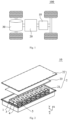
- Fig. 1 shows a schematic structural view of the vehicle provided by some embodiments of the present application.
- an interior of the vehicle 100 is provided with a battery 10.
- the battery 10 may be arranged at a bottom, a head or a rear of the vehicle 100.
- the battery 10 may be used for power supply of the vehicle 100, for example, the battery 10 may be used as an operating power source of the vehicle 100.
- the vehicle 100 may also include a controller 20 and a motor 30.
- the controller 20 can be used to control the battery 10 to supply power to the motor 30, for example, to meet the working power requirements of the vehicle 100 during starting, navigating and driving.
- the battery 10 can not only be used as the operating power source of the vehicle 100, but also can be used as a driving power source of the vehicle 100 to provide the driving power for the vehicle 100 instead of or partially instead of the fuel or the natural gas.
- Fig. 2 shows an exploded schematic view of the battery provided by some embodiments of the present application.
- the present application provides the battery 10, including a battery cell 1 and a case assembly 2.
- the battery cell 1 is configured to provide the electrical energy.
- the case assembly 2 is configured to accommodate the battery cell 1 and includes a first portion, and the first portion is arranged at least at one side of the battery cell 1 in a first direction.
- the battery 10 further includes a first bonding member 3. At least part of the first bonding member 3 is filled between the first portion and the battery cell 1 and bonds the first portion and the battery cell 1.
- a first gap 5 is formed between the first portion and the battery cell 1, and the first gap 5 is configured to release an expansion stress when the battery cell 1 expands.
- the first bonding member 3 is used to bond the battery cell 1 and the first portion, and the first gap 5 is arranged between the battery cell 1 and the first portion, so that the first bonding member 3 does not need to coat the entire surface of the battery cell 1, which can reduce the usage of the first bonding member 3 and increase the energy density of the battery 10.
- the first gap 5 reserves an expansion space for the battery cell 1, which can avoid the thermal runaway because the electrode assembly in the battery cell 1 cannot expand, and improve the service life and safety of the battery cell 1.
- a cartesian coordinate system X-Y-Z is defined.
- the first direction is defined as an X direction
- a second direction is defined as a Z direction
- a third direction is defined as a Y direction.
- the first direction X is a normal direction of the surface of the battery cell 1 for bonding the first bonding member 3.
- the case assembly 2 includes a lower case body 21, an upper case cover 22 and at least one fixing member 23, the fixing member 23 is mounted on the lower case body 21, the lower case body 21 and the upper case cover 22 are arranged in the first direction X and connected to each other, and the battery cell 1 and the fixing member 23 are arranged in an accommodating space surrounded by the lower case body 21 and the upper case cover 22; one fixing member 23 is provided, the battery cell 1 is sandwiched and mounted between the fixing member 23 and the lower case body 21, and a part of the lower case body 21 or the fixing member 23 arranged at the side of the battery cell 1 in the first direction X is the first portion; and/or two fixing portions are provided, the battery cell 1 is sandwiched and mounted between the two fixing portions 23, and a part of the two fixing members 23 arranged at the side of the battery cell 1 in the first direction X is the first portion.
- the case assembly 2 includes two fixing members 23. At least part of one fixing member 23 is arranged between the battery cell 1 and the lower case body 21, and at least part of the other fixing member 23 is arranged between the battery cell 1 and the upper case cover 22, and the first bonding member 3 is filled with between the battery cell 1 and the two fixing members 23.
- the portion of the two fixing members 23 arranged at one side of the battery cell 1 in the first direction X is the first portion.
- the case assembly 2 includes one fixing member 23. At least part of the fixing member 23 is arranged between the battery cell 1 and the upper case cover 22, a part of the first bonding member 3 is filled between the battery cell 1 and the fixing member 23, and a part of the first bonding member 3 is filled between the battery cell 1 and the lower case body 21.
- the case assembly 2 includes one fixing member 23. At least part of the fixing member 23 is arranged between the battery cell 1 and the lower case body 21, a part of the first bonding member 3 is filled between the battery cell 1 and the fixing member 23, and a part of the first bonding member 3 is filled between the battery cell 1 and the upper case cover 22.
- the case assembly 2 may also include only the lower case body 21 and the upper case cover 22, and the case assembly 2 does not include the fixing member 23.
- the battery cell 1 is directly bonded to the lower case body 21 and the upper case cover 22, a part of the first bonding member 3 is filled between the battery cell 1 and the lower case body 21, and a part of the first bonding member 3 is filled between the battery cell 1 and the upper case cover 22.
- the lower case body 21 and/or the upper case cover 22 is the first portion.
- the case assembly 2 can be of various structures.
- the lower case body 21 may be of a hollow structure with an opening at an end
- the upper case cover 22 may be of a plate-like structure
- the upper case cover 22 covers and closes at an opening side of the lower case body 21 to form the case assembly 2 with the accommodating space.
- Each of the lower case body 21 and the upper case cover 22 may also be a hollow structure with an opening at a side, and an opening side of the upper case cover 22 covers and closes the opening side of the lower case body 21 to form a case body with the accommodating space.
- the lower case body 21 and the upper case cover 22 may also be various shapes, such as a cylinder, a rectangular parallelepiped and the like.
- the fixing member 23 includes a first fixing portion bonded with the battery cell 1 and a second fixing portion fixed with the lower case body 21.
- the second fixing portion may be a structure bent toward the battery cell 1 relative to the first fixing portion, or the second fixing portion may be a separate component assembled to the first fixing portion.
- the second fixing portion is arranged at one side or two sides of the first fixing portion, and the second fixing portion and the lower case body 21 are connected by a screw or fixed by snapping.
- the lower case body 21 and the upper case cover 22 are connected together by means of the screw connection, the snapping connection or the glue connection.
- a sealing member such as a sealant, a sealing ring or the like, may also be arranged between the lower case body 21 and the upper case cover 22.
- the number of battery cells 1 may be one or more. If there are a plurality of battery cells 1, the plurality of battery cells 1 can be connected in series or in parallel or in a mixed connection, and the mixed connection means that the plurality of battery cells 1 have both the series connection and the parallel connection.
- the plurality of battery cells 1 can be connected in series, in parallel or mixed together, then the whole formed by the plurality of battery cells 1 is accommodated in the case, and the plurality of battery cells 1 are electrically connected through a bus component.
- the plurality of battery cells 1 can also be connected in series or in parallel or mixed to form a battery module, and then the plurality of battery modules can be connected in series or in parallel or mixed to form a whole and are accommodated in the case.
- Fig. 3 shows a structure view of some components of a battery provided by some embodiments of the present application
- Fig. 4 shows an exploded schematic view of some components of a battery provided by some embodiments of the present application.
- the battery cell 1 includes a shell 11, an electrode terminal 12 and a pressure relief mechanism 13, and each of the electrode terminal 12 and the pressure relief mechanism 13 is mounted on the shell 11.
- Two electrode terminals 12 are provided, the two electrode terminals 12 are used to lead the electric energy in the battery cell 1 to the outside, and the pressure relief mechanism 13 is used to release the pressure.
- the battery cell 1 further includes the electrode assembly, the electrode assembly is arranged in the shell 11, and the electrode assembly is used to supply the electrical energy.
- Fig. 5 shows a cross-sectional view of an electrode assembly of a battery provided by some embodiments of the present application. As shown in Fig. 5 , in some embodiments, the battery cell 1 includes the electrode assembly 14.
- the electrode assembly 14 includes a first electrode sheet 141 and a second electrode sheet 142.
- the first electrode sheet 141 and the second electrode sheet 142 are wound around a winding axis 144 to form a winding structure.
- the winding axis 144 is parallel to the first portion.
- Fig. 6 shows a cross-sectional view of an electrode assembly of a battery provided by some other embodiments of the present application.
- the electrode assembly 14 includes a plurality of first electrode sheets 141 and a plurality of second electrode sheets 142, and the plurality of first electrode sheets 141 and the plurality of second electrode sheets 142 are alternately stacked in the first direction X.
- Fig. 7 shows a cross-sectional view of an electrode assembly of a battery provided by some other embodiments of the present application, as shown in Fig. 7 , in some other embodiments, the electrode assembly 14 includes the first electrode 141 and the plurality of second electrode sheets 142, the first electrode sheet 141 includes a plurality of layer-stacking sections 1411 arranged to be stacked and a plurality of bending sections 1412, each of the bending sections 1412 is connected to two adjacent layer-stacking sections 1411, the plurality of layer-stacking sections 1411 and the plurality of second electrode sheets 142 are alternately stacked in the first direction X, and the first direction X is perpendicular to the first portion.
- the electrode assembly 14 further includes the isolation member 143 arranged between the first electrode sheet 141 and the second electrode sheet 142, and the isolation member 143 is used to form a channel for metal ions to pass through while preventing electrons from passing through.
- the polarities of the first electrode sheet 141 and the second electrode sheet 142 are not limited.
- the first electrode sheet 141 may be a positive electrode sheet
- the second electrode sheet 142 may be a negative electrode sheet
- the first electrode sheet 141 may be a negative electrode sheet
- the second electrode sheet 142 may be a positive electrode sheet.
- the two electrode terminals 12 are respectively electrically connected to a positive tab of the positive electrode sheet and a negative tab of the negative electrode sheet.
- the battery cell 1 includes two first surfaces 111 arranged to be opposite to each other in the first direction X, the first bonding member 3 is bonded to the first surface 111, and the first gap 5 corresponds to a central region of the first surface 111.
- a direction of the expansion of the battery cell 1 is perpendicular to the first surface 111, a law of the expansion and deformation of the battery cell 1 satisfies the characteristics of large middle and small edges, and the first gap 5 corresponds to the central region of the first surface 111, so that there is an enough deformation space for the expansion of the battery cell 1 to prevent potential safety hazards caused by the insufficient expansion of the battery cell 1.
- the shell 11 of the battery cell 1 is in the shape of a hexahedron, and the two first surfaces 111 are two surfaces of the shell 11 arranged to be opposite to each other in the first direction X.
- the first surface 111 is a surface with the largest area of the battery cell 1.
- the electrode assembly 14 includes two large faces.
- the two large faces are the two surfaces parallel to the first portion.
- the two large faces of the electrode assembly 14 directly face to the two first surfaces 111 of the battery cell 1 respectively.
- the electrode assembly 14 will expand in the normal direction of the large face during working, and the electrode assembly 14 expands and squeezes the shell 11 to cause the expansion of the first surface 111 of the battery cell 1.
- the first surface 111 is the surface with the largest area of the battery cell 1.
- the first surface 111 is arranged to directly face to the large surface of the electrode assembly 14 inside the battery cell 1, so the first surface 111 is a main deformation surface of the battery cell 1.
- the first bonding member 3 is arranged around the first gap 5.
- the first bonding member 3 may completely or partially surround the first gap 5.
- the first gap 5 is surrounded by the battery cell 1, the first portion and the first bonding member 3 to form a closed space.
- the first bonding member 3 partially surrounds the first gap 5 the first gap 5 is surrounded by the battery cell 1, the first portion and the first bonding member 3 to form a semi-closed space, and a portion of the first gap 5 that is not surrounded by the first bonding member 3 becomes an opening of the gap.
- At least one side of the first gap 5 extends to an edge of the first surface 111.
- the first gap 5 is the semi-closed space, and a side of the first gap 5 extending to the edge of the first surface 111 becomes the opening of the gap.
- the first surface 111 expands and deforms toward the first portion, a thickness of the first gap 5 in the first direction X decreases, and a volume of the first gap 5 decreases.
- the gas in the first gap 5 is compressed, and the compressed gas is discharged to a side face of the battery cell 1 from the opening of the gap.
- the first gap 5 By arranging the first gap 5 to be a semi-closed space, at least one side of the first gap 5 extending to the edge of the first surface 111 can discharge the compressed gas in time, thereby reducing the resistance of the compressed gas to the deformation of the battery cell 1, so as to prevent the battery cell 1 and the case assembly 2 from being poorly bonded due to the escape of compressed gas and improve the strength, the rigidity and the safety of the battery 10.
- the first surface 111 includes a first region 111a and a second region 111b, the first bonding member 3 is bonded to the first region 111a, and the first gap 5 is formed between the second region 111b and the first portion.
- the second region 111b is the region directly facing toward the first gap 5, so the second region 111b is the central region of the first surface 111, and the first region 111a is a peripheral region of the first surface 111 and communicates with the second region 111b. In some embodiments, at least one side of the second region 111b extends to the edge of the first surface 111, so that forms the opening of the gap can be formed by the second region 111b with the first portion and the first bonding member 3.
- a projected shape of the first gap 5 on the first surface 111 may be various shapes, such as a rectangle, a triangle, a circle or the like, as long as the first gap 5 directly faces to the central region of the first surface 111. That is, the shape of the second region 111b may be a rectangle, a triangle, a circle, or the like.
- a ratio of an area of the second region 111b to a total area of the first surface 111 is 6%-45%.
- the ratio of the area of the second region 111b to the total area of the first surface 111 is 10%-30%.
- the above area ratio of the second region 111b to the first surface 111 can not only make the first bonding member 3 have a sufficient bonding area, which can ensure the bonding firmness between the battery cell 1 and the case assembly 2, but also ensure the normal expansion and deformation of the battery cell 1, so that it can ensure the safety of the battery 10.
- the shape of the second region 111b is the rectangle.
- the shape of the second region 111b is arranged to be the rectangle, which can be convenient for being coated with the first bonding member 3 and improves the efficiency of coating.
- a dimension of the first surface 111 in the second direction Z is L1, and a dimension of the second region 111b in the second direction Z is X1, 1/4 ⁇ X1/L1 ⁇ 2/3; a dimension of the first surface 111 in the third direction Y is L2, and a dimension of the second region 111b in the third direction Y is X2, 1/4 ⁇ X2/L2 ⁇ 2/3; the second direction Z and the third direction Y are perpendicular to each other and both are parallel to the first surface 111.
- one side of the second region 111b coincides with one side of the first surface 111, and the side directly faces to the opening of the gap.
- the compressed gas is discharged from the opening of the gap toward the side face of the battery cell 1.
- two or three sides of the second region 111b can also overlap with the sides of the first surface 111 to better discharge the compressed gas.
- the battery cell 1 further includes two second surfaces 112 arranged to be opposite to each other in a horizontal direction.
- the second surface 112 is connected to the first surface 111.
- the battery cell 1 further includes the pressure relief mechanism 13.
- the pressure relief mechanism 13 is arranged on the second surface 112. An opening of the first gap 5 faces the pressure relief mechanism 13, and the pressure relief mechanism 13 is configured to relieve an internal pressure of the battery cell 1 when the internal pressure reaches to a threshold value.
- the two second surfaces 112 are two surfaces of the shell 11 of the battery cell 1 that are arranged to be opposite to each other in the third direction Y
- the battery cell 1 further includes two third surfaces 113.
- the two third surfaces 113 are two surfaces of the shell 11 arranged to be opposite to each other in the second direction Z, and the two third surfaces 113 are connected to the two second surfaces 112 and the two first surfaces 111.
- the second direction Z and the third direction Y are perpendicular to each other and are both parallel to the first surface 111.
- the pressure relief mechanism 13 communicates with an internal space of the battery cell 1.
- the pressure relief mechanism 13 can be opened toward the outside of the battery cell 1 to release the high-pressure gas when the internal pressure of the battery cell 1 reaches to or exceeds the threshold value.
- the pressure relief mechanism 13 generally forms a pressure relief valve.
- the first bonding member 3 After the first surface 111 of the battery cell 1 is coated with the first bonding member 3, the first bonding member 3 has the fluidity. The first bonding member 3 spreads to the periphery of the first surface 111, the second surface 112 and the third surface 113 as the assembly is pressurized. In this solution, the opening of the first gap 5 faces to the pressure relief mechanism 13, so that it can prevent the first bonding member 3 from spreading and blocking the pressure relief mechanism 13 to affect the exhaust of the battery cell 1, thereby improving the safety of the battery cell 1.
- the second surface 112 includes a third region 112a and a fourth region 112b that communicate with each other, the third region 112a is connected to the second region 111b, the fourth region 112b is connected to the first region 111a, and the pressure relief mechanism 13 is arranged in the third region 112a. Since the second region 111b directly faces to the first gap 5, the first bonding member 3 will not spread to the third region 112a during the assembly process of the battery 10, thereby ensuring the normal operation of the pressure relief mechanism 13.
- the pressure relief mechanism 13 can also be arranged on the third surface 113 of the battery cell 1, as long as it is ensured that the opening of the first gap 5 faces to the pressure relief mechanism 13.
- the first bonding member 3 has the bondable property, the first bonding member 3 is liquid or paste-like before solidification, has a certain fluidity, and become solid after solidification.
- the first bonding member 3 includes one or more of an epoxy resin, a polyurethane and an acrylic resin. The first bonding member 3 coats the first surface 111 of the battery cell 1 and/or the surface at the side of the first portion facing toward the battery cell 1.
- the battery 10 further includes an isolation component 4.
- the isolation component 4 is arranged between the first portion and the battery cell 1, and the isolation component 4 surrounds the first gap 5 and separates the first bonding member 3 from the first gap 5.
- the isolation component 4 can effectively prevent the first bonding member 3 from spreading toward the first gap 5, avoid the first bonding member 3 from spreading to cause the projected area of the first gap 5 to decrease, and ensure that the battery cell 1 has a sufficient space for expansion and deformation.
- the isolation component 4 corresponds to a region where the first bonding member 3 surrounds the first gap 5.
- the isolation component 4 completely surrounds the first gap 5, and the first gap 5 is a closed space; in other embodiments, the isolation component 4 partially surrounds the first gap 5, and a part of the isolation component 4 that does not surround the first gap 5 forms the opening of the first gap 5, and the opening is used to discharge the gas in the first gap 5 when the battery cell 1 expands.
- the isolation component 4 is made of a foam, a rubber and other breathable and compressible materials.
- a compressed thickness of the isolation component 4 is not less than a thickness of the first bonding member 3 to prevent the first bonding member 3 from spreading into the first gap 5. At the same time, it can ensure the bonding firmness between the battery cell 1 and the case assembly 2.
- the first bonding member 3 bonds the battery cell 1 and the first portion into a whole, and the isolation component 4 compresses and separates the first bonding member 3 and the first gap 5.
- the battery cell 1 is repeatedly charged and discharged, the battery cell 1 is expanded and deformed, and the first surface 111 of the battery cell 1 expands toward the first portion in the first direction X, so that the first gap 5 is compressed.
- the first gap 5 isolates the first surface 111 from the first portion, so that it can avoid the expansion and deformation of the first portion caused by the first surface 111 expanding and squeezing the first portion, thereby improving the service life and safety of the battery 10.
- the plurality of battery cells 1 of the battery 10 are arranged in at least two layers in the first direction X.
- the battery further includes a second bonding member 6, and the second bonding member 6 is filled between the adjacent battery cells.
- a second gap 7 is formed between the adjacent battery cells 1, and the second gap 7 is configured to release the expansion stress of the battery cells 1 when the battery cells 1 expand.
- the second bonding member 6 adopts a double-sided tape, and two bonding surfaces of the double-sided tape are respectively bonded to the first surfaces 111 of the two adjacent battery cells 1.
- the second bonding member 6 can also be made of the same material as the first bonding member 3, and the isolation member 4 can also be arranged between two adjacent battery cells 1 to isolate the second bonding member 6 from the second gap 7.
- the second gap 7 directly faces to the central region of the first surface 111, the shape and structure of the second gap 7 are not restricted, the shape of the second gap 7 can be the circle, the rectangle or the triangle, and the second gap 7 may be of a closed structure or may have an opening.
- the second gap 7 can release the expansion stress of the battery cells 1 along the two first surfaces 111, so that the battery cells 1 can be deformed uniformly, and the life and safety of the battery cells 1 can be improved.
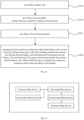
- Fig. 11 shows a flow chart of a method for manufacturing a battery provided by some embodiments of the present application. As shown in Fig. 11 , the flow chart of the method for manufacturing the battery provided by the embodiment of the present application includes:
- S300 arranging the first portion at least at one side of the battery cell 1 in a first direction X, filling at least part of the first bonding member 3 between the first portion and the battery cell 1 and bonds the first portion and the battery cell 1, and forming a first gap 5 is formed between the first portion and the battery cell 1, in which the first gap 5 is configured to release an expansion stress when the battery cell 1 expands.
- the battery 10 provided by the above-mentioned embodiments can be referred to.
- Fig. 12 is a schematic block view of an apparatus of manufacturing a battery provided by some embodiments of the present application. As shown in Fig. 12 , an apparatus of manufacturing the battery 10 includes
- the battery provided by the above-mentioned embodiments can be referred to.
Landscapes
- Chemical & Material Sciences (AREA)
- Chemical Kinetics & Catalysis (AREA)
- Electrochemistry (AREA)
- General Chemical & Material Sciences (AREA)
- Engineering & Computer Science (AREA)
- Manufacturing & Machinery (AREA)
- Battery Mounting, Suspending (AREA)
- Secondary Cells (AREA)
- Gas Exhaust Devices For Batteries (AREA)
Abstract
Description
- The present application relates to the technical field of batteries, and in particular relates to a battery and a method for manufacturing the battery, an apparatus of manufacturing the battery and an electricity-consuming device.
- Energy savings and emission reduction are the keys to the sustainable development of the automobile industry. An electric vehicle has become an important part of the sustainable development of the automobile industry due to the advantage of energy saving and environmental protection. For the electric vehicle, the battery technology is an important factor in its development.
- In the development of the battery technology, in addition to improving the performance of a battery cell, the safety factor is also an issue that cannot be ignored. If the safety factor of the battery cell cannot be guaranteed, the battery cell cannot be used. Therefore, how to enhance the safety of battery cells has been an urgent technical problem to be solved in the battery technology.
- The present application provides a battery and a method for manufacturing the battery, an apparatus of manufacturing the battery and an electricity-consuming device, which can improve the service life and the safety of using the battery and the electricity-consuming device.
- In a first aspect, the present application provides a battery, including a battery cell, a case assembly and a first bonding member. The case assembly is configured to accommodate the battery cell and includes a first portion, and the first portion is arranged at least at one side of the battery cell in a first direction. At least part of the first bonding member is filled between the first portion and the battery cell and bonds the first portion and the battery cell. A first gap is formed between the first portion and the battery cell, and the first gap is configured to release an expansion stress when the battery cell expands.
- In the technical solution of the present application, the first bonding member is used to connect the battery cell and the case assembly, so that the battery has a higher overall rigidity and a higher structural strength. The first gap formed between the battery cell and the first portion reserves an expansion space for the battery cell, which can avoid the thermal runaway because an electrode assembly in the battery cell cannot expand, and improve the service life and safety of the battery. At the same time, by forming the first gap, a space occupied by the first bonding member in the direction of the large surface of the battery cell can be reduced, and the energy density of the battery can be improved.
- In some embodiments, the battery cell includes two first surfaces arranged to be opposite to each other in the first direction, the first bonding member is bonded to the first surface, and the first gap corresponds to a central region of the first surface.
- In the above solution, a direction of the expansion of the battery cell is perpendicular to the first surface, a law of the expansion and deformation of the battery cell satisfies the characteristics of large middle and small edges, and the first gap corresponds to the central region of the first surface, so that there is an enough deformation space for the expansion of the battery cell to prevent potential safety hazards caused by the insufficient expansion of the battery cell.
- In some embodiments, the first bonding member is arranged around the first gap.
- In some embodiments, the first surface is a surface with the largest area of the battery cell.
- In the above solution, the first surface is the surface with the largest area of the battery cell. The first surface is arranged to directly face to the large surface of the electrode assembly inside the battery cell, so the first surface is a main deformation surface of the battery cell. By arranging the first gap corresponding to the first surface, the expansion of the battery cell can be better absorbed, and the service life and the safety of the battery can be improved.
- In some embodiments, at least one side of the first gap extends to an edge of the first surface.
- In the above solution, at least one side of the first gap extends to the edge of the first surface, so as to facilitate the exhaust of the first gap when it is compressed and avoid the "breathing" phenomenon, which may result in the failure of bonding of the first bonding member or the occurrence of air bubbles during bonding, from occurring in the first gap.
- In some embodiments, the first surface includes a first region and a second region, the first bonding member is bonded to the first region, and the first gap is formed between the second region and the first portion.
- In some embodiments, a ratio of an area of the second region to a total area of the first surface is 6%-45%.
- In some embodiments, a dimension of the first surface in a second direction is L1, and a dimension of the second region in the second direction is X1, 1/4≤X1/L1≤2/3; a dimension of the first surface in the third direction is L2, and a dimension of the second region in a third direction is X2, 1/4≤X2/L2≤2/3; the second direction and the third direction are perpendicular to each other and both are parallel to the first surface.
- In the above solution, by defining the shape and area of the second region, the strength of the battery and the deformation of the battery cell can be taken into account, and at the same time, it is convenient to apply glue and simplify the processing technology.
- In some embodiments, the battery cell further includes two second surfaces arranged to be opposite to each other in a horizontal direction, in which the second surfaces are connected to the first surface, and a pressure relief mechanism arranged on the second surface; an opening of the first gap faces the pressure relief mechanism, and the pressure relief mechanism is configured to relieve an internal pressure of the battery cell when the internal pressure reaches to a threshold value.
- In the above solution, the first gap facing the pressure relief mechanism can prevent the first bonding member from spreading to the second surface and block the pressure relief mechanism, thereby ensuring the normal use of the pressure relief mechanism and improving safety.
- In some embodiments, the battery further includes an isolation component, the isolation component is arranged between the first portion and the battery cell, and the isolation component surrounds the first gap and separates the first bonding member from the first gap. The isolation component effectively separates the first bonding member and the first gap, so as to prevent the first bonding member from spreading, reducing the first gap and affecting the expansion and deformation of the battery cell.
- In some embodiments, the battery includes a plurality of battery cells, and the plurality of battery cells are arranged in at least two layers in the first direction. The battery further includes a second bonding member, and the second bonding member is filled between the adjacent battery cells. A second gap is formed between the adjacent battery cells, and the second gap is configured to release the expansion stress of the battery cells when the battery cells expand.
- In the above solution, by arranging the second gap, the battery cells can release the expansion stress on the two first surfaces, so that the deformation of the battery cells can be uniform, and the service life of the battery can be improved.
- In some embodiments, the case assembly includes a lower case body, an upper case cover and at least one fixing member, the fixing member is mounted on the lower case body, the lower case body and the upper case cover are arranged in the first direction and connected to each other, and the battery cell and the fixing member are arranged in an accommodating space surrounded by the lower case body and the upper case cover; one fixing member is provided, the battery cell is sandwiched and mounted between the fixing member and the lower case body, and a part of the lower case body or the fixing member arranged at the side of the battery cell in the first direction is the first portion; and/or two fixing portions are provided, the battery cell is sandwiched and mounted between the two fixing portions, and a part of the two fixing members arranged at the side of the battery cell in the first direction is the first portion.
- In some embodiments, the battery cell includes the electrode assembly, and the electrode assembly includes a first electrode sheet and a second electrode sheet; the first electrode sheet and the second electrode sheet are wound around a winding axis and form a winding structure, and the winding axis is parallel to the first portion; or the electrode assembly includes a plurality of first electrode sheets and a plurality of second electrode sheets, and the plurality of first electrode sheets and the plurality of second electrode sheets are alternately stacked in the first direction; or the electrode assembly includes a plurality of second electrode sheets, the first electrode sheet includes a plurality of layer-stacking sections arranged to be stacked and a plurality of bending sections, each of the bending sections is connected to two adjacent layer-stacking sections, the plurality of layer-stacking sections and the plurality of second electrode sheets are alternately stacked in the first direction, and the first direction is perpendicular to the first portion.
- In a second aspect, the embodiments of the present application provide an electricity-consuming device, including the battery according to any one of the above solutions, and the battery is configured to provide electrical energy.
- In a third aspect, the embodiments of the present application provide a method for manufacturing the battery, including
- providing a battery cell;
- providing a case assembly, in which the case assembly includes a first portion;
- providing a first bonding member;
- arranging the first portion at least at one side of the battery cell in a first direction, filling at least part of the first bonding member between the first portion and the battery cell and bonds the first portion and the battery cell, and forming a first gap is formed between the first portion and the battery cell, in which the first gap is configured to release an expansion stress when the battery cell expands.
- In a fourth aspect, the embodiments of the present application provides an apparatus of manufacturing the battery, including
- a first providing device, configured to provide a battery cell;
- a second providing device, configured to provide a case assembly, in which the case assembly includes a first portion;
- a first assembling device, configured to arrange the first portion at least at one side of the battery cell in a first direction;
- a third providing device, configured to provide a first bonding member;
- a second assembling device, configured to fill at least part of the first bonding member between the first portion and the battery cell and bonds the first portion and the battery cell, in which a first gap is formed between the first portion and the battery cell, and the first gap is configured to release an expansion stress when the battery cell expands.
- According to the solutions provided by the embodiments of the present application, the case assembly of the battery includes the first portion, the first bonding member is used to bond the battery cell and the first portion, and a first gap is arranged between the battery cell and the first portion, so that the first bonding member does not need to coat the entire surface of the battery cell, which can reduce the usage of the first bonding member and increase the energy density of the battery. The first gap reserves an expansion space for the battery cell, which can avoid the thermal runaway because the electrode assembly in the battery cell cannot expand, and improve the service life and safety of the battery. At the same time, by forming the first gap, a space occupied by the first bonding member in the direction of the large surface of the battery cell can be reduced, and the energy density of the battery can be improved.
- In order to more clearly illustrate the technical solutions of the embodiments of the present application, the drawings to be used in the description of the embodiments of the present application will be described briefly below. Obviously, the drawings in the following description are merely some embodiments of the present application. For those skilled in the art, other drawings can also be obtained according to these drawings without the inventive labor.
-
Fig. 1 shows a schematic structural view of a vehicle provided by some embodiments of the present application; -
Fig. 2 shows an exploded schematic view of a battery provided by some embodiments of the present application; -
Fig. 3 shows a structure view of some components of a battery provided by some embodiments of the present application; -
Fig. 4 shows an exploded schematic view of some components of a battery provided by some embodiments of the present application; -
Fig. 5 shows a cross-sectional view of an electrode assembly of a battery provided by some embodiments of the present application; -
Fig. 6 shows a cross-sectional view of an electrode assembly of a battery provided by some other embodiments of the present application; -
Fig. 7 shows a cross-sectional view of an electrode assembly of a battery provided by some other embodiments of the present application; -
Fig. 8 shows a top view of some components of a battery provided by some embodiments of the present application; -
Fig. 9 shows a front view of some components of a battery provided by some embodiments of the present application; -
Fig. 10 shows an enlarged view at B place inFig. 9 ; -
Fig. 11 shows a flow chart of a method for manufacturing a battery provided by some embodiments of the present application; and -
Fig. 12 is a schematic block view of an apparatus of manufacturing a battery provided by some embodiments of the present application. - Reference numbers in the drawings show as followed:
1. battery cell; 11. shell; 111. first surface; 111a. first region; 111b. second region; 112. second surface; 112a. third region; 112b. fourth region; 113. third surface; 12. electrode terminal; 13. pressure relief mechanism; 14. electrode assembly; 141. first electrode sheet; 1411. layer-stacking section; 1412. bending section; 142. second electrode sheet; 143. isolation member; 144. winding axis; 2. case assembly; 21. first case body; 22. second case body; 23. fixing member; 3. first bonding member; 4. isolation component; 5. first gap; 6. second bonding member; 7. second gap; 10. battery; 20. controller; 30. motor; 100. vehicle. - In order to make the objects, technical solutions and advantages of the embodiments of the present application more clear, the technical solutions of the embodiments of the present application will be clearly and completely described below in conjunction with the drawings of the embodiments of the present application. It is apparent that the described embodiments are a part of the embodiments of the present application, and not all of them. Based on the described embodiments of the present application, all other embodiments obtained by those skilled in the art without the inventive labor fall within the scope of the application.
- Unless otherwise defined, all technical and scientific terms used herein have the same meaning as commonly understood by those skilled in the technical filed to which the present application belongs. The terminology used in the description of the present application is for the purpose of describing particular embodiments only and is not intended to limit the present application. The terms "comprising" and "having" and any variations thereof in the description and claims of the present application and the above description of the drawings are intended to cover non-exclusive inclusions. In the description, claims or drawings of the embodiments of the present application, the technical terms "first", "second" and the like are only used to distinguish different objects, and should not be understood as describing the specific order or the priority relationship of the indicated technical features.
- The "embodiment" referred in the present application means that a particular feature, a structure, or a characteristic described in connection with the embodiment can be included in at least one embodiment of the present application. The appearances of the phrase in various positions in the specification are not necessarily all referring to the same embodiment, nor a separate or alternative embodiment that is mutually exclusive of other embodiments. It is explicitly and implicitly understood by those skilled in the art that the embodiments described in the present application may be combined with other embodiments.
- In the description of the present application, it should also be noted that, unless otherwise clearly specified and limited, the terms "mount", "communicate", "connect" and "fix" should be understood in a broad sense, for example, it can be a fixed connection, a detachable connection, or an integral connection, it can be a mechanical connection or an electrical connection; it can be a direct connection, or it can be connected indirectly through an intermediary, it can be a communication within the two elements. For those of ordinary skill in the art, the specific meaning of the above-mentioned terms in the present application can be understood according to specific situations.
- In the present application, the term "and/or" is merely an association to describe the associated objects. It can mean that there are three kinds of relationships, such as A and/or B, which means that A exists alone, A and B exist at the same time, and B exists alone. In addition, the character "/" in the present application generally indicates that the related objects are an "or" relationship.
- In the embodiments of the present application, the same reference numeral denotes the same component, and for the sake of brevity, the detailed description of the same component can be omitted in different embodiments. It should be understood that the thickness, length, width and other dimensions of various components in the embodiments of the present application shown in the accompanying drawings, as well as the overall thickness, length and width and the like of the integrated device are only exemplary descriptions, and should not constitute any limitation to the present application.
- In the present application, the "plurality" refers to two or more (including two).
- In the present application, the battery cell may include a lithium-ion secondary battery cell, a lithium-ion primary battery cell, a lithium-sulfur battery cell, a sodium-lithium-ion battery cell, a sodium-ion battery cell or a magnesium-ion battery cell and the like, which are not limited in the embodiments of the present application. The battery cell may be in a shape of a cylinder, a flat body, a cuboid or other shapes, which are not limited in the embodiments of the present application.
- The battery mentioned in the embodiments of the present application refers to a single physical module including one or more battery cells to provide a higher voltage and capacity. For example, the battery mentioned in the present application may include a battery module or a battery pack or the like. The battery typically includes a case assembly for enclosing one or more battery cells. The case assembly can restrict the liquid or other foreign objects from affecting the charging or discharging of the battery cell.
- The battery cell includes an electrode assembly and an electrolyte, and the electrode assembly includes a positive electrode sheet, a negative electrode sheet and an isolation member. The battery cell mainly relies on the movement of metal ions between the positive electrode sheet and the negative electrode sheet to work. The positive electrode sheet includes a positive electrode current collector and a positive electrode active material layer, and the positive electrode active material layer coats a surface of the positive electrode current collector. The positive electrode current collector includes a positive electrode coating region and a positive electrode tab connected to the positive electrode coating region, the positive electrode coating region is coated with the positive electrode active material layer, and the positive electrode tab is not coated with the positive electrode active material layer. Taking a lithium-ion battery as an example, the material of the positive electrode current collector can be the aluminum, the positive electrode active material layer includes a positive electrode active material, and the positive electrode active material can be the lithium cobalt oxide, the lithium iron phosphate, the ternary lithium or the lithium manganate or the like. The negative electrode sheet includes a negative electrode current collector and a negative electrode active material layer, and the negative electrode active material layer coats a surface of the negative electrode current collector. The negative electrode current collector includes a negative electrode coating region and a negative electrode tab connected to the negative electrode coating region, the negative electrode coating region is coated with a negative electrode active material layer, and the negative electrode tab is not coated with the negative electrode active material layer. The material of the negative electrode current collector can be the copper, the negative electrode active material layer includes a negative electrode active material, and the negative electrode active material can be the carbon or the silicon or the like. The material of the isolation member may be PP (polypropylene, polypropylene) or PE (polyethylene, polyethylene).
- In the related art, the battery cell of the battery is connected with the case assembly through a bonding member. The entire surface of the bonding member coats the surface of the battery cell, so as to connect the battery cell and the case assembly into a whole, and improve the overall rigidity and strength of the battery. The inventor found that, on the one hand, the solution of bonding the entire surface of the bonding member increases the usage of the bonding member and the weight of a battery system, which affects the energy density of the battery; on the other hand, the bonding member occupies an original reserved space in the direction of the large surface of the battery cell, which affects the expansion and the service life of the battery cell.
- In view of this situation, the present application provides a technical solution. In the technical solution, the case assembly includes a first portion, a first bonding member is used to bond the battery cell and the first portion, and a first gap is arranged between the battery cell and the first portion. The solution reduces the usage of the first bonding member, increases the energy density of the battery, and at the same time, the first gap can reserve an expansion space of the battery cell, thereby improving the safety and the service life of the battery.
- The technical solutions described in the embodiments of the present application are adapted to an electricity-consuming device using the battery.
- The electricity-consuming device can be a vehicle, a mobile phone, a portable device, a notebook computer, a ship, a spacecraft, an electric toy, an electric tool and the like. The vehicle can be a fuel vehicle, a gas vehicle or a new energy vehicle, and the new energy vehicle can be a pure electric vehicle, a hybrid vehicle or an extended-range vehicles or the like; the spacecraft includes an airplane, a rocket, a space shuttle and a spacecraft and the like; the electric toy includes a stationary or a mobile electric toy, such as a game console, an electric car toy, an electric ship toy, an electric airplane toys and the like; the power tool includes a metal cutting power tool, a grinding power tool, an assembling power tool, and a railway power tool, such as a power drill, a power grinder, a power wrench, a power screwdriver, a hammer, an impact drill, a concrete vibrator, a planers and the like. The embodiments of the present application do not restrict the above-mentioned electricity-consuming devices.
- For the convenience of description, the following embodiments are described by taking the electricity-consuming device as the vehicle as an example.
-
Fig. 1 shows a schematic structural view of the vehicle provided by some embodiments of the present application. - As shown in
Fig. 1 , an interior of thevehicle 100 is provided with abattery 10. Thebattery 10 may be arranged at a bottom, a head or a rear of thevehicle 100. Thebattery 10 may be used for power supply of thevehicle 100, for example, thebattery 10 may be used as an operating power source of thevehicle 100. - The
vehicle 100 may also include acontroller 20 and amotor 30. Thecontroller 20 can be used to control thebattery 10 to supply power to themotor 30, for example, to meet the working power requirements of thevehicle 100 during starting, navigating and driving. - In some embodiments of the present application, the
battery 10 can not only be used as the operating power source of thevehicle 100, but also can be used as a driving power source of thevehicle 100 to provide the driving power for thevehicle 100 instead of or partially instead of the fuel or the natural gas. -
Fig. 2 shows an exploded schematic view of the battery provided by some embodiments of the present application. As shown inFig. 2 , the present application provides thebattery 10, including abattery cell 1 and acase assembly 2. Thebattery cell 1 is configured to provide the electrical energy. Thecase assembly 2 is configured to accommodate thebattery cell 1 and includes a first portion, and the first portion is arranged at least at one side of thebattery cell 1 in a first direction. Thebattery 10 further includes afirst bonding member 3. At least part of thefirst bonding member 3 is filled between the first portion and thebattery cell 1 and bonds the first portion and thebattery cell 1. Afirst gap 5 is formed between the first portion and thebattery cell 1, and thefirst gap 5 is configured to release an expansion stress when thebattery cell 1 expands. - According to the
battery 10 provided by the embodiments of the present application, thefirst bonding member 3 is used to bond thebattery cell 1 and the first portion, and thefirst gap 5 is arranged between thebattery cell 1 and the first portion, so that thefirst bonding member 3 does not need to coat the entire surface of thebattery cell 1, which can reduce the usage of thefirst bonding member 3 and increase the energy density of thebattery 10. On the other hand, thefirst gap 5 reserves an expansion space for thebattery cell 1, which can avoid the thermal runaway because the electrode assembly in thebattery cell 1 cannot expand, and improve the service life and safety of thebattery cell 1. - As shown in
Fig. 2 , for the convenience of description, a cartesian coordinate system X-Y-Z is defined. The first direction is defined as an X direction, a second direction is defined as a Z direction, and a third direction is defined as a Y direction. Herein, the first direction X is a normal direction of the surface of thebattery cell 1 for bonding thefirst bonding member 3. - In some embodiments, the
case assembly 2 includes alower case body 21, an upper case cover 22 and at least one fixingmember 23, the fixingmember 23 is mounted on thelower case body 21, thelower case body 21 and the upper case cover 22 are arranged in the first direction X and connected to each other, and thebattery cell 1 and the fixingmember 23 are arranged in an accommodating space surrounded by thelower case body 21 and theupper case cover 22; one fixingmember 23 is provided, thebattery cell 1 is sandwiched and mounted between the fixingmember 23 and thelower case body 21, and a part of thelower case body 21 or the fixingmember 23 arranged at the side of thebattery cell 1 in the first direction X is the first portion; and/or two fixing portions are provided, thebattery cell 1 is sandwiched and mounted between the two fixingportions 23, and a part of the two fixingmembers 23 arranged at the side of thebattery cell 1 in the first direction X is the first portion. - In some embodiments, the
case assembly 2 includes two fixingmembers 23. At least part of one fixingmember 23 is arranged between thebattery cell 1 and thelower case body 21, and at least part of the other fixingmember 23 is arranged between thebattery cell 1 and theupper case cover 22, and thefirst bonding member 3 is filled with between thebattery cell 1 and the two fixingmembers 23. The portion of the two fixingmembers 23 arranged at one side of thebattery cell 1 in the first direction X is the first portion. - In some other embodiments, the
case assembly 2 includes one fixingmember 23. At least part of the fixingmember 23 is arranged between thebattery cell 1 and theupper case cover 22, a part of thefirst bonding member 3 is filled between thebattery cell 1 and the fixingmember 23, and a part of thefirst bonding member 3 is filled between thebattery cell 1 and thelower case body 21. - In some other embodiments, the
case assembly 2 includes one fixingmember 23. At least part of the fixingmember 23 is arranged between thebattery cell 1 and thelower case body 21, a part of thefirst bonding member 3 is filled between thebattery cell 1 and the fixingmember 23, and a part of thefirst bonding member 3 is filled between thebattery cell 1 and theupper case cover 22. - Certainly, in some other embodiments, the
case assembly 2 may also include only thelower case body 21 and theupper case cover 22, and thecase assembly 2 does not include the fixingmember 23. Thebattery cell 1 is directly bonded to thelower case body 21 and theupper case cover 22, a part of thefirst bonding member 3 is filled between thebattery cell 1 and thelower case body 21, and a part of thefirst bonding member 3 is filled between thebattery cell 1 and theupper case cover 22. Thelower case body 21 and/or the upper case cover 22 is the first portion. - The
case assembly 2 can be of various structures. In some embodiments, thelower case body 21 may be of a hollow structure with an opening at an end, the upper case cover 22 may be of a plate-like structure, and the upper case cover 22 covers and closes at an opening side of thelower case body 21 to form thecase assembly 2 with the accommodating space. Each of thelower case body 21 and the upper case cover 22 may also be a hollow structure with an opening at a side, and an opening side of the upper case cover 22 covers and closes the opening side of thelower case body 21 to form a case body with the accommodating space. Of course, thelower case body 21 and the upper case cover 22 may also be various shapes, such as a cylinder, a rectangular parallelepiped and the like. - In some embodiments, the fixing
member 23 includes a first fixing portion bonded with thebattery cell 1 and a second fixing portion fixed with thelower case body 21. A surface of the first fixing portion at a side directly faces to thebattery cell 1, and a surface of the first fixing portion at the other side directly faces to thelower case body 21 or theupper case cover 22. The second fixing portion may be a structure bent toward thebattery cell 1 relative to the first fixing portion, or the second fixing portion may be a separate component assembled to the first fixing portion. The second fixing portion is arranged at one side or two sides of the first fixing portion, and the second fixing portion and thelower case body 21 are connected by a screw or fixed by snapping. - The
lower case body 21 and the upper case cover 22 are connected together by means of the screw connection, the snapping connection or the glue connection. In order to improve the sealing performance after thelower case body 21 and the upper case cover 22 are connected, a sealing member, such as a sealant, a sealing ring or the like, may also be arranged between thelower case body 21 and theupper case cover 22. - In the
battery 10, the number ofbattery cells 1 may be one or more. If there are a plurality ofbattery cells 1, the plurality ofbattery cells 1 can be connected in series or in parallel or in a mixed connection, and the mixed connection means that the plurality ofbattery cells 1 have both the series connection and the parallel connection. The plurality ofbattery cells 1 can be connected in series, in parallel or mixed together, then the whole formed by the plurality ofbattery cells 1 is accommodated in the case, and the plurality ofbattery cells 1 are electrically connected through a bus component. Of course, the plurality ofbattery cells 1 can also be connected in series or in parallel or mixed to form a battery module, and then the plurality of battery modules can be connected in series or in parallel or mixed to form a whole and are accommodated in the case. -
Fig. 3 shows a structure view of some components of a battery provided by some embodiments of the present application, andFig. 4 shows an exploded schematic view of some components of a battery provided by some embodiments of the present application. As shown inFig. 3 and Fig. 4 , thebattery cell 1 includes ashell 11, anelectrode terminal 12 and apressure relief mechanism 13, and each of theelectrode terminal 12 and thepressure relief mechanism 13 is mounted on theshell 11. Twoelectrode terminals 12 are provided, the twoelectrode terminals 12 are used to lead the electric energy in thebattery cell 1 to the outside, and thepressure relief mechanism 13 is used to release the pressure. - The
battery cell 1 further includes the electrode assembly, the electrode assembly is arranged in theshell 11, and the electrode assembly is used to supply the electrical energy.Fig. 5 shows a cross-sectional view of an electrode assembly of a battery provided by some embodiments of the present application. As shown inFig. 5 , in some embodiments, thebattery cell 1 includes theelectrode assembly 14. Theelectrode assembly 14 includes afirst electrode sheet 141 and asecond electrode sheet 142. Thefirst electrode sheet 141 and thesecond electrode sheet 142 are wound around a windingaxis 144 to form a winding structure. The windingaxis 144 is parallel to the first portion. -
Fig. 6 shows a cross-sectional view of an electrode assembly of a battery provided by some other embodiments of the present application. As shown inFig. 6 , in some other embodiments, theelectrode assembly 14 includes a plurality offirst electrode sheets 141 and a plurality ofsecond electrode sheets 142, and the plurality offirst electrode sheets 141 and the plurality ofsecond electrode sheets 142 are alternately stacked in the first direction X. -
Fig. 7 shows a cross-sectional view of an electrode assembly of a battery provided by some other embodiments of the present application, as shown inFig. 7 , in some other embodiments, theelectrode assembly 14 includes thefirst electrode 141 and the plurality ofsecond electrode sheets 142, thefirst electrode sheet 141 includes a plurality of layer-stackingsections 1411 arranged to be stacked and a plurality of bendingsections 1412, each of the bendingsections 1412 is connected to two adjacent layer-stackingsections 1411, the plurality of layer-stackingsections 1411 and the plurality ofsecond electrode sheets 142 are alternately stacked in the first direction X, and the first direction X is perpendicular to the first portion. - As shown in
Figs. 5-7 , theelectrode assembly 14 further includes theisolation member 143 arranged between thefirst electrode sheet 141 and thesecond electrode sheet 142, and theisolation member 143 is used to form a channel for metal ions to pass through while preventing electrons from passing through. - In the above embodiments, the polarities of the
first electrode sheet 141 and thesecond electrode sheet 142 are not limited. Thefirst electrode sheet 141 may be a positive electrode sheet, and thesecond electrode sheet 142 may be a negative electrode sheet, or thefirst electrode sheet 141 may be a negative electrode sheet, and thesecond electrode sheet 142 may be a positive electrode sheet. The twoelectrode terminals 12 are respectively electrically connected to a positive tab of the positive electrode sheet and a negative tab of the negative electrode sheet. - In some embodiments, the
battery cell 1 includes twofirst surfaces 111 arranged to be opposite to each other in the first direction X, thefirst bonding member 3 is bonded to thefirst surface 111, and thefirst gap 5 corresponds to a central region of thefirst surface 111. - A direction of the expansion of the
battery cell 1 is perpendicular to thefirst surface 111, a law of the expansion and deformation of thebattery cell 1 satisfies the characteristics of large middle and small edges, and thefirst gap 5 corresponds to the central region of thefirst surface 111, so that there is an enough deformation space for the expansion of thebattery cell 1 to prevent potential safety hazards caused by the insufficient expansion of thebattery cell 1. - The
shell 11 of thebattery cell 1 is in the shape of a hexahedron, and the twofirst surfaces 111 are two surfaces of theshell 11 arranged to be opposite to each other in the first direction X. - In some embodiments, the
first surface 111 is a surface with the largest area of thebattery cell 1. - In some embodiments, the
electrode assembly 14 includes two large faces. The two large faces are the two surfaces parallel to the first portion. The two large faces of theelectrode assembly 14 directly face to the twofirst surfaces 111 of thebattery cell 1 respectively. Theelectrode assembly 14 will expand in the normal direction of the large face during working, and theelectrode assembly 14 expands and squeezes theshell 11 to cause the expansion of thefirst surface 111 of thebattery cell 1. - The
first surface 111 is the surface with the largest area of thebattery cell 1. Thefirst surface 111 is arranged to directly face to the large surface of theelectrode assembly 14 inside thebattery cell 1, so thefirst surface 111 is a main deformation surface of thebattery cell 1. By arranging thefirst gap 5 corresponding to thefirst surface 111, the expansion of thebattery cell 1 can be better absorbed, and the service life and the safety of thebattery 10 can be improved. - In some embodiments, the
first bonding member 3 is arranged around thefirst gap 5. - The
first bonding member 3 may completely or partially surround thefirst gap 5. When thefirst bonding member 3 completely surrounds thefirst gap 5, thefirst gap 5 is surrounded by thebattery cell 1, the first portion and thefirst bonding member 3 to form a closed space. When thefirst bonding member 3 partially surrounds thefirst gap 5, thefirst gap 5 is surrounded by thebattery cell 1, the first portion and thefirst bonding member 3 to form a semi-closed space, and a portion of thefirst gap 5 that is not surrounded by thefirst bonding member 3 becomes an opening of the gap. - In some embodiments, at least one side of the
first gap 5 extends to an edge of thefirst surface 111. - In the above solution, the
first gap 5 is the semi-closed space, and a side of thefirst gap 5 extending to the edge of thefirst surface 111 becomes the opening of the gap. When thebattery cell 1 expands, thefirst surface 111 expands and deforms toward the first portion, a thickness of thefirst gap 5 in the first direction X decreases, and a volume of thefirst gap 5 decreases. At this time, the gas in thefirst gap 5 is compressed, and the compressed gas is discharged to a side face of thebattery cell 1 from the opening of the gap. - By arranging the
first gap 5 to be a semi-closed space, at least one side of thefirst gap 5 extending to the edge of thefirst surface 111 can discharge the compressed gas in time, thereby reducing the resistance of the compressed gas to the deformation of thebattery cell 1, so as to prevent thebattery cell 1 and thecase assembly 2 from being poorly bonded due to the escape of compressed gas and improve the strength, the rigidity and the safety of thebattery 10. - In some embodiments, the
first surface 111 includes afirst region 111a and a second region 111b, thefirst bonding member 3 is bonded to thefirst region 111a, and thefirst gap 5 is formed between the second region 111b and the first portion. - The second region 111b is the region directly facing toward the
first gap 5, so the second region 111b is the central region of thefirst surface 111, and thefirst region 111a is a peripheral region of thefirst surface 111 and communicates with the second region 111b. In some embodiments, at least one side of the second region 111b extends to the edge of thefirst surface 111, so that forms the opening of the gap can be formed by the second region 111b with the first portion and thefirst bonding member 3. - A projected shape of the
first gap 5 on thefirst surface 111 may be various shapes, such as a rectangle, a triangle, a circle or the like, as long as thefirst gap 5 directly faces to the central region of thefirst surface 111. That is, the shape of the second region 111b may be a rectangle, a triangle, a circle, or the like. - In some embodiments, a ratio of an area of the second region 111b to a total area of the
first surface 111 is 6%-45%. - In some preferred embodiments, the ratio of the area of the second region 111b to the total area of the
first surface 111 is 10%-30%. The above area ratio of the second region 111b to thefirst surface 111 can not only make thefirst bonding member 3 have a sufficient bonding area, which can ensure the bonding firmness between thebattery cell 1 and thecase assembly 2, but also ensure the normal expansion and deformation of thebattery cell 1, so that it can ensure the safety of thebattery 10. - As shown in
Fig. 8 , in some embodiments, the shape of the second region 111b is the rectangle. The shape of the second region 111b is arranged to be the rectangle, which can be convenient for being coated with thefirst bonding member 3 and improves the efficiency of coating. - In some embodiments, a dimension of the
first surface 111 in the second direction Z is L1, and a dimension of the second region 111b in the second direction Z is X1, 1/4≤X1/L1≤2/3; a dimension of thefirst surface 111 in the third direction Y is L2, and a dimension of the second region 111b in the third direction Y is X2, 1/4≤X2/L2≤2/3; the second direction Z and the third direction Y are perpendicular to each other and both are parallel to thefirst surface 111. - In some embodiments, one side of the second region 111b coincides with one side of the
first surface 111, and the side directly faces to the opening of the gap. When thefirst gap 5 is compressed, the compressed gas is discharged from the opening of the gap toward the side face of thebattery cell 1. Of course, in some embodiments, on the basis of ensuring the bonding strength, two or three sides of the second region 111b can also overlap with the sides of thefirst surface 111 to better discharge the compressed gas. - As shown in
Fig. 4 to Fig. 9 , in some embodiments, thebattery cell 1 further includes twosecond surfaces 112 arranged to be opposite to each other in a horizontal direction. Thesecond surface 112 is connected to thefirst surface 111. Thebattery cell 1 further includes thepressure relief mechanism 13. Thepressure relief mechanism 13 is arranged on thesecond surface 112. An opening of thefirst gap 5 faces thepressure relief mechanism 13, and thepressure relief mechanism 13 is configured to relieve an internal pressure of thebattery cell 1 when the internal pressure reaches to a threshold value. - The two
second surfaces 112 are two surfaces of theshell 11 of thebattery cell 1 that are arranged to be opposite to each other in the third direction Y In some embodiments, thebattery cell 1 further includes twothird surfaces 113. The twothird surfaces 113 are two surfaces of theshell 11 arranged to be opposite to each other in the second direction Z, and the twothird surfaces 113 are connected to the twosecond surfaces 112 and the twofirst surfaces 111. The second direction Z and the third direction Y are perpendicular to each other and are both parallel to thefirst surface 111. - The
pressure relief mechanism 13 communicates with an internal space of thebattery cell 1. Thepressure relief mechanism 13 can be opened toward the outside of thebattery cell 1 to release the high-pressure gas when the internal pressure of thebattery cell 1 reaches to or exceeds the threshold value. In some embodiments, thepressure relief mechanism 13 generally forms a pressure relief valve. - After the
first surface 111 of thebattery cell 1 is coated with thefirst bonding member 3, thefirst bonding member 3 has the fluidity. Thefirst bonding member 3 spreads to the periphery of thefirst surface 111, thesecond surface 112 and thethird surface 113 as the assembly is pressurized. In this solution, the opening of thefirst gap 5 faces to thepressure relief mechanism 13, so that it can prevent thefirst bonding member 3 from spreading and blocking thepressure relief mechanism 13 to affect the exhaust of thebattery cell 1, thereby improving the safety of thebattery cell 1. - In some embodiments, the
second surface 112 includes athird region 112a and afourth region 112b that communicate with each other, thethird region 112a is connected to the second region 111b, thefourth region 112b is connected to thefirst region 111a, and thepressure relief mechanism 13 is arranged in thethird region 112a. Since the second region 111b directly faces to thefirst gap 5, thefirst bonding member 3 will not spread to thethird region 112a during the assembly process of thebattery 10, thereby ensuring the normal operation of thepressure relief mechanism 13. - Of course, in some other embodiments, the
pressure relief mechanism 13 can also be arranged on thethird surface 113 of thebattery cell 1, as long as it is ensured that the opening of thefirst gap 5 faces to thepressure relief mechanism 13. - The
first bonding member 3 has the bondable property, thefirst bonding member 3 is liquid or paste-like before solidification, has a certain fluidity, and become solid after solidification. In some embodiments, thefirst bonding member 3 includes one or more of an epoxy resin, a polyurethane and an acrylic resin. Thefirst bonding member 3 coats thefirst surface 111 of thebattery cell 1 and/or the surface at the side of the first portion facing toward thebattery cell 1. - In some embodiments, the
battery 10 further includes anisolation component 4. Theisolation component 4 is arranged between the first portion and thebattery cell 1, and theisolation component 4 surrounds thefirst gap 5 and separates thefirst bonding member 3 from thefirst gap 5. - The
isolation component 4 can effectively prevent thefirst bonding member 3 from spreading toward thefirst gap 5, avoid thefirst bonding member 3 from spreading to cause the projected area of thefirst gap 5 to decrease, and ensure that thebattery cell 1 has a sufficient space for expansion and deformation. Theisolation component 4 corresponds to a region where thefirst bonding member 3 surrounds thefirst gap 5. In some embodiments, theisolation component 4 completely surrounds thefirst gap 5, and thefirst gap 5 is a closed space; in other embodiments, theisolation component 4 partially surrounds thefirst gap 5, and a part of theisolation component 4 that does not surround thefirst gap 5 forms the opening of thefirst gap 5, and the opening is used to discharge the gas in thefirst gap 5 when thebattery cell 1 expands. - In some embodiments, the
isolation component 4 is made of a foam, a rubber and other breathable and compressible materials. A compressed thickness of theisolation component 4 is not less than a thickness of thefirst bonding member 3 to prevent thefirst bonding member 3 from spreading into thefirst gap 5. At the same time, it can ensure the bonding firmness between thebattery cell 1 and thecase assembly 2. - As shown in
Fig. 9 and Fig. 10 , after thebattery cell 1 is assembled in thecase assembly 2, thefirst bonding member 3 bonds thebattery cell 1 and the first portion into a whole, and theisolation component 4 compresses and separates thefirst bonding member 3 and thefirst gap 5. As thebattery cell 1 is repeatedly charged and discharged, thebattery cell 1 is expanded and deformed, and thefirst surface 111 of thebattery cell 1 expands toward the first portion in the first direction X, so that thefirst gap 5 is compressed. Thefirst gap 5 isolates thefirst surface 111 from the first portion, so that it can avoid the expansion and deformation of the first portion caused by thefirst surface 111 expanding and squeezing the first portion, thereby improving the service life and safety of thebattery 10. - As shown in
Fig. 2 to Fig. 9 , in some embodiments, the plurality ofbattery cells 1 of thebattery 10 are arranged in at least two layers in the first direction X. The battery further includes asecond bonding member 6, and thesecond bonding member 6 is filled between the adjacent battery cells. Asecond gap 7 is formed between theadjacent battery cells 1, and thesecond gap 7 is configured to release the expansion stress of thebattery cells 1 when thebattery cells 1 expand. - In some embodiments, the
second bonding member 6 adopts a double-sided tape, and two bonding surfaces of the double-sided tape are respectively bonded to thefirst surfaces 111 of the twoadjacent battery cells 1. Of course, in some other implementations, thesecond bonding member 6 can also be made of the same material as thefirst bonding member 3, and theisolation member 4 can also be arranged between twoadjacent battery cells 1 to isolate thesecond bonding member 6 from thesecond gap 7. - The
second gap 7 directly faces to the central region of thefirst surface 111, the shape and structure of thesecond gap 7 are not restricted, the shape of thesecond gap 7 can be the circle, the rectangle or the triangle, and thesecond gap 7 may be of a closed structure or may have an opening. Thesecond gap 7 can release the expansion stress of thebattery cells 1 along the twofirst surfaces 111, so that thebattery cells 1 can be deformed uniformly, and the life and safety of thebattery cells 1 can be improved. -
Fig. 11 shows a flow chart of a method for manufacturing a battery provided by some embodiments of the present application. As shown inFig. 11 , the flow chart of the method for manufacturing the battery provided by the embodiment of the present application includes: - S100: providing the
case assembly 2, in which thecase assembly 2 includes a first portion; - S200: providing a
first bonding member 3; - S300: arranging the first portion at least at one side of the
battery cell 1 in a first direction X, filling at least part of thefirst bonding member 3 between the first portion and thebattery cell 1 and bonds the first portion and thebattery cell 1, and forming afirst gap 5 is formed between the first portion and thebattery cell 1, in which thefirst gap 5 is configured to release an expansion stress when thebattery cell 1 expands. - It should be noted that, for the related structure of the
battery 10 manufactured by the above-mentioned method for manufacturing the battery, thebattery 10 provided by the above-mentioned embodiments can be referred to. - When assembling the battery based on the above-mentioned method for manufacturing the battery, it is not necessary to perform the above-mentioned steps in sequence; in other words, the steps may be performed in the order mentioned in the embodiments, or the steps may be performed in an order different from that mentioned in the embodiments, or several steps may be performed simultaneously.
-
Fig. 12 is a schematic block view of an apparatus of manufacturing a battery provided by some embodiments of the present application. As shown inFig. 12 , an apparatus of manufacturing thebattery 10 includes - a first providing device, configured to provide the
battery cell 1; - a second providing device, configured to provide the
case assembly 2, in which thecase assembly 2 includes the first portion; - a first assembling device, configured to arrange the first portion at least at one side of the
battery cell 1 in the first direction X; - a third providing device, configured to provide the
first bonding member 3; - a second assembling device, configured to fill at least part of the
first bonding member 3 between the first portion and thebattery cell 1 and bond the first portion and thebattery cell 1, in which thefirst gap 5 is formed between the first portion and thebattery cell 1, thefirst gap 5 is configured to release the expansion stress when thebattery cell 1 expands. - For the relevant structure of the battery manufactured by the above-mentioned apparatus of manufacturing the battery, the battery provided by the above-mentioned embodiments can be referred to.
- It should be noted that the embodiments in the present application and the features in the embodiments may be combined with one another without conflict.
- Finally, it should be noted that above embodiments are only in order to illustrate the technical solution of the present application, rather than restrict the technical solution. Although the present application has been described in detail with reference to the above embodiments, those of ordinary skill in the art should understand that it is still possible to modify the technical solutions described in the above embodiments, or equivalently replace some technical features of the above embodiments, but these modifications or replacements do not make the essence of the corresponding technical solutions deviate from the gist and scope of the technical solutions of the embodiments of the present application.
Claims (16)
- A battery comprising:a battery cell;a case assembly, configured to accommodate the battery cell and including a first portion, wherein the first portion is arranged at least at one side of the battery cell in a first direction; anda first bonding member, wherein at least part of the first bonding member is filled between the first portion and the battery cell and bonds the first portion and the battery cell;wherein a first gap is formed between the first portion and the battery cell, and the first gap is configured to release an expansion stress when the battery cell expands.
- The battery according to claim 1, wherein the battery cell includes two first surfaces arranged to be opposite to each other in the first direction;
the first bonding member is bonded to the first surface, and the first gap corresponds to a central region of the first surface. - The battery according to claim 2, wherein the first bonding member is arranged around the first gap.
- The battery according to claim 2 or 3, wherein the first surface is a surface with the largest area of the battery cell.
- The battery according to any one of claims 2-4, wherein at least one side of the first gap extends to an edge of the first surface.
- The battery according to any one of claims 2-5, wherein the first surface comprises a first region and a second region, the first bonding member is bonded to the first region, and the first gap is formed between the second region and the first portion.
- The battery according to claim 6, wherein a ratio of an area of the second region to a total area of the first surface is 6%-45%.
- The battery according to claim 6 or 7, whereina dimension of the first surface in the first direction is L1, and a dimension of the second region in a second direction is X1, 1/4≤X1/L1≤2/3;a dimension of the first surface in the second direction is L2, and a dimension of the second region in a third direction is X2, 1/4≤X2/L2≤2/3; the second direction and the third direction are perpendicular to each other and both are parallel to the first surface.
- The battery according to any one of claims 2-8, wherein the battery cell further comprises:two second surfaces arranged to be opposite to each other in a horizontal direction, wherein the second surfaces are connected to the first surface;a pressure relief mechanism, arranged on the second surface, wherein an opening of the first gap faces the pressure relief mechanism, and the pressure relief mechanism is configured to relieve an internal pressure of the battery cell when the internal pressure reaches to a threshold value.
- The battery according to any one of claims 1-9, wherein the battery further comprises an isolation component, the isolation component is arranged between the first portion and the battery cell, and the isolation component surrounds the first gap and separates the first bonding member from the first gap.
- The battery according to any one of claims 1-10, wherein the battery comprises a plurality of battery cells, and the plurality of battery cells are arranged in at least two layers in the first direction;the battery further comprises a second bonding member, and the second bonding member is filled between the adjacent battery cells;a second gap is formed between the adjacent battery cells, and the second gap is configured to release the expansion stress of the battery cells when the battery cells expand.
- The battery according to any one of claims 1-11, wherein the case assembly comprises a lower case body, an upper case cover and at least one fixing member, the fixing member is mounted on the lower case body, the lower case body and the upper case cover are arranged in the first direction and connected to each other, and the battery cell and the fixing member are arranged in an accommodating space surrounded by the lower case body and the upper case cover;one fixing member is provided, the battery cell is sandwiched and mounted between the fixing member and the lower case body, and a part of the lower case body or the fixing member arranged at the side of the battery cell in the first direction is the first portion; and/ortwo fixing portions are provided, the battery cell is sandwiched and mounted between the two fixing portions, and a part of the two fixing members arranged at the side of the battery cell in the first direction is the first portion.
- The battery according to any one of claims 1-12, wherein the battery cell comprises an electrode assembly, and the electrode assembly comprises a first electrode sheet and a second electrode sheet;the first electrode sheet and the second electrode sheet are wound around a winding axis and form a winding structure, and the winding axis is parallel to the first portion; orthe electrode assembly comprises a plurality of first electrode sheets and a plurality of second electrode sheets, and the plurality of first electrode sheets and the plurality of second electrode sheets are alternately stacked in the first direction; orthe electrode assembly comprises a plurality of second electrode sheets, the first electrode sheet comprises a plurality of layer-stacking sections arranged to be stacked and a plurality of bending sections, each of the bending sections is connected to two adjacent layer-stacking sections, the plurality of layer-stacking sections and the plurality of second electrode sheets are alternately stacked in the first direction, and the first direction is perpendicular to the first portion.
- An electricity-consuming device, comprising the battery according to any one of claims 1 to 13, the battery is configured to provide electrical energy.
- A method for manufacturing a battery, comprisingproviding a battery cell;providing a case assembly, wherein the case assembly comprises a first portion;providing a first bonding member;arranging the first portion at least at one side of the battery cell in a first direction, filling at least part of the first bonding member between the first portion and the battery cell and bonds the first portion and the battery cell, and forming a first gap is formed between the first portion and the battery cell, wherein the first gap is configured to release an expansion stress when the battery cell expands.
- An apparatus of manufacturing a battery, comprisinga first providing device, configured to provide a battery cell;a second providing device, configured to provide a case assembly, wherein the case assembly comprises a first portion;a first assembling device, configured to arrange the first portion at least at one side of the battery cell in a first direction;a third providing device, configured to provide a first bonding member;a second assembling device, configured to fill at least part of the first bonding member between the first portion and the battery cell and bonds the first portion and the battery cell, wherein a first gap is formed between the first portion and the battery cell, and the first gap is configured to release an expansion stress when the battery cell expands.
Applications Claiming Priority (1)
| Application Number | Priority Date | Filing Date | Title |
|---|---|---|---|
| PCT/CN2021/134600 WO2023097501A1 (en) | 2021-11-30 | 2021-11-30 | Battery, method and device for manufacturing same, and electrical device |
Publications (2)
| Publication Number | Publication Date |
|---|---|
| EP4216353A1 true EP4216353A1 (en) | 2023-07-26 |
| EP4216353A4 EP4216353A4 (en) | 2023-08-23 |
Family
ID=86499423
Family Applications (1)
| Application Number | Title | Priority Date | Filing Date |
|---|---|---|---|
| EP21938132.4A Pending EP4216353A4 (en) | 2021-11-30 | 2021-11-30 | BATTERY, METHOD AND DEVICE FOR MAKING THE SAME, AND ELECTRICAL DEVICE |
Country Status (6)
| Country | Link |
|---|---|
| US (1) | US12506205B2 (en) |
| EP (1) | EP4216353A4 (en) |
| JP (1) | JP7654007B2 (en) |
| KR (1) | KR102929286B1 (en) |
| CN (1) | CN116848713A (en) |
| WO (1) | WO2023097501A1 (en) |
Families Citing this family (3)
| Publication number | Priority date | Publication date | Assignee | Title |
|---|---|---|---|---|
| CN221352987U (en) * | 2023-10-31 | 2024-07-16 | 比亚迪股份有限公司 | Battery assembly, battery pack and power utilization system |
| CN221827996U (en) * | 2023-11-22 | 2024-10-11 | 欣旺达动力科技股份有限公司 | A single cell and a battery pack |
| CN220934315U (en) * | 2024-02-23 | 2024-05-10 | 宁德时代新能源科技股份有限公司 | Battery and electric device |
Family Cites Families (15)
| Publication number | Priority date | Publication date | Assignee | Title |
|---|---|---|---|---|
| US7875375B2 (en) * | 2004-08-05 | 2011-01-25 | Toyota Jidosha Kabushiki Kaisha | Battery module, battery pack, and method for producing the battery module |
| US8999536B2 (en) * | 2008-06-20 | 2015-04-07 | Samsung Sdi Co., Ltd. | Battery pack |
| KR101009567B1 (en) | 2008-12-05 | 2011-01-18 | 삼성에스디아이 주식회사 | Battery pack |
| KR101560445B1 (en) | 2013-06-12 | 2015-10-14 | 주식회사 엘지화학 | Winding polymer electrode assembly |
| CN106450406A (en) * | 2015-08-07 | 2017-02-22 | 宁德时代新能源科技股份有限公司 | Battery module |
| KR102010012B1 (en) * | 2015-11-26 | 2019-08-12 | 주식회사 엘지화학 | Battery pack comprising fire extinguishing apparatus and controlling method using the same |
| JP6913872B2 (en) * | 2016-09-27 | 2021-08-04 | パナソニックIpマネジメント株式会社 | Manufacturing method of batteries, battery modules and separators |
| JP7296967B2 (en) * | 2018-08-06 | 2023-06-23 | 三洋電機株式会社 | Power supply device and vehicle equipped with it |
| CN111384334B (en) | 2018-12-30 | 2024-09-13 | 宁德时代新能源科技股份有限公司 | Battery pack |
| HUE072544T2 (en) | 2019-04-12 | 2025-11-28 | Samsung Sdi Co Ltd | Spacer for a battery stack |
| CN110190218B (en) | 2019-05-07 | 2020-09-04 | 宁德时代新能源科技股份有限公司 | Battery packs and vehicles |
| WO2020261729A1 (en) * | 2019-06-28 | 2020-12-30 | 三洋電機株式会社 | Power supply device, and electric vehicle and power storage device comprising power supply device |
| JP7378874B2 (en) * | 2020-01-03 | 2023-11-14 | エルジー エナジー ソリューション リミテッド | Battery module and battery cell assembly manufacturing method |
| JP7722353B2 (en) * | 2020-02-21 | 2025-08-13 | 株式会社Gsユアサ | Power storage device |
| CN113451633B (en) | 2020-03-27 | 2024-07-16 | 三星Sdi株式会社 | Battery cell stacking and assembly method thereof, battery module and vehicle |
-
2021
- 2021-11-30 JP JP2022551691A patent/JP7654007B2/en active Active
- 2021-11-30 KR KR1020227029264A patent/KR102929286B1/en active Active
- 2021-11-30 EP EP21938132.4A patent/EP4216353A4/en active Pending
- 2021-11-30 WO PCT/CN2021/134600 patent/WO2023097501A1/en not_active Ceased
- 2021-11-30 CN CN202180092887.XA patent/CN116848713A/en active Pending
-
2022
- 2022-10-21 US US18/048,449 patent/US12506205B2/en active Active
Also Published As
| Publication number | Publication date |
|---|---|
| KR102929286B1 (en) | 2026-02-23 |
| EP4216353A4 (en) | 2023-08-23 |
| CN116848713A (en) | 2023-10-03 |
| JP2024501592A (en) | 2024-01-15 |
| JP7654007B2 (en) | 2025-03-31 |
| WO2023097501A1 (en) | 2023-06-08 |
| KR20230084091A (en) | 2023-06-12 |
| US12506205B2 (en) | 2025-12-23 |
| US20230170567A1 (en) | 2023-06-01 |
Similar Documents
| Publication | Publication Date | Title |
|---|---|---|
| EP4068418B1 (en) | Electrode assembly and manufacturing method therefor, battery cell, and battery | |
| CN116762202B (en) | Battery cell, manufacturing method and manufacturing system thereof, battery and electricity utilization device | |
| US12506205B2 (en) | Battery, method for manufacturing battery, apparatus of manufacturing battery and electricity-consuming device | |
| EP4089769B1 (en) | Electrode assembly, battery cell, battery, and method and device for manufacturing electrode assembly | |
| CN215988963U (en) | Battery cell, battery and power consumption device | |
| CN216903136U (en) | Battery cells, batteries and electrical equipment | |
| CN217788574U (en) | End cover, battery monomer, battery and consumer | |
| US20240304931A1 (en) | End cap, battery cell, battery, and electrical device | |
| JP7594107B2 (en) | Electrode assembly, battery cell, battery and power consuming device | |
| US20240313338A1 (en) | Battery cell, method and system for manufacture same, battery, and power consuming device | |
| US20250192349A1 (en) | Battery cell, battery and electrical device | |
| CN220569858U (en) | Battery box, battery and power consumption device | |
| CN116325339A (en) | Method and device for manufacturing battery cell, battery, electrical device, and battery cell | |
| WO2023273390A1 (en) | Current collecting member, battery cell, battery and electric device | |
| CN217788585U (en) | End cover components, battery cells, batteries and electrical equipment | |
| CN116231221A (en) | Battery cells, batteries and electrical equipment | |
| US20250149743A1 (en) | Battery cell, battery and electrical apparatus | |
| US20230395906A1 (en) | End cap, battery cell, battery and power consuming device | |
| EP4060783A1 (en) | Electrode assembly, battery cell, battery, and electrode assembly manufacturing method and device | |
| WO2024178536A1 (en) | Battery and electrical apparatus | |
| CN117941132A (en) | End cover assembly, battery monomer, battery and electric equipment | |
| CN117941165B (en) | Battery monomer, battery and electric equipment | |
| JP7577753B2 (en) | Battery and its manufacturing method, manufacturing equipment, and electrical device | |
| CN218827461U (en) | Battery cell's shell, battery cell, battery and consumer | |
| US20240396127A1 (en) | End cover assembly, battery cell, battery, and electrical device |
Legal Events
| Date | Code | Title | Description |
|---|---|---|---|
| STAA | Information on the status of an ep patent application or granted ep patent |
Free format text: STATUS: UNKNOWN |
|
| STAA | Information on the status of an ep patent application or granted ep patent |
Free format text: STATUS: THE INTERNATIONAL PUBLICATION HAS BEEN MADE |
|
| PUAI | Public reference made under article 153(3) epc to a published international application that has entered the european phase |
Free format text: ORIGINAL CODE: 0009012 |
|
| STAA | Information on the status of an ep patent application or granted ep patent |
Free format text: STATUS: REQUEST FOR EXAMINATION WAS MADE |
|
| 17P | Request for examination filed |
Effective date: 20221031 |
|
| AK | Designated contracting states |
Kind code of ref document: A1 Designated state(s): AL AT BE BG CH CY CZ DE DK EE ES FI FR GB GR HR HU IE IS IT LI LT LU LV MC MK MT NL NO PL PT RO RS SE SI SK SM TR |
|
| A4 | Supplementary search report drawn up and despatched |
Effective date: 20230721 |
|
| RIC1 | Information provided on ipc code assigned before grant |
Ipc: H01M 10/04 20060101ALI20230717BHEP Ipc: H01M 50/209 20210101ALI20230717BHEP Ipc: H01M 50/105 20210101ALI20230717BHEP Ipc: H01M 50/103 20210101ALI20230717BHEP Ipc: H01M 50/30 20210101ALI20230717BHEP Ipc: H01M 50/289 20210101AFI20230717BHEP |
|
| RAP1 | Party data changed (applicant data changed or rights of an application transferred) |
Owner name: CONTEMPORARY AMPEREX TECHNOLOGY(HONG KONG) LIMITED |
|
| DAV | Request for validation of the european patent (deleted) | ||
| DAX | Request for extension of the european patent (deleted) |