EP4216351A1 - Battery tray, battery pack, and electric vehicle - Google Patents
Battery tray, battery pack, and electric vehicle Download PDFInfo
- Publication number
- EP4216351A1 EP4216351A1 EP21896167.0A EP21896167A EP4216351A1 EP 4216351 A1 EP4216351 A1 EP 4216351A1 EP 21896167 A EP21896167 A EP 21896167A EP 4216351 A1 EP4216351 A1 EP 4216351A1
- Authority
- EP
- European Patent Office
- Prior art keywords
- plate
- tray
- battery
- protection plate
- protection
- Prior art date
- Legal status (The legal status is an assumption and is not a legal conclusion. Google has not performed a legal analysis and makes no representation as to the accuracy of the status listed.)
- Pending
Links
Images



Classifications
-
- H—ELECTRICITY
- H01—ELECTRIC ELEMENTS
- H01M—PROCESSES OR MEANS, e.g. BATTERIES, FOR THE DIRECT CONVERSION OF CHEMICAL ENERGY INTO ELECTRICAL ENERGY
- H01M50/00—Constructional details or processes of manufacture of the non-active parts of electrochemical cells other than fuel cells, e.g. hybrid cells
- H01M50/20—Mountings; Secondary casings or frames; Racks, modules or packs; Suspension devices; Shock absorbers; Transport or carrying devices; Holders
- H01M50/233—Mountings; Secondary casings or frames; Racks, modules or packs; Suspension devices; Shock absorbers; Transport or carrying devices; Holders characterised by physical properties of casings or racks, e.g. dimensions
- H01M50/242—Mountings; Secondary casings or frames; Racks, modules or packs; Suspension devices; Shock absorbers; Transport or carrying devices; Holders characterised by physical properties of casings or racks, e.g. dimensions adapted for protecting batteries against vibrations, collision impact or swelling
-
- B—PERFORMING OPERATIONS; TRANSPORTING
- B60—VEHICLES IN GENERAL
- B60L—PROPULSION OF ELECTRICALLY-PROPELLED VEHICLES; SUPPLYING ELECTRIC POWER FOR AUXILIARY EQUIPMENT OF ELECTRICALLY-PROPELLED VEHICLES; ELECTRODYNAMIC BRAKE SYSTEMS FOR VEHICLES IN GENERAL; MAGNETIC SUSPENSION OR LEVITATION FOR VEHICLES; MONITORING OPERATING VARIABLES OF ELECTRICALLY-PROPELLED VEHICLES; ELECTRIC SAFETY DEVICES FOR ELECTRICALLY-PROPELLED VEHICLES
- B60L50/00—Electric propulsion with power supplied within the vehicle
- B60L50/50—Electric propulsion with power supplied within the vehicle using propulsion power supplied by batteries or fuel cells
- B60L50/60—Electric propulsion with power supplied within the vehicle using propulsion power supplied by batteries or fuel cells using power supplied by batteries
- B60L50/64—Constructional details of batteries specially adapted for electric vehicles
-
- H—ELECTRICITY
- H01—ELECTRIC ELEMENTS
- H01M—PROCESSES OR MEANS, e.g. BATTERIES, FOR THE DIRECT CONVERSION OF CHEMICAL ENERGY INTO ELECTRICAL ENERGY
- H01M50/00—Constructional details or processes of manufacture of the non-active parts of electrochemical cells other than fuel cells, e.g. hybrid cells
- H01M50/20—Mountings; Secondary casings or frames; Racks, modules or packs; Suspension devices; Shock absorbers; Transport or carrying devices; Holders
- H01M50/204—Racks, modules or packs for multiple batteries or multiple cells
-
- H—ELECTRICITY
- H01—ELECTRIC ELEMENTS
- H01M—PROCESSES OR MEANS, e.g. BATTERIES, FOR THE DIRECT CONVERSION OF CHEMICAL ENERGY INTO ELECTRICAL ENERGY
- H01M50/00—Constructional details or processes of manufacture of the non-active parts of electrochemical cells other than fuel cells, e.g. hybrid cells
- H01M50/20—Mountings; Secondary casings or frames; Racks, modules or packs; Suspension devices; Shock absorbers; Transport or carrying devices; Holders
- H01M50/204—Racks, modules or packs for multiple batteries or multiple cells
- H01M50/207—Racks, modules or packs for multiple batteries or multiple cells characterised by their shape
- H01M50/209—Racks, modules or packs for multiple batteries or multiple cells characterised by their shape adapted for prismatic or rectangular cells
-
- H—ELECTRICITY
- H01—ELECTRIC ELEMENTS
- H01M—PROCESSES OR MEANS, e.g. BATTERIES, FOR THE DIRECT CONVERSION OF CHEMICAL ENERGY INTO ELECTRICAL ENERGY
- H01M50/00—Constructional details or processes of manufacture of the non-active parts of electrochemical cells other than fuel cells, e.g. hybrid cells
- H01M50/20—Mountings; Secondary casings or frames; Racks, modules or packs; Suspension devices; Shock absorbers; Transport or carrying devices; Holders
- H01M50/218—Mountings; Secondary casings or frames; Racks, modules or packs; Suspension devices; Shock absorbers; Transport or carrying devices; Holders characterised by the material
- H01M50/22—Mountings; Secondary casings or frames; Racks, modules or packs; Suspension devices; Shock absorbers; Transport or carrying devices; Holders characterised by the material of the casings or racks
- H01M50/222—Inorganic material
- H01M50/224—Metals
-
- H—ELECTRICITY
- H01—ELECTRIC ELEMENTS
- H01M—PROCESSES OR MEANS, e.g. BATTERIES, FOR THE DIRECT CONVERSION OF CHEMICAL ENERGY INTO ELECTRICAL ENERGY
- H01M50/00—Constructional details or processes of manufacture of the non-active parts of electrochemical cells other than fuel cells, e.g. hybrid cells
- H01M50/20—Mountings; Secondary casings or frames; Racks, modules or packs; Suspension devices; Shock absorbers; Transport or carrying devices; Holders
- H01M50/218—Mountings; Secondary casings or frames; Racks, modules or packs; Suspension devices; Shock absorbers; Transport or carrying devices; Holders characterised by the material
- H01M50/22—Mountings; Secondary casings or frames; Racks, modules or packs; Suspension devices; Shock absorbers; Transport or carrying devices; Holders characterised by the material of the casings or racks
- H01M50/227—Organic material
-
- H—ELECTRICITY
- H01—ELECTRIC ELEMENTS
- H01M—PROCESSES OR MEANS, e.g. BATTERIES, FOR THE DIRECT CONVERSION OF CHEMICAL ENERGY INTO ELECTRICAL ENERGY
- H01M50/00—Constructional details or processes of manufacture of the non-active parts of electrochemical cells other than fuel cells, e.g. hybrid cells
- H01M50/20—Mountings; Secondary casings or frames; Racks, modules or packs; Suspension devices; Shock absorbers; Transport or carrying devices; Holders
- H01M50/218—Mountings; Secondary casings or frames; Racks, modules or packs; Suspension devices; Shock absorbers; Transport or carrying devices; Holders characterised by the material
- H01M50/22—Mountings; Secondary casings or frames; Racks, modules or packs; Suspension devices; Shock absorbers; Transport or carrying devices; Holders characterised by the material of the casings or racks
- H01M50/231—Mountings; Secondary casings or frames; Racks, modules or packs; Suspension devices; Shock absorbers; Transport or carrying devices; Holders characterised by the material of the casings or racks having a layered structure
-
- H—ELECTRICITY
- H01—ELECTRIC ELEMENTS
- H01M—PROCESSES OR MEANS, e.g. BATTERIES, FOR THE DIRECT CONVERSION OF CHEMICAL ENERGY INTO ELECTRICAL ENERGY
- H01M50/00—Constructional details or processes of manufacture of the non-active parts of electrochemical cells other than fuel cells, e.g. hybrid cells
- H01M50/20—Mountings; Secondary casings or frames; Racks, modules or packs; Suspension devices; Shock absorbers; Transport or carrying devices; Holders
- H01M50/233—Mountings; Secondary casings or frames; Racks, modules or packs; Suspension devices; Shock absorbers; Transport or carrying devices; Holders characterised by physical properties of casings or racks, e.g. dimensions
-
- H—ELECTRICITY
- H01—ELECTRIC ELEMENTS
- H01M—PROCESSES OR MEANS, e.g. BATTERIES, FOR THE DIRECT CONVERSION OF CHEMICAL ENERGY INTO ELECTRICAL ENERGY
- H01M50/00—Constructional details or processes of manufacture of the non-active parts of electrochemical cells other than fuel cells, e.g. hybrid cells
- H01M50/20—Mountings; Secondary casings or frames; Racks, modules or packs; Suspension devices; Shock absorbers; Transport or carrying devices; Holders
- H01M50/233—Mountings; Secondary casings or frames; Racks, modules or packs; Suspension devices; Shock absorbers; Transport or carrying devices; Holders characterised by physical properties of casings or racks, e.g. dimensions
- H01M50/24—Mountings; Secondary casings or frames; Racks, modules or packs; Suspension devices; Shock absorbers; Transport or carrying devices; Holders characterised by physical properties of casings or racks, e.g. dimensions adapted for protecting batteries from their environment, e.g. from corrosion
-
- H—ELECTRICITY
- H01—ELECTRIC ELEMENTS
- H01M—PROCESSES OR MEANS, e.g. BATTERIES, FOR THE DIRECT CONVERSION OF CHEMICAL ENERGY INTO ELECTRICAL ENERGY
- H01M50/00—Constructional details or processes of manufacture of the non-active parts of electrochemical cells other than fuel cells, e.g. hybrid cells
- H01M50/20—Mountings; Secondary casings or frames; Racks, modules or packs; Suspension devices; Shock absorbers; Transport or carrying devices; Holders
- H01M50/244—Secondary casings; Racks; Suspension devices; Carrying devices; Holders characterised by their mounting method
-
- H—ELECTRICITY
- H01—ELECTRIC ELEMENTS
- H01M—PROCESSES OR MEANS, e.g. BATTERIES, FOR THE DIRECT CONVERSION OF CHEMICAL ENERGY INTO ELECTRICAL ENERGY
- H01M50/00—Constructional details or processes of manufacture of the non-active parts of electrochemical cells other than fuel cells, e.g. hybrid cells
- H01M50/20—Mountings; Secondary casings or frames; Racks, modules or packs; Suspension devices; Shock absorbers; Transport or carrying devices; Holders
- H01M50/249—Mountings; Secondary casings or frames; Racks, modules or packs; Suspension devices; Shock absorbers; Transport or carrying devices; Holders specially adapted for aircraft or vehicles, e.g. cars or trains
-
- H—ELECTRICITY
- H01—ELECTRIC ELEMENTS
- H01M—PROCESSES OR MEANS, e.g. BATTERIES, FOR THE DIRECT CONVERSION OF CHEMICAL ENERGY INTO ELECTRICAL ENERGY
- H01M50/00—Constructional details or processes of manufacture of the non-active parts of electrochemical cells other than fuel cells, e.g. hybrid cells
- H01M50/20—Mountings; Secondary casings or frames; Racks, modules or packs; Suspension devices; Shock absorbers; Transport or carrying devices; Holders
- H01M50/258—Modular batteries; Casings provided with means for assembling
-
- H—ELECTRICITY
- H01—ELECTRIC ELEMENTS
- H01M—PROCESSES OR MEANS, e.g. BATTERIES, FOR THE DIRECT CONVERSION OF CHEMICAL ENERGY INTO ELECTRICAL ENERGY
- H01M2220/00—Batteries for particular applications
- H01M2220/20—Batteries in motive systems, e.g. vehicle, ship, plane
-
- Y—GENERAL TAGGING OF NEW TECHNOLOGICAL DEVELOPMENTS; GENERAL TAGGING OF CROSS-SECTIONAL TECHNOLOGIES SPANNING OVER SEVERAL SECTIONS OF THE IPC; TECHNICAL SUBJECTS COVERED BY FORMER USPC CROSS-REFERENCE ART COLLECTIONS [XRACs] AND DIGESTS
- Y02—TECHNOLOGIES OR APPLICATIONS FOR MITIGATION OR ADAPTATION AGAINST CLIMATE CHANGE
- Y02E—REDUCTION OF GREENHOUSE GAS [GHG] EMISSIONS, RELATED TO ENERGY GENERATION, TRANSMISSION OR DISTRIBUTION
- Y02E60/00—Enabling technologies; Technologies with a potential or indirect contribution to GHG emissions mitigation
- Y02E60/10—Energy storage using batteries
Definitions
- the present disclosure relates to the field of battery technologies, and specifically, to a battery tray, a battery pack, and an electric vehicle.
- a technical problem to be resolved by the present disclosure is to provide a battery tray, a battery pack, and an electric vehicle for the problem that the battery pack cannot be effectively protected due to a weak battery tray protection capability in the related art.
- the battery tray includes a tray body.
- the tray body includes a tray bottom plate and a tray side beam located on the tray bottom plate, and the tray side beam and the tray bottom plate enclose to form a battery accommodating cavity for accommodating a battery module or a cell.
- the battery tray includes a first protection plate.
- the first protection plate includes an energy-absorbing plate and high-strength plates located on two sides of the energy-absorbing plate, the energy-absorbing plate is in a cellular structure, and the first protection plate is fixed onto the tray bottom plate.
- the battery tray further includes a second protection plate.
- One side of the second protection plate is connected to the first protection plate, the other side is connected to the tray body, and a wave impedance value of the second protection plate is less than a wave impedance value of the high-strength plate.
- a material of the high-strength plate is PP glass fiber, resin glass fiber, or base fabric; and a material of the energy-absorbing plate is PP, PE, or metal.
- a material of the second protection plate is a foaming material.
- the material of the second protection plate is polyurethane.
- the second protection plate is provided with a plurality of spaced through holes, a length of each of the spaced through holes ranges from 0 mm to 100 mm, and a distance between two adjacent spaced through holes ranges from 50 mm to 100 mm.
- the length of each of the spaced through holes ranges from 25 mm to 50 mm.
- a side of the tray bottom plate away from the tray side beam is provided with a bottom plate groove, and the second protection plate is arranged in the bottom plate groove.
- one side of the second protection plate is bonded to the bottom plate groove of the tray bottom plate, and the other side is bonded to the first protection plate; and the first protection plate covers the bottom plate groove and is fixed onto the tray bottom plate.
- the present disclosure provides a battery pack.
- the battery pack includes the battery tray described above and a plurality of battery modules or cells, and the plurality of battery modules or cells are located in the battery accommodating cavity.
- the present disclosure provides an electric vehicle, and the electric vehicle includes the battery pack described above.
- Beneficial effects of the present disclosure are as follows: Two protection plates, namely, a first protection plate and a second protection plate are arranged in a battery tray of the present disclosure.
- the first protection plate includes an energy-absorbing plate and high-strength plates located on two sides of the energy-absorbing plate, and the energy-absorbing plate is in a cellular structure.
- a wave impedance value of the second protection plate is less than a wave impedance value of the high-strength plate.
- the present disclosure provides a battery tray 10.
- the battery tray 10 includes a tray body 100, a first protection plate 300, and a second protection plate 200.
- the tray body 100 includes a tray bottom plate 101 and a tray side beam 102 located on the tray bottom plate 101, and the tray side beam 102 and the tray bottom plate 101 enclose to form a battery accommodating cavity for accommodating a battery module 20 or a cell.
- One side of the second protection plate 200 is connected to the tray body 100, and the other side is connected to the first protection plate 300.
- the first protection plate 300 includes an energy-absorbing plate 302 and high-strength plates 301 located on two sides of the energy-absorbing plate 302, the energy-absorbing plate 302 is in a cellular structure, and the first protection plate 300 is fixed onto the tray bottom plate 101.
- a wave impedance value of the second protection plate 200 is less than a wave impedance value of the high-strength plate 301.
- protection plates with different wave impedance values and structures are used, and it is defined that the wave impedance value of the second protection plate 200 is less than the wave impedance value of the high-strength plate 301 of the first protection plate 300. Therefore, when the battery tray 10 is impacted by an obstacle, impact to the battery module 20 in the battery tray 10 can be reduced, thereby improving the anti-impact capability of the battery tray 10.
- transverse stress wave propagation and longitudinal stress wave propagation are generated on a surface of the object to gradually propagate the impact energy from near to far.
- a stress wave generated by the impact energy is divided into transverse propagation and longitudinal propagation.
- an impact stress wave is propagated in a direction perpendicular to an impact force (namely, transverse propagation).
- a higher propagation speed of the stress wave indicates a higher spread speed of the impact energy in this direction, and spread of the impact energy at an impact point is converted from point spreading to surface spreading.
- the impact stress wave When the surface of the object is impacted by the external object, the impact stress wave is propagated in a direction parallel to the impact force (namely, longitudinal propagation).
- the propagation is gradually attenuated as an increase in a propagation distance, a greater thickness of a material indicates a better protection effect, and the essence of propagation of the impact stress wave in the material is propagation of vibration of particles of the material led out by the external force from far to near. Damping of the material causes attenuation of the vibration of the particles of the material, and the propagation of the stress wave in the material is attenuated, and the material has a good anti-vibration capability. Further, greater damping of the material indicates greater attenuation of propagation of the stress wave.
- the protection plates of the battery tray 10 are divided into two types of protection plates, namely, the first protection plate 300 and the second protection plate 200.
- the first protection plate 300 includes an energy-absorbing plate 302 and high-strength plates 301 located on two sides of the energy-absorbing plate 302.
- an outermost protection plate of the battery tray 10 is designed to the first protection plate 300 in a "sandwich structure", a protection capability of an outermost layer of the battery tray 10 can be improved, costs and a weight of the tray can be further reduced, and energy density of a battery pack 1 can be improved.
- the anti-impact capability and protection capability of the protection plate are improved by limiting the structure of the first protection plate 300.
- the first protection plate 300 is designed to a "sandwich structure", namely, the high-strength plate 301, the energy-absorbing plate 302, and the high-strength plate 301
- the outermost high-strength plate and the innermost high-strength plate 301 can reduce transverse propagation of the impact stress wave
- the intermediate energy-absorbing plate 302 can further increase the entire thickness of the first protection plate 300 to further limit propagation of the impact stress wave
- the intermediate energy-absorbing plate 302 is designed to be cellular to further attenuate the impact.
- the intermediate energy-absorbing plate 302 is designed to be cellular, causing the energy-absorbing plate 302 to have a strong deformation capability.
- the cellular energy-absorbing plate 302 is deformed due to propagated impact of the impact stress wave, absorbs energy of the impact stress wave, and accelerates propagation attenuation of the impact stress wave.
- the wave impedance value of the second protection plate 200 is less than the wave impedance value of the high-strength plate 301.
- the mentioned wave impedance value is related to a density of a material and a propagation speed of a stress wave in the material.
- the reflection coefficient F when the wave impedance ratio n is greater than 1, namely, when the wave impedance of the incident medium is greater than the wave impedance of the transmission medium, the reflection coefficient F is negative, which indicates that a reflected wave of the incident medium and the incident wave are in reverse directions, and the incident medium reflects a part of the stress value.
- the transmission coefficient T When the transmission coefficient T is less than 1, it indicates that the stress value of the transmission wave is less than the stress value of the incident wave, and a larger value of n indicates a smaller stress value of the transmission wave.
- the stress wave when the stress wave is propagated from a medium with a large wave impedance value to a medium with a small wave impedance value, the stress wave propagated into the medium with a small wave impedance value becomes smaller. Therefore, In an embodiment of the present disclosure, by defining that the wave impedance value of the high-strength plate 301 is greater than the wave impedance value of the second protection plate 200, after an external object 30 impacts the battery tray 10, it is ensured that propagation of the stress wave can be further reduced.
- the first protection plate 300 is arranged, and the structure of the first protection plate 300 is designed to a "sandwich structure", namely, the high-strength plate 301, the energy-absorbing plate 302, and the high-strength plate 301, and spreading of the impact stress wave can be preferentially reduced.
- the structure of the energy-absorbing plate 302 is designed to a "cellular" structure, thereby further improving absorption of the first protection plate 300 for the impact stress wave of the external object 30.
- the second protection plate 200 has a specific thickness, and propagation of the impact stress wave can be further reduced after the impact stress wave is propagated to the battery module 20. Therefore, influence of the external impact to the battery module 20 is reduced layer by layer. Compared with the battery tray 10 in the related art, the battery tray 10 In an embodiment of the present disclosure can achieve a better protection effect when impacted by the external object 30.
- a transmission direction of an impact stress is: the high-strength plate 301 ⁇ the energy-absorbing plate 302 ⁇ the high-strength plate 301 ⁇ the second protection plate 200.
- the high-strength plate 301 has specific hardness and toughness, causing the surface of the first protection plate 300 to be not damaged.
- the energy-absorbing plate 302 is then deformed to absorb energy, the next layer of high-strength plate 301 prevents the first protection plate 300 from being penetrated, and the second protection plate 200 finally can spread remaining energy of energy at a point in a form of a stress wave. In this way, energy at a local point can be spread to a large surface, thereby reducing maximum deformation of the tray and protecting a battery cell.
- a material of the high-strength plate 301 is at least one of PP glass fiber, resin glass fiber, or base fabric.
- a material of the energy-absorbing plate 302 is at least one of PP, PE, or metal.
- the strength and protection capability of the battery tray 10 are further improved by limiting the materials of the high-strength plate 301 and the energy-absorbing plate 302. Specifically, when the material of the high-strength plate 301 is PP glass fiber (or may be another material described above), the PP glass fiber layer plays a function of preventing the PP glass fiber plate from being penetrated when the first protection plate 300 is impacted.
- a material of the second protection plate 200 is a foaming material.
- An objective of selecting the foaming material lies in that a plurality of pores are provided inside the material, and a texture of the material is softer than that of metal. Therefore, when the material is impacted, an impact force is spread in a form of a stress wave to spread the force.
- the material of the second protection plate 200 is polyurethane.
- a lightweight battery tray 10 is implemented.
- the second protection plate 200 is provided with a plurality of spaced through holes 201, a length of each of the spaced through holes 201 ranges from 0 mm to 100 mm, and a distance between two adjacent spaced through holes 201 ranges from 50 mm to 100 mm.
- a length b of each of the spaced through holes 201 ranges from 0 mm to 100 mm, and a distance a between two adjacent spaced through holes 201 ranges from 50 mm to 100 mm.
- a direction of the length of spaced through hole 201 is not specifically limited and a shape of the spaced through hole 201 is also not limited.
- the spaced through hole 201 may be in a shape of a rectangle, a square, or a circle.
- a quantity of the spaced through holes 201 is also not limited.
- providing the spaced through holes 201 in the second protection plate 200 can further improve the protection capability of the battery tray 10.
- the second protection plate 200 is provided with the plurality of spaced through holes 201 provided at intervals, after the external object impacts the first protection plate 300, if a stress propagated from the first protection plate 300 to the second protection plate 200 is exactly located in the spaced through holes 201, since no medium is in the spaced through holes 201, the impact stress may be spread to the second protection plate 200 on two sides of the spaced through holes 201, namely, spread from one stress propagation point to two stress propagation surfaces, thereby improving the propagation efficiency of the stress wave and improving the protection capability of the battery tray 10.
- the stress wave is spread from one force bearing point to one force bearing surface.
- the stress wave is spread from one force bearing point to two force bearing surfaces, thereby improving the efficiency of transverse propagation of the stress wave in the second protection plate 200, and further improving the protection capability of the battery tray 10.
- the second protection plate 200 defines that the length b of the spaced through hole 201 ranges from 25 mm to 50 mm.
- a ball strike test performed on the battery tray 10
- ball strike test an impact head with a diameter ⁇ of 20 mm and a weight of 10 kg is used to strike an external object at a speed of 5 m/s to impact the second protection plate 200
- a recess of a battery tray 10 without a groove is 2.1 mm.
- the protection capability of the second protection plate is further improved, and the lightweight design of the battery tray 10 is implemented and the energy density of the battery pack 1 is improved.
- the tray body 100 includes a tray bottom plate 101.
- the tray bottom plate 101 is provided with a bottom plate groove 1011, and the second protection plate 200 is arranged in the bottom plate groove 1011.
- the second protection plate 200 and the first protection plate 300 may be connected to the tray body 100 through an adhesive. Specifically, one side of the second protection plate 200 is bonded to the bottom plate groove 1011 of the tray bottom plate 101, and the other side of the second protection plate 200 is bonded to the first protection plate 300.
- the second protection plate 200 and the first protection plate 300 may be connected to the tray body 100 in a better manner, and the protection capability of the battery tray 10 can also be improved, thereby effectively alleviating the impact force on the tray and further reducing influence on the battery module 20 or the cell.
- arranging the second protection plate 200 in the groove of the battery tray 10 further implements the lightweight design of the battery tray 10.
- the first protection plate 300 covers the bottom plate groove 1011 and is fixed onto the tray bottom plate 101 through rivets.
- the present disclosure discloses a battery pack 1.
- the battery pack 1 includes the battery tray 10 described above and a plurality of battery modules 20 or cells, and the plurality of battery modules 20 or cells are located in the battery accommodating cavity.
- the present disclosure discloses an electric vehicle, and the electric vehicle is provided with the battery pack 1 described above.
- orientation or position relationships indicated by terms such as “center”, “longitudinal”, “transverse”, “length”, “width”, “thickness”, “up”, “down”, “front”, “rear”, “left”, “right”, “vertical”, “horizontal”, “top”, “bottom”, “inner”, “outer”, “clockwise”, “counterclockwise”, “axial”, “radial”, and “circumferential” are orientation or position relationship shown based on the accompanying drawings, and are merely used for describing the present disclosure and simplifying the description, rather than indicating or implying that the indicated apparatus or element should have a particular orientation or be constructed and operated in a particular orientation, and therefore, should not be construed as a limitation on the present disclosure.
- first and second are used merely for the purpose of description, and shall not be construed as indicating or implying relative importance or implying a quantity of indicated technical features. Therefore, a feature defined by “first” or “second” may explicitly indicate or implicitly include at least one of the features.
- a plurality of means at least two, for example, two, three, and the like, unless otherwise explicitly and specifically defined.
- connection may be a fixed connection, a detachable connection, or an integral connection; or the connection may be a mechanical connection or an electrical connection; or the connection may be a direct connection, an indirect connection through an intermediary, or internal communication between two elements or mutual action relationship between two elements, unless otherwise specified explicitly.
- connection may be a fixed connection, a detachable connection, or an integral connection; or the connection may be a mechanical connection or an electrical connection; or the connection may be a direct connection, an indirect connection through an intermediary, or internal communication between two elements or mutual action relationship between two elements, unless otherwise specified explicitly.
Landscapes
- Chemical & Material Sciences (AREA)
- Chemical Kinetics & Catalysis (AREA)
- Electrochemistry (AREA)
- General Chemical & Material Sciences (AREA)
- Engineering & Computer Science (AREA)
- Aviation & Aerospace Engineering (AREA)
- Sustainable Energy (AREA)
- Life Sciences & Earth Sciences (AREA)
- Sustainable Development (AREA)
- Power Engineering (AREA)
- Transportation (AREA)
- Mechanical Engineering (AREA)
- Inorganic Chemistry (AREA)
- Battery Mounting, Suspending (AREA)
Abstract
Description
- The present disclosure claims priority to
Chinese Patent Application No. 202011346094.X, filed on November 25, 2020 - The present disclosure relates to the field of battery technologies, and specifically, to a battery tray, a battery pack, and an electric vehicle.
- With the development of electric vehicles, safety requirements of a user on an electric vehicle are increasingly high. An existing battery pack of the electric vehicle is generally placed at a bottom portion of the electric vehicle, a bottom tray of the battery pack may be easily bumped during movement, and a battery cell is further damaged. Therefore, a bottom portion of the tray needs to be protected. However, in the related art, a battery tray protection capability is still weak, and the battery pack cannot be effectively protected.
- A technical problem to be resolved by the present disclosure is to provide a battery tray, a battery pack, and an electric vehicle for the problem that the battery pack cannot be effectively protected due to a weak battery tray protection capability in the related art.
- To resolve the foregoing technical problem, the present disclosure provides a battery tray. The battery tray includes a tray body. The tray body includes a tray bottom plate and a tray side beam located on the tray bottom plate, and the tray side beam and the tray bottom plate enclose to form a battery accommodating cavity for accommodating a battery module or a cell.
- The battery tray includes a first protection plate. The first protection plate includes an energy-absorbing plate and high-strength plates located on two sides of the energy-absorbing plate, the energy-absorbing plate is in a cellular structure, and the first protection plate is fixed onto the tray bottom plate.
- The battery tray further includes a second protection plate. One side of the second protection plate is connected to the first protection plate, the other side is connected to the tray body, and a wave impedance value of the second protection plate is less than a wave impedance value of the high-strength plate.
- In an embodiment of the present disclosure, a material of the high-strength plate is PP glass fiber, resin glass fiber, or base fabric; and a material of the energy-absorbing plate is PP, PE, or metal.
- In an embodiment of the present disclosure, a material of the second protection plate is a foaming material.
- In an embodiment of the present disclosure, the material of the second protection plate is polyurethane.
- In an embodiment of the present disclosure, the second protection plate is provided with a plurality of spaced through holes, a length of each of the spaced through holes ranges from 0 mm to 100 mm, and a distance between two adjacent spaced through holes ranges from 50 mm to 100 mm.
- In an embodiment of the present disclosure, the length of each of the spaced through holes ranges from 25 mm to 50 mm.
- In an embodiment of the present disclosure, a side of the tray bottom plate away from the tray side beam is provided with a bottom plate groove, and the second protection plate is arranged in the bottom plate groove.
- In an embodiment of the present disclosure, one side of the second protection plate is bonded to the bottom plate groove of the tray bottom plate, and the other side is bonded to the first protection plate; and
the first protection plate covers the bottom plate groove and is fixed onto the tray bottom plate. - In a second aspect, the present disclosure provides a battery pack. The battery pack includes the battery tray described above and a plurality of battery modules or cells, and the plurality of battery modules or cells are located in the battery accommodating cavity.
- In a third aspect, the present disclosure provides an electric vehicle, and the electric vehicle includes the battery pack described above.
- Beneficial effects of the present disclosure are as follows: Two protection plates, namely, a first protection plate and a second protection plate are arranged in a battery tray of the present disclosure. The first protection plate includes an energy-absorbing plate and high-strength plates located on two sides of the energy-absorbing plate, and the energy-absorbing plate is in a cellular structure. A wave impedance value of the second protection plate is less than a wave impedance value of the high-strength plate. In the present disclosure, through structures of the first protection plate and the second protection plate and parameter limitations, an anti-impact capability of the battery tray can be further improved, influence of external impact on a battery module can be reduced, and the safety of a battery pack can be improved.
-
-
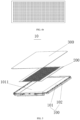
FIG. 1 is an exploded view of a battery tray according to an embodiment of the present disclosure. -
FIG. 2 is a structural exploded view of a first protection plate of a battery tray according to an embodiment of the present disclosure. -
FIG. 3 is a schematic structural diagram of a second protection plate of a battery tray according to an embodiment of the present disclosure. -
FIG. 4a is a schematic diagram of a second protection plate of a battery tray according to another embodiment of the present disclosure. -
FIG. 4b is a schematic diagram of a second protection plate of a battery tray according to another embodiment of the present disclosure. -
FIG. 5 is an exploded view of a battery tray from another perspective according to an embodiment of the present disclosure. -
FIG. 6 is a schematic diagram of an external object impacting a battery tray according to an embodiment of the present disclosure. - The reference numerals in the specification are as follow:
- 1. Battery pack;
- 10. Battery tray;
- 100. Tray body; 101. Tray bottom plate; 1011. Bottom plate groove; 102. Tray side beam;
- 200. Second protection plate; 201. Spaced through hole;
- 300. First protection plate; 301. High-strength plate; 302. Energy-absorbing plate;
- 20. Battery module; and
- 30. External object.
- Detailed description of the embodiments of present disclosure will be made in the following, and examples thereof are illustrated in the accompanying drawings, and same or similar reference numerals in all the accompanying drawings indicate same or similar components or components having same or similar functions. The embodiments described below with reference to the accompanying drawings are exemplary, and are intended to explain the present disclosure and cannot be construed as a limitation on the present disclosure.
- According to a first aspect, the present disclosure provides a
battery tray 10. As shown inFIG. 1 to FIG. 6 , thebattery tray 10 includes atray body 100, afirst protection plate 300, and asecond protection plate 200. Thetray body 100 includes atray bottom plate 101 and atray side beam 102 located on thetray bottom plate 101, and thetray side beam 102 and thetray bottom plate 101 enclose to form a battery accommodating cavity for accommodating abattery module 20 or a cell. One side of thesecond protection plate 200 is connected to thetray body 100, and the other side is connected to thefirst protection plate 300. Thefirst protection plate 300 includes an energy-absorbingplate 302 and high-strength plates 301 located on two sides of the energy-absorbingplate 302, the energy-absorbingplate 302 is in a cellular structure, and thefirst protection plate 300 is fixed onto thetray bottom plate 101. A wave impedance value of thesecond protection plate 200 is less than a wave impedance value of the high-strength plate 301. In the present disclosure, protection plates with different wave impedance values and structures are used, and it is defined that the wave impedance value of thesecond protection plate 200 is less than the wave impedance value of the high-strength plate 301 of thefirst protection plate 300. Therefore, when thebattery tray 10 is impacted by an obstacle, impact to thebattery module 20 in thebattery tray 10 can be reduced, thereby improving the anti-impact capability of thebattery tray 10. - Specifically, based on a principle of stress wave propagation, when an object is under an action of impact energy generated by an impact load, transverse stress wave propagation and longitudinal stress wave propagation are generated on a surface of the object to gradually propagate the impact energy from near to far. In a single material medium object, a stress wave generated by the impact energy is divided into transverse propagation and longitudinal propagation. When the surface of the object is impacted by an external object, an impact stress wave is propagated in a direction perpendicular to an impact force (namely, transverse propagation). A higher propagation speed of the stress wave indicates a higher spread speed of the impact energy in this direction, and spread of the impact energy at an impact point is converted from point spreading to surface spreading. When the surface of the object is impacted by the external object, the impact stress wave is propagated in a direction parallel to the impact force (namely, longitudinal propagation). The propagation is gradually attenuated as an increase in a propagation distance, a greater thickness of a material indicates a better protection effect, and the essence of propagation of the impact stress wave in the material is propagation of vibration of particles of the material led out by the external force from far to near. Damping of the material causes attenuation of the vibration of the particles of the material, and the propagation of the stress wave in the material is attenuated, and the material has a good anti-vibration capability. Further, greater damping of the material indicates greater attenuation of propagation of the stress wave.
- Therefore, based on the foregoing principle, in the present disclosure, the protection plates of the
battery tray 10 are divided into two types of protection plates, namely, thefirst protection plate 300 and thesecond protection plate 200. As shown inFIG. 2 , thefirst protection plate 300 includes an energy-absorbingplate 302 and high-strength plates 301 located on two sides of the energy-absorbingplate 302. In the present disclosure, an outermost protection plate of thebattery tray 10 is designed to thefirst protection plate 300 in a "sandwich structure", a protection capability of an outermost layer of thebattery tray 10 can be improved, costs and a weight of the tray can be further reduced, and energy density of abattery pack 1 can be improved. As can be known from the principle of stress wave propagation in an object, in the present disclosure, the anti-impact capability and protection capability of the protection plate are improved by limiting the structure of thefirst protection plate 300. In the structure design that thefirst protection plate 300 is designed to a "sandwich structure", namely, the high-strength plate 301, the energy-absorbingplate 302, and the high-strength plate 301, the outermost high-strength plate and the innermost high-strength plate 301 can reduce transverse propagation of the impact stress wave, the intermediate energy-absorbingplate 302 can further increase the entire thickness of thefirst protection plate 300 to further limit propagation of the impact stress wave, and the intermediate energy-absorbingplate 302 is designed to be cellular to further attenuate the impact. Specifically, the intermediate energy-absorbingplate 302 is designed to be cellular, causing the energy-absorbingplate 302 to have a strong deformation capability. When the impact stress wave is propagated from the high-strength plate 301 to the energy-absorbingplate 302, the cellular energy-absorbingplate 302 is deformed due to propagated impact of the impact stress wave, absorbs energy of the impact stress wave, and accelerates propagation attenuation of the impact stress wave. - In an embodiment of the present disclosure, it is defined that the wave impedance value of the
second protection plate 200 is less than the wave impedance value of the high-strength plate 301. In an embodiment of the present disclosure, the mentioned wave impedance value is related to a density of a material and a propagation speed of a stress wave in the material. A calculation formula thereof is: σ = ρ × C; where σ represents a wave impedance value of a medium (material); ρ represents a density of the medium (material); and C represents a propagation speed of a stress wave in the medium (material). When the impact stress wave runs through a material (incident medium) with high wave impedance into a material (transmission medium) with low wave impedance, a ratio of the wave impedance of the incident medium to the wave impedance of the transmission medium is n. Incident and transmission principles of the stress wave on different medium surfaces are as follows:


- In the foregoing formulas, n, F, and T are calculated according to the following formulas.


- (ρ 1 C 1)1 is a wave impedance value of the incident medium; (ρ 2 C 2)2 is a wave impedance value of the transmission medium; a ratio of the two values is n; F is a reflection coefficient, and T is a transmission coefficient; σ1 is a stress value of an incident wave; σT is a wave stress value of a transmission wave; and σR is a stress value of a reflected wave.
- As can be known from
Formula 1 to Formula 7, when the wave impedance ratio n is greater than 1, namely, when the wave impedance of the incident medium is greater than the wave impedance of the transmission medium, the reflection coefficient F is negative, which indicates that a reflected wave of the incident medium and the incident wave are in reverse directions, and the incident medium reflects a part of the stress value. When the transmission coefficient T is less than 1, it indicates that the stress value of the transmission wave is less than the stress value of the incident wave, and a larger value of n indicates a smaller stress value of the transmission wave. Therefore, when the stress wave is propagated from a medium with a large wave impedance value to a medium with a small wave impedance value, the stress wave propagated into the medium with a small wave impedance value becomes smaller. Therefore, In an embodiment of the present disclosure, by defining that the wave impedance value of the high-strength plate 301 is greater than the wave impedance value of thesecond protection plate 200, after anexternal object 30 impacts thebattery tray 10, it is ensured that propagation of the stress wave can be further reduced. - As can be known from the embodiments of the present disclosure, in the present disclosure, the
first protection plate 300 is arranged, and the structure of thefirst protection plate 300 is designed to a "sandwich structure", namely, the high-strength plate 301, the energy-absorbingplate 302, and the high-strength plate 301, and spreading of the impact stress wave can be preferentially reduced. In addition, the structure of the energy-absorbingplate 302 is designed to a "cellular" structure, thereby further improving absorption of thefirst protection plate 300 for the impact stress wave of theexternal object 30. When the impact stress wave of theexternal object 30 impacting thebattery tray 10 runs through thefirst protection plate 300, the residual impact stress wave can be further reduced after being spread to thesecond protection plate 200. In addition, thesecond protection plate 200 has a specific thickness, and propagation of the impact stress wave can be further reduced after the impact stress wave is propagated to thebattery module 20. Therefore, influence of the external impact to thebattery module 20 is reduced layer by layer. Compared with thebattery tray 10 in the related art, thebattery tray 10 In an embodiment of the present disclosure can achieve a better protection effect when impacted by theexternal object 30. - In an embodiment of the present disclosure, as shown in
FIG. 6 , when thebattery tray 10 is impacted by a foreign object from the bottom portion, a transmission direction of an impact stress is: the high-strength plate 301→the energy-absorbingplate 302→the high-strength plate 301→thesecond protection plate 200. First, the high-strength plate 301 has specific hardness and toughness, causing the surface of thefirst protection plate 300 to be not damaged. The energy-absorbingplate 302 is then deformed to absorb energy, the next layer of high-strength plate 301 prevents thefirst protection plate 300 from being penetrated, and thesecond protection plate 200 finally can spread remaining energy of energy at a point in a form of a stress wave. In this way, energy at a local point can be spread to a large surface, thereby reducing maximum deformation of the tray and protecting a battery cell. - Further, In an embodiment of the present disclosure, a material of the high-
strength plate 301 is at least one of PP glass fiber, resin glass fiber, or base fabric. A material of the energy-absorbingplate 302 is at least one of PP, PE, or metal. According to the present disclosure, the strength and protection capability of thebattery tray 10 are further improved by limiting the materials of the high-strength plate 301 and the energy-absorbingplate 302. Specifically, when the material of the high-strength plate 301 is PP glass fiber (or may be another material described above), the PP glass fiber layer plays a function of preventing the PP glass fiber plate from being penetrated when thefirst protection plate 300 is impacted. - Further, In an embodiment of the present disclosure, a material of the
second protection plate 200 is a foaming material. An objective of selecting the foaming material lies in that a plurality of pores are provided inside the material, and a texture of the material is softer than that of metal. Therefore, when the material is impacted, an impact force is spread in a form of a stress wave to spread the force. Optionally, the material of thesecond protection plate 200 is polyurethane. - In an embodiment of the present disclosure, to further reduce costs of the
battery tray 10, alightweight battery tray 10 is implemented. Thesecond protection plate 200 is provided with a plurality of spaced throughholes 201, a length of each of the spaced throughholes 201 ranges from 0 mm to 100 mm, and a distance between two adjacent spaced throughholes 201 ranges from 50 mm to 100 mm. Specifically, as shown inFIG. 3 , a length b of each of the spaced throughholes 201 ranges from 0 mm to 100 mm, and a distance a between two adjacent spaced throughholes 201 ranges from 50 mm to 100 mm. A direction of the length of spaced throughhole 201 is not specifically limited and a shape of the spaced throughhole 201 is also not limited. As shown inFIG. 3, FIG. 4a , andFIG. 4b , the spaced throughhole 201 may be in a shape of a rectangle, a square, or a circle. In addition, a quantity of the spaced throughholes 201 is also not limited. By providing the spaced throughholes 201 in thesecond protection plate 200, and limiting the length and arrangement positions of the spaced through holes 201 (namely, limiting the distance between two adjacent spaced through holes 201), the bottom protection requirement of thebattery tray 10 on thesecond protection plate 200 is implemented, and costs of thesecond protection plate 200 is further reduced, thereby implementing a lightweight design of thebattery tray 10. - In addition, providing the spaced through
holes 201 in thesecond protection plate 200 can further improve the protection capability of thebattery tray 10. Specifically, when thesecond protection plate 200 is provided with the plurality of spaced throughholes 201 provided at intervals, after the external object impacts thefirst protection plate 300, if a stress propagated from thefirst protection plate 300 to thesecond protection plate 200 is exactly located in the spaced throughholes 201, since no medium is in the spaced throughholes 201, the impact stress may be spread to thesecond protection plate 200 on two sides of the spaced throughholes 201, namely, spread from one stress propagation point to two stress propagation surfaces, thereby improving the propagation efficiency of the stress wave and improving the protection capability of thebattery tray 10. In the related art, in thebattery tray 10, the stress wave is spread from one force bearing point to one force bearing surface. In an embodiment of the present disclosure, by providing the spaced throughholes 201 in thesecond protection plate 200, the stress wave is spread from one force bearing point to two force bearing surfaces, thereby improving the efficiency of transverse propagation of the stress wave in thesecond protection plate 200, and further improving the protection capability of thebattery tray 10. - To further improve the protection capability of the
second protection plate 200, thesecond protection plate 200 defines that the length b of the spaced throughhole 201 ranges from 25 mm to 50 mm. Specifically, as can be seen from a ball strike test performed on thebattery tray 10 In an embodiment of the present disclosure (ball strike test: an impact head with a diameter ϕ of 20 mm and a weight of 10 kg is used to strike an external object at a speed of 5 m/s to impact the second protection plate 200), it is indicated through data of the test that, after thebattery tray 10 is provided with thesecond protection plate 200 with the foregoing spaced through holes, a recess of thebattery tray 10 after the ball strike test is small and hard to measure. A recess of abattery tray 10 without a groove is 2.1 mm. As can be known from the above, after the spaced throughholes 201 with the predetermined gap are provided in thesecond protection plate 200, the protection capability of the second protection plate is further improved, and the lightweight design of thebattery tray 10 is implemented and the energy density of thebattery pack 1 is improved. - In an embodiment of the present disclosure, as shown in
FIG. 5 , thetray body 100 includes atray bottom plate 101. Thetray bottom plate 101 is provided with abottom plate groove 1011, and thesecond protection plate 200 is arranged in thebottom plate groove 1011. In addition, thesecond protection plate 200 and thefirst protection plate 300 may be connected to thetray body 100 through an adhesive. Specifically, one side of thesecond protection plate 200 is bonded to thebottom plate groove 1011 of thetray bottom plate 101, and the other side of thesecond protection plate 200 is bonded to thefirst protection plate 300. In an embodiment of the present disclosure, if connection is performed through an insulating adhesive, thesecond protection plate 200 and thefirst protection plate 300 may be connected to thetray body 100 in a better manner, and the protection capability of thebattery tray 10 can also be improved, thereby effectively alleviating the impact force on the tray and further reducing influence on thebattery module 20 or the cell. In an embodiment of the present disclosure, arranging thesecond protection plate 200 in the groove of thebattery tray 10 further implements the lightweight design of thebattery tray 10. Further, thefirst protection plate 300 covers thebottom plate groove 1011 and is fixed onto thetray bottom plate 101 through rivets. - According to a second aspect, the present disclosure discloses a
battery pack 1. Thebattery pack 1 includes thebattery tray 10 described above and a plurality ofbattery modules 20 or cells, and the plurality ofbattery modules 20 or cells are located in the battery accommodating cavity. - According to a third aspect, the present disclosure discloses an electric vehicle, and the electric vehicle is provided with the
battery pack 1 described above. - In the description of the present disclosure, it should be understood that, orientation or position relationships indicated by terms such as "center", "longitudinal", "transverse", "length", "width", "thickness", "up", "down", "front", "rear", "left", "right", "vertical", "horizontal", "top", "bottom", "inner", "outer", "clockwise", "counterclockwise", "axial", "radial", and "circumferential" are orientation or position relationship shown based on the accompanying drawings, and are merely used for describing the present disclosure and simplifying the description, rather than indicating or implying that the indicated apparatus or element should have a particular orientation or be constructed and operated in a particular orientation, and therefore, should not be construed as a limitation on the present disclosure.
- In addition, the terms "first" and "second" are used merely for the purpose of description, and shall not be construed as indicating or implying relative importance or implying a quantity of indicated technical features. Therefore, a feature defined by "first" or "second" may explicitly indicate or implicitly include at least one of the features. In the description of the present disclosure, "a plurality of" means at least two, for example, two, three, and the like, unless otherwise explicitly and specifically defined.
- In the present disclosure, unless otherwise explicitly specified and defined, terms such as "mounted", "connected", "fixed" should be understood in broad sense. For example, the connection may be a fixed connection, a detachable connection, or an integral connection; or the connection may be a mechanical connection or an electrical connection; or the connection may be a direct connection, an indirect connection through an intermediary, or internal communication between two elements or mutual action relationship between two elements, unless otherwise specified explicitly. The specific meanings of the above terms in the present disclosure may be understood according to specific circumstances for a person of ordinary skill in the art.
- In the description of this specification, the description of reference terms such as "one embodiment", "some embodiments", "example", "specific example", or "some examples" means that specific features, structures, materials, or characteristics described in combination with the embodiment or example are included in at least one embodiment or example of the present disclosure. In this specification, exemplary description of the foregoing terms does not necessarily refer to a same embodiment or example. Besides, the specific features, structures, materials, or characteristics that are described may be combined in proper manners in any one or more embodiments or examples. In addition, a person skilled in the art may integrate or combine different embodiments or examples described in this specification and features of the different embodiments or examples provided that they are not contradictory to each other.
- Although the embodiments of the present disclosure have been shown and described above, it may be understood that the above embodiments are exemplary and should not be construed as a limitation on the present disclosure, and a person of ordinary skill in the art may make changes, modifications, replacements, and variations to the above embodiments within the scope of the present disclosure.
Claims (10)
- A battery tray comprising:a tray body, wherein the tray body comprises a tray bottom plate and a tray side beam located on the tray bottom plate, and the tray side beam and the tray bottom plate enclose to form a battery accommodating cavity for accommodating a battery module or a cell;a first protection plate, wherein the first protection plate comprises an energy-absorbing plate and high-strength plates located on two sides of the energy-absorbing plate, the energy-absorbing plate is in a cellular structure, and the first protection plate is fixed onto the tray bottom plate; anda second protection plate, wherein one side of the second protection plate is connected to the first protection plate, the other side is connected to the tray body, and a wave impedance value of the second protection plate is less than a wave impedance value of the high-strength plate.
- The battery tray according to claim 1, wherein a material of the high-strength plate is PP glass fiber, resin glass fiber, or base fabric; and a material of the energy-absorbing plate is PP, PE, or metal.
- The battery tray according to claim 1, wherein a material of the second protection plate is a foaming material.
- The battery tray according to claim 3, wherein the material of the second protection plate is polyurethane.
- The battery tray according to any one of claims 1 to 4, wherein the second protection plate is provided with a plurality of spaced through holes, a length of each of the spaced through holes ranges from 0 mm to 100 mm, and a distance between two adjacent spaced through holes ranges from 50 mm to 100 mm.
- The battery tray according to claim 5, wherein the length of each of the spaced through holes ranges from 25 mm to 50 mm.
- The battery tray according to any one of claims 1 to 6, wherein a side of the tray bottom plate away from the tray side beam is provided with a bottom plate groove, and the second protection plate is arranged in the bottom plate groove.
- The battery tray according to claim 7, wherein one side of the second protection plate is bonded to the bottom plate groove of the tray bottom plate, and the other side is bonded to the first protection plate; and
the first protection plate covers the bottom plate groove and is fixed onto the tray bottom plate. - A battery pack, comprising: the battery tray according to any one of claims 1 to 8 and a plurality of battery modules or cells, wherein the plurality of battery modules or cells are located in the battery accommodating cavity.
- An electric vehicle, comprising the battery pack according to claim 9.
Applications Claiming Priority (2)
| Application Number | Priority Date | Filing Date | Title |
|---|---|---|---|
| CN202011346094.XA CN114552095A (en) | 2020-11-25 | 2020-11-25 | Battery tray, battery package and electric automobile |
| PCT/CN2021/092464 WO2022110652A1 (en) | 2020-11-25 | 2021-05-08 | Battery tray, battery pack, and electric vehicle |
Publications (2)
| Publication Number | Publication Date |
|---|---|
| EP4216351A1 true EP4216351A1 (en) | 2023-07-26 |
| EP4216351A4 EP4216351A4 (en) | 2024-03-20 |
Family
ID=81659467
Family Applications (1)
| Application Number | Title | Priority Date | Filing Date |
|---|---|---|---|
| EP21896167.0A Pending EP4216351A4 (en) | 2020-11-25 | 2021-05-08 | Battery tray, battery pack, and electric vehicle |
Country Status (7)
| Country | Link |
|---|---|
| US (1) | US20230275298A1 (en) |
| EP (1) | EP4216351A4 (en) |
| JP (1) | JP2023550801A (en) |
| KR (1) | KR20230078745A (en) |
| CN (1) | CN114552095A (en) |
| CA (1) | CA3199864A1 (en) |
| WO (1) | WO2022110652A1 (en) |
Families Citing this family (11)
| Publication number | Priority date | Publication date | Assignee | Title |
|---|---|---|---|---|
| CN217281026U (en) * | 2022-06-08 | 2022-08-23 | 宁德时代新能源科技股份有限公司 | Battery box, battery and power consumption device |
| CN115847950A (en) * | 2022-08-05 | 2023-03-28 | 广州市三泰汽车内饰材料有限公司 | New energy automobile battery soft package protective partition plate and manufacturing process thereof |
| CN115431735A (en) * | 2022-09-29 | 2022-12-06 | 东风汽车集团股份有限公司 | Battery package protective structure and car of car |
| EP4468481A4 (en) * | 2022-09-30 | 2025-04-16 | Contemporary Amperex Technology (Hong Kong) Limited | Battery box, battery, electric device, and method and device for manufacturing box |
| CN116014332A (en) * | 2022-12-05 | 2023-04-25 | 广汽埃安新能源汽车股份有限公司 | A processing method for lower floor assembly, battery pack, electric vehicle and battery pack |
| CN115946513B (en) * | 2022-12-06 | 2026-05-01 | 吴伯明 | Electric automobile with battery composite material protection function |
| CN115939643A (en) * | 2023-01-30 | 2023-04-07 | 广汽埃安新能源汽车股份有限公司 | Battery box, battery pack and electrical equipment |
| CN116031562B (en) * | 2023-03-28 | 2023-07-04 | 合肥召洋电子科技有限公司 | A battery pack installation structure for an energy storage battery |
| KR20250037895A (en) * | 2023-09-11 | 2025-03-19 | 주식회사 엘지에너지솔루션 | Battery pack |
| CN222440746U (en) * | 2024-03-21 | 2025-02-07 | 惠州亿纬锂能股份有限公司 | Composite bottom guard plate, battery and electrical equipment |
| CN118254561B (en) * | 2024-05-29 | 2024-07-23 | 山西承信新能源科技装备有限公司 | Range-extending type hybrid power mining trackless rubber-tyred vehicle |
Family Cites Families (14)
| Publication number | Priority date | Publication date | Assignee | Title |
|---|---|---|---|---|
| CN104647823B (en) * | 2013-11-25 | 2017-01-18 | 中国兵器工业第五二研究所 | Shock-resistant energy-absorbing material and preparation method thereof |
| CN107719137A (en) * | 2016-08-10 | 2018-02-23 | 深圳市沃特玛电池有限公司 | A kind of electric automobile chassis structure |
| US10483510B2 (en) * | 2017-05-16 | 2019-11-19 | Shape Corp. | Polarized battery tray for a vehicle |
| CN109216605B (en) * | 2017-06-30 | 2020-12-25 | 比亚迪股份有限公司 | Battery tray, battery pack assembly and vehicle with same |
| CN109216601B (en) * | 2017-06-30 | 2020-12-25 | 比亚迪股份有限公司 | Battery tray and battery pack assembly with same |
| JP7123537B2 (en) * | 2017-09-19 | 2022-08-23 | 株式会社Fts | battery case |
| JP2019110003A (en) * | 2017-12-18 | 2019-07-04 | トヨタ自動車株式会社 | Battery case |
| CN208489252U (en) * | 2018-05-24 | 2019-02-12 | 深圳腾势新能源汽车有限公司 | battery tray |
| CN208423007U (en) * | 2018-06-25 | 2019-01-22 | 北京新能源汽车股份有限公司 | Battery pack base, battery pack and electric automobile |
| EP3919313A1 (en) * | 2018-09-20 | 2021-12-08 | LG Hausys, Ltd. | Lower protecting plate of battery module for electric car |
| CN113613926B (en) * | 2018-11-20 | 2023-08-11 | 泰普爱复合材料股份有限公司 | Composite battery case |
| CN209544447U (en) * | 2019-03-15 | 2019-10-25 | 北京新能源汽车股份有限公司蓝谷动力系统分公司 | Bottom protection plate assembly and battery pack |
| CN210821795U (en) * | 2019-06-27 | 2020-06-23 | 安徽新华学院 | A partition type car battery tray rack |
| US10707462B1 (en) * | 2019-08-28 | 2020-07-07 | Manaflex, Llc | Intracellular device for lithium ion batteries |
-
2020
- 2020-11-25 CN CN202011346094.XA patent/CN114552095A/en active Pending
-
2021
- 2021-05-08 EP EP21896167.0A patent/EP4216351A4/en active Pending
- 2021-05-08 WO PCT/CN2021/092464 patent/WO2022110652A1/en not_active Ceased
- 2021-05-08 KR KR1020237014280A patent/KR20230078745A/en active Pending
- 2021-05-08 CA CA3199864A patent/CA3199864A1/en active Pending
- 2021-05-08 JP JP2023532121A patent/JP2023550801A/en active Pending
-
2023
- 2023-05-08 US US18/144,518 patent/US20230275298A1/en active Pending
Also Published As
| Publication number | Publication date |
|---|---|
| KR20230078745A (en) | 2023-06-02 |
| EP4216351A4 (en) | 2024-03-20 |
| WO2022110652A1 (en) | 2022-06-02 |
| JP2023550801A (en) | 2023-12-05 |
| CN114552095A (en) | 2022-05-27 |
| US20230275298A1 (en) | 2023-08-31 |
| CA3199864A1 (en) | 2022-06-02 |
Similar Documents
| Publication | Publication Date | Title |
|---|---|---|
| US20230275298A1 (en) | Battery tray, battery pack, and electric vehicle | |
| US10826035B2 (en) | Fixing frame and battery pack | |
| CN108502031B (en) | A car door sill with microcell filling layer | |
| EP3473966B1 (en) | Method for mitigating stress waves resulting from a blast or impact | |
| CN110360259B (en) | Vibration reduction buffer structure applied to sensitive device and missile-borne equipment | |
| CN218334082U (en) | Bottom guard plate, battery box and battery device | |
| US20160229308A1 (en) | Battery Enclosure Having T-Shaped Guides on the Outer Surface for Stiffeners and Impact Absorbing Elements | |
| KR20200059363A (en) | Composite material layer, structural integrated fuel tank and aircraft comprising same | |
| ITMI950970A1 (en) | COMPOSITE MATERIAL STRUCTURE SUITABLE TO ABSORB AND DISSIPATE THE POWER OF ELECTROMAGNETIC RADIATION IN PARTICULAR ACCIDENT | |
| WO2025195413A1 (en) | Battery pack and electrical device | |
| CN222146430U (en) | Battery pack multi-layer protection structure, battery pack guard plate, battery pack and electrical equipment | |
| CN220492064U (en) | Battery pack and electricity utilization device | |
| CN217387353U (en) | A fender structure and a vehicle having the same | |
| CN214068804U (en) | Battery cell protection structure and vertical battery pack | |
| CN214043914U (en) | Novel lithium battery triaxial shock attenuation nickel sheet | |
| CN218827537U (en) | Protective structures, battery packs and vehicles | |
| CN208634257U (en) | A kind of adaptive high overload impact isolating structure based on lock energy Meta Materials | |
| CN219780588U (en) | Explosion-proof assembly and commercial power data acquisition unit | |
| CN224249184U (en) | Outdoor cabinet base of energy storage and outdoor cabinet of energy storage | |
| CN223520760U (en) | The undercarriage structure of a car and vehicles with it | |
| CN222698457U (en) | Energy absorbing structure for improving the side impact resistance of automobile and automobile | |
| CN220753611U (en) | Box, battery and power consumption device | |
| CN215644720U (en) | Battery cell supporting structure of battery module, battery module and battery pack | |
| CN215377540U (en) | Lithium battery with good damping performance | |
| CN222638963U (en) | Noise absorption electromagnetic film |
Legal Events
| Date | Code | Title | Description |
|---|---|---|---|
| STAA | Information on the status of an ep patent application or granted ep patent |
Free format text: STATUS: THE INTERNATIONAL PUBLICATION HAS BEEN MADE |
|
| PUAI | Public reference made under article 153(3) epc to a published international application that has entered the european phase |
Free format text: ORIGINAL CODE: 0009012 |
|
| STAA | Information on the status of an ep patent application or granted ep patent |
Free format text: STATUS: REQUEST FOR EXAMINATION WAS MADE |
|
| 17P | Request for examination filed |
Effective date: 20230417 |
|
| AK | Designated contracting states |
Kind code of ref document: A1 Designated state(s): AL AT BE BG CH CY CZ DE DK EE ES FI FR GB GR HR HU IE IS IT LI LT LU LV MC MK MT NL NO PL PT RO RS SE SI SK SM TR |
|
| REG | Reference to a national code |
Ref country code: DE Ref legal event code: R079 Free format text: PREVIOUS MAIN CLASS: H01M0050244000 Ipc: H01M0050204000 |
|
| DAV | Request for validation of the european patent (deleted) | ||
| DAX | Request for extension of the european patent (deleted) | ||
| A4 | Supplementary search report drawn up and despatched |
Effective date: 20240216 |
|
| RIC1 | Information provided on ipc code assigned before grant |
Ipc: H01M 50/258 20210101ALI20240212BHEP Ipc: H01M 50/249 20210101ALI20240212BHEP Ipc: H01M 50/244 20210101ALI20240212BHEP Ipc: H01M 50/242 20210101ALI20240212BHEP Ipc: H01M 50/24 20210101ALI20240212BHEP Ipc: H01M 50/233 20210101ALI20240212BHEP Ipc: H01M 50/231 20210101ALI20240212BHEP Ipc: H01M 50/227 20210101ALI20240212BHEP Ipc: H01M 50/224 20210101ALI20240212BHEP Ipc: H01M 50/209 20210101ALI20240212BHEP Ipc: H01M 50/204 20210101AFI20240212BHEP |
|
| STAA | Information on the status of an ep patent application or granted ep patent |
Free format text: STATUS: EXAMINATION IS IN PROGRESS |
|
| 17Q | First examination report despatched |
Effective date: 20260108 |