EP4216342A1 - Battery module, and battery pack and vehicle comprising same - Google Patents
Battery module, and battery pack and vehicle comprising same Download PDFInfo
- Publication number
- EP4216342A1 EP4216342A1 EP22820537.3A EP22820537A EP4216342A1 EP 4216342 A1 EP4216342 A1 EP 4216342A1 EP 22820537 A EP22820537 A EP 22820537A EP 4216342 A1 EP4216342 A1 EP 4216342A1
- Authority
- EP
- European Patent Office
- Prior art keywords
- battery
- cell
- cooling liquid
- bus bar
- bar frame
- Prior art date
- Legal status (The legal status is an assumption and is not a legal conclusion. Google has not performed a legal analysis and makes no representation as to the accuracy of the status listed.)
- Pending
Links
Images





Classifications
-
- H—ELECTRICITY
- H01—ELECTRIC ELEMENTS
- H01M—PROCESSES OR MEANS, e.g. BATTERIES, FOR THE DIRECT CONVERSION OF CHEMICAL ENERGY INTO ELECTRICAL ENERGY
- H01M10/00—Secondary cells; Manufacture thereof
- H01M10/60—Heating or cooling; Temperature control
- H01M10/65—Means for temperature control structurally associated with the cells
- H01M10/656—Means for temperature control structurally associated with the cells characterised by the type of heat-exchange fluid
- H01M10/6567—Liquids
-
- H—ELECTRICITY
- H01—ELECTRIC ELEMENTS
- H01M—PROCESSES OR MEANS, e.g. BATTERIES, FOR THE DIRECT CONVERSION OF CHEMICAL ENERGY INTO ELECTRICAL ENERGY
- H01M50/00—Constructional details or processes of manufacture of the non-active parts of electrochemical cells other than fuel cells, e.g. hybrid cells
- H01M50/20—Mountings; Secondary casings or frames; Racks, modules or packs; Suspension devices; Shock absorbers; Transport or carrying devices; Holders
- H01M50/204—Racks, modules or packs for multiple batteries or multiple cells
- H01M50/207—Racks, modules or packs for multiple batteries or multiple cells characterised by their shape
- H01M50/211—Racks, modules or packs for multiple batteries or multiple cells characterised by their shape adapted for pouch cells
-
- H—ELECTRICITY
- H01—ELECTRIC ELEMENTS
- H01M—PROCESSES OR MEANS, e.g. BATTERIES, FOR THE DIRECT CONVERSION OF CHEMICAL ENERGY INTO ELECTRICAL ENERGY
- H01M10/00—Secondary cells; Manufacture thereof
- H01M10/42—Methods or arrangements for servicing or maintenance of secondary cells or secondary half-cells
- H01M10/425—Structural combination with electronic components, e.g. electronic circuits integrated to the outside of the casing
-
- H—ELECTRICITY
- H01—ELECTRIC ELEMENTS
- H01M—PROCESSES OR MEANS, e.g. BATTERIES, FOR THE DIRECT CONVERSION OF CHEMICAL ENERGY INTO ELECTRICAL ENERGY
- H01M10/00—Secondary cells; Manufacture thereof
- H01M10/42—Methods or arrangements for servicing or maintenance of secondary cells or secondary half-cells
- H01M10/48—Accumulators combined with arrangements for measuring, testing or indicating the condition of cells, e.g. the level or density of the electrolyte
-
- H—ELECTRICITY
- H01—ELECTRIC ELEMENTS
- H01M—PROCESSES OR MEANS, e.g. BATTERIES, FOR THE DIRECT CONVERSION OF CHEMICAL ENERGY INTO ELECTRICAL ENERGY
- H01M10/00—Secondary cells; Manufacture thereof
- H01M10/42—Methods or arrangements for servicing or maintenance of secondary cells or secondary half-cells
- H01M10/48—Accumulators combined with arrangements for measuring, testing or indicating the condition of cells, e.g. the level or density of the electrolyte
- H01M10/482—Accumulators combined with arrangements for measuring, testing or indicating the condition of cells, e.g. the level or density of the electrolyte for several batteries or cells simultaneously or sequentially
-
- H—ELECTRICITY
- H01—ELECTRIC ELEMENTS
- H01M—PROCESSES OR MEANS, e.g. BATTERIES, FOR THE DIRECT CONVERSION OF CHEMICAL ENERGY INTO ELECTRICAL ENERGY
- H01M10/00—Secondary cells; Manufacture thereof
- H01M10/42—Methods or arrangements for servicing or maintenance of secondary cells or secondary half-cells
- H01M10/48—Accumulators combined with arrangements for measuring, testing or indicating the condition of cells, e.g. the level or density of the electrolyte
- H01M10/486—Accumulators combined with arrangements for measuring, testing or indicating the condition of cells, e.g. the level or density of the electrolyte for measuring temperature
-
- H—ELECTRICITY
- H01—ELECTRIC ELEMENTS
- H01M—PROCESSES OR MEANS, e.g. BATTERIES, FOR THE DIRECT CONVERSION OF CHEMICAL ENERGY INTO ELECTRICAL ENERGY
- H01M10/00—Secondary cells; Manufacture thereof
- H01M10/60—Heating or cooling; Temperature control
- H01M10/64—Heating or cooling; Temperature control characterised by the shape of the cells
- H01M10/647—Prismatic or flat cells, e.g. pouch cells
-
- H—ELECTRICITY
- H01—ELECTRIC ELEMENTS
- H01M—PROCESSES OR MEANS, e.g. BATTERIES, FOR THE DIRECT CONVERSION OF CHEMICAL ENERGY INTO ELECTRICAL ENERGY
- H01M10/00—Secondary cells; Manufacture thereof
- H01M10/60—Heating or cooling; Temperature control
- H01M10/65—Means for temperature control structurally associated with the cells
- H01M10/655—Solid structures for heat exchange or heat conduction
- H01M10/6551—Surfaces specially adapted for heat dissipation or radiation, e.g. fins or coatings
-
- H—ELECTRICITY
- H01—ELECTRIC ELEMENTS
- H01M—PROCESSES OR MEANS, e.g. BATTERIES, FOR THE DIRECT CONVERSION OF CHEMICAL ENERGY INTO ELECTRICAL ENERGY
- H01M10/00—Secondary cells; Manufacture thereof
- H01M10/60—Heating or cooling; Temperature control
- H01M10/65—Means for temperature control structurally associated with the cells
- H01M10/655—Solid structures for heat exchange or heat conduction
- H01M10/6554—Rods or plates
- H01M10/6555—Rods or plates arranged between the cells
-
- H—ELECTRICITY
- H01—ELECTRIC ELEMENTS
- H01M—PROCESSES OR MEANS, e.g. BATTERIES, FOR THE DIRECT CONVERSION OF CHEMICAL ENERGY INTO ELECTRICAL ENERGY
- H01M10/00—Secondary cells; Manufacture thereof
- H01M10/60—Heating or cooling; Temperature control
- H01M10/65—Means for temperature control structurally associated with the cells
- H01M10/655—Solid structures for heat exchange or heat conduction
- H01M10/6556—Solid parts with flow channel passages or pipes for heat exchange
-
- H—ELECTRICITY
- H01—ELECTRIC ELEMENTS
- H01M—PROCESSES OR MEANS, e.g. BATTERIES, FOR THE DIRECT CONVERSION OF CHEMICAL ENERGY INTO ELECTRICAL ENERGY
- H01M10/00—Secondary cells; Manufacture thereof
- H01M10/60—Heating or cooling; Temperature control
- H01M10/65—Means for temperature control structurally associated with the cells
- H01M10/656—Means for temperature control structurally associated with the cells characterised by the type of heat-exchange fluid
- H01M10/6561—Gases
- H01M10/6563—Gases with forced flow, e.g. by blowers
-
- H—ELECTRICITY
- H01—ELECTRIC ELEMENTS
- H01M—PROCESSES OR MEANS, e.g. BATTERIES, FOR THE DIRECT CONVERSION OF CHEMICAL ENERGY INTO ELECTRICAL ENERGY
- H01M50/00—Constructional details or processes of manufacture of the non-active parts of electrochemical cells other than fuel cells, e.g. hybrid cells
- H01M50/20—Mountings; Secondary casings or frames; Racks, modules or packs; Suspension devices; Shock absorbers; Transport or carrying devices; Holders
- H01M50/204—Racks, modules or packs for multiple batteries or multiple cells
- H01M50/207—Racks, modules or packs for multiple batteries or multiple cells characterised by their shape
- H01M50/209—Racks, modules or packs for multiple batteries or multiple cells characterised by their shape adapted for prismatic or rectangular cells
-
- H—ELECTRICITY
- H01—ELECTRIC ELEMENTS
- H01M—PROCESSES OR MEANS, e.g. BATTERIES, FOR THE DIRECT CONVERSION OF CHEMICAL ENERGY INTO ELECTRICAL ENERGY
- H01M50/00—Constructional details or processes of manufacture of the non-active parts of electrochemical cells other than fuel cells, e.g. hybrid cells
- H01M50/20—Mountings; Secondary casings or frames; Racks, modules or packs; Suspension devices; Shock absorbers; Transport or carrying devices; Holders
- H01M50/271—Lids or covers for the racks or secondary casings
-
- H—ELECTRICITY
- H01—ELECTRIC ELEMENTS
- H01M—PROCESSES OR MEANS, e.g. BATTERIES, FOR THE DIRECT CONVERSION OF CHEMICAL ENERGY INTO ELECTRICAL ENERGY
- H01M50/00—Constructional details or processes of manufacture of the non-active parts of electrochemical cells other than fuel cells, e.g. hybrid cells
- H01M50/50—Current conducting connections for cells or batteries
-
- H—ELECTRICITY
- H01—ELECTRIC ELEMENTS
- H01M—PROCESSES OR MEANS, e.g. BATTERIES, FOR THE DIRECT CONVERSION OF CHEMICAL ENERGY INTO ELECTRICAL ENERGY
- H01M50/00—Constructional details or processes of manufacture of the non-active parts of electrochemical cells other than fuel cells, e.g. hybrid cells
- H01M50/50—Current conducting connections for cells or batteries
- H01M50/502—Interconnectors for connecting terminals of adjacent batteries; Interconnectors for connecting cells outside a battery casing
-
- H—ELECTRICITY
- H01—ELECTRIC ELEMENTS
- H01M—PROCESSES OR MEANS, e.g. BATTERIES, FOR THE DIRECT CONVERSION OF CHEMICAL ENERGY INTO ELECTRICAL ENERGY
- H01M50/00—Constructional details or processes of manufacture of the non-active parts of electrochemical cells other than fuel cells, e.g. hybrid cells
- H01M50/50—Current conducting connections for cells or batteries
- H01M50/502—Interconnectors for connecting terminals of adjacent batteries; Interconnectors for connecting cells outside a battery casing
- H01M50/507—Interconnectors for connecting terminals of adjacent batteries; Interconnectors for connecting cells outside a battery casing comprising an arrangement of two or more busbars within a container structure, e.g. busbar modules
-
- H—ELECTRICITY
- H01—ELECTRIC ELEMENTS
- H01M—PROCESSES OR MEANS, e.g. BATTERIES, FOR THE DIRECT CONVERSION OF CHEMICAL ENERGY INTO ELECTRICAL ENERGY
- H01M50/00—Constructional details or processes of manufacture of the non-active parts of electrochemical cells other than fuel cells, e.g. hybrid cells
- H01M50/50—Current conducting connections for cells or batteries
- H01M50/569—Constructional details of current conducting connections for detecting conditions inside cells or batteries, e.g. details of voltage sensing terminals
-
- H—ELECTRICITY
- H01—ELECTRIC ELEMENTS
- H01M—PROCESSES OR MEANS, e.g. BATTERIES, FOR THE DIRECT CONVERSION OF CHEMICAL ENERGY INTO ELECTRICAL ENERGY
- H01M10/00—Secondary cells; Manufacture thereof
- H01M10/60—Heating or cooling; Temperature control
- H01M10/61—Types of temperature control
- H01M10/613—Cooling or keeping cold
-
- H—ELECTRICITY
- H01—ELECTRIC ELEMENTS
- H01M—PROCESSES OR MEANS, e.g. BATTERIES, FOR THE DIRECT CONVERSION OF CHEMICAL ENERGY INTO ELECTRICAL ENERGY
- H01M10/00—Secondary cells; Manufacture thereof
- H01M10/60—Heating or cooling; Temperature control
- H01M10/62—Heating or cooling; Temperature control specially adapted for specific applications
- H01M10/625—Vehicles
-
- H—ELECTRICITY
- H01—ELECTRIC ELEMENTS
- H01M—PROCESSES OR MEANS, e.g. BATTERIES, FOR THE DIRECT CONVERSION OF CHEMICAL ENERGY INTO ELECTRICAL ENERGY
- H01M2220/00—Batteries for particular applications
- H01M2220/20—Batteries in motive systems, e.g. vehicle, ship, plane
-
- H—ELECTRICITY
- H01—ELECTRIC ELEMENTS
- H01M—PROCESSES OR MEANS, e.g. BATTERIES, FOR THE DIRECT CONVERSION OF CHEMICAL ENERGY INTO ELECTRICAL ENERGY
- H01M50/00—Constructional details or processes of manufacture of the non-active parts of electrochemical cells other than fuel cells, e.g. hybrid cells
- H01M50/20—Mountings; Secondary casings or frames; Racks, modules or packs; Suspension devices; Shock absorbers; Transport or carrying devices; Holders
- H01M50/249—Mountings; Secondary casings or frames; Racks, modules or packs; Suspension devices; Shock absorbers; Transport or carrying devices; Holders specially adapted for aircraft or vehicles, e.g. cars or trains
-
- Y—GENERAL TAGGING OF NEW TECHNOLOGICAL DEVELOPMENTS; GENERAL TAGGING OF CROSS-SECTIONAL TECHNOLOGIES SPANNING OVER SEVERAL SECTIONS OF THE IPC; TECHNICAL SUBJECTS COVERED BY FORMER USPC CROSS-REFERENCE ART COLLECTIONS [XRACs] AND DIGESTS
- Y02—TECHNOLOGIES OR APPLICATIONS FOR MITIGATION OR ADAPTATION AGAINST CLIMATE CHANGE
- Y02E—REDUCTION OF GREENHOUSE GAS [GHG] EMISSIONS, RELATED TO ENERGY GENERATION, TRANSMISSION OR DISTRIBUTION
- Y02E60/00—Enabling technologies; Technologies with a potential or indirect contribution to GHG emissions mitigation
- Y02E60/10—Energy storage using batteries
Definitions
- the present disclosure relates to a battery module, and a battery pack and a vehicle including the same, and more specifically, to a battery module having a structure in which an insulating cooling liquid flowing into a module housing cools battery cells while flowing through a space between a cell wing portion of the battery cell and the module housing, and a battery pack and a vehicle including the same.
- the cooling performance is limited because the cooling water does not directly contact a battery cell but indirectly contacts the battery cell through a module housing that houses the battery cell.
- a cooling device such as a separate heatsink must be provided outside the module housing to form a flow path for cooling, the overall volume of the battery module is inevitably increased, which inevitably causes loss in terms of energy density.
- the present disclosure is designed to solve the problems of the related art, and therefore the present disclosure is directed to providing a battery module having a structure in which an insulating cooling liquid is introduced into the battery module and comes into direct contact with a battery cell to realize efficient cooling, and the cooling liquid introduced into the battery module may flow smoothly.
- the present disclosure has another object to prevent a sensing line and a temperature sensor provided for sensing the voltage and temperature of the battery cell from being damaged by an insulating cooling liquid flowing inside the battery module, and to enable accurate temperature measurement.
- the sensing assembly may be disposed on a top of the sub module.
- the sensing assembly may include a sensing line electrically connected to the plurality of battery cells and extending from one longitudinal end of the battery cells to the other longitudinal end.
- the sensing line may be interposed between a cell body portion of the battery cell and a cell wing portion folded toward the cell body portion.
- the sensing assembly may further include a temperature sensor mounted on the sensing line.
- the temperature sensor may be interposed between a cell body portion of the battery cell and a cell wing portion folded toward the cell body portion.
- the cooling fin may include a body contact portion interposed between adjacent battery cells, and a wing cover portion bent at any one of a top and bottom of the body contact portion to cover a cell wing portion of the battery cell.
- the sub module may include a front bus bar frame assembly coupled to one longitudinal side of the cell stack assembly; and a rear bus bar frame assembly coupled to the other longitudinal side of the cell stack assembly.
- the front bus bar frame assembly and the rear bus bar frame assembly may have a plurality of cooling liquid holes formed at a position corresponding to a cooling liquid flow path formed between the module housing and the cell wing portion of the battery cell and between the wing cover portion and the cell wing portion of the battery cell.
- An insulating cooling liquid introduced into the module housing through the inlet may pass through the cooling liquid hole formed in the front bus bar frame assembly and flow to the cooling liquid flow path.
- the insulating cooling liquid passing through the cooling liquid flow path may pass through the cooling liquid hole formed in the rear bus bar frame assembly and be discharged to the outside of the module housing through the outlet.
- a battery pack and a vehicle according to an embodiment of the present disclosure to solve the above problem comprises the battery module according to the present disclosure.
- the insulating cooling liquid flows into the battery module and directly contacts the battery cell, and the cooling liquid introduced into the battery module may flow smoothly, thereby allowing efficient and rapid cooling.
- the sensing line and the temperature sensor provided for sensing the voltage and temperature of the battery cell from being damaged by the insulating cooling liquid flowing inside the battery module, and to enable accurate temperature measurement by minimizing the influence of the insulating cooling liquid in measuring the temperature of the battery cell.
- the battery module includes a sub module 100, a module housing 200, a front sealing plate 300, a rear sealing plate 400 and a sensing assembly 800.
- the battery module may further include a front end plate 500 and/or a rear end plate 600 and/or a pair of terminal assemblies 700 in addition to the above-described components.
- the sub module 100 includes a cell stack assembly 110.
- the sub module 100 includes a front bus bar frame assembly 120A and a rear bus bar frame assembly 120B in addition to the cell stack assembly 110.
- the cell stack assembly 110 includes a plurality of battery cells 111.
- the cell stack assembly 110 may further include at least one cooling fin 112 interposed between adjacent battery cells 111 and/or at least one buffer pad 113 interposed between the adjacent battery cells 111.
- the plurality of battery cells 111 are stacked approximately in a vertical standing form on the ground (a side parallel to the X-Y plane) to form a single cell stack assembly 110.
- the cooling fin 112 and/or the buffer pad 113 are also stacked in a vertical standing form approximately perpendicular to the ground (surface parallel to the X-Y plane) together with the plurality of battery cells 111 to form a single cell stack assembly 110.
- a pouch-type battery cell having a pair of electrode leads 111a drawn out in opposite directions along the longitudinal direction (parallel to the X-axis) may be used.
- the cooling fin 112 includes a body contact portion 112a interposed between the battery cells 111 adjacent to each other, and a wing cover portion 112b bent at any one of the top and bottom of the body contact portion 112a to cover the cell wing portion W of the battery cell 111.
- the cooling fin 112 may further include a pair of fixing portions 112c formed at both ends in the longitudinal direction (parallel to the X-axis) of the wing cover portion 112b.
- an area in which an electrode assembly (not shown) is accommodated may be defined as the cell body portion B, and a region elongated along the longitudinal direction (parallel to the X-axis) of the battery module in the sealing area formed around the cell body portion B may be defined as the cell wing portion W.
- the body contact portion 112a is interposed between the cell body portions B of the pair of adjacent battery cells 111 and is in direct contact with the cell body portions B of the battery cells 111.
- the body contact portion 112a rapidly conducts heat generated from the cell body portion B of the battery cell 111 in the width direction of the cooling fin 112, that is, in the height direction (parallel to the Z-axis) of the battery module to move toward the wing cover portion 112b.
- the heat conducted toward the wing cover portion 112b is transferred along the longitudinal direction (parallel to the X-axis) of the battery module by the insulating cooling liquid flowing through the cooling liquid flow path P formed between the cell wing portion W of the battery cell 111 and the wing cover portion 112b of the cooling fin 112 and is discharged to the outside of the battery module.
- the wing cover portion 112b may also perform the function of absorbing the impact when external impact is applied so that the cell stack assembly 110 moves in the vertical direction (parallel to the Z-axis) within the module housing 200.
- This impact absorption function of the wing cover portion 112b may help prevent damage to the sensing line 810 and the temperature sensor 820 interposed between the cell wing portion W and the cell body portion B (see FIG. 13 ).
- the sensing assembly 800 including the sensing line 810 and the temperature sensor 820 will be described later in detail.
- the fixing portion 112c has a shape corresponding to a guide rib 121b to be described later. As the fixing portion 112c is coupled to the guide rib 121b, the fixing portion 112c guides the fastening between the cell stack assembly 110 including the cooling fin 112 and the bus bar frame assemblies 120A, 120B.
- the buffer pad 113 may be interposed between adjacent battery cells 111 to absorb volume expansion due to swelling of the battery cells 111.
- the front bus bar frame assembly 120A and the rear bus bar frame assembly 120B are coupled to one side and the other side in the longitudinal direction (parallel to the X axis) of the cell stack assembly 110, respectively, so that a plurality of battery cells 111 are electrically connected.
- the front bus bar frame assembly 120A and the rear bus bar frame assembly 120B have substantially the same structure except that the front bus bar frame assembly 120A is provided with the inner terminal 123 and the rear bus bar frame assembly 120B is not provided with the inner terminal 123. Accordingly, a detailed description of the specific structure of the rear bus bar frame assembly 120B will be omitted, and a detailed description of the specific structure of the front bus bar frame assembly 120A will be intensively described.
- the front bus bar frame assembly 120A includes a bus bar frame 121 and a plurality of bus bars 122.
- the front bus bar frame assembly 120A may further include a pair of inner terminals 123.
- the bus bar frame 121 covers one side of the cell stack assembly 110 in the longitudinal direction (parallel to the X-axis).
- the bus bar frame 121 has a plurality of cooling liquid holes 121a.
- the cooling liquid hole 121a functions as a passage so that the insulating cooling liquid introduced into the module housing 200 through the inlet P1 provided in the front sealing plate 300 may flow toward the cell stack assembly 110 through the bus bar frame 121.
- the cooling liquid flow path P is formed between the module housing 200 and the cell wing portion W.
- the cooling liquid flow path P may be formed between the wing cover portion 112b and the cell wing portion W in addition to between the module housing 200 and the cell wing portion W.
- the cooling liquid hole 121a may be formed between the module housing 200 and the cell wing portion W.
- the cooling liquid hole 121a may be formed at a position corresponding to the cooling liquid flow path P formed between the wing cover portion 112b and the cell wing portion W.
- the insulating cooling liquid introduced toward the cell stack assembly 110 through the cooling liquid hole 121a formed in the front bus bar frame assembly 120A is flowed toward the rear bus bar frame assembly 120B through the cooling liquid flow path P along the arrow (see FIGS. 5 and 6 ).
- the insulating cooling liquid that has moved to the rear bus bar frame 120B flows toward the rear sealing plate 400 through the cooling liquid hole 121a formed in the rear bus bar frame 120B, and is emitted out of the battery module through an outlet P2 provided in the rear sealing plate 400.
- the insulating cooling liquid comes into direct contact with the electrode lead 111a of the battery cell 111 and the cell wing portion W to cool the battery cell 111.
- the bus bar 122 is fixed on the bus bar frame 121 and is coupled to the electrode lead 111a drawn out through a lead slit formed in the bus bar frame 121 to electrically connect the plurality of battery cells 111.
- the inner terminal 123 is fixed on the bus bar frame 121 and is coupled to the electrode lead 111a of the battery cell 111 located at the outermost battery cell 111 among the battery cells 111 provided in the cell stack assembly 110.
- the inner terminal 123 functions as a high potential terminal.
- the inner terminal 123 located at one side of the longitudinal direction (parallel to the Y-axis) of the bus bar frame 121 functions as a positive electrode high potential terminal, and the inner terminal 123 located at the other longitudinal side of the bus bar frame 121 functions as a negative electrode high potential terminal.
- the inner terminal 123 is electrically connected to an outer terminal 710 (see FIGS. 11 and 12 ) to be described later.
- the bus bar frame 121 of the front bus bar frame assembly 120A and the bus bar frame 121 of the rear bus bar frame assembly 120B include a plurality of guide ribs 121b formed on the top and bottom along the longitudinal direction (parallel to the Y-axis).
- the guide rib 121b has a shape extending in the direction toward the cell stack assembly 110.
- the guide rib 121b is formed at a position corresponding to the fixing portion 112c of the cooling fin 112.
- the fixing portion 112c having a shape corresponding to the guide rib 121b is formed at both ends of the wing cover portion 112b of the cooling fin 112 in the longitudinal direction (parallel to the X-axis).
- the guide rib 121b and the fixing portion 112c By the guide rib 121b and the fixing portion 112c, the movement of the cooling fin 112 in the vertical direction (parallel to the Z-axis) and longitudinal direction (parallel to the X-axis) is restricted. Accordingly, when the front bus bar frame assembly 120A and the rear bus bar frame assembly 120B are coupled to the cell stack assembly 110, the coupling position may be guided, thereby increasing the convenience of assembly.
- the module housing 200 accommodates a sub module 100 including the cell stack assembly 110, the front bus bar frame assembly 120A, and the rear bus bar frame assembly 120B.
- the module housing 200 has one side and the other side open in the longitudinal direction (parallel to the X-axis).
- the front sealing plate 300 covers the opening formed at one side of the module housing 200 in the longitudinal direction (parallel to the X-axis).
- the front sealing plate 300 has a cooling liquid inlet P1 for inflow of the insulating cooling liquid.
- a gasket G may be interposed between the edge surface of the front sealing plate 300 and the inner surface of the module housing 200 (see FIG. 12 ).
- the front sealing plate 300 is provided with a pair of terminal holes 300a through which components for electrical connection between the inner terminal 123 provided in the front bus bar frame assembly 120A and the outer terminal 710 to be described later may pass.
- the terminal hole 300a is formed at a position corresponding to the inner terminal 123.
- the rear sealing plate 400 covers the opening at the other side in the longitudinal direction (parallel to the X-axis) of the module housing 200, and has a cooling liquid outlet P2 for discharging the insulating cooling liquid.
- a gasket G may be interposed between the edge surface of the real sealing plate 400 and the inner surface of the module housing 200 to prevent the insulating cooling liquid from leaking.
- the front sealing plate 300 and rear sealing plate 400 may be made of an insulating resin for electrical insulation.
- the terminal assembly 700 includes an outer terminal 710 positioned on the outside of the front sealing plate 300 and a stud 720 electrically connecting the outer terminal 710 and the battery cell 111.
- the stud 720 is fixed to the inner terminal 123.
- the stud 720 may penetrate the inner terminal 123 and be fixed to the inner terminal 123 by press-fitting.
- the stud 720 fixed to the inner terminal 123 is drawn out through the terminal hole 300a formed in the front sealing plate 300 and coupled with the outer terminal 710.
- the terminal assembly 700 may further include a ring-shaped terminal spacer 730 inserted into the terminal hole 300a formed in the front sealing plate 300.
- the terminal spacer 730 may be made of a metal material. If the terminal spacer 730 is provided, the stud 720 passes through the terminal spacer 730.
- the terminal assembly 700 may further include a fastening nut 740 for fastening the outer terminal 710 to the stud 720.
- the fastening nut 740 is fastened to the stud 720 penetrating the terminal spacer 730 and the fastening portion 712 of the outer terminal 710 so that the fastening portion 712 of the outer terminal 710 is tightly fixed to the terminal spacer 730. Accordingly, the inner terminal 123 and the outer terminal 710 are electrically connected to each other through the terminal spacer 730.
- the terminal assembly 700 may further include a first O-ring 750 that covers the outer circumference of the terminal spacer 730 and is interposed between the inner surface of the front sealing plate 300 and the inner terminal 123.
- the first O-ring 750 prevents the insulating cooling liquid introduced into the space between the front sealing plate 300 and the bus bar frame 121 from leaking to the outside of the front sealing plate 300 through the space between the inner surface of the terminal hole 300a and the terminal spacer 730.
- the terminal assembly 700 may further include a second O-ring 760 that is positioned around the stud 720 press-fitted into the inner terminal 123 and exposed to the space between the inner terminal 123 and the bus bar frame 121, and is interposed between the inner terminal 123 and the bus bar frame 121.
- the second O-ring 760 prevents the insulating cooling liquid introduced into the space between the front sealing plate 300 and the bus bar frame 121 from leaking to the outside of the front sealing plate 300 through the space between the inner terminal 123 and the stud 720 and the space between the inner surface of the terminal spacer 730 and the stud 720.
- the front end plate 500 covers the front sealing plate 300 and is fixed to the module housing 200.
- the rear end plate 600 covers the rear sealing plate 400 and is fixed to the module housing 200.
- the front end plate 500 includes a terminal exposing portion 500a for exposing the connection portion 711 of the outer terminal 710 to the outside of the front end plate 500, and an inlet exposing portion 500b for exposing the inlet P1 to the outside of the front end plate 500.
- the rear end plate 600 includes an outlet exposing portion 600b for exposing the cooling liquid outlet P2 to the outside of the rear end plate 600.
- a gasket for preventing the insulating cooling liquid from leaking may be applied to the coupling area between the front end plate 500 and the module housing 200 and the coupling area between the rear end plate 600 and the module housing 200.
- the sensing assembly 800 is disposed on the top of the sub module 100 and senses the voltage of the battery cell 111.
- the sensing assembly 800 includes a sensing line 810 electrically connected to the plurality of battery cells 111 and extending from one end of the battery cell 111 in the longitudinal direction (parallel to the X-axis) to the other longitudinal end.
- the sensing line 810 is electrically connected to the battery cells 111 at one side and the other side of the cell stack assembly 110 in the longitudinal direction (parallel to the X-axis).
- the electrical connection between the sensing line 810 and the battery cell 111 may be realized by coupling the sensing line 810 to the bus bar 122.
- the present disclosure is not limited thereto, and it is also possible that the sensing line 810 is directly coupled to the electrode lead 111a of the battery cell 111.
- the sensing line 810 may be interposed between the cell body portion B of the pouch-type battery cell 111 and the cell wing portion W folded toward the cell body portion B. This is to prevent the sensing line 810 from being damaged by the insulating cooling liquid flowing inside the battery module.
- the sensing assembly 800 may additionally perform the function of sensing the temperature of the battery cell 111 in addition to sensing the voltage.
- the sensing assembly 800 may further include at least one temperature sensor 820 mounted on the sensing line 810.
- the temperature sensor 820 may be disposed adjacent to the electrode lead 111a having a large heat generation.
- the temperature sensor 820 may be interposed between the cell body portion B of the battery cell 111 and the cell wing portion W folded toward the cell body portion B. This is to prevent the temperature sensor 820 from being damaged by the insulating cooling liquid flowing inside the battery module. In addition, this is to prevent or minimize the contact between the temperature sensor 820 and the insulating cooling liquid so that the temperature of the battery cell 111 can be accurately sensed.
- the sensing line 810 and the temperature sensor 820 may be additionally covered by the wing cover portion 112b of the cooling fin 112 in a state of being covered by the cell wing portion W.
- the sensing assembly 800 may further include a printed circuit board (PCB) 830 electrically connected to the sensing line 810 in addition to the sensing line 810.
- the PCB 830 may be fixed on the bus bar frame 121.
- a connector assembly (not shown) may be mounted on the PCB 830, and a control device such as a battery management system (BMS) (not shown) may be connected through this connector assembly.
- BMS battery management system
- the BMS may measure and/or receive information about the voltage, temperature, etc. of the battery cell 111 and control charging/discharging of the battery module with reference to this.
- a battery pack according to an embodiment of the present disclosure may include the battery module according to an embodiment of the present disclosure as described above.
- the battery pack may include additional components such as a pack housing and/or a battery management system (BMS) together with at least one battery module.
- BMS battery management system
- the battery module may be fastened to the pack housing through the fastening hole H formed in the front end plate 500 and/or the rear end plate 600. That is, the fastening hole H may provide a space into which a fastening means such as a bolt for fastening the pack housing and the battery module is inserted.
- the battery pack includes a plurality of battery modules, it is also possible that the plurality of battery modules are fastened to each other through the fastening hole H formed in the front end plate 500 and/or the rear end plate 600.
- the vehicle according to an embodiment of the present disclosure may include at least one battery module and/or the battery pack as described above.
- the vehicle according to an embodiment of the present disclosure may be, for example, a hybrid vehicle or an electric vehicle that operates by being powered by the battery module and/or the battery pack of the present disclosure.
Landscapes
- Chemical & Material Sciences (AREA)
- Chemical Kinetics & Catalysis (AREA)
- Electrochemistry (AREA)
- General Chemical & Material Sciences (AREA)
- Engineering & Computer Science (AREA)
- Manufacturing & Machinery (AREA)
- Aviation & Aerospace Engineering (AREA)
- Microelectronics & Electronic Packaging (AREA)
- Secondary Cells (AREA)
- Battery Mounting, Suspending (AREA)
- Connection Of Batteries Or Terminals (AREA)
Abstract
Description
- The present disclosure relates to a battery module, and a battery pack and a vehicle including the same, and more specifically, to a battery module having a structure in which an insulating cooling liquid flowing into a module housing cools battery cells while flowing through a space between a cell wing portion of the battery cell and the module housing, and a battery pack and a vehicle including the same.
- The present application claims priority to
Korean Patent Application No. 10-2021-0074425 filed on June 8, 2021 - In the case of a battery module that uses indirect water cooling using a cooling water, the cooling performance is limited because the cooling water does not directly contact a battery cell but indirectly contacts the battery cell through a module housing that houses the battery cell. In addition, since a cooling device such as a separate heatsink must be provided outside the module housing to form a flow path for cooling, the overall volume of the battery module is inevitably increased, which inevitably causes loss in terms of energy density.
- In order to solve the problem of the indirect water cooling method, it is required to develop a battery module having a cooling structure in which an insulating cooling liquid for cooling is directly introduced into the module housing to come into direct contact with the battery cell.
- The present disclosure is designed to solve the problems of the related art, and therefore the present disclosure is directed to providing a battery module having a structure in which an insulating cooling liquid is introduced into the battery module and comes into direct contact with a battery cell to realize efficient cooling, and the cooling liquid introduced into the battery module may flow smoothly.
- In addition, the present disclosure has another object to prevent a sensing line and a temperature sensor provided for sensing the voltage and temperature of the battery cell from being damaged by an insulating cooling liquid flowing inside the battery module, and to enable accurate temperature measurement.
- However, the technical problems to be solved by the present disclosure are not limited to the above-described problems, and other problems not mentioned will be clearly understood by those skilled in the art from the present disclosure described below.
- A battery module according to an embodiment of the present disclosure to solve the above problem comprises: a sub module including a cell stack assembly having a plurality of battery cells and a cooling fin interposed between adjacent battery cells; a module housing configured to accommodate the sub module; a front sealing plate configured to cover an opening at one longitudinal side of the module housing and having an inlet; a rear sealing plate configured to cover an opening at the other longitudinal side of the module housing and having an outlet; and a sensing assembly configured to sense voltage of the battery cell.
- The sensing assembly may be disposed on a top of the sub module.
- The sensing assembly may include a sensing line electrically connected to the plurality of battery cells and extending from one longitudinal end of the battery cells to the other longitudinal end.
- The sensing line may be interposed between a cell body portion of the battery cell and a cell wing portion folded toward the cell body portion.
- The sensing assembly may further include a temperature sensor mounted on the sensing line.
- The temperature sensor may be interposed between a cell body portion of the battery cell and a cell wing portion folded toward the cell body portion.
- The cooling fin may include a body contact portion interposed between adjacent battery cells, and a wing cover portion bent at any one of a top and bottom of the body contact portion to cover a cell wing portion of the battery cell.
- The sub module may include a front bus bar frame assembly coupled to one longitudinal side of the cell stack assembly; and a rear bus bar frame assembly coupled to the other longitudinal side of the cell stack assembly.
- The front bus bar frame assembly and the rear bus bar frame assembly may have a plurality of cooling liquid holes formed at a position corresponding to a cooling liquid flow path formed between the module housing and the cell wing portion of the battery cell and between the wing cover portion and the cell wing portion of the battery cell.
- An insulating cooling liquid introduced into the module housing through the inlet may pass through the cooling liquid hole formed in the front bus bar frame assembly and flow to the cooling liquid flow path.
- The insulating cooling liquid passing through the cooling liquid flow path may pass through the cooling liquid hole formed in the rear bus bar frame assembly and be discharged to the outside of the module housing through the outlet.
- A battery pack and a vehicle according to an embodiment of the present disclosure to solve the above problem comprises the battery module according to the present disclosure.
- According to one aspect of the present disclosure, the insulating cooling liquid flows into the battery module and directly contacts the battery cell, and the cooling liquid introduced into the battery module may flow smoothly, thereby allowing efficient and rapid cooling.
- According to another aspect of the present disclosure, it is possible to prevent the sensing line and the temperature sensor provided for sensing the voltage and temperature of the battery cell from being damaged by the insulating cooling liquid flowing inside the battery module, and to enable accurate temperature measurement by minimizing the influence of the insulating cooling liquid in measuring the temperature of the battery cell.
- The accompanying drawings illustrate a preferred embodiment of the present disclosure and together with the foregoing disclosure, serve to provide further understanding of the technical features of the present disclosure, and thus, the present disclosure is not construed as being limited to the drawing.
-
FIG. 1 is a complete perspective view showing a battery module according to an embodiment of the present disclosure. -
FIG. 2 is an exploded perspective view showing a battery module according to an embodiment of the present disclosure. -
FIG. 3 is a view showing a cross-section, taken along the line A-A' ofFIG. 1 . -
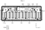
FIG. 4 is a view showing a state in which the front end plate and the front sealing plate are removed in the battery module shown inFIG. 1 . -
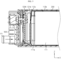
FIGS. 5 and6 are views showing the flow of the insulating cooling liquid for cooling. -
FIGS. 7 and8 are views showing a coupling relationship between a cooling fin and a battery cell according to the present disclosure. -
FIG. 9 is a perspective view showing a cooling fin according to the present disclosure. -
FIG. 10 is a diagram showing a coupling structure of a bus bar frame assembly and a cooling fin according to the present disclosure. -
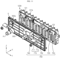
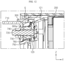
FIGS. 11 and12 are views showing a specific structure of a terminal assembly according to the present disclosure. -
FIG. 13 is a diagram showing an arrangement structure of a sensing assembly according to the present disclosure. - Hereinafter, preferred embodiments of the present disclosure will be described in detail with reference to the accompanying drawings. Prior to the description, it should be understood that the terms used in the specification and the appended claims should not be construed as limited to general and dictionary meanings, but interpreted based on the meanings and concepts corresponding to technical aspects of the present disclosure on the basis of the principle that the inventor is allowed to define terms appropriately for the best explanation. Therefore, the description proposed herein is just a preferable example for the purpose of illustrations only, not intended to limit the scope of the disclosure, so it should be understood that other equivalents and modifications could be made thereto without departing from the scope of the disclosure.
- Referring to
FIGS. 1 ,2 and4 , the battery module according to an embodiment of the present disclosure includes asub module 100, amodule housing 200, afront sealing plate 300, arear sealing plate 400 and asensing assembly 800. The battery module may further include afront end plate 500 and/or arear end plate 600 and/or a pair ofterminal assemblies 700 in addition to the above-described components. - Referring to
FIGS.2 to 9 , thesub module 100 includes a cell stack assembly 110. Thesub module 100 includes a front busbar frame assembly 120A and a rear busbar frame assembly 120B in addition to the cell stack assembly 110. - The cell stack assembly 110 includes a plurality of
battery cells 111. In addition, the cell stack assembly 110 may further include at least onecooling fin 112 interposed betweenadjacent battery cells 111 and/or at least onebuffer pad 113 interposed between theadjacent battery cells 111. The plurality ofbattery cells 111 are stacked approximately in a vertical standing form on the ground (a side parallel to the X-Y plane) to form a single cell stack assembly 110. When the cell stack assembly 110 includes thecooling fin 112 and/or thebuffer pad 113, thecooling fin 112 and/or thebuffer pad 113 are also stacked in a vertical standing form approximately perpendicular to the ground (surface parallel to the X-Y plane) together with the plurality ofbattery cells 111 to form a single cell stack assembly 110. - As the
battery cell 111, a pouch-type battery cell having a pair of electrode leads 111a drawn out in opposite directions along the longitudinal direction (parallel to the X-axis) may be used. - Referring to
FIGS. 7 to 9 , thecooling fin 112 includes abody contact portion 112a interposed between thebattery cells 111 adjacent to each other, and awing cover portion 112b bent at any one of the top and bottom of thebody contact portion 112a to cover the cell wing portion W of thebattery cell 111. Thecooling fin 112 may further include a pair offixing portions 112c formed at both ends in the longitudinal direction (parallel to the X-axis) of thewing cover portion 112b. - As shown in
FIG. 7 , when thebattery cell 111 is of a pouch type, an area in which an electrode assembly (not shown) is accommodated may be defined as the cell body portion B, and a region elongated along the longitudinal direction (parallel to the X-axis) of the battery module in the sealing area formed around the cell body portion B may be defined as the cell wing portion W. - The
body contact portion 112a is interposed between the cell body portions B of the pair ofadjacent battery cells 111 and is in direct contact with the cell body portions B of thebattery cells 111. Thebody contact portion 112a rapidly conducts heat generated from the cell body portion B of thebattery cell 111 in the width direction of thecooling fin 112, that is, in the height direction (parallel to the Z-axis) of the battery module to move toward thewing cover portion 112b. As such, the heat conducted toward thewing cover portion 112b is transferred along the longitudinal direction (parallel to the X-axis) of the battery module by the insulating cooling liquid flowing through the cooling liquid flow path P formed between the cell wing portion W of thebattery cell 111 and thewing cover portion 112b of thecooling fin 112 and is discharged to the outside of the battery module. - In addition to forming the cooling liquid flow path P as described above, the
wing cover portion 112b may also perform the function of absorbing the impact when external impact is applied so that the cell stack assembly 110 moves in the vertical direction (parallel to the Z-axis) within themodule housing 200. This impact absorption function of thewing cover portion 112b may help prevent damage to thesensing line 810 and thetemperature sensor 820 interposed between the cell wing portion W and the cell body portion B (seeFIG. 13 ). Thesensing assembly 800 including thesensing line 810 and thetemperature sensor 820 will be described later in detail. - The
fixing portion 112c has a shape corresponding to aguide rib 121b to be described later. As thefixing portion 112c is coupled to theguide rib 121b, thefixing portion 112c guides the fastening between the cell stack assembly 110 including thecooling fin 112 and the busbar frame assemblies - The
buffer pad 113 may be interposed betweenadjacent battery cells 111 to absorb volume expansion due to swelling of thebattery cells 111. - The front bus
bar frame assembly 120A and the rear busbar frame assembly 120B are coupled to one side and the other side in the longitudinal direction (parallel to the X axis) of the cell stack assembly 110, respectively, so that a plurality ofbattery cells 111 are electrically connected. The front busbar frame assembly 120A and the rear busbar frame assembly 120B have substantially the same structure except that the front busbar frame assembly 120A is provided with theinner terminal 123 and the rear busbar frame assembly 120B is not provided with theinner terminal 123. Accordingly, a detailed description of the specific structure of the rear busbar frame assembly 120B will be omitted, and a detailed description of the specific structure of the front busbar frame assembly 120A will be intensively described. - Referring to
FIGS. 4 to 10 , the front busbar frame assembly 120A includes abus bar frame 121 and a plurality of bus bars 122. In addition, the front busbar frame assembly 120A may further include a pair ofinner terminals 123. Thebus bar frame 121 covers one side of the cell stack assembly 110 in the longitudinal direction (parallel to the X-axis). - The
bus bar frame 121 has a plurality of coolingliquid holes 121a. The coolingliquid hole 121a functions as a passage so that the insulating cooling liquid introduced into themodule housing 200 through the inlet P1 provided in thefront sealing plate 300 may flow toward the cell stack assembly 110 through thebus bar frame 121. - As shown in
FIGS. 7 and8 , the cooling liquid flow path P is formed between themodule housing 200 and the cell wing portion W. When the cell stack assembly 110 of the present disclosure includes the coolingfin 112, the cooling liquid flow path P may be formed between thewing cover portion 112b and the cell wing portion W in addition to between themodule housing 200 and the cell wing portion W. Accordingly, for smooth supply and discharge of the insulating cooling liquid, the coolingliquid hole 121a may be formed between themodule housing 200 and the cell wing portion W. Also, the coolingliquid hole 121a may be formed at a position corresponding to the cooling liquid flow path P formed between thewing cover portion 112b and the cell wing portion W. - The insulating cooling liquid introduced toward the cell stack assembly 110 through the cooling
liquid hole 121a formed in the front busbar frame assembly 120A is flowed toward the rear busbar frame assembly 120B through the cooling liquid flow path P along the arrow (seeFIGS. 5 and6 ). The insulating cooling liquid that has moved to the rearbus bar frame 120B flows toward therear sealing plate 400 through the coolingliquid hole 121a formed in the rearbus bar frame 120B, and is emitted out of the battery module through an outlet P2 provided in therear sealing plate 400. In this process, the insulating cooling liquid comes into direct contact with theelectrode lead 111a of thebattery cell 111 and the cell wing portion W to cool thebattery cell 111. - The
bus bar 122 is fixed on thebus bar frame 121 and is coupled to theelectrode lead 111a drawn out through a lead slit formed in thebus bar frame 121 to electrically connect the plurality ofbattery cells 111. - The
inner terminal 123 is fixed on thebus bar frame 121 and is coupled to theelectrode lead 111a of thebattery cell 111 located at theoutermost battery cell 111 among thebattery cells 111 provided in the cell stack assembly 110. Theinner terminal 123 functions as a high potential terminal. Theinner terminal 123 located at one side of the longitudinal direction (parallel to the Y-axis) of thebus bar frame 121 functions as a positive electrode high potential terminal, and theinner terminal 123 located at the other longitudinal side of thebus bar frame 121 functions as a negative electrode high potential terminal. Theinner terminal 123 is electrically connected to an outer terminal 710 (seeFIGS. 11 and12 ) to be described later. - Meanwhile, referring to
FIGS. 5 to 10 , thebus bar frame 121 of the front busbar frame assembly 120A and thebus bar frame 121 of the rear busbar frame assembly 120B include a plurality ofguide ribs 121b formed on the top and bottom along the longitudinal direction (parallel to the Y-axis). Theguide rib 121b has a shape extending in the direction toward the cell stack assembly 110. Theguide rib 121b is formed at a position corresponding to the fixingportion 112c of the coolingfin 112. - As described above, the fixing
portion 112c having a shape corresponding to theguide rib 121b is formed at both ends of thewing cover portion 112b of the coolingfin 112 in the longitudinal direction (parallel to the X-axis). By theguide rib 121b and the fixingportion 112c, the movement of the coolingfin 112 in the vertical direction (parallel to the Z-axis) and longitudinal direction (parallel to the X-axis) is restricted. Accordingly, when the front busbar frame assembly 120A and the rear busbar frame assembly 120B are coupled to the cell stack assembly 110, the coupling position may be guided, thereby increasing the convenience of assembly. - Referring to
FIGS. 1 to 6 , themodule housing 200 accommodates asub module 100 including the cell stack assembly 110, the front busbar frame assembly 120A, and the rear busbar frame assembly 120B. Themodule housing 200 has one side and the other side open in the longitudinal direction (parallel to the X-axis). - Referring to
FIGS. 5 ,6 ,11 and12 , thefront sealing plate 300 covers the opening formed at one side of themodule housing 200 in the longitudinal direction (parallel to the X-axis). Thefront sealing plate 300 has a cooling liquid inlet P1 for inflow of the insulating cooling liquid. To prevent the insulating cooling liquid from leaking, a gasket G may be interposed between the edge surface of thefront sealing plate 300 and the inner surface of the module housing 200 (seeFIG. 12 ). - The
front sealing plate 300 is provided with a pair ofterminal holes 300a through which components for electrical connection between theinner terminal 123 provided in the front busbar frame assembly 120A and theouter terminal 710 to be described later may pass. Theterminal hole 300a is formed at a position corresponding to theinner terminal 123. - Referring to
FIG. 6 , therear sealing plate 400 covers the opening at the other side in the longitudinal direction (parallel to the X-axis) of themodule housing 200, and has a cooling liquid outlet P2 for discharging the insulating cooling liquid. As in the case of thefront sealing plate 300, a gasket G may be interposed between the edge surface of thereal sealing plate 400 and the inner surface of themodule housing 200 to prevent the insulating cooling liquid from leaking. - The
front sealing plate 300 andrear sealing plate 400 may be made of an insulating resin for electrical insulation. - Referring to
FIGS. 11 and12 , theterminal assembly 700 includes anouter terminal 710 positioned on the outside of thefront sealing plate 300 and astud 720 electrically connecting theouter terminal 710 and thebattery cell 111. Thestud 720 is fixed to theinner terminal 123. Thestud 720 may penetrate theinner terminal 123 and be fixed to theinner terminal 123 by press-fitting. Thestud 720 fixed to theinner terminal 123 is drawn out through theterminal hole 300a formed in thefront sealing plate 300 and coupled with theouter terminal 710. - The
terminal assembly 700 may further include a ring-shapedterminal spacer 730 inserted into theterminal hole 300a formed in thefront sealing plate 300. Theterminal spacer 730 may be made of a metal material. If theterminal spacer 730 is provided, thestud 720 passes through theterminal spacer 730. - The
terminal assembly 700 may further include afastening nut 740 for fastening theouter terminal 710 to thestud 720. Thefastening nut 740 is fastened to thestud 720 penetrating theterminal spacer 730 and thefastening portion 712 of theouter terminal 710 so that thefastening portion 712 of theouter terminal 710 is tightly fixed to theterminal spacer 730. Accordingly, theinner terminal 123 and theouter terminal 710 are electrically connected to each other through theterminal spacer 730. - The
terminal assembly 700 may further include a first O-ring 750 that covers the outer circumference of theterminal spacer 730 and is interposed between the inner surface of thefront sealing plate 300 and theinner terminal 123. Referring toFIGS. 11 and12 , the first O-ring 750 prevents the insulating cooling liquid introduced into the space between thefront sealing plate 300 and thebus bar frame 121 from leaking to the outside of thefront sealing plate 300 through the space between the inner surface of theterminal hole 300a and theterminal spacer 730. - In addition, the
terminal assembly 700 may further include a second O-ring 760 that is positioned around thestud 720 press-fitted into theinner terminal 123 and exposed to the space between theinner terminal 123 and thebus bar frame 121, and is interposed between theinner terminal 123 and thebus bar frame 121. The second O-ring 760 prevents the insulating cooling liquid introduced into the space between thefront sealing plate 300 and thebus bar frame 121 from leaking to the outside of thefront sealing plate 300 through the space between theinner terminal 123 and thestud 720 and the space between the inner surface of theterminal spacer 730 and thestud 720. - Referring to
FIGS. 1 and2 andFIGS. 5 and6 , thefront end plate 500 covers thefront sealing plate 300 and is fixed to themodule housing 200. Therear end plate 600 covers therear sealing plate 400 and is fixed to themodule housing 200. - The
front end plate 500 includes aterminal exposing portion 500a for exposing theconnection portion 711 of theouter terminal 710 to the outside of thefront end plate 500, and aninlet exposing portion 500b for exposing the inlet P1 to the outside of thefront end plate 500. Therear end plate 600 includes an outlet exposing portion 600b for exposing the cooling liquid outlet P2 to the outside of therear end plate 600. - When the
front end plate 500 and therear end plate 600 are applied to the battery module according to the present disclosure, a gasket for preventing the insulating cooling liquid from leaking may be applied to the coupling area between thefront end plate 500 and themodule housing 200 and the coupling area between therear end plate 600 and themodule housing 200. - Referring to
FIGS. 4 ,7 , and13 , thesensing assembly 800 is disposed on the top of thesub module 100 and senses the voltage of thebattery cell 111. Thesensing assembly 800 includes asensing line 810 electrically connected to the plurality ofbattery cells 111 and extending from one end of thebattery cell 111 in the longitudinal direction (parallel to the X-axis) to the other longitudinal end. Thesensing line 810 is electrically connected to thebattery cells 111 at one side and the other side of the cell stack assembly 110 in the longitudinal direction (parallel to the X-axis). The electrical connection between thesensing line 810 and thebattery cell 111 may be realized by coupling thesensing line 810 to thebus bar 122. However, the present disclosure is not limited thereto, and it is also possible that thesensing line 810 is directly coupled to theelectrode lead 111a of thebattery cell 111. - The
sensing line 810 may be interposed between the cell body portion B of the pouch-type battery cell 111 and the cell wing portion W folded toward the cell body portion B. This is to prevent thesensing line 810 from being damaged by the insulating cooling liquid flowing inside the battery module. - The
sensing assembly 800 may additionally perform the function of sensing the temperature of thebattery cell 111 in addition to sensing the voltage. To this end, thesensing assembly 800 may further include at least onetemperature sensor 820 mounted on thesensing line 810. Thetemperature sensor 820 may be disposed adjacent to theelectrode lead 111a having a large heat generation. Like thesensing line 810, thetemperature sensor 820 may be interposed between the cell body portion B of thebattery cell 111 and the cell wing portion W folded toward the cell body portion B. This is to prevent thetemperature sensor 820 from being damaged by the insulating cooling liquid flowing inside the battery module. In addition, this is to prevent or minimize the contact between thetemperature sensor 820 and the insulating cooling liquid so that the temperature of thebattery cell 111 can be accurately sensed. Meanwhile, thesensing line 810 and thetemperature sensor 820 may be additionally covered by thewing cover portion 112b of the coolingfin 112 in a state of being covered by the cell wing portion W. - The
sensing assembly 800 may further include a printed circuit board (PCB) 830 electrically connected to thesensing line 810 in addition to thesensing line 810. ThePCB 830 may be fixed on thebus bar frame 121. A connector assembly (not shown) may be mounted on thePCB 830, and a control device such as a battery management system (BMS) (not shown) may be connected through this connector assembly. In this case, the BMS may measure and/or receive information about the voltage, temperature, etc. of thebattery cell 111 and control charging/discharging of the battery module with reference to this. - A battery pack according to an embodiment of the present disclosure may include the battery module according to an embodiment of the present disclosure as described above. The battery pack may include additional components such as a pack housing and/or a battery management system (BMS) together with at least one battery module. The battery module may be fastened to the pack housing through the fastening hole H formed in the
front end plate 500 and/or therear end plate 600. That is, the fastening hole H may provide a space into which a fastening means such as a bolt for fastening the pack housing and the battery module is inserted. Meanwhile, when the battery pack includes a plurality of battery modules, it is also possible that the plurality of battery modules are fastened to each other through the fastening hole H formed in thefront end plate 500 and/or therear end plate 600. - The vehicle according to an embodiment of the present disclosure may include at least one battery module and/or the battery pack as described above. The vehicle according to an embodiment of the present disclosure may be, for example, a hybrid vehicle or an electric vehicle that operates by being powered by the battery module and/or the battery pack of the present disclosure.
- The present disclosure has been described in detail. However, it should be understood that the detailed description and specific examples, while indicating preferred embodiments of the disclosure, are given by way of illustration only, since various changes and modifications within the scope of the disclosure will become apparent to those skilled in the art from this detailed description.
-
- 100:
- sub module
- 110:
- cell stack assembly
- 111:
- battery cell
- 111a:
- electrode lead
- 112:
- cooling fin
- 112a:
- body contact portion
- 112b:
- wing cover portion
- 112c:
- fixing portion
- 113:
- buffer pad
- P:
- cooling liquid flow path
- 120A:
- front bus bar frame assembly
- 120B:
- rear bus bar frame assembly
- 121:
- bus bar frame
- 121a:
- cooling liquid hole
- 121b:
- guide rib
- 122:
- bus bar
- 123:
- inner terminal
- 200:
- module housing
- 300:
- front sealing plate
- 300a:
- terminal hole
- P1:
- inlet (inlet)
- G:
- gasket
- 400:
- rear sealing plate
- P2:
- outlet
- 500:
- front end plate
- 500a:
- terminal exposing portion
- 500b:
- inlet exposing portion
- 600:
- rear end plate
- 600b:
- outlet exposing portion
- 700:
- terminal assembly
- 710:
- outer terminal
- 711:
- connection portion
- 712:
- fastening portion
- 720:
- stud
- 730:
- terminal spacer
- 740:
- fastening nut
- 750:
- first O-ring
- 760:
- second O-ring
- 800:
- sensing assembly
- 810:
- sensing line
- 820:
- temperature sensor
- 830:
- PCB (Printed Circuit Board)
Claims (13)
- A battery module, comprising:a sub module including a cell stack assembly having a plurality of battery cells and a cooling fin interposed between adjacent battery cells;a module housing configured to accommodate the sub module;a front sealing plate configured to cover an opening at one longitudinal side of the module housing and having an inlet;a rear sealing plate configured to cover an opening at the other longitudinal side of the module housing and having an outlet; anda sensing assembly configured to sense voltage of the battery cell.
- The battery module according to claim 1, wherein the sensing assembly is disposed on a top of the sub module.
- The battery module according to claim 1, wherein the sensing assembly includes a sensing line electrically connected to the plurality of battery cells and extending from one longitudinal end of the battery cells to the other longitudinal end.
- The battery module according to claim 3, wherein the sensing line is interposed between a cell body portion of the battery cell and a cell wing portion folded toward the cell body portion.
- The battery module according to claim 3, wherein the sensing assembly further includes a temperature sensor mounted on the sensing line.
- The battery module according to claim 5, wherein the temperature sensor is interposed between a cell body portion of the battery cell and a cell wing portion folded toward the cell body portion.
- The battery module according to claim 1, wherein the cooling fin includes:a body contact portion interposed between adjacent battery cells, anda wing cover portion bent at any one of a top and bottom of the body contact portion to cover a cell wing portion of the battery cell.
- The battery module according to claim 7, wherein the sub module further includes:a front bus bar frame assembly coupled to one longitudinal side of the cell stack assembly; anda rear bus bar frame assembly coupled to the other longitudinal side of the cell stack assembly.
- The battery module according to claim 8, wherein the front bus bar frame assembly and the rear bus bar frame assembly have a plurality of cooling liquid holes formed at a position corresponding to a cooling liquid flow path formed between the module housing and the cell wing portion of the battery cell and between the wing cover portion and the cell wing portion of the battery cell.
- The battery module according to claim 9, wherein an insulating cooling liquid introduced into the module housing through the inlet passes through the cooling liquid hole formed in the front bus bar frame assembly and flows to the cooling liquid flow path.
- The battery module according to claim 10, wherein the insulating cooling liquid passing through the cooling liquid flow path passes through the cooling liquid hole formed in the rear bus bar frame assembly and is discharged to the outside of the module housing through the outlet.
- A battery pack comprising the battery module according to any one of claims 1 to 11.
- A vehicle comprising the battery module according to any one of claims 1 to 11.
Applications Claiming Priority (2)
| Application Number | Priority Date | Filing Date | Title |
|---|---|---|---|
| KR1020210074425A KR102934587B1 (en) | 2021-06-08 | 2021-06-08 | Battery module having a cooling structure using insulating oil, and a battery pack and vehicle comprising the same |
| PCT/KR2022/008029 WO2022260409A1 (en) | 2021-06-08 | 2022-06-07 | Battery module, and battery pack and vehicle comprising same |
Publications (2)
| Publication Number | Publication Date |
|---|---|
| EP4216342A1 true EP4216342A1 (en) | 2023-07-26 |
| EP4216342A4 EP4216342A4 (en) | 2024-05-01 |
Family
ID=84425321
Family Applications (1)
| Application Number | Title | Priority Date | Filing Date |
|---|---|---|---|
| EP22820537.3A Pending EP4216342A4 (en) | 2021-06-08 | 2022-06-07 | Battery module, and battery pack and vehicle comprising same |
Country Status (6)
| Country | Link |
|---|---|
| US (1) | US20230402681A1 (en) |
| EP (1) | EP4216342A4 (en) |
| JP (1) | JP7561976B2 (en) |
| KR (1) | KR102934587B1 (en) |
| CN (1) | CN116368663A (en) |
| WO (1) | WO2022260409A1 (en) |
Families Citing this family (5)
| Publication number | Priority date | Publication date | Assignee | Title |
|---|---|---|---|---|
| KR20240130464A (en) * | 2023-02-22 | 2024-08-29 | 에스케이온 주식회사 | Battery case and Battery pack including the same |
| JP2026502918A (en) * | 2023-11-17 | 2026-01-27 | エルジー エナジー ソリューション リミテッド | Battery assembly and device including same |
| JP2026512781A (en) * | 2024-02-20 | 2026-04-21 | エルジー エナジー ソリューション リミテッド | Battery cell assembly and battery pack containing the same |
| KR102913984B1 (en) * | 2024-02-20 | 2026-01-16 | 주식회사 엘지에너지솔루션 | Battery assembly and battery pack including the same |
| CN118448774B (en) * | 2024-07-08 | 2024-09-24 | 宁波共盛能源科技有限公司 | Heat dissipation temperature control system of lithium battery energy storage cabinet |
Family Cites Families (13)
| Publication number | Priority date | Publication date | Assignee | Title |
|---|---|---|---|---|
| KR101029838B1 (en) * | 2007-06-28 | 2011-04-15 | 주식회사 엘지화학 | Medium and large battery packs with improved cooling efficiency |
| JP5142605B2 (en) * | 2007-06-28 | 2013-02-13 | 三洋電機株式会社 | Power supply for vehicle |
| JP2012204129A (en) * | 2011-03-25 | 2012-10-22 | Hitachi Maxell Ltd | Battery pack |
| US9786961B2 (en) * | 2011-07-25 | 2017-10-10 | Lightening Energy | Rapid charging electric vehicle and method and apparatus for rapid charging |
| CN104795606B (en) * | 2014-01-21 | 2017-04-26 | 微宏动力系统(湖州)有限公司 | liquid-cooled battery pack system |
| KR101821376B1 (en) * | 2014-04-03 | 2018-01-23 | 주식회사 엘지화학 | Battery module array having 2-cell with center frame type module |
| KR101943542B1 (en) * | 2015-09-21 | 2019-01-29 | 주식회사 엘지화학 | Battery module and battery pack comprising the same |
| DE102016201199A1 (en) * | 2016-01-27 | 2017-07-27 | Robert Bosch Gmbh | Method for isolating a battery module |
| JP7031260B2 (en) * | 2017-12-01 | 2022-03-08 | 株式会社オートネットワーク技術研究所 | Power storage module |
| KR102364283B1 (en) * | 2017-12-01 | 2022-02-16 | 주식회사 엘지에너지솔루션 | Battery Module Having Heat Dissipation Plate |
| PL3493292T3 (en) * | 2017-12-04 | 2023-07-31 | Samsung Sdi Co., Ltd. | Battery system including removable battery component carriers and vehicle including the battery system |
| KR102522165B1 (en) * | 2018-12-26 | 2023-04-13 | 주식회사 엘지에너지솔루션 | A battery module having a structure capable of accurate temperature sensing, a battery pack and a vehicle comprising the same |
| KR20210074425A (en) | 2019-12-11 | 2021-06-22 | 삼성전자주식회사 | Stroage controller for correcting error, storage device having the same, and operating method thereof |
-
2021
- 2021-06-08 KR KR1020210074425A patent/KR102934587B1/en active Active
-
2022
- 2022-06-07 EP EP22820537.3A patent/EP4216342A4/en active Pending
- 2022-06-07 WO PCT/KR2022/008029 patent/WO2022260409A1/en not_active Ceased
- 2022-06-07 JP JP2023517792A patent/JP7561976B2/en active Active
- 2022-06-07 CN CN202280006873.6A patent/CN116368663A/en active Pending
- 2022-06-07 US US18/034,950 patent/US20230402681A1/en active Pending
Also Published As
| Publication number | Publication date |
|---|---|
| KR102934587B1 (en) | 2026-03-04 |
| JP7561976B2 (en) | 2024-10-04 |
| EP4216342A4 (en) | 2024-05-01 |
| KR20220165592A (en) | 2022-12-15 |
| JP2023541965A (en) | 2023-10-04 |
| CN116368663A (en) | 2023-06-30 |
| US20230402681A1 (en) | 2023-12-14 |
| WO2022260409A1 (en) | 2022-12-15 |
Similar Documents
| Publication | Publication Date | Title |
|---|---|---|
| EP4270605A1 (en) | Battery module, and battery pack and vehicle comprising same | |
| EP4216342A1 (en) | Battery module, and battery pack and vehicle comprising same | |
| EP4199194A1 (en) | Battery module, and battery pack and vehicle including same | |
| KR102753461B1 (en) | A battery module with efficient assembly structure, a battery pack and a vehicle comprising the same | |
| EP4203146B1 (en) | Battery module having cooling structure using insulating oil, and battery pack and vehicle comprising same | |
| EP4191752B1 (en) | Battery module having cooling structure using insulation coolant, and battery pack and vehicle which include same | |
| KR101127603B1 (en) | Bus bar holder and battery pack comprising the same | |
| CN103283057B (en) | Busbar module, vehicle power source device and vehicle | |
| EP4216343B1 (en) | Battery module, and battery pack and vehicle including the same | |
| US20200243817A1 (en) | Battery Module, Battery Pack Comprising the Battery Module and Vehicle Comprising the Battery Pack | |
| KR20200040619A (en) | Battery Module with ICB assembly in a space-saving sturcture | |
| KR20220021364A (en) | Battery module having a cooling structure using insulating oil, and a battery pack and vehicle comprising the same | |
| US20240421377A1 (en) | Battery module and battery case | |
| EP3641015A1 (en) | Power storage device | |
| CN118281389A (en) | Rechargeable battery pack | |
| EP4485618A1 (en) | Flexible printed circuit board and secondary battery module comprising same | |
| US20250132520A1 (en) | Waterproof connector and battery module including the same | |
| CN118633196A (en) | Battery Module |
Legal Events
| Date | Code | Title | Description |
|---|---|---|---|
| STAA | Information on the status of an ep patent application or granted ep patent |
Free format text: STATUS: THE INTERNATIONAL PUBLICATION HAS BEEN MADE |
|
| PUAI | Public reference made under article 153(3) epc to a published international application that has entered the european phase |
Free format text: ORIGINAL CODE: 0009012 |
|
| STAA | Information on the status of an ep patent application or granted ep patent |
Free format text: STATUS: REQUEST FOR EXAMINATION WAS MADE |
|
| 17P | Request for examination filed |
Effective date: 20230421 |
|
| AK | Designated contracting states |
Kind code of ref document: A1 Designated state(s): AL AT BE BG CH CY CZ DE DK EE ES FI FR GB GR HR HU IE IS IT LI LT LU LV MC MK MT NL NO PL PT RO RS SE SI SK SM TR |
|
| A4 | Supplementary search report drawn up and despatched |
Effective date: 20240403 |
|
| RIC1 | Information provided on ipc code assigned before grant |
Ipc: H01M 10/647 20140101ALI20240326BHEP Ipc: H01M 50/249 20210101ALI20240326BHEP Ipc: H01M 50/211 20210101ALI20240326BHEP Ipc: H01M 50/502 20210101ALI20240326BHEP Ipc: H01M 10/48 20060101ALI20240326BHEP Ipc: H01M 10/613 20140101ALI20240326BHEP Ipc: H01M 10/625 20140101ALI20240326BHEP Ipc: H01M 10/6567 20140101ALI20240326BHEP Ipc: H01M 10/6551 20140101AFI20240326BHEP |
|
| DAV | Request for validation of the european patent (deleted) | ||
| DAX | Request for extension of the european patent (deleted) | ||
| STAA | Information on the status of an ep patent application or granted ep patent |
Free format text: STATUS: EXAMINATION IS IN PROGRESS |
|
| 17Q | First examination report despatched |
Effective date: 20250508 |