EP4216334A1 - Battery cell, battery module, battery pack, battery management system and method for determining a value of at least one wear parameter of a battery cell - Google Patents
Battery cell, battery module, battery pack, battery management system and method for determining a value of at least one wear parameter of a battery cell Download PDFInfo
- Publication number
- EP4216334A1 EP4216334A1 EP22152407.7A EP22152407A EP4216334A1 EP 4216334 A1 EP4216334 A1 EP 4216334A1 EP 22152407 A EP22152407 A EP 22152407A EP 4216334 A1 EP4216334 A1 EP 4216334A1
- Authority
- EP
- European Patent Office
- Prior art keywords
- battery
- wear
- cell
- module
- sensor
- Prior art date
- Legal status (The legal status is an assumption and is not a legal conclusion. Google has not performed a legal analysis and makes no representation as to the accuracy of the status listed.)
- Pending
Links
- 238000000034 method Methods 0.000 title claims description 14
- 210000004027 cell Anatomy 0.000 claims abstract description 205
- 210000005056 cell body Anatomy 0.000 claims abstract description 50
- 230000000007 visual effect Effects 0.000 claims abstract description 32
- 230000003287 optical effect Effects 0.000 claims description 20
- 239000000463 material Substances 0.000 claims description 12
- OIFBSDVPJOWBCH-UHFFFAOYSA-N Diethyl carbonate Chemical compound CCOC(=O)OCC OIFBSDVPJOWBCH-UHFFFAOYSA-N 0.000 claims description 6
- KMTRUDSVKNLOMY-UHFFFAOYSA-N Ethylene carbonate Chemical compound O=C1OCCO1 KMTRUDSVKNLOMY-UHFFFAOYSA-N 0.000 claims description 6
- 239000011248 coating agent Substances 0.000 claims description 3
- 238000000576 coating method Methods 0.000 claims description 3
- 238000010422 painting Methods 0.000 claims description 3
- 230000008901 benefit Effects 0.000 description 13
- 230000000694 effects Effects 0.000 description 12
- 238000011835 investigation Methods 0.000 description 8
- 239000007789 gas Substances 0.000 description 7
- 239000003792 electrolyte Substances 0.000 description 6
- 238000012549 training Methods 0.000 description 6
- KRHYYFGTRYWZRS-UHFFFAOYSA-N Fluorane Chemical compound F KRHYYFGTRYWZRS-UHFFFAOYSA-N 0.000 description 5
- 150000003839 salts Chemical class 0.000 description 5
- 238000012360 testing method Methods 0.000 description 5
- 239000012780 transparent material Substances 0.000 description 5
- 238000013459 approach Methods 0.000 description 4
- 229910000040 hydrogen fluoride Inorganic materials 0.000 description 4
- 229910001290 LiPF6 Inorganic materials 0.000 description 3
- 230000032683 aging Effects 0.000 description 3
- 238000003491 array Methods 0.000 description 3
- 238000004590 computer program Methods 0.000 description 3
- 230000002159 abnormal effect Effects 0.000 description 2
- 238000013528 artificial neural network Methods 0.000 description 2
- 230000008859 change Effects 0.000 description 2
- 238000006243 chemical reaction Methods 0.000 description 2
- 230000001419 dependent effect Effects 0.000 description 2
- 238000001514 detection method Methods 0.000 description 2
- 238000002405 diagnostic procedure Methods 0.000 description 2
- 238000010586 diagram Methods 0.000 description 2
- 238000000157 electrochemical-induced impedance spectroscopy Methods 0.000 description 2
- 238000004146 energy storage Methods 0.000 description 2
- 238000007654 immersion Methods 0.000 description 2
- 229910001416 lithium ion Inorganic materials 0.000 description 2
- 229910003002 lithium salt Inorganic materials 0.000 description 2
- 159000000002 lithium salts Chemical class 0.000 description 2
- 230000008018 melting Effects 0.000 description 2
- 238000002844 melting Methods 0.000 description 2
- 239000003960 organic solvent Substances 0.000 description 2
- 238000013021 overheating Methods 0.000 description 2
- 230000008961 swelling Effects 0.000 description 2
- 231100000331 toxic Toxicity 0.000 description 2
- 230000002588 toxic effect Effects 0.000 description 2
- 230000008016 vaporization Effects 0.000 description 2
- 238000009834 vaporization Methods 0.000 description 2
- 239000002390 adhesive tape Substances 0.000 description 1
- 230000009172 bursting Effects 0.000 description 1
- 230000032677 cell aging Effects 0.000 description 1
- 230000001066 destructive effect Effects 0.000 description 1
- 238000005562 fading Methods 0.000 description 1
- 230000006870 function Effects 0.000 description 1
- 230000036541 health Effects 0.000 description 1
- 238000007689 inspection Methods 0.000 description 1
- 230000002427 irreversible effect Effects 0.000 description 1
- 239000013307 optical fiber Substances 0.000 description 1
- 230000008569 process Effects 0.000 description 1
- 238000004064 recycling Methods 0.000 description 1
- 229910001415 sodium ion Inorganic materials 0.000 description 1
- 238000011179 visual inspection Methods 0.000 description 1
- XLYOFNOQVPJJNP-UHFFFAOYSA-N water Chemical compound O XLYOFNOQVPJJNP-UHFFFAOYSA-N 0.000 description 1
Images


Classifications
-
- H—ELECTRICITY
- H01—ELECTRIC ELEMENTS
- H01M—PROCESSES OR MEANS, e.g. BATTERIES, FOR THE DIRECT CONVERSION OF CHEMICAL ENERGY INTO ELECTRICAL ENERGY
- H01M10/00—Secondary cells; Manufacture thereof
- H01M10/42—Methods or arrangements for servicing or maintenance of secondary cells or secondary half-cells
- H01M10/425—Structural combination with electronic components, e.g. electronic circuits integrated to the outside of the casing
-
- H—ELECTRICITY
- H01—ELECTRIC ELEMENTS
- H01M—PROCESSES OR MEANS, e.g. BATTERIES, FOR THE DIRECT CONVERSION OF CHEMICAL ENERGY INTO ELECTRICAL ENERGY
- H01M10/00—Secondary cells; Manufacture thereof
- H01M10/42—Methods or arrangements for servicing or maintenance of secondary cells or secondary half-cells
- H01M10/48—Accumulators combined with arrangements for measuring, testing or indicating the condition of cells, e.g. the level or density of the electrolyte
- H01M10/482—Accumulators combined with arrangements for measuring, testing or indicating the condition of cells, e.g. the level or density of the electrolyte for several batteries or cells simultaneously or sequentially
-
- H—ELECTRICITY
- H01—ELECTRIC ELEMENTS
- H01M—PROCESSES OR MEANS, e.g. BATTERIES, FOR THE DIRECT CONVERSION OF CHEMICAL ENERGY INTO ELECTRICAL ENERGY
- H01M10/00—Secondary cells; Manufacture thereof
- H01M10/42—Methods or arrangements for servicing or maintenance of secondary cells or secondary half-cells
- H01M10/48—Accumulators combined with arrangements for measuring, testing or indicating the condition of cells, e.g. the level or density of the electrolyte
- H01M10/488—Cells or batteries combined with indicating means for external visualization of the condition, e.g. by change of colour or of light density
-
- H—ELECTRICITY
- H01—ELECTRIC ELEMENTS
- H01M—PROCESSES OR MEANS, e.g. BATTERIES, FOR THE DIRECT CONVERSION OF CHEMICAL ENERGY INTO ELECTRICAL ENERGY
- H01M50/00—Constructional details or processes of manufacture of the non-active parts of electrochemical cells other than fuel cells, e.g. hybrid cells
- H01M50/50—Current conducting connections for cells or batteries
- H01M50/569—Constructional details of current conducting connections for detecting conditions inside cells or batteries, e.g. details of voltage sensing terminals
-
- H—ELECTRICITY
- H01—ELECTRIC ELEMENTS
- H01M—PROCESSES OR MEANS, e.g. BATTERIES, FOR THE DIRECT CONVERSION OF CHEMICAL ENERGY INTO ELECTRICAL ENERGY
- H01M10/00—Secondary cells; Manufacture thereof
- H01M10/42—Methods or arrangements for servicing or maintenance of secondary cells or secondary half-cells
- H01M10/425—Structural combination with electronic components, e.g. electronic circuits integrated to the outside of the casing
- H01M2010/4271—Battery management systems including electronic circuits, e.g. control of current or voltage to keep battery in healthy state, cell balancing
-
- H—ELECTRICITY
- H01—ELECTRIC ELEMENTS
- H01M—PROCESSES OR MEANS, e.g. BATTERIES, FOR THE DIRECT CONVERSION OF CHEMICAL ENERGY INTO ELECTRICAL ENERGY
- H01M10/00—Secondary cells; Manufacture thereof
- H01M10/42—Methods or arrangements for servicing or maintenance of secondary cells or secondary half-cells
- H01M10/425—Structural combination with electronic components, e.g. electronic circuits integrated to the outside of the casing
- H01M2010/4278—Systems for data transfer from batteries, e.g. transfer of battery parameters to a controller, data transferred between battery controller and main controller
-
- Y—GENERAL TAGGING OF NEW TECHNOLOGICAL DEVELOPMENTS; GENERAL TAGGING OF CROSS-SECTIONAL TECHNOLOGIES SPANNING OVER SEVERAL SECTIONS OF THE IPC; TECHNICAL SUBJECTS COVERED BY FORMER USPC CROSS-REFERENCE ART COLLECTIONS [XRACs] AND DIGESTS
- Y02—TECHNOLOGIES OR APPLICATIONS FOR MITIGATION OR ADAPTATION AGAINST CLIMATE CHANGE
- Y02E—REDUCTION OF GREENHOUSE GAS [GHG] EMISSIONS, RELATED TO ENERGY GENERATION, TRANSMISSION OR DISTRIBUTION
- Y02E60/00—Enabling technologies; Technologies with a potential or indirect contribution to GHG emissions mitigation
- Y02E60/10—Energy storage using batteries
Definitions
- the invention relates to the field of battery cells, battery modules and battery packs.
- the invention relates to a battery cell, a battery module comprising the battery cell, a battery pack comprising the battery module, a battery management system for checking a wear state of one or more of the battery cells and a method for determining a value of at least one wear parameter of one of the battery cells.
- a typical high-performance battery cell may have a nominal capacity between 1 Ah and 1000 Ah and may be used for driving the corresponding vehicle, in particular for providing a power train of the corresponding vehicle with energy.
- Conventional high-performance battery cells may be fully assembled and encapsulated in modules. Then, the modules may be combined and encapsulated as battery packages. These battery packages may be arranged in the vehicles. In the most cases, the battery packages are not designed to be removed easily, e.g. in order to check and/or substitute one or more of the battery cells. In contrast, it is common practice that intense efforts have to be taken to check a wear status of the battery cells within the battery modules within the battery packages.
- the battery cells in particular the high-performance battery cells, comprise e.g. lithium-ion cells and sodium-ion cells.
- the Li-ion cells may fail in non-energetic and energetic modes.
- Non-energetic cell failures which show no thermal runway but cause the permanent or irreversible damage to the cell, may mainly affect the reliability of the battery.
- Non-energetic failures may include capacity fading, internal resistance increase, cell swelling, electrolyte leakage and the consequent cell dry-out.
- non-energetic failures may be associated with not only the cell ageing process but also the root cause of later energetic failures.
- Energetic cell failures may be associated with a self-sustaining exothermic reaction within the cell, e.g. leading to thermal runaway.
- Second-life application and recycling may be two approaches to improve a battery sustainability.
- Today it is a challenge to separate worn out batteries from batteries with good conditions, normally requiring a sophisticated electrical test. This may result in high costs and/or safety risks of the second-life applications.
- the problem of low-efficient and high-cost battery sorting may have to be addressed.
- CN 103 545 567 A describes to sort out battery cells based on a capacity and an internal resistance of the corresponding battery cells. However, an electrical test may be required for each battery cell to test.
- JPH 10 172 618 A describes the sorting based on electrolyte leakage, wherein each cell may be stored in a sealed container to detect the cell leakage with an odor sensor. However, then the cell may have to be disassembled from the battery module and have to be stored in the leakage detection container. This may not be very time efficient. Further, dry-out cells may not be detected since all of the electrolyte within the battery cell may have been evaporated.
- An alternative approach may be the sorting based on an electrochemical impedance spectroscopy (EIS) and its equivalent model parameters, and/or based on a charge and discharge voltage curve of the corresponding battery cells.
- EIS electrochemical impedance spectroscopy
- the disadvantage with these approaches may be that an electrical test may be required for each battery cell to test.
- KR 2014 032 917 A and US 2006 00 08 699 A1 suggest a detection of overheated cells with a thermochromic indicator.
- the overheating information alone may not be sufficient to finally judge the battery condition.
- a cell could be exposed to the high temperature, e.g. more than 50°C, in a very short period, which may cause no ageing reactions.
- the battery pack and module may have to be disassembled to check the overheating information, which may be destructive to the module and pack.
- a battery cell which may enable checking a wear state of the battery cell, in other words wear conditions of the battery cell, and/or battery sorting to improve battery safety and reliability.
- an economic and comprehensive solution may be provided to examine and sort out worn-out abnormal battery cells during the operation, during the rest time, or after the service life. Different inspection approaches are disclosed to evaluate the battery conditions without opening the battery module and pack. Workflows for fast battery sorting are concluded. Such a solution could be served as a fast and easy diagnostic tool for BESS (battery energy storage system) service engineers.
- BESS battery energy storage system
- a battery module which may enable checking a wear state of battery cells of the battery module, in other words wear conditions of the battery cells, and/or which may enable the battery sorting of the battery cells to improve battery module safety and reliability in an easy and cost-efficient way.
- a battery pack which may enable checking a wear state of battery cells of battery modules of the battery pack, in other words wear conditions of the battery cells, and/or which may enable the battery sorting of the battery cells to improve battery pack safety and reliability in an easy and cost-efficient way.
- BMS Battery Management System
- a battery cell comprising a cell body, at least two electrical contacts, and at least one wear sensor being arranged within and/or at the cell body such that it is visible from outside of the cell body and being configured for determining at least one wear parameter and for changing its visual appearance depending on the measured wear parameter.
- the battery cell enables a visual diagnostic method to indicate a battery condition, in particular a wear state, e.g. a State Of Health (SOH), of the battery cell.
- a wear state e.g. a State Of Health (SOH)
- SOH State Of Health
- BESS Battery Energy Storage System
- the battery cell enables checking the wear state of the battery cell, in other words wear conditions of the battery cell, and/or battery sorting to improve battery safety and reliability, in an easy and cost-efficient way.
- the battery cell may be a high-performance battery cell having a nominal capacity between 1 Ah and 1000 Ah.
- the nominal capacity may be between 20 Ah and 500 Ah, e.g. between 25 Ah and 100 Ah.
- the electrical contacts may be arranged at opposing sides of the cell body.
- the electrical contacts may correspond to the poles of the battery cell.
- one of the electrical contacts may correspond to the plus-pole and the other one of the electrical contacts may correspond to the minus-pole of the battery cell.
- the cell body may have a prismatic shape.
- the cell body may have a cuboid shape.
- the battery cell comprises a transparent cell window within the cell body, wherein the wear sensor is arranged within the cell body behind the cell window such that the wear sensor is visible from outside of the cell body through the cell window.
- the cell window may be a simple recess within the cell body.
- the cell window may be a hollow or hole structure allowing an internal sensor status visibility from outside of the battery cell.
- the position of the wear sensor may replace a position of a vent disc of the battery cell.
- the cell window may be made of a transparent material, e.g. a rigid or flexible material, to allow the internal sensor status visibility from outside of the battery cell.
- the wear sensor may be arranged at any place inside the cell body.
- the wear sensor may be arranged at an outer surface of the cell body such that it is visible without the need for any cell window.
- the wear sensor may be arranged at a bottom or centre of cell body, or close to the vent disc, etc.
- the at least one wear parameter is one of a group of wear parameters, the group comprising hydrogen fluoride (HF) content, pH-value, ethylene carbonate content, diethyl carbonate content, current within the battery cell, H 2 O content, H 2 content, cell deformation, CO content, C 2 H 4 content, and CO 2 content.
- the HF content and/or the pH-value may be determined to detect an electrolyte salt leakage, e.g. a lithium salt leakage, e.g. a LiPF 6 salt leakage.
- the ethylene carbonate content and/or the diethyl carbonate content may be determined to detect organic solvent leakages.
- the current within the battery cell may be determined to detect an overcharging and/or a short circuit, e.g.
- the H 2 O content and/or H 2 content may be determined to detect the humidity and/or an immersion history within the battery cell.
- the cell deformation may be determined to detect an overpressure within the cell body.
- the CO content may be determined to detect toxic and/or flammable gases from the battery cell.
- the C 2 H 4 and/or the H 2 content may be determined to detect ageing gases from the battery cell.
- the wear sensor comprises at least one of the group of a tape, a coating, a painting, an integrated chip.
- the wear sensor is configured for changing its visual appearance depending on the measured wear parameter by changing at least one of the group of its colour, its shape, its transparency, the amount of its material.
- the amount of the material may change if a part of the wear sensor disappears, e.g. by complete or partly vaporization or melting of the material of the wear sensor.
- the battery cell comprises a sensor array comprising the wear sensor and at least one further wear sensor being arranged within and/or at the cell body such that it is visible from outside of the cell body and being configured for determining at least one further wear parameter and for changing its visual appearance depending on the measured further wear parameter.
- the sensor array enables to detect and check more than one, e.g. two or more different wear parameters at a time in an easy and cost-efficient way.
- a battery module comprising at least two of the above battery cells and a module housing in which the battery cells are arranged and which comprises a transparent module window which is arranged such that the wear sensor is visible from outside of the battery module through the module window.
- the module window may be a simple recess within the module housing.
- the module window may be a hollow or hole structure allowing an internal wear sensor status visibility from outside of the module.
- the module window may be made of a transparent material, e.g. a rigid or flexible material, to allow the internal sensor status visibility from outside of the module.
- a battery module comprising: at least two battery cells having a cell body and at least two electrical contacts; a first guide unit coupled to the battery cells and being configured for guiding at least one wear indicator from the battery cells to a wear sensor; and the wear sensor being arranged within and/or at the battery module such that it is visible from outside of the battery module and being configured for determining at least one wear parameter from the wear indicator and for changing its visual appearance depending on the measured wear parameter.
- the first guide unit may be referred to as first sensing guide channel.
- the first guide unit may be applied to direct signal sources, i.e. wear indicators, to a sensing area provided by the wear sensor within or outside of the battery module.
- the battery module comprises a module housing in which the battery cells, the first guide unit and the wear sensor are arranged, the module housing comprising a transparent module window which is arranged such that the wear sensor is visible from outside of the battery module through the module window.
- the module window may be a simple recess within the module housing.
- the module window may be a hollow or hole structure allowing an internal wear sensor status visibility from outside of the module.
- the module window may be made of a transparent material, e.g. a rigid or flexible material, to allow the internal sensor status visibility from outside of the module.
- the battery module comprises a module housing in which the battery cells and the guide unit are arranged, wherein the wear sensor is arranged at an outer surface of the module housing and wherein the first guide unit is guided through the module housing to the wear sensor.
- a battery pack comprising at least two of the above battery modules and a pack housing, in which the battery modules are arranged and which comprises a transparent pack window which is arranged such that the wear sensor is visible from outside of the battery pack through the pack window, and if any through the corresponding module window.
- a battery pack comprising: at least two of the battery modules each comprising at least two of the battery cells each having a cell body and at least two electrical contacts and a first guide unit being arranged within the corresponding battery module.
- the first guide unit may be coupled to the corresponding battery cells and may be configured for guiding at least one wear indicator from the battery cells to a second guide unit.
- the second guide unit may be arranged within the battery pack but outside of the battery modules.
- the second guide unit may be coupled to the first guide unit and may be configured for guiding the at least one wear indicator from the first guide unit to the wear sensor.
- the wear sensor may be arranged within and/or at the battery pack such that it is visible from outside of the battery pack and may be configured for determining the at least one wear parameter from the wear indicator and for changing its visual appearance depending on the measured wear parameter.
- the battery pack comprises a transparent pack window within the battery pack, wherein the wear sensor is arranged within the battery pack behind the pack window such that the wear sensor is visible from outside of the battery pack through the pack window.
- the battery management system comprises at least one optical sensor being configured for detecting the visual appearance of the wear sensor of one or more of the above battery cells, battery modules and/or battery packs.
- the optical sensor may be configured for generating a signal representing the visual appearance of the wear sensor.
- a controller of the BMS may be coupled to the optical sensor and may be configured to receive the signal from the optical sensor and for determining a value of the wear parameter depending on the visual appearance of the wear sensor.
- An objective of the present invention is achieved by a method for determining the value of the one or more wear parameters of one or more of the above battery cells, battery modules and/or battery packs.
- the method comprises the steps of receiving a signal representing the visual appearance of the wear sensor of the battery cell, the battery module and/or the battery pack; and determining a value of the wear parameter depending on the visual appearance of the wear sensor.
- the method represents a visual diagnostic method to indicate the battery conditions, in particular by sensing of the wear state for battery safety, including leakage, swelling, cell deformation, and/or overcharging without changing inside parts of the cell.
- the above features, advantages and/or effects of the battery cell, the battery module and/or the battery pack may be transferred to the method for determining a value of at least one wear parameter of one of the above battery cell, battery module and/or battery pack. Therefore, a repetition of these features, advantages and/or effects is omitted and it is referred to the above explanations only in order to provide a concise description.
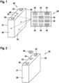
- Fig. 1 schematically shows an exemplary embodiment of a battery cell 20, e.g. a high-performance battery cell 20 and a sensor array 40.
- the battery cell 20 may be used for driving a car, a train, a subway, a bus, etc.
- the high-performance battery cell 20 may have a nominal capacity between 15 Ah and 1.000 Ah.
- the nominal capacity may be between 20 Ah and 500 Ah, e.g. between 25 Ah and 100 Ah.
- the battery cell 20 may comprise a cell body 21 and at least two electrical contacts, in particular a first electrical contact 30 and a second electrical contact 32.
- the electrical contacts 30, 32 may be arranged at opposing sides or at the same side of the cell body 21.
- the electrical contacts 30, 32 may correspond to the poles of the battery cell 20.
- one of the electrical contacts 30, 32 may correspond to the plus-pole and the other one of the electrical contacts 30, 32 may correspond to the minus-pole of the battery cell 20.
- the cell body 21 may comprise a first side 22, a second side 24 a third side 26.
- the first side 22 may be smaller than the second side 24, and the second side 24 may be smaller than the third side 26.
- the cell body 21 may have a prismatic shape.
- the cell body 21 may have a cuboid shape.
- the high-performance battery cell 20 may comprise a vent 28.
- the vent 28 may be configured to release gas from inside of the battery cell 20, if a pressure of the gas exceeds a predetermined gas pressure threshold.
- the vent 28 may comprise or may consist of a vent disc and/or bursting disc.
- the sensor array 40 may comprise two or more wear sensors 42.
- the sensor array 40 comprises 12 wear sensors 42.
- the sensor array 40 may comprise more or less wear sensors 42.
- the battery cell 20 may comprise one wear sensor 42 only.
- the sensor array 40, in particular the wear sensors 42, may be arranged within and/or at the cell body 21 such that it is visible from outside of the cell body 21.
- the wear sensor 42 may be arranged at any position on the cell body 21, e.g. at a bottom of cell body 21, at the first side 22, e.g. close to the vent 28, at the second side 24, e.g. in the centre of the second side 24, or at the third side 26, e.g. in the centre of the third side 26.
- the sensor array 40 may be arranged at the position of the vent 28, wherein the vent 28 may be omitted.
- Each of the wear sensors 42 may be configured for determining at least one wear parameter and for changing its visual appearance depending on the measured wear parameter. So, the sensor array 42 enables to detect and check more than one, e.g. two or more different wear parameters at a time by visual inspection.
- the wear parameters may be one or more of a group of wear parameters, the group comprising HF content, pH-value, ethylene carbonate content, diethyl carbonate content, current within the battery cell, H 2 O content, H 2 content, cell deformation, CO content, C 2 H 4 content, and CO 2 content.
- the HF content and/or the pH-value may be determined to detect a electrolyte salt leakage, e.g. a lithium salt leakage, e.g. a LiPF 6 salt leakage.
- the ethylene carbonate content and/or the diethyl carbonate content may be determined to detect organic solvent leakages.
- the current within the battery cell 20 may be determined to detect an overcharging and/or a short circuit, e.g. by a colorimetric voltmeter.
- the H 2 O content and/or H 2 content may be determined to detect the humidity and/or an immersion history within the battery cell 20.
- the cell deformation may be determined to detect an overpressure within the cell body 21.
- the CO content may be determined to detect toxic and/or flammable gases from the battery cell 20.
- the C 2 H 4 and/or the H 2 content may be determined to detect ageing gases from the battery cell 20.
- Each of the wear sensors 42 may comprise or may be made of at least one of the group of a tape, e.g. a sensing tape and/or an adhesive tape, a coating, a painting, and an integrated chip.
- the sensor array 40, in particular the wear sensors 42 may be attached to the cell body 20 after a battery cell assembly of the battery cell 20 and/or during a battery module and/or battery pack assembly.
- the wear sensors 42 are configured for changing their visual appearance depending on the measured wear parameter by changing at least one of the group of its colour, its shape, its transparency, the amount of its material.
- the amount of the material may change if a part of the wear sensor 42 disappears, e.g. by complete or partly vaporization or melting of the material of the wear sensor 42.
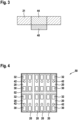
- Fig. 2 schematically shows an exemplary embodiment of a battery cell 20.
- the battery cell 20 may widely correspond to the above the battery cell 20. Therefore, only those features of the battery cell 20 are explained in the following in which the battery cell of figure 2 differs from the above battery cell 20.
- the sensor array 40 may be arranged within the cell body 21.
- the battery cell 20 may comprise a transparent cell window 44 within the cell body 21.
- the sensor array 40 in particular the wear sensors 42, may be arranged within the cell body 21 behind the cell window 44 such that the wear sensor 42 may be visible from outside of the cell body 21 through the cell window 44.
- the cell window 44 may overlap, e.g. completely, the sensor array 40, in particular the wear sensors 42.
- the cell window 44 may be a simple recess within the cell body 21.
- the cell window 44 may be a hollow or hole structure allowing an internal sensor status visibility from outside of the battery cell 20.
- the cell window 44 may be made of a transparent material, e.g. a rigid or flexible material, to allow the internal sensor status visibility from outside of the battery cell 20.
- a status of the battery cell 20 may be checked by a user or service personal by visually checking the appearance of the sensor array 42, e.g. by an eye 46 of the user or of the service personal.
- the status of the battery cell 20 may be checked automatically by a battery management system, as explained below.
- Fig. 3 schematically shows a detailed cross-sectional side view of an exemplary embodiment of a cell window 44 and a sensor array 40 of the battery cell 20 of figure 2 . From figure 3 it may be seen that the sensor array 40 may be arranged directly behind the cell window 44. Instead of the sensor array 40, the battery cell 20 may comprise one single wear sensor 42.
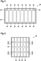
- Fig. 4 schematically shows a cross-sectional top view of an exemplary embodiment of a battery module 50.
- the battery module 50 may comprise at least two, e.g. 12, of the above battery cells 20 and a module housing 52 in which the battery cells 20 are arranged.
- Each of the battery cells 20 may comprise at least one wear sensor 42.
- each of the battery cells 20 may comprise one sensor array 40, with each sensor array 40 comprising at least two of the wear sensors 42.
- Fig. 5 schematically shows a cross sectional side view of the battery module 50 of figure 4 .
- the module housing 52 may comprise a transparent module window 54 for each of the battery cells 20 within the battery module 50.
- the transparent module windows 54 may be arranged such that the corresponding wear sensors 42 are visible from outside of the battery module 50 through the corresponding module window 54.
- the module windows 54 are arranged such that they overlap, e.g. completely, the corresponding sensor array 40 and/or wear sensors 42.
- the module windows 54 each may be a simple recess within the module housing 52.
- the module windows 54 may be hollow or hole structures allowing an internal wear sensor status visibility from outside of the battery module 50.
- the module windows 54 each may be made of a transparent material, e.g. a rigid or flexible material, to allow the internal sensor status visibility from outside of the battery module 50.
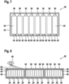
- Fig. 6 schematically shows a cross-sectional bottom view of an exemplary embodiment of a battery module
- Fig. 7 schematically shows a cross sectional side view of the battery module of figure 6 .
- the battery module 50 may widely correspond to the above the battery module 50. Therefore, only those features of the battery module 50 are explained in the following in which the battery module 50 of figures 6 and 7 differs from the above battery module 50.
- the wear sensors 42 may be arranged at the bottom of the corresponding battery cells 20.
- the module windows 54 may be correspondingly arranged at the bottom of the battery module 50.
- Fig. 8 schematically shows a cross sectional side view of an exemplary embodiment of a battery pack 60.
- the battery pack 60 may comprise at least two of the above battery modules 50 and a pack housing 62 in which the battery modules 50 are arranged.
- the battery pack 60 may comprise a transparent pack window 64 for each of the module windows 54, in particular for each of the battery cells 20.
- the pack window 64 may be arranged such that the wear sensors 42 may be visible from outside of the battery pack 60 through the pack windows 64 and the module windows 54.
- the pack windows 64 may be arranged such that they overlap, e.g. completely overlap, the corresponding module windows 54.
- Fig. 9 schematically shows a cross sectional side view of an exemplary embodiment of a battery module 50.
- the battery module 50 may widely correspond to one of the above the battery modules 50. Therefore, only those features of the battery module 50 are explained in the following in which the battery module 50 of figure 9 differs from the above battery modules 50.
- the battery module 50 may comprise at least two of the above battery cells 20, each having the cell body 21 and the at least two electrical contacts 30, 32 and being arranged within the module housing 52.
- the battery module 50 may comprise a first guide unit 56 being arranged within the module housing 52, being coupled to the battery cells 20 and being configured for guiding at least one wear indicator from the battery cells 20 to the wear sensor 42 and if any of the sensor array 40 of the battery module 50.
- the first guide unit may be referred to as first sensing guide channel.
- the first guide unit 50 may be applied to direct signal sources, i.e. wear indicators, to a sensing area provided by the sensor area 40, in particular the wear sensors 42, within the battery module 50.
- the wear indicator may be one or more of a group of wear indicators, the group comprising HF, electrolyte, ethylene carbonate, diethyl carbonate, H 2 O, H 2 , CO, C 2 H 4 , LiPF 6 salt, and CO 2 content.
- the sensor array 40 in particular the wear sensor 42, may be arranged within the battery module 50 such that it is visible from outside of the battery module 50.
- the module housing 52 may comprise the transparent module window 52 which is arranged such that the sensor array 40, in particular the wear sensor 42, may be visible from outside of the battery module 50 through the module window 54.
- Fig. 10 schematically shows a cross sectional side view of an exemplary embodiment of a battery module 50.
- the battery module 50 may widely correspond to one of the above the battery modules 50. Therefore, only those features of the battery module 50 are explained in the following in which the battery module 50 of figure 12 differs from the above battery modules 50.
- the sensor array 40 and/or the wear sensors 42 may be arranged at an outer surface of the module housing 52 of the battery module 50.
- the first guide unit 56 may be guided through the module housing 52 to the sensor array 40 and/or wear sensors 42.
- the module housing 52 may comprise a recess through which the first guide unit 56 may extend.
- Fig. 11 schematically shows a cross sectional side view of an exemplary embodiment of a battery pack 60.
- the battery pack 60 may widely correspond to the above battery pack 60. Therefore, only those features of the battery pack 60 are explained in the following in which the battery pack 60 of figure 11 differs from the above battery pack 60.
- the battery pack 60 may comprise two or more of the battery modules 50 explained with respect to figure 9 .
- the battery pack 60 may comprise two or more of the battery modules 50 explained with respect to figure 10 .
- the pack windows 64 and the battery modules 50 may be arranged such that the sensor arrays 40, in particular the wear sensors 42, may be visible from outside of the battery pack 60 through the corresponding pack windows 64 and corresponding module windows 54.
- the pack window 64 are arranged such that they overlap, e.g. completely, the corresponding module windows 54.
- Fig. 12 schematically shows a cross sectional side view of an exemplary embodiment of a battery pack 60.
- the battery pack 60 may widely correspond to one of the above battery packs 60. Therefore, only those features of the battery pack 60 are explained in the following in which the battery pack 60 of figure 12 differs from the above battery packs 60.
- the battery pack 60 may comprise the battery modules 50 each comprising one of the above first guide units 56.
- the first guide units 56 may be coupled to the corresponding battery cells 20 and may be configured for guiding at least one of the above wear indicators from the battery cells 20 to a second guide unit 66 of the battery pack 60.
- the second guide unit may be referred to as second sensing guide channel.
- the second guide unit 66 may be arranged within the battery pack 60 outside of the battery modules 50.
- the second guide unit 66 may be coupled to the first guide unit 56 and may be configured for guiding the at least one wear indicator from the first guide unit 56 to the sensor array 40 and/or the corresponding wear sensor 42.
- the sensor array 40 and/or, respectively, the wear sensor 42 may be arranged at an outer surface of the battery pack 60.
- the pack housing 62 may comprise recess through which the second guide unit 66 extends to the sensor array 40 and/or, respectively, the wear sensor 42.
- the battery pack 60 may comprise one of the above transparent pack windows 64, wherein the sensor array 40 and/or, respectively, the wear sensor 42 may be arranged within the battery pack 60 behind the pack window 64 such that the sensor array 40 and/or, respectively, the wear sensor 42 may be visible from outside of the battery pack 60 through the pack window 64.
- Fig. 13 schematically illustrates a working principle of an exemplary embodiment of a battery management system 74.
- the battery management system 74 may be arranged for checking, in particular automatically, the wear state of one or more of the above battery cells 20.
- the battery cells 20 may stand alone or may be arranged in one of the above battery modules 50, wherein the battery modules 50 optionally may be arranged within one of the above battery packs 60.
- the battery management system 74 may comprise an optical sensor 72 and a controller 76.
- the optical sensor 72 may be a camera, e.g. a digital camera, e.g. a CCD-camera.
- the optical sensor 72 may be configured for detecting the visual appearance of the sensor array 40 and/or the wear sensor(s) 42 of the battery cell 20, the battery module 50 and/or, respectively, the battery pack 60, e.g. through the cell window 44, the module window 54 or, respectively, the pack window 64.
- the optical sensor 72 may be configured for generating a signal representing the visual appearance of the wear sensor(s) 42.
- the optical sensor 72 may be arranged such that the sensor array 40 and/or the wear sensor(s) 42 are arranged within a field of view of the optical sensor 72.
- the controller 76 may be or may comprise a chip and/or an integrated circuit.
- the controller 76 may be coupled to the optical sensor 72 for receiving a signal of the optical sensor 72.
- the controller 76 may be configured for determining a value of the wear parameter depending on the signal of the optical sensor 72 representing the visual appearance of the wear sensor(s) 42.
- the sensor array 40 and/or the wear sensors 42 may be arranged such that they come in direct physical contact with the wear indicator 70.
- Fig. 14 schematically illustrates a working principle of an exemplary embodiment of a battery management system 74.
- the battery management system 74 may widely correspond to the above battery management system 74. Therefore, only those features of the battery management system 74 are explained in the following in which the battery management system 74 of figure 14 differs from the above battery management system 74.
- the battery management system 74 may be arranged for checking, in particular automatically, the wear state of the battery module 50 explained with respect to figure 5 .
- the battery management system 74 may be arranged for checking the wear state of any of the battery cells 20, battery modules 50, and/or battery packs 60, as explained above.
- the battery management system 74 may comprise one single optical sensor 72 (not shown in figure 14 ), as explained with respect to figure 13 , and at least one light guiding structure, e.g. an optical fibre, guiding the light from the module windows 54 to the controller 76.
- the battery management system 74 may comprise more than one optical sensor 72 (not shown in figure 14 ), as explained with respect to figure 13 , e.g. one for each of the module windows 54.
- Fig. 15 schematically shows a flow diagram of an exemplary embodiment of a method for determining a value of at least one wear parameter of one or more of the above battery cells 20, battery modules 50 and/or battery packs 60.
- the method may be embodied as a computer program.
- the computer program may be carried out by a processor of the controller 76 of the battery management system 74.
- the computer program may be stored in a memory of the controller 76 of the battery management system 74.
- step S2 it may be determined whether the battery cell 20, battery module 50, and/or battery pack 60 are in rest time or in normal operation. Alternatively or additionally, it may be determined whether a service life of the battery cell 20, the battery module 50, and/or the battery pack 60 has ended.
- step S4 a signal representing the visual appearance of the sensor array 40, in particular of one or more wear sensors 42, coupled to the battery cell 20, the battery module 50 and/or the battery pack 60 may be received.
- the signal may be generated by the optical sensor 72 and may be sent to the controller 76 receiving the signal.
- a value of the wear parameter may be determined depending on the visual appearance of the wear sensor 42.
- the data encoded within the signal may be processed by an image analysing program running on the controller 76.
- the image analysing program may be a conventional image analysing program configured for analysing the visual appearance of the sensor array 40 and/or the wear sensors 42 depending on the data encoded within the signal.
- a neural network may be used to determine the value of the real parameter depending on the data.
- the neural network may be trained by a training data set in advance to determine the value of the real parameter depending on the data.
- the training may be a supervised training.
- the training data set may comprise data representing the visual appearance of a huge amount of sensor arrays 40 and/or the wear sensors 42 in different wear states, wherein the features for the training may be extracted from the data and wherein the values of the wear parameters may be the labels for the training.
- a step S8 it may be determined whether the battery cell 20, the battery module 50 and/or the battery pack 60 under investigation may be used further, may have to be repaired, or may have to be replaced depending on the determined value of the wear parameters. For example, a table assigning the different actions to different values of the wear parameters may be stored in the memory of the controller 74 for this reason. If it is determined that the battery cell 20, the battery module 50 and/or the battery pack 60 under investigation may be used further, the method may be terminated.
- a step S10 may be carried out, if the battery cell 20, the battery module 50 and/or the battery pack 60 under investigation may be used further but may have to be repaired.
- a signal may be generated, the signal indicating that the battery cell 20, the battery module 50 and/or the battery pack 60 under investigation may be used further but may have to be repaired.
- a step S12 may be carried out, if the battery cell 20, the battery module 50 and/or the battery pack 60 under investigation may have to be replaced.
- a signal may be generated, the signal indicating that the battery cell 20, the battery module 50 and/or the battery pack 60 under investigation may be used further but may have to be replaced.
- a step S14 may be carried out, if the battery cell 20, the battery module 50 and/or the battery pack 60 under investigation may have to be recycled.
- a signal may be generated, the signal indicating that the battery module 50 and/or the battery pack 60 under investigation may have to be recycled.
Landscapes
- Engineering & Computer Science (AREA)
- Chemical & Material Sciences (AREA)
- Chemical Kinetics & Catalysis (AREA)
- Electrochemistry (AREA)
- General Chemical & Material Sciences (AREA)
- Manufacturing & Machinery (AREA)
- Microelectronics & Electronic Packaging (AREA)
- Secondary Cells (AREA)
- Battery Mounting, Suspending (AREA)
Abstract
Description
- The invention relates to the field of battery cells, battery modules and battery packs. In particular, the invention relates to a battery cell, a battery module comprising the battery cell, a battery pack comprising the battery module, a battery management system for checking a wear state of one or more of the battery cells and a method for determining a value of at least one wear parameter of one of the battery cells.
- An increasing number of vehicles, e.g. cars, trains, subways, busses, is equipped with high-performance battery cells. A typical high-performance battery cell may have a nominal capacity between 1 Ah and 1000 Ah and may be used for driving the corresponding vehicle, in particular for providing a power train of the corresponding vehicle with energy.
- Conventional high-performance battery cells may be fully assembled and encapsulated in modules. Then, the modules may be combined and encapsulated as battery packages. These battery packages may be arranged in the vehicles. In the most cases, the battery packages are not designed to be removed easily, e.g. in order to check and/or substitute one or more of the battery cells. In contrast, it is common practice that intense efforts have to be taken to check a wear status of the battery cells within the battery modules within the battery packages.
- The battery cells, in particular the high-performance battery cells, comprise e.g. lithium-ion cells and sodium-ion cells. The Li-ion cells may fail in non-energetic and energetic modes. Non-energetic cell failures, which show no thermal runway but cause the permanent or irreversible damage to the cell, may mainly affect the reliability of the battery. Non-energetic failures may include capacity fading, internal resistance increase, cell swelling, electrolyte leakage and the consequent cell dry-out. Sometimes, in a later stage in time, non-energetic failures may be associated with not only the cell ageing process but also the root cause of later energetic failures. Energetic cell failures may be associated with a self-sustaining exothermic reaction within the cell, e.g. leading to thermal runaway.
- Abnormal or abused, in other words worn out battery cells may lead to a failure of the whole battery module and/or battery pack. For safety concerns, it may be crucial to detect those non-energetic battery cell failures before the energetic failures occur.
- Second-life application and recycling may be two approaches to improve a battery sustainability. Today, it is a challenge to separate worn out batteries from batteries with good conditions, normally requiring a sophisticated electrical test. This may result in high costs and/or safety risks of the second-life applications. Thus, the problem of low-efficient and high-cost battery sorting may have to be addressed.
-
CN 103 545 567 A describes to sort out battery cells based on a capacity and an internal resistance of the corresponding battery cells. However, an electrical test may be required for each battery cell to test. -
JPH 10 172 618 A - An alternative approach may be the sorting based on an electrochemical impedance spectroscopy (EIS) and its equivalent model parameters, and/or based on a charge and discharge voltage curve of the corresponding battery cells. The disadvantage with these approaches may be that an electrical test may be required for each battery cell to test.
-
KR 2014 032 917 A US 2006 00 08 699 A1 suggest a detection of overheated cells with a thermochromic indicator. However, the overheating information alone may not be sufficient to finally judge the battery condition. For example, a cell could be exposed to the high temperature, e.g. more than 50°C, in a very short period, which may cause no ageing reactions. In order to verify whether there is a severe problem the battery pack and module may have to be disassembled to check the overheating information, which may be destructive to the module and pack. - Therefore, it is an objective of the present invention to provide a battery cell which may enable checking a wear state of the battery cell, in other words wear conditions of the battery cell, and/or battery sorting to improve battery safety and reliability. In particular, an economic and comprehensive solution may be provided to examine and sort out worn-out abnormal battery cells during the operation, during the rest time, or after the service life. Different inspection approaches are disclosed to evaluate the battery conditions without opening the battery module and pack. Workflows for fast battery sorting are concluded. Such a solution could be served as a fast and easy diagnostic tool for BESS (battery energy storage system) service engineers.
- Further, it is an objective of the present invention to provide a battery module which may enable checking a wear state of battery cells of the battery module, in other words wear conditions of the battery cells, and/or which may enable the battery sorting of the battery cells to improve battery module safety and reliability in an easy and cost-efficient way.
- Further, it is an objective of the present invention to provide a battery pack which may enable checking a wear state of battery cells of battery modules of the battery pack, in other words wear conditions of the battery cells, and/or which may enable the battery sorting of the battery cells to improve battery pack safety and reliability in an easy and cost-efficient way.
- Furthermore, it is an objective of the present invention to provide a Battery Management System (BMS) for checking a wear state of one or more battery cells in a simple and cost-efficient way.
- Furthermore, it is an objective of the present invention to provide a method for determining a value of at least one wear parameter of one of the battery cells, one of the battery modules and/or the battery pack in a simple and cost-efficient way.
- These objectives are achieved by the subject-matter of the independent claims. Further exemplary embodiments are evident from the dependent claims and the following description.
- In particular, an objective of the present invention is achieved by a battery cell, comprising a cell body, at least two electrical contacts, and at least one wear sensor being arranged within and/or at the cell body such that it is visible from outside of the cell body and being configured for determining at least one wear parameter and for changing its visual appearance depending on the measured wear parameter.
- The battery cell enables a visual diagnostic method to indicate a battery condition, in particular a wear state, e.g. a State Of Health (SOH), of the battery cell. In addition, BESS (Battery Energy Storage System) service engineers may easily inspect and evaluate the battery conditions from outside of the battery cell. Therefore the battery cell enables checking the wear state of the battery cell, in other words wear conditions of the battery cell, and/or battery sorting to improve battery safety and reliability, in an easy and cost-efficient way.
- The battery cell may be a high-performance battery cell having a nominal capacity between 1 Ah and 1000 Ah. The nominal capacity may be between 20 Ah and 500 Ah, e.g. between 25 Ah and 100 Ah. The electrical contacts may be arranged at opposing sides of the cell body. The electrical contacts may correspond to the poles of the battery cell. For example, one of the electrical contacts may correspond to the plus-pole and the other one of the electrical contacts may correspond to the minus-pole of the battery cell. The cell body may have a prismatic shape. For example, the cell body may have a cuboid shape.
- According to an embodiment, the battery cell comprises a transparent cell window within the cell body, wherein the wear sensor is arranged within the cell body behind the cell window such that the wear sensor is visible from outside of the cell body through the cell window. The cell window may be a simple recess within the cell body. For example, the cell window may be a hollow or hole structure allowing an internal sensor status visibility from outside of the battery cell. For example, the position of the wear sensor may replace a position of a vent disc of the battery cell. Alternatively, the cell window may be made of a transparent material, e.g. a rigid or flexible material, to allow the internal sensor status visibility from outside of the battery cell. The wear sensor may be arranged at any place inside the cell body.
- Alternatively, the wear sensor may be arranged at an outer surface of the cell body such that it is visible without the need for any cell window. For example, the wear sensor may be arranged at a bottom or centre of cell body, or close to the vent disc, etc.
- According to an embodiment, the at least one wear parameter is one of a group of wear parameters, the group comprising hydrogen fluoride (HF) content, pH-value, ethylene carbonate content, diethyl carbonate content, current within the battery cell, H2O content, H2 content, cell deformation, CO content, C2H4 content, and CO2 content. The HF content and/or the pH-value may be determined to detect an electrolyte salt leakage, e.g. a lithium salt leakage, e.g. a LiPF6 salt leakage. The ethylene carbonate content and/or the diethyl carbonate content may be determined to detect organic solvent leakages. The current within the battery cell may be determined to detect an overcharging and/or a short circuit, e.g. by a colorimetric voltmeter. The H2O content and/or H2 content may be determined to detect the humidity and/or an immersion history within the battery cell. The cell deformation may be determined to detect an overpressure within the cell body. The CO content may be determined to detect toxic and/or flammable gases from the battery cell. The C2H4 and/or the H2 content may be determined to detect ageing gases from the battery cell.
- According to an embodiment, the wear sensor comprises at least one of the group of a tape, a coating, a painting, an integrated chip.
- According to an embodiment, the wear sensor is configured for changing its visual appearance depending on the measured wear parameter by changing at least one of the group of its colour, its shape, its transparency, the amount of its material. The amount of the material may change if a part of the wear sensor disappears, e.g. by complete or partly vaporization or melting of the material of the wear sensor.
- According to an embodiment, the battery cell comprises a sensor array comprising the wear sensor and at least one further wear sensor being arranged within and/or at the cell body such that it is visible from outside of the cell body and being configured for determining at least one further wear parameter and for changing its visual appearance depending on the measured further wear parameter. The sensor array enables to detect and check more than one, e.g. two or more different wear parameters at a time in an easy and cost-efficient way.
- An objective of the present invention is achieved by a battery module, comprising at least two of the above battery cells and a module housing in which the battery cells are arranged and which comprises a transparent module window which is arranged such that the wear sensor is visible from outside of the battery module through the module window. The module window may be a simple recess within the module housing. For example, the module window may be a hollow or hole structure allowing an internal wear sensor status visibility from outside of the module. Alternatively, the module window may be made of a transparent material, e.g. a rigid or flexible material, to allow the internal sensor status visibility from outside of the module.
- The above features, advantages and/or effects of the battery cell may be transferred to the above battery module. Therefore, a repetition of these features, advantages and/or effects is omitted and it is referred to the above explanations only in order to provide a concise description.
- An objective of the present invention is achieved by a battery module comprising: at least two battery cells having a cell body and at least two electrical contacts; a first guide unit coupled to the battery cells and being configured for guiding at least one wear indicator from the battery cells to a wear sensor; and the wear sensor being arranged within and/or at the battery module such that it is visible from outside of the battery module and being configured for determining at least one wear parameter from the wear indicator and for changing its visual appearance depending on the measured wear parameter. The first guide unit may be referred to as first sensing guide channel. The first guide unit may be applied to direct signal sources, i.e. wear indicators, to a sensing area provided by the wear sensor within or outside of the battery module.
- The above features, advantages and/or effects of the battery cell may be transferred to the above battery module. Therefore, a repetition of these features, advantages and/or effects is omitted and it is referred to the above explanations only in order to provide a concise description.
- According to an embodiment, the battery module comprises a module housing in which the battery cells, the first guide unit and the wear sensor are arranged, the module housing comprising a transparent module window which is arranged such that the wear sensor is visible from outside of the battery module through the module window. The module window may be a simple recess within the module housing. For example, the module window may be a hollow or hole structure allowing an internal wear sensor status visibility from outside of the module. Alternatively, the module window may be made of a transparent material, e.g. a rigid or flexible material, to allow the internal sensor status visibility from outside of the module.
- Alternatively, according to another embodiment, the battery module comprises a module housing in which the battery cells and the guide unit are arranged, wherein the wear sensor is arranged at an outer surface of the module housing and wherein the first guide unit is guided through the module housing to the wear sensor.
- An objective of the present invention is achieved by a battery pack comprising at least two of the above battery modules and a pack housing, in which the battery modules are arranged and which comprises a transparent pack window which is arranged such that the wear sensor is visible from outside of the battery pack through the pack window, and if any through the corresponding module window.
- The above features, advantages and/or effects of the battery cell and/or the battery module may be transferred to the battery pack. Therefore, a repetition of these features, advantages and/or effects is omitted and it is referred to the above explanations only in order to provide a concise description.
- An objective of the present invention is achieved by a battery pack, comprising: at least two of the battery modules each comprising at least two of the battery cells each having a cell body and at least two electrical contacts and a first guide unit being arranged within the corresponding battery module. The first guide unit may be coupled to the corresponding battery cells and may be configured for guiding at least one wear indicator from the battery cells to a second guide unit. The second guide unit may be arranged within the battery pack but outside of the battery modules. The second guide unit may be coupled to the first guide unit and may be configured for guiding the at least one wear indicator from the first guide unit to the wear sensor. The wear sensor may be arranged within and/or at the battery pack such that it is visible from outside of the battery pack and may be configured for determining the at least one wear parameter from the wear indicator and for changing its visual appearance depending on the measured wear parameter.
- The above features, advantages and/or effects of the battery cell and/or the battery module may be transferred to the battery pack. Therefore, a repetition of these features, advantages and/or effects is omitted and it is referred to the above explanations only in order to provide a concise description.
- According to an embodiment, the battery pack comprises a transparent pack window within the battery pack, wherein the wear sensor is arranged within the battery pack behind the pack window such that the wear sensor is visible from outside of the battery pack through the pack window.
- An objective of the present invention is achieved by a battery management system for checking a wear state of one or more battery cells. The battery management system comprises at least one optical sensor being configured for detecting the visual appearance of the wear sensor of one or more of the above battery cells, battery modules and/or battery packs. The optical sensor may be configured for generating a signal representing the visual appearance of the wear sensor. A controller of the BMS may be coupled to the optical sensor and may be configured to receive the signal from the optical sensor and for determining a value of the wear parameter depending on the visual appearance of the wear sensor.
- The above features, advantages and/or effects of the battery cell, the battery module and/or the battery pack may be transferred to the battery arrangement system. Therefore, a repetition of these features, advantages and/or effects is omitted and it is referred to the above explanations only in order to provide a concise description.
- An objective of the present invention is achieved by a method for determining the value of the one or more wear parameters of one or more of the above battery cells, battery modules and/or battery packs. The method comprises the steps of receiving a signal representing the visual appearance of the wear sensor of the battery cell, the battery module and/or the battery pack; and determining a value of the wear parameter depending on the visual appearance of the wear sensor. The method represents a visual diagnostic method to indicate the battery conditions, in particular by sensing of the wear state for battery safety, including leakage, swelling, cell deformation, and/or overcharging without changing inside parts of the cell.
- The above features, advantages and/or effects of the battery cell, the battery module and/or the battery pack may be transferred to the method for determining a value of at least one wear parameter of one of the above battery cell, battery module and/or battery pack. Therefore, a repetition of these features, advantages and/or effects is omitted and it is referred to the above explanations only in order to provide a concise description.
- These and other aspects of the invention will be apparent from and elucidated with reference to the embodiments described hereinafter.
- The subject matter of the invention will be explained in more detail in the following text with reference to exemplary embodiments which are illustrated in the attached drawings.
-
Fig. 1 schematically shows an exemplary embodiment of a battery cell and a sensor array; -
Fig. 2 schematically shows an exemplary embodiment of a battery cell; -
Fig. 3 schematically shows a detailed cross-sectional view of an exemplary embodiment of a cell window and a sensor array of the battery cell offigure 2 ; -
Fig. 4 schematically shows a cross-sectional top view of an exemplary embodiment of a battery module; -
Fig. 5 schematically shows a cross sectional side view of the battery module offigure 4 ; -
Fig. 6 schematically shows a bottom view an exemplary embodiment of a battery module; -
Fig. 7 schematically shows a cross sectional side view of the battery module offigure 6 ; -
Fig. 8 schematically shows a cross sectional side view of an exemplary embodiment of a battery pack; -
Fig. 9 schematically shows a cross sectional side view of an exemplary embodiment of a battery module; -
Fig. 10 schematically shows a cross sectional side view of an exemplary embodiment of a battery module; -
Fig. 11 schematically shows a cross sectional side view of an exemplary embodiment of a battery pack; -
Fig. 12 schematically shows a cross sectional side view of an exemplary embodiment of a battery pack; -
Fig. 13 schematically illustrates a working principle of an exemplary embodiment of a battery management system; -
Fig. 14 schematically illustrates a working principle of an exemplary embodiment of a battery management system; -
Fig. 15 schematically shows a flow diagram of an exemplary embodiment of a method for determining a value of at least one wear parameter of a battery cell, a battery module and/or a battery pack. - The reference symbols used in the drawings, and their meanings, are listed in summary form in the list of reference symbols. In principle, identical parts are provided with the same reference symbols in the figures.
-
Fig. 1 schematically shows an exemplary embodiment of abattery cell 20, e.g. a high-performance battery cell 20 and asensor array 40. For example, thebattery cell 20 may be used for driving a car, a train, a subway, a bus, etc. - The high-
performance battery cell 20 may have a nominal capacity between 15 Ah and 1.000 Ah. The nominal capacity may be between 20 Ah and 500 Ah, e.g. between 25 Ah and 100 Ah. Thebattery cell 20 may comprise acell body 21 and at least two electrical contacts, in particular a firstelectrical contact 30 and a secondelectrical contact 32. Theelectrical contacts cell body 21. Theelectrical contacts battery cell 20. For example, one of theelectrical contacts electrical contacts battery cell 20. - The
cell body 21 may comprise afirst side 22, a second side 24 athird side 26. Thefirst side 22 may be smaller than thesecond side 24, and thesecond side 24 may be smaller than thethird side 26. Optionally, thecell body 21 may have a prismatic shape. For example, thecell body 21 may have a cuboid shape. - The high-
performance battery cell 20 may comprise avent 28. Thevent 28 may be configured to release gas from inside of thebattery cell 20, if a pressure of the gas exceeds a predetermined gas pressure threshold. For example, thevent 28 may comprise or may consist of a vent disc and/or bursting disc. - The
sensor array 40 may comprise two ormore wear sensors 42. For example, thesensor array 40 comprises 12wear sensors 42. Alternatively, thesensor array 40 may comprise more or less wearsensors 42. Alternatively, thebattery cell 20 may comprise onewear sensor 42 only. Thesensor array 40, in particular thewear sensors 42, may be arranged within and/or at thecell body 21 such that it is visible from outside of thecell body 21. - If the
sensor array 40 is arranged at an outer surface of thecell body 21, as shown infigure 1 , thewear sensor 42 may be arranged at any position on thecell body 21, e.g. at a bottom ofcell body 21, at thefirst side 22, e.g. close to thevent 28, at thesecond side 24, e.g. in the centre of thesecond side 24, or at thethird side 26, e.g. in the centre of thethird side 26. For example, thesensor array 40 may be arranged at the position of thevent 28, wherein thevent 28 may be omitted. - Each of the
wear sensors 42 may be configured for determining at least one wear parameter and for changing its visual appearance depending on the measured wear parameter. So, thesensor array 42 enables to detect and check more than one, e.g. two or more different wear parameters at a time by visual inspection. The wear parameters may be one or more of a group of wear parameters, the group comprising HF content, pH-value, ethylene carbonate content, diethyl carbonate content, current within the battery cell, H2O content, H2 content, cell deformation, CO content, C2H4 content, and CO2 content. The HF content and/or the pH-value may be determined to detect a electrolyte salt leakage, e.g. a lithium salt leakage, e.g. a LiPF6 salt leakage. The ethylene carbonate content and/or the diethyl carbonate content may be determined to detect organic solvent leakages. The current within thebattery cell 20 may be determined to detect an overcharging and/or a short circuit, e.g. by a colorimetric voltmeter. The H2O content and/or H2 content may be determined to detect the humidity and/or an immersion history within thebattery cell 20. The cell deformation may be determined to detect an overpressure within thecell body 21. The CO content may be determined to detect toxic and/or flammable gases from thebattery cell 20. The C2H4 and/or the H2 content may be determined to detect ageing gases from thebattery cell 20. - Each of the
wear sensors 42 may comprise or may be made of at least one of the group of a tape, e.g. a sensing tape and/or an adhesive tape, a coating, a painting, and an integrated chip. Thesensor array 40, in particular thewear sensors 42 may be attached to thecell body 20 after a battery cell assembly of thebattery cell 20 and/or during a battery module and/or battery pack assembly. - The
wear sensors 42 are configured for changing their visual appearance depending on the measured wear parameter by changing at least one of the group of its colour, its shape, its transparency, the amount of its material. The amount of the material may change if a part of thewear sensor 42 disappears, e.g. by complete or partly vaporization or melting of the material of thewear sensor 42. -
Fig. 2 schematically shows an exemplary embodiment of abattery cell 20. Thebattery cell 20 may widely correspond to the above thebattery cell 20. Therefore, only those features of thebattery cell 20 are explained in the following in which the battery cell offigure 2 differs from theabove battery cell 20. - The
sensor array 40 may be arranged within thecell body 21. In this case, thebattery cell 20 may comprise atransparent cell window 44 within thecell body 21. Thesensor array 40, in particular thewear sensors 42, may be arranged within thecell body 21 behind thecell window 44 such that thewear sensor 42 may be visible from outside of thecell body 21 through thecell window 44. Thecell window 44 may overlap, e.g. completely, thesensor array 40, in particular thewear sensors 42. Thecell window 44 may be a simple recess within thecell body 21. For example, thecell window 44 may be a hollow or hole structure allowing an internal sensor status visibility from outside of thebattery cell 20. Alternatively, thecell window 44 may be made of a transparent material, e.g. a rigid or flexible material, to allow the internal sensor status visibility from outside of thebattery cell 20. - A status of the
battery cell 20 may be checked by a user or service personal by visually checking the appearance of thesensor array 42, e.g. by aneye 46 of the user or of the service personal. Alternatively, the status of thebattery cell 20 may be checked automatically by a battery management system, as explained below. -
Fig. 3 schematically shows a detailed cross-sectional side view of an exemplary embodiment of acell window 44 and asensor array 40 of thebattery cell 20 offigure 2 . Fromfigure 3 it may be seen that thesensor array 40 may be arranged directly behind thecell window 44. Instead of thesensor array 40, thebattery cell 20 may comprise onesingle wear sensor 42. -
Fig. 4 schematically shows a cross-sectional top view of an exemplary embodiment of abattery module 50. Thebattery module 50 may comprise at least two, e.g. 12, of theabove battery cells 20 and amodule housing 52 in which thebattery cells 20 are arranged. Each of thebattery cells 20 may comprise at least onewear sensor 42. For example, each of thebattery cells 20 may comprise onesensor array 40, with eachsensor array 40 comprising at least two of thewear sensors 42. -
Fig. 5 schematically shows a cross sectional side view of thebattery module 50 offigure 4 . Themodule housing 52 may comprise atransparent module window 54 for each of thebattery cells 20 within thebattery module 50. Thetransparent module windows 54 may be arranged such that thecorresponding wear sensors 42 are visible from outside of thebattery module 50 through thecorresponding module window 54. For example, themodule windows 54 are arranged such that they overlap, e.g. completely, the correspondingsensor array 40 and/or wearsensors 42. - The
module windows 54 each may be a simple recess within themodule housing 52. For example, themodule windows 54 may be hollow or hole structures allowing an internal wear sensor status visibility from outside of thebattery module 50. Alternatively, themodule windows 54 each may be made of a transparent material, e.g. a rigid or flexible material, to allow the internal sensor status visibility from outside of thebattery module 50. -
Fig. 6 schematically shows a cross-sectional bottom view of an exemplary embodiment of a battery module andFig. 7 schematically shows a cross sectional side view of the battery module offigure 6 . Thebattery module 50 may widely correspond to the above thebattery module 50. Therefore, only those features of thebattery module 50 are explained in the following in which thebattery module 50 offigures 6 and7 differs from theabove battery module 50. - The
wear sensors 42, or alternatively thesensor arrays 40, may be arranged at the bottom of thecorresponding battery cells 20. Themodule windows 54 may be correspondingly arranged at the bottom of thebattery module 50. -
Fig. 8 schematically shows a cross sectional side view of an exemplary embodiment of abattery pack 60. Thebattery pack 60 may comprise at least two of theabove battery modules 50 and apack housing 62 in which thebattery modules 50 are arranged. Thebattery pack 60 may comprise atransparent pack window 64 for each of themodule windows 54, in particular for each of thebattery cells 20. Thepack window 64 may be arranged such that thewear sensors 42 may be visible from outside of thebattery pack 60 through thepack windows 64 and themodule windows 54. For example, thepack windows 64 may be arranged such that they overlap, e.g. completely overlap, the correspondingmodule windows 54. -
Fig. 9 schematically shows a cross sectional side view of an exemplary embodiment of abattery module 50. Thebattery module 50 may widely correspond to one of the above thebattery modules 50. Therefore, only those features of thebattery module 50 are explained in the following in which thebattery module 50 offigure 9 differs from theabove battery modules 50. - The
battery module 50 may comprise at least two of theabove battery cells 20, each having thecell body 21 and the at least twoelectrical contacts module housing 52. Thebattery module 50 may comprise afirst guide unit 56 being arranged within themodule housing 52, being coupled to thebattery cells 20 and being configured for guiding at least one wear indicator from thebattery cells 20 to thewear sensor 42 and if any of thesensor array 40 of thebattery module 50. The first guide unit may be referred to as first sensing guide channel. Thefirst guide unit 50 may be applied to direct signal sources, i.e. wear indicators, to a sensing area provided by thesensor area 40, in particular thewear sensors 42, within thebattery module 50. The wear indicator may be one or more of a group of wear indicators, the group comprising HF, electrolyte, ethylene carbonate, diethyl carbonate, H2O, H2, CO, C2H4, LiPF6 salt, and CO2 content. - The
sensor array 40, in particular thewear sensor 42, may be arranged within thebattery module 50 such that it is visible from outside of thebattery module 50. In particular, themodule housing 52 may comprise thetransparent module window 52 which is arranged such that thesensor array 40, in particular thewear sensor 42, may be visible from outside of thebattery module 50 through themodule window 54. -
Fig. 10 schematically shows a cross sectional side view of an exemplary embodiment of abattery module 50. Thebattery module 50 may widely correspond to one of the above thebattery modules 50. Therefore, only those features of thebattery module 50 are explained in the following in which thebattery module 50 offigure 12 differs from theabove battery modules 50. - The
sensor array 40 and/or thewear sensors 42 may be arranged at an outer surface of themodule housing 52 of thebattery module 50. Thefirst guide unit 56 may be guided through themodule housing 52 to thesensor array 40 and/or wearsensors 42. For example, themodule housing 52 may comprise a recess through which thefirst guide unit 56 may extend. -
Fig. 11 schematically shows a cross sectional side view of an exemplary embodiment of abattery pack 60. Thebattery pack 60 may widely correspond to theabove battery pack 60. Therefore, only those features of thebattery pack 60 are explained in the following in which thebattery pack 60 offigure 11 differs from theabove battery pack 60. - For example, the
battery pack 60 may comprise two or more of thebattery modules 50 explained with respect tofigure 9 . Alternatively, thebattery pack 60 may comprise two or more of thebattery modules 50 explained with respect tofigure 10 . Thepack windows 64 and thebattery modules 50 may be arranged such that thesensor arrays 40, in particular thewear sensors 42, may be visible from outside of thebattery pack 60 through thecorresponding pack windows 64 andcorresponding module windows 54. For example, thepack window 64 are arranged such that they overlap, e.g. completely, the correspondingmodule windows 54. -
Fig. 12 schematically shows a cross sectional side view of an exemplary embodiment of abattery pack 60. Thebattery pack 60 may widely correspond to one of the above battery packs 60. Therefore, only those features of thebattery pack 60 are explained in the following in which thebattery pack 60 offigure 12 differs from the above battery packs 60. - The
battery pack 60 may comprise thebattery modules 50 each comprising one of the abovefirst guide units 56. Thefirst guide units 56 may be coupled to thecorresponding battery cells 20 and may be configured for guiding at least one of the above wear indicators from thebattery cells 20 to asecond guide unit 66 of thebattery pack 60. The second guide unit may be referred to as second sensing guide channel. Thesecond guide unit 66 may be arranged within thebattery pack 60 outside of thebattery modules 50. Thesecond guide unit 66 may be coupled to thefirst guide unit 56 and may be configured for guiding the at least one wear indicator from thefirst guide unit 56 to thesensor array 40 and/or thecorresponding wear sensor 42. For example, thesensor array 40 and/or, respectively, thewear sensor 42, may be arranged at an outer surface of thebattery pack 60. For example, thepack housing 62 may comprise recess through which thesecond guide unit 66 extends to thesensor array 40 and/or, respectively, thewear sensor 42. - Alternatively, the
battery pack 60 may comprise one of the abovetransparent pack windows 64, wherein thesensor array 40 and/or, respectively, thewear sensor 42 may be arranged within thebattery pack 60 behind thepack window 64 such that thesensor array 40 and/or, respectively, thewear sensor 42 may be visible from outside of thebattery pack 60 through thepack window 64. -
Fig. 13 schematically illustrates a working principle of an exemplary embodiment of abattery management system 74. Thebattery management system 74 may be arranged for checking, in particular automatically, the wear state of one or more of theabove battery cells 20. Thebattery cells 20 may stand alone or may be arranged in one of theabove battery modules 50, wherein thebattery modules 50 optionally may be arranged within one of the above battery packs 60. - The
battery management system 74 may comprise anoptical sensor 72 and acontroller 76. Theoptical sensor 72 may be a camera, e.g. a digital camera, e.g. a CCD-camera. Theoptical sensor 72 may be configured for detecting the visual appearance of thesensor array 40 and/or the wear sensor(s) 42 of thebattery cell 20, thebattery module 50 and/or, respectively, thebattery pack 60, e.g. through thecell window 44, themodule window 54 or, respectively, thepack window 64. Theoptical sensor 72 may be configured for generating a signal representing the visual appearance of the wear sensor(s) 42. In particular, theoptical sensor 72 may be arranged such that thesensor array 40 and/or the wear sensor(s) 42 are arranged within a field of view of theoptical sensor 72. - The
controller 76 may be or may comprise a chip and/or an integrated circuit. Thecontroller 76 may be coupled to theoptical sensor 72 for receiving a signal of theoptical sensor 72. Thecontroller 76 may be configured for determining a value of the wear parameter depending on the signal of theoptical sensor 72 representing the visual appearance of the wear sensor(s) 42. - The
sensor array 40 and/or thewear sensors 42 may be arranged such that they come in direct physical contact with thewear indicator 70. -
Fig. 14 schematically illustrates a working principle of an exemplary embodiment of abattery management system 74. Thebattery management system 74 may widely correspond to the abovebattery management system 74. Therefore, only those features of thebattery management system 74 are explained in the following in which thebattery management system 74 offigure 14 differs from the abovebattery management system 74. - The
battery management system 74 may be arranged for checking, in particular automatically, the wear state of thebattery module 50 explained with respect tofigure 5 . However, thebattery management system 74 may be arranged for checking the wear state of any of thebattery cells 20,battery modules 50, and/or battery packs 60, as explained above. Thebattery management system 74 may comprise one single optical sensor 72 (not shown infigure 14 ), as explained with respect tofigure 13 , and at least one light guiding structure, e.g. an optical fibre, guiding the light from themodule windows 54 to thecontroller 76. Alternatively, thebattery management system 74 may comprise more than one optical sensor 72 (not shown infigure 14 ), as explained with respect tofigure 13 , e.g. one for each of themodule windows 54. -
Fig. 15 schematically shows a flow diagram of an exemplary embodiment of a method for determining a value of at least one wear parameter of one or more of theabove battery cells 20,battery modules 50 and/or battery packs 60. The method may be embodied as a computer program. The computer program may be carried out by a processor of thecontroller 76 of thebattery management system 74. The computer program may be stored in a memory of thecontroller 76 of thebattery management system 74. - In an optional step S2, it may be determined whether the
battery cell 20,battery module 50, and/orbattery pack 60 are in rest time or in normal operation. Alternatively or additionally, it may be determined whether a service life of thebattery cell 20, thebattery module 50, and/or thebattery pack 60 has ended. - In step S4, a signal representing the visual appearance of the
sensor array 40, in particular of one ormore wear sensors 42, coupled to thebattery cell 20, thebattery module 50 and/or thebattery pack 60 may be received. The signal may be generated by theoptical sensor 72 and may be sent to thecontroller 76 receiving the signal. - In step S6 a value of the wear parameter may be determined depending on the visual appearance of the
wear sensor 42. For example, the data encoded within the signal may be processed by an image analysing program running on thecontroller 76. The image analysing program may be a conventional image analysing program configured for analysing the visual appearance of thesensor array 40 and/or thewear sensors 42 depending on the data encoded within the signal. Alternatively, a neural network may be used to determine the value of the real parameter depending on the data. The neural network may be trained by a training data set in advance to determine the value of the real parameter depending on the data. For example, the training may be a supervised training. The training data set may comprise data representing the visual appearance of a huge amount ofsensor arrays 40 and/or thewear sensors 42 in different wear states, wherein the features for the training may be extracted from the data and wherein the values of the wear parameters may be the labels for the training. - In a step S8, it may be determined whether the
battery cell 20, thebattery module 50 and/or thebattery pack 60 under investigation may be used further, may have to be repaired, or may have to be replaced depending on the determined value of the wear parameters. For example, a table assigning the different actions to different values of the wear parameters may be stored in the memory of thecontroller 74 for this reason. If it is determined that thebattery cell 20, thebattery module 50 and/or thebattery pack 60 under investigation may be used further, the method may be terminated. - A step S10 may be carried out, if the
battery cell 20, thebattery module 50 and/or thebattery pack 60 under investigation may be used further but may have to be repaired. In step S12, a signal may be generated, the signal indicating that thebattery cell 20, thebattery module 50 and/or thebattery pack 60 under investigation may be used further but may have to be repaired. - A step S12, may be carried out, if the
battery cell 20, thebattery module 50 and/or thebattery pack 60 under investigation may have to be replaced. In step S12, a signal may be generated, the signal indicating that thebattery cell 20, thebattery module 50 and/or thebattery pack 60 under investigation may be used further but may have to be replaced. - A step S14, may be carried out, if the
battery cell 20, thebattery module 50 and/or thebattery pack 60 under investigation may have to be recycled. In step S14, a signal may be generated, the signal indicating that thebattery module 50 and/or thebattery pack 60 under investigation may have to be recycled. - While the invention has been illustrated and described in detail in the drawings and foregoing description, such illustration and description are to be considered illustrative or exemplary and not restrictive; the invention is not limited to the disclosed embodiments. Other variations to the disclosed embodiments can be understood and effected by those skilled in the art and practising the claimed invention, from a study of the drawings, the disclosure, and the appended claims. For example, all of the
above battery cells 20, configured as stand-alone battery cell, within one of thebattery modules 50 and/or within one of the battery packs 60 may be equipped with onesingle wear sensor 42 or with thesensor array 40 comprising at least two of thewear sensors 42. - In the claims, the word "comprising" does not exclude other elements or steps, and the indefinite article "a" or "an" does not exclude a plurality. A single processor or controller or other unit may fulfil the functions of several items recited in the claims. The mere fact that certain measures are recited in mutually different dependent claims does not indicate that a combination of these measures cannot be used to advantage. Any reference signs in the claims should not be construed as limiting the scope.
-
- 20
- battery cell
- 21
- cell body
- 22
- top side
- 24
- bottom side
- 26
- lateral side
- 28
- vent
- 30
- first electrical contact
- 32
- second electrical contact
- 40
- sensor array
- 42
- wear sensor
- 44
- cell window
- 46
- eye
- 50
- battery module
- 52
- module housing
- 54
- module window
- 56
- first guide unit
- 60
- battery pack
- 62
- pack housing
- 64
- pack window
- 66
- second guide unit
- 70
- wear indicator
- 72
- optical sensor
- 74
- BMS
- 76
- controller
Claims (15)
- A battery cell (20), comprising:a cell body (21);at least two electrical contacts (30, 32); andat least one wear sensor (42) being arranged within and/or at the cell body (21) such that it is visible from outside of the cell body (21) and being configured for determining at least one wear parameter and for changing its visual appearance depending on the measured wear parameter.
- The battery cell (20) in accordance with claim 1, comprising:
a transparent cell window (44) within the cell body (21), wherein the wear sensor (42) is arranged within the cell body (21) behind the cell window (44) such that the wear sensor (42) is visible from outside of the cell body (21) through the cell window (44). - The battery cell (20) in accordance with claim 1, wherein
the at least one wear parameter is one of a group of wear parameters, the group comprising HF content, pH-value, ethylene carbonate content, diethyl carbonate content, current within the battery cell, H2O content, H2 content, cell deformation, CO content, C2H4 content, and CO2 content. - The battery cell (20) in accordance with one of the preceding claims, wherein
the wear sensor (42) comprises at least one of the group of a tape, a coating, a painting, an integrated chip. - The battery cell (20) in accordance with one of the preceding claims, wherein
the wear sensor (42) is configured for changing its visual appearance depending on the measured wear parameter by changing at least one of the group of its colour, its shape, its transparency, the amount of its material. - The battery cell (20) in accordance with one of the preceding claims, comprising
a sensor array (40) comprising the wear sensor (42) and at least one further wear sensor (42) being arranged within and/or at the cell body (21) such that it is visible from outside of the cell body (21) and being configured for determining at least one further wear parameter and for changing its visual appearance depending on the measured further wear parameter. - A battery module (50), comprising:at least two battery cells (20) in accordance with one of the preceding claims; anda module housing (52) in which the battery cells (20) are arranged and which comprises a transparent module window (54) which is arranged such that the wear sensor (42) is visible from outside of the battery module (50) through the module window (54).
- A Battery module (50), comprising:at least two battery cells (20) having a cell body (21) and at least two electrical contacts (30, 32);a first guide unit (56) coupled to the battery cells (20) and being configured for guiding at least one wear indicator (70) from the battery cells (20) to a wear sensor (42); andthe wear sensor (42) being arranged within and/or at the battery module (50) such that it is visible from outside of the battery module (50) and being configured for determining at least one wear parameter from the wear indicator (70) and for changing its visual appearance depending on the determined wear parameter.
- The battery module (50) in accordance with claim 8, comprising:
a module housing (52) in which the battery cells (20), the first guide unit (56) and the wear sensor (42) are arranged, the module housing (52) comprising a transparent module window (54) which is arranged such that the wear sensor (42) is visible from outside of the battery module (50) through the module window (54). - The battery module (50) in accordance with claim 8, comprising:
a module housing (52) in which the battery cells (20) and the first guide unit (56) are arranged, wherein the wear sensor (42) is arranged at an outer surface of the module housing (52) and wherein the first guide unit (56) is guided through the module housing (52) to the wear sensor (42). - A battery pack (60), comprising:at least two battery modules (50) in accordance with one of claims 7 to 10;a pack housing (62) in which the battery modules (50) are arranged and which comprises a transparent pack window (64) which is arranged such that the wear sensor (42) is visible from outside of the battery pack (60) through the pack window (64).
- A battery pack (60), comprising:at least two battery modules (50) each comprising at least two battery cells (20) having a cell body (21) and at least two electrical contacts (30, 32) and a first guide unit (56) being arranged within the corresponding battery module (50), the first guide unit (56) being coupled to the corresponding battery cells (20) and being configured for guiding at least one wear indicator (70) from the battery cells (20) to a second guide unit (66);the second guide unit (66) being arranged within the battery pack (60) outside of the battery modules (50), being coupled to the first guide unit (56) and being configured for guiding the at least one wear indicator (70) from the first guide unit (56) to a wear sensor (42); andthe wear sensor (42) being arranged within and/or at the battery pack (60) such that it is visible from outside of the battery pack (60) and being configured for determining at least one wear parameter from the wear indicator (70) and for changing its visual appearance depending on the measured wear parameter.
- The battery pack (60) in accordance with claim 12, comprising:
a transparent pack window (64) within the battery pack (60), wherein the wear sensor (42) is arranged within the battery pack (60) behind the pack window (64) such that the wear sensor (42) is visible from outside of the battery pack (60) through the pack window (64). - Battery management system (BMS) for checking a wear state of one or more battery cells (20), comprising:at least one optical sensor (72) being configured for detecting the visual appearance of the wear sensor (42) of the battery cell (20), the battery module (50) and/or the battery pack (60) in accordance with one of the preceding claims and for generating a signal representing the visual appearance of the wear sensor (42), anda controller coupled to the optical sensor (72) and being configured to receive the signal from the optical sensor (72) and for determining a value of the wear parameter depending on the visual appearance of the wear sensor (42).
- Method for determining a value of at least one wear parameter of a battery cell (20), a battery module (50) and/or a battery pack (60) in accordance with one of claims 1 to 13, the method comprising:receiving a signal representing the visual appearance of the wear sensor (42) of the battery cell (20), the battery module (50) and/or the battery pack (60); anddetermining a value of the wear parameter depending on the visual appearance of the wear sensor (42).
Priority Applications (2)
| Application Number | Priority Date | Filing Date | Title |
|---|---|---|---|
| EP22152407.7A EP4216334A1 (en) | 2022-01-20 | 2022-01-20 | Battery cell, battery module, battery pack, battery management system and method for determining a value of at least one wear parameter of a battery cell |
| PCT/EP2023/051367 WO2023139210A1 (en) | 2022-01-20 | 2023-01-20 | Battery module, battery pack, battery management system and method for determining a value of at least one wear parameter of a battery module and/or battery pack |
Applications Claiming Priority (1)
| Application Number | Priority Date | Filing Date | Title |
|---|---|---|---|
| EP22152407.7A EP4216334A1 (en) | 2022-01-20 | 2022-01-20 | Battery cell, battery module, battery pack, battery management system and method for determining a value of at least one wear parameter of a battery cell |
Publications (1)
| Publication Number | Publication Date |
|---|---|
| EP4216334A1 true EP4216334A1 (en) | 2023-07-26 |
Family
ID=79830947
Family Applications (1)
| Application Number | Title | Priority Date | Filing Date |
|---|---|---|---|
| EP22152407.7A Pending EP4216334A1 (en) | 2022-01-20 | 2022-01-20 | Battery cell, battery module, battery pack, battery management system and method for determining a value of at least one wear parameter of a battery cell |
Country Status (2)
| Country | Link |
|---|---|
| EP (1) | EP4216334A1 (en) |
| WO (1) | WO2023139210A1 (en) |
Citations (13)
| Publication number | Priority date | Publication date | Assignee | Title |
|---|---|---|---|---|
| US5496658A (en) * | 1994-07-25 | 1996-03-05 | Exide Corporation | Storage battery state-of-charge indicator |
| US20060008699A1 (en) | 2004-06-28 | 2006-01-12 | Um Jae C | Secondary battery |
| DE102009025373A1 (en) * | 2009-06-18 | 2010-12-23 | Bayerische Motoren Werke Aktiengesellschaft | Status display device for a rechargeable automotive battery |
| CN103545567A (en) | 2013-10-16 | 2014-01-29 | 宁波世捷新能源科技有限公司 | Method used for rapid sorting of lithium ion batteries |
| KR20140032917A (en) | 2012-09-07 | 2014-03-17 | 주식회사 엘지화학 | Temperature recordable pouch-type secondary battery |
| US20140085094A1 (en) * | 2012-09-21 | 2014-03-27 | Robert Bosch Gmbh | Method and device for monitoring at least one parameter of a battery |
| US20140295218A1 (en) * | 2013-03-27 | 2014-10-02 | Eva Hakansson | Method of detecting lithium-ion cell damage via vapor detection |
| DE102015002069A1 (en) * | 2015-02-18 | 2016-08-18 | Audi Ag | Battery cell for a battery of a motor vehicle, battery and motor vehicle |
| WO2018198056A1 (en) * | 2017-04-27 | 2018-11-01 | Fabrizio Granieri | Battery pack comprising electronic means for calculating at least a wear parameter |
| EP3633754A1 (en) * | 2018-10-05 | 2020-04-08 | Samsung SDI Co., Ltd. | Battery system for a vehicle and method for detecting an overheat situation of the battery system |
| US20200249279A1 (en) * | 2019-02-06 | 2020-08-06 | GM Global Technology Operations LLC | Method and diagnostic service tool for a battery pack |
| US20210218078A1 (en) * | 2020-01-10 | 2021-07-15 | Ford Global Technologies, Llc | Thermal event detection for battery packs |
| US20210218079A1 (en) * | 2020-01-14 | 2021-07-15 | Nio Usa, Inc. | Early detection of thermal incident in battery pack |
Family Cites Families (1)
| Publication number | Priority date | Publication date | Assignee | Title |
|---|---|---|---|---|
| US869906A (en) | 1906-12-19 | 1907-11-05 | Jacobs Mfg Co | Universal joint. |
-
2022
- 2022-01-20 EP EP22152407.7A patent/EP4216334A1/en active Pending
-
2023
- 2023-01-20 WO PCT/EP2023/051367 patent/WO2023139210A1/en not_active Ceased
Patent Citations (13)
| Publication number | Priority date | Publication date | Assignee | Title |
|---|---|---|---|---|
| US5496658A (en) * | 1994-07-25 | 1996-03-05 | Exide Corporation | Storage battery state-of-charge indicator |
| US20060008699A1 (en) | 2004-06-28 | 2006-01-12 | Um Jae C | Secondary battery |
| DE102009025373A1 (en) * | 2009-06-18 | 2010-12-23 | Bayerische Motoren Werke Aktiengesellschaft | Status display device for a rechargeable automotive battery |
| KR20140032917A (en) | 2012-09-07 | 2014-03-17 | 주식회사 엘지화학 | Temperature recordable pouch-type secondary battery |
| US20140085094A1 (en) * | 2012-09-21 | 2014-03-27 | Robert Bosch Gmbh | Method and device for monitoring at least one parameter of a battery |
| US20140295218A1 (en) * | 2013-03-27 | 2014-10-02 | Eva Hakansson | Method of detecting lithium-ion cell damage via vapor detection |
| CN103545567A (en) | 2013-10-16 | 2014-01-29 | 宁波世捷新能源科技有限公司 | Method used for rapid sorting of lithium ion batteries |
| DE102015002069A1 (en) * | 2015-02-18 | 2016-08-18 | Audi Ag | Battery cell for a battery of a motor vehicle, battery and motor vehicle |
| WO2018198056A1 (en) * | 2017-04-27 | 2018-11-01 | Fabrizio Granieri | Battery pack comprising electronic means for calculating at least a wear parameter |
| EP3633754A1 (en) * | 2018-10-05 | 2020-04-08 | Samsung SDI Co., Ltd. | Battery system for a vehicle and method for detecting an overheat situation of the battery system |
| US20200249279A1 (en) * | 2019-02-06 | 2020-08-06 | GM Global Technology Operations LLC | Method and diagnostic service tool for a battery pack |
| US20210218078A1 (en) * | 2020-01-10 | 2021-07-15 | Ford Global Technologies, Llc | Thermal event detection for battery packs |
| US20210218079A1 (en) * | 2020-01-14 | 2021-07-15 | Nio Usa, Inc. | Early detection of thermal incident in battery pack |
Also Published As
| Publication number | Publication date |
|---|---|
| WO2023139210A1 (en) | 2023-07-27 |
Similar Documents
| Publication | Publication Date | Title |
|---|---|---|
| US12107240B2 (en) | Smart battery management systems | |
| US12411179B2 (en) | Battery diagnosing apparatus and method | |
| US9465077B2 (en) | Battery health monitoring system and method | |
| US12146920B2 (en) | System and method for diagnosing battery | |
| KR102860665B1 (en) | Battery system diagnosis apparatus | |
| EP4095535A1 (en) | Device and method for diagnosing battery system | |
| EP3671244B1 (en) | Device and method for analyzing the state of health of a battery | |
| CN103688183B (en) | Insulation resistance measuring device with fault self-diagnosis function and self-diagnosis method using same | |
| EP2306581B1 (en) | Abnormality prediction system for secondary batteries | |
| US20240295610A1 (en) | Methods and systems for safety monitoring of rechargeable lithium battery powering electrical device | |
| EP4203141B1 (en) | Battery system diagnosing apparatus and method | |
| US10132874B2 (en) | System and method for monitoring a nickel cadmium battery in a passenger aircraft | |
| CN103018681A (en) | Electric vehicle battery life decline and safe state detection technology based on deformation of battery cell in any shape | |
| CN111537896A (en) | Method and diagnostic service tool for a battery pack | |
| US20230391224A1 (en) | System and method for battery diagnosis according to altitude using atmospheric pressure sensor | |
| US20170187077A1 (en) | Battery system of an electric vehicle | |
| Murray et al. | Electric vehicle battery safety and compliance | |
| CN120565858A (en) | Optical fiber sensor battery monomer integration method, optical fiber sensor battery system and vehicle | |
| KR20230040607A (en) | Battery module with fire prevention function and battery module fire prevention method | |
| WO2023139210A1 (en) | Battery module, battery pack, battery management system and method for determining a value of at least one wear parameter of a battery module and/or battery pack | |
| Conradt et al. | Cell shorts in automotive lead batteries for safety applications | |
| KR20240059696A (en) | Performance analysis device for electric vehicle battery cells and modules | |
| US20140019449A1 (en) | Method for Providing Codes for the State of Risk of a Battery | |
| KR102895803B1 (en) | Diagnosing Apparatus for Cable Deterioration of Parallel-Connected Multi Battery Pack and Method thereof | |
| EP4266449A1 (en) | Battery arrangement and method for estimating at least one property of a battery cell of a battery arrangement |
Legal Events
| Date | Code | Title | Description |
|---|---|---|---|
| PUAI | Public reference made under article 153(3) epc to a published international application that has entered the european phase |
Free format text: ORIGINAL CODE: 0009012 |
|
| STAA | Information on the status of an ep patent application or granted ep patent |
Free format text: STATUS: THE APPLICATION HAS BEEN PUBLISHED |
|
| AK | Designated contracting states |
Kind code of ref document: A1 Designated state(s): AL AT BE BG CH CY CZ DE DK EE ES FI FR GB GR HR HU IE IS IT LI LT LU LV MC MK MT NL NO PL PT RO RS SE SI SK SM TR |
|
| STAA | Information on the status of an ep patent application or granted ep patent |
Free format text: STATUS: REQUEST FOR EXAMINATION WAS MADE |
|
| 17P | Request for examination filed |
Effective date: 20240125 |
|
| RBV | Designated contracting states (corrected) |
Designated state(s): AL AT BE BG CH CY CZ DE DK EE ES FI FR GB GR HR HU IE IS IT LI LT LU LV MC MK MT NL NO PL PT RO RS SE SI SK SM TR |