EP4216296A1 - Positive electrode sheet and secondary battery comprising same, battery module, battery pack, and power consumption device - Google Patents
Positive electrode sheet and secondary battery comprising same, battery module, battery pack, and power consumption device Download PDFInfo
- Publication number
- EP4216296A1 EP4216296A1 EP21943324.0A EP21943324A EP4216296A1 EP 4216296 A1 EP4216296 A1 EP 4216296A1 EP 21943324 A EP21943324 A EP 21943324A EP 4216296 A1 EP4216296 A1 EP 4216296A1
- Authority
- EP
- European Patent Office
- Prior art keywords
- positive electrode
- resistance layer
- active material
- electrode sheet
- current collector
- Prior art date
- Legal status (The legal status is an assumption and is not a legal conclusion. Google has not performed a legal analysis and makes no representation as to the accuracy of the status listed.)
- Pending
Links
- 239000007774 positive electrode material Substances 0.000 claims abstract description 152
- 238000000576 coating method Methods 0.000 claims abstract description 77
- 239000011248 coating agent Substances 0.000 claims abstract description 72
- 230000010287 polarization Effects 0.000 claims abstract description 51
- 239000011230 binding agent Substances 0.000 claims abstract description 35
- 239000006258 conductive agent Substances 0.000 claims abstract description 32
- -1 polytetrafluoroethylene Polymers 0.000 claims description 27
- OKTJSMMVPCPJKN-UHFFFAOYSA-N Carbon Chemical compound [C] OKTJSMMVPCPJKN-UHFFFAOYSA-N 0.000 claims description 26
- 238000005056 compaction Methods 0.000 claims description 12
- PNEYBMLMFCGWSK-UHFFFAOYSA-N Alumina Chemical compound [O-2].[O-2].[O-2].[Al+3].[Al+3] PNEYBMLMFCGWSK-UHFFFAOYSA-N 0.000 claims description 10
- 239000002033 PVDF binder Substances 0.000 claims description 10
- 229920002981 polyvinylidene fluoride Polymers 0.000 claims description 10
- 229920002125 Sokalan® Polymers 0.000 claims description 6
- 239000006230 acetylene black Substances 0.000 claims description 6
- 229910021393 carbon nanotube Inorganic materials 0.000 claims description 6
- 239000002041 carbon nanotube Substances 0.000 claims description 6
- 229910021389 graphene Inorganic materials 0.000 claims description 6
- 239000004642 Polyimide Substances 0.000 claims description 5
- RTAQQCXQSZGOHL-UHFFFAOYSA-N Titanium Chemical compound [Ti] RTAQQCXQSZGOHL-UHFFFAOYSA-N 0.000 claims description 5
- 229910002804 graphite Inorganic materials 0.000 claims description 5
- 239000010439 graphite Substances 0.000 claims description 5
- 239000004584 polyacrylic acid Substances 0.000 claims description 5
- 229920001721 polyimide Polymers 0.000 claims description 5
- 229920001343 polytetrafluoroethylene Polymers 0.000 claims description 5
- 239000004810 polytetrafluoroethylene Substances 0.000 claims description 5
- 229910000572 Lithium Nickel Cobalt Manganese Oxide (NCM) Inorganic materials 0.000 claims description 3
- PFYQFCKUASLJLL-UHFFFAOYSA-N [Co].[Ni].[Li] Chemical compound [Co].[Ni].[Li] PFYQFCKUASLJLL-UHFFFAOYSA-N 0.000 claims description 3
- OGCCXYAKZKSSGZ-UHFFFAOYSA-N [Ni]=O.[Mn].[Li] Chemical compound [Ni]=O.[Mn].[Li] OGCCXYAKZKSSGZ-UHFFFAOYSA-N 0.000 claims description 3
- FBDMTTNVIIVBKI-UHFFFAOYSA-N [O-2].[Mn+2].[Co+2].[Ni+2].[Li+] Chemical compound [O-2].[Mn+2].[Co+2].[Ni+2].[Li+] FBDMTTNVIIVBKI-UHFFFAOYSA-N 0.000 claims description 3
- 150000001875 compounds Chemical class 0.000 claims description 3
- QHGJSLXSVXVKHZ-UHFFFAOYSA-N dilithium;dioxido(dioxo)manganese Chemical compound [Li+].[Li+].[O-][Mn]([O-])(=O)=O QHGJSLXSVXVKHZ-UHFFFAOYSA-N 0.000 claims description 3
- 229910000625 lithium cobalt oxide Inorganic materials 0.000 claims description 3
- GELKBWJHTRAYNV-UHFFFAOYSA-K lithium iron phosphate Chemical compound [Li+].[Fe+2].[O-]P([O-])([O-])=O GELKBWJHTRAYNV-UHFFFAOYSA-K 0.000 claims description 3
- BFZPBUKRYWOWDV-UHFFFAOYSA-N lithium;oxido(oxo)cobalt Chemical compound [Li+].[O-][Co]=O BFZPBUKRYWOWDV-UHFFFAOYSA-N 0.000 claims description 3
- 150000004767 nitrides Chemical class 0.000 claims description 3
- 229960003351 prussian blue Drugs 0.000 claims description 3
- 239000013225 prussian blue Substances 0.000 claims description 3
- 229910000314 transition metal oxide Inorganic materials 0.000 claims description 3
- UCKMPCXJQFINFW-UHFFFAOYSA-N Sulphide Chemical compound [S-2] UCKMPCXJQFINFW-UHFFFAOYSA-N 0.000 claims description 2
- 239000010410 layer Substances 0.000 description 318
- 239000010408 film Substances 0.000 description 59
- 229910052744 lithium Inorganic materials 0.000 description 44
- WHXSMMKQMYFTQS-UHFFFAOYSA-N Lithium Chemical compound [Li] WHXSMMKQMYFTQS-UHFFFAOYSA-N 0.000 description 42
- HBBGRARXTFLTSG-UHFFFAOYSA-N Lithium ion Chemical compound [Li+] HBBGRARXTFLTSG-UHFFFAOYSA-N 0.000 description 36
- 229910001416 lithium ion Inorganic materials 0.000 description 36
- 238000000034 method Methods 0.000 description 31
- 230000000717 retained effect Effects 0.000 description 25
- 239000002245 particle Substances 0.000 description 22
- 239000002002 slurry Substances 0.000 description 22
- 239000011888 foil Substances 0.000 description 17
- 229910052782 aluminium Inorganic materials 0.000 description 16
- XAGFODPZIPBFFR-UHFFFAOYSA-N aluminium Chemical compound [Al] XAGFODPZIPBFFR-UHFFFAOYSA-N 0.000 description 16
- 230000008569 process Effects 0.000 description 15
- 230000000670 limiting effect Effects 0.000 description 14
- 239000007773 negative electrode material Substances 0.000 description 13
- 239000003792 electrolyte Substances 0.000 description 12
- SECXISVLQFMRJM-UHFFFAOYSA-N N-Methylpyrrolidone Chemical compound CN1CCCC1=O SECXISVLQFMRJM-UHFFFAOYSA-N 0.000 description 10
- 239000002131 composite material Substances 0.000 description 10
- 239000000463 material Substances 0.000 description 10
- 239000000203 mixture Substances 0.000 description 10
- 238000002360 preparation method Methods 0.000 description 10
- 239000004743 Polypropylene Substances 0.000 description 9
- 230000000052 comparative effect Effects 0.000 description 9
- 229920001155 polypropylene Polymers 0.000 description 9
- 239000004698 Polyethylene Substances 0.000 description 8
- 230000032683 aging Effects 0.000 description 8
- 238000001125 extrusion Methods 0.000 description 8
- 229920000573 polyethylene Polymers 0.000 description 8
- 239000000654 additive Substances 0.000 description 7
- 230000000996 additive effect Effects 0.000 description 7
- 238000007429 general method Methods 0.000 description 7
- 238000005259 measurement Methods 0.000 description 7
- XEKOWRVHYACXOJ-UHFFFAOYSA-N Ethyl acetate Chemical compound CCOC(C)=O XEKOWRVHYACXOJ-UHFFFAOYSA-N 0.000 description 6
- 238000010586 diagram Methods 0.000 description 6
- 229910052751 metal Inorganic materials 0.000 description 6
- 239000002184 metal Substances 0.000 description 6
- 238000011056 performance test Methods 0.000 description 6
- 229920001707 polybutylene terephthalate Polymers 0.000 description 6
- 239000007787 solid Substances 0.000 description 6
- 239000002904 solvent Substances 0.000 description 6
- 239000000758 substrate Substances 0.000 description 6
- XLYOFNOQVPJJNP-UHFFFAOYSA-N water Chemical compound O XLYOFNOQVPJJNP-UHFFFAOYSA-N 0.000 description 6
- 230000009471 action Effects 0.000 description 5
- 239000001768 carboxy methyl cellulose Substances 0.000 description 5
- 230000003247 decreasing effect Effects 0.000 description 5
- 239000008151 electrolyte solution Substances 0.000 description 5
- 150000002500 ions Chemical class 0.000 description 5
- 239000000243 solution Substances 0.000 description 5
- 238000012360 testing method Methods 0.000 description 5
- 238000012546 transfer Methods 0.000 description 5
- OIFBSDVPJOWBCH-UHFFFAOYSA-N Diethyl carbonate Chemical compound CCOC(=O)OCC OIFBSDVPJOWBCH-UHFFFAOYSA-N 0.000 description 4
- KMTRUDSVKNLOMY-UHFFFAOYSA-N Ethylene carbonate Chemical compound O=C1OCCO1 KMTRUDSVKNLOMY-UHFFFAOYSA-N 0.000 description 4
- PXHVJJICTQNCMI-UHFFFAOYSA-N Nickel Chemical compound [Ni] PXHVJJICTQNCMI-UHFFFAOYSA-N 0.000 description 4
- 238000009831 deintercalation Methods 0.000 description 4
- 239000008367 deionised water Substances 0.000 description 4
- 229910021641 deionized water Inorganic materials 0.000 description 4
- JBTWLSYIZRCDFO-UHFFFAOYSA-N ethyl methyl carbonate Chemical compound CCOC(=O)OC JBTWLSYIZRCDFO-UHFFFAOYSA-N 0.000 description 4
- FKRCODPIKNYEAC-UHFFFAOYSA-N ethyl propionate Chemical compound CCOC(=O)CC FKRCODPIKNYEAC-UHFFFAOYSA-N 0.000 description 4
- TZIHFWKZFHZASV-UHFFFAOYSA-N methyl formate Chemical compound COC=O TZIHFWKZFHZASV-UHFFFAOYSA-N 0.000 description 4
- 230000036961 partial effect Effects 0.000 description 4
- 229920000139 polyethylene terephthalate Polymers 0.000 description 4
- 239000005020 polyethylene terephthalate Substances 0.000 description 4
- 230000002035 prolonged effect Effects 0.000 description 4
- 230000002829 reductive effect Effects 0.000 description 4
- RYGMFSIKBFXOCR-UHFFFAOYSA-N Copper Chemical compound [Cu] RYGMFSIKBFXOCR-UHFFFAOYSA-N 0.000 description 3
- DPXJVFZANSGRMM-UHFFFAOYSA-N acetic acid;2,3,4,5,6-pentahydroxyhexanal;sodium Chemical compound [Na].CC(O)=O.OCC(O)C(O)C(O)C(O)C=O DPXJVFZANSGRMM-UHFFFAOYSA-N 0.000 description 3
- 239000011267 electrode slurry Substances 0.000 description 3
- 230000008030 elimination Effects 0.000 description 3
- 238000003379 elimination reaction Methods 0.000 description 3
- 238000004146 energy storage Methods 0.000 description 3
- 238000003475 lamination Methods 0.000 description 3
- 239000011572 manganese Substances 0.000 description 3
- 238000013508 migration Methods 0.000 description 3
- 230000005012 migration Effects 0.000 description 3
- 229920003023 plastic Polymers 0.000 description 3
- 239000004033 plastic Substances 0.000 description 3
- 230000000630 rising effect Effects 0.000 description 3
- 235000019812 sodium carboxymethyl cellulose Nutrition 0.000 description 3
- 229920001027 sodium carboxymethylcellulose Polymers 0.000 description 3
- 238000003756 stirring Methods 0.000 description 3
- 229920003048 styrene butadiene rubber Polymers 0.000 description 3
- 238000004804 winding Methods 0.000 description 3
- ZZXUZKXVROWEIF-UHFFFAOYSA-N 1,2-butylene carbonate Chemical compound CCC1COC(=O)O1 ZZXUZKXVROWEIF-UHFFFAOYSA-N 0.000 description 2
- VAYTZRYEBVHVLE-UHFFFAOYSA-N 1,3-dioxol-2-one Chemical compound O=C1OC=CO1 VAYTZRYEBVHVLE-UHFFFAOYSA-N 0.000 description 2
- HNAGHMKIPMKKBB-UHFFFAOYSA-N 1-benzylpyrrolidine-3-carboxamide Chemical compound C1C(C(=O)N)CCN1CC1=CC=CC=C1 HNAGHMKIPMKKBB-UHFFFAOYSA-N 0.000 description 2
- MBDUIEKYVPVZJH-UHFFFAOYSA-N 1-ethylsulfonylethane Chemical compound CCS(=O)(=O)CC MBDUIEKYVPVZJH-UHFFFAOYSA-N 0.000 description 2
- IXPNQXFRVYWDDI-UHFFFAOYSA-N 1-methyl-2,4-dioxo-1,3-diazinane-5-carboximidamide Chemical compound CN1CC(C(N)=N)C(=O)NC1=O IXPNQXFRVYWDDI-UHFFFAOYSA-N 0.000 description 2
- YBJCDTIWNDBNTM-UHFFFAOYSA-N 1-methylsulfonylethane Chemical compound CCS(C)(=O)=O YBJCDTIWNDBNTM-UHFFFAOYSA-N 0.000 description 2
- YEJRWHAVMIAJKC-UHFFFAOYSA-N 4-Butyrolactone Chemical compound O=C1CCCO1 YEJRWHAVMIAJKC-UHFFFAOYSA-N 0.000 description 2
- SBLRHMKNNHXPHG-UHFFFAOYSA-N 4-fluoro-1,3-dioxolan-2-one Chemical compound FC1COC(=O)O1 SBLRHMKNNHXPHG-UHFFFAOYSA-N 0.000 description 2
- 229910001316 Ag alloy Inorganic materials 0.000 description 2
- 229910052582 BN Inorganic materials 0.000 description 2
- BTBUEUYNUDRHOZ-UHFFFAOYSA-N Borate Chemical compound [O-]B([O-])[O-] BTBUEUYNUDRHOZ-UHFFFAOYSA-N 0.000 description 2
- PZNSFCLAULLKQX-UHFFFAOYSA-N Boron nitride Chemical compound N#B PZNSFCLAULLKQX-UHFFFAOYSA-N 0.000 description 2
- 229920002134 Carboxymethyl cellulose Polymers 0.000 description 2
- JGFBQFKZKSSODQ-UHFFFAOYSA-N Isothiocyanatocyclopropane Chemical compound S=C=NC1CC1 JGFBQFKZKSSODQ-UHFFFAOYSA-N 0.000 description 2
- 229910052493 LiFePO4 Inorganic materials 0.000 description 2
- 229910001290 LiPF6 Inorganic materials 0.000 description 2
- RJUFJBKOKNCXHH-UHFFFAOYSA-N Methyl propionate Chemical compound CCC(=O)OC RJUFJBKOKNCXHH-UHFFFAOYSA-N 0.000 description 2
- 241000475481 Nebula Species 0.000 description 2
- 229910000990 Ni alloy Inorganic materials 0.000 description 2
- 229910019142 PO4 Inorganic materials 0.000 description 2
- 229920002845 Poly(methacrylic acid) Polymers 0.000 description 2
- 239000004793 Polystyrene Substances 0.000 description 2
- 239000004372 Polyvinyl alcohol Substances 0.000 description 2
- XBDQKXXYIPTUBI-UHFFFAOYSA-M Propionate Chemical compound CCC([O-])=O XBDQKXXYIPTUBI-UHFFFAOYSA-M 0.000 description 2
- BQCADISMDOOEFD-UHFFFAOYSA-N Silver Chemical compound [Ag] BQCADISMDOOEFD-UHFFFAOYSA-N 0.000 description 2
- 229910001069 Ti alloy Inorganic materials 0.000 description 2
- KXKVLQRXCPHEJC-UHFFFAOYSA-N acetic acid trimethyl ester Natural products COC(C)=O KXKVLQRXCPHEJC-UHFFFAOYSA-N 0.000 description 2
- 239000011149 active material Substances 0.000 description 2
- 230000002730 additional effect Effects 0.000 description 2
- 239000002671 adjuvant Substances 0.000 description 2
- 239000004411 aluminium Substances 0.000 description 2
- 229910021383 artificial graphite Inorganic materials 0.000 description 2
- OBNCKNCVKJNDBV-UHFFFAOYSA-N butanoic acid ethyl ester Natural products CCCC(=O)OCC OBNCKNCVKJNDBV-UHFFFAOYSA-N 0.000 description 2
- PWLNAUNEAKQYLH-UHFFFAOYSA-N butyric acid octyl ester Natural products CCCCCCCCOC(=O)CCC PWLNAUNEAKQYLH-UHFFFAOYSA-N 0.000 description 2
- 229910052799 carbon Inorganic materials 0.000 description 2
- 235000010948 carboxy methyl cellulose Nutrition 0.000 description 2
- 239000008112 carboxymethyl-cellulose Substances 0.000 description 2
- 239000011889 copper foil Substances 0.000 description 2
- 238000005520 cutting process Methods 0.000 description 2
- VUPKGFBOKBGHFZ-UHFFFAOYSA-N dipropyl carbonate Chemical compound CCCOC(=O)OCCC VUPKGFBOKBGHFZ-UHFFFAOYSA-N 0.000 description 2
- 239000002270 dispersing agent Substances 0.000 description 2
- 238000009826 distribution Methods 0.000 description 2
- CYEDOLFRAIXARV-UHFFFAOYSA-N ethyl propyl carbonate Chemical compound CCCOC(=O)OCC CYEDOLFRAIXARV-UHFFFAOYSA-N 0.000 description 2
- 239000007788 liquid Substances 0.000 description 2
- 229910003473 lithium bis(trifluoromethanesulfonyl)imide Inorganic materials 0.000 description 2
- 229910003002 lithium salt Inorganic materials 0.000 description 2
- 159000000002 lithium salts Chemical class 0.000 description 2
- 229910001496 lithium tetrafluoroborate Inorganic materials 0.000 description 2
- VDVLPSWVDYJFRW-UHFFFAOYSA-N lithium;bis(fluorosulfonyl)azanide Chemical compound [Li+].FS(=O)(=O)[N-]S(F)(=O)=O VDVLPSWVDYJFRW-UHFFFAOYSA-N 0.000 description 2
- QSZMZKBZAYQGRS-UHFFFAOYSA-N lithium;bis(trifluoromethylsulfonyl)azanide Chemical compound [Li+].FC(F)(F)S(=O)(=O)[N-]S(=O)(=O)C(F)(F)F QSZMZKBZAYQGRS-UHFFFAOYSA-N 0.000 description 2
- 230000014759 maintenance of location Effects 0.000 description 2
- 239000007769 metal material Substances 0.000 description 2
- 229940017219 methyl propionate Drugs 0.000 description 2
- KKQAVHGECIBFRQ-UHFFFAOYSA-N methyl propyl carbonate Chemical compound CCCOC(=O)OC KKQAVHGECIBFRQ-UHFFFAOYSA-N 0.000 description 2
- 229940016409 methylsulfonylmethane Drugs 0.000 description 2
- 238000002156 mixing Methods 0.000 description 2
- YKYONYBAUNKHLG-UHFFFAOYSA-N n-Propyl acetate Natural products CCCOC(C)=O YKYONYBAUNKHLG-UHFFFAOYSA-N 0.000 description 2
- UUIQMZJEGPQKFD-UHFFFAOYSA-N n-butyric acid methyl ester Natural products CCCC(=O)OC UUIQMZJEGPQKFD-UHFFFAOYSA-N 0.000 description 2
- 229910052759 nickel Inorganic materials 0.000 description 2
- NBIIXXVUZAFLBC-UHFFFAOYSA-K phosphate Chemical compound [O-]P([O-])([O-])=O NBIIXXVUZAFLBC-UHFFFAOYSA-K 0.000 description 2
- 239000010452 phosphate Substances 0.000 description 2
- 229920002401 polyacrylamide Polymers 0.000 description 2
- 229920002961 polybutylene succinate Polymers 0.000 description 2
- 239000004631 polybutylene succinate Substances 0.000 description 2
- 229920002451 polyvinyl alcohol Polymers 0.000 description 2
- 238000003825 pressing Methods 0.000 description 2
- 229940090181 propyl acetate Drugs 0.000 description 2
- RUOJZAUFBMNUDX-UHFFFAOYSA-N propylene carbonate Chemical compound CC1COC(=O)O1 RUOJZAUFBMNUDX-UHFFFAOYSA-N 0.000 description 2
- 150000003839 salts Chemical class 0.000 description 2
- LIVNPJMFVYWSIS-UHFFFAOYSA-N silicon monoxide Chemical compound [Si-]#[O+] LIVNPJMFVYWSIS-UHFFFAOYSA-N 0.000 description 2
- 239000002210 silicon-based material Substances 0.000 description 2
- 229910052709 silver Inorganic materials 0.000 description 2
- 239000004332 silver Substances 0.000 description 2
- 239000000661 sodium alginate Substances 0.000 description 2
- 235000010413 sodium alginate Nutrition 0.000 description 2
- 229940005550 sodium alginate Drugs 0.000 description 2
- HXJUTPCZVOIRIF-UHFFFAOYSA-N sulfolane Chemical compound O=S1(=O)CCCC1 HXJUTPCZVOIRIF-UHFFFAOYSA-N 0.000 description 2
- HHVIBTZHLRERCL-UHFFFAOYSA-N sulfonyldimethane Chemical compound CS(C)(=O)=O HHVIBTZHLRERCL-UHFFFAOYSA-N 0.000 description 2
- 239000002562 thickening agent Substances 0.000 description 2
- 239000011366 tin-based material Substances 0.000 description 2
- 239000010936 titanium Substances 0.000 description 2
- 229910052719 titanium Inorganic materials 0.000 description 2
- 238000009966 trimming Methods 0.000 description 2
- NQPDZGIKBAWPEJ-UHFFFAOYSA-N valeric acid Chemical compound CCCCC(O)=O NQPDZGIKBAWPEJ-UHFFFAOYSA-N 0.000 description 2
- QIJNJJZPYXGIQM-UHFFFAOYSA-N 1lambda4,2lambda4-dimolybdacyclopropa-1,2,3-triene Chemical compound [Mo]=C=[Mo] QIJNJJZPYXGIQM-UHFFFAOYSA-N 0.000 description 1
- UHOPWFKONJYLCF-UHFFFAOYSA-N 2-(2-sulfanylethyl)isoindole-1,3-dione Chemical compound C1=CC=C2C(=O)N(CCS)C(=O)C2=C1 UHOPWFKONJYLCF-UHFFFAOYSA-N 0.000 description 1
- NIXOWILDQLNWCW-UHFFFAOYSA-M Acrylate Chemical compound [O-]C(=O)C=C NIXOWILDQLNWCW-UHFFFAOYSA-M 0.000 description 1
- 229910000838 Al alloy Inorganic materials 0.000 description 1
- 229920001661 Chitosan Polymers 0.000 description 1
- 229910000881 Cu alloy Inorganic materials 0.000 description 1
- 229910002986 Li4Ti5O12 Inorganic materials 0.000 description 1
- 229910032387 LiCoO2 Inorganic materials 0.000 description 1
- 229910002993 LiMnO2 Inorganic materials 0.000 description 1
- 229910000668 LiMnPO4 Inorganic materials 0.000 description 1
- 229910002991 LiNi0.5Co0.2Mn0.3O2 Inorganic materials 0.000 description 1
- 229910011328 LiNi0.6Co0.2Mn0.2O2 Inorganic materials 0.000 description 1
- 229910015717 LiNi0.85Co0.15Al0.05O2 Inorganic materials 0.000 description 1
- 229910015872 LiNi0.8Co0.1Mn0.1O2 Inorganic materials 0.000 description 1
- 229910003005 LiNiO2 Inorganic materials 0.000 description 1
- 229910012265 LiPO2F2 Inorganic materials 0.000 description 1
- 229910001228 Li[Ni1/3Co1/3Mn1/3]O2 (NCM 111) Inorganic materials 0.000 description 1
- 229910002097 Lithium manganese(III,IV) oxide Inorganic materials 0.000 description 1
- 229910039444 MoC Inorganic materials 0.000 description 1
- 229910004565 Na2Fe2(SO4)3 Inorganic materials 0.000 description 1
- 229910020293 Na2Ti3O7 Inorganic materials 0.000 description 1
- 229910020288 Na2Ti6O13 Inorganic materials 0.000 description 1
- 229910020532 Na4Ti5O12 Inorganic materials 0.000 description 1
- 229910021271 NaCrO2 Inorganic materials 0.000 description 1
- 229910019441 NaTi2(PO4)3 Inorganic materials 0.000 description 1
- 229910000676 Si alloy Inorganic materials 0.000 description 1
- XUIMIQQOPSSXEZ-UHFFFAOYSA-N Silicon Chemical compound [Si] XUIMIQQOPSSXEZ-UHFFFAOYSA-N 0.000 description 1
- 229910001128 Sn alloy Inorganic materials 0.000 description 1
- FKNQFGJONOIPTF-UHFFFAOYSA-N Sodium cation Chemical compound [Na+] FKNQFGJONOIPTF-UHFFFAOYSA-N 0.000 description 1
- DBMJMQXJHONAFJ-UHFFFAOYSA-M Sodium laurylsulphate Chemical compound [Na+].CCCCCCCCCCCCOS([O-])(=O)=O DBMJMQXJHONAFJ-UHFFFAOYSA-M 0.000 description 1
- 229910000831 Steel Inorganic materials 0.000 description 1
- 239000002174 Styrene-butadiene Substances 0.000 description 1
- ATJFFYVFTNAWJD-UHFFFAOYSA-N Tin Chemical compound [Sn] ATJFFYVFTNAWJD-UHFFFAOYSA-N 0.000 description 1
- UMVBXBACMIOFDO-UHFFFAOYSA-N [N].[Si] Chemical compound [N].[Si] UMVBXBACMIOFDO-UHFFFAOYSA-N 0.000 description 1
- 230000002411 adverse Effects 0.000 description 1
- 239000012300 argon atmosphere Substances 0.000 description 1
- 230000000712 assembly Effects 0.000 description 1
- 238000000429 assembly Methods 0.000 description 1
- NGTSQWJVGHUNSS-UHFFFAOYSA-N bis(sulfanylidene)vanadium Chemical compound S=[V]=S NGTSQWJVGHUNSS-UHFFFAOYSA-N 0.000 description 1
- 239000006229 carbon black Substances 0.000 description 1
- 239000002134 carbon nanofiber Substances 0.000 description 1
- 125000002057 carboxymethyl group Chemical group [H]OC(=O)C([H])([H])[*] 0.000 description 1
- 239000003153 chemical reaction reagent Substances 0.000 description 1
- 239000003795 chemical substances by application Substances 0.000 description 1
- 238000004891 communication Methods 0.000 description 1
- 239000004020 conductor Substances 0.000 description 1
- 229910052802 copper Inorganic materials 0.000 description 1
- 239000010949 copper Substances 0.000 description 1
- 238000001514 detection method Methods 0.000 description 1
- 230000001627 detrimental effect Effects 0.000 description 1
- 238000011161 development Methods 0.000 description 1
- 230000018109 developmental process Effects 0.000 description 1
- IEJIGPNLZYLLBP-UHFFFAOYSA-N dimethyl carbonate Chemical compound COC(=O)OC IEJIGPNLZYLLBP-UHFFFAOYSA-N 0.000 description 1
- 238000007599 discharging Methods 0.000 description 1
- 238000001035 drying Methods 0.000 description 1
- 230000000694 effects Effects 0.000 description 1
- 239000000839 emulsion Substances 0.000 description 1
- 238000005516 engineering process Methods 0.000 description 1
- 239000004744 fabric Substances 0.000 description 1
- 239000003365 glass fiber Substances 0.000 description 1
- 229910021385 hard carbon Inorganic materials 0.000 description 1
- 238000002347 injection Methods 0.000 description 1
- 239000007924 injection Substances 0.000 description 1
- 230000003993 interaction Effects 0.000 description 1
- 238000002955 isolation Methods 0.000 description 1
- 239000003273 ketjen black Substances 0.000 description 1
- 229910001540 lithium hexafluoroarsenate(V) Inorganic materials 0.000 description 1
- MHCFAGZWMAWTNR-UHFFFAOYSA-M lithium perchlorate Chemical compound [Li+].[O-]Cl(=O)(=O)=O MHCFAGZWMAWTNR-UHFFFAOYSA-M 0.000 description 1
- IGILRSKEFZLPKG-UHFFFAOYSA-M lithium;difluorophosphinate Chemical compound [Li+].[O-]P(F)(F)=O IGILRSKEFZLPKG-UHFFFAOYSA-M 0.000 description 1
- MCVFFRWZNYZUIJ-UHFFFAOYSA-M lithium;trifluoromethanesulfonate Chemical compound [Li+].[O-]S(=O)(=O)C(F)(F)F MCVFFRWZNYZUIJ-UHFFFAOYSA-M 0.000 description 1
- 150000001247 metal acetylides Chemical class 0.000 description 1
- VNWKTOKETHGBQD-UHFFFAOYSA-N methane Chemical compound C VNWKTOKETHGBQD-UHFFFAOYSA-N 0.000 description 1
- NFFIWVVINABMKP-UHFFFAOYSA-N methylidynetantalum Chemical compound [Ta]#C NFFIWVVINABMKP-UHFFFAOYSA-N 0.000 description 1
- 239000012046 mixed solvent Substances 0.000 description 1
- CWQXQMHSOZUFJS-UHFFFAOYSA-N molybdenum disulfide Chemical compound S=[Mo]=S CWQXQMHSOZUFJS-UHFFFAOYSA-N 0.000 description 1
- 229910052982 molybdenum disulfide Inorganic materials 0.000 description 1
- AYOOGWWGECJQPI-NSHDSACASA-N n-[(1s)-1-(5-fluoropyrimidin-2-yl)ethyl]-3-(3-propan-2-yloxy-1h-pyrazol-5-yl)imidazo[4,5-b]pyridin-5-amine Chemical compound N1C(OC(C)C)=CC(N2C3=NC(N[C@@H](C)C=4N=CC(F)=CN=4)=CC=C3N=C2)=N1 AYOOGWWGECJQPI-NSHDSACASA-N 0.000 description 1
- 229910021382 natural graphite Inorganic materials 0.000 description 1
- 230000003287 optical effect Effects 0.000 description 1
- 229920001495 poly(sodium acrylate) polymer Polymers 0.000 description 1
- 230000009467 reduction Effects 0.000 description 1
- 238000005070 sampling Methods 0.000 description 1
- 238000007493 shaping process Methods 0.000 description 1
- 238000007086 side reaction Methods 0.000 description 1
- 239000010703 silicon Substances 0.000 description 1
- 229910052710 silicon Inorganic materials 0.000 description 1
- HBMJWWWQQXIZIP-UHFFFAOYSA-N silicon carbide Chemical compound [Si+]#[C-] HBMJWWWQQXIZIP-UHFFFAOYSA-N 0.000 description 1
- 229910010271 silicon carbide Inorganic materials 0.000 description 1
- 229910052814 silicon oxide Inorganic materials 0.000 description 1
- 239000002153 silicon-carbon composite material Substances 0.000 description 1
- 239000002356 single layer Substances 0.000 description 1
- 239000011734 sodium Substances 0.000 description 1
- 229910001415 sodium ion Inorganic materials 0.000 description 1
- NNMHYFLPFNGQFZ-UHFFFAOYSA-M sodium polyacrylate Chemical compound [Na+].[O-]C(=O)C=C NNMHYFLPFNGQFZ-UHFFFAOYSA-M 0.000 description 1
- 229910021384 soft carbon Inorganic materials 0.000 description 1
- 125000006850 spacer group Chemical group 0.000 description 1
- 239000010959 steel Substances 0.000 description 1
- 239000000126 substance Substances 0.000 description 1
- 150000004763 sulfides Chemical class 0.000 description 1
- 239000004094 surface-active agent Substances 0.000 description 1
- 229910003468 tantalcarbide Inorganic materials 0.000 description 1
- 238000009210 therapy by ultrasound Methods 0.000 description 1
- 239000010409 thin film Substances 0.000 description 1
- QHGNHLZPVBIIPX-UHFFFAOYSA-N tin(ii) oxide Chemical compound [Sn]=O QHGNHLZPVBIIPX-UHFFFAOYSA-N 0.000 description 1
- CFJRPNFOLVDFMJ-UHFFFAOYSA-N titanium disulfide Chemical compound S=[Ti]=S CFJRPNFOLVDFMJ-UHFFFAOYSA-N 0.000 description 1
- MTPVUVINMAGMJL-UHFFFAOYSA-N trimethyl(1,1,2,2,2-pentafluoroethyl)silane Chemical compound C[Si](C)(C)C(F)(F)C(F)(F)F MTPVUVINMAGMJL-UHFFFAOYSA-N 0.000 description 1
- ITRNXVSDJBHYNJ-UHFFFAOYSA-N tungsten disulfide Chemical compound S=[W]=S ITRNXVSDJBHYNJ-UHFFFAOYSA-N 0.000 description 1
Images


Classifications
-
- H—ELECTRICITY
- H01—ELECTRIC ELEMENTS
- H01M—PROCESSES OR MEANS, e.g. BATTERIES, FOR THE DIRECT CONVERSION OF CHEMICAL ENERGY INTO ELECTRICAL ENERGY
- H01M4/00—Electrodes
- H01M4/02—Electrodes composed of, or comprising, active material
- H01M4/62—Selection of inactive substances as ingredients for active masses, e.g. binders, fillers
- H01M4/628—Inhibitors, e.g. gassing inhibitors, corrosion inhibitors
-
- H—ELECTRICITY
- H01—ELECTRIC ELEMENTS
- H01M—PROCESSES OR MEANS, e.g. BATTERIES, FOR THE DIRECT CONVERSION OF CHEMICAL ENERGY INTO ELECTRICAL ENERGY
- H01M4/00—Electrodes
- H01M4/02—Electrodes composed of, or comprising, active material
- H01M4/04—Processes of manufacture in general
- H01M4/0402—Methods of deposition of the material
- H01M4/0404—Methods of deposition of the material by coating on electrode collectors
-
- H—ELECTRICITY
- H01—ELECTRIC ELEMENTS
- H01M—PROCESSES OR MEANS, e.g. BATTERIES, FOR THE DIRECT CONVERSION OF CHEMICAL ENERGY INTO ELECTRICAL ENERGY
- H01M4/00—Electrodes
- H01M4/02—Electrodes composed of, or comprising, active material
- H01M4/13—Electrodes for accumulators with non-aqueous electrolyte, e.g. for lithium-accumulators; Processes of manufacture thereof
-
- H—ELECTRICITY
- H01—ELECTRIC ELEMENTS
- H01M—PROCESSES OR MEANS, e.g. BATTERIES, FOR THE DIRECT CONVERSION OF CHEMICAL ENERGY INTO ELECTRICAL ENERGY
- H01M4/00—Electrodes
- H01M4/02—Electrodes composed of, or comprising, active material
- H01M4/13—Electrodes for accumulators with non-aqueous electrolyte, e.g. for lithium-accumulators; Processes of manufacture thereof
- H01M4/139—Processes of manufacture
-
- H—ELECTRICITY
- H01—ELECTRIC ELEMENTS
- H01M—PROCESSES OR MEANS, e.g. BATTERIES, FOR THE DIRECT CONVERSION OF CHEMICAL ENERGY INTO ELECTRICAL ENERGY
- H01M4/00—Electrodes
- H01M4/02—Electrodes composed of, or comprising, active material
- H01M4/36—Selection of substances as active materials, active masses, active liquids
- H01M4/48—Selection of substances as active materials, active masses, active liquids of inorganic oxides or hydroxides
- H01M4/50—Selection of substances as active materials, active masses, active liquids of inorganic oxides or hydroxides of manganese
- H01M4/505—Selection of substances as active materials, active masses, active liquids of inorganic oxides or hydroxides of manganese of mixed oxides or hydroxides containing manganese for inserting or intercalating light metals, e.g. LiMn2O4 or LiMn2OxFy
-
- H—ELECTRICITY
- H01—ELECTRIC ELEMENTS
- H01M—PROCESSES OR MEANS, e.g. BATTERIES, FOR THE DIRECT CONVERSION OF CHEMICAL ENERGY INTO ELECTRICAL ENERGY
- H01M4/00—Electrodes
- H01M4/02—Electrodes composed of, or comprising, active material
- H01M4/36—Selection of substances as active materials, active masses, active liquids
- H01M4/48—Selection of substances as active materials, active masses, active liquids of inorganic oxides or hydroxides
- H01M4/52—Selection of substances as active materials, active masses, active liquids of inorganic oxides or hydroxides of nickel, cobalt or iron
- H01M4/525—Selection of substances as active materials, active masses, active liquids of inorganic oxides or hydroxides of nickel, cobalt or iron of mixed oxides or hydroxides containing iron, cobalt or nickel for inserting or intercalating light metals, e.g. LiNiO2, LiCoO2 or LiCoOxFy
-
- H—ELECTRICITY
- H01—ELECTRIC ELEMENTS
- H01M—PROCESSES OR MEANS, e.g. BATTERIES, FOR THE DIRECT CONVERSION OF CHEMICAL ENERGY INTO ELECTRICAL ENERGY
- H01M4/00—Electrodes
- H01M4/02—Electrodes composed of, or comprising, active material
- H01M4/62—Selection of inactive substances as ingredients for active masses, e.g. binders, fillers
- H01M4/621—Binders
- H01M4/622—Binders being polymers
-
- H—ELECTRICITY
- H01—ELECTRIC ELEMENTS
- H01M—PROCESSES OR MEANS, e.g. BATTERIES, FOR THE DIRECT CONVERSION OF CHEMICAL ENERGY INTO ELECTRICAL ENERGY
- H01M4/00—Electrodes
- H01M4/02—Electrodes composed of, or comprising, active material
- H01M4/62—Selection of inactive substances as ingredients for active masses, e.g. binders, fillers
- H01M4/621—Binders
- H01M4/622—Binders being polymers
- H01M4/623—Binders being polymers fluorinated polymers
-
- H—ELECTRICITY
- H01—ELECTRIC ELEMENTS
- H01M—PROCESSES OR MEANS, e.g. BATTERIES, FOR THE DIRECT CONVERSION OF CHEMICAL ENERGY INTO ELECTRICAL ENERGY
- H01M4/00—Electrodes
- H01M4/02—Electrodes composed of, or comprising, active material
- H01M4/62—Selection of inactive substances as ingredients for active masses, e.g. binders, fillers
- H01M4/624—Electric conductive fillers
- H01M4/625—Carbon or graphite
-
- H—ELECTRICITY
- H01—ELECTRIC ELEMENTS
- H01M—PROCESSES OR MEANS, e.g. BATTERIES, FOR THE DIRECT CONVERSION OF CHEMICAL ENERGY INTO ELECTRICAL ENERGY
- H01M4/00—Electrodes
- H01M4/02—Electrodes composed of, or comprising, active material
- H01M2004/021—Physical characteristics, e.g. porosity, surface area
-
- H—ELECTRICITY
- H01—ELECTRIC ELEMENTS
- H01M—PROCESSES OR MEANS, e.g. BATTERIES, FOR THE DIRECT CONVERSION OF CHEMICAL ENERGY INTO ELECTRICAL ENERGY
- H01M4/00—Electrodes
- H01M4/02—Electrodes composed of, or comprising, active material
- H01M2004/026—Electrodes composed of, or comprising, active material characterised by the polarity
- H01M2004/028—Positive electrodes
-
- Y—GENERAL TAGGING OF NEW TECHNOLOGICAL DEVELOPMENTS; GENERAL TAGGING OF CROSS-SECTIONAL TECHNOLOGIES SPANNING OVER SEVERAL SECTIONS OF THE IPC; TECHNICAL SUBJECTS COVERED BY FORMER USPC CROSS-REFERENCE ART COLLECTIONS [XRACs] AND DIGESTS
- Y02—TECHNOLOGIES OR APPLICATIONS FOR MITIGATION OR ADAPTATION AGAINST CLIMATE CHANGE
- Y02E—REDUCTION OF GREENHOUSE GAS [GHG] EMISSIONS, RELATED TO ENERGY GENERATION, TRANSMISSION OR DISTRIBUTION
- Y02E60/00—Enabling technologies; Technologies with a potential or indirect contribution to GHG emissions mitigation
- Y02E60/10—Energy storage using batteries
Definitions
- the present application relates to the technical field of secondary batteries, and in particular to a positive electrode sheet applicable to a secondary battery, as well as a secondary battery including the same, a battery module, a battery pack, and an electrical apparatus.
- the cycle life of lithium-ion secondary batteries is generally 800 to 900 times of charge and discharge, and then the capacity decays to about 80% of the initial value.
- more effective means are: improving the surface coating of active materials, and reducing surface side reactions; and increasing the content of conductive materials, and lowering the resistance.
- the existing means all bring high costs and technical challenges. Therefore, the existing lithium-ion secondary batteries still need to be improved in terms of service life.
- the object of the present application is to provide a positive electrode sheet for a secondary battery and a secondary battery including the positive electrode sheet, a battery module, a battery pack and an electrical apparatus, wherein by controlling the release of lithium ions, it is realized that the capacity decay of the battery is slowed down while ensuring the power performance of the battery, thereby extending the service life.
- the present application provides a positive electrode sheet for a secondary battery, including a current collector, a resistance layer and a positive electrode active material layer, wherein the current collector includes a coating region and a non-coating region other than the coating region, the resistance layer includes a conductive agent, a binder and a first positive electrode active material, the positive electrode active material layer includes a second positive electrode active material, a conductive agent and a binder, a resistance of the resistance layer is greater than a resistance of the positive electrode active material layer, and the resistance layer is provided on the current collector.
- P is preferably in a range of 0.5-36.0, more preferably in a range of 1.5-8.0.
- S is preferably in a range of 0.15-0.85, more preferably in a range of 0.20-0.80, more preferably in a range of 0.40-0.60.
- a projection of a part of the positive electrode active material layer on the current collector overlaps the projection of the resistance layer on the current collector.
- the projection of the positive electrode active material layer on the current collector and the projection of the resistance layer on the current collector do not overlap at all.
- the mass content of the binder is 10.0-85.0 wt% based on the total weight of the resistance layer; optionally, the mass content of the first positive electrode active material is 10.0-70.0 wt% based on the total weight of the resistance layer; and optionally, the mass content of the conductive agent is 5.0-20.0 wt% based on the total weight of the resistance layer.
- R1/R2 is in a range of 1.15-26.00; preferably, R1 is in a range of 0.3-8.0 ⁇ ; and/or preferably, R2 is in a range of 0.3-4.0 S2.
- the first positive electrode active material and the second positive electrode active material each include one or more selected from lithium cobalt oxide, lithium manganate, lithium nickel cobalt manganese oxide, lithium nickel cobalt aluminium oxide, lithium iron phosphate, and lithium manganese nickel oxide;
- the conductive agent includes one or more selected from graphite, carbon black, acetylene black, graphene and carbon nanotubes;
- the binder includes one or more selected from polyvinylidene fluoride, polyacrylic acid, polytetrafluoroethylene and polyimide.
- the first positive electrode active material and the second positive electrode active material each include one or more selected from layered transition metal oxide, polyanionic compound, Prussian blue compound, sulfide, nitride, carbide and titanate;
- the conductive agent includes one or more selected from graphite, carbon black, acetylene black, graphene and carbon nanotubes;
- the binder includes one or more selected from polyvinylidene fluoride, polyacrylic acid, polytetrafluoroethylene and polyimide.
- a compaction density of the positive electrode sheet is 2.0-4.0 g/cm 3 , preferably 2.3-4.0 g/cm 3 .
- a thickness of the current collector is 8-14 ⁇ m, preferably 10-13 ⁇ m; a thickness of the positive electrode sheet is 100-200 ⁇ m; and/or a thickness of the resistance layer is 1-30 ⁇ m, preferably 10-13 ⁇ m.
- D v 50 of at least one of the first positive electrode active material and the second positive electrode active material is 1-20 ⁇ m, preferably 5-12 ⁇ m.
- the present application also provides a secondary battery, including a positive electrode, a negative electrode, an electrolyte and a separator, wherein the positive electrode may include the above-mentioned positive electrode sheet for the secondary battery of the present application.
- the present application further provides a battery module.
- the battery module of the present application may include the secondary battery of the present application as described above.
- the present application further provides a battery pack.
- the battery pack of the present application may include the battery module of the present application as described above.
- the present application further provides an electrical apparatus.
- the electrical apparatus of the present application may include the secondary battery of the present application as described above, or the battery module of the present application as described above, or the battery pack of the present application as described above, or a combination thereof.
- the deintercalated speed of active lithium ions in partial regions of the positive electrode sheet is slowed down, so that part of lithium is retained in the regions (because during charging, compared with a conventional positive electrode active material layer, the deintercalated speed of the active lithium ions in the regions is slower, part of the lithium can be retained at the end of charging).
- the active lithium retained in the partial regions of the positive electrode sheet above is gradually released, and the battery capacity shows a trend of increasing first and then gradually decreasing, thereby increasing the service life of the battery.
- any lower limit can be combined with any upper limit to form a range not explicitly recited; and any lower limit can be combined with another lower limit to form a range not explicitly recited, and likewise, any upper limit can be combined with any another upper limit to form a range not explicitly recited.
- each individually disclosed point or single value itself may serve as a lower limit or upper limit in combination with any other point or single value or with other lower limits or upper limits to form an unspecified range.
- the method comprises steps (a) and (b), meaning that the method may comprise steps (a) and (b) performed sequentially, or may comprise steps (b) and (a) performed sequentially.
- the reference to the method may further comprise step (c), meaning that step (c) may be added to the method in any order, for example, the method may comprise steps (a), (b) and (c), or may comprise steps (a), (c) and (b), or may comprise steps (c), (a) and (b), and so on.
- the terms “comprise”, “comprising”, “include” and “including” mentioned in the present application may be open-ended or closed-ended.
- the “including” and “comprising” may indicate that it is possible to include or comprise other components not listed, and it is also possible to include or comprise only the listed components.
- orientation or position relationships refer to being based on the orientation or position relationships shown in the drawings and are only intended to facilitate the simplified description of the embodiments of the present application, rather than indicating or implying that the apparatus or element referred to must have a particular orientation or position relationship or be constructed and operated in a particular orientation or position relationship, and therefore are not to be interpreted as limitations on the embodiments of the present application.
- reducing the impedance of an electrode sheet including an active material layer and a current collector can reduce the internal resistance of a cell and help improving the cycle performance of a lithium-ion secondary battery.
- the kinetic performance of a battery is affected by the deintercalated speed of lithium ions of a positive electrode sheet, and the higher the deintercalated speed of the lithium ions, i.e., the higher the speed of moving of the lithium ions deintercalated from a positive electrode active material layer to a negative electrode, the better the kinetic performance.
- the inventors of the present application have surprisingly found that by providing a resistance layer having higher resistance than the positive electrode active material layer in a predetermined manner on the current collector of the positive electrode sheet for the secondary battery, it is possible to improve the cycle performance of the secondary battery and prolong the service life of the battery instead.
- the projection of the resistance layer of the present application on the current collector does not overlap the projection of at least a part of the positive electrode active material layer on the current collector.
- the positive electrode active material layer above the resistance layer (the projections overlapped) or the resistance layer itself retains a part of lithium (that is, a part of lithium is not deintercalated from the positive electrode active material and is retained), and the positive electrode active material layer not above the resistance layer (the projections not overlapped) is not affected by the above.
- the lithium-ion secondary battery is charged and discharged, the lithium retained in the positive electrode active material layer above the resistance layer continuously replenishes lithium consumed by the negative electrode.
- the battery capacity presents the trend of rising first and then gradually decaying, which will eventually reduce the capacity decay of the battery as a whole and prolong the service life of the battery.
- the present application provides a positive electrode sheet for a secondary battery, including: a current collector, a resistance layer, and a positive electrode active material layer, wherein
- the current collector includes the coating region and optionally the non-coating region other than the coating region.
- the positive electrode active material layer and the resistance layer may be provided on the current collector.
- the non-coating region other than the coating region may be located at two ends or the periphery of the coating region.
- the purpose of describing the non-coating region is only to illustrate that the area as a basis for the area ratio of the resistance layer is the area of a region of the current collector coated with a coating (rather than the area of the entire current collector). In other words, if the surface of the current collector is fully coated, the current collector may only include the coating region.
- the projection of at least a part of the positive electrode active material layer on the current collector and the projection of the resistance layer on the current collector do not overlap.
- non-overlapping positions exist between the projection of the resistance layer on the current collector and the projection of at least a part of the positive electrode active material layer on the current collector.
- the positive electrode active material layer above the resistance layer (the projections overlapped) or the resistance layer can retain a part of the lithium that is not deintercalated from the positive electrode active material due to the influence of the resistance layer, and the positive electrode active material layer not above the resistance layer (the projections not overlapped) is not affected by the above.
- the lithium-ion secondary battery is charged and discharged, the lithium retained in the positive electrode active material layer above the resistance layer or the resistance layer continuously replenishes lithium consumed by the negative electrode.
- the battery capacity presents the trend of rising first and then gradually decaying, which will eventually slow down the capacity decay of the battery as a whole and prolong the service life of the battery.
- the resistance layer does not completely cover the coating region of the current collector.
- the area ratio S of the resistance layer relative to the coating region of the current collector is less than 1.
- the positive electrode sheet of the present application will have different film resistance values in the part provided with the resistance layer and the part not provided with the resistance layer.
- the film resistance value of the positive electrode sheet in the part where the resistance layer is provided is denoted as R1
- the film resistance value of the positive electrode sheet in the part of the coating region of the current collector where the resistance layer is not provided is denoted as R2
- R1/R2 is greater than 1.
- both the area size and the resistance magnitude of the resistance layer provided will affect the polarizability of the positive electrode sheet. If the area of the resistance layer is not large enough, the area ratio of the resistance layer relative to the coating region of the current collector is not large enough, and it is difficult for the positive electrode sheet to retain a sufficient amount of active lithium.
- the resistance of the resistance layer is not large enough, the resistance difference between the resistance layer and the positive electrode active material layer will not be large enough, so that the ratio R1/R2 between the film resistance value R1 of the positive electrode sheet in the part where the resistance layer is provided and the film resistance value R2 of the positive electrode sheet in the part of the coating region of the current collector where the resistance layer is not provided is not large enough, and thus it is difficult for the positive electrode sheet to retain an appropriate amount of active lithium.
- the area of the resistance layer is too large, it may undesirably result in excessive retention of lithium ions in the part where the resistance layer is provided on the current collector of the positive electrode sheet.
- both the area size and the resistance magnitude of the resistance layer are key considerations.
- the insufficiency of either of the area size and the resistance magnitude of the resistance layer can be compensated by an appropriate increase in the other, thereby ensuring the power performance of the battery while retaining a suitable amount of active lithium for the positive electrode sheet. It can be seen that the area size and the resistance magnitude of the resistance layer support each other and have an interaction relationship, and the two work synergistically to ensure the power performance of the battery while retaining an appropriate amount of active lithium for the positive electrode sheet.
- the polarization parameter P of the positive electrode sheet is proposed.
- S is the area ratio of the resistance layer relative to the coating region of the current collector
- R1 is the film resistance value of the positive electrode sheet in the part where the resistance layer is provided
- R2 is the film resistance value of the positive electrode sheet in the part of the coating region where the resistance layer is not provided.
- R1 and R2 refer to average values.
- the polarization parameter P of the positive electrode sheet is set in the range of 0.4-65.0.
- the polarization parameter P of the positive electrode sheet falls within the specified range, so that the polarizability of the positive electrode sheet and the power performance of the battery can both reach required levels, and the power performance of the battery is ensured while an appropriate amount of active lithium is retained for the positive electrode sheet.
- the battery capacity decay is reduced while the power performance is ensured, and the cycle performance is significantly improved. For example, the number of cycles at which the battery capacity is maintained at 80% is significantly improved to more than 1100 cycles, while the 60s pulse discharge power of the battery is maintained at more than 950 W.
- the polarization parameter P of the positive electrode sheet may be not less than 0.4, optionally, not less than 0.5, and optionally, not less than 1.5. In some embodiments, the polarization parameter P of the positive electrode sheet may be not greater than 65.0, optionally, not greater than 36.0, and optionally, not greater than 8.0.
- the polarization parameter P of the positive electrode sheet may be in a range of 0.4-65.0, optionally, may be in a range of 0.5-65.0, optionally, may be in a range of 1.5-65.0, optionally, may be in a range of 0.5-36.0, optionally, may be in a range of 1.5-36.0, optionally, may be in a range of 0.5-8.0, and optionally, may be in a range of 1.5-8.0.
- the polarization parameter P of the positive electrode sheet may be in a range of 0.5-36.0, optionally, in a range of 1.5-8.0.
- the cycle performance of the battery can be further improved, or the power performance of the battery can be better ensured, or even the power performance of the battery can be better ensured while the cycle performance of the battery is further improved additionally.
- the area ratio S of the resistance layer relative to the coating region of the current collector may be set in a range of 0.15-0.85.
- the area ratio of the resistance layer relative to the coating region of the current collector is adjusted within an appropriate range, and the function of adjusting the amount of lithium retained in the positive electrode active material layer above the resistance layer may also be achieved, thereby allowing the amount of the active lithium retained in the positive electrode sheet to be adjusted so as to adjust the service life of the battery.
- the area ratio S of the resistance layer relative to the coating region of the current collector may be not less than 0.15, optionally, not less than 0.20, optionally, not less than 0.30, and optionally, not less than 0.40. In some embodiments, the area ratio S of the resistance layer relative to the coating region of the current collector may be not greater than 0.85, optionally, not greater than 0.80, optionally, not greater than 0.75, optionally, not greater than 0.70, and optionally, not greater than 0.60.
- the area ratio S of the resistance layer relative to the coating region of the current collector may be in a range of 0.15-0.85, optionally in a range of 0.15-0.80, optionally in a range of 0.15-0.75, optionally, in a range of 0.15 to 0.70, optionally in a range of 0.15-0.60, optionally in a range of 0.20-0.85, optionally in a range of 0.20-0.80, optionally in a range of 0.20-0.75, optionally in a range of 0.20-0.70, optionally in a range of 0.20-0.60, optionally in a range of 0.30-0.60, optionally in a range of 0.30-0.70, optionally in a range of 0.30-0.80, optionally in a range of 0.30-0.85, optionally in a range of 0.40-0.60, optionally in a range of 0.40-0.70, optionally in a range of 0.40-0.80, and optionally in a range of a range of 0.40-0
- the resistance layer may be disposed on the current collector in any manner, as long as the ratio of the area of the resistance layer to the area of the coating region of the current collector satisfies the above range.
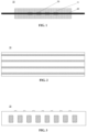
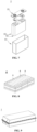
- the resistance layer 33 may be one or more parallel coatings disposed on the current collector 22 and being parallel to the longitudinal direction of the positive electrode sheet.
- the resistance layer 33 may also be a plurality of parallel coatings disposed on the current collector 22 and being perpendicular to the longitudinal direction of the positive electrode sheet.
- the resistance layer including the first positive electrode active material may play the role of increasing the energy density of the battery while increasing the polarization of the positive electrode sheet.
- the projection of at least a part of the positive electrode active material layer 11 on the current collector 22 does not overlap the projection of the resistance layer 33 on the current collector 22.
- the projection of a part of the positive electrode active material layer 11 on the current collector 22 overlaps the projection of the resistance layer 33 on the current collector 22.
- the projection of a part of the positive electrode active material layer 11 on the current collector 22 overlaps the projection of the resistance layer 33 on the current collector 22; and at the same time, a projection of another part of the positive electrode active material layer 11 on the current collector 22 does not overlap the projection of the resistance layer 33 on the current collector 22.
- the projection of the positive electrode active material layer 11 on the current collector 22 does not overlap at all the projection of the resistance layer 33 on the current collector 22.
- the mass content of the binder may be 10.0-85.0 wt% based on the total weight of the resistance layer.
- the mass content of the binder may be 10.0-80.0 wt%, 10.0-70.0 wt%, 15.0-85.0 wt%, 15.0-80.0 wt% or 15.0-70.0 wt% based on the total weight of the resistance layer.
- the mass content of the first positive electrode active material may be 10.0-70.0 wt% based on the total weight of the resistance layer.
- the mass content of the first positive electrode active material may be 10.0-65.0 wt%, 10.0-60.0 wt%, 15.0-70.0 wt%, 15.0-65.0 wt% or 15.0-60.0 wt% based on the total weight of the resistance layer.
- the mass content of the conductive agent may be 5.0-20.0 wt% based on the total weight of the resistance layer.
- the mass content of the conductive agent may be 5.0-15.0 wt%, 10.0-20.0 wt%, 10.0-15.0 wt% or 15.0-20.0 wt% based on the total weight of the resistance layer.
- the positive electrode active material layer may be a conventional positive electrode active material layer commonly used in the art. Therefore, the second positive electrode active material, the conductive agent and the binder in the positive electrode active material layer may all adopt conventional contents generally used in the art.
- the ratio R1/R2 of the film resistance value R1 of the positive electrode sheet in the part where the resistance layer is provided to the film resistance value R2 of the positive electrode sheet in the part of the coating region where the resistance layer is not provided may be set in a range of 1.15-26.00.
- the ratio R1/R2 is set within a specified range, so that the resistance difference between the positive electrode sheet in the part where the resistance layer is provided and the positive electrode sheet in the part of the coating region where the resistance layer is not provided is within a certain range.
- the ratio R1/R2 is adjusted within an appropriate range, it can also play a role in adjusting the amount of active lithium retained in the positive electrode active material layer above the resistance layer so as to flexibly adjust the service life of the battery.
- R1/R2 may be 1.15-20.00, 1.15-15.00, 1.15-10.00, 2.00-26.00, 2.00-20.00, 2.00-15.00, 2.00-10.00, 3.00-26.00, 3.00-20.00, 3.00-15.00 or 3.00-10.00.
- adjusting the ratio R1/R2 is mainly performed by adjusting the film resistance value R1 of the positive electrode sheet in the part where the resistance layer is provided.
- the positive electrode active material layer of the positive electrode sheet may be a conventional positive electrode active material layer commonly used in the art.
- the adjustment of R1 is mainly determined by adjusting the resistance of the resistance layer.
- R1 may be in a range of 0.3-8.0 S2.
- R1 may be 0.5-7.0 S2, 1.0-7.0 S2, 1.0-6.0 S2, 1.0-5.0 S2, 2.0-8.0 S2, 2.0-7.0 S2, 2.0-6.0 S2, 3.0-8.0 S2, 3.0-7.0 S2, 3.0-6.0 S2 or 3.0-5.0 ⁇ .
- R2 may be in a range of 0.3-4.0 ⁇ .
- R2 may be 0.3-3.5 S2, 0.3-2.0 S2, 0.3-1.0 S2, 0.3-0.5 S2, 0.2-3.5 S2, 0.2-2.0 S2, 0.2-1.0 S2 or 0.2-0.5 ⁇ .
- the first positive electrode active material included in the resistance layer and the second positive electrode active material included in the positive electrode active material layer may be the same or different.
- the first positive electrode active material and the second positive electrode active material may each include one or more selected from lithium cobalt oxide, lithium manganate, lithium nickel cobalt manganese oxide, lithium nickel cobalt aluminium oxide, lithium iron phosphate and lithium manganese nickel oxide.
- the first positive electrode active material and the second positive active material may each include one or more selected from LiNi 0.55 Co 0.05 Mn 0.4 O 2 , LiCoO 2 , LiNiO 2 , LiMnO 2 , LiMn 2 O 4 , LiNi 1/3 Co 1/3 Mn 1/3 O 2 (NCM333), LiNi 0.5 Co 0.2 Mn 0.3 O 2 (NCM523), LiNi 0.6 Co 0.2 Mn 0.2 O 2 (NCM622), LiNi 0.8 Co 0.1 Mn 0.1 O 2 (NCM811), LiNi 0.85 Co 0.15 Al 0.05 O 2 , LiFePO 4 (LFP) and LiMnPO 4 .
- LiNi 0.55 Co 0.05 Mn 0.4 O 2 LiCoO 2 , LiNiO 2 , LiMnO 2 , LiMn 2 O 4 , LiNi 1/3 Co 1/3 Mn 1/3 O 2 (NCM333), LiNi 0.5 Co 0.2 Mn 0.3 O 2 (NCM523), LiN
- the first positive electrode active material and the second positive electrode active material may each include one or more selected from a layered transition metal oxide, a polyanionic compound, a Prussian blue compound, sulfides, nitrides, carbides, and titanates.
- the first positive electrode active material and the second positive electrode active material may each include one or more selected from NaCrO 2 , Na 2 Fe 2 (SO 4 ) 3 , molybdenum disulfide, tungsten disulfide, vanadium disulfide, titanium disulfide, hexagonal boron nitride, carbon-doped hexagonal boron nitride, titanium carbide, tantalum carbide, molybdenum carbide, silicon carbide, Na 2 Ti 3 O 7 , Na 2 Ti 6 O 13 , Na 4 Ti 5 O 12 , Li 4 Ti 5 O 12 and NaTi 2 (PO 4 ) 3 .
- the conductive agent may include one or more selected from graphite, carbon black, acetylene black, graphene, and carbon nanotubes.
- the binder may include one or more selected from polyvinylidene fluoride, polyacrylic acid, polytetrafluoroethylene and polyimide.
- a compaction density of the positive electrode sheet may be 2.0-4.0 g/cm 3 , preferably 2.3-4.0 g/cm 3 . Setting the compaction density of the electrode sheet within the above range can not only reduce the thickness of the electrode sheet and increase the energy density of the battery, but also reduce an active lithium shuttle path and improve the charge and discharge rate and power.
- the compaction density of the positive electrode sheet may be 2.0-3.3 g/cm 3 , 2.0-3.5 g/cm 3 , 2.0-4.0 g/cm 3 , 2.2-3.3 g/cm 3 , 2.2-3.5 g/cm 3 , 3.0-4.0 g/cm 3 , 3.0-3.3 g/cm 3 or 2.2-3.5 g/cm 3 .
- a thickness of the current collector may be 8-14 ⁇ m, preferably 10-13 ⁇ m.
- the thickness of the current collector may be 8-13 ⁇ m, 9-14 ⁇ m, 9-13 ⁇ m or 10-14 ⁇ m.
- the thickness of the positive electrode sheet is 100-200 ⁇ m.
- the thickness of the positive electrode sheet may be 100-180 ⁇ m, 100-160 ⁇ m, 120-200 ⁇ m, 120-180 ⁇ m or 120-160 ⁇ m.
- the thickness of the resistance layer is 1-30 ⁇ m, preferably10-13 ⁇ m.
- the thickness of the resistance layer may be 1-25 ⁇ m, 1-20 ⁇ m, 4-30 ⁇ m, 4-25 ⁇ m, 4-20 ⁇ m, 7-30 ⁇ m, 7-25 ⁇ m, 7-20 ⁇ m, 10-30 ⁇ m, 10-25 ⁇ m or 10-20 ⁇ m.
- D v 50 of at least one of the first positive electrode active material and the second positive electrode active material is 1-20 ⁇ m. Setting the particle size of the positive electrode active material within the above range can further help the positive electrode sheet to retain an appropriate amount of active lithium. Specifically, when the particle size is large, the migration of lithium ions from the inside of particles to the outside of the particles will cause polarization.
- D v 50 of at least one of the first positive electrode active material and the second positive electrode active material may be 5-12 ⁇ m.
- D v 50 of at least one of the first positive electrode active material and the second positive electrode active material may be 1-18 ⁇ m, 1-15 ⁇ m, 2-20 ⁇ m, 2-18 ⁇ m, 2-15 ⁇ m, 3-20 ⁇ m or 3-18 ⁇ m.
- the current collector has two surfaces opposite in its own thickness direction.
- the coating region of the current collector may be provided on either or both of the two opposing surfaces of the positive electrode current collector.
- the positive electrode current collector may include metal foil or a composite current collector.
- the metal foil may include aluminum foil.
- the composite current collector may include a high molecular material substrate layer and a metal layer formed on at least one surface of the high molecular material substrate layer.
- the composite current collector may be formed by forming a metal material (aluminium, aluminium alloy, nickel, nickel alloy, titanium, titanium alloy, silver and silver alloy, etc.) on a high molecular material substrate (such as polypropylene (PP), polyethylene terephthalate (PET), polybutylene terephthalate (PBT), polystyrene (PS), and polyethylene (PE)).
- PP polypropylene
- PET polyethylene terephthalate
- PBT polybutylene terephthalate
- PS polystyrene
- PE polyethylene
- the resistance layer of the present application may be first formed on the current collector, and then the positive electrode active material layer may be formed on the current collector on which the resistance layer is formed.
- a method for forming the resistance layer of the present application on the current collector may include the following steps: mixing the conductive agent, the binder and the first positive electrode active material according to a certain mass ratio, adding, for example, into N-methylpyrrolidone (NMP), and stirring uniformly under the action of a vacuum stirrer to obtain slurry for the resistance layer with a certain solid content.
- NMP N-methylpyrrolidone
- a target region of the current collector is coated with the slurry for the resistance layer uniformly by a conventional coating method (for example, using an extrusion coater or a transfer coater), and is oven-dried at a suitable temperature (for example,85°C) to form the resistance layer of the present application on the current collector.
- a method for forming the positive electrode active material layer on the current collector on which the resistance layer is formed may include the following steps: mixing the second positive electrode active material, the conductive agent and the binder according to a certain mass ratio, adding, for example, into N-methylpyrrolidone (NMP), and stirring uniformly under the action of a vacuum stirrer to obtain slurry for the positive electrode active material layer with a certain solid content (e.g., 60 wt%).
- NMP N-methylpyrrolidone
- a target region of the current collector on which the resistance layer is formed is coated with the slurry for the positive electrode active material layer uniformly by a conventional coating method (for example, using an extrusion coater or a transfer coater), and is oven-dried at a suitable temperature (for example,85°C) to form the positive electrode active material layer on the current collector on which the resistance layer is formed.
- a conventional coating method for example, using an extrusion coater or a transfer coater
- the present application also provides a secondary battery, including a positive electrode, a negative electrode, an electrolyte and a separator, wherein the positive electrode includes the above-mentioned positive electrode sheet for the secondary battery of the present application.
- the present application further provides a battery module, including the secondary battery of the present application as described above.
- the present application further provides a battery pack, including the battery module of the present application as described above.
- the present application further provides an electrical apparatus, including the secondary battery of the present application as described above, or the battery module of the present application as described above, or the battery pack of the present application as described above, or a combination thereof.
- the deintercalated speed of active lithium ions in partial regions of the positive electrode sheet is slowed down, so that part of lithium is retained in the regions (because during charging, compared with a conventional positive electrode active material layer, the deintercalated speed of the active lithium ions in the regions is slower, part of the lithium can be retained at the end of charging).
- the lithium ions retained in the partial regions of the positive electrode sheet above are gradually released, and the battery capacity shows a trend of increasing first and then gradually decreasing, thereby slowing down the decay of the battery capacity and increasing the service life of the battery.
- a secondary battery is provided.
- the secondary battery includes a positive electrode sheet, a negative electrode sheet, an electrolyte, and a separator.
- active ions are intercalated and deintercalated back and forth between the positive electrode sheet and the negative electrode sheet.
- the electrolyte serves to conduct ions between the positive electrode sheet and the negative electrode sheet.
- the separator is provided between the positive electrode sheet and the negative electrode sheet, and mainly functions to prevent a short circuit between the positive electrode and the negative electrode while allowing ions to pass through.
- the negative electrode sheet includes a negative electrode current collector and a negative electrode active material layer arranged on at least one surface of the negative electrode current collector, and the negative electrode active material layer includes a negative electrode active material.
- the negative electrode active material commonly used for preparing a negative electrode of a secondary battery in the art can be used as the negative electrode active material.
- the negative electrode active material may be listed as follows: artificial graphite, natural graphite, soft carbon, hard carbon, silicon-based materials, tin-based materials, lithium titanate, and the like.
- the silicon-based material may be one or more selected from elemental silicon, a silicon oxide compound (e.g., silicon monoxide), a silicon-carbon composite, a silicon-nitrogen composite and silicon alloy.
- the tin-based material may be selected from one or more of elemental tin, a tin-oxygen compound and tin alloy.
- the negative electrode current collector has two surfaces opposite in its own thickness direction.
- the negative electrode active material layer may be arranged on either or both of the two opposite surfaces of the negative electrode current collector.
- the negative electrode current collector may include metal foil or a composite current collector.
- the metal foil may include copper foil.
- the composite current collector may include a high molecular material substrate layer and a metal layer formed on at least one surface of the high molecular material substrate layer.
- the composite current collector may be formed by forming a metal material (copper, copper alloy, nickel, nickel alloy, titanium, titanium alloy, silver and silver alloy, etc.) on a high molecular material substrate (such as polypropylene (PP), polyethylene terephthalate (PET), polybutylene terephthalate (PBT), polystyrene (PS), and polyethylene (PE)).
- PP polypropylene
- PET polyethylene terephthalate
- PBT polybutylene terephthalate
- PS polystyrene
- PE polyethylene
- the negative electrode active material layer usually includes a negative electrode active material, an optional binder, an optional conductive agent and other optional adjuvants, and is usually formed by coating and drying of slurry for the negative electrode active material layer.
- the slurry for the negative electrode active material layer is generally formed by dispersing the negative electrode active material as well as the optional conductive agent and the binder, etc. in a solvent and uniformly stirring.
- the solvent may be N-methyl pyrrolidone (NMP) or deionized water.
- the conductive agent may be one or more selected from superconducting carbon, acetylene black, carbon black, Ketjen black, carbon dot, carbon nanotube, graphene, and carbon nanofiber.
- the binder may be selected from one or more of styrene butadiene rubber (SBR), polyacrylic acid (PAA), sodium polyacrylate (PAAS), polyacrylamide (PAM), polyvinyl alcohol (PVA), sodium alginate (SA), polymethacrylic acid (PMAA) and carboxymethyl chitosan (CMCS).
- SBR styrene butadiene rubber
- PAA polyacrylic acid
- PAAS sodium polyacrylate
- PAM polyacrylamide
- PVA polyvinyl alcohol
- SA sodium alginate
- PMAA polymethacrylic acid
- CMCS carboxymethyl chitosan
- a thickener such as sodium carboxymethylcellulose (CMC-Na)
- CMC-Na sodium carboxymethylcellulose
- the positive electrode sheet, the negative electrode sheet, and the separator may be made into an electrode assembly by a winding process or a lamination process.
- the examples of the present application have no specific limitation on the type of the electrolyte, which can be selected according to requirements.
- the electrolyte can be solid or liquid.
- the electrolyte is liquid and typically includes an electrolyte salt and a solvent.
- the electrolyte salt may be one or more selected from lithium hexafluorophosphate (LiPF 6 ), lithium tetrafluoroborate (LiBF 4 ), lithium perchlorate (LiClO 4 ), lithium hexafluoroarsenate (LiAsF 6 ), lithium bis(fluorosulfonyl)imide (LiFSI), lithium bis(trifluoromethanesulfonyl)imide (LiTFSI), lithium trifluoromethanesulfonate (LiTFS), lithium difluoro(oxalato)borate (LiDFOB), lithium bis(oxalato)borate (LiBOB), lithium difluorophosphate (LiPO 2 F 2 ), lithium difluoro bis(oxalato)phosphate (LiDFOP) and lithium tetrafluoro(oxalato)phosphate (LiTFOP).
- LiPF 6 lithium hexafluoro
- the solvent may be one or more selected from fluoroethylene carbonate (FEC), ethylene carbonate (EC), propylene carbonate (PC), ethyl methyl carbonate (EMC), diethyl carbonate (DEC), dimethyl carbonate (DMC), dipropyl carbonate (DPC), methyl propyl carbonate (MPC), ethyl propyl carbonate (EPC), butylene carbonate (BC), methyl formate (MF), methyl acetate (MA), ethyl acetate (EA), propyl acetate (PA), methyl propionate (MP), ethyl propionate (EP), propyl propionate (PP), methyl butyrate (MB), ethyl butyrate (EB), 1,4-butyrolactone (GBL), sulfolane (SF), methylsulfonylmethane (MSM), ethyl methyl sulfone (EMS) and ethyl sul
- an additive is optionally included in the electrolyte.
- the electrolyte may include a negative electrode film-forming additive, a positive electrode film-forming additive, an additive for improving the overcharge performance of the battery, an additive for improving the high temperature performance of the battery, an additive for improving the low temperature performance of the battery, and the like.
- the separator separates the positive electrode sheet from the negative electrode sheet, preventing a short circuit in the battery, and enabling active ions to move between the positive and negative electrodes through the separator.
- the type of the separator is not particularly limited, and any well-known separator with a porous structure having good chemical stability and mechanical stability may be selected.
- a material of the separator may be one or more selected from a thin glass fiber film, a thin non-woven cloth film, a thin polyethylene (PE) film, a thin polypropylene (PP) film, a thin polyvinylidene fluoride film, and a multilayer composite thin film including one or more than two of the above.
- the separator may be a single-layer separator or a multi-layer composite separator, which is not particularly limited. When the separator is a multi-layer composite separator, the material of each layer may be the same or different, which is not particularly limited.
- the positive electrode sheet, the negative electrode sheet, and the separator may be made into an electrode assembly by a winding process or a lamination process.
- the secondary battery may include an outer package.
- the outer package may be used to encapsulate the above-mentioned electrode assembly and electrolyte solution.
- the outer package of the secondary battery may be a hard case, such as a hard plastic case, an aluminium case, a steel case, and the like.
- the outer package of the secondary battery can also be a soft pack, such as a bag-type soft pack.
- the material of the soft package may be plastic, and examples of the plastic include polypropylene (PP), polybutylene terephthalate (PBT), polybutylene succinate (PBS), and the like.
- the shape of the secondary battery is not particularly limited in the present application, and it may be cylindrical, square, or any other shape.
- Fig. 6 is an example of a secondary battery 5 having a square structure.
- the outer package may include a case 51 and a cover plate 53.
- the case 51 may include a bottom plate and a side plate connected to the bottom plate, with the bottom plate and the side plate enclosing to form an accommodating cavity.
- the case 51 has an opening in communication with the accommodating cavity, and the cover plate 53 may cover the opening to close the accommodating cavity.
- the positive electrode sheet, the negative electrode sheet, and the separator may be formed into an electrode assembly 52 by a winding process or a lamination process.
- the electrode assembly 52 is encapsulated in the accommodating cavity.
- the electrolyte solution impregnates the electrode assembly 52.
- the number of electrode assemblies 52 included in the secondary battery 5 may be one or more, which can be selected by those skilled in the art according to specific actual requirements.
- the secondary batteries may be assembled into a battery module, and the number of the secondary batteries included in the battery module may be one or more, and the specific number may be selected by those skilled in the art according to the application and capacity of the battery module.
- Fig. 8 is an example of a battery module 4.
- a plurality of secondary batteries 5 may be sequentially arranged along the length direction of the battery module 4.
- any other arrangement of the plurality of secondary batteries 5 is also possible.
- the plurality of secondary batteries 5 may be fixed by fasteners.
- the battery module 4 may further include a case having an accommodating space, in which the plurality of secondary batteries 5 are accommodated.
- the above-mentioned battery modules may further be assembled into a battery pack.
- the number of the battery modules contained in the battery pack may be selected by those skilled in the art according to the use of the battery pack.
- Figs. 9 and 10 are an example of a battery pack 1.
- the battery pack 1 may include a battery box and a plurality of battery modules 4 arranged in the battery box.
- the battery box includes an upper box 2 and a lower box 3, wherein the upper box 2 may cover the lower box 3 and forms an enclosed space for accommodating the battery modules 4.
- the plurality of battery modules 4 may be arranged in the battery box in any manner.
- the present application further provides an electrical apparatus, and the electrical apparatus includes one or more of the secondary battery, the battery module, or the battery pack provided by the present application.
- the secondary battery, battery module, or battery pack may be used as a power source for the electrical apparatus, and may also be used as an energy storage unit for the electrical apparatus.
- the electrical apparatus may be, but is not limited to, a mobile device (such as a mobile phone and a laptop), an electric vehicle (such as an all-electric vehicle, a hybrid electric vehicle, a plug-in hybrid electric vehicle, an electric bicycle, an electric scooter, an electric golf cart, and an electric truck), an electric train, a ship, a satellite, an energy storage system, etc.
- the secondary battery, battery module, or battery pack can be selected according to its use requirements.
- Fig. 11 is an example of an electrical apparatus.
- the apparatus is an all-electric vehicle, a hybrid electric vehicle, a plug-in hybrid electric vehicle, or the like.
- a battery pack or a battery module may be used.
- the electrical apparatus may be a mobile phone, a tablet, a laptop, etc.
- the apparatus is generally required to be light and thin, and may use a secondary battery as a power source.
- a conductive agent Super P, a binder polyvinylidene fluoride (PVDF) and a positive electrode active material LiNi 0.55 Co 0.05 Mn 0.4 O 2 were mixed in a certain mass ratio.
- An obtained mixture was added to a solvent N-methylpyrrolidone (NMP), and stirred uniformly under the action of a lithium-ion battery slurry mixer (Shanghai Baomian Electromechanical Equipment Co., Ltd., Model BMXJ5-2000L) to obtain slurry for a resistance layer.
- NMP solvent N-methylpyrrolidone
- a positive electrode active material LiNi 0.55 Co 0.05 Mn 0.4 O 2 , a conductive agent Super P and a binder polyvinylidene fluoride (PVDF) were mixed in a mass ratio of 96:2.5:1.5, and a solvent N-methylpyrrolidone (NMP) was added and stirred uniformly in a vacuum stirrer to obtain slurry for a positive electrode active material layer.
- the solid content in the slurry was 60 wt%.
- a target region of a current collector was uniformly coated with the slurry for the resistance layer prepared as described above by an extrusion coater.
- a lithium battery slot extrusion coater (Guangdong Hongbao Technology Co., Ltd., HB-TBY750) was used to coat aluminum foil with a thickness of 8-14 ⁇ m uniformly with the slurry for the positive electrode active material layer prepared as described above at a coating speed of 36 m/min, with the coating weight being 0.9 mg/cm 2 , wherein the length of a slurry nozzle of an extrusion nozzle of the extrusion coater was controlled by controlling a coating spacer with a specific-width opening, and then a width-controlled undercoat layer arranged along the longitudinal length of the aluminum foil can be obtained.
- the obtained positive electrode current collector aluminum foil with the undercoat layer was oven-dried at 85°C, thereby forming a resistance layer with a thickness of 1-30 ⁇ m on the positive electrode current collector aluminum foil.
- a target region of the positive electrode current collector aluminum foil on which the resistance layer was formed is uniformly coated with the slurry for the positive electrode active material layer prepared as described above.
- Coating of the slurry for the positive electrode active material layer may be performed by the same method as the coating method of the slurry for the resistance layer described above.
- a transfer coater may also be used for coating.
- a transfer coater (Yakang Precision Machinery Co., Ltd., DT600/750) was used to uniformly coat the target region of the current collector on which the resistance layer of the present application was formed with the slurry for the positive electrode active material layer by using a process conventional in the art, and then the current collector was oven-dried at 85°C to form a positive electrode active material layer on the current collector aluminum foil on which the resistance layer was formed.
- a Dv50 value of the positive electrode active material refers to the median particle size of the positive electrode active material. Specifically, a specific Dv50 value indicates that the diameter of particles accounting for 50% of the total volume is larger than the value, and the diameter of particles accounting for 50% of the total volume is smaller than the value.
- the Dv50 value of the positive electrode active material may be measured with reference to a method specified in GB/T19077-2016 . More specifically, the Dv50 value may be measured according to a following method.
- Sample pretreatment a clean beaker was taken, an appropriate amount of a sample to be tested was added, a surfactant sodium dodecyl sulfate was added dropwise, then deionized water was added as a dispersant, and ultrasonic treatment (120 W/5 min) was performed to ensure that the sample was completely dispersed in the dispersant.
- Test an LS-909 laser particle size analyzer (Omega) was used to measure Dv50. After the sample was poured into an injection tower, the sample was circulated to a test optical path system with a solution, scattered light emitted by particles under the irradiation of a laser beam was received, and the energy distribution thereof is measured, so a particle size distribution feature of the particles can be obtained (shading degree: 8-12%), and the Dv50 value of the material was finally obtained.
- the film resistance value of the positive electrode sheet in the part provided with the resistance layer and the film resistance value of the positive electrode sheet in the part of the coating region without the resistance layer were both measured using a conventional electrode sheet resistance meter (Initial Energy Science & Technology, ZEST BER1000). Specifically, a square detection sample with a size of 10 cm ⁇ 10 cm was cut from the to-be-measured part of the positive electrode sheet. At a measurement site, upper and lower sides of the detected sample were clamped between two conductive terminals of the resistance meter, a certain pressure was applied for fixation, and the resistance R of the detected sample was tested.
- a conventional electrode sheet resistance meter Initial Energy Science & Technology, ZEST BER1000
- the diameter of the conductive terminals of the resistance meter was 14 mm, the pressure applied during the measurement was 5 MPa to 27 MPa, and a sampling time range was 5 s to 17 s.
- R is the resistance value of the sample read by the resistance meter.
- the film resistance value measured at the part where the resistance layer is provided is denoted as R1.
- the film resistance value measured at the part of the coating region where the resistance layer is not provided is denoted as R2.
- a negative electrode active material artificial graphite, a conductive agent Super P, a thickener sodium carboxymethyl cellulose (CMC) and a binder styrene butadiene rubber emulsion (SBR) were mixed at a mass ratio of 97:0.7:1.8:0.5, and added into deionized water and stirred uniformly under the action of a vacuum stirrer to obtain negative electrode slurry.
- the solid content in the negative electrode slurry was 56 wt%.
- negative electrode current collector copper foil was uniformly coated with the negative electrode slurry by an extrusion coater or a transfer coater, oven-dried at 85°C, and then subjected to cold pressing, trimming, cutting and slitting to obtain a negative electrode sheet.
- LiPF 6 lithium salt
- EMC ethylene carbonate
- DEC diethyl carbonate
- VC additive vinylene carbonate
- a polyethylene film (PE) with a thickness of 7 ⁇ m was used as a base film of a separator, and alumina, sodium carboxymethyl cellulose (CMC) and acrylate with the weight ratio of 93%:3%:4% were added into deionized water and stirred uniformly under the action of a vacuum stirrer to obtain slurry, wherein the solid content in the slurry was 55 wt%.
- the obtained slurry was uniformly sprayed on both surfaces of the base film with a thickness of 2 ⁇ m on one side to obtain a separator.
- the positive electrode sheet, the separator and the negative electrode sheet were stacked in sequence, so that the separator was positioned between the positive electrode sheet and the negative electrode sheet to serve for isolation. Then, obtained laminate was wound into a square bare cell, tabs were welded, the bare cell was put into a square aluminum case, and a top cover was laser welded. Then, after vacuum baking at 80°C to remove water, the electrolyte solution was injected and sealed.
- a finished hard-shell lithium-ion battery was obtained with a thickness of 28 mm, a width of 97.5 mm, and a length of 148 mm.
- the cycle performance of a battery including the positive electrode sheet of the present application was evaluated under the condition of 0.5C/0.5C at a temperature of 25°C.
- the cell was placed in a Nebula battery charge-discharge test system (model BAT-NEEFLCT-05300-V012), and charged with a constant current and a constant voltage at a rate of 0.5C to a charging cut-off voltage of 4.4 V, the cell was discharged with a constant current at a rate of 0.5C to a discharge cut-off voltage of 2.5 V after standing for 5 minutes, the discharge capacity was recorded, and then standing was performed for 5 minutes, and so on. The number of cycles in which the discharge capacity remained above 80% of the initial capacity was recorded.
- the power performance of the battery can be determined. Specifically, the cell was placed in the Nebula battery charge-discharge test system at 25°C, charged with a constant current and a constant voltage at a rate of 0.5C to a charge cut-off voltage of 4.4 V, and discharged at specific power after standing for 5 minutes to ensure that discharge is stopped when the voltage of the battery just reached 2.5 V at 60 s, and the power at this time is the 60s pulse discharge power.
- the positive electrode sheet and the battery were prepared according to the general method described above.
- the thickness of the aluminum foil as the current collector was 12 ⁇ m.
- the thickness of the resistance layer provided on the current collector was 10 ⁇ m.
- the Dv50 of the positive electrode active material in the positive electrode active material layer was 4 ⁇ m.
- the thickness of the positive electrode sheet was 180 ⁇ m, and the compaction density was 3.4 g/cm 3 .
- a projection of a part of the positive electrode active material layer on the current collector overlapped a projection of the resistance layer on the current collector, as shown in Fig. 4 .
- composition of the resistance layer in the positive electrode sheet, the area ratio S of the resistance layer relative to the coating region of the current collector, the film resistance value R1 of the part provided with the resistance layer, the film resistance value R2 of the part without the resistance layer, a corresponding value of R1/R2, a value of the polarization parameter P and the number of cycles and 60s pulse discharge power of the battery measured by the performance test method described above are shown in Table 1 below.
- the resistance layer of the present invention is not provided on the current collector. Therefore, the positive electrode sheet only includes the current collector and the positive electrode active material layer. Performance test results of the control example are also shown in Table 1 below. Table 1 Exampl e 1 Exampl e 2 Exampl e3 Exampl e 4 Exampl e 5 Exam ple 6 Compa rative Exampl e 1 Compa rative Exampl e 2 Control Exampl e Resist ance layer Comp ositio n Binder Mass content 80% 70% 50% 30% 20% 85% 99% 95% Not provide d with Resista nce layer Conduct!
- the resistance layer includes a certain mass content of positive electrode active material, which can increase the polarization of the positive electrode sheet while improving the energy density of the battery, thereby ensuring that the battery has good power performance.
- the 60s pulse discharge power of the battery is maintained at 950 W or more.
- the active lithium retained in the region is gradually released, and the battery capacity shows a trend of increasing first and then gradually decreasing, thereby slowing down the decay of the battery capacity and increasing the service life of the battery.
- the composition of the resistance layer specifically by adjusting the respective mass contents of the binder, the conductive agent and the positive electrode active material in the resistance layer to adjust the resistance value of the resistance layer, it is possible to adjust the positive electrode active material layer above the resistance layer. Therefore, the amount of active lithium retained in the positive electrode sheet can be adjusted, and the service life of the battery can be adjusted according to needs.
- the positive electrode sheet and the battery were prepared according to the general method described above.
- the thickness of the aluminum foil as the current collector was 12 ⁇ m.
- the thickness of the resistance layer provided on the current collector was 10 ⁇ m.
- the Dv50 of the positive electrode active material in the positive electrode active material layer was 4 ⁇ m.
- the thickness of the positive electrode sheet was 180 ⁇ m, and the compaction density was 3.4 g/cm 3 .
- a projection of the positive electrode active material layer on the current collector did not overlap a projection of the resistance layer on the current collector at all, as shown in Fig. 5 .
- composition of the resistance layer in the positive electrode sheet, the area ratio S of the resistance layer relative to the coating region of the current collector, the film resistance value R1 of the part provided with the resistance layer, the film resistance value R2 of the part without the resistance layer, a corresponding value of R1/R2, a value of the polarization parameter P and the number of cycles and 60s pulse discharge power of the battery measured by the performance test method described above are shown in Table 2 below.
- the resistance layer includes a certain mass content of positive electrode active material, which can increase the polarization of the positive electrode sheet while improving the energy density of the battery, thereby ensuring that the battery has good power performance.
- the 60s pulse discharge power of the battery is maintained at 1000 W or more.
- the composition of the resistance layer specifically by adjusting the respective mass contents of the binder, the conductive agent and the positive electrode active material in the resistance layer to adjust the resistance value of the resistance layer, it is possible to adjust the positive electrode active material layer above the resistance layer. Therefore, the amount of active lithium retained in the positive electrode sheet can be adjusted, and the service life of the battery can be adjusted according to needs.
- the positive electrode sheet and the battery were prepared according to the general method described above.
- the mass content of the conductive agent is 10%
- the mass content of the binder is 30%
- the mass content of the positive electrode active material is 60%.
- the thickness of the aluminum foil as the current collector was 12 ⁇ m.
- the thickness of the resistance layer provided on the current collector was 10 ⁇ m.
- the Dv50 of the positive electrode active material in the positive electrode active material layer was 4 ⁇ m.
- the thickness of the positive electrode sheet was 180 ⁇ m, and the compaction density was 3.4 g/cm 3 .
- the film resistance value R1 of the part provided with the resistance layer and the film resistance value R2 of the part not provided with the resistance layer were 1.16 S2 and 0.35 ⁇ respectively.
- R1/R2 3.31.
- a projection of a part of the positive electrode active material layer on the current collector overlapped a projection of the resistance layer on the current collector, as shown in Fig. 4 .
- Table 3 The area ratio S of the resistance layer relative to the coating region of the current collector, the corresponding polarization parameter P value, and the number of cycles and 60s pulse discharge power of the battery measured by the performance test method described above are shown in Table 3 below.
- Table 3 S P Number of cycles 60s pulse discharge power (W)
- Example 11 0.15 18.8 1230 1542.3
- Example 12 0.20 13.2 1932 1477.4
- Example 13 0.30 7.7 2298 1427.3
- Example 14 0.40 5.0 2509 1381.1
- Example 15 0.50 3.3 2388 1298.6
- Example 16 0.60 2.2 2176 1212.9
- Example 17 0.70 1.4 1870 1077.0
- the resistance layer includes a certain mass content of positive electrode active material, which can increase the polarization of the positive electrode sheet while improving the energy density of the battery, thereby ensuring that the battery has good power performance.
- the 60s pulse discharge power of the battery is maintained at 950 W or more.
- the ratio of the film resistance value R1 of the part where the resistance layer is provided to the film resistance value R2 of the part where the resistance layer is not provided is 3.31.
- an appropriate amount of active lithium may be retained for the positive electrode sheet, thereby increasing the service life of the battery and ensuring the power performance of the battery.
- Adjusting the area ratio S of the resistance layer relative to the coating region of the current collector may also play a role in adjusting the amount of lithium retained in the positive electrode active material layer above the resistance layer, thereby adjusting the amount of active lithium retained in the positive electrode sheet, and the service life of the battery can be adjusted according to needs.
- the film resistance of the positive electrode sheet in the part provided with the resistance layer is adjusted to be appropriately larger than the film resistance of the part without the resistance layer, and/or by adjusting the area ratio of the resistance layer relative to the coating region of the current collector, appropriate lithium ion polarization can be generated in the positive electrode sheet, thereby achieving the polarization parameter P in the range of 0.4-65.0.
- the positive electrode sheet and the battery were prepared according to the general method described above.
- the mass content of the conductive agent is 5%
- the mass content of the binder is 25%
- the mass content of the positive electrode active material is 70%.
- the thickness of the aluminum foil as the current collector was 12 ⁇ m.
- the thickness of the resistance layer provided on the current collector was 10 ⁇ m.
- the Dv50 of the positive electrode active material in the positive electrode active material layer was 4 ⁇ m.
- the film resistance value R1 of the part provided with the resistance layer and the film resistance value R2 of the part not provided with the resistance layer were 0.92 S2 and 0.35 ⁇ respectively.
- the area ratio of the resistance layer relative to the coating region of the current collector was 0.30. Accordingly, the value of the polarization parameter P was 6.1.
- a projection of the positive electrode active material layer on the current collector did not overlap a projection of the resistance layer on the current collector at all, as shown in Fig. 5 .
- the thickness of the electrode sheet is reduced, the cycle life of the battery is increased, and the active lithium shuttle path is reduced, thereby further improving the power performance of the battery while increasing the cycle life of the battery, the number of cycles in which the discharge capacity is maintained at more than 80% of the initial capacity reaches 1950 times or more, and the 60s pulse discharge power is maintained at 1200 W or more.
- the positive electrode sheet and the battery were prepared according to the general method described above.
- the mass content of the conductive agent is 10%
- the mass content of the binder is 80%
- the mass content of the positive electrode active material is 10%.
- the thickness of the aluminum foil as the current collector was 12 ⁇ m.
- the thickness of the resistance layer provided on the current collector was 10 ⁇ m.
- the Dv50 of the positive electrode active material in the positive electrode active material layer was 4 ⁇ m.
- the thickness of the positive electrode sheet was 180 ⁇ m, and the compaction density was 3.4 g/cm 3 .
- the film resistance value R1 of the part provided with the resistance layer and the film resistance value R2 of the part not provided with the resistance layer were 2.43 S2 and 0.35 ⁇ respectively.
- the area ratio of the resistance layer relative to the coating region of the current collector was 0.55. Accordingly, the value of the polarization parameter P was 5.7.
- Example 5 Dv50 of the positive electrode active material used in the positive electrode active material layer, as well as the number of cycles and 60s pulse discharge power of the battery measured by the performance test method described above are shown in Table 5 below.
- Table 5 Positive electrode active material Dv50 ( ⁇ m) Number of cycles 60s pulse discharge power (W)
- Example 24 3 1845 1540.2
- Example 25 4 1971 1491.4
- Example 26 5 2110 1474.5
- Example 27 6 2211 1436.8
- Example 30 10 2154 1314.3
- Example 32 13 1959 1244.0
- Example 33 14 1866 1230.5
- Dv50 of the positive electrode active material is in the preferred range of 5-12 ⁇ m
- the interior of the particles is polarized, and the particles are more fully dispersed, so that the power performance of the battery is fully ensured while the cycle life of the battery is further increased
- the number of cycles in which the discharge capacity is maintained at more than 80% of the initial capacity reaches more than 2000 times
- 60s pulse discharge power is maintained at 1300 W or more.
- the film resistance of the positive electrode sheet in the part provided with the resistance layer is adjusted to be appropriately larger than the film resistance of the part without the resistance layer, and/or by adjusting the area ratio of the resistance layer relative to the coating region of the current collector, appropriate lithium ion polarization can be generated in the positive electrode sheet, thereby achieving the polarization parameter P in the range of 0.4-65.0, and giving the positive electrode sheet appropriate polarizability, and thus capacity decay of the battery is lowered, the number of cycles in which the discharge capacity is maintained at more than 80% of the initial capacity reaches more than 1100 times, the service life of the battery is greatly prolonged, good power performance of the battery is ensured at the same time, and 60s pulse discharge power of the battery is kept at 950 W or more.
- a positive electrode sheet provided with a resistance layer on a current collector of the present application has the effect of increasing lithium ion polarization of the electrode sheet, and in the cycle process, with the gradual aging and elimination of the battery polarization, the battery capacity shows a trend of rising first and then gradually decaying, which increases the cycle life of the battery while ensuring the power performance of the battery.
- the present application is suitable for industrial applications.
Landscapes
- Chemical & Material Sciences (AREA)
- Chemical Kinetics & Catalysis (AREA)
- Electrochemistry (AREA)
- General Chemical & Material Sciences (AREA)
- Engineering & Computer Science (AREA)
- Inorganic Chemistry (AREA)
- Manufacturing & Machinery (AREA)
- Materials Engineering (AREA)
- Battery Electrode And Active Subsutance (AREA)
- Secondary Cells (AREA)
Abstract
Description
- The present application relates to the technical field of secondary batteries, and in particular to a positive electrode sheet applicable to a secondary battery, as well as a secondary battery including the same, a battery module, a battery pack, and an electrical apparatus.
- In recent years, with the vigorous promotion of new energy electric vehicles, its market share is also increasing. At present, the most widely used energy storage batteries for new energy electric vehicles are mainly lithium-ion secondary batteries. With the continuous development of lithium-ion secondary batteries and their widening applications, higher requirements have been placed on their energy density, cycle performance and safety performance.
- However, at present, the cycle life of lithium-ion secondary batteries is generally 800 to 900 times of charge and discharge, and then the capacity decays to about 80% of the initial value. At present, in order to increase the service life of a battery, more effective means are: improving the surface coating of active materials, and reducing surface side reactions; and increasing the content of conductive materials, and lowering the resistance. However, the existing means all bring high costs and technical challenges. Therefore, the existing lithium-ion secondary batteries still need to be improved in terms of service life.
- In view of the above problems, the object of the present application is to provide a positive electrode sheet for a secondary battery and a secondary battery including the positive electrode sheet, a battery module, a battery pack and an electrical apparatus, wherein by controlling the release of lithium ions, it is realized that the capacity decay of the battery is slowed down while ensuring the power performance of the battery, thereby extending the service life.
- In order to implement the above object, in one aspect, the present application provides a positive electrode sheet for a secondary battery, including a current collector, a resistance layer and a positive electrode active material layer, wherein the current collector includes a coating region and a non-coating region other than the coating region, the resistance layer includes a conductive agent, a binder and a first positive electrode active material, the positive electrode active material layer includes a second positive electrode active material, a conductive agent and a binder, a resistance of the resistance layer is greater than a resistance of the positive electrode active material layer, and the resistance layer is provided on the current collector. In a cross section of the positive electrode sheet, a projection of at least a part of the positive electrode active material layer on the current collector (in the present application, the projection refers to an orthographic projection perpendicular to a main surface of the current collector) and a projection of the resistance layer on the current collector do not overlap, and a polarization parameter P of the positive electrode sheet is in a range of 0.4-65.0, the polarization parameter P=((1-S)/S)•(R1/R2), wherein S is an area ratio of the resistance layer relative to the coating region of the current collector, R1 is a film resistance value of the positive electrode sheet in a part where the resistance layer is provided, and R2 is a film resistance value of the positive electrode sheet in a part of the coating region where the resistance layer is not provided.
- In some embodiments, P is preferably in a range of 0.5-36.0, more preferably in a range of 1.5-8.0.
- In some embodiments, S is preferably in a range of 0.15-0.85, more preferably in a range of 0.20-0.80, more preferably in a range of 0.40-0.60.
- In some embodiments, a projection of a part of the positive electrode active material layer on the current collector overlaps the projection of the resistance layer on the current collector.
- In some embodiments, the projection of the positive electrode active material layer on the current collector and the projection of the resistance layer on the current collector do not overlap at all.
- In some embodiments, in the resistance layer, the mass content of the binder is 10.0-85.0 wt% based on the total weight of the resistance layer; optionally, the mass content of the first positive electrode active material is 10.0-70.0 wt% based on the total weight of the resistance layer; and optionally, the mass content of the conductive agent is 5.0-20.0 wt% based on the total weight of the resistance layer.
- In some embodiments, R1/R2 is in a range of 1.15-26.00; preferably, R1 is in a range of 0.3-8.0 Ω; and/or preferably, R2 is in a range of 0.3-4.0 S2.
- In some embodiments, the first positive electrode active material and the second positive electrode active material each include one or more selected from lithium cobalt oxide, lithium manganate, lithium nickel cobalt manganese oxide, lithium nickel cobalt aluminium oxide, lithium iron phosphate, and lithium manganese nickel oxide; the conductive agent includes one or more selected from graphite, carbon black, acetylene black, graphene and carbon nanotubes; and the binder includes one or more selected from polyvinylidene fluoride, polyacrylic acid, polytetrafluoroethylene and polyimide.
- In other embodiments, the first positive electrode active material and the second positive electrode active material each include one or more selected from layered transition metal oxide, polyanionic compound, Prussian blue compound, sulfide, nitride, carbide and titanate; the conductive agent includes one or more selected from graphite, carbon black, acetylene black, graphene and carbon nanotubes; and the binder includes one or more selected from polyvinylidene fluoride, polyacrylic acid, polytetrafluoroethylene and polyimide.
- In some embodiments, a compaction density of the positive electrode sheet is 2.0-4.0 g/cm3, preferably 2.3-4.0 g/cm3.
- In some embodiments, a thickness of the current collector is 8-14 µm, preferably 10-13 µm; a thickness of the positive electrode sheet is 100-200 µm; and/or a thickness of the resistance layer is 1-30 µm, preferably 10-13 µm.
- In some embodiments, Dv50 of at least one of the first positive electrode active material and the second positive electrode active material is 1-20 µm, preferably 5-12 µm.
- In another aspect, the present application also provides a secondary battery, including a positive electrode, a negative electrode, an electrolyte and a separator, wherein the positive electrode may include the above-mentioned positive electrode sheet for the secondary battery of the present application.
- In another aspect, the present application further provides a battery module. The battery module of the present application may include the secondary battery of the present application as described above.
- In another aspect, the present application further provides a battery pack. The battery pack of the present application may include the battery module of the present application as described above.
- In another aspect, the present application further provides an electrical apparatus. The electrical apparatus of the present application may include the secondary battery of the present application as described above, or the battery module of the present application as described above, or the battery pack of the present application as described above, or a combination thereof.
- In the secondary battery of the present application, by applying the positive electrode sheet provided with the resistance layer of the present application to the battery, the deintercalated speed of active lithium ions in partial regions of the positive electrode sheet is slowed down, so that part of lithium is retained in the regions (because during charging, compared with a conventional positive electrode active material layer, the deintercalated speed of the active lithium ions in the regions is slower, part of the lithium can be retained at the end of charging). During the subsequent cycle of the battery, with the gradual aging of the battery, the active lithium retained in the partial regions of the positive electrode sheet above is gradually released, and the battery capacity shows a trend of increasing first and then gradually decreasing, thereby increasing the service life of the battery.
-
-
Fig. 1 is a schematic cross-sectional view of a positive electrode sheet in a thickness direction of one embodiment of the present application. -
Fig. 2 is a schematic top view of the positive electrode sheet of the embodiment of the present application shown inFig. 1 . -
Fig. 3 is a schematic top view of a positive electrode sheet of one embodiment of the present application. -
Fig. 4 is a schematic cross-sectional view of a positive electrode sheet in a thickness direction of one embodiment of the present application. -
Fig. 5 is a schematic cross-sectional view of a positive electrode sheet in a thickness direction of one embodiment of the present application. -
Fig. 6 is a schematic diagram of a secondary battery of one embodiment of the present application. -
Fig. 7 is an exploded diagram of the secondary battery of the embodiment of the present application shown inFig. 6 . -
Fig. 8 is a schematic diagram of a battery module of one embodiment of the present application. -
Fig. 9 is a schematic diagram of a battery pack of one embodiment of the present application. -
Fig. 10 is an exploded diagram of the battery pack of the embodiment of the present application shown inFig. 9 . -
Fig. 11 is a schematic diagram of an electrical apparatus in which a secondary battery is used as a power source of one embodiment of the present application. -
Fig. 12 is a graph of cycle performance of a secondary battery obtained in example 7. -
- 10 Positive electrode sheet
- 11 Positive electrode active material layer
- 22 Current collector
- 33 Resistance layer
- 1 Battery pack
- 2 Upper box
- 3 Lower box
- 4 Battery module
- 5 Secondary battery
- 51 Case
- 52 Electrode assembly
- 53 Top cover assembly
- In order to make the objectives, technical solutions and advantages of the present application clearer, the embodiments of the present application will be described in detail below with reference to the drawings. However, it should be understood by those of ordinary skills in the art that these embodiments are only used for illustrating the technical solutions of the present application, rather than limiting them.
- For the sake of brevity, the present application specifically discloses some numerical ranges. However, any lower limit can be combined with any upper limit to form a range not explicitly recited; and any lower limit can be combined with another lower limit to form a range not explicitly recited, and likewise, any upper limit can be combined with any another upper limit to form a range not explicitly recited. Further, each individually disclosed point or single value itself may serve as a lower limit or upper limit in combination with any other point or single value or with other lower limits or upper limits to form an unspecified range.
- Unless otherwise specified, all embodiments and optional embodiments of the present application may be combined with each other to form new technical solutions.
- Unless otherwise specified, all technical features and optional technical features of the present application may be combined with each other to form new technical solutions.
- Unless otherwise specified, all steps of the present application may be performed sequentially or randomly, and preferably sequentially. For example, the method comprises steps (a) and (b), meaning that the method may comprise steps (a) and (b) performed sequentially, or may comprise steps (b) and (a) performed sequentially. For example, the reference to the method may further comprise step (c), meaning that step (c) may be added to the method in any order, for example, the method may comprise steps (a), (b) and (c), or may comprise steps (a), (c) and (b), or may comprise steps (c), (a) and (b), and so on.
- Unless otherwise specified, the terms "comprise", "comprising", "include" and "including" mentioned in the present application may be open-ended or closed-ended. For example, the "including" and "comprising" may indicate that it is possible to include or comprise other components not listed, and it is also possible to include or comprise only the listed components.
- Unless otherwise specified, in the present application, terms "center", "longitudinal", "transverse", "length", "width", "thickness", "upper," "lower," "front," "back," "left," "right," "vertical," "horizontal," "top," "bottom," "inner," "outer," "clockwise," "counterclockwise," "transverse," "longitudinal," "axial", "radial", "circumferential", etc. indicating orientation or position relationships refer to being based on the orientation or position relationships shown in the drawings and are only intended to facilitate the simplified description of the embodiments of the present application, rather than indicating or implying that the apparatus or element referred to must have a particular orientation or position relationship or be constructed and operated in a particular orientation or position relationship, and therefore are not to be interpreted as limitations on the embodiments of the present application.
- In the prior art, it is generally recognized that reducing the impedance of an electrode sheet including an active material layer and a current collector can reduce the internal resistance of a cell and help improving the cycle performance of a lithium-ion secondary battery. The kinetic performance of a battery is affected by the deintercalated speed of lithium ions of a positive electrode sheet, and the higher the deintercalated speed of the lithium ions, i.e., the higher the speed of moving of the lithium ions deintercalated from a positive electrode active material layer to a negative electrode, the better the kinetic performance.
- However, the inventors of the present application have surprisingly found that by providing a resistance layer having higher resistance than the positive electrode active material layer in a predetermined manner on the current collector of the positive electrode sheet for the secondary battery, it is possible to improve the cycle performance of the secondary battery and prolong the service life of the battery instead. Specifically, the projection of the resistance layer of the present application on the current collector does not overlap the projection of at least a part of the positive electrode active material layer on the current collector. Thus, when the battery starts to be charged, the potential of the positive electrode sheet is equal everywhere, and the lithium ions are deintercalated from the positive electrode active material layer and move toward a negative electrode. In the charging process, due to the existence of the resistance layer, the positive electrode active material layer above the resistance layer (the projections overlapped) or the resistance layer itself retains a part of lithium (that is, a part of lithium is not deintercalated from the positive electrode active material and is retained), and the positive electrode active material layer not above the resistance layer (the projections not overlapped) is not affected by the above. As the lithium-ion secondary battery is charged and discharged, the lithium retained in the positive electrode active material layer above the resistance layer continuously replenishes lithium consumed by the negative electrode. In the cycle process, with the gradual elimination and aging of the battery polarization, the battery capacity presents the trend of rising first and then gradually decaying, which will eventually reduce the capacity decay of the battery as a whole and prolong the service life of the battery.
- Based on the above findings, the present application provides a positive electrode sheet for a secondary battery, including: a current collector, a resistance layer, and a positive electrode active material layer, wherein
- the current collector includes a coating region and a non-coating region other than the coating region,
- the resistance layer includes a conductive agent, a binder and a first positive electrode active material,
- the positive electrode active material layer includes a second positive electrode active material, a conductive agent and a binder,
- a resistance of the resistance layer is greater than a resistance of the positive electrode active material layer, and the resistance layer is disposed on the current collector,
- in a cross section of the positive electrode sheet (in the present application, the cross section refers to a section perpendicular to a main surface of the current collector), a projection of at least a part of the positive electrode active material layer on the current collector and a projection of the resistance layer on the current collector do not overlap, and
- a polarization parameter P of the positive electrode sheet is in a range of 0.4-65.0, and the polarization parameter P=((1-S)/S)•(R1/R2), wherein S is an area ratio of the resistance layer relative to the coating region of the current collector, R1 is a film resistance value of the positive electrode sheet in a part where the resistance layer is provided, and R2 is a film resistance value of the positive electrode sheet in a part of the coating region where the resistance layer is not provided.
- As mentioned above, in the present application, the current collector includes the coating region and optionally the non-coating region other than the coating region. In the coating region, the positive electrode active material layer and the resistance layer may be provided on the current collector. The non-coating region other than the coating region may be located at two ends or the periphery of the coating region. In the present application, the purpose of describing the non-coating region is only to illustrate that the area as a basis for the area ratio of the resistance layer is the area of a region of the current collector coated with a coating (rather than the area of the entire current collector). In other words, if the surface of the current collector is fully coated, the current collector may only include the coating region.
- In the present application, in the cross section of the positive electrode sheet, the projection of at least a part of the positive electrode active material layer on the current collector and the projection of the resistance layer on the current collector do not overlap. Thus, non-overlapping positions exist between the projection of the resistance layer on the current collector and the projection of at least a part of the positive electrode active material layer on the current collector. This structural feature can play the role of imparting polarization capability to the positive electrode sheet, thereby slowing down the capacity decay of the battery and prolonging the service life of the battery. Specifically, as described above, in the charging process of the battery, the positive electrode active material layer above the resistance layer (the projections overlapped) or the resistance layer can retain a part of the lithium that is not deintercalated from the positive electrode active material due to the influence of the resistance layer, and the positive electrode active material layer not above the resistance layer (the projections not overlapped) is not affected by the above. As the lithium-ion secondary battery is charged and discharged, the lithium retained in the positive electrode active material layer above the resistance layer or the resistance layer continuously replenishes lithium consumed by the negative electrode. In the cycle process, with the gradual elimination and aging of the battery polarization, the battery capacity presents the trend of rising first and then gradually decaying, which will eventually slow down the capacity decay of the battery as a whole and prolong the service life of the battery.
- In the present application, the resistance layer does not completely cover the coating region of the current collector. In other words, the area ratio S of the resistance layer relative to the coating region of the current collector is less than 1.
- By providing the resistance layer with higher resistance as described above, the positive electrode sheet of the present application will have different film resistance values in the part provided with the resistance layer and the part not provided with the resistance layer. In the present application, the film resistance value of the positive electrode sheet in the part where the resistance layer is provided is denoted as R1, the film resistance value of the positive electrode sheet in the part of the coating region of the current collector where the resistance layer is not provided is denoted as R2, and R1/R2 is greater than 1.
- In the present application, both the area size and the resistance magnitude of the resistance layer provided will affect the polarizability of the positive electrode sheet. If the area of the resistance layer is not large enough, the area ratio of the resistance layer relative to the coating region of the current collector is not large enough, and it is difficult for the positive electrode sheet to retain a sufficient amount of active lithium. If the resistance of the resistance layer is not large enough, the resistance difference between the resistance layer and the positive electrode active material layer will not be large enough, so that the ratio R1/R2 between the film resistance value R1 of the positive electrode sheet in the part where the resistance layer is provided and the film resistance value R2 of the positive electrode sheet in the part of the coating region of the current collector where the resistance layer is not provided is not large enough, and thus it is difficult for the positive electrode sheet to retain an appropriate amount of active lithium. On the other hand, if the area of the resistance layer is too large, it may undesirably result in excessive retention of lithium ions in the part where the resistance layer is provided on the current collector of the positive electrode sheet. Moreover, if the area of the resistance layer is too large, or the resistance of the resistance layer is too large, it will adversely affect the power performance of the battery. Therefore, in the present application, in the setting of the resistance layer, both the area size and the resistance magnitude of the resistance layer are key considerations. Moreover, the insufficiency of either of the area size and the resistance magnitude of the resistance layer can be compensated by an appropriate increase in the other, thereby ensuring the power performance of the battery while retaining a suitable amount of active lithium for the positive electrode sheet. It can be seen that the area size and the resistance magnitude of the resistance layer support each other and have an interaction relationship, and the two work synergistically to ensure the power performance of the battery while retaining an appropriate amount of active lithium for the positive electrode sheet.
- Therefore, in the present application, in order to fully reflect the influence of the area size and the resistance magnitude of the resistance layer on the polarization of the positive electrode sheet, the polarization parameter P of the positive electrode sheet is proposed. As described above, the polarization parameter P = ((1-S)/S)•(R1/R2), wherein S is the area ratio of the resistance layer relative to the coating region of the current collector, R1 is the film resistance value of the positive electrode sheet in the part where the resistance layer is provided, and R2 is the film resistance value of the positive electrode sheet in the part of the coating region where the resistance layer is not provided. In addition, in the present application, when the film resistance value R1 of the positive electrode sheet in the part where the resistance layer is provided or the film resistance value R2 of the positive electrode sheet in the part of the coating region where the resistance layer is not provided are not uniform in regions, R1 and R2 refer to average values.
- In the present application, in order to ensure the power performance of the battery while retaining an appropriate amount of active lithium in the positive electrode sheet, the polarization parameter P of the positive electrode sheet is set in the range of 0.4-65.0.
- By adjusting the area ratio of the resistance layer disposed on the current collector relative to the coating region of the current collector, and/or adjusting the ratio R1/R2 of the film resistance value R1 of the positive electrode sheet in the part where the resistance layer is provided to the film resistance value R2 of the positive electrode sheet in the part of the coating region where the resistance layer is not provided, the polarization parameter P of the positive electrode sheet falls within the specified range, so that the polarizability of the positive electrode sheet and the power performance of the battery can both reach required levels, and the power performance of the battery is ensured while an appropriate amount of active lithium is retained for the positive electrode sheet. Overall, the battery capacity decay is reduced while the power performance is ensured, and the cycle performance is significantly improved. For example, the number of cycles at which the battery capacity is maintained at 80% is significantly improved to more than 1100 cycles, while the 60s pulse discharge power of the battery is maintained at more than 950 W.
- In some embodiments, the polarization parameter P of the positive electrode sheet may be not less than 0.4, optionally, not less than 0.5, and optionally, not less than 1.5. In some embodiments, the polarization parameter P of the positive electrode sheet may be not greater than 65.0, optionally, not greater than 36.0, and optionally, not greater than 8.0. In some embodiments, for example, the polarization parameter P of the positive electrode sheet may be in a range of 0.4-65.0, optionally, may be in a range of 0.5-65.0, optionally, may be in a range of 1.5-65.0, optionally, may be in a range of 0.5-36.0, optionally, may be in a range of 1.5-36.0, optionally, may be in a range of 0.5-8.0, and optionally, may be in a range of 1.5-8.0. In a preferred embodiment, the polarization parameter P of the positive electrode sheet may be in a range of 0.5-36.0, optionally, in a range of 1.5-8.0. When the polarization parameter P is within the preferred range, additionally, the cycle performance of the battery can be further improved, or the power performance of the battery can be better ensured, or even the power performance of the battery can be better ensured while the cycle performance of the battery is further improved additionally.
- In some embodiments, the area ratio S of the resistance layer relative to the coating region of the current collector may be set in a range of 0.15-0.85. In addition, in combination with the ratio R1/R2 of the film resistance value R1 of the positive electrode sheet in the part where the resistance layer is provided to the film resistance value R2 of the positive electrode sheet in the part of the coating region where the resistance layer is not provided, the area ratio of the resistance layer relative to the coating region of the current collector is adjusted within an appropriate range, and the function of adjusting the amount of lithium retained in the positive electrode active material layer above the resistance layer may also be achieved, thereby allowing the amount of the active lithium retained in the positive electrode sheet to be adjusted so as to adjust the service life of the battery.
- In some embodiments, the area ratio S of the resistance layer relative to the coating region of the current collector may be not less than 0.15, optionally, not less than 0.20, optionally, not less than 0.30, and optionally, not less than 0.40. In some embodiments, the area ratio S of the resistance layer relative to the coating region of the current collector may be not greater than 0.85, optionally, not greater than 0.80, optionally, not greater than 0.75, optionally, not greater than 0.70, and optionally, not greater than 0.60. In some embodiments, for example, the area ratio S of the resistance layer relative to the coating region of the current collector may be in a range of 0.15-0.85, optionally in a range of 0.15-0.80, optionally in a range of 0.15-0.75, optionally, in a range of 0.15 to 0.70, optionally in a range of 0.15-0.60, optionally in a range of 0.20-0.85, optionally in a range of 0.20-0.80, optionally in a range of 0.20-0.75, optionally in a range of 0.20-0.70, optionally in a range of 0.20-0.60, optionally in a range of 0.30-0.60, optionally in a range of 0.30-0.70, optionally in a range of 0.30-0.80, optionally in a range of 0.30-0.85, optionally in a range of 0.40-0.60, optionally in a range of 0.40-0.70, optionally in a range of 0.40-0.80, and optionally in a range of 0.40-0.85. In a preferred embodiment, the area ratio S of the resistance layer relative to the coating region of the current collector may be in a range of 0.20-0.80, optionally in a range of 0.30-0.70, and optionally in a range of 0.40-0.60.
- The resistance layer may be disposed on the current collector in any manner, as long as the ratio of the area of the resistance layer to the area of the coating region of the current collector satisfies the above range. As a non-limiting example, referring to
Figs. 1 and 2 , theresistance layer 33 may be one or more parallel coatings disposed on thecurrent collector 22 and being parallel to the longitudinal direction of the positive electrode sheet. As a non-limiting example, referring toFig. 3 , theresistance layer 33 may also be a plurality of parallel coatings disposed on thecurrent collector 22 and being perpendicular to the longitudinal direction of the positive electrode sheet. - In the present application, the resistance layer including the first positive electrode active material may play the role of increasing the energy density of the battery while increasing the polarization of the positive electrode sheet. Referring to
Fig. 4 , as a non-limiting example, the projection of at least a part of the positive electrodeactive material layer 11 on thecurrent collector 22 does not overlap the projection of theresistance layer 33 on thecurrent collector 22. As shown inFig. 4 , optionally, the projection of a part of the positive electrodeactive material layer 11 on thecurrent collector 22 overlaps the projection of theresistance layer 33 on thecurrent collector 22. - The projection of a part of the positive electrode
active material layer 11 on thecurrent collector 22 overlaps the projection of theresistance layer 33 on thecurrent collector 22; and at the same time, a projection of another part of the positive electrodeactive material layer 11 on thecurrent collector 22 does not overlap the projection of theresistance layer 33 on thecurrent collector 22. - In another alternative embodiment, referring to
Fig. 5 , the projection of the positive electrodeactive material layer 11 on thecurrent collector 22 does not overlap at all the projection of theresistance layer 33 on thecurrent collector 22. - In the
resistance layer 33, optionally, the mass content of the binder may be 10.0-85.0 wt% based on the total weight of the resistance layer. For example, in theresistance layer 33, the mass content of the binder may be 10.0-80.0 wt%, 10.0-70.0 wt%, 15.0-85.0 wt%, 15.0-80.0 wt% or 15.0-70.0 wt% based on the total weight of the resistance layer. Optionally, the mass content of the first positive electrode active material may be 10.0-70.0 wt% based on the total weight of the resistance layer. For example, in theresistance layer 33, the mass content of the first positive electrode active material may be 10.0-65.0 wt%, 10.0-60.0 wt%, 15.0-70.0 wt%, 15.0-65.0 wt% or 15.0-60.0 wt% based on the total weight of the resistance layer. Optionally, the mass content of the conductive agent may be 5.0-20.0 wt% based on the total weight of the resistance layer. For example, in theresistance layer 33, the mass content of the conductive agent may be 5.0-15.0 wt%, 10.0-20.0 wt%, 10.0-15.0 wt% or 15.0-20.0 wt% based on the total weight of the resistance layer. - Optionally, the positive electrode active material layer may be a conventional positive electrode active material layer commonly used in the art. Therefore, the second positive electrode active material, the conductive agent and the binder in the positive electrode active material layer may all adopt conventional contents generally used in the art.
- In some embodiments, the ratio R1/R2 of the film resistance value R1 of the positive electrode sheet in the part where the resistance layer is provided to the film resistance value R2 of the positive electrode sheet in the part of the coating region where the resistance layer is not provided may be set in a range of 1.15-26.00. The ratio R1/R2 is set within a specified range, so that the resistance difference between the positive electrode sheet in the part where the resistance layer is provided and the positive electrode sheet in the part of the coating region where the resistance layer is not provided is within a certain range. On the one hand, it can ensure that the ion migration rate of the positive electrode sheet in the part of the current collector where the resistance layer is not provided will not be too large to undesirably cause too much retention of lithium ions of the electrode sheet in the part of the current collector where the resistance layer is provided and reduction of the battery capacity; and on the other hand, it can prevent the difference between the above two parts from being too small to hardly retain active lithium. Combined with the area ratio of the resistance layer relative to the coating region of the current collector, the ratio R1/R2 is adjusted within an appropriate range, it can also play a role in adjusting the amount of active lithium retained in the positive electrode active material layer above the resistance layer so as to flexibly adjust the service life of the battery. Optionally, R1/R2 may be 1.15-20.00, 1.15-15.00, 1.15-10.00, 2.00-26.00, 2.00-20.00, 2.00-15.00, 2.00-10.00, 3.00-26.00, 3.00-20.00, 3.00-15.00 or 3.00-10.00.
- Optionally, adjusting the ratio R1/R2 is mainly performed by adjusting the film resistance value R1 of the positive electrode sheet in the part where the resistance layer is provided. As described above, the positive electrode active material layer of the positive electrode sheet may be a conventional positive electrode active material layer commonly used in the art. In this case, the adjustment of R1 is mainly determined by adjusting the resistance of the resistance layer.
- As a non-limiting example, R1 may be in a range of 0.3-8.0 S2. Optionally, R1 may be 0.5-7.0 S2, 1.0-7.0 S2, 1.0-6.0 S2, 1.0-5.0 S2, 2.0-8.0 S2, 2.0-7.0 S2, 2.0-6.0 S2, 3.0-8.0 S2, 3.0-7.0 S2, 3.0-6.0 S2 or 3.0-5.0 Ω. As a non-limiting example, R2 may be in a range of 0.3-4.0 Ω. Optionally, R2 may be 0.3-3.5 S2, 0.3-2.0 S2, 0.3-1.0 S2, 0.3-0.5 S2, 0.2-3.5 S2, 0.2-2.0 S2, 0.2-1.0 S2 or 0.2-0.5 Ω.
- In the present application, the first positive electrode active material included in the resistance layer and the second positive electrode active material included in the positive electrode active material layer may be the same or different.
- In some embodiments, when the positive electrode sheet of the present invention is applied to a lithium-ion secondary battery, the first positive electrode active material and the second positive electrode active material may each include one or more selected from lithium cobalt oxide, lithium manganate, lithium nickel cobalt manganese oxide, lithium nickel cobalt aluminium oxide, lithium iron phosphate and lithium manganese nickel oxide. As a non-limiting example, the first positive electrode active material and the second positive active material may each include one or more selected from LiNi0.55Co0.05Mn0.4O2, LiCoO2, LiNiO2, LiMnO2, LiMn2O4, LiNi1/3Co1/3Mn1/3O2 (NCM333), LiNi0.5Co0.2Mn0.3O2 (NCM523), LiNi0.6Co0.2Mn0.2O2 (NCM622), LiNi0.8Co0.1Mn0.1O2 (NCM811), LiNi0.85Co0.15Al0.05O2, LiFePO4 (LFP) and LiMnPO4.
- In some embodiments, when the positive electrode sheet of the present invention is applied to a sodium-ion secondary battery, the first positive electrode active material and the second positive electrode active material may each include one or more selected from a layered transition metal oxide, a polyanionic compound, a Prussian blue compound, sulfides, nitrides, carbides, and titanates. As a non-limiting example, the first positive electrode active material and the second positive electrode active material may each include one or more selected from NaCrO2, Na2Fe2(SO4)3, molybdenum disulfide, tungsten disulfide, vanadium disulfide, titanium disulfide, hexagonal boron nitride, carbon-doped hexagonal boron nitride, titanium carbide, tantalum carbide, molybdenum carbide, silicon carbide, Na2Ti3O7, Na2Ti6O13, Na4Ti5O12, Li4Ti5O12 and NaTi2(PO4)3.
- Optionally, the conductive agent may include one or more selected from graphite, carbon black, acetylene black, graphene, and carbon nanotubes. Optionally, the binder may include one or more selected from polyvinylidene fluoride, polyacrylic acid, polytetrafluoroethylene and polyimide.
- In some embodiments, a compaction density of the positive electrode sheet may be 2.0-4.0 g/cm3, preferably 2.3-4.0 g/cm3. Setting the compaction density of the electrode sheet within the above range can not only reduce the thickness of the electrode sheet and increase the energy density of the battery, but also reduce an active lithium shuttle path and improve the charge and discharge rate and power. Optionally, the compaction density of the positive electrode sheet may be 2.0-3.3 g/cm3, 2.0-3.5 g/cm3, 2.0-4.0 g/cm3, 2.2-3.3 g/cm3, 2.2-3.5 g/cm3, 3.0-4.0 g/cm3, 3.0-3.3 g/cm3 or 2.2-3.5 g/cm3.
- In some embodiments, a thickness of the current collector may be 8-14 µm, preferably 10-13 µm. By setting the thickness of the current collector within the above range, the following additional effects can be achieved: the weight of the current collector can be reduced and the energy density can be increased, and the current flow will not be hindered due to the thin current collector. Optionally, the thickness of the current collector may be 8-13 µm, 9-14 µm, 9-13 µm or 10-14 µm. Optionally, the thickness of the positive electrode sheet is 100-200 µm. As a non-limiting example, the thickness of the positive electrode sheet may be 100-180 µm, 100-160 µm, 120-200 µm, 120-180 µm or 120-160 µm. Optionally, the thickness of the resistance layer is 1-30 µm, preferably10-13 µm. As a non-limiting example, the thickness of the resistance layer may be 1-25 µm, 1-20 µm, 4-30 µm, 4-25 µm, 4-20 µm, 7-30 µm, 7-25 µm, 7-20 µm, 10-30 µm, 10-25 µm or 10-20 µm.
- In some embodiments, Dv50 of at least one of the first positive electrode active material and the second positive electrode active material is 1-20 µm. Setting the particle size of the positive electrode active material within the above range can further help the positive electrode sheet to retain an appropriate amount of active lithium. Specifically, when the particle size is large, the migration of lithium ions from the inside of particles to the outside of the particles will cause polarization. Therefore, a larger particle size can be used to increase the polarization, when charging starts, a too long deintercalation path of a part of the lithium ions towards the outside of the particles will make the lithium ions still retained inside the particles after charging, and subsequently retained lithium ions will be gradually released as the particles are broken and the migration path is shortened during the cycle, thereby further slowing the decay of the battery capacity and further increasing the cycle life of the battery. When the particle size becomes too large, the increase in polarization brought about by the increase in particle size can difficultly offset the concomitant detrimental effect of the lowered particle dispersibility on battery performance. Therefore, in preferred embodiments, Dv50 of at least one of the first positive electrode active material and the second positive electrode active material may be 5-12 µm. Optionally, Dv50 of at least one of the first positive electrode active material and the second positive electrode active material may be 1-18 µm, 1-15 µm, 2-20 µm, 2-18 µm, 2-15 µm, 3-20 µm or 3-18 µm.
- In the positive electrode sheet, the current collector has two surfaces opposite in its own thickness direction. In some embodiments, the coating region of the current collector may be provided on either or both of the two opposing surfaces of the positive electrode current collector.
- The positive electrode current collector may include metal foil or a composite current collector. As a non-limiting example, the metal foil may include aluminum foil. In some embodiments, the composite current collector may include a high molecular material substrate layer and a metal layer formed on at least one surface of the high molecular material substrate layer. As a non-limiting example, the composite current collector may be formed by forming a metal material (aluminium, aluminium alloy, nickel, nickel alloy, titanium, titanium alloy, silver and silver alloy, etc.) on a high molecular material substrate (such as polypropylene (PP), polyethylene terephthalate (PET), polybutylene terephthalate (PBT), polystyrene (PS), and polyethylene (PE)).
- In the preparation of the positive electrode sheet of the present application, the resistance layer of the present application may be first formed on the current collector, and then the positive electrode active material layer may be formed on the current collector on which the resistance layer is formed.
- As an example, a method for forming the resistance layer of the present application on the current collector may include the following steps: mixing the conductive agent, the binder and the first positive electrode active material according to a certain mass ratio, adding, for example, into N-methylpyrrolidone (NMP), and stirring uniformly under the action of a vacuum stirrer to obtain slurry for the resistance layer with a certain solid content. A target region of the current collector is coated with the slurry for the resistance layer uniformly by a conventional coating method (for example, using an extrusion coater or a transfer coater), and is oven-dried at a suitable temperature (for example,85°C) to form the resistance layer of the present application on the current collector.
- As an example, a method for forming the positive electrode active material layer on the current collector on which the resistance layer is formed may include the following steps: mixing the second positive electrode active material, the conductive agent and the binder according to a certain mass ratio, adding, for example, into N-methylpyrrolidone (NMP), and stirring uniformly under the action of a vacuum stirrer to obtain slurry for the positive electrode active material layer with a certain solid content (e.g., 60 wt%). A target region of the current collector on which the resistance layer is formed is coated with the slurry for the positive electrode active material layer uniformly by a conventional coating method (for example, using an extrusion coater or a transfer coater), and is oven-dried at a suitable temperature (for example,85°C) to form the positive electrode active material layer on the current collector on which the resistance layer is formed.
- In another aspect, the present application also provides a secondary battery, including a positive electrode, a negative electrode, an electrolyte and a separator, wherein the positive electrode includes the above-mentioned positive electrode sheet for the secondary battery of the present application.
- The present application further provides a battery module, including the secondary battery of the present application as described above.
- The present application further provides a battery pack, including the battery module of the present application as described above.
- The present application further provides an electrical apparatus, including the secondary battery of the present application as described above, or the battery module of the present application as described above, or the battery pack of the present application as described above, or a combination thereof.
- In the secondary battery of the present application, by applying the positive electrode sheet provided with the resistance layer of the present application to the battery, the deintercalated speed of active lithium ions in partial regions of the positive electrode sheet is slowed down, so that part of lithium is retained in the regions (because during charging, compared with a conventional positive electrode active material layer, the deintercalated speed of the active lithium ions in the regions is slower, part of the lithium can be retained at the end of charging). During the subsequent cycle of the battery, with the gradual aging of the battery, the lithium ions retained in the partial regions of the positive electrode sheet above are gradually released, and the battery capacity shows a trend of increasing first and then gradually decreasing, thereby slowing down the decay of the battery capacity and increasing the service life of the battery.
- The secondary battery, battery module, battery pack and apparatus of the present application will be described hereafter with appropriate reference to the drawings.
- In an embodiment of the present application, a secondary battery is provided.
- Generally, the secondary battery includes a positive electrode sheet, a negative electrode sheet, an electrolyte, and a separator. In the charging and discharging process of the battery, active ions are intercalated and deintercalated back and forth between the positive electrode sheet and the negative electrode sheet. The electrolyte serves to conduct ions between the positive electrode sheet and the negative electrode sheet. The separator is provided between the positive electrode sheet and the negative electrode sheet, and mainly functions to prevent a short circuit between the positive electrode and the negative electrode while allowing ions to pass through.
- The negative electrode sheet includes a negative electrode current collector and a negative electrode active material layer arranged on at least one surface of the negative electrode current collector, and the negative electrode active material layer includes a negative electrode active material.
- In the secondary battery of the present application, the negative electrode active material commonly used for preparing a negative electrode of a secondary battery in the art can be used as the negative electrode active material. The negative electrode active material may be listed as follows: artificial graphite, natural graphite, soft carbon, hard carbon, silicon-based materials, tin-based materials, lithium titanate, and the like. The silicon-based material may be one or more selected from elemental silicon, a silicon oxide compound (e.g., silicon monoxide), a silicon-carbon composite, a silicon-nitrogen composite and silicon alloy. The tin-based material may be selected from one or more of elemental tin, a tin-oxygen compound and tin alloy.
- The negative electrode current collector has two surfaces opposite in its own thickness direction. As an example, the negative electrode active material layer may be arranged on either or both of the two opposite surfaces of the negative electrode current collector.
- In the secondary battery of the present application, the negative electrode current collector may include metal foil or a composite current collector. As a non-limiting example, the metal foil may include copper foil. In some embodiments, the composite current collector may include a high molecular material substrate layer and a metal layer formed on at least one surface of the high molecular material substrate layer. As a non-limiting example, the composite current collector may be formed by forming a metal material (copper, copper alloy, nickel, nickel alloy, titanium, titanium alloy, silver and silver alloy, etc.) on a high molecular material substrate (such as polypropylene (PP), polyethylene terephthalate (PET), polybutylene terephthalate (PBT), polystyrene (PS), and polyethylene (PE)).
- In the secondary battery of the present application, the negative electrode active material layer usually includes a negative electrode active material, an optional binder, an optional conductive agent and other optional adjuvants, and is usually formed by coating and drying of slurry for the negative electrode active material layer. The slurry for the negative electrode active material layer is generally formed by dispersing the negative electrode active material as well as the optional conductive agent and the binder, etc. in a solvent and uniformly stirring. The solvent may be N-methyl pyrrolidone (NMP) or deionized water.
- As an example, the conductive agent may be one or more selected from superconducting carbon, acetylene black, carbon black, Ketjen black, carbon dot, carbon nanotube, graphene, and carbon nanofiber.
- By way of example, the binder may be selected from one or more of styrene butadiene rubber (SBR), polyacrylic acid (PAA), sodium polyacrylate (PAAS), polyacrylamide (PAM), polyvinyl alcohol (PVA), sodium alginate (SA), polymethacrylic acid (PMAA) and carboxymethyl chitosan (CMCS).
- Other optional adjuvants are for example a thickener (such as sodium carboxymethylcellulose (CMC-Na)) and the like.
- In some embodiments, the positive electrode sheet, the negative electrode sheet, and the separator may be made into an electrode assembly by a winding process or a lamination process.
- The examples of the present application have no specific limitation on the type of the electrolyte, which can be selected according to requirements. For example, the electrolyte can be solid or liquid.
- In some embodiments, the electrolyte is liquid and typically includes an electrolyte salt and a solvent.
- As an example, the electrolyte salt may be one or more selected from lithium hexafluorophosphate (LiPF6), lithium tetrafluoroborate (LiBF4), lithium perchlorate (LiClO4), lithium hexafluoroarsenate (LiAsF6), lithium bis(fluorosulfonyl)imide (LiFSI), lithium bis(trifluoromethanesulfonyl)imide (LiTFSI), lithium trifluoromethanesulfonate (LiTFS), lithium difluoro(oxalato)borate (LiDFOB), lithium bis(oxalato)borate (LiBOB), lithium difluorophosphate (LiPO2F2), lithium difluoro bis(oxalato)phosphate (LiDFOP) and lithium tetrafluoro(oxalato)phosphate (LiTFOP).
- As an example, the solvent may be one or more selected from fluoroethylene carbonate (FEC), ethylene carbonate (EC), propylene carbonate (PC), ethyl methyl carbonate (EMC), diethyl carbonate (DEC), dimethyl carbonate (DMC), dipropyl carbonate (DPC), methyl propyl carbonate (MPC), ethyl propyl carbonate (EPC), butylene carbonate (BC), methyl formate (MF), methyl acetate (MA), ethyl acetate (EA), propyl acetate (PA), methyl propionate (MP), ethyl propionate (EP), propyl propionate (PP), methyl butyrate (MB), ethyl butyrate (EB), 1,4-butyrolactone (GBL), sulfolane (SF), methylsulfonylmethane (MSM), ethyl methyl sulfone (EMS) and ethyl sulfonyl ethane (ESE).
- In some embodiments, an additive is optionally included in the electrolyte. For example, the electrolyte may include a negative electrode film-forming additive, a positive electrode film-forming additive, an additive for improving the overcharge performance of the battery, an additive for improving the high temperature performance of the battery, an additive for improving the low temperature performance of the battery, and the like.
- The separator separates the positive electrode sheet from the negative electrode sheet, preventing a short circuit in the battery, and enabling active ions to move between the positive and negative electrodes through the separator. In the secondary battery of the present application, the type of the separator is not particularly limited, and any well-known separator with a porous structure having good chemical stability and mechanical stability may be selected.
- In some embodiments, a material of the separator may be one or more selected from a thin glass fiber film, a thin non-woven cloth film, a thin polyethylene (PE) film, a thin polypropylene (PP) film, a thin polyvinylidene fluoride film, and a multilayer composite thin film including one or more than two of the above. The separator may be a single-layer separator or a multi-layer composite separator, which is not particularly limited. When the separator is a multi-layer composite separator, the material of each layer may be the same or different, which is not particularly limited.
- In some embodiments, the positive electrode sheet, the negative electrode sheet, and the separator may be made into an electrode assembly by a winding process or a lamination process.
- In some embodiments, the secondary battery may include an outer package. The outer package may be used to encapsulate the above-mentioned electrode assembly and electrolyte solution.
- In some embodiments, the outer package of the secondary battery may be a hard case, such as a hard plastic case, an aluminium case, a steel case, and the like. The outer package of the secondary battery can also be a soft pack, such as a bag-type soft pack. The material of the soft package may be plastic, and examples of the plastic include polypropylene (PP), polybutylene terephthalate (PBT), polybutylene succinate (PBS), and the like.
- The shape of the secondary battery is not particularly limited in the present application, and it may be cylindrical, square, or any other shape. For example,
Fig. 6 is an example of asecondary battery 5 having a square structure. - In some embodiments, referring to
Fig. 7 , the outer package may include acase 51 and acover plate 53. Here, thecase 51 may include a bottom plate and a side plate connected to the bottom plate, with the bottom plate and the side plate enclosing to form an accommodating cavity. Thecase 51 has an opening in communication with the accommodating cavity, and thecover plate 53 may cover the opening to close the accommodating cavity. The positive electrode sheet, the negative electrode sheet, and the separator may be formed into anelectrode assembly 52 by a winding process or a lamination process. Theelectrode assembly 52 is encapsulated in the accommodating cavity. The electrolyte solution impregnates theelectrode assembly 52. The number ofelectrode assemblies 52 included in thesecondary battery 5 may be one or more, which can be selected by those skilled in the art according to specific actual requirements. - In some embodiments, the secondary batteries may be assembled into a battery module, and the number of the secondary batteries included in the battery module may be one or more, and the specific number may be selected by those skilled in the art according to the application and capacity of the battery module.
-
Fig. 8 is an example of a battery module 4. Referring toFig. 8 , in the battery module 4, a plurality ofsecondary batteries 5 may be sequentially arranged along the length direction of the battery module 4. In another aspect, any other arrangement of the plurality ofsecondary batteries 5 is also possible. In addition, the plurality ofsecondary batteries 5 may be fixed by fasteners. - Optionally, the battery module 4 may further include a case having an accommodating space, in which the plurality of
secondary batteries 5 are accommodated. - In some embodiments, the above-mentioned battery modules may further be assembled into a battery pack. The number of the battery modules contained in the battery pack may be selected by those skilled in the art according to the use of the battery pack.
-
Figs. 9 and10 are an example of abattery pack 1. Referring toFig. 9 andFig. 10 , thebattery pack 1 may include a battery box and a plurality of battery modules 4 arranged in the battery box. The battery box includes anupper box 2 and a lower box 3, wherein theupper box 2 may cover the lower box 3 and forms an enclosed space for accommodating the battery modules 4. The plurality of battery modules 4 may be arranged in the battery box in any manner. - In addition, the present application further provides an electrical apparatus, and the electrical apparatus includes one or more of the secondary battery, the battery module, or the battery pack provided by the present application. The secondary battery, battery module, or battery pack may be used as a power source for the electrical apparatus, and may also be used as an energy storage unit for the electrical apparatus. The electrical apparatus may be, but is not limited to, a mobile device (such as a mobile phone and a laptop), an electric vehicle (such as an all-electric vehicle, a hybrid electric vehicle, a plug-in hybrid electric vehicle, an electric bicycle, an electric scooter, an electric golf cart, and an electric truck), an electric train, a ship, a satellite, an energy storage system, etc.
- For the electrical apparatus, the secondary battery, battery module, or battery pack can be selected according to its use requirements.
-
Fig. 11 is an example of an electrical apparatus. The apparatus is an all-electric vehicle, a hybrid electric vehicle, a plug-in hybrid electric vehicle, or the like. In order to meet the requirements of the electrical apparatus for high power and high energy density of secondary batteries, a battery pack or a battery module may be used. - As another example, the electrical apparatus may be a mobile phone, a tablet, a laptop, etc. The apparatus is generally required to be light and thin, and may use a secondary battery as a power source.
- The above summary of the invention of the present application is not intended to describe each disclosed embodiment or every implementation in the present application. The following description illustrates exemplary embodiments in more detail. In various places throughout the present application, guidance is provided through a series of examples, and these examples can be used in various combinations. In various examples, the enumeration is merely a representative group, and should not be construed as exhaustive.
- In the following examples, unless specific conditions are indicated, it means that the described steps are carried out in accordance with conventional conditions or conditions suggested by the manufacturer. Where manufacturers are not specified, the reagents or instruments used are conventional products and are commercially available. The general method of battery preparation (hereinafter referred to as general method) is described below.
- A conductive agent Super P, a binder polyvinylidene fluoride (PVDF) and a positive electrode active material LiNi0.55Co0.05Mn0.4O2 were mixed in a certain mass ratio. An obtained mixture was added to a solvent N-methylpyrrolidone (NMP), and stirred uniformly under the action of a lithium-ion battery slurry mixer (Shanghai Baomian Electromechanical Equipment Co., Ltd., Model BMXJ5-2000L) to obtain slurry for a resistance layer.
- A positive electrode active material LiNi0.55Co0.05Mn0.4O2, a conductive agent Super P and a binder polyvinylidene fluoride (PVDF) were mixed in a mass ratio of 96:2.5:1.5, and a solvent N-methylpyrrolidone (NMP) was added and stirred uniformly in a vacuum stirrer to obtain slurry for a positive electrode active material layer. The solid content in the slurry was 60 wt%.
- A target region of a current collector was uniformly coated with the slurry for the resistance layer prepared as described above by an extrusion coater. Specifically, a lithium battery slot extrusion coater (Guangdong Hongbao Technology Co., Ltd., HB-TBY750) was used to coat aluminum foil with a thickness of 8-14 µm uniformly with the slurry for the positive electrode active material layer prepared as described above at a coating speed of 36 m/min, with the coating weight being 0.9 mg/cm2, wherein the length of a slurry nozzle of an extrusion nozzle of the extrusion coater was controlled by controlling a coating spacer with a specific-width opening, and then a width-controlled undercoat layer arranged along the longitudinal length of the aluminum foil can be obtained. Alternatively and optionally, it is also possible to intermittently control a pressure switch for extrusion of the nozzle, so as to obtain a width-controlled undercoat layer arranged in a direction perpendicular to the longitudinal length of the aluminum foil. The obtained positive electrode current collector aluminum foil with the undercoat layer was oven-dried at 85°C, thereby forming a resistance layer with a thickness of 1-30 µm on the positive electrode current collector aluminum foil.
- Next, a target region of the positive electrode current collector aluminum foil on which the resistance layer was formed is uniformly coated with the slurry for the positive electrode active material layer prepared as described above. Coating of the slurry for the positive electrode active material layer may be performed by the same method as the coating method of the slurry for the resistance layer described above. Alternatively and optionally, a transfer coater may also be used for coating. Specifically, a transfer coater (Yakang Precision Machinery Co., Ltd., DT600/750) was used to uniformly coat the target region of the current collector on which the resistance layer of the present application was formed with the slurry for the positive electrode active material layer by using a process conventional in the art, and then the current collector was oven-dried at 85°C to form a positive electrode active material layer on the current collector aluminum foil on which the resistance layer was formed.
- Then, cold-pressing, trimming, cutting and slitting were performed on obtained laminate through conventional processes to obtain a positive electrode sheet with a thickness of 100-200 µm.
- In the present application, a Dv50 value of the positive electrode active material refers to the median particle size of the positive electrode active material. Specifically, a specific Dv50 value indicates that the diameter of particles accounting for 50% of the total volume is larger than the value, and the diameter of particles accounting for 50% of the total volume is smaller than the value.
- The Dv50 value of the positive electrode active material may be measured with reference to a method specified in
GB/T19077-2016 - Sample pretreatment: a clean beaker was taken, an appropriate amount of a sample to be tested was added, a surfactant sodium dodecyl sulfate was added dropwise, then deionized water was added as a dispersant, and ultrasonic treatment (120 W/5 min) was performed to ensure that the sample was completely dispersed in the dispersant.
- Test: an LS-909 laser particle size analyzer (Omega) was used to measure Dv50. After the sample was poured into an injection tower, the sample was circulated to a test optical path system with a solution, scattered light emitted by particles under the irradiation of a laser beam was received, and the energy distribution thereof is measured, so a particle size distribution feature of the particles can be obtained (shading degree: 8-12%), and the Dv50 value of the material was finally obtained.
- The film resistance value of the positive electrode sheet in the part provided with the resistance layer and the film resistance value of the positive electrode sheet in the part of the coating region without the resistance layer were both measured using a conventional electrode sheet resistance meter (Initial Energy Science & Technology, ZEST BER1000). Specifically, a square detection sample with a size of 10 cm × 10 cm was cut from the to-be-measured part of the positive electrode sheet. At a measurement site, upper and lower sides of the detected sample were clamped between two conductive terminals of the resistance meter, a certain pressure was applied for fixation, and the resistance R of the detected sample was tested. The diameter of the conductive terminals of the resistance meter was 14 mm, the pressure applied during the measurement was 5 MPa to 27 MPa, and a sampling time range was 5 s to 17 s. R is the resistance value of the sample read by the resistance meter. The film resistance value measured at the part where the resistance layer is provided is denoted as R1. The film resistance value measured at the part of the coating region where the resistance layer is not provided is denoted as R2.
- Through the definition of a polarization parameter P: P = ((1-S)/S)•(R1/R2), the polarization parameter P of the positive electrode sheet can be obtained.
- A negative electrode active material artificial graphite, a conductive agent Super P, a thickener sodium carboxymethyl cellulose (CMC) and a binder styrene butadiene rubber emulsion (SBR) were mixed at a mass ratio of 97:0.7:1.8:0.5, and added into deionized water and stirred uniformly under the action of a vacuum stirrer to obtain negative electrode slurry. The solid content in the negative electrode slurry was 56 wt%.
- Through a conventional process, negative electrode current collector copper foil was uniformly coated with the negative electrode slurry by an extrusion coater or a transfer coater, oven-dried at 85°C, and then subjected to cold pressing, trimming, cutting and slitting to obtain a negative electrode sheet.
- In an argon atmosphere glove box with the water content < 10 ppm, a fully dried lithium salt (LiPF6) was dissolved in a mixed solvent of ethylene carbonate (EC), ethyl methyl carbonate (EMC) and diethyl carbonate (DEC) with a volume ratio of 20:20:60, and then an additive vinylene carbonate (VC) was added to be mixed evenly to obtain an electrolyte solution. The concentration of the lithium salt therein was 1 mol/L.
- A polyethylene film (PE) with a thickness of 7 µm was used as a base film of a separator, and alumina, sodium carboxymethyl cellulose (CMC) and acrylate with the weight ratio of 93%:3%:4% were added into deionized water and stirred uniformly under the action of a vacuum stirrer to obtain slurry, wherein the solid content in the slurry was 55 wt%. The obtained slurry was uniformly sprayed on both surfaces of the base film with a thickness of 2 µm on one side to obtain a separator.
- The positive electrode sheet, the separator and the negative electrode sheet were stacked in sequence, so that the separator was positioned between the positive electrode sheet and the negative electrode sheet to serve for isolation. Then, obtained laminate was wound into a square bare cell, tabs were welded, the bare cell was put into a square aluminum case, and a top cover was laser welded. Then, after vacuum baking at 80°C to remove water, the electrolyte solution was injected and sealed. After that, after procedures such as standing at 45°C, forming (charging at a 0.02C constant current to 3.3 V, and then charging at a 0.1C constant current to 3.6 V), shaping and capacity testing, a finished hard-shell lithium-ion battery was obtained with a thickness of 28 mm, a width of 97.5 mm, and a length of 148 mm.
- The cycle performance of a battery including the positive electrode sheet of the present application was evaluated under the condition of 0.5C/0.5C at a temperature of 25°C. Specifically, the cell was placed in a Nebula battery charge-discharge test system (model BAT-NEEFLCT-05300-V012), and charged with a constant current and a constant voltage at a rate of 0.5C to a charging cut-off voltage of 4.4 V, the cell was discharged with a constant current at a rate of 0.5C to a discharge cut-off voltage of 2.5 V after standing for 5 minutes, the discharge capacity was recorded, and then standing was performed for 5 minutes, and so on. The number of cycles in which the discharge capacity remained above 80% of the initial capacity was recorded.
- By measuring the 60s pulse discharge power of the battery, the power performance of the battery can be determined. Specifically, the cell was placed in the Nebula battery charge-discharge test system at 25°C, charged with a constant current and a constant voltage at a rate of 0.5C to a charge cut-off voltage of 4.4 V, and discharged at specific power after standing for 5 minutes to ensure that discharge is stopped when the voltage of the battery just reached 2.5 V at 60 s, and the power at this time is the 60s pulse discharge power.
- The positive electrode sheet and the battery were prepared according to the general method described above. The thickness of the aluminum foil as the current collector was 12 µm. The thickness of the resistance layer provided on the current collector was 10 µm. The Dv50 of the positive electrode active material in the positive electrode active material layer was 4 µm. The thickness of the positive electrode sheet was 180 µm, and the compaction density was 3.4 g/cm3.
- In addition, a projection of a part of the positive electrode active material layer on the current collector overlapped a projection of the resistance layer on the current collector, as shown in
Fig. 4 . - The composition of the resistance layer in the positive electrode sheet, the area ratio S of the resistance layer relative to the coating region of the current collector, the film resistance value R1 of the part provided with the resistance layer, the film resistance value R2 of the part without the resistance layer, a corresponding value of R1/R2, a value of the polarization parameter P and the number of cycles and 60s pulse discharge power of the battery measured by the performance test method described above are shown in Table 1 below.
- In a control example of the prior art, the resistance layer of the present invention is not provided on the current collector. Therefore, the positive electrode sheet only includes the current collector and the positive electrode active material layer. Performance test results of the control example are also shown in Table 1 below.
Table 1 Exampl e 1Exampl e 2Exampl e3 Exampl e 4 Exampl e 5Exam ple 6 Compa rative Exampl e 1Compa rative Exampl e 2Control Exampl e Resist ance layer Comp ositio n Binder Mass content 80% 70% 50% 30% 20% 85% 99% 95% Not provide d with Resista nce layer Conduct! ve agent Mass content 10% 10% 10% 10% 10% 10% 0 0 Positive electrode active material Mass content 10% 20% 40% 60% 70% 5% 1% 5% R1 (Q) 2.43 2.11 1.87 1.16 0.64 2.87 18.77 15.43 - R2 (Q) 0.35 0.35 0.35 0.35 0.35 0.35 0.35 0.35 0.35 R1/R2 6.94 6.03 5.34 3.31 1.83 8.2 53.62 44.08 - S 0.40 0.40 0.40 0.40 0.40 0.40 0.40 0.40 - P 10.41 9.04 8.01 4.97 2.74 12.30 80.44 66.13 - Number of cycles (times) 2388 2465 2645 2570 2463 1711 1123 937 835 60s pulse discharge power (W) 1363.0 1407.0 1509.7 1466.9 1405.8 976.6 933.0 828.0 1620.8 - As can be seen from the results shown in Table 1, in the structure shown in
Fig. 4 , compared with the control example in which the resistance layer is not provided, by providing the resistance layer on the current collector, and making the projection of a part of the positive electrode active material layer on the current collector overlapping the projection of the resistance layer on the current collector, the cycle performance of the secondary batteries of Examples 1 to 6 is significantly improved, and the number of cycles at which the discharge capacity remains above 80% of the initial capacity is significantly increased from 835 times to more than 1700 times, so that the service lives of the batteries are greatly prolonged. In addition, the resistance layer includes a certain mass content of positive electrode active material, which can increase the polarization of the positive electrode sheet while improving the energy density of the battery, thereby ensuring that the battery has good power performance. The 60s pulse discharge power of the battery is maintained at 950 W or more. - In Examples 1 to 6, by applying the binder with the higher mass content, a higher resistance value can be achieved in the resistance layer, so that the film resistance value (R1) of the positive electrode sheet in the part where the resistance layer is provided is greater than the film resistance value (R2 = 0.35 S2) of the part where the resistance layer is not provided, which produces appropriate lithium ion polarization in the positive electrode sheet. Therefore, in the part of the positive electrode sheet where the resistance layer is provided, the deintercalation speed of active lithium ions is slowed down, so that part of the lithium remains in this part. During the subsequent cycle of the battery, with the gradual aging of the battery, the active lithium retained in the region is gradually released, and the battery capacity shows a trend of increasing first and then gradually decreasing, thereby slowing down the decay of the battery capacity and increasing the service life of the battery.
- In addition, by adjusting the composition of the resistance layer, specifically by adjusting the respective mass contents of the binder, the conductive agent and the positive electrode active material in the resistance layer to adjust the resistance value of the resistance layer, it is possible to adjust the positive electrode active material layer above the resistance layer. Therefore, the amount of active lithium retained in the positive electrode sheet can be adjusted, and the service life of the battery can be adjusted according to needs.
- In Comparative Examples 1 and 2, in the case where the area ratio of the resistance layer relative to the coating region of the current collector is also 0.40, a ratio of the film resistance value R1 of the part provided with the resistance layer relative to the film resistance value R2 of the part not provided with the resistance layer is relatively large, which causes the polarization parameter of the positive electrode sheet to be too large, which exceeds the range of 0.4-65.0. Although compared with the control example not provided with the resistance layer, the number of cycles in which the discharge capacity is kept above 80% of the initial capacity is increased, but the resistance of the resistance layer is too large, which affects the power performance of the battery to a certain extent, and the 60s pulse discharge power of the battery is less than 950 W.
- Therefore, compared with Comparative Examples 1 and 2, in Examples 1-6, by adjusting the composition of the resistance layer to make the polarization parameter P of the positive electrode sheet in the range of 0.4-65.0, an appropriate amount of active lithium is retained for the positive electrode sheet while the power performance of the battery is ensured, thereby increasing the service life of the battery.
- The positive electrode sheet and the battery were prepared according to the general method described above. The thickness of the aluminum foil as the current collector was 12 µm. The thickness of the resistance layer provided on the current collector was 10 µm. The Dv50 of the positive electrode active material in the positive electrode active material layer was 4 µm. The thickness of the positive electrode sheet was 180 µm, and the compaction density was 3.4 g/cm3.
- In addition, a projection of the positive electrode active material layer on the current collector did not overlap a projection of the resistance layer on the current collector at all, as shown in
Fig. 5 . - The composition of the resistance layer in the positive electrode sheet, the area ratio S of the resistance layer relative to the coating region of the current collector, the film resistance value R1 of the part provided with the resistance layer, the film resistance value R2 of the part without the resistance layer, a corresponding value of R1/R2, a value of the polarization parameter P and the number of cycles and 60s pulse discharge power of the battery measured by the performance test method described above are shown in Table 2 below.
Table 2 Example 7 Example 8 Example 9 Example 10 Comparative Example 3 Comparative Example 4 Resistance layer Composition Binder mass content 25% 15% 10% 50% 70% 75% Conductive agent mass content 5% 15% 20% 10% 0% 10% Positive electrode active material Mass content 70% 70% 70% 40% 30% 15% R1 (Ω) 0.92 0.48 0.41 1.23 11.32 13.55 R2 (Ω) 0.35 0.35 0.35 0.35 0.35 0.35 R1/R2 2.63 1.37 1.17 14.94 32.34 38.71 S 0.30 0.30 0.30 0.30 0.30 0.30 P 6.1 3.2 2.7 34.9 75.5 90.0 Number of cycles (times) 2402 2598 2501 1685 942 1049 60s pulse discharge power (W) 1371.0 1427.5 1427.5 1010.8 734.2 7758 - As can be seen from the results shown in Table 2, in the structure shown in
Fig. 5 , compared with the control example in which the resistance layer is not provided, by providing the resistance layer on the current collector, and making the projection of the positive electrode active material layer on the current collector and the projection of the resistance layer on the current collector not overlap at all, the cycle performance of the secondary batteries of Examples 7 to 10 is significantly improved, and the number of cycles at which the discharge capacity remains above 80% of the initial capacity is significantly increased from 835 times to more than 1600 times, so that the service lives of the batteries are greatly prolonged. In addition, the resistance layer includes a certain mass content of positive electrode active material, which can increase the polarization of the positive electrode sheet while improving the energy density of the battery, thereby ensuring that the battery has good power performance. The 60s pulse discharge power of the battery is maintained at 1000 W or more. - In Examples 7 to 10, by applying the binder with the higher mass content, a higher resistance value can be achieved in the resistance layer, so that the film resistance value (R1) of the positive electrode sheet in the part where the resistance layer is provided is greater than the film resistance value (R2 = 0.35 S2) of the part where the resistance layer is not provided, which produces appropriate lithium ion polarization in the positive electrode sheet. Therefore, in the part of the positive electrode sheet where the resistance layer is provided, the deintercalation speed of active lithium ions is slowed down, so that part of the lithium remains in this part. During the subsequent cycle of the battery, with the gradual aging of the battery, the active lithium retained in the region is gradually released, and the battery capacity shows a trend of increasing first and then gradually decreasing, thereby increasing the service life of the battery.
- In addition, by adjusting the composition of the resistance layer, specifically by adjusting the respective mass contents of the binder, the conductive agent and the positive electrode active material in the resistance layer to adjust the resistance value of the resistance layer, it is possible to adjust the positive electrode active material layer above the resistance layer. Therefore, the amount of active lithium retained in the positive electrode sheet can be adjusted, and the service life of the battery can be adjusted according to needs.
- In Comparative Examples 3 and 4, in the case where the area ratio of the resistance layer relative to the coating region of the current collector is also 0.30, a ratio of the film resistance value R1 of the part provided with the resistance layer relative to the film resistance value R2 of the part not provided with the resistance layer is relatively large, which causes the polarization parameter of the positive electrode sheet to be too large, which exceeds the range of 0.4-65.0. Although compared with the control example not provided with the resistance layer, the number of cycles in which the discharge capacity is kept above 80% of the initial capacity is increased, but the resistance of the resistance layer is too large, which affects the power performance of the battery to a certain extent, and the 60s pulse discharge power of the battery is less than 800 W.
- Therefore, compared with Comparative Examples 3 and 4, in Examples 7-10, by adjusting the composition of the resistance layer to make the polarization parameter P of the positive electrode sheet in the range of 0.4-65.0, an appropriate amount of active lithium is retained for the positive electrode sheet while the power performance of the battery is ensured, thereby increasing the service life of the battery.
- The positive electrode sheet and the battery were prepared according to the general method described above. In the resistance layer, based on the total weight of the resistance layer, the mass content of the conductive agent is 10%, the mass content of the binder is 30%, and the mass content of the positive electrode active material is 60%. The thickness of the aluminum foil as the current collector was 12 µm. The thickness of the resistance layer provided on the current collector was 10 µm. The Dv50 of the positive electrode active material in the positive electrode active material layer was 4 µm. The thickness of the positive electrode sheet was 180 µm, and the compaction density was 3.4 g/cm3.
- In Examples 11-19, the film resistance value R1 of the part provided with the resistance layer and the film resistance value R2 of the part not provided with the resistance layer were 1.16 S2 and 0.35 Ω respectively. Correspondingly, R1/R2 = 3.31.
- In addition, a projection of a part of the positive electrode active material layer on the current collector overlapped a projection of the resistance layer on the current collector, as shown in
Fig. 4 . - The area ratio S of the resistance layer relative to the coating region of the current collector, the corresponding polarization parameter P value, and the number of cycles and 60s pulse discharge power of the battery measured by the performance test method described above are shown in Table 3 below.
Table 3 S P Number of cycles 60s pulse discharge power (W) Example 11 0.15 18.8 1230 1542.3 Example 12 0.20 13.2 1932 1477.4 Example 13 0.30 7.7 2298 1427.3 Example 14 0.40 5.0 2509 1381.1 Example 15 0.50 3.3 2388 1298.6 Example 16 0.60 2.2 2176 1212.9 Example 17 0.70 1.4 1870 1077.0 Example 18 0.80 0.8 1635 1031.5 Example 19 0.85 0.4 1100 987.5 - As can be seen from the results shown in Table 3, compared with the control example in which the resistance layer is not provided, by providing the resistance layer on the current collector, and making the projection of a part of the positive electrode active material layer on the current collector overlapping the projection of the resistance layer on the current collector, the cycle performance of the secondary batteries of Examples 11-19 is significantly improved, and the number of cycles at which the discharge capacity remains above 80% of the initial capacity is significantly increased from 835 times to more than 1100 times, so that the service lives of the batteries are greatly prolonged. In addition, the resistance layer includes a certain mass content of positive electrode active material, which can increase the polarization of the positive electrode sheet while improving the energy density of the battery, thereby ensuring that the battery has good power performance. The 60s pulse discharge power of the battery is maintained at 950 W or more.
- In Examples 11-19, the film resistance value (R1) of the positive electrode sheet in the part provided with the resistance layer is greater than the film resistance value (R2=0.35 S2) of the part not provided with the resistance layer. Specifically, the ratio of the film resistance value R1 of the part where the resistance layer is provided to the film resistance value R2 of the part where the resistance layer is not provided is 3.31. As a result, appropriate lithium ion polarization is generated in the positive electrode sheet. Therefore, in the part of the positive electrode sheet where the resistance layer is provided, the deintercalation speed of active lithium ions is slowed down, so that part of the lithium remains in this part. During the subsequent cycle of the battery, with the gradual aging of the battery, the active lithium retained in the region is gradually released, and the battery capacity shows a trend of increasing first and then gradually decreasing, thereby increasing the service life of the battery.
- Besides, by adjusting the area ratio S of the resistance layer relative to the coating region of the current collector to adjust the polarization parameter P of the positive electrode sheet in the range of 0.4-65.0, an appropriate amount of active lithium may be retained for the positive electrode sheet, thereby increasing the service life of the battery and ensuring the power performance of the battery. Adjusting the area ratio S of the resistance layer relative to the coating region of the current collector may also play a role in adjusting the amount of lithium retained in the positive electrode active material layer above the resistance layer, thereby adjusting the amount of active lithium retained in the positive electrode sheet, and the service life of the battery can be adjusted according to needs.
- To sum up, by adjusting the composition of the resistance layer provided on the current collector of the positive electrode sheet, the film resistance of the positive electrode sheet in the part provided with the resistance layer is adjusted to be appropriately larger than the film resistance of the part without the resistance layer, and/or by adjusting the area ratio of the resistance layer relative to the coating region of the current collector, appropriate lithium ion polarization can be generated in the positive electrode sheet, thereby achieving the polarization parameter P in the range of 0.4-65.0. Compared with Comparative Examples 1-4 with the polarization parameter exceeding the range of 0.4-65.0, the cycle performance of the battery in Examples 1-19 is significantly improved, and the number of cycles with the discharge capacity maintained at more than 80% of the initial capacity reaches more than 1100 cycles, which greatly prolongs the service life of the battery, and also ensures that the battery maintains good power performance, and the 60s pulse discharge power of the battery remains at 950 W or more.
- The positive electrode sheet and the battery were prepared according to the general method described above. In the resistance layer, based on the total weight of the resistance layer, the mass content of the conductive agent is 5%, the mass content of the binder is 25%, and the mass content of the positive electrode active material is 70%. The thickness of the aluminum foil as the current collector was 12 µm. The thickness of the resistance layer provided on the current collector was 10 µm. The Dv50 of the positive electrode active material in the positive electrode active material layer was 4 µm.
- In Examples 20-23, the film resistance value R1 of the part provided with the resistance layer and the film resistance value R2 of the part not provided with the resistance layer were 0.92 S2 and 0.35 Ω respectively. In addition, the area ratio of the resistance layer relative to the coating region of the current collector was 0.30. Accordingly, the value of the polarization parameter P was 6.1.
- In addition, a projection of the positive electrode active material layer on the current collector did not overlap a projection of the resistance layer on the current collector at all, as shown in
Fig. 5 . - The compaction density and thickness of the positive electrode sheet, as well as the number of cycles and the 60s pulse discharge power of the battery measured by the performance test method described above are shown in Table 4 below.
Table 4 Compaction density of positive electrode sheet (g/cm3) Thickness of electrode sheet (µm) Number of cycles 60s pulse discharge power (W) Example 20 2.0 197 1850 1050.5 Example 21 2.5 160 1960 1231.8 Example 22 3.4 120 2059 1358.8 Example 23 4.0 105 2130 1467.5 - As shown in Table 4, compared with Example 20, in Examples 21-23, when the compaction density is within the preferred range of 2.3-4.0 g/cm3, the following additional effects can also be achieved: the thickness of the electrode sheet is reduced, the cycle life of the battery is increased, and the active lithium shuttle path is reduced, thereby further improving the power performance of the battery while increasing the cycle life of the battery, the number of cycles in which the discharge capacity is maintained at more than 80% of the initial capacity reaches 1950 times or more, and the 60s pulse discharge power is maintained at 1200 W or more.
- The positive electrode sheet and the battery were prepared according to the general method described above. In the resistance layer, based on the total weight of the resistance layer, the mass content of the conductive agent is 10%, the mass content of the binder is 80%, and the mass content of the positive electrode active material is 10%. The thickness of the aluminum foil as the current collector was 12 µm. The thickness of the resistance layer provided on the current collector was 10 µm. The Dv50 of the positive electrode active material in the positive electrode active material layer was 4 µm. The thickness of the positive electrode sheet was 180 µm, and the compaction density was 3.4 g/cm3.
- In Examples 24-34, the film resistance value R1 of the part provided with the resistance layer and the film resistance value R2 of the part not provided with the resistance layer were 2.43 S2 and 0.35 Ω respectively. In addition, the area ratio of the resistance layer relative to the coating region of the current collector was 0.55. Accordingly, the value of the polarization parameter P was 5.7.
- Dv50 of the positive electrode active material used in the positive electrode active material layer, as well as the number of cycles and 60s pulse discharge power of the battery measured by the performance test method described above are shown in Table 5 below.
Table 5 Positive electrode active material Dv50 (µm) Number of cycles 60s pulse discharge power (W) Example 24 3 1845 1540.2 Example 25 4 1971 1491.4 Example 26 5 2110 1474.5 Example 27 6 2211 1436.8 Example 28 7 2310 1407.2 Example 29 8 2236 1389.9 Example 30 10 2154 1314.3 Example 31 12 2083 1306.3 Example 32 13 1959 1244.0 Example 33 14 1866 1230.5 Example 34 15 1740 1160.7 - The results shown in Table 5 show that in Examples 24-34, by using the positive electrode active material with the larger particle size, polarization can be generated inside the particles of the positive electrode active material, the polarizability of the positive electrode sheet is further improved, and thus the cycle performance of the battery can be additionally improved. Compared with Examples 24, 25, and 32-34, in Examples 26-31, Dv50 of the positive electrode active material is in the preferred range of 5-12 µm, the interior of the particles is polarized, and the particles are more fully dispersed, so that the power performance of the battery is fully ensured while the cycle life of the battery is further increased, the number of cycles in which the discharge capacity is maintained at more than 80% of the initial capacity reaches more than 2000 times, and 60s pulse discharge power is maintained at 1300 W or more.
- To sum up, by adjusting the composition of the resistance layer provided on the current collector of the positive electrode sheet, the film resistance of the positive electrode sheet in the part provided with the resistance layer is adjusted to be appropriately larger than the film resistance of the part without the resistance layer, and/or by adjusting the area ratio of the resistance layer relative to the coating region of the current collector, appropriate lithium ion polarization can be generated in the positive electrode sheet, thereby achieving the polarization parameter P in the range of 0.4-65.0, and giving the positive electrode sheet appropriate polarizability, and thus capacity decay of the battery is lowered, the number of cycles in which the discharge capacity is maintained at more than 80% of the initial capacity reaches more than 1100 times, the service life of the battery is greatly prolonged, good power performance of the battery is ensured at the same time, and 60s pulse discharge power of the battery is kept at 950 W or more.
- When applied to a secondary battery, a positive electrode sheet provided with a resistance layer on a current collector of the present application has the effect of increasing lithium ion polarization of the electrode sheet, and in the cycle process, with the gradual aging and elimination of the battery polarization, the battery capacity shows a trend of rising first and then gradually decaying, which increases the cycle life of the battery while ensuring the power performance of the battery. Thus, the present application is suitable for industrial applications.
Claims (16)
- A positive electrode sheet for a secondary battery, comprising: a current collector, a resistance layer, and a positive electrode active material layer, whereinthe current collector comprises a coating region and a non-coating region other than the coating region,the resistance layer comprises a conductive agent, a binder and a first positive electrode active material,the positive electrode active material layer comprises a second positive electrode active material, a conductive agent and a binder,a resistance of the resistance layer is greater than a resistance of the positive electrode active material layer, and the resistance layer is disposed on the current collector,in a cross section of the positive electrode sheet, a projection of at least a part of the positive electrode active material layer on the current collector and a projection of the resistance layer on the current collector do not overlap, anda polarization parameter P of the positive electrode sheet is in a range of 0.4-65.0, and the polarization parameter P=((1-S)/S)•(R1/R2), wherein S is an area ratio of the resistance layer relative to the coating region of the current collector, R1 is a film resistance value of the positive electrode sheet in a part where the resistance layer is provided, and R2 is a film resistance value of the positive electrode sheet in a part of the coating region where the resistance layer is not provided.
- The positive electrode sheet for a secondary battery according to claim 1, wherein P is in a range of 0.5-36.0, and more preferably in a range of 1.5-8.0.
- The positive electrode sheet for a secondary battery according to claim 1 or 2, wherein S is in a range of 0.15-0.85, preferably in a range of 0.20-0.80, and more preferably in a range of 0.40-0.60.
- The positive electrode sheet for a secondary battery according to any one of claims 1 to 3, wherein a projection of a part of the positive electrode active material layer on the current collector overlaps the projection of the resistance layer on the current collector.
- The positive electrode sheet for a secondary battery according to any one of claims 1 to 3, wherein a projection of the positive electrode active material layer on the current collector and the projection of the resistance layer on the current collector do not overlap at all.
- The positive electrode sheet for a secondary battery according to any one of claims 1-5, wherein in the resistance layer, a mass content of the binder is 10.0-85.0 wt% based on a total weight of the resistance layer; optionally, a mass content of the first positive electrode active material is 10.0-70.0 wt% based on the total weight of the resistance layer; and optionally, a mass content of the conductive agent is 5.0-20.0 wt% based on the total weight of the resistance layer.
- The positive electrode sheet for a secondary battery according to any one of claims 1 to 6, wherein R1/R2 is in a range of 1.15-26.00; preferably, R1 is in a range of 0.3-8.0 Ω; and/or preferably, R2 is in a range of 0.3-4.0 Ω.
- The positive electrode sheet for a secondary battery according to any one of claims 1 to 7, wherein the first positive electrode active material and the second positive electrode active material each comprise one or more selected from lithium cobalt oxide, lithium manganate, lithium nickel cobalt manganese oxide, lithium nickel cobalt aluminium oxide, lithium iron phosphate, and lithium manganese nickel oxide; the conductive agent comprises one or more selected from graphite, carbon black, acetylene black, graphene and carbon nanotubes; and the binder comprises one or more selected from polyvinylidene fluoride, polyacrylic acid, polytetrafluoroethylene and polyimide.
- The positive electrode sheet for a secondary battery according to any one of claims 1 to 7, wherein the first positive electrode active material and the second positive electrode active material each comprise one or more selected from layered transition metal oxide, polyanionic compound, Prussian blue compound, sulfide, nitride, carbide and titanate; the conductive agent comprises one or more selected from graphite, carbon black, acetylene black, graphene and carbon nanotubes; and the binder comprises one or more selected from polyvinylidene fluoride, polyacrylic acid, polytetrafluoroethylene and polyimide.
- The positive electrode sheet for a secondary battery according to any one of claims 1 to 9, wherein a compaction density of the positive electrode sheet is 2.0-4.0 g/cm3, and preferably 2.3-4.0 g/cm3.
- The positive electrode sheet for a secondary battery according to any one of claims 1 to 10, wherein a thickness of the current collector is 8-14 µm, preferably 10-13 µm; a thickness of the positive electrode sheet is 100-200 µm; and/or a thickness of the resistance layer is 1-30 µm, preferably 10-13 µm.
- The positive electrode sheet for a secondary battery according to any one of claims 1 to 11, wherein Dv50 of at least one of the first positive electrode active material and the second positive electrode active material is 1-20 µm, preferably 5-12 µm.
- A secondary battery, comprising a positive electrode, wherein the positive electrode comprises the positive electrode sheet for a secondary battery according to any one of claims 1 to 12.
- A battery module, comprising the secondary battery according to claim 13.
- A battery pack, comprising the battery module according to claim 14.
- An electrical apparatus, comprising at least one of the secondary battery according to claim 13, the battery module according to claim 14, and the battery pack according to claim 15.
Applications Claiming Priority (1)
| Application Number | Priority Date | Filing Date | Title |
|---|---|---|---|
| PCT/CN2021/134825 WO2023097566A1 (en) | 2021-12-01 | 2021-12-01 | Positive electrode sheet and secondary battery comprising same, battery module, battery pack, and power consumption device |
Publications (2)
| Publication Number | Publication Date |
|---|---|
| EP4216296A1 true EP4216296A1 (en) | 2023-07-26 |
| EP4216296A4 EP4216296A4 (en) | 2023-12-27 |
Family
ID=86499397
Family Applications (1)
| Application Number | Title | Priority Date | Filing Date |
|---|---|---|---|
| EP21943324.0A Pending EP4216296A4 (en) | 2021-12-01 | 2021-12-01 | POSITIVE ELECTRODE FILM AND SECONDARY BATTERY THEREOF, BATTERY MODULE, BATTERY PACK AND POWER CONSUMPTION DEVICE |
Country Status (4)
| Country | Link |
|---|---|
| US (1) | US11901561B2 (en) |
| EP (1) | EP4216296A4 (en) |
| CN (1) | CN118140317A (en) |
| WO (1) | WO2023097566A1 (en) |
Families Citing this family (1)
| Publication number | Priority date | Publication date | Assignee | Title |
|---|---|---|---|---|
| CN116387450B (en) * | 2023-06-07 | 2023-10-27 | 宁德时代新能源科技股份有限公司 | Positive pole piece, battery and electric equipment |
Family Cites Families (13)
| Publication number | Priority date | Publication date | Assignee | Title |
|---|---|---|---|---|
| JP5150966B2 (en) * | 2007-05-28 | 2013-02-27 | Necエナジーデバイス株式会社 | Non-aqueous electrolyte secondary battery positive electrode and non-aqueous electrolyte secondary battery using the same |
| WO2012044132A2 (en) * | 2010-09-30 | 2012-04-05 | 주식회사 엘지화학 | Positive electrode for lithium secondary battery and lithium secondary battery including same |
| CN103117374B (en) | 2013-02-19 | 2016-02-10 | 宁德新能源科技有限公司 | Anode pole piece of lithium rechargeable battery and preparation method thereof |
| ES2873258T3 (en) | 2016-10-12 | 2021-11-03 | Prologium Tech Co Ltd | Lithium metal electrode and its associated lithium metal battery |
| CN106941169B (en) | 2017-04-24 | 2019-12-20 | 广东烛光新能源科技有限公司 | Silicon-carbon negative electrode material and preparation method thereof |
| KR102237952B1 (en) * | 2017-07-28 | 2021-04-08 | 주식회사 엘지화학 | Positive electorde for secondary battery and lithium secondary battery including the same |
| CN108091824A (en) | 2017-12-12 | 2018-05-29 | 桑顿新能源科技有限公司 | Lithium battery anode piece and preparation method thereof and the lithium battery using the anode pole piece |
| CN110660960B (en) | 2018-06-29 | 2021-10-22 | 宁德时代新能源科技股份有限公司 | A kind of battery and preparation method thereof |
| CN109461882B (en) * | 2018-11-05 | 2021-10-01 | 宁德新能源科技有限公司 | Positive pole piece, electrochemical device and electronic device including the same |
| CN111200103B (en) * | 2018-11-16 | 2021-01-08 | 宁德时代新能源科技股份有限公司 | Battery with a battery cell |
| KR102477039B1 (en) * | 2018-11-30 | 2022-12-14 | 주식회사 엘지에너지솔루션 | Positive electrode for lithium secondary battery and secondary battery including the same |
| KR102820282B1 (en) * | 2019-06-12 | 2025-06-16 | 에스케이온 주식회사 | Secondary battery with improved high-temperature properties |
| CN110611076A (en) | 2019-08-02 | 2019-12-24 | 河南平煤国能锂电有限公司 | Lithium ion battery positive pole piece and preparation method thereof |
-
2021
- 2021-12-01 CN CN202180102640.1A patent/CN118140317A/en active Pending
- 2021-12-01 EP EP21943324.0A patent/EP4216296A4/en active Pending
- 2021-12-01 WO PCT/CN2021/134825 patent/WO2023097566A1/en not_active Ceased
-
2022
- 2022-12-20 US US18/069,067 patent/US11901561B2/en active Active
Also Published As
| Publication number | Publication date |
|---|---|
| WO2023097566A1 (en) | 2023-06-08 |
| US20230170491A1 (en) | 2023-06-01 |
| EP4216296A4 (en) | 2023-12-27 |
| US11901561B2 (en) | 2024-02-13 |
| CN118140317A (en) | 2024-06-04 |
Similar Documents
| Publication | Publication Date | Title |
|---|---|---|
| JP7196364B2 (en) | Secondary batteries and battery modules, battery packs and devices containing such secondary batteries | |
| US10637097B2 (en) | Organic/inorganic composite electrolyte, electrode-electrolyte assembly and lithium secondary battery including the same, and manufacturing method of the electrode-electrolyte assembly | |
| EP2991138B1 (en) | Method for producing positive electrode active material layer for lithium ion battery, and positive electrode active material layer for lithium ion battery | |
| KR101894131B1 (en) | Method for testing cycle life of positive electrode active material for secondary battery | |
| US20230170484A1 (en) | Positive electrode sheet, secondary battery comprising the same, battery module, battery pack, and electrical apparatus | |
| US12142750B2 (en) | Method of producing negative electrode for lithium secondary battery | |
| EP2634842B1 (en) | Separator including coating layer of organic and inorganic mixture, and battery including the same | |
| EP4235894A1 (en) | Electrode assembly, secondary battery, battery module, battery pack, and electric device | |
| KR102909741B1 (en) | Method for charging and discharging secondary battery | |
| US20250046800A1 (en) | Negative electrode plate, method for preparing the same, secondary battery, battery module, battery pack and electrical device | |
| EP4287331A1 (en) | Secondary battery, battery module, battery pack, and electrical device | |
| US20240145712A1 (en) | Carbon material, preparation method therefor and use thereof, negative electrode plate, secondary battery and power consuming device | |
| US11749999B2 (en) | Battery unit, battery pack, electrical device, method and apparatus for manufacturing battery unit, and method for controlling battery unit | |
| KR20250004274A (en) | Lithium ion batteries and electrical devices with improved electrolyte viscosity and CB value | |
| EP4113685B1 (en) | Battery group, battery pack, electric apparatus, and manufacturing method and manufacturing device for battery group | |
| EP4636929A1 (en) | Separator and preparation method therefor, secondary battery and preparation method therefor, and electric device | |
| KR101800497B1 (en) | Non-aqueous electrolyte solution and lithium secondary battery including the same | |
| EP4517890A1 (en) | Secondary battery, battery module, battery pack, and electrical device | |
| US11901561B2 (en) | Positive electrode sheet and secondary battery including the same, battery module, battery pack, and electrical apparatus | |
| EP4195349A1 (en) | Secondary battery | |
| EP3989326A1 (en) | Electrode assembly having enhanced safety and lithium secondary battery comprising same | |
| EP4475261A1 (en) | Lithium-ion battery having high energy density and fast charging performance | |
| EP4273987A1 (en) | Secondary battery, battery module, battery pack and electric apparatus | |
| KR20250034507A (en) | Cathode plates, electrode assemblies, batteries and electrical devices | |
| EP4645420A1 (en) | Negative electrode sheet, secondary battery comprising same, and electric device |
Legal Events
| Date | Code | Title | Description |
|---|---|---|---|
| STAA | Information on the status of an ep patent application or granted ep patent |
Free format text: STATUS: UNKNOWN |
|
| STAA | Information on the status of an ep patent application or granted ep patent |
Free format text: STATUS: THE INTERNATIONAL PUBLICATION HAS BEEN MADE |
|
| PUAI | Public reference made under article 153(3) epc to a published international application that has entered the european phase |
Free format text: ORIGINAL CODE: 0009012 |
|
| STAA | Information on the status of an ep patent application or granted ep patent |
Free format text: STATUS: REQUEST FOR EXAMINATION WAS MADE |
|
| 17P | Request for examination filed |
Effective date: 20221207 |
|
| AK | Designated contracting states |
Kind code of ref document: A1 Designated state(s): AL AT BE BG CH CY CZ DE DK EE ES FI FR GB GR HR HU IE IS IT LI LT LU LV MC MK MT NL NO PL PT RO RS SE SI SK SM TR |
|
| REG | Reference to a national code |
Ref country code: DE Ref legal event code: R079 Free format text: PREVIOUS MAIN CLASS: H01M0004020000 Ipc: H01M0010052500 |
|
| A4 | Supplementary search report drawn up and despatched |
Effective date: 20231127 |
|
| RIC1 | Information provided on ipc code assigned before grant |
Ipc: H01M 4/02 20060101ALN20231121BHEP Ipc: H01M 4/62 20060101ALI20231121BHEP Ipc: H01M 4/139 20100101ALI20231121BHEP Ipc: H01M 4/13 20100101ALI20231121BHEP Ipc: H01M 4/04 20060101ALI20231121BHEP Ipc: H01M 10/0525 20100101AFI20231121BHEP |
|
| RAP1 | Party data changed (applicant data changed or rights of an application transferred) |
Owner name: CONTEMPORARY AMPEREX TECHNOLOGY(HONG KONG) LIMITED |
|
| DAV | Request for validation of the european patent (deleted) | ||
| DAX | Request for extension of the european patent (deleted) |