EP4216157A1 - Image frame loss detection method, device, storage medium, and computer program product - Google Patents
Image frame loss detection method, device, storage medium, and computer program product Download PDFInfo
- Publication number
- EP4216157A1 EP4216157A1 EP22745085.5A EP22745085A EP4216157A1 EP 4216157 A1 EP4216157 A1 EP 4216157A1 EP 22745085 A EP22745085 A EP 22745085A EP 4216157 A1 EP4216157 A1 EP 4216157A1
- Authority
- EP
- European Patent Office
- Prior art keywords
- image
- coded data
- image frame
- color
- frame
- Prior art date
- Legal status (The legal status is an assumption and is not a legal conclusion. Google has not performed a legal analysis and makes no representation as to the accuracy of the status listed.)
- Pending
Links
Images



Classifications
-
- G—PHYSICS
- G06—COMPUTING OR CALCULATING; COUNTING
- G06T—IMAGE DATA PROCESSING OR GENERATION, IN GENERAL
- G06T7/00—Image analysis
- G06T7/0002—Inspection of images, e.g. flaw detection
-
- H—ELECTRICITY
- H04—ELECTRIC COMMUNICATION TECHNIQUE
- H04N—PICTORIAL COMMUNICATION, e.g. TELEVISION
- H04N19/00—Methods or arrangements for coding, decoding, compressing or decompressing digital video signals
- H04N19/10—Methods or arrangements for coding, decoding, compressing or decompressing digital video signals using adaptive coding
- H04N19/169—Methods or arrangements for coding, decoding, compressing or decompressing digital video signals using adaptive coding characterised by the coding unit, i.e. the structural portion or semantic portion of the video signal being the object or the subject of the adaptive coding
- H04N19/17—Methods or arrangements for coding, decoding, compressing or decompressing digital video signals using adaptive coding characterised by the coding unit, i.e. the structural portion or semantic portion of the video signal being the object or the subject of the adaptive coding the unit being an image region, e.g. an object
- H04N19/176—Methods or arrangements for coding, decoding, compressing or decompressing digital video signals using adaptive coding characterised by the coding unit, i.e. the structural portion or semantic portion of the video signal being the object or the subject of the adaptive coding the unit being an image region, e.g. an object the region being a block, e.g. a macroblock
-
- G—PHYSICS
- G06—COMPUTING OR CALCULATING; COUNTING
- G06T—IMAGE DATA PROCESSING OR GENERATION, IN GENERAL
- G06T7/00—Image analysis
- G06T7/10—Segmentation; Edge detection
-
- G—PHYSICS
- G06—COMPUTING OR CALCULATING; COUNTING
- G06T—IMAGE DATA PROCESSING OR GENERATION, IN GENERAL
- G06T7/00—Image analysis
- G06T7/10—Segmentation; Edge detection
- G06T7/11—Region-based segmentation
-
- G—PHYSICS
- G06—COMPUTING OR CALCULATING; COUNTING
- G06T—IMAGE DATA PROCESSING OR GENERATION, IN GENERAL
- G06T7/00—Image analysis
- G06T7/90—Determination of colour characteristics
-
- G—PHYSICS
- G06—COMPUTING OR CALCULATING; COUNTING
- G06T—IMAGE DATA PROCESSING OR GENERATION, IN GENERAL
- G06T9/00—Image coding
-
- H—ELECTRICITY
- H04—ELECTRIC COMMUNICATION TECHNIQUE
- H04N—PICTORIAL COMMUNICATION, e.g. TELEVISION
- H04N19/00—Methods or arrangements for coding, decoding, compressing or decompressing digital video signals
- H04N19/85—Methods or arrangements for coding, decoding, compressing or decompressing digital video signals using pre-processing or post-processing specially adapted for video compression
- H04N19/89—Methods or arrangements for coding, decoding, compressing or decompressing digital video signals using pre-processing or post-processing specially adapted for video compression involving methods or arrangements for detection of transmission errors at the decoder
-
- H—ELECTRICITY
- H04—ELECTRIC COMMUNICATION TECHNIQUE
- H04N—PICTORIAL COMMUNICATION, e.g. TELEVISION
- H04N21/00—Selective content distribution, e.g. interactive television or video on demand [VOD]
- H04N21/20—Servers specifically adapted for the distribution of content, e.g. VOD servers; Operations thereof
- H04N21/23—Processing of content or additional data; Elementary server operations; Server middleware
- H04N21/24—Monitoring of processes or resources, e.g. monitoring of server load, available bandwidth, upstream requests
- H04N21/2402—Monitoring of the downstream path of the transmission network, e.g. bandwidth available
-
- H—ELECTRICITY
- H04—ELECTRIC COMMUNICATION TECHNIQUE
- H04N—PICTORIAL COMMUNICATION, e.g. TELEVISION
- H04N21/00—Selective content distribution, e.g. interactive television or video on demand [VOD]
- H04N21/40—Client devices specifically adapted for the reception of or interaction with content, e.g. set-top-box [STB]; Operations thereof
- H04N21/41—Structure of client; Structure of client peripherals
- H04N21/422—Input-only peripherals, i.e. input devices connected to specially adapted client devices, e.g. global positioning system [GPS]
- H04N21/42202—Input-only peripherals, i.e. input devices connected to specially adapted client devices, e.g. global positioning system [GPS] environmental sensors, e.g. for detecting temperature, luminosity, pressure, earthquakes
-
- H—ELECTRICITY
- H04—ELECTRIC COMMUNICATION TECHNIQUE
- H04N—PICTORIAL COMMUNICATION, e.g. TELEVISION
- H04N21/00—Selective content distribution, e.g. interactive television or video on demand [VOD]
- H04N21/40—Client devices specifically adapted for the reception of or interaction with content, e.g. set-top-box [STB]; Operations thereof
- H04N21/41—Structure of client; Structure of client peripherals
- H04N21/422—Input-only peripherals, i.e. input devices connected to specially adapted client devices, e.g. global positioning system [GPS]
- H04N21/4223—Cameras
-
- H—ELECTRICITY
- H04—ELECTRIC COMMUNICATION TECHNIQUE
- H04N—PICTORIAL COMMUNICATION, e.g. TELEVISION
- H04N21/00—Selective content distribution, e.g. interactive television or video on demand [VOD]
- H04N21/40—Client devices specifically adapted for the reception of or interaction with content, e.g. set-top-box [STB]; Operations thereof
- H04N21/43—Processing of content or additional data, e.g. demultiplexing additional data from a digital video stream; Elementary client operations, e.g. monitoring of home network or synchronising decoder's clock; Client middleware
- H04N21/442—Monitoring of processes or resources, e.g. detecting the failure of a recording device, monitoring the downstream bandwidth, the number of times a movie has been viewed, the storage space available from the internal hard disk
- H04N21/4425—Monitoring of client processing errors or hardware failure
-
- H—ELECTRICITY
- H04—ELECTRIC COMMUNICATION TECHNIQUE
- H04N—PICTORIAL COMMUNICATION, e.g. TELEVISION
- H04N21/00—Selective content distribution, e.g. interactive television or video on demand [VOD]
- H04N21/60—Network structure or processes for video distribution between server and client or between remote clients; Control signalling between clients, server and network components; Transmission of management data between server and client, e.g. sending from server to client commands for recording incoming content stream; Communication details between server and client
- H04N21/63—Control signaling related to video distribution between client, server and network components; Network processes for video distribution between server and clients or between remote clients, e.g. transmitting basic layer and enhancement layers over different transmission paths, setting up a peer-to-peer communication via Internet between remote STB's; Communication protocols; Addressing
- H04N21/647—Control signaling between network components and server or clients; Network processes for video distribution between server and clients, e.g. controlling the quality of the video stream, by dropping packets, protecting content from unauthorised alteration within the network, monitoring of network load, bridging between two different networks, e.g. between IP and wireless
- H04N21/64723—Monitoring of network processes or resources, e.g. monitoring of network load
- H04N21/64738—Monitoring network characteristics, e.g. bandwidth, congestion level
-
- G—PHYSICS
- G06—COMPUTING OR CALCULATING; COUNTING
- G06T—IMAGE DATA PROCESSING OR GENERATION, IN GENERAL
- G06T2207/00—Indexing scheme for image analysis or image enhancement
- G06T2207/10—Image acquisition modality
- G06T2207/10016—Video; Image sequence
-
- G—PHYSICS
- G06—COMPUTING OR CALCULATING; COUNTING
- G06T—IMAGE DATA PROCESSING OR GENERATION, IN GENERAL
- G06T2207/00—Indexing scheme for image analysis or image enhancement
- G06T2207/10—Image acquisition modality
- G06T2207/10024—Color image
-
- G—PHYSICS
- G06—COMPUTING OR CALCULATING; COUNTING
- G06T—IMAGE DATA PROCESSING OR GENERATION, IN GENERAL
- G06T2207/00—Indexing scheme for image analysis or image enhancement
- G06T2207/30—Subject of image; Context of image processing
- G06T2207/30168—Image quality inspection
Definitions
- Embodiments of this disclosure relate to the field of artificial intelligence technologies, and in particular, to a method, a device, a storage medium, and a computer program product for detecting an image frame loss.
- each of a plurality of to-be displayed image frames is assigned a color. It is determined, by performing a round-robin fashion on the plurality of image frames according to different colors, whether a frame loss occurs to image frames displayed on a terminal device compared to a plurality of to-be displayed image frames.
- the quantity of image frames in a round-robin fashion is n.
- the quantity of image frames in a round-robin fashion is n.
- actual image frames currently received by the terminal device are the same as the image frames that are to be received in response to no frame loss occurring. Therefore, the terminal device cannot detect the frame loss, which causes low accuracy of frame loss detection.
- Embodiments of this disclosure provide a method, apparatus, device, storage medium, and computer program product for detecting image frame loss.
- an image frame loss detection method applicable to a test device, the method including: acquiring first coded data respectively corresponding to a plurality of first image frames; acquiring a color signal respectively corresponding to at least one second image frame, the at least one second image frame being determined by a terminal device through performing image rendering on the plurality of first image frames based on the first coded data respectively corresponding to the plurality of first image frames; converting the color signal respectively corresponding to the at least one second image frame to determine second coded data respectively corresponding to the at least one second image frame; and comparing the first coded data corresponding to the plurality of first image frames with the second coded data corresponding to the at least one second image frame, to determine a frame loss detection result; the first coded data respectively corresponding to the plurality of first image frames and the second coded data respectively corresponding to the at least one second image frame each including color-coded data respectively corresponding to M image blocks, M being an integer greater than 1, and each image block having a color in the image frame.
- an image frame loss detection method applicable to a terminal device, the method including: acquiring first coded data respectively corresponding to a plurality of first image frames; performing image rendering on the plurality of first image frames based on the first coded data respectively corresponding to the plurality of first image frames; displaying at least one second image frame determined by the rendering; collecting, by a photosensitive sensor that is arranged, a color signal corresponding to each of the at least one second image frame; transmitting the color signal respectively corresponding to the at least one second image frame to a test device, so that the test device determines second coded data respectively corresponding to the at least one second image frame based on the color signal, and compares the first coded data corresponding to the plurality of first image frames with the second coded data corresponding to the at least one second image frame, to determine a frame loss detection result; the first coded data respectively corresponding to the plurality of first image frames and the second coded data respectively corresponding to the at least one second image frame each including color-coded data
- an image frame loss detection method applicable to a server, the method including: acquiring first coded data respectively corresponding to a plurality of first image frames; transmitting the first coded data respectively corresponding to the plurality of first image frames to a terminal device, so that the terminal device performs image rendering on the plurality of first image frames based on the first coded data respectively corresponding to the plurality of first image frames, displays at least one second image frame determined by the rendering, and collects a color signal respectively corresponding to the at least one second image frame by a photosensitive sensor arranged in the terminal device during displaying each of the at least one second image frame; and transmitting the first coded data respectively corresponding to the plurality of first image frames to a test device, so that the test device determines the second coded data respectively corresponding to the at least one second image frame based on the color signal collected by the photosensitive sensor after acquiring the color signal, and compares the first coded data corresponding to the plurality of first image frames with the second coded data corresponding to
- a test device including a first acquisition unit, a second acquisition unit, a conversion unit, and a comparison unit.
- the first acquisition unit is configured to acquire first coded data respectively corresponding to a plurality of first image frames.
- the second acquisition unit is configured to configured to acquire a color signal respectively corresponding to at least one second image frame, the at least one second image frame being determined by a terminal device through performing image rendering on the plurality of first image frames based on the first coded data respectively corresponding to the plurality of first image frames.
- the conversion unit is configured to convert the color signal respectively corresponding to the at least one second image frame to determine second coded data respectively corresponding to the at least one second image frame.
- the comparison unit is configured to compare the first coded data corresponding to the plurality of first image frames with the second coded data corresponding to the at least one second image frame, to determine a frame loss detection result; the first coded data respectively corresponding to the plurality of first image frames and the second coded data respectively corresponding to the at least one second image frame each including color-coded data respectively corresponding to M image blocks, M being an integer greater than 1, and each image block having a color in the image frame.
- a terminal device including an acquisition unit, a rendering unit, and a display unit.
- the acquisition unit is configured to acquire first coded data respectively corresponding to a plurality of first image frames from a server.
- the rendering unit is configured to perform image rendering on the plurality of first image frames based on the first coded data respectively corresponding to the plurality of first image frames.
- the display unit is configured to display at least one second image frame determined by the rendering; collect, by a photosensitive sensor that is arranged, a color signal corresponding to each of the at least one second image frame; and transmit the color signal respectively corresponding to the at least one second image frame to a test device, so that the test device determines second coded data respectively corresponding to the at least one second image frame based on the color signal, and compares the first coded data corresponding to the plurality of first image frames with the second coded data corresponding to the at least one second image frame, to determine a frame loss detection result; the first coded data respectively corresponding to the plurality of first image frames and the second coded data respectively corresponding to the at least one second image frame each including color-coded data respectively corresponding to M image blocks, M being an integer greater than 1, and each image block having a color in the image frame.
- a server including an acquisition unit and a transmission unit.
- the acquisition unit is configured to acquire first coded data respectively corresponding to a plurality of first image frames.
- the transmission unit is configured to transmit the first coded data respectively corresponding to the plurality of first image frames to a terminal device, so that the terminal device performs image rendering on the plurality of first image frames based on the first coded data respectively corresponding to the plurality of first image frames, displays at least one second image frame determined by the rendering, and collects a color signal respectively corresponding to the at least one second image frame by a photosensitive sensor arranged in the terminal device during displaying each of the at least one second image frame; and transmit the first coded data respectively corresponding to the plurality of first image frames to a test device, so that the test device determines the second coded data respectively corresponding to the at least one second image frame based on the color signal collected by the photosensitive sensor after acquiring the color signal, and compares the first coded data corresponding to the plurality of first image frames with the second
- a computer device including: one or more processors and a memory, the memory being configured to store computer-readable instructions, the one or more processors being configured to invoke and run the computer-readable instructions stored in the memory, to perform the steps of the method in the embodiments of this disclosure.
- one or more computer-readable storage media are provided, configured to store computer-readable instructions, the computer-readable instructions causing a computer to perform the steps of the method in the embodiments of this disclosure.
- a computer program product including computer-readable instructions, the computer-readable instructions causing a computer to perform the steps of the method in the embodiments of this disclosure.
- a plurality of image frames in a round-robin fashion are transmitted to a terminal device through a cloud server.
- the plurality of image frames in a round-robin fashion include a plurality of image frames of different colors. For example, image frames of 5 colors including red, blue, yellow, white, and black are transmitted in a round-robin fashion, so that the terminal device can render and display the image frames of different colors, and then the image frame rendered by the terminal device is compared with the image frame transmitted by the server to determine whether a frame loss occurs.
- a relatively small number of image frames in a round-robin fashion easily bring an error in frame loss detection.
- the terminal device in response to performing the round-robin fashion on the image frames according to the 5 colors including red, blue, yellow, white, and black, after the terminal device renders and displays each image frame, it is assumed that 5 frames are actually lost after the red image frame. In this case, the terminal device is to determine a blue image frame in a next round by rendering. In this case, the frame loss that has occurred cannot be detected.
- the current frame loss detection technology cannot guarantee the accuracy of the frame loss detection.
- the image frame is partitioned into a plurality of image blocks, and each image block has a color in one image frame, so that each image frame has rich colors, thereby improving the accuracy of the frame loss detection.
- FIG. 1 is a schematic structural diagram of an image frame loss detection system according to an embodiment of this disclosure.
- the image frame loss detection system 100 includes a server 110, a terminal device 120, and a test device 130.
- the server 110 is respectively connected to the terminal device 120 and the test device 130 in a wired or wireless manner.
- the terminal device 120 is connected to the test device 130 in a wired or wireless manner.
- one or more photosensitive sensors 121 may be arranged on the terminal device 120, and the photosensitive sensor 121 is connected to the test device 130.
- the server 110 may be a cloud server. In different application scenarios, the server 110 may be configured to implement different functions. For example, in a cloud gaming scenario, the server 110 may be a cloud gaming server. In this embodiment, the server 110 is configured to code colors of image blocks into which a plurality of to-be-displayed image frames are partitioned, acquire coded data respectively corresponding to the plurality of image frames, and successively transmit the coded data respectively corresponding to the plurality of image frames to the terminal device 120 and/or the test device 130.
- Cloud gaming also referred to as gaming on demand, is an online gaming technology based on the cloud computing technology.
- the cloud gaming technology enables a thin client with relatively limited graphics processing and data computing capabilities to run a high-quality game.
- the game is run on the cloud server rather than a game terminal of a player, and the cloud server renders the game scene into a video and audio stream, and transmits the video and audio stream to the game terminal of the player through a network.
- the game terminal of the player is not required to have powerful graphics computing and data processing capabilities, but only required to have a basic streaming media playback capability and the capability of acquiring instructions inputted by the player and transmitting the instructions to the cloud server.
- a game image run on a server end is to be transmitted to the terminal device for display.
- the server may further transmit other images to the terminal device for real-time display, for example, a stored video image, a read video image of an online program, an acquired live video image, and the like.
- the frame loss is caused due to the network jitter, the coding and decoding efficiency of the terminal device, and the efficiency of transmission for display, which brings the user freezing and unsmooth watching experience. Therefore, a set of quantifiable indicators are required to collect statistics on the frame loss.
- the solution of this disclosure is not limited to application to the cloud gaming test scenario, and may further be application to other scenarios where the frame loss is required to be tested for the terminal device.
- the terminal device 120 may be any terminal device with a display function, such as a mobile phone, a pad, a computer, a TV, a virtual reality (VR) terminal device, an augmented reality (AR) terminal device, a terminal device related to industrial control, a terminal device related to self driving, a terminal device related to remote medical, a terminal device related to a smart city, a terminal device related to a smart home, and the like.
- the terminal device in this embodiment of this disclosure may also be a wearable device.
- the wearable device may also be referred to as a wearable smart device, and is a collective term for wearable devices developed by intelligently designing daily wears based on a wearable technology, for example, glasses, gloves, a watch, clothing, and shoes.
- the wearable device is a portable device that is directly worn on a human body or integrated into a user's clothing or accessory.
- the terminal device 120 may further be only a display device, for example, a display.
- the display may be a flexible display, and the display may further be arranged to be in a non-rectangular irregular shape, that is, a special-shaped display.
- the display may be a liquid crystal display (LCD), an organic light-emitting diode (OLED) display, or the like.
- the terminal device 120 may be stationary or mobile.
- the terminal device 120 receives the coded data of the plurality of to-be-displayed image frames transmitted by the server 110, performs image rendering based on the coded data of the plurality of image frames, and then displays at least one image frame that is rendered.
- the photosensitive sensor 121 arranged on the terminal device 120 is configured to acquire a color signal of the image block on the image frame displayed on the terminal device 120.
- the photosensitive sensor 121 is in a one-to-one correspondence with the image block in each image frame.
- each photosensitive sensor 121 is arranged on a region where an image block is displayed on the display of the terminal device.
- FIG. 2 is a schematic structural diagram of an image frame loss detection system according to an embodiment of this disclosure.
- the image frame displayed on the terminal device 120 includes 6 image blocks.
- One photosensitive sensor 121 is arranged on a region where each image block is displayed on a display of the terminal device 120.
- Each photosensitive sensor 121 is connected to the test device 130 in a wired or wireless manner.
- Each photosensitive sensor 121 is configured to collect a light signal displayed on the corresponding image block, and convert the light signal to a color signal corresponding to the image block.
- a photosensitive sensor is correspondingly arranged on a region where each image block is displayed on the display of the terminal device.
- the color signal corresponding to the each second image frame includes a color signal corresponding to the each image block in the second image frame.
- the color signal corresponding to the each image block is determined by the corresponding photosensitive sensor collecting a light signal displayed on the each image block and then converting the light signal to the color signal.
- the color signal corresponding to the each image block is transmitted from the corresponding photosensitive sensor to the test device 130.
- FIG. 2 merely shows an example.
- Each image frame may include more or fewer image blocks, and a corresponding quantity of photosensitive sensors are arranged according to a quantity of image blocks.
- each image block has one color in each image frame, and a region corresponding to each image block has N colors.
- the test device 130 determines the second coded data respectively corresponding to the at least one second image frame rendered by the terminal device 120. For example, the test device 130 receives the color signal respectively corresponding to the at least one second image frame transmitted by the photosensitive sensor 121, and converts the color signal corresponding to the each second image frame to the corresponding second coded data.
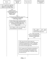
- FIG. 3 is a schematic diagram of an interactive process of an image frame loss detection method according to an embodiment of this disclosure. As shown in FIG. 3 , the method includes the following steps.
- S301 A server acquires first coded data respectively corresponding to a plurality of first image frames.
- the server transmits the first coded data respectively corresponding to the plurality of first image frames to a terminal device.
- the server transmits the first coded data respectively corresponding to the plurality of first image frames to a test device.
- S304 The terminal device performs image rendering on the plurality of first image frames based on the first coded data respectively corresponding to the plurality of first image frames.
- S305 The terminal device displays at least one second image frame determined by the rendering.
- a photosensitive sensor collects a color signal corresponding to each of the at least one second image frame.
- the test device acquires a color signal respectively corresponding to the at least one second image frame determined by a photosensitive sensor.
- test device converts the color signal respectively corresponding to the at least one second image frame collected by the photosensitive sensor, to determine the second coded data respectively corresponding to the at least one second image frame.
- the test device compares the first coded data respectively corresponding to the plurality of first image frames from the server with the second coded data respectively corresponding to the at least one second image frame, to determine a frame loss detection result.
- the first coded data respectively corresponding to the plurality of first image frames may be generated by the server, or the first coded data respectively corresponding to the plurality of first image frames is received by the server from other servers.
- the test device may also acquire the color signal respectively corresponding to the at least one second image frame in other manners, and it is not limited that the color signal respectively corresponding to the at least one second image frame is required to be collected and transmitted by the photosensitive sensor.
- first image frames of 5 colors including red, blue, yellow, white, and black are transmitted in a round-robin fashion, after the terminal device renders and displays each of the first image frames, for example, 5 frames are actually lost after the red image frame, in this case, the terminal device still displays the blue image frame. In this way, the test device cannot detect the frame loss that has occurred.
- the number of colors of the plurality of first image frames transmitted by the server to the terminal device in a round-robin fashion being large, there is a small color difference between adjacent first image frames. That is, values of the color signal are similar and prone to overlapping, and the frame loss cannot be accurately detected.
- the server may partition each of the plurality of first image frames into M image blocks.
- the coded data corresponding to the each first image frame includes color-coded data respectively corresponding to the M image blocks, M being an integer greater than 1.
- each image block has a color in a first image frame.
- a region corresponding to the each image block has N color options, N being an integer greater than 1. Therefore, image frames of M*N colors can be set in a round-robin fashion in the plurality of first image frames, and it is not necessary to set an excessive quantity of colors. In this way, rich color changes between the plurality of first image frames can be ensured, thereby improving the accuracy of the frame loss detection.
- each color option corresponds to a value of the color-coded data
- the N color options correspond to different values of the color-coded data.
- the color options are in a one-to-one correspondence with the color-coded data.
- the color-coded data corresponding to each color option has a same length, for example, the color-coded data occupies 1 bit.
- the server partitions the each first image frame into 6 image blocks, and the color of the each image block is one of 3 color options. In a current image frame, the colors of different image blocks may be the same or different.
- the server sets the corresponding value of the color-coded data for the each image block. For example, the value of the color-coded data corresponding to white is 1, the value of the color-coded data corresponding to red is 2, and the value of the color-coded data corresponding to black is 3.
- the first coded data respectively corresponding to the plurality of first image frames may have a value of 111111 for the first image frame, 11112 for the second image frame, 111113 for the third image frame, 111121 for the fourth image frame, 111122 for the fifth image frame, and 11123 for the sixth image frame.
- each image frame in response to partitioning the each image frame into M image blocks, and a region corresponding to the each image block has N color options.
- more photosensitive sensors corresponding to the quantity of image blocks are available, which leads to higher complexity of collection and computing for the test device and higher test costs.
- the number of photosensitive sensors may be specifically configured according to an actual application scenario.
- any second image frame is determined by rendering a first image frame. Therefore, each second image frame includes M image blocks, each image block has a color in the second image frame, and the color of the each image block in the second image frame is to be the same as a color of each image block in the corresponding first image frame. For example, a region corresponding to the each image block in the second image frame has N color options.
- any one of the plurality of first image frames or the at least one second image frame includes 3 or 6 image blocks.
- the region corresponding to the each image block may include 3 color options: black, white, and gray.
- the N color options having a large difference between color signals may be assigned, for example, two of the N color options have a largest difference among all possible colors, e.g., black and white, e.g., the 3 color options may be black, white and red, or black, white and blue, and so on.
- Steps S304 and S305 are described as follows.
- a rendering frame rate of the terminal device may be 60 frames per second.
- a frame loss may occur to the plurality of first image frames received by the terminal device compared to the plurality of first image frames transmitted by the server.
- a frame loss may occur to at least one second image frame determined by rendering each received image frame by the terminal device compared to the plurality of first image frames transmitted by the server or the plurality of first image frames received by the terminal device.
- the terminal device successively renders, according to a sequence in which the each first image frame is received, each first image frame based on the first coded data corresponding to the each first image frame.
- the coded data corresponding to the each first image frame that is received is decoded to determine a decoding result, and the first image frame is rendered and displayed according to the decoding result.
- Step S306 is described as follows.
- Scheme I Use a detection tool, such as a log capture tool (named as Systrace) provided by the Android system, to capture a system log and determine a Log of the terminal device, and then analyze the captured Log through a script to determine the information about the second image frame displayed on the terminal device.
- Scheme II Continuously capture, through a system command of the terminal device, such as a performance test tool PerfDog, the information about the image frame displayed on the terminal device.
- the detection tool in scheme I is complicated to use, a technician who is very familiar with the system is required to analyze the result, and the analysis process takes a long time, which is not suitable for testing a large number of devices.
- scheme II by consideration of security issues, the system command of the terminal device is clipped, and the command information cannot be collected on the terminal device, resulting in the failure to detect the frame loss of the terminal device.
- the frame loss detection method provided in the related art has the problem of low frame loss detection efficiency.
- this disclosure may arrange a photosensitive sensor on the terminal device.
- the color signal of the image frame displayed on the terminal device may be collected by the photosensitive sensor, and the test device may convert the color signal to determine the second coded data of the image frame.
- the second coded data of the determined image frame is compared with the first coded data of the image frame determined from the server, so that the frame loss detection can be realized, and the efficiency of the frame loss detection can be improved.
- a photosensitive sensor may be arranged in each of regions corresponding to the M image blocks of the terminal device.
- the M photosensitive sensors respectively output a color signal of the region corresponding to each image block in the second image frame.
- the color signal may be a brightness value of at least one color channel.
- the color signal is (255, 255, 255) in terms of three RGB color channels.
- step S308 it is to be understood that, in order to determine, through comparison, whether the at least one second image frame rendered and displayed on the terminal device corresponds to the plurality of first image frames transmitted by the server, the color signal respectively corresponding to the at least one second image frame is required to be converted to the second coded data respectively corresponding to the at least one second image frame, so as to perform the frame loss detection by comparing the second coded data respectively corresponding to the at least one second image frame with the first coded data respectively corresponding to the plurality of first image frames transmitted by the server.
- the color signal is used for representing a color of each image block.
- the color is black in response to the brightness value of a color channel being 0, the color is white in response to the brightness value being 255, and the color is gray in response to the brightness value being 100-150.
- a brightness value (0, 0, 0) for three color channels represents black
- a brightness value (255, 0, 0) for three color channels represents red
- a brightness value (255, 255, 255) for three color channels represents white, and so on.
- the color-coded data of each image block may be determined based on the color signal. For example, the value of color-coded data corresponding to the color signal may be determined according to a correspondence between the color signal and the value of color-coded data.
- the corresponding value of the color-coded data is determined as 1.
- the corresponding value of the color-coded data is determined as 2.
- the corresponding value of the color-coded data is determined as 3.
- the second coded data respectively corresponding to the at least one second image frame is determined.
- the plurality of first image frames and the at least one second image frame each include 6 image blocks, a region corresponding to each image block has 3 color options, and the second coded data respectively corresponding to the at least one second image frame is successively converted to have a value of 111111, 11112, and 111 123 by using the collected color signal, i.e., converting is a kind of numerical coding.
- the corresponding color signal may be determined as a corresponding color based on a preset error value. For example, in response to a color signal corresponding to white having a brightness value differing from 0 by ⁇ 10, i.e., [-10, + 10], the value of the color-coded data corresponding to white is 1, and 10 is the preset error value. In response to the quantity of color channels greater than or equal to 2, each color channel is to be assigned a corresponding error value.
- a frame loss detection result includes determining whether a frame loss occurs, and the lost frames in response to the frame loss occurring.
- the value of second coded data respectively corresponding to the at least one second image frame determined based on the color signal collected by the photosensitive sensor are successively 111111, 11112, 111123
- the first coded data respectively corresponding to the plurality of first image frames and the second coded data respectively corresponding to the at least one second image frame each include color-coded data respectively corresponding to M image blocks, M being an integer greater than 1, and each image block has a color in the image frame. Since each image frame is partitioned into a plurality of image blocks, during detection of the image frame loss, the problem of low frame loss detection accuracy is not caused due to relatively few image frames in a round-robin fashion.
- the photosensitive sensor may collect the color signal of the at least one image frame, and the coded data respectively corresponding to the at least one image frame is determined by converting the corresponding color signal.
- the technical solution of this disclosure has a relatively simple process, thereby improving the frame loss detection efficiency.
- the frame loss is easily caused due to the impact of the quality of the network or the rendering ability of the terminal device in response to performing the image rendering. If a relatively small number of frames are lost, there is less impact on watching experience of the user. If a relatively large number of frames are lost, freezing and unsmoothness can be obviously felt, which has great impact on the watching experience of the user.
- the frame loss situation is further analyzed and determined, and it is determined, based on the image frame loss rate and the preset frame loss rate, whether requirements for the frame rate are satisfied.
- FIG. 4 is a schematic flowchart of an image frame loss detection method according to an embodiment of this disclosure.
- this embodiment of this disclosure after it is determined that the frame loss occurs, it is determined, according to the coded data respectively corresponding to the plurality of image frames and the coded data respectively corresponding to the at least one image frame from the server, whether a frame rate requirement is satisfied. Specifically, the process shown in FIG. 4 is as follows.
- a test device determines an image frame loss rate according to the first coded data corresponding to the plurality of first image frames and the second coded data corresponding to the at least one second image frame.
- the test device determines that a frame rate requirement is not satisfied in response to the image frame loss rate greater than a preset frame loss rate.
- test device determines that the frame rate requirement is satisfied in response to the image frame loss rate less than or equal to the preset frame loss rate.
- the test device may determine, by comparing the first coded data corresponding to the plurality of first image frames with the second coded data corresponding to the at least one second image frame from the server, a quantity of image frames by which the at least one second image frame is less than the plurality of first image frames transmitted by the server.
- a ratio of the quantity of missing image frames to the quantity of the plurality of first image frames transmitted by the server is used as the image frame loss rate.
- preset frame loss rates may be set according to an actual application scenario and a detection requirement.
- the preset frame loss rate is 10%.
- first indication information for indicating that the frame loss occurs in the at least one second image frame is generated.
- second indication information for indicating that the frame rate requirement is not satisfied is generated.
- the test device may transmit the first indication information to any device having a display function to display the first indication information to the user, or the test device may directly display the first indication information.
- the test device may transmit the second indication information to any device having a display function to display the second indication information to the user, or the test device may directly display the second indication information.
- the test device determines the image frame loss rate according to the first coded data corresponding to the plurality of first image frames and the second coded data corresponding to the at least one second image frame that are from the server. In response to the image frame loss rate greater than the preset frame loss rate, it is determined that the frame rate requirement is not satisfied, and in response to the image frame loss rate less than or equal to the preset frame loss rate, it is determined that the frame rate requirement is satisfied. Identifying whether the frame rate requirement is satisfied helps to effectively identify an impact of a frame rate on the watching experience of the user.
- steps in the flowcharts of the embodiments are displayed sequentially according to instructions of arrows, these steps are not necessarily performed sequentially according to a sequence instructed by the arrows. Unless otherwise explicitly specified in this specification, execution of the steps is not strictly limited, and the steps may be performed in other sequences.
- at least some steps in the flowcharts of the foregoing embodiments may include a plurality of steps or a plurality of stages. The steps or the stages are not necessarily performed at the same moment, but may be performed at different moments. The steps or the stages are not necessarily performed in sequence, but may be performed in turn or alternately with another step or at least some of steps or stages of the another step.
- FIG. 5 is a schematic block diagram of a test device according to an embodiment of this disclosure. As shown in FIG. 5 , the test device includes:
- Each of the first image frames and each of the at least one second image frame are partitioned into M image blocks.
- the first coded data corresponding to a first image frame includes color-coded data corresponding to each of the M image blocks in the first image frame.
- the second coded data corresponding to a second image frame includes color-coded data corresponding to each of the M image blocks in the second image frame, and M is an integer greater than 1.
- Each image block has a color in a corresponding image frame.
- a region corresponding to the each image block has N color options, N being an integer greater than 1, and a color of the each image block is one of the N color options.
- each of the N color options corresponds to a value of the color-coded data, and different color options correspond to different values of the color-coded data.
- the color-coded data corresponding to each of the N color options has a same length.
- the test device further includes a determination unit 550, configured to perform a frame rate test according to the first coded data respectively corresponding to the plurality of first image frames and the second coded data respectively corresponding to the at least one second image frame, in response to the comparison unit 540 determining that a frame loss occurs.
- a determination unit 550 configured to perform a frame rate test according to the first coded data respectively corresponding to the plurality of first image frames and the second coded data respectively corresponding to the at least one second image frame, in response to the comparison unit 540 determining that a frame loss occurs.
- the determination unit 550 is further configured to: determine an image frame loss rate according to the first coded data corresponding to the plurality of first image frames and the second coded data corresponding to the at least one second image frame; determine that a frame rate requirement is not satisfied in response to the image frame loss rate greater than a preset frame loss rate; and determine that the frame rate requirement is satisfied in response to the image frame loss rate less than or equal to the preset frame loss rate.
- the color signal includes a brightness value of at least one color channel.
- FIG. 6 is a schematic block diagram of a terminal device 600 according to an embodiment of this disclosure. As shown in FIG. 6 , the terminal device 600 includes:
- Each of the first image frames and each of the at least one second image frame are partitioned into M image blocks.
- the first coded data corresponding to a first image frame includes color-coded data corresponding to each of the M image blocks in the first image frame.
- the second coded data corresponding to a second image frame includes color-coded data corresponding to each of the M image blocks in the second image frame, and M is an integer greater than 1.
- Each image block has a color in a corresponding image frame.
- a region corresponding to the each image block has N color options, N being an integer greater than 1.
- each of the N color options corresponds to a value of the color-coded data, and the N color options correspond to different values of the color-coded data.
- the color-coded data corresponding to each of the N color options has a same length.
- a photosensitive sensor is arranged on a region corresponding to each image block in the at least one second image frame.
- FIG. 7 is a schematic block diagram of a server 700 according to an embodiment of this disclosure. As shown in FIG. 7 , the server 700 includes:
- the transmission unit 720 is further configured to: transmit the first coded data respectively corresponding to the plurality of first image frames to a test device, so that the test device determines the second coded data respectively corresponding to the at least one second image frame based on the color signal collected by the photosensitive sensor after acquiring the color signal, and compares the first coded data corresponding to the plurality of first image frames with the second coded data corresponding to the at least one second image frame, to determine a frame loss detection result.
- Each of the first image frames and each of the at least one second image frame are partitioned into M image blocks.
- the first coded data corresponding to a first image frame includes color-coded data corresponding to each of the M image blocks in the first image frame.
- the second coded data corresponding to a second image frame includes color-coded data corresponding to each of the M image blocks in the second image frame, and M is an integer greater than 1.
- Each image block has a color in a corresponding image frame.
- a region corresponding to the each image block has N color options, N being an integer greater than 1.
- each of the N color options corresponds to a value of the color-coded data, and the N color options correspond to different values of the color-coded data.
- the color-coded data corresponding to each of the N color options has a same length.
- the acquisition unit 710 is further configured to: partition each of the plurality of first image frames into M image blocks; code colors of the M image blocks to determine color-coded data respectively corresponding to the M image blocks; and combine the color-coded data respectively corresponding to the M image blocks to determine the first coded data corresponding to the first image frame.
- the server provided in the foregoing embodiments may execute the technical solutions on the server side in the foregoing method embodiments. An implementation principle and a technical effect thereof are similar. Details are not described herein again.
- FIG. 8 is a schematic structural diagram of a computer device 800 according to an embodiment of this disclosure.
- the test device shown in FIG. 8 includes one or more processors 810, and the one or more processors 810 can invoke and run computer-readable instructions from a memory, to implement the method in the embodiments of this disclosure.
- the computer device 800 may further include a memory 820.
- the one or more processors 810 may invoke the computer-readable instructions from the memory 820 and run the computer-readable instructions, to implement the method in the embodiments of this disclosure.
- the memory 820 may be a component independent of the one or more processors 810, or may be integrated into the one or more processors 810.
- the test device 800 may further include a transceiver 830.
- One or more processors 810 may control the transceiver 830 to communicate with other devices.
- the transceiver may transmit information or data to other devices, or receive information or data transmitted by other devices.
- the transceiver 830 may include a transmitter and a receiver.
- the transceiver 830 may further include an antenna, and a quantity of the antenna can be one or more.
- the computer device 800 may be a test device, and may implement a process corresponding to the test device in the methods of the embodiments of this disclosure.
- the computer device 800 may be a terminal device, and may implement a process corresponding to the terminal device in the methods of the embodiments of this disclosure.
- the computer device 800 may be a server, and may implement a process corresponding to the server in the methods of the embodiments of this disclosure.
- the one or more processors in this embodiment of this disclosure may be an integrated circuit chip having a signal processing capability.
- steps in the foregoing method embodiments can be implemented by using a hardware integrated logical circuit in the one or more processors, or by using instructions in a form of software.
- the foregoing one or more processors may be one or more general-purpose processors, one or more digital signal processors (DSP), an application-specific integrated circuit (ASIC), a field-programmable gate array (FPGA), or another programmable logic device, discrete gate or transistor logic device, or discrete hardware component.
- DSP digital signal processors
- ASIC application-specific integrated circuit
- FPGA field-programmable gate array
- the one or more processors can implement or execute methods, steps, and logical block diagrams disclosed in the embodiments of this disclosure.
- the one or more general-purpose processors may be one or more microprocessors, or the one or more processors may be any one or more conventional processors and the like.
- the steps of the methods disclosed with reference to the embodiments of this disclosure may be directly performed and completed by using one or more hardware decoding processors, or may be performed and completed by using a combination of hardware and software modules in the one or more decoding processors.
- the software module may be stored in a storage medium that is mature in the art, such as a RAM, a flash memory, a read-only memory (ROM), a programmable ROM, an electrically erasable programmable memory, or a register.
- the storage medium is located in the memory.
- the one or more processors read information in the memory and complete the steps of the foregoing methods in combination with hardware thereof.
- the memory in the embodiments of this disclosure may be a volatile memory or a nonvolatile memory, or may include a volatile memory and a nonvolatile memory.
- the non-volatile memory may be a read-only memory (ROM), a programmable read-only memory (PROM), an erasable programmable read-only memory (EPROM), an electrically erasable programmable read-only memory (EEPROM) or a flash memory.
- the volatile memory may be a random access memory (RAM), used as an external cache.
- RAMs may be used, for example, a static random access memory (Static RAM, SRAM), a dynamic random access memory (Dynamic RAM, DRAM), a synchronous dynamic random access memory (Synchronous DRAM, SDRAM), a double data rate synchronous dynamic random access memory (Double Data Rate SDRAM, DDR SDRAM), an enhanced synchronous dynamic random access memory (Enhanced SDRAM, ESDRAM), a synchronous link dynamic random access memory (Synchlink DRAM, SLDRAM), and a direct rambus dynamic random access memory (Direct Rambus RAM, DR RAM).
- Static RAM static random access memory
- DRAM dynamic random access memory
- DRAM synchronous dynamic random access memory
- SDRAM double data rate synchronous dynamic random access memory
- Enhanced SDRAM, ESDRAM enhanced synchronous dynamic random access memory
- Synchlink DRAM, SLDRAM synchronous link dynamic random access memory
- Direct Rambus RAM Direct Rambus RAM
- the memory is an example but is not intended for limitation.
- the memory in the embodiments of this disclosure may alternatively be a static random access memory (SRAM), a dynamic random access memory (DRAM), a synchronous dynamic random access memory (SDRAM), a double data rate synchronous dynamic random access memory (DDR SDRAM), an enhanced synchronous dynamic random access memory (ESDRAM), a synchlink dynamic random access memory (SLDRAM), a direct rambus random access memory (DR RAM), and the like.
- SRAM static random access memory
- DRAM dynamic random access memory
- SDRAM synchronous dynamic random access memory
- DDR SDRAM double data rate synchronous dynamic random access memory
- ESDRAM enhanced synchronous dynamic random access memory
- SLDRAM synchlink dynamic random access memory
- DR RAM direct rambus random access memory
- An embodiment of this disclosure further provides one or more computer readable storage media, configured to store computer-readable instructions.
- the computer-readable storage media may be applied to the electronic device in the embodiments of this disclosure, and the computer-readable instructions cause a computer to perform corresponding procedures in various methods in the embodiments of this disclosure. For brevity, details are not described herein again.
- An embodiment of this disclosure further provides a computer-readable instruction product, including computer-readable instructions.
- the computer program product may be applied to the electronic device in the embodiments of this disclosure, and the computer-readable instructions cause a computer to perform corresponding procedures in the methods in the embodiments of this disclosure.
- the computer-readable instructions cause a computer to perform corresponding procedures in the methods in the embodiments of this disclosure.
- the disclosed device, apparatus, and method may be implemented in other manners.
- the described apparatus embodiment is merely exemplary.
- the unit division is merely a logical function division and may be other division during actual implementation.
- a plurality of units or components may be combined or integrated into another system, or some features may be ignored or not performed.
- the shown or discussed mutual couplings or direct couplings or communication connections may be implemented through some interfaces.
- the indirect couplings or communication connections between the apparatus or units may be implemented in electronic, mechanical, or other forms.
- the units described as separate parts may or may not be physically separate, and components displayed as units may or may not be physical units, that is, may be located in one position, or may be distributed on a plurality of network units. Some or all of the units may be selected according to an actual requirement to achieve the objectives of the solutions in the embodiments.
- the functions may be stored in a computer-readable storage medium.
- the software product is stored in a storage medium, and includes several instructions for instructing a computer device (which may be a personal computer, a server, or a network device) to perform all or some of the steps of the methods described in the embodiments of this disclosure.
- the foregoing storage medium includes: any medium that can store program codes, such as a USB flash disk, a removable hard disk, a read-only memory (ROM), a random access memory (RAM), a magnetic disk, or an optical disk.
Landscapes
- Engineering & Computer Science (AREA)
- Multimedia (AREA)
- Physics & Mathematics (AREA)
- General Physics & Mathematics (AREA)
- Theoretical Computer Science (AREA)
- Signal Processing (AREA)
- Computer Vision & Pattern Recognition (AREA)
- Quality & Reliability (AREA)
- Computer Networks & Wireless Communication (AREA)
- Databases & Information Systems (AREA)
- Computer Security & Cryptography (AREA)
- Business, Economics & Management (AREA)
- Life Sciences & Earth Sciences (AREA)
- Biodiversity & Conservation Biology (AREA)
- Ecology (AREA)
- Emergency Management (AREA)
- Environmental & Geological Engineering (AREA)
- Environmental Sciences (AREA)
- Remote Sensing (AREA)
- Image Analysis (AREA)
- Testing, Inspecting, Measuring Of Stereoscopic Televisions And Televisions (AREA)
Abstract
Description
- This application claims priority to
Chinese Patent Application No. 2021101054579, entitled "METHOD, APPARATUS, DEVICE, AND STORAGE MEDIUM FOR DETECTING IMAGE FRAME LOSS" and filed with the China National Intellectual Property Administration on January 26, 2021 - Embodiments of this disclosure relate to the field of artificial intelligence technologies, and in particular, to a method, a device, a storage medium, and a computer program product for detecting an image frame loss.
- With the continuous development of image processing technologies, in order to meet high requirements of a user for smoothness of display of a terminal device, it is necessary to detect whether a frame loss occurs to image frames displayed on the terminal device.
- In a conventional method, each of a plurality of to-be displayed image frames is assigned a color. It is determined, by performing a round-robin fashion on the plurality of image frames according to different colors, whether a frame loss occurs to image frames displayed on a terminal device compared to a plurality of to-be displayed image frames.
- However, in response to using a relatively small number of image frames in a round-robin fashion, it is assumed that the quantity of image frames in a round-robin fashion is n. For the image frames displayed on the terminal device, in response to n frames or a number of frames equal to a multiple of n being lost compared to the plurality of to-be displayed image frames, actual image frames currently received by the terminal device are the same as the image frames that are to be received in response to no frame loss occurring. Therefore, the terminal device cannot detect the frame loss, which causes low accuracy of frame loss detection.
- Embodiments of this disclosure provide a method, apparatus, device, storage medium, and computer program product for detecting image frame loss.
- According to a first aspect, an image frame loss detection method is provided, applicable to a test device, the method including: acquiring first coded data respectively corresponding to a plurality of first image frames; acquiring a color signal respectively corresponding to at least one second image frame, the at least one second image frame being determined by a terminal device through performing image rendering on the plurality of first image frames based on the first coded data respectively corresponding to the plurality of first image frames; converting the color signal respectively corresponding to the at least one second image frame to determine second coded data respectively corresponding to the at least one second image frame; and comparing the first coded data corresponding to the plurality of first image frames with the second coded data corresponding to the at least one second image frame, to determine a frame loss detection result; the first coded data respectively corresponding to the plurality of first image frames and the second coded data respectively corresponding to the at least one second image frame each including color-coded data respectively corresponding to M image blocks, M being an integer greater than 1, and each image block having a color in the image frame.
- According to a second aspect, an image frame loss detection method is provided, applicable to a terminal device, the method including: acquiring first coded data respectively corresponding to a plurality of first image frames; performing image rendering on the plurality of first image frames based on the first coded data respectively corresponding to the plurality of first image frames; displaying at least one second image frame determined by the rendering; collecting, by a photosensitive sensor that is arranged, a color signal corresponding to each of the at least one second image frame; transmitting the color signal respectively corresponding to the at least one second image frame to a test device, so that the test device determines second coded data respectively corresponding to the at least one second image frame based on the color signal, and compares the first coded data corresponding to the plurality of first image frames with the second coded data corresponding to the at least one second image frame, to determine a frame loss detection result; the first coded data respectively corresponding to the plurality of first image frames and the second coded data respectively corresponding to the at least one second image frame each including color-coded data respectively corresponding to M image blocks, M being an integer greater than 1, and each image block having a color in the image frame.
- According to a third aspect, an image frame loss detection method is provided, applicable to a server, the method including: acquiring first coded data respectively corresponding to a plurality of first image frames; transmitting the first coded data respectively corresponding to the plurality of first image frames to a terminal device, so that the terminal device performs image rendering on the plurality of first image frames based on the first coded data respectively corresponding to the plurality of first image frames, displays at least one second image frame determined by the rendering, and collects a color signal respectively corresponding to the at least one second image frame by a photosensitive sensor arranged in the terminal device during displaying each of the at least one second image frame; and transmitting the first coded data respectively corresponding to the plurality of first image frames to a test device, so that the test device determines the second coded data respectively corresponding to the at least one second image frame based on the color signal collected by the photosensitive sensor after acquiring the color signal, and compares the first coded data corresponding to the plurality of first image frames with the second coded data corresponding to the at least one second image frame, to determine a frame loss detection result; the first coded data respectively corresponding to the plurality of first image frames and the second coded data respectively corresponding to the at least one second image frame each including color-coded data respectively corresponding to M image blocks, M being an integer greater than 1, and each image block having a color in the image frame.
- According to a fourth aspect, a test device is provided, including a first acquisition unit, a second acquisition unit, a conversion unit, and a comparison unit. The first acquisition unit is configured to acquire first coded data respectively corresponding to a plurality of first image frames. The second acquisition unit is configured to configured to acquire a color signal respectively corresponding to at least one second image frame, the at least one second image frame being determined by a terminal device through performing image rendering on the plurality of first image frames based on the first coded data respectively corresponding to the plurality of first image frames. The conversion unit is configured to convert the color signal respectively corresponding to the at least one second image frame to determine second coded data respectively corresponding to the at least one second image frame. The comparison unit is configured to compare the first coded data corresponding to the plurality of first image frames with the second coded data corresponding to the at least one second image frame, to determine a frame loss detection result; the first coded data respectively corresponding to the plurality of first image frames and the second coded data respectively corresponding to the at least one second image frame each including color-coded data respectively corresponding to M image blocks, M being an integer greater than 1, and each image block having a color in the image frame.
- According to a fifth aspect, a terminal device is provided, including an acquisition unit, a rendering unit, and a display unit. The acquisition unit is configured to acquire first coded data respectively corresponding to a plurality of first image frames from a server. The rendering unit is configured to perform image rendering on the plurality of first image frames based on the first coded data respectively corresponding to the plurality of first image frames. The display unit is configured to display at least one second image frame determined by the rendering; collect, by a photosensitive sensor that is arranged, a color signal corresponding to each of the at least one second image frame; and transmit the color signal respectively corresponding to the at least one second image frame to a test device, so that the test device determines second coded data respectively corresponding to the at least one second image frame based on the color signal, and compares the first coded data corresponding to the plurality of first image frames with the second coded data corresponding to the at least one second image frame, to determine a frame loss detection result; the first coded data respectively corresponding to the plurality of first image frames and the second coded data respectively corresponding to the at least one second image frame each including color-coded data respectively corresponding to M image blocks, M being an integer greater than 1, and each image block having a color in the image frame.
- According to a sixth aspect, a server is provided, including an acquisition unit and a transmission unit. The acquisition unit is configured to acquire first coded data respectively corresponding to a plurality of first image frames. The transmission unit is configured to transmit the first coded data respectively corresponding to the plurality of first image frames to a terminal device, so that the terminal device performs image rendering on the plurality of first image frames based on the first coded data respectively corresponding to the plurality of first image frames, displays at least one second image frame determined by the rendering, and collects a color signal respectively corresponding to the at least one second image frame by a photosensitive sensor arranged in the terminal device during displaying each of the at least one second image frame; and transmit the first coded data respectively corresponding to the plurality of first image frames to a test device, so that the test device determines the second coded data respectively corresponding to the at least one second image frame based on the color signal collected by the photosensitive sensor after acquiring the color signal, and compares the first coded data corresponding to the plurality of first image frames with the second coded data corresponding to the at least one second image frame, to determine a frame loss detection result; the first coded data respectively corresponding to the plurality of first image frames and the second coded data respectively corresponding to the at least one second image frame each including color-coded data respectively corresponding to M image blocks, M being an integer greater than 1, and each image block having a color in the image frame.
- According to a seventh aspect, a computer device is provided, including: one or more processors and a memory, the memory being configured to store computer-readable instructions, the one or more processors being configured to invoke and run the computer-readable instructions stored in the memory, to perform the steps of the method in the embodiments of this disclosure.
- According to an eighth aspect, one or more computer-readable storage media are provided, configured to store computer-readable instructions, the computer-readable instructions causing a computer to perform the steps of the method in the embodiments of this disclosure.
- According to a ninth aspect, a computer program product is provided, including computer-readable instructions, the computer-readable instructions causing a computer to perform the steps of the method in the embodiments of this disclosure.
- To describe the technical solutions in the embodiments of this disclosure more clearly, the following briefly introduces the accompanying drawings required for describing the embodiments. Apparently, the accompanying drawings in the following description show merely some embodiments of this disclosure, and a person of ordinary skill in the art may still derive other drawings from these accompanying drawings without creative efforts.
-
FIG. 1 is a schematic structural diagram of an image frame loss detection system according to an embodiment of this disclosure. -
FIG. 2 is a schematic structural diagram of an image frame loss detection system according to an embodiment of this disclosure. -
FIG. 3 is a schematic flowchart of an image frame loss detection method according to an embodiment of this disclosure. -
FIG. 4 is a schematic diagram of an interactive process of an image frame loss detection method according to an embodiment of this disclosure. -
FIG. 5 is a schematic block diagram of a test device according to an embodiment of this disclosure. -
FIG. 6 is a schematic block diagram of a terminal device according to an embodiment of this disclosure. -
FIG. 7 is a schematic block diagram of a server according to an embodiment of this disclosure. -
FIG. 8 is a schematic structural diagram of a computer device according to an embodiment of this disclosure. - The following describes the technical solutions in the embodiments of this disclosure with reference to the accompanying drawings in the embodiments of this disclosure. Apparently, the described embodiments are some rather than all of the embodiments of this disclosure. For the embodiments of this application, all other embodiments obtained by a person of ordinary skill in the art without creative efforts shall fall within the protection scope of this application.
- Currently, a plurality of image frames in a round-robin fashion are transmitted to a terminal device through a cloud server. The plurality of image frames in a round-robin fashion include a plurality of image frames of different colors. For example, image frames of 5 colors including red, blue, yellow, white, and black are transmitted in a round-robin fashion, so that the terminal device can render and display the image frames of different colors, and then the image frame rendered by the terminal device is compared with the image frame transmitted by the server to determine whether a frame loss occurs. However, a relatively small number of image frames in a round-robin fashion easily bring an error in frame loss detection. For example, in response to performing the round-robin fashion on the image frames according to the 5 colors including red, blue, yellow, white, and black, after the terminal device renders and displays each image frame, it is assumed that 5 frames are actually lost after the red image frame. In this case, the terminal device is to determine a blue image frame in a next round by rendering. In this case, the frame loss that has occurred cannot be detected.
- Based on the above, the current frame loss detection technology cannot guarantee the accuracy of the frame loss detection. In order to resolve this technical problem, in this disclosure, the image frame is partitioned into a plurality of image blocks, and each image block has a color in one image frame, so that each image frame has rich colors, thereby improving the accuracy of the frame loss detection.
-
FIG. 1 is a schematic structural diagram of an image frame loss detection system according to an embodiment of this disclosure. As shown inFIG. 1 , the image frame loss detection system 100 includes aserver 110, aterminal device 120, and atest device 130. Theserver 110 is respectively connected to theterminal device 120 and thetest device 130 in a wired or wireless manner. Theterminal device 120 is connected to thetest device 130 in a wired or wireless manner. For example, one or morephotosensitive sensors 121 may be arranged on theterminal device 120, and thephotosensitive sensor 121 is connected to thetest device 130. - The
server 110 may be a cloud server. In different application scenarios, theserver 110 may be configured to implement different functions. For example, in a cloud gaming scenario, theserver 110 may be a cloud gaming server. In this embodiment, theserver 110 is configured to code colors of image blocks into which a plurality of to-be-displayed image frames are partitioned, acquire coded data respectively corresponding to the plurality of image frames, and successively transmit the coded data respectively corresponding to the plurality of image frames to theterminal device 120 and/or thetest device 130. - Cloud gaming, also referred to as gaming on demand, is an online gaming technology based on the cloud computing technology. The cloud gaming technology enables a thin client with relatively limited graphics processing and data computing capabilities to run a high-quality game. In a cloud gaming scenario, the game is run on the cloud server rather than a game terminal of a player, and the cloud server renders the game scene into a video and audio stream, and transmits the video and audio stream to the game terminal of the player through a network. The game terminal of the player is not required to have powerful graphics computing and data processing capabilities, but only required to have a basic streaming media playback capability and the capability of acquiring instructions inputted by the player and transmitting the instructions to the cloud server.
- Based on the above technical means, in the cloud gaming scenario, a game image run on a server end is to be transmitted to the terminal device for display. In addition to this, the server may further transmit other images to the terminal device for real-time display, for example, a stored video image, a read video image of an online program, an acquired live video image, and the like. In the process that the server transmits a plurality of image frames corresponding to the game image, a video image, and the like to a terminal device of a user in real time for display, the frame loss is caused due to the network jitter, the coding and decoding efficiency of the terminal device, and the efficiency of transmission for display, which brings the user freezing and unsmooth watching experience. Therefore, a set of quantifiable indicators are required to collect statistics on the frame loss.
- The solution of this disclosure is not limited to application to the cloud gaming test scenario, and may further be application to other scenarios where the frame loss is required to be tested for the terminal device.
- Exemplarily, the
terminal device 120 may be any terminal device with a display function, such as a mobile phone, a pad, a computer, a TV, a virtual reality (VR) terminal device, an augmented reality (AR) terminal device, a terminal device related to industrial control, a terminal device related to self driving, a terminal device related to remote medical, a terminal device related to a smart city, a terminal device related to a smart home, and the like. The terminal device in this embodiment of this disclosure may also be a wearable device. The wearable device may also be referred to as a wearable smart device, and is a collective term for wearable devices developed by intelligently designing daily wears based on a wearable technology, for example, glasses, gloves, a watch, clothing, and shoes. The wearable device is a portable device that is directly worn on a human body or integrated into a user's clothing or accessory. In some embodiments, theterminal device 120 may further be only a display device, for example, a display. The display may be a flexible display, and the display may further be arranged to be in a non-rectangular irregular shape, that is, a special-shaped display. The display may be a liquid crystal display (LCD), an organic light-emitting diode (OLED) display, or the like. Theterminal device 120 may be stationary or mobile. - The
terminal device 120 receives the coded data of the plurality of to-be-displayed image frames transmitted by theserver 110, performs image rendering based on the coded data of the plurality of image frames, and then displays at least one image frame that is rendered. - For example, the
photosensitive sensor 121 arranged on theterminal device 120 is configured to acquire a color signal of the image block on the image frame displayed on theterminal device 120. For example, thephotosensitive sensor 121 is in a one-to-one correspondence with the image block in each image frame. In other words, eachphotosensitive sensor 121 is arranged on a region where an image block is displayed on the display of the terminal device. -
FIG. 2 is a schematic structural diagram of an image frame loss detection system according to an embodiment of this disclosure. As shown inFIG. 2 , the image frame displayed on theterminal device 120 includes 6 image blocks. Onephotosensitive sensor 121 is arranged on a region where each image block is displayed on a display of theterminal device 120. Eachphotosensitive sensor 121 is connected to thetest device 130 in a wired or wireless manner. Eachphotosensitive sensor 121 is configured to collect a light signal displayed on the corresponding image block, and convert the light signal to a color signal corresponding to the image block. - In an embodiment, a photosensitive sensor is correspondingly arranged on a region where each image block is displayed on the display of the terminal device. The color signal corresponding to the each second image frame includes a color signal corresponding to the each image block in the second image frame. The color signal corresponding to the each image block is determined by the corresponding photosensitive sensor collecting a light signal displayed on the each image block and then converting the light signal to the color signal. The color signal corresponding to the each image block is transmitted from the corresponding photosensitive sensor to the
test device 130. - It is to be understood that
FIG. 2 merely shows an example. Each image frame may include more or fewer image blocks, and a corresponding quantity of photosensitive sensors are arranged according to a quantity of image blocks. In addition, each image block has one color in each image frame, and a region corresponding to each image block has N colors. - With reference to
FIG. 1 , thetest device 130 determines the second coded data respectively corresponding to the at least one second image frame rendered by theterminal device 120. For example, thetest device 130 receives the color signal respectively corresponding to the at least one second image frame transmitted by thephotosensitive sensor 121, and converts the color signal corresponding to the each second image frame to the corresponding second coded data. - This disclosure is specifically described below by using several embodiments.
-
FIG. 3 is a schematic diagram of an interactive process of an image frame loss detection method according to an embodiment of this disclosure. As shown inFIG. 3 , the method includes the following steps. - S301: A server acquires first coded data respectively corresponding to a plurality of first image frames.
- S302: The server transmits the first coded data respectively corresponding to the plurality of first image frames to a terminal device.
- S303: The server transmits the first coded data respectively corresponding to the plurality of first image frames to a test device.
- S304: The terminal device performs image rendering on the plurality of first image frames based on the first coded data respectively corresponding to the plurality of first image frames.
- S305: The terminal device displays at least one second image frame determined by the rendering.
- S306: A photosensitive sensor collects a color signal corresponding to each of the at least one second image frame.
- S307: The test device acquires a color signal respectively corresponding to the at least one second image frame determined by a photosensitive sensor.
- S308: The test device converts the color signal respectively corresponding to the at least one second image frame collected by the photosensitive sensor, to determine the second coded data respectively corresponding to the at least one second image frame.
- S309: The test device compares the first coded data respectively corresponding to the plurality of first image frames from the server with the second coded data respectively corresponding to the at least one second image frame, to determine a frame loss detection result.
- The first coded data respectively corresponding to the plurality of first image frames may be generated by the server, or the first coded data respectively corresponding to the plurality of first image frames is received by the server from other servers.
- The test device may also acquire the color signal respectively corresponding to the at least one second image frame in other manners, and it is not limited that the color signal respectively corresponding to the at least one second image frame is required to be collected and transmitted by the photosensitive sensor.
- In the conventional method, in response to the number of colors of the plurality of first image frames transmitted by the server to the terminal device in a round-robin fashion being relatively small, for example, first image frames of 5 colors including red, blue, yellow, white, and black are transmitted in a round-robin fashion, after the terminal device renders and displays each of the first image frames, for example, 5 frames are actually lost after the red image frame, in this case, the terminal device still displays the blue image frame. In this way, the test device cannot detect the frame loss that has occurred. In response to the number of colors of the plurality of first image frames transmitted by the server to the terminal device in a round-robin fashion being large, there is a small color difference between adjacent first image frames. That is, values of the color signal are similar and prone to overlapping, and the frame loss cannot be accurately detected.
- Based on the above, in order to determine a more accurate detection result and reduce a detection error, in this embodiment of this disclosure, the server may partition each of the plurality of first image frames into M image blocks. Correspondingly, the coded data corresponding to the each first image frame includes color-coded data respectively corresponding to the M image blocks, M being an integer greater than 1. It is to be understood that each image block has a color in a first image frame. In an embodiment, a region corresponding to the each image block has N color options, N being an integer greater than 1. Therefore, image frames of M*N colors can be set in a round-robin fashion in the plurality of first image frames, and it is not necessary to set an excessive quantity of colors. In this way, rich color changes between the plurality of first image frames can be ensured, thereby improving the accuracy of the frame loss detection.
- It is to be understood that each color option corresponds to a value of the color-coded data, and the N color options correspond to different values of the color-coded data. In other words, the color options are in a one-to-one correspondence with the color-coded data. For example, the color-coded data corresponding to each color option has a same length, for example, the color-coded data occupies 1 bit.
- For example, as shown in
FIG. 2 , the server partitions the each first image frame into 6 image blocks, and the color of the each image block is one of 3 color options. In a current image frame, the colors of different image blocks may be the same or different. The server sets the corresponding value of the color-coded data for the each image block. For example, the value of the color-coded data corresponding to white is 1, the value of the color-coded data corresponding to red is 2, and the value of the color-coded data corresponding to black is 3. For example, the first coded data respectively corresponding to the plurality of first image frames may have a value of 111111 for the first image frame, 11112 for the second image frame, 111113 for the third image frame, 111121 for the fourth image frame, 111122 for the fifth image frame, and 11123 for the sixth image frame. - It is to be understood that in response to partitioning the each image frame into M image blocks, and a region corresponding to the each image block has N color options. In this case, there are M∗N color coding combinations totally, and more image blocks into which the first image frame is partitioned, a more accurate result of the image frame loss detection. However, more photosensitive sensors corresponding to the quantity of image blocks are available, which leads to higher complexity of collection and computing for the test device and higher test costs. The number of photosensitive sensors may be specifically configured according to an actual application scenario.
- Any second image frame is determined by rendering a first image frame. Therefore, each second image frame includes M image blocks, each image block has a color in the second image frame, and the color of the each image block in the second image frame is to be the same as a color of each image block in the corresponding first image frame. For example, a region corresponding to the each image block in the second image frame has N color options.
- For example, any one of the plurality of first image frames or the at least one second image frame includes 3 or 6 image blocks. The region corresponding to the each image block may include 3 color options: black, white, and gray. However, in order to improve the detection accuracy, the N color options having a large difference between color signals may be assigned, for example, two of the N color options have a largest difference among all possible colors, e.g., black and white, e.g., the 3 color options may be black, white and red, or black, white and blue, and so on.
- Steps S304 and S305 are described as follows.
- In an embodiment, a rendering frame rate of the terminal device may be 60 frames per second.
- It is to be understood that, due to the network jitter, a frame loss may occur to the plurality of first image frames received by the terminal device compared to the plurality of first image frames transmitted by the server. Alternatively, due to the impact of the rendering capability, a frame loss may occur to at least one second image frame determined by rendering each received image frame by the terminal device compared to the plurality of first image frames transmitted by the server or the plurality of first image frames received by the terminal device.
- In an embodiment, the terminal device successively renders, according to a sequence in which the each first image frame is received, each first image frame based on the first coded data corresponding to the each first image frame.
- In an embodiment, before the terminal device performs image rendering on the plurality of first image frames, the coded data corresponding to the each first image frame that is received is decoded to determine a decoding result, and the first image frame is rendered and displayed according to the decoding result.
- Step S306 is described as follows.
- In the prior art, in response to acquiring the second image frame rendered by the terminal device and comparing the second image frame with the first image frame transmitted by the server to determine whether the frame loss occurs, the following two schemes are often used. Scheme I: Use a detection tool, such as a log capture tool (named as Systrace) provided by the Android system, to capture a system log and determine a Log of the terminal device, and then analyze the captured Log through a script to determine the information about the second image frame displayed on the terminal device. Scheme II: Continuously capture, through a system command of the terminal device, such as a performance test tool PerfDog, the information about the image frame displayed on the terminal device. However, the detection tool in scheme I is complicated to use, a technician who is very familiar with the system is required to analyze the result, and the analysis process takes a long time, which is not suitable for testing a large number of devices. In scheme II, by consideration of security issues, the system command of the terminal device is clipped, and the command information cannot be collected on the terminal device, resulting in the failure to detect the frame loss of the terminal device.
- In conclusion, the frame loss detection method provided in the related art has the problem of low frame loss detection efficiency. In order to resolve this technical problem, this disclosure may arrange a photosensitive sensor on the terminal device. The color signal of the image frame displayed on the terminal device may be collected by the photosensitive sensor, and the test device may convert the color signal to determine the second coded data of the image frame. Finally, the second coded data of the determined image frame is compared with the first coded data of the image frame determined from the server, so that the frame loss detection can be realized, and the efficiency of the frame loss detection can be improved.
- A photosensitive sensor may be arranged in each of regions corresponding to the M image blocks of the terminal device.
- For example, for any second image frame in the foregoing at least one second image frame, the M photosensitive sensors respectively output a color signal of the region corresponding to each image block in the second image frame. The color signal may be a brightness value of at least one color channel. For example, the color signal is (255, 255, 255) in terms of three RGB color channels.
- For step S308, it is to be understood that, in order to determine, through comparison, whether the at least one second image frame rendered and displayed on the terminal device corresponds to the plurality of first image frames transmitted by the server, the color signal respectively corresponding to the at least one second image frame is required to be converted to the second coded data respectively corresponding to the at least one second image frame, so as to perform the frame loss detection by comparing the second coded data respectively corresponding to the at least one second image frame with the first coded data respectively corresponding to the plurality of first image frames transmitted by the server.
- For example, the color signal is used for representing a color of each image block. For example, for a grayscale image, which has a single color channel, the color is black in response to the brightness value of a color channel being 0, the color is white in response to the brightness value being 255, and the color is gray in response to the brightness value being 100-150. In another example, for a RGB image, which has three color channels, a brightness value (0, 0, 0) for three color channels represents black, a brightness value (255, 0, 0) for three color channels represents red, a brightness value (255, 255, 255) for three color channels represents white, and so on.
- Further, the color-coded data of each image block may be determined based on the color signal. For example, the value of color-coded data corresponding to the color signal may be determined according to a correspondence between the color signal and the value of color-coded data.
- For example, in response to the second image frame being a grayscale image and the brightness value is 255, the corresponding value of the color-coded data is determined as 1. In response to the brightness value between 100 and 150, the corresponding value of the color-coded data is determined as 2. In response to the brightness value being 0, the corresponding value of the color-coded data is determined as 3. Further, the second coded data respectively corresponding to the at least one second image frame is determined.
- For example, it is assumed that the plurality of first image frames and the at least one second image frame each include 6 image blocks, a region corresponding to each image block has 3 color options, and the second coded data respectively corresponding to the at least one second image frame is successively converted to have a value of 111111, 11112, and 111 123 by using the collected color signal, i.e., converting is a kind of numerical coding.
- For example, during the determination of the corresponding color-coded data based on the color signal in this embodiment, the corresponding color signal may be determined as a corresponding color based on a preset error value. For example, in response to a color signal corresponding to white having a brightness value differing from 0 by ± 10, i.e., [-10, + 10], the value of the color-coded data corresponding to white is 1, and 10 is the preset error value. In response to the quantity of color channels greater than or equal to 2, each color channel is to be assigned a corresponding error value.
- In Step S309, a frame loss detection result includes determining whether a frame loss occurs, and the lost frames in response to the frame loss occurring.
- For example, assuming that the value of second coded data respectively corresponding to the at least one second image frame determined based on the color signal collected by the photosensitive sensor are successively 111111, 11112, 111123, it may be learned, through comparison with the value of first coded data respectively corresponding to the plurality of first image frames in the foregoing embodiment, that is, 111111 for the first image frame, 11112 for the second image frame, 111113 for the third image frame, 111121 for the fourth image frame, 111122 for the fifth image frame, and 11123 for the sixth image frame, that the second coded data respectively corresponding to the at least one second image frame is the same as the first coded data corresponding to the first image frame, the second image frame, and the sixth image frame among the plurality of first image frames transmitted by the server. That is to say, a total of 3 image frames including the third image frame to the fifth image frame are lost. Therefore, it is determined that the frame loss occurs in the at least one second image frame displayed on the terminal device.
- In this embodiment of this disclosure, it is determined, through comparison of the first coded data respectively corresponding to the plurality of first image frames from the server with the second coded data respectively corresponding to the at least one second image frame rendered and displayed on the terminal device, whether the frame loss occurs. The first coded data respectively corresponding to the plurality of first image frames and the second coded data respectively corresponding to the at least one second image frame each include color-coded data respectively corresponding to M image blocks, M being an integer greater than 1, and each image block has a color in the image frame. Since each image frame is partitioned into a plurality of image blocks, during detection of the image frame loss, the problem of low frame loss detection accuracy is not caused due to relatively few image frames in a round-robin fashion.
- Further, in this disclosure, the photosensitive sensor may collect the color signal of the at least one image frame, and the coded data respectively corresponding to the at least one image frame is determined by converting the corresponding color signal. Compared with the solution of determining, through script analysis, whether the frame loss occurs, the technical solution of this disclosure has a relatively simple process, thereby improving the frame loss detection efficiency.
- During transmission of the image frame, the frame loss is easily caused due to the impact of the quality of the network or the rendering ability of the terminal device in response to performing the image rendering. If a relatively small number of frames are lost, there is less impact on watching experience of the user. If a relatively large number of frames are lost, freezing and unsmoothness can be obviously felt, which has great impact on the watching experience of the user.
- In order to prevent the user from feeling freezing or unsmoothness during the watching, in this embodiment, the frame loss situation is further analyzed and determined, and it is determined, based on the image frame loss rate and the preset frame loss rate, whether requirements for the frame rate are satisfied.
-
FIG. 4 is a schematic flowchart of an image frame loss detection method according to an embodiment of this disclosure. - Based on the foregoing embodiment, in this embodiment of this disclosure, after it is determined that the frame loss occurs, it is determined, according to the coded data respectively corresponding to the plurality of image frames and the coded data respectively corresponding to the at least one image frame from the server, whether a frame rate requirement is satisfied. Specifically, the process shown in
FIG. 4 is as follows. - S401: A test device determines an image frame loss rate according to the first coded data corresponding to the plurality of first image frames and the second coded data corresponding to the at least one second image frame.
- S402: The test device determines that a frame rate requirement is not satisfied in response to the image frame loss rate greater than a preset frame loss rate.
- S403: The test device determines that the frame rate requirement is satisfied in response to the image frame loss rate less than or equal to the preset frame loss rate.
- For step S401, the test device may determine, by comparing the first coded data corresponding to the plurality of first image frames with the second coded data corresponding to the at least one second image frame from the server, a quantity of image frames by which the at least one second image frame is less than the plurality of first image frames transmitted by the server. A ratio of the quantity of missing image frames to the quantity of the plurality of first image frames transmitted by the server is used as the image frame loss rate.
- It is to be understood that different preset frame loss rates may be set according to an actual application scenario and a detection requirement. In an embodiment, the preset frame loss rate is 10%.
- Based on any one of the foregoing embodiments, in this embodiment of this disclosure, in response to determining that the frame loss occurs, first indication information for indicating that the frame loss occurs in the at least one second image frame is generated.
- In an embodiment, in this embodiment of this disclosure, in response to determining that the frame rate requirement is not satisfied, second indication information for indicating that the frame rate requirement is not satisfied is generated.
- In an embodiment, the test device may transmit the first indication information to any device having a display function to display the first indication information to the user, or the test device may directly display the first indication information.
- In an embodiment, the test device may transmit the second indication information to any device having a display function to display the second indication information to the user, or the test device may directly display the second indication information.
- In this embodiment of this disclosure, the test device determines the image frame loss rate according to the first coded data corresponding to the plurality of first image frames and the second coded data corresponding to the at least one second image frame that are from the server. In response to the image frame loss rate greater than the preset frame loss rate, it is determined that the frame rate requirement is not satisfied, and in response to the image frame loss rate less than or equal to the preset frame loss rate, it is determined that the frame rate requirement is satisfied. Identifying whether the frame rate requirement is satisfied helps to effectively identify an impact of a frame rate on the watching experience of the user.
- Although the steps in the flowcharts of the embodiments are displayed sequentially according to instructions of arrows, these steps are not necessarily performed sequentially according to a sequence instructed by the arrows. Unless otherwise explicitly specified in this specification, execution of the steps is not strictly limited, and the steps may be performed in other sequences. In addition, at least some steps in the flowcharts of the foregoing embodiments may include a plurality of steps or a plurality of stages. The steps or the stages are not necessarily performed at the same moment, but may be performed at different moments. The steps or the stages are not necessarily performed in sequence, but may be performed in turn or alternately with another step or at least some of steps or stages of the another step.
- With reference to
FIG. 3 andFIG. 4 , the foregoing describes in detail the method embodiments of this disclosure. With reference toFIG. 5 to FIG. 7 , the following will describes in detail device embodiments of this disclosure. It is to be understood that, the device embodiments correspond to the method embodiments, and for a similar description, refer to the method embodiments. -
FIG. 5 is a schematic block diagram of a test device according to an embodiment of this disclosure. As shown inFIG. 5 , the test device includes: - a
first acquisition unit 510, configured to acquire first coded data respectively corresponding to a plurality of first image frames; - a
second acquisition unit 520, configured to acquire a color signal respectively corresponding to at least one second image frame, the at least one second image frame being determined by a terminal device through performing image rendering on the plurality of first image frames based on the first coded data respectively corresponding to the plurality of first image frames; - a
conversion unit 530, configured to convert the color signal respectively corresponding to the at least one second image frame to determine second coded data respectively corresponding to the at least one second image frame; and - a
comparison unit 540, configured to compare the first coded data corresponding to the plurality of first image frames with the second coded data corresponding to the at least one second image frame, to determine a frame loss detection result. - Each of the first image frames and each of the at least one second image frame are partitioned into M image blocks. The first coded data corresponding to a first image frame includes color-coded data corresponding to each of the M image blocks in the first image frame. The second coded data corresponding to a second image frame includes color-coded data corresponding to each of the M image blocks in the second image frame, and M is an integer greater than 1. Each image block has a color in a corresponding image frame.
- In an embodiment, a region corresponding to the each image block has N color options, N being an integer greater than 1, and a color of the each image block is one of the N color options.
- In an embodiment, each of the N color options corresponds to a value of the color-coded data, and different color options correspond to different values of the color-coded data.
- In an embodiment, the color-coded data corresponding to each of the N color options has a same length.
- In an embodiment, the test device further includes a
determination unit 550, configured to perform a frame rate test according to the first coded data respectively corresponding to the plurality of first image frames and the second coded data respectively corresponding to the at least one second image frame, in response to thecomparison unit 540 determining that a frame loss occurs. - In an embodiment, the
determination unit 550 is further configured to: determine an image frame loss rate according to the first coded data corresponding to the plurality of first image frames and the second coded data corresponding to the at least one second image frame; determine that a frame rate requirement is not satisfied in response to the image frame loss rate greater than a preset frame loss rate; and determine that the frame rate requirement is satisfied in response to the image frame loss rate less than or equal to the preset frame loss rate. - In an embodiment, the color signal includes a brightness value of at least one color channel.
-
FIG. 6 is a schematic block diagram of a terminal device 600 according to an embodiment of this disclosure. As shown inFIG. 6 , the terminal device 600 includes: - an
acquisition unit 610, configured to acquire first coded data respectively corresponding to a plurality of first image frames; - a
rendering unit 620, configured to perform image rendering on the plurality of first image frames based on the first coded data respectively corresponding to the plurality of first image frames; and - a
display unit 630, configured to: display at least one second image frame determined by the rendering; collect, by a photosensitive sensor that is arranged, a color signal corresponding to each of the at least one second image frame; and transmit the color signal respectively corresponding to the at least one second image frame to a test device, so that the test device determines second coded data respectively corresponding to the at least one second image frame based on the color signal, and compares the first coded data corresponding to the plurality of first image frames with the second coded data corresponding to the at least one second image frame, to determine a frame loss detection result. - Each of the first image frames and each of the at least one second image frame are partitioned into M image blocks. The first coded data corresponding to a first image frame includes color-coded data corresponding to each of the M image blocks in the first image frame. The second coded data corresponding to a second image frame includes color-coded data corresponding to each of the M image blocks in the second image frame, and M is an integer greater than 1. Each image block has a color in a corresponding image frame.
- In an embodiment, a region corresponding to the each image block has N color options, N being an integer greater than 1.
- In an embodiment, each of the N color options corresponds to a value of the color-coded data, and the N color options correspond to different values of the color-coded data.
- In an embodiment, the color-coded data corresponding to each of the N color options has a same length.
- In an embodiment, a photosensitive sensor is arranged on a region corresponding to each image block in the at least one second image frame.
-
FIG. 7 is a schematic block diagram of a server 700 according to an embodiment of this disclosure. As shown inFIG. 7 , the server 700 includes: - an
acquisition unit 710, configured to acquire first coded data respectively corresponding to a plurality of first image frames; and - a
transmission unit 720, configured to: transmit the first coded data respectively corresponding to the plurality of first image frames to a terminal device, so that the terminal device performs image rendering on the plurality of first image frames based on the first coded data respectively corresponding to the plurality of first image frames, displays at least one second image frame determined by the rendering, and collects a color signal respectively corresponding to the at least one second image frame by a photosensitive sensor arranged in the terminal device during displaying each of the at least one second image frame. - The
transmission unit 720 is further configured to: transmit the first coded data respectively corresponding to the plurality of first image frames to a test device, so that the test device determines the second coded data respectively corresponding to the at least one second image frame based on the color signal collected by the photosensitive sensor after acquiring the color signal, and compares the first coded data corresponding to the plurality of first image frames with the second coded data corresponding to the at least one second image frame, to determine a frame loss detection result. - Each of the first image frames and each of the at least one second image frame are partitioned into M image blocks. The first coded data corresponding to a first image frame includes color-coded data corresponding to each of the M image blocks in the first image frame. The second coded data corresponding to a second image frame includes color-coded data corresponding to each of the M image blocks in the second image frame, and M is an integer greater than 1. Each image block has a color in a corresponding image frame.
- In an embodiment, a region corresponding to the each image block has N color options, N being an integer greater than 1.
- In an embodiment, each of the N color options corresponds to a value of the color-coded data, and the N color options correspond to different values of the color-coded data.
- In an embodiment, the color-coded data corresponding to each of the N color options has a same length.
- In an embodiment, the
acquisition unit 710 is further configured to: partition each of the plurality of first image frames into M image blocks; code colors of the M image blocks to determine color-coded data respectively corresponding to the M image blocks; and combine the color-coded data respectively corresponding to the M image blocks to determine the first coded data corresponding to the first image frame. - The server provided in the foregoing embodiments may execute the technical solutions on the server side in the foregoing method embodiments. An implementation principle and a technical effect thereof are similar. Details are not described herein again.
-
FIG. 8 is a schematic structural diagram of a computer device 800 according to an embodiment of this disclosure. The test device shown inFIG. 8 includes one ormore processors 810, and the one ormore processors 810 can invoke and run computer-readable instructions from a memory, to implement the method in the embodiments of this disclosure. - In an embodiment, as shown in
FIG. 8 , the computer device 800 may further include amemory 820. The one ormore processors 810 may invoke the computer-readable instructions from thememory 820 and run the computer-readable instructions, to implement the method in the embodiments of this disclosure. - The
memory 820 may be a component independent of the one ormore processors 810, or may be integrated into the one ormore processors 810. - In an embodiment, as shown in
FIG. 8 , the test device 800 may further include atransceiver 830. One ormore processors 810 may control thetransceiver 830 to communicate with other devices. Specifically, the transceiver may transmit information or data to other devices, or receive information or data transmitted by other devices. - The
transceiver 830 may include a transmitter and a receiver. Thetransceiver 830 may further include an antenna, and a quantity of the antenna can be one or more. - In an embodiment, the computer device 800 may be a test device, and may implement a process corresponding to the test device in the methods of the embodiments of this disclosure.
- In an embodiment, the computer device 800 may be a terminal device, and may implement a process corresponding to the terminal device in the methods of the embodiments of this disclosure.
- In an embodiment, the computer device 800 may be a server, and may implement a process corresponding to the server in the methods of the embodiments of this disclosure.
- It is to be understood that, the one or more processors in this embodiment of this disclosure may be an integrated circuit chip having a signal processing capability. In an implementation process, steps in the foregoing method embodiments can be implemented by using a hardware integrated logical circuit in the one or more processors, or by using instructions in a form of software. The foregoing one or more processors may be one or more general-purpose processors, one or more digital signal processors (DSP), an application-specific integrated circuit (ASIC), a field-programmable gate array (FPGA), or another programmable logic device, discrete gate or transistor logic device, or discrete hardware component. The one or more processors can implement or execute methods, steps, and logical block diagrams disclosed in the embodiments of this disclosure. The one or more general-purpose processors may be one or more microprocessors, or the one or more processors may be any one or more conventional processors and the like. The steps of the methods disclosed with reference to the embodiments of this disclosure may be directly performed and completed by using one or more hardware decoding processors, or may be performed and completed by using a combination of hardware and software modules in the one or more decoding processors. The software module may be stored in a storage medium that is mature in the art, such as a RAM, a flash memory, a read-only memory (ROM), a programmable ROM, an electrically erasable programmable memory, or a register. The storage medium is located in the memory. The one or more processors read information in the memory and complete the steps of the foregoing methods in combination with hardware thereof.
- It may be understood that the memory in the embodiments of this disclosure may be a volatile memory or a nonvolatile memory, or may include a volatile memory and a nonvolatile memory. The non-volatile memory may be a read-only memory (ROM), a programmable read-only memory (PROM), an erasable programmable read-only memory (EPROM), an electrically erasable programmable read-only memory (EEPROM) or a flash memory. The volatile memory may be a random access memory (RAM), used as an external cache. Through exemplary but not limitative description, many forms of RAMs may be used, for example, a static random access memory (Static RAM, SRAM), a dynamic random access memory (Dynamic RAM, DRAM), a synchronous dynamic random access memory (Synchronous DRAM, SDRAM), a double data rate synchronous dynamic random access memory (Double Data Rate SDRAM, DDR SDRAM), an enhanced synchronous dynamic random access memory (Enhanced SDRAM, ESDRAM), a synchronous link dynamic random access memory (Synchlink DRAM, SLDRAM), and a direct rambus dynamic random access memory (Direct Rambus RAM, DR RAM). The memory in the systems and methods described in this specification is aimed at including but being not limited to these and any memory of another proper type.
- It is to be understood that, the memory is an example but is not intended for limitation. For example, the memory in the embodiments of this disclosure may alternatively be a static random access memory (SRAM), a dynamic random access memory (DRAM), a synchronous dynamic random access memory (SDRAM), a double data rate synchronous dynamic random access memory (DDR SDRAM), an enhanced synchronous dynamic random access memory (ESDRAM), a synchlink dynamic random access memory (SLDRAM), a direct rambus random access memory (DR RAM), and the like. That is, the memory described in this embodiment of this disclosure aims to include, but not limited to, the memories and any other suitable types of memories.
- An embodiment of this disclosure further provides one or more computer readable storage media, configured to store computer-readable instructions.
- In an embodiment, the computer-readable storage media may be applied to the electronic device in the embodiments of this disclosure, and the computer-readable instructions cause a computer to perform corresponding procedures in various methods in the embodiments of this disclosure. For brevity, details are not described herein again.
- An embodiment of this disclosure further provides a computer-readable instruction product, including computer-readable instructions.
- In an embodiment, the computer program product may be applied to the electronic device in the embodiments of this disclosure, and the computer-readable instructions cause a computer to perform corresponding procedures in the methods in the embodiments of this disclosure. For brevity, details are not described herein again.
- A person of ordinary skill in the art may be aware that, in combination with the examples of units and algorithm steps described in the embodiments disclosed in this specification, this disclosure may be implemented by using electronic hardware or a combination of computer software and electronic hardware. Whether the functions are executed in a mode of hardware or software depends on particular applications and design constraint conditions of the technical solutions. A person skilled in the art may use different methods to implement the described functions for each particular application, but such implementation is not to be considered beyond the scope of this application.
- It may be clearly understood by a person skilled in the art that, for the purpose of convenient and brief description, for a detailed working process of the foregoing device, apparatus, and unit, refer to a corresponding process in the foregoing method embodiments, and details are not described herein again.
- In the several embodiments provided in this disclosure, it is to be understood that the disclosed device, apparatus, and method may be implemented in other manners. For example, the described apparatus embodiment is merely exemplary. For example, the unit division is merely a logical function division and may be other division during actual implementation. For example, a plurality of units or components may be combined or integrated into another system, or some features may be ignored or not performed. In addition, the shown or discussed mutual couplings or direct couplings or communication connections may be implemented through some interfaces. The indirect couplings or communication connections between the apparatus or units may be implemented in electronic, mechanical, or other forms.
- The units described as separate parts may or may not be physically separate, and components displayed as units may or may not be physical units, that is, may be located in one position, or may be distributed on a plurality of network units. Some or all of the units may be selected according to an actual requirement to achieve the objectives of the solutions in the embodiments.
- In addition, functional units in the embodiments of this disclosure may be integrated into one processing unit, or each of the units may exist alone physically, or two or more units are integrated into one unit.
- When functions are implemented in the form of a software functional unit and sold or used as an independent product, the functions may be stored in a computer-readable storage medium. For such an understanding, the technical solutions of this disclosure essentially, or the part contributing to the related art, or some of the technical solutions may be implemented in a form of a software product. The software product is stored in a storage medium, and includes several instructions for instructing a computer device (which may be a personal computer, a server, or a network device) to perform all or some of the steps of the methods described in the embodiments of this disclosure. The foregoing storage medium includes: any medium that can store program codes, such as a USB flash disk, a removable hard disk, a read-only memory (ROM), a random access memory (RAM), a magnetic disk, or an optical disk.
- The foregoing descriptions are merely specific implementations of this application, but are not intended to limit the protection scope of this application. Any variation or replacement readily figured out by a person skilled in the art within the technical scope disclosed in this application shall fall within the protection scope of this application. Therefore, the protection scope of this application shall be subject to the protection scope of the appended claims.
Claims (17)
- An image frame loss detection method, applicable to a test device, the method comprising:acquiring first coded data respectively corresponding to a plurality of first image frames;acquiring a color signal respectively corresponding to at least one second image frame, the at least one second image frame being determined by a terminal device through performing image rendering on the plurality of first image frames based on the first coded data respectively corresponding to the plurality of first image frames;converting the color signal respectively corresponding to the at least one second image frame to determine second coded data respectively corresponding to the at least one second image frame; andcomparing the first coded data corresponding to the plurality of first image frames with the second coded data corresponding to the at least one second image frame, to determine a frame loss detection result;each of the first image frames and each of the at least one second image frame being partitioned into M image blocks, the first coded data corresponding to a first image frame comprising color-coded data corresponding to each of the M image blocks in the first image frame, the second coded data corresponding to a second image frame comprising color-coded data corresponding to each of the M image blocks in the second image frame, M being an integer greater than 1, and each image block having a color in a corresponding image frame.
- The method according to claim 1, wherein a region corresponding to the each image block has N color options, N being an integer greater than 1, and a color of the each image block being one of the N color options.
- The method according to claim 2, wherein each of the N color options corresponds to a value of the color-coded data, and different color options correspond to different values of the color-coded data.
- The method according to claim 2, wherein the color-coded data corresponding to each of the N color options has a same length.
- The method according to any one of claims 1 to 4, further comprising:
in response to the frame loss detection result indicating that a frame loss occurs, performing a frame rate test according to the first coded data respectively corresponding to the plurality of first image frames and the second coded data respectively corresponding to the at least one second image frame. - The method according to claim 5, wherein the performing a frame rate test according to the first coded data respectively corresponding to the plurality of first image frames and the second coded data respectively corresponding to the at least one second image frame comprises:determining an image frame loss rate according to the first coded data corresponding to the plurality of first image frames and the second coded data corresponding to the at least one second image frame;determining that a frame rate requirement is not satisfied in response to the image frame loss rate greater than a preset frame loss rate; anddetermining that the frame rate requirement is satisfied in response to the image frame loss rate less than or equal to the preset frame loss rate.
- The method according to any one of claims 1 to 4, wherein a corresponding photosensitive sensor is arranged on a region where the each image block is displayed on a display of the terminal device;the color signal corresponding to the each second image frame comprises a color signal corresponding to the each image block in the second image frame; andthe color signal corresponding to the each image block is determined by the corresponding photosensitive sensor collecting a light signal displayed on the each image block and then converting the light signal to the color signal.
- An image frame loss detection method, applicable to a terminal device, the method comprising:acquiring first coded data respectively corresponding to a plurality of first image frames;performing image rendering on the plurality of first image frames based on the first coded data respectively corresponding to the plurality of first image frames;displaying at least one second image frame determined by the rendering;collecting, by a photosensitive sensor that is arranged, a color signal corresponding to each of the at least one second image frame;transmitting the color signal respectively corresponding to the at least one second image frame to a test device, so that the test device determines second coded data respectively corresponding to the at least one second image frame based on the color signal, and compares the first coded data corresponding to the plurality of first image frames with the second coded data corresponding to the at least one second image frame, to determine a frame loss detection result;each of the first image frames and each of the at least one second image frame being partitioned into M image blocks, the first coded data corresponding to a first image frame comprising color-coded data corresponding to each of the M image blocks in the first image frame, the second coded data corresponding to a second image frame comprising color-coded data corresponding to each of the M image blocks in the second image frame, M being an integer greater than 1, and each image block having a color in a corresponding image frame.
- The method according to claim 8, wherein a corresponding photosensitive sensor is arranged on a region corresponding to each image block in the at least one second image frame;the color signal corresponding to the each second image frame comprises a color signal corresponding to the each image block in the second image frame; andthe color signal corresponding to the each image block is determined by the corresponding photosensitive sensor collecting a light signal displayed on the each image block and then converting the light signal to the color signal.
- An image frame loss detection method, applicable to a server, the method comprising:acquiring first coded data respectively corresponding to a plurality of first image frames;transmitting the first coded data respectively corresponding to the plurality of first image frames to a terminal device, so that the terminal device performs image rendering on the plurality of first image frames based on the first coded data respectively corresponding to the plurality of first image frames, displays at least one second image frame determined by the rendering, and collects a color signal respectively corresponding to the at least one second image frame by a photosensitive sensor arranged in the terminal device during displaying each of the at least one second image frame; andtransmitting the first coded data respectively corresponding to the plurality of first image frames to a test device, so that the test device determines the second coded data respectively corresponding to the at least one second image frame based on the color signal collected by the photosensitive sensor after acquiring the color signal, and compares the first coded data corresponding to the plurality of first image frames with the second coded data corresponding to the at least one second image frame, to determine a frame loss detection result;each of the first image frames and each of the at least one second image frame being partitioned into M image blocks, the first coded data corresponding to a first image frame comprising color-coded data corresponding to each of the M image blocks in the first image frame, the second coded data corresponding to a second image frame comprising color-coded data corresponding to each of the M image blocks in the second image frame, M being an integer greater than 1, and each image block having a color in a corresponding image frame.
- The method according to claim 10, wherein the acquiring first coded data respectively corresponding to a plurality of first image frames comprises:partitioning each of the plurality of first image frames into M image blocks;coding colors of the M image blocks to determine color-coded data respectively corresponding to the M image blocks; andcombining the color-coded data respectively corresponding to the M image blocks to determine the first coded data corresponding to the first image frame.
- A test device, comprising:a first acquisition unit, configured to acquire first coded data respectively corresponding to a plurality of first image frames;a second acquisition unit, configured to acquire a color signal respectively corresponding to at least one second image frame, the at least one second image frame being determined by a terminal device through performing image rendering on the plurality of first image frames based on the first coded data respectively corresponding to the plurality of first image frames;a conversion unit, configured to convert the color signal respectively corresponding to the at least one second image frame to determine second coded data respectively corresponding to the at least one second image frame; anda comparison unit, configured to compare the first coded data corresponding to the plurality of first image frames with the second coded data corresponding to the at least one second image frame, to determine a frame loss detection result;each of the first image frames and each of the at least one second image frame being partitioned into M image blocks, the first coded data corresponding to a first image frame comprising color-coded data corresponding to each of the M image blocks in the first image frame, the second coded data corresponding to a second image frame comprising color-coded data corresponding to each of the M image blocks in the second image frame, M being an integer greater than 1, and each image block having a color in a corresponding image frame.
- A terminal device, comprising:an acquisition unit, configured to acquire first coded data respectively corresponding to a plurality of first image frames from a server;a rendering unit, configured to perform image rendering on the plurality of first image frames based on the first coded data corresponding to the plurality of first image frames;a display unit, configured to: display at least one second image frame determined by the rendering; collect, by a photosensitive sensor that is arranged, a color signal corresponding to each of the at least one second image frame; and transmit the color signal respectively corresponding to the at least one second image frame to a test device, so that the test device determines second coded data respectively corresponding to the at least one second image frame based on the color signal, and compares the first coded data corresponding to the plurality of first image frames with the second coded data corresponding to the at least one second image frame, to determine a frame loss detection result;each of the first image frames and each of the at least one second image frame being partitioned into M image blocks, the first coded data corresponding to a first image frame comprising color-coded data corresponding to each of the M image blocks in the first image frame, the second coded data corresponding to a second image frame comprising color-coded data corresponding to each of the M image blocks in the second image frame, M being an integer greater than 1, and each image block having a color in a corresponding image frame.
- A server, comprising:an acquisition unit, configured to acquire first coded data respectively corresponding to a plurality of first image frames;a transmission unit, configured to: transmit the first coded data respectively corresponding to the plurality of first image frames to a terminal device, so that the terminal device performs image rendering on the plurality of first image frames based on the first coded data respectively corresponding to the plurality of first image frames, displays at least one second image frame determined by the rendering, and collects a color signal respectively corresponding to the at least one second image frame by a photosensitive sensor arranged in the terminal device during displaying each of the at least one second image frame; andthe transmission unit being further configured to: transmit the first coded data respectively corresponding to the plurality of first image frames to a test device, so that the test device determines the second coded data respectively corresponding to the at least one second image frame based on the color signal collected by the photosensitive sensor after acquiring the color signal, and compares the first coded data corresponding to the plurality of first image frames with the second coded data corresponding to the at least one second image frame, to determine a frame loss detection result;each of the first image frames and each of the at least one second image frame being partitioned into M image blocks, the first coded data corresponding to a first image frame comprising color-coded data corresponding to each of the M image blocks in the first image frame, the second coded data corresponding to a second image frame comprising color-coded data corresponding to each of the M image blocks in the second image frame, M being an integer greater than 1, and each image block having a color in a corresponding image frame.
- A computer device, comprising: one or more processors and a memory, the memory being configured to store computer-readable instructions, the one or more processors being configured to invoke and run the computer-readable instructions stored in the memory, to perform the method according to any one of claims 1 to 11.
- One or more computer-readable storage media, configured to store computer-readable instructions, the computer-readable instructions causing a computer to perform the method according to any one of claims 1 to 11.
- A computer program product, comprising computer-readable instructions, the computer-readable instructions, when executed by one or more processors, implementing the method according to any one of claims 1 to 11.
Applications Claiming Priority (2)
| Application Number | Priority Date | Filing Date | Title |
|---|---|---|---|
| CN202110105457.9A CN114897758B (en) | 2021-01-26 | 2021-01-26 | Image frame loss detection method, device, equipment and storage medium |
| PCT/CN2022/072465 WO2022161209A1 (en) | 2021-01-26 | 2022-01-18 | Image frame loss detection method, device, storage medium, and computer program product |
Publications (2)
| Publication Number | Publication Date |
|---|---|
| EP4216157A1 true EP4216157A1 (en) | 2023-07-26 |
| EP4216157A4 EP4216157A4 (en) | 2024-04-10 |
Family
ID=82654155
Family Applications (1)
| Application Number | Title | Priority Date | Filing Date |
|---|---|---|---|
| EP22745085.5A Pending EP4216157A4 (en) | 2021-01-26 | 2022-01-18 | METHOD FOR DETECTING IMAGE FRAME LOSS, DEVICE, STORAGE MEDIUM AND COMPUTER PROGRAM PRODUCT |
Country Status (6)
| Country | Link |
|---|---|
| US (1) | US12526435B2 (en) |
| EP (1) | EP4216157A4 (en) |
| JP (1) | JP7510009B2 (en) |
| KR (1) | KR20230088478A (en) |
| CN (1) | CN114897758B (en) |
| WO (1) | WO2022161209A1 (en) |
Families Citing this family (2)
| Publication number | Priority date | Publication date | Assignee | Title |
|---|---|---|---|---|
| CN116506593A (en) * | 2023-05-08 | 2023-07-28 | 深圳市易思态科技有限公司 | Video test method, device, electronic equipment and storage medium |
| CN119277046B (en) * | 2024-04-30 | 2025-12-30 | 荣耀终端股份有限公司 | Sliding frame drop detection methods, electronic devices, storage media, and software products |
Family Cites Families (20)
| Publication number | Priority date | Publication date | Assignee | Title |
|---|---|---|---|---|
| JP2009087783A (en) * | 2007-09-28 | 2009-04-23 | Dainippon Printing Co Ltd | Electroluminescence element |
| GB0921402D0 (en) * | 2009-12-07 | 2010-01-20 | Regenersis Plc | A testing apparatus and method |
| CN102065318B (en) * | 2010-12-31 | 2012-10-03 | 北京中科大洋科技发展股份有限公司 | System and method for detecting frame loss and image split of digital video system |
| US8570379B1 (en) * | 2012-10-04 | 2013-10-29 | Dish Network L.L.C. | Frame block comparison |
| FI125675B (en) * | 2013-05-03 | 2016-01-15 | Optofidelity Oy | Procedure, device and computer program product for testing video playback quality |
| EP2874330A1 (en) * | 2013-11-13 | 2015-05-20 | Gemalto SA | System and method for providing a user interface to a device |
| US9380297B1 (en) * | 2014-12-04 | 2016-06-28 | Spirent Communications, Inc. | Video streaming and video telephony uplink performance analysis system |
| CN105979332A (en) * | 2015-12-04 | 2016-09-28 | 乐视致新电子科技(天津)有限公司 | Video data detection method and device |
| CN105611291B (en) * | 2015-12-31 | 2019-01-08 | 上海众源网络有限公司 | The method and apparatus that mark information is added in the video frame and detects frame losing |
| DE102016226206A1 (en) * | 2016-12-23 | 2018-06-28 | Fraunhofer-Gesellschaft zur Förderung der angewandten Forschung e.V. | System and method for acquiring measurement images of a measurement object |
| CN108632666B (en) * | 2017-03-15 | 2021-03-05 | 华为技术有限公司 | Video detection method and video detection equipment |
| CN108696761B (en) * | 2017-04-08 | 2022-03-04 | 腾讯科技(深圳)有限公司 | Picture file processing method, device and system |
| US10306270B2 (en) * | 2017-06-26 | 2019-05-28 | Netflix, Inc. | Techniques for detecting media playback errors |
| WO2019074952A2 (en) * | 2017-10-10 | 2019-04-18 | Google Llc | Distributed sample-based game profiling with game metadata and metrics and gaming api platform supporting third-party content |
| CN110602481B (en) * | 2018-06-12 | 2021-11-16 | 浙江宇视科技有限公司 | Video quality detection method and device in video monitoring system |
| US10687033B2 (en) * | 2018-09-24 | 2020-06-16 | Google Llc | Color imaging system |
| CN109510990B (en) * | 2018-10-25 | 2022-03-29 | 深圳市腾讯信息技术有限公司 | Image processing method and device, computer readable storage medium and electronic device |
| CN110636333A (en) * | 2019-08-19 | 2019-12-31 | 西安万像电子科技有限公司 | Frame loss processing method and device |
| CN111050023A (en) * | 2019-12-17 | 2020-04-21 | 深圳追一科技有限公司 | Video detection method and device, terminal equipment and storage medium |
| CN111866433B (en) * | 2020-07-31 | 2021-06-29 | 腾讯科技(深圳)有限公司 | Video source switching method, video source playing method, video source switching device, video source playing device, video source equipment and storage medium |
-
2021
- 2021-01-26 CN CN202110105457.9A patent/CN114897758B/en active Active
-
2022
- 2022-01-18 EP EP22745085.5A patent/EP4216157A4/en active Pending
- 2022-01-18 KR KR1020237016699A patent/KR20230088478A/en active Pending
- 2022-01-18 JP JP2023528036A patent/JP7510009B2/en active Active
- 2022-01-18 WO PCT/CN2022/072465 patent/WO2022161209A1/en not_active Ceased
- 2022-10-27 US US17/975,517 patent/US12526435B2/en active Active
Also Published As
| Publication number | Publication date |
|---|---|
| JP2023549769A (en) | 2023-11-29 |
| KR20230088478A (en) | 2023-06-19 |
| JP7510009B2 (en) | 2024-07-02 |
| CN114897758A (en) | 2022-08-12 |
| CN114897758B (en) | 2025-10-14 |
| US12526435B2 (en) | 2026-01-13 |
| WO2022161209A1 (en) | 2022-08-04 |
| EP4216157A4 (en) | 2024-04-10 |
| US20230052448A1 (en) | 2023-02-16 |
Similar Documents
| Publication | Publication Date | Title |
|---|---|---|
| US11553222B2 (en) | Low latency wireless virtual reality systems and methods | |
| CN103067736B (en) | Automatic test system based on character recognition | |
| US12526435B2 (en) | Method, device, storage medium, and computer program product for detecting image frame loss | |
| US12148120B2 (en) | Frame reprojection for virtual reality and augmented reality | |
| CN103281539A (en) | Method, device and terminal for image encoding and decoding processing | |
| WO2015012813A1 (en) | Improved techniques for streaming video quality analysis | |
| KR20200011000A (en) | Device and method for augmented reality preview and positional tracking | |
| US20120106650A1 (en) | Method and System for Block and DVC Compression | |
| CN117319815B (en) | Video stream identification method and device based on image sensor, equipment and medium | |
| CN112770051B (en) | Display method and display device based on field angle | |
| CN102098544A (en) | Image display method of television wall | |
| CN114630107B (en) | Transmission delay measurement system and method | |
| CN115361545A (en) | Video delay detection method and detection system | |
| CN115016716B (en) | Projection interaction method and system | |
| CN102065318B (en) | System and method for detecting frame loss and image split of digital video system | |
| CN107734278B (en) | Video playback method and related device | |
| JP2017010119A (en) | Information processing apparatus, image processing apparatus, control method thereof, and program | |
| US12340765B2 (en) | Image capture device with variable refresh rate signal processing capability and image processing method thereof | |
| CN115811610B (en) | Image transmission method and system suitable for wireless endoscope | |
| CN119946305A (en) | Image processing method and system | |
| CN115834952B (en) | A Visual Perception-Based Video Frame Rate Detection Method and Device | |
| CN112202985B (en) | Information processing method, client device, server device and information processing system | |
| US12423041B2 (en) | Image processing system, cloud serving end, and method | |
| US20260006216A1 (en) | Image encoding and decoding method, apparatus, and system | |
| CN117176979B (en) | Method, device, equipment and storage medium for extracting content frames of multi-source heterogeneous video |
Legal Events
| Date | Code | Title | Description |
|---|---|---|---|
| STAA | Information on the status of an ep patent application or granted ep patent |
Free format text: STATUS: THE INTERNATIONAL PUBLICATION HAS BEEN MADE |
|
| PUAI | Public reference made under article 153(3) epc to a published international application that has entered the european phase |
Free format text: ORIGINAL CODE: 0009012 |
|
| STAA | Information on the status of an ep patent application or granted ep patent |
Free format text: STATUS: REQUEST FOR EXAMINATION WAS MADE |
|
| 17P | Request for examination filed |
Effective date: 20230421 |
|
| AK | Designated contracting states |
Kind code of ref document: A1 Designated state(s): AL AT BE BG CH CY CZ DE DK EE ES FI FR GB GR HR HU IE IS IT LI LT LU LV MC MK MT NL NO PL PT RO RS SE SI SK SM TR |
|
| A4 | Supplementary search report drawn up and despatched |
Effective date: 20240312 |
|
| RIC1 | Information provided on ipc code assigned before grant |
Ipc: H04N 21/4223 20110101ALI20240305BHEP Ipc: H04N 21/647 20110101ALI20240305BHEP Ipc: H04N 21/4425 20110101ALI20240305BHEP Ipc: H04N 21/422 20110101ALI20240305BHEP Ipc: H04N 21/24 20110101ALI20240305BHEP Ipc: H04N 19/89 20140101ALI20240305BHEP Ipc: G06T 7/00 20170101AFI20240305BHEP |
|
| DAV | Request for validation of the european patent (deleted) | ||
| DAX | Request for extension of the european patent (deleted) | ||
| STAA | Information on the status of an ep patent application or granted ep patent |
Free format text: STATUS: EXAMINATION IS IN PROGRESS |
|
| 17Q | First examination report despatched |
Effective date: 20251124 |