EP4215928A1 - Microwave signal analysis based on optical pre-processing and quantum sensing - Google Patents
Microwave signal analysis based on optical pre-processing and quantum sensing Download PDFInfo
- Publication number
- EP4215928A1 EP4215928A1 EP22152170.1A EP22152170A EP4215928A1 EP 4215928 A1 EP4215928 A1 EP 4215928A1 EP 22152170 A EP22152170 A EP 22152170A EP 4215928 A1 EP4215928 A1 EP 4215928A1
- Authority
- EP
- European Patent Office
- Prior art keywords
- medium
- light
- optical
- energy state
- signal
- Prior art date
- Legal status (The legal status is an assumption and is not a legal conclusion. Google has not performed a legal analysis and makes no representation as to the accuracy of the status listed.)
- Granted
Links
Images



Classifications
-
- G—PHYSICS
- G01—MEASURING; TESTING
- G01R—MEASURING ELECTRIC VARIABLES; MEASURING MAGNETIC VARIABLES
- G01R33/00—Arrangements or instruments for measuring magnetic variables
- G01R33/20—Arrangements or instruments for measuring magnetic variables involving magnetic resonance
- G01R33/44—Arrangements or instruments for measuring magnetic variables involving magnetic resonance using nuclear magnetic resonance [NMR]
-
- G—PHYSICS
- G01—MEASURING; TESTING
- G01R—MEASURING ELECTRIC VARIABLES; MEASURING MAGNETIC VARIABLES
- G01R29/00—Arrangements for measuring or indicating electric quantities not covered by groups G01R19/00 - G01R27/00
- G01R29/08—Measuring electromagnetic field characteristics
- G01R29/0864—Measuring electromagnetic field characteristics characterised by constructional or functional features
- G01R29/0878—Sensors; antennas; probes; detectors
- G01R29/0885—Sensors; antennas; probes; detectors using optical probes, e.g. electro-optical, luminescent, glow discharge, or optical interferometers
-
- G—PHYSICS
- G01—MEASURING; TESTING
- G01R—MEASURING ELECTRIC VARIABLES; MEASURING MAGNETIC VARIABLES
- G01R33/00—Arrangements or instruments for measuring magnetic variables
- G01R33/20—Arrangements or instruments for measuring magnetic variables involving magnetic resonance
- G01R33/60—Arrangements or instruments for measuring magnetic variables involving magnetic resonance using electron paramagnetic resonance
-
- G—PHYSICS
- G01—MEASURING; TESTING
- G01R—MEASURING ELECTRIC VARIABLES; MEASURING MAGNETIC VARIABLES
- G01R33/00—Arrangements or instruments for measuring magnetic variables
- G01R33/20—Arrangements or instruments for measuring magnetic variables involving magnetic resonance
- G01R33/24—Arrangements or instruments for measuring magnetic variables involving magnetic resonance for measuring direction or magnitude of magnetic fields or magnetic flux
- G01R33/26—Arrangements or instruments for measuring magnetic variables involving magnetic resonance for measuring direction or magnitude of magnetic fields or magnetic flux using optical pumping
-
- G—PHYSICS
- G01—MEASURING; TESTING
- G01R—MEASURING ELECTRIC VARIABLES; MEASURING MAGNETIC VARIABLES
- G01R33/00—Arrangements or instruments for measuring magnetic variables
- G01R33/20—Arrangements or instruments for measuring magnetic variables involving magnetic resonance
- G01R33/28—Details of apparatus provided for in groups G01R33/44 - G01R33/64
- G01R33/32—Excitation or detection systems, e.g. using radio frequency signals
- G01R33/323—Detection of MR without the use of RF or microwaves, e.g. force-detected MR, thermally detected MR, MR detection via electrical conductivity, optically detected MR
-
- G—PHYSICS
- G02—OPTICS
- G02B—OPTICAL ELEMENTS, SYSTEMS OR APPARATUS
- G02B27/00—Optical systems or apparatus not provided for by any of the groups G02B1/00 - G02B26/00, G02B30/00
- G02B27/42—Diffraction optics, i.e. systems including a diffractive element being designed for providing a diffractive effect
- G02B27/4272—Diffraction optics, i.e. systems including a diffractive element being designed for providing a diffractive effect having plural diffractive elements positioned sequentially along the optical path
-
- G—PHYSICS
- G06—COMPUTING OR CALCULATING; COUNTING
- G06N—COMPUTING ARRANGEMENTS BASED ON SPECIFIC COMPUTATIONAL MODELS
- G06N3/00—Computing arrangements based on biological models
- G06N3/02—Neural networks
- G06N3/08—Learning methods
- G06N3/09—Supervised learning
Definitions
- the present disclosure relates to signal analysis in microwave communication, and in particular to a measurement system for real-time analysis of radio frequency (RF) signals and a corresponding method.
- RF radio frequency
- Atom-based quantum effects may be used in developing quantum sensors for various physical quantities, as is known in the art.
- Quantum sensors such as Nitrogen-vacancy (NV) diamonds are typically read out by analyzing their emitted fluorescence light.
- the light pattern emanating from the quantum sensor depends on the frequency components of the analyzed microwave signal, and may be imaged with a digital camera and further transformed to identify said frequency components.
- the transformation on a CPU, DSP or FPGA consumes time and electrical energy.
- a first aspect of the present disclosure relates to a measurement system for analyzing an RF signal.
- the system comprises a sensing medium, including at least one constituent being pumpable to an initial energy state, and being excitable from the initial energy state to a higher energy state by exposure to an electric and/or magnetic field.
- the system further comprises an optical pump configured to pump the at least one constituent of the medium to the initial energy state.
- the system further comprises an antenna configured to expose the medium to an electromagnetic field of the RF signal.
- the system further comprises an optical processor configured to apply a linear transformation to light emanating from the pumped medium.
- the system further comprises an optical detector configured to detect an optical property of the transformed light.
- the system may further comprise a field generator configured to expose the medium to a static electric or magnetic field, a strength of which defines an absorption spectrum of the medium.
- the strength of the generated field may have a gradient along a spatial dimension of the medium.
- the field generator may comprise a permanent magnet.
- the optical processor may comprise a trained artificial neural network, ANN, being configured to apply the linear transformation to the light emanating from the pumped medium.
- ANN trained artificial neural network
- the trained ANN may comprise a number of diffractive layers being arranged in series for traversal by the light emanating from the pumped medium.
- the diffractive layers may be established by supervised learning with labelled training data, and additive manufacture.
- the labelling of the training data may take into account one or more of: a desired output of the linear transformation; a focusing of the transformed light to the camera; calibration; and error correction.
- the medium may comprise an alkali metal enclosed in an atomic vapor cell; and the at least one constituent of the medium may comprise atoms or ions in a buffer gas.
- the light emanating from the pumped medium may comprise a pump light transmission through the medium having a cross-sectional intensity distribution depending on a frequency of the electromagnetic field of the RF signal.
- the medium may comprise a Nitrogen vacancy, NV, diamond; and the at least one constituent of the medium may comprise point defects.
- the light emanating from the pumped medium may comprise a light emission of the medium having a directional intensity distribution depending on the frequency of the electromagnetic field of the RF signal.
- the system may further comprise an optical lens configured to collimate the light emanating from the pumped medium onto the optical processor.
- the pump may comprise at least one coherent optical light source.
- the detector may comprise at least one charge-coupled device, CCD, chip or CMOS chip etc., extending across a cross-section of the transformed light; and the detected optical property may comprise a cross-sectional intensity distribution of the transformed light.
- a second aspect of the present disclosure relates to a method of analyzing an RF signal.
- the method comprises pumping at least one constituent of a sensing medium to an initial energy state.
- the at least one constituent is further excitable from the initial energy state to a higher energy state by exposure to an electric and/or magnetic field.
- the method further comprises exposing the medium to an electromagnetic field of the RF signal.
- the method further comprises applying a linear transformation to light emanating from the pumped medium.
- the method further comprises detecting an optical property of the transformed light.
- the present disclosure provides a measurement system for analyzing RF/microwave signals which optically pre-processes the light pattern emanating from the pumped medium before it is imaged by a camera.
- This scheme does not consume electrical power at runtime (with regard to the optical processor), works at the speed of light, and requires no extra conversions.
- AI lens an optical processor
- the neural network may be trained to also perform tasks such as focusing the image to the camera, or additional calibration, or error correction, yielding a multi-purpose AI lens that performs multiple tasks at once.
- FIG. 1 illustrates a measurement system 1 in accordance with a first implementation for analyzing an RF signal.
- the system 1 comprises a sensing medium 11, including at least one constituent being pumpable to an initial energy state, and being excitable from the initial energy state to a higher energy state by exposure to an electric and/or magnetic field.
- the medium 11 may comprise an alkali metal - such as Rubidium - enclosed in an atomic vapor cell 17, and the at least one constituent of the medium 11 may comprise atoms or ions of the alkali metal in a buffer gas.
- an alkali metal - such as Rubidium - enclosed in an atomic vapor cell 17
- the at least one constituent of the medium 11 may comprise atoms or ions of the alkali metal in a buffer gas.
- the system 1 further comprises an optical pump 12 configured to pump the at least one constituent of the medium 11 to the initial energy state.
- the pump 12 may comprise at least one coherent optical light source.
- the pump 12 may comprise a single coherent optical light source for pumping and readout of the medium 11.
- the pump 12 may comprise a first coherent optical light source for pumping and a second coherent optical light source for readout.
- the respective coherent optical light source may comprise a laser.
- the system 1 further comprises an antenna 14 configured to expose the medium 11 to an electromagnetic field of the RF signal.
- the antenna 14 may comprise a waveguide such as a metallic wire (shown in FIGs. 1 and 2 ) around which a near field may evolve responsive to the RF signal.
- the antenna 14 may comprise a microwave antenna (not shown) such as a reflector antenna, horn antenna, or the like. Using a single antenna ensures that a time-dependency of the RF signal under analysis is consistent across all regions of the cell.
- the system 1 further comprises an optical processor 13 configured to apply a linear transformation to light emanating from the pumped medium 11. That is, the optical processor 13 is an optical element configured to manipulate a spatial distribution of the light.
- the light emanating from the pumped medium 11 may comprise a pump light transmission through the medium 11 having a cross-sectional intensity distribution depending on a frequency of the electromagnetic field of the RF signal.
- the optical processor 13 may comprise a trained artificial neural network, ANN 131, being configured to apply the linear transformation to the light emanating from the pumped medium 11.
- ANN 131 being configured to apply the linear transformation to the light emanating from the pumped medium 11.
- optical processor 13 An example of such an optical processor 13 is described in " All-optical machine learning using diffractive deep neural networks” by Lin et al., Science 361, pp. 1004-1008 (2018 ).
- the trained ANN 131 may comprise a number of diffractive layers 1311 being arranged in series for traversal by the light emanating from the pumped medium 11.
- the diffractive layers 1311 are microstructured diffraction surfaces which implement a linear transformation on the input light.
- the diffractive layers 1311 may be established by supervised learning with labelled training data, and additive manufacture, such as 3D printing.
- the labelling of the training data may take into account one or more of: a desired output of the linear transformation; a focusing of the transformed light to the camera; calibration; and error correction.
- the system 1 further comprises an optical detector 15 configured to detect an optical property of the transformed light.
- the detector 15 may comprise at least one charge-coupled device, CCD, chip extending across a cross-section of the transformed light. For example, if the detector 15 cannot measure continuously, it is possible to use two camera chips taking turns.
- the detected optical property may comprise a cross-sectional intensity distribution of the transformed light.
- the system 1 may further comprise a field generator 16 configured to expose the medium 11 to a static electric or magnetic field.
- a strength of the generated field may define an absorption spectrum of the medium 11.
- the strength of the generated field may have a gradient along a spatial dimension X of the medium 11.
- said spatial dimension X is indicated by an arrow pointing upwardly along the medium 11.
- the field generator 16 may comprise a permanent magnet.
- FIG. 1 shows a pair of oppositely aligned permanent magnets 16 whose respective magnetic fields tend to cancel each other out halfway of their spacing.
- the strength of the generated magnetic field has a gradient along the spatial dimension X of the medium 11.
- a presence of such an inhomogeneous magnetic field may cause Zeeman splitting, which ensures availability of atoms, ions or point defects in an initial state for each frequency in a desired frequency range, which may be included in a microwave frequency range ranging between 300 MHz and 300 GHz, respectively.
- Zeeman splitting may refer to splitting of a spectral line, such as the initial state, into several components in the presence of a static magnetic field.
- Stark splitting the electric-field analogue of
- Zeeman splitting may refer to splitting of a spectral line into several components in the presence of a static electric field.
- FIG. 2 illustrates a measurement system 1 in accordance with a second implementation for analyzing an RF signal.
- the medium 11 may comprise a Nitrogen vacancy, NV, diamond, and the at least one constituent of the medium 11 may comprise point defects.
- the light emanating from the pumped medium 11 may comprise a - fluorescent - light emission of the medium 11 having a directional intensity distribution depending on the frequency of the electromagnetic field of the RF signal.
- the light emission may be divergent.
- the system 1 may further comprise an optical lens 132 configured to collimate the light emanating from the pumped medium 11 onto the optical processor 13.
- FIG. 2 All other elements of FIG. 2 correspond to those already explained in connection with FIG. 1 and having same reference numerals.
- FIGs. 3A-C illustrate expected light patterns at interfaces A-A' of FIGs. 1 and 2 .
- the detector images should ideally correspond to the light patterns of FIG. 4A-C .
- FIGs. 4A-C illustrate desired light patterns at interfaces B-B' of FIGs. 1 and 2 .
- FIGs. 3A-C and 4A-C represent example light patterns that may be used as labelled training data for supervised learning. More specifically, this may involve applying FIGs. 3A-C and similar light patterns one after another to an input layer of the ANN 131, obtaining resulting output light patterns at an output layer of the ANN 131, and performing a backpropagation (or similar) algorithm to train the ANN 131 based on discrepancies between pairs of output light patterns and desired light patterns.
- FIG. 5 illustrates a flow chart of a method 2 in accordance with the present disclosure for analyzing an RF signal.
- the method 2 comprises pumping 21 at least one constituent of a sensing medium 11 to an initial energy state.
- the at least one constituent is further excitable from the initial energy state to a higher energy state by exposure to an electric and/or magnetic field.
- the method 2 further comprises exposing 22 the medium 11 to an electromagnetic field of the RF signal.
- the method 2 further comprises applying 23 a linear transformation to light emanating from the pumped medium 11.
- the method 2 further comprises detecting 24 an optical property of the transformed light.
Landscapes
- Physics & Mathematics (AREA)
- General Physics & Mathematics (AREA)
- Condensed Matter Physics & Semiconductors (AREA)
- High Energy & Nuclear Physics (AREA)
- Electromagnetism (AREA)
- Investigating Or Analysing Materials By Optical Means (AREA)
Abstract
Description
- The present disclosure relates to signal analysis in microwave communication, and in particular to a measurement system for real-time analysis of radio frequency (RF) signals and a corresponding method.
- Atom-based quantum effects may be used in developing quantum sensors for various physical quantities, as is known in the art.
- Detection of microwave signals based on quantum sensors often involves a read-out in an optical manner. A common setup for reading out the state of quantum sensors such as atomic vapor cells involves analyzing the transmitted power of a laser beam. Quantum sensors such as Nitrogen-vacancy (NV) diamonds are typically read out by analyzing their emitted fluorescence light.
- The light pattern emanating from the quantum sensor depends on the frequency components of the analyzed microwave signal, and may be imaged with a digital camera and further transformed to identify said frequency components.
- According to a conventional implementation, the transformation on a CPU, DSP or FPGA consumes time and electrical energy.
- The present disclosure therefore strives to improve an RF signal analysis of the background art. The objective is achieved by the embodiments as defined by the appended independent claims. Preferred embodiments are set forth in the dependent claims and in the following description and drawings.
- A first aspect of the present disclosure relates to a measurement system for analyzing an RF signal. The system comprises a sensing medium, including at least one constituent being pumpable to an initial energy state, and being excitable from the initial energy state to a higher energy state by exposure to an electric and/or magnetic field. The system further comprises an optical pump configured to pump the at least one constituent of the medium to the initial energy state. The system further comprises an antenna configured to expose the medium to an electromagnetic field of the RF signal. The system further comprises an optical processor configured to apply a linear transformation to light emanating from the pumped medium. The system further comprises an optical detector configured to detect an optical property of the transformed light.
- The system may further comprise a field generator configured to expose the medium to a static electric or magnetic field, a strength of which defines an absorption spectrum of the medium.
- The strength of the generated field may have a gradient along a spatial dimension of the medium.
- The field generator may comprise a permanent magnet.
- The optical processor may comprise a trained artificial neural network, ANN, being configured to apply the linear transformation to the light emanating from the pumped medium.
- The trained ANN may comprise a number of diffractive layers being arranged in series for traversal by the light emanating from the pumped medium.
- The diffractive layers may be established by supervised learning with labelled training data, and additive manufacture.
- The labelling of the training data may take into account one or more of: a desired output of the linear transformation; a focusing of the transformed light to the camera; calibration; and error correction.
- The medium may comprise an alkali metal enclosed in an atomic vapor cell; and the at least one constituent of the medium may comprise atoms or ions in a buffer gas. The light emanating from the pumped medium may comprise a pump light transmission through the medium having a cross-sectional intensity distribution depending on a frequency of the electromagnetic field of the RF signal.
- The medium may comprise a Nitrogen vacancy, NV, diamond; and the at least one constituent of the medium may comprise point defects. The light emanating from the pumped medium may comprise a light emission of the medium having a directional intensity distribution depending on the frequency of the electromagnetic field of the RF signal. The system may further comprise an optical lens configured to collimate the light emanating from the pumped medium onto the optical processor.
- The pump may comprise at least one coherent optical light source.
- The detector may comprise at least one charge-coupled device, CCD, chip or CMOS chip etc., extending across a cross-section of the transformed light; and the detected optical property may comprise a cross-sectional intensity distribution of the transformed light.
- A second aspect of the present disclosure relates to a method of analyzing an RF signal. The method comprises pumping at least one constituent of a sensing medium to an initial energy state. The at least one constituent is further excitable from the initial energy state to a higher energy state by exposure to an electric and/or magnetic field. The method further comprises exposing the medium to an electromagnetic field of the RF signal. The method further comprises applying a linear transformation to light emanating from the pumped medium. The method further comprises detecting an optical property of the transformed light.
- The present disclosure provides a measurement system for analyzing RF/microwave signals which optically pre-processes the light pattern emanating from the pumped medium before it is imaged by a camera. This scheme does not consume electrical power at runtime (with regard to the optical processor), works at the speed of light, and requires no extra conversions.
- It is possible to encode a trained neural network in such an optical processor ("AI lens"). The neural network may be trained to also perform tasks such as focusing the image to the camera, or additional calibration, or error correction, yielding a multi-purpose AI lens that performs multiple tasks at once.
- The technical effects and advantages described above in relation with the measurement system of the first aspect equally apply to the method of the second aspect having corresponding features.
- The above-described aspects and implementations will now be explained with reference to the accompanying drawings, in which the same or similar reference numerals designate the same or similar elements.
- The features of these aspects and implementations may be combined with each other unless specifically stated otherwise.
- The drawings are to be regarded as being schematic representations, and elements illustrated in the drawings are not necessarily shown to scale. Rather, the various elements are represented such that their function and general purpose become apparent to those skilled in the art.
- FIG. 1
- illustrates a measurement system in accordance with a first implementation for analyzing an RF signal;
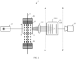
- FIG. 2
- illustrates a measurement system in accordance with a second implementation for analyzing an RF signal;
- FIGs. 3A-C
- illustrate expected light patterns at interfaces A-A' of
FIGs. 1 and2 ; - FIGs. 4A-C
- illustrate desired light patterns at interfaces B-B' of
FIGs. 1 and2 ; and - FIG. 5
- illustrates a flow chart of a method in accordance with the present disclosure for analyzing an RF signal.
-
FIG. 1 illustrates a measurement system 1 in accordance with a first implementation for analyzing an RF signal. - The system 1 comprises a
sensing medium 11, including at least one constituent being pumpable to an initial energy state, and being excitable from the initial energy state to a higher energy state by exposure to an electric and/or magnetic field. - In particular, the medium 11 may comprise an alkali metal - such as Rubidium - enclosed in an
atomic vapor cell 17, and the at least one constituent of the medium 11 may comprise atoms or ions of the alkali metal in a buffer gas. - The system 1 further comprises an
optical pump 12 configured to pump the at least one constituent of the medium 11 to the initial energy state. - The
pump 12 may comprise at least one coherent optical light source. - In particular, the
pump 12 may comprise a single coherent optical light source for pumping and readout of the medium 11. Alternatively, thepump 12 may comprise a first coherent optical light source for pumping and a second coherent optical light source for readout. For example, the respective coherent optical light source may comprise a laser. - The system 1 further comprises an
antenna 14 configured to expose the medium 11 to an electromagnetic field of the RF signal. - In particular, the
antenna 14 may comprise a waveguide such as a metallic wire (shown inFIGs. 1 and2 ) around which a near field may evolve responsive to the RF signal. Alternatively, theantenna 14 may comprise a microwave antenna (not shown) such as a reflector antenna, horn antenna, or the like. Using a single antenna ensures that a time-dependency of the RF signal under analysis is consistent across all regions of the cell. - The system 1 further comprises an
optical processor 13 configured to apply a linear transformation to light emanating from the pumpedmedium 11. That is, theoptical processor 13 is an optical element configured to manipulate a spatial distribution of the light. - In the implementation of
FIG. 1 , the light emanating from the pumpedmedium 11 may comprise a pump light transmission through the medium 11 having a cross-sectional intensity distribution depending on a frequency of the electromagnetic field of the RF signal. - The
optical processor 13 may comprise a trained artificial neural network,ANN 131, being configured to apply the linear transformation to the light emanating from the pumpedmedium 11. - An example of such an
optical processor 13 is described in "All-optical machine learning using diffractive deep neural networks" by Lin et al., Science 361, pp. 1004-1008 (2018). - The trained
ANN 131 may comprise a number ofdiffractive layers 1311 being arranged in series for traversal by the light emanating from the pumpedmedium 11. Thediffractive layers 1311 are microstructured diffraction surfaces which implement a linear transformation on the input light. - The
diffractive layers 1311 may be established by supervised learning with labelled training data, and additive manufacture, such as 3D printing. - The labelling of the training data may take into account one or more of: a desired output of the linear transformation; a focusing of the transformed light to the camera; calibration; and error correction.
- The system 1 further comprises an
optical detector 15 configured to detect an optical property of the transformed light. - The
detector 15 may comprise at least one charge-coupled device, CCD, chip extending across a cross-section of the transformed light. For example, if thedetector 15 cannot measure continuously, it is possible to use two camera chips taking turns. The detected optical property may comprise a cross-sectional intensity distribution of the transformed light. - The system 1 may further comprise a
field generator 16 configured to expose the medium 11 to a static electric or magnetic field. A strength of the generated field may define an absorption spectrum of the medium 11. - In particular, the strength of the generated field may have a gradient along a spatial dimension X of the medium 11. In
FIG. 1 , said spatial dimension X is indicated by an arrow pointing upwardly along the medium 11. - In particular, the
field generator 16 may comprise a permanent magnet. For example,FIG. 1 shows a pair of oppositely alignedpermanent magnets 16 whose respective magnetic fields tend to cancel each other out halfway of their spacing. As a result, the strength of the generated magnetic field has a gradient along the spatial dimension X of the medium 11. - A presence of such an inhomogeneous magnetic field may cause Zeeman splitting, which ensures availability of atoms, ions or point defects in an initial state for each frequency in a desired frequency range, which may be included in a microwave frequency range ranging between 300 MHz and 300 GHz, respectively.
- Zeeman splitting may refer to splitting of a spectral line, such as the initial state, into several components in the presence of a static magnetic field. Stark splitting, the electric-field analogue of
- Zeeman splitting, may refer to splitting of a spectral line into several components in the presence of a static electric field.
-
FIG. 2 illustrates a measurement system 1 in accordance with a second implementation for analyzing an RF signal. - In the alternative implementation of
FIG. 2 , the medium 11 may comprise a Nitrogen vacancy, NV, diamond, and the at least one constituent of the medium 11 may comprise point defects. In this case, the light emanating from the pumpedmedium 11 may comprise a - fluorescent - light emission of the medium 11 having a directional intensity distribution depending on the frequency of the electromagnetic field of the RF signal. - In other words, the light emission may be divergent. As such, the system 1 may further comprise an
optical lens 132 configured to collimate the light emanating from the pumped medium 11 onto theoptical processor 13. - All other elements of
FIG. 2 correspond to those already explained in connection withFIG. 1 and having same reference numerals. -
FIGs. 3A-C illustrate expected light patterns at interfaces A-A' ofFIGs. 1 and2 . -
FIG. 3A shows no RF signal at all (f = 0). -
FIG. 3B shows an expected multi-component light pattern resulting from a first exemplary RF frequency component (f = 15 GHz). -
FIG. 3C shows an expected multi-component light pattern resulting from a second exemplary RF frequency component (f = 25 GHz). - The multi-component patterns of
FIG. 3B and 3C complicate an identification of the analyzed frequency components, and this would become even more difficult when analyzing multiple frequency components. - After optical processing (i.e., transformation) of the expected light patterns of
FIG. 3 A-C , the detector images should ideally correspond to the light patterns ofFIG. 4A-C . -
FIGs. 4A-C illustrate desired light patterns at interfaces B-B' ofFIGs. 1 and2 . -
FIG. 4A shows no RF signal (f = 0), owing to a lack of frequency content. -
FIG. 4B shows a desired single-component light pattern resulting from the first exemplary RF signal (f = 15 GHz). -
FIG. 4C shows a desired single-component light pattern resulting from the second exemplary RF signal (f = 25 GHz). -
FIGs. 3A-C and 4A-C represent example light patterns that may be used as labelled training data for supervised learning. More specifically, this may involve applyingFIGs. 3A-C and similar light patterns one after another to an input layer of theANN 131, obtaining resulting output light patterns at an output layer of theANN 131, and performing a backpropagation (or similar) algorithm to train theANN 131 based on discrepancies between pairs of output light patterns and desired light patterns. -
FIG. 5 illustrates a flow chart of a method 2 in accordance with the present disclosure for analyzing an RF signal. - The method 2 comprises pumping 21 at least one constituent of a
sensing medium 11 to an initial energy state. The at least one constituent is further excitable from the initial energy state to a higher energy state by exposure to an electric and/or magnetic field. - The method 2 further comprises exposing 22 the medium 11 to an electromagnetic field of the RF signal.
- The method 2 further comprises applying 23 a linear transformation to light emanating from the pumped
medium 11. - The method 2 further comprises detecting 24 an optical property of the transformed light.
Claims (14)
- A measurement system (1) for analyzing an RF signal, comprising- a sensing medium (11), including at least one constituent- being pumpable to an initial energy state, and- being excitable from the initial energy state to a higher energy state by exposure to an electric and/or magnetic field;- an optical pump (12) configured to pump the at least one constituent of the sensing medium (11) to the initial energy state;- an antenna (14) configured to expose the sensing medium (11) to an electromagnetic field of the RF signal in order to excite it;- an optical processor (13) configured to apply a linear transformation to light emanating from the pumped sensing medium (11); and- an optical detector (15) configured to detect an optical property of the transformed light.
- The system of claim 1,
wherein the light emanating from the sensing medium (11) is pump light from the optical pump or probing light from another light source, respectively passing through or reflected by the sensing medium (11). - The system (1) of claim 1 or 2, further comprising
a field generator (16) configured to expose the medium (11) to a static electric or magnetic field, a strength of which defining an absorption spectrum of the medium (11). - The system (1) of any of the preceding claims,
the strength of the generated field having a gradient along a spatial dimension (X) of the medium (11). - The system (1) of claim 4,
the field generator (16) comprising a permanent magnet. - The system (1) of any one of the preceding claims,
the processor (13) comprising a trained artificial neural network, ANN (131), being configured to apply the linear transformation to the light emanating from the pumped medium (11). - The system (1) of claim 6,
the trained ANN (131) comprising a number of diffractive layers (1311) being arranged in series for traversal by the light emanating from the pumped medium (11). - The system (1) of claim 6 or claim 7,
the diffractive layers (1311) being established by supervised learning with labelled training data, and additive manufacture. - The system (1) of claim 8,
the labelling of the training data taking into account one or more of:- a desired output of the linear transformation;- a focusing of the transformed light to the camera;- calibration; and- error correction. - The system (1) of any one of the claims 1 to 8,the medium (11) comprising an alkali metal enclosed in an atomic vapor cell (17);the at least one constituent of the medium (11) comprising atoms or ions in a buffer gas; andthe light emanating from the pumped medium (11) comprising a light transmission through the medium (11) having a cross-sectional intensity distribution depending on a frequency of the electromagnetic field of the RF signal.
- The system (1) of any one of the claims 1 to 8,the medium (11) comprising a Nitrogen vacancy, NV, diamond;the at least one constituent of the medium (11) comprising point defects;the light emanating from the pumped medium (11) comprising a light emission of the medium (11) having a directional intensity distribution depending on the frequency of the electromagnetic field of the RF signal; andthe system (1) further comprising an optical lens (132) configured to collimate the light emanating from the pumped medium (11) onto the processor (13).
- The system (1) of any one of the preceding claims,
the pump (12) comprising at least one coherent optical light source. - The system (1) of any one of the preceding claims,the detector (15) comprising at least one charge-coupled device, CCD, chip or CMOS chip, extending across a cross-section of the transformed light; andthe detected optical property comprising a cross-sectional intensity distribution of the transformed light.
- A method (2) of analyzing an RF signal, comprising- pumping (21) at least one constituent of a sensing medium (11) to an initial energy state, the at least one constituent further being excitable from the initial energy state to a higher energy state by exposure to an electric and/or magnetic field;- exposing (22) the medium (11) to an electromagnetic field of the RF signal;- applying (23) a linear transformation to light emanating from the pumped medium (11); and- detecting (24) an optical property of the transformed light.
Priority Applications (1)
| Application Number | Priority Date | Filing Date | Title |
|---|---|---|---|
| EP22152170.1A EP4215928B1 (en) | 2022-01-19 | 2022-01-19 | Microwave signal analysis based on optical pre-processing and quantum sensing |
Applications Claiming Priority (1)
| Application Number | Priority Date | Filing Date | Title |
|---|---|---|---|
| EP22152170.1A EP4215928B1 (en) | 2022-01-19 | 2022-01-19 | Microwave signal analysis based on optical pre-processing and quantum sensing |
Publications (2)
| Publication Number | Publication Date |
|---|---|
| EP4215928A1 true EP4215928A1 (en) | 2023-07-26 |
| EP4215928B1 EP4215928B1 (en) | 2025-01-08 |
Family
ID=79830790
Family Applications (1)
| Application Number | Title | Priority Date | Filing Date |
|---|---|---|---|
| EP22152170.1A Active EP4215928B1 (en) | 2022-01-19 | 2022-01-19 | Microwave signal analysis based on optical pre-processing and quantum sensing |
Country Status (1)
| Country | Link |
|---|---|
| EP (1) | EP4215928B1 (en) |
Citations (3)
| Publication number | Priority date | Publication date | Assignee | Title |
|---|---|---|---|---|
| US3513381A (en) * | 1967-07-17 | 1970-05-19 | Varian Associates | Off-resonant light as a probe of optically pumped alkali vapors |
| EP3588117A1 (en) * | 2017-02-21 | 2020-01-01 | Sumitomo Electric Industries, Ltd. | Diamond magnetic sensor |
| EP3809145A1 (en) * | 2019-10-15 | 2021-04-21 | Rohde & Schwarz GmbH & Co. KG | System for analyzing electromagnetic radiation |
-
2022
- 2022-01-19 EP EP22152170.1A patent/EP4215928B1/en active Active
Patent Citations (3)
| Publication number | Priority date | Publication date | Assignee | Title |
|---|---|---|---|---|
| US3513381A (en) * | 1967-07-17 | 1970-05-19 | Varian Associates | Off-resonant light as a probe of optically pumped alkali vapors |
| EP3588117A1 (en) * | 2017-02-21 | 2020-01-01 | Sumitomo Electric Industries, Ltd. | Diamond magnetic sensor |
| EP3809145A1 (en) * | 2019-10-15 | 2021-04-21 | Rohde & Schwarz GmbH & Co. KG | System for analyzing electromagnetic radiation |
Non-Patent Citations (4)
| Title |
|---|
| CETINTAS MUSTAFA: "Microwave Magnetic Field Pattern Evaluation of Horn and Patch Antennas Using Cs Atomic Sensor", IEEE SENSORS JOURNAL, IEEE, USA, vol. 21, no. 7, 20 January 2021 (2021-01-20), pages 9016 - 9022, XP011842884, ISSN: 1530-437X, [retrieved on 20210304], DOI: 10.1109/JSEN.2021.3053123 * |
| LIN ET AL.: "All-optical machine learning using diffractive deep neural networks", SCIENCE, vol. 361, 2018, pages 1004 - 1008, XP055816942, DOI: 10.1126/science.aat8084 |
| LIN XING ET AL: "All-optical machine learning using diffractive deep neural networks", SCIENCE, vol. 361, no. 6406, 7 September 2018 (2018-09-07), US, pages 1004 - 1008, XP055933107, ISSN: 0036-8075, DOI: 10.1126/science.aat8084 * |
| STÜRNER FELIX M ET AL: "Compact integrated magnetometer based on nitrogen-vacancy centres in diamond", DIAMOND AND RELATED MATERIALS, vol. 93, 17 January 2019 (2019-01-17), pages 59 - 65, XP085642093, ISSN: 0925-9635, DOI: 10.1016/J.DIAMOND.2019.01.008 * |
Also Published As
| Publication number | Publication date |
|---|---|
| EP4215928B1 (en) | 2025-01-08 |
Similar Documents
| Publication | Publication Date | Title |
|---|---|---|
| CN109061295B (en) | Near-field microwave resonator resonant frequency measurement system and method | |
| KR100416245B1 (en) | Device for the optical inspection of a fluid, esqecially for hematological analyses | |
| CN115825033A (en) | A microwave reflection detection device and method based on diamond NV color center | |
| CN106646510B (en) | A first-photon laser imaging system based on photon labeling | |
| JP2010261716A (en) | Electromagnetic field measurement device | |
| CN106662485A (en) | Measuring polarization | |
| CN109253997B (en) | A Raman Tomography System Based on Frequency Modulation and Spatial Coding | |
| Altayeb et al. | TinyML gamma radiation classifier | |
| US20240175809A1 (en) | System and computer-implemented method for determining predicted component concentrations of a target mixture | |
| EP4215928B1 (en) | Microwave signal analysis based on optical pre-processing and quantum sensing | |
| Paul et al. | Continuous-wave planar laser induced fluorescence with a fast camera | |
| CN115003981A (en) | Method and system for combining OCD and light reflection | |
| CN109520983A (en) | A kind of quality evaluation method and device based on DOM | |
| GB2573410A (en) | Particle size distribution measuring device and program for particle size distribution measuring device | |
| Khansadurai et al. | Design and Optimization of Porous-Core Photonic Crystal Fiber Biosensor for Label-Free White Blood Cell Classification Using Crayfish Equivariant Simplicial Quantum Attention Networks | |
| JPS6151569A (en) | cell identification device | |
| Garcia-Caurel et al. | Experimental classification of dynamic speckle regimes: insights from controlled rotational diffuser measurements | |
| CN118883519A (en) | A fluorescence and turbidity measuring device and use method | |
| US20250198847A1 (en) | Optical module | |
| Chen et al. | Optimal probe States for single-mode quantum target detection in arbitrary object reflectivity | |
| Abramovych et al. | Application of the support vector machines method for metal analyse by an eddy current system | |
| CN120314268B (en) | Single-exposure hyperspectral imaging system and detection method based on intensity-polarization joint modulation mask | |
| CN112255201A (en) | Multi-light-path multiplexing water quality monitoring method and system, computer equipment and storage medium | |
| KR102875238B1 (en) | Surface plasmon resonance imaging apparatus and method | |
| Khajisvili et al. | 3D fluorescence spectroscopy of liquid media via internal reference method |
Legal Events
| Date | Code | Title | Description |
|---|---|---|---|
| PUAI | Public reference made under article 153(3) epc to a published international application that has entered the european phase |
Free format text: ORIGINAL CODE: 0009012 |
|
| STAA | Information on the status of an ep patent application or granted ep patent |
Free format text: STATUS: THE APPLICATION HAS BEEN PUBLISHED |
|
| STAA | Information on the status of an ep patent application or granted ep patent |
Free format text: STATUS: REQUEST FOR EXAMINATION WAS MADE |
|
| AK | Designated contracting states |
Kind code of ref document: A1 Designated state(s): AL AT BE BG CH CY CZ DE DK EE ES FI FR GB GR HR HU IE IS IT LI LT LU LV MC MK MT NL NO PL PT RO RS SE SI SK SM TR |
|
| 17P | Request for examination filed |
Effective date: 20230720 |
|
| RBV | Designated contracting states (corrected) |
Designated state(s): AL AT BE BG CH CY CZ DE DK EE ES FI FR GB GR HR HU IE IS IT LI LT LU LV MC MK MT NL NO PL PT RO RS SE SI SK SM TR |
|
| STAA | Information on the status of an ep patent application or granted ep patent |
Free format text: STATUS: EXAMINATION IS IN PROGRESS |
|
| 17Q | First examination report despatched |
Effective date: 20240326 |
|
| GRAP | Despatch of communication of intention to grant a patent |
Free format text: ORIGINAL CODE: EPIDOSNIGR1 |
|
| STAA | Information on the status of an ep patent application or granted ep patent |
Free format text: STATUS: GRANT OF PATENT IS INTENDED |
|
| RIC1 | Information provided on ipc code assigned before grant |
Ipc: G02B 27/42 20060101ALN20241007BHEP Ipc: G01R 33/26 20060101ALN20241007BHEP Ipc: G01R 33/32 20060101ALN20241007BHEP Ipc: G01R 23/17 20060101ALI20241007BHEP Ipc: G06N 3/067 20060101ALI20241007BHEP Ipc: G01R 29/08 20060101ALI20241007BHEP Ipc: G01R 33/60 20060101ALI20241007BHEP Ipc: G01R 33/44 20060101AFI20241007BHEP |
|
| INTG | Intention to grant announced |
Effective date: 20241017 |
|
| RIN1 | Information on inventor provided before grant (corrected) |
Inventor name: HO, MELVYN Inventor name: RUSTER, THOMAS Inventor name: GUEZELARSLAN, BARIS |
|
| GRAS | Grant fee paid |
Free format text: ORIGINAL CODE: EPIDOSNIGR3 |
|
| GRAA | (expected) grant |
Free format text: ORIGINAL CODE: 0009210 |
|
| STAA | Information on the status of an ep patent application or granted ep patent |
Free format text: STATUS: THE PATENT HAS BEEN GRANTED |
|
| AK | Designated contracting states |
Kind code of ref document: B1 Designated state(s): AL AT BE BG CY CZ DE DK EE ES FI FR GB GR HR HU IS IT LT LU LV MC MK MT NL NO PL PT RO RS SE SI SK SM TR |
|
| RBV | Designated contracting states (corrected) |
Designated state(s): AL AT BE BG CY CZ DE DK EE ES FI FR GB GR HR HU IS IT LT LU LV MC MK MT NL NO PL PT RO RS SE SI SK SM TR |
|
| REG | Reference to a national code |
Ref country code: GB Ref legal event code: FG4D |
|
| REG | Reference to a national code |
Ref country code: DE Ref legal event code: R096 Ref document number: 602022009445 Country of ref document: DE |
|
| P01 | Opt-out of the competence of the unified patent court (upc) registered |
Free format text: CASE NUMBER: APP_7344/2025 Effective date: 20250212 |
|
| PGFP | Annual fee paid to national office [announced via postgrant information from national office to epo] |
Ref country code: AT Payment date: 20250417 Year of fee payment: 4 |
|
| REG | Reference to a national code |
Ref country code: LT Ref legal event code: MG9D |
|
| REG | Reference to a national code |
Ref country code: NL Ref legal event code: MP Effective date: 20250108 |
|
| REG | Reference to a national code |
Ref country code: AT Ref legal event code: MK05 Ref document number: 1758663 Country of ref document: AT Kind code of ref document: T Effective date: 20250108 |
|
| PG25 | Lapsed in a contracting state [announced via postgrant information from national office to epo] |
Ref country code: NL Free format text: LAPSE BECAUSE OF FAILURE TO SUBMIT A TRANSLATION OF THE DESCRIPTION OR TO PAY THE FEE WITHIN THE PRESCRIBED TIME-LIMIT Effective date: 20250108 |
|
| PG25 | Lapsed in a contracting state [announced via postgrant information from national office to epo] |
Ref country code: RS Free format text: LAPSE BECAUSE OF FAILURE TO SUBMIT A TRANSLATION OF THE DESCRIPTION OR TO PAY THE FEE WITHIN THE PRESCRIBED TIME-LIMIT Effective date: 20250408 |
|
| PG25 | Lapsed in a contracting state [announced via postgrant information from national office to epo] |
Ref country code: FI Free format text: LAPSE BECAUSE OF FAILURE TO SUBMIT A TRANSLATION OF THE DESCRIPTION OR TO PAY THE FEE WITHIN THE PRESCRIBED TIME-LIMIT Effective date: 20250108 |
|
| PG25 | Lapsed in a contracting state [announced via postgrant information from national office to epo] |
Ref country code: PL Free format text: LAPSE BECAUSE OF FAILURE TO SUBMIT A TRANSLATION OF THE DESCRIPTION OR TO PAY THE FEE WITHIN THE PRESCRIBED TIME-LIMIT Effective date: 20250108 |
|
| PG25 | Lapsed in a contracting state [announced via postgrant information from national office to epo] |
Ref country code: ES Free format text: LAPSE BECAUSE OF FAILURE TO SUBMIT A TRANSLATION OF THE DESCRIPTION OR TO PAY THE FEE WITHIN THE PRESCRIBED TIME-LIMIT Effective date: 20250108 |
|
| PG25 | Lapsed in a contracting state [announced via postgrant information from national office to epo] |
Ref country code: NO Free format text: LAPSE BECAUSE OF FAILURE TO SUBMIT A TRANSLATION OF THE DESCRIPTION OR TO PAY THE FEE WITHIN THE PRESCRIBED TIME-LIMIT Effective date: 20250408 Ref country code: IS Free format text: LAPSE BECAUSE OF FAILURE TO SUBMIT A TRANSLATION OF THE DESCRIPTION OR TO PAY THE FEE WITHIN THE PRESCRIBED TIME-LIMIT Effective date: 20250508 |
|
| PG25 | Lapsed in a contracting state [announced via postgrant information from national office to epo] |
Ref country code: HR Free format text: LAPSE BECAUSE OF FAILURE TO SUBMIT A TRANSLATION OF THE DESCRIPTION OR TO PAY THE FEE WITHIN THE PRESCRIBED TIME-LIMIT Effective date: 20250108 |
|
| PG25 | Lapsed in a contracting state [announced via postgrant information from national office to epo] |
Ref country code: LV Free format text: LAPSE BECAUSE OF FAILURE TO SUBMIT A TRANSLATION OF THE DESCRIPTION OR TO PAY THE FEE WITHIN THE PRESCRIBED TIME-LIMIT Effective date: 20250108 Ref country code: PT Free format text: LAPSE BECAUSE OF FAILURE TO SUBMIT A TRANSLATION OF THE DESCRIPTION OR TO PAY THE FEE WITHIN THE PRESCRIBED TIME-LIMIT Effective date: 20250508 |
|
| PG25 | Lapsed in a contracting state [announced via postgrant information from national office to epo] |
Ref country code: GR Free format text: LAPSE BECAUSE OF FAILURE TO SUBMIT A TRANSLATION OF THE DESCRIPTION OR TO PAY THE FEE WITHIN THE PRESCRIBED TIME-LIMIT Effective date: 20250409 Ref country code: BG Free format text: LAPSE BECAUSE OF FAILURE TO SUBMIT A TRANSLATION OF THE DESCRIPTION OR TO PAY THE FEE WITHIN THE PRESCRIBED TIME-LIMIT Effective date: 20250108 |
|
| PG25 | Lapsed in a contracting state [announced via postgrant information from national office to epo] |
Ref country code: AT Free format text: LAPSE BECAUSE OF FAILURE TO SUBMIT A TRANSLATION OF THE DESCRIPTION OR TO PAY THE FEE WITHIN THE PRESCRIBED TIME-LIMIT Effective date: 20250108 |
|
| PG25 | Lapsed in a contracting state [announced via postgrant information from national office to epo] |
Ref country code: SE Free format text: LAPSE BECAUSE OF FAILURE TO SUBMIT A TRANSLATION OF THE DESCRIPTION OR TO PAY THE FEE WITHIN THE PRESCRIBED TIME-LIMIT Effective date: 20250108 |
|
| PG25 | Lapsed in a contracting state [announced via postgrant information from national office to epo] |
Ref country code: LU Free format text: LAPSE BECAUSE OF NON-PAYMENT OF DUE FEES Effective date: 20250119 |
|
| PG25 | Lapsed in a contracting state [announced via postgrant information from national office to epo] |
Ref country code: SM Free format text: LAPSE BECAUSE OF FAILURE TO SUBMIT A TRANSLATION OF THE DESCRIPTION OR TO PAY THE FEE WITHIN THE PRESCRIBED TIME-LIMIT Effective date: 20250108 |
|
| REG | Reference to a national code |
Ref country code: DE Ref legal event code: R097 Ref document number: 602022009445 Country of ref document: DE |
|
| PG25 | Lapsed in a contracting state [announced via postgrant information from national office to epo] |
Ref country code: DK Free format text: LAPSE BECAUSE OF FAILURE TO SUBMIT A TRANSLATION OF THE DESCRIPTION OR TO PAY THE FEE WITHIN THE PRESCRIBED TIME-LIMIT Effective date: 20250108 |
|
| PG25 | Lapsed in a contracting state [announced via postgrant information from national office to epo] |
Ref country code: MC Free format text: LAPSE BECAUSE OF FAILURE TO SUBMIT A TRANSLATION OF THE DESCRIPTION OR TO PAY THE FEE WITHIN THE PRESCRIBED TIME-LIMIT Effective date: 20250108 |
|
| PG25 | Lapsed in a contracting state [announced via postgrant information from national office to epo] |
Ref country code: BE Free format text: LAPSE BECAUSE OF NON-PAYMENT OF DUE FEES Effective date: 20250131 |
|
| PG25 | Lapsed in a contracting state [announced via postgrant information from national office to epo] |
Ref country code: CZ Free format text: LAPSE BECAUSE OF FAILURE TO SUBMIT A TRANSLATION OF THE DESCRIPTION OR TO PAY THE FEE WITHIN THE PRESCRIBED TIME-LIMIT Effective date: 20250108 Ref country code: EE Free format text: LAPSE BECAUSE OF FAILURE TO SUBMIT A TRANSLATION OF THE DESCRIPTION OR TO PAY THE FEE WITHIN THE PRESCRIBED TIME-LIMIT Effective date: 20250108 |
|
| REG | Reference to a national code |
Ref country code: BE Ref legal event code: MM Effective date: 20250131 |
|
| PG25 | Lapsed in a contracting state [announced via postgrant information from national office to epo] |
Ref country code: RO Free format text: LAPSE BECAUSE OF FAILURE TO SUBMIT A TRANSLATION OF THE DESCRIPTION OR TO PAY THE FEE WITHIN THE PRESCRIBED TIME-LIMIT Effective date: 20250108 |
|
| PG25 | Lapsed in a contracting state [announced via postgrant information from national office to epo] |
Ref country code: SK Free format text: LAPSE BECAUSE OF FAILURE TO SUBMIT A TRANSLATION OF THE DESCRIPTION OR TO PAY THE FEE WITHIN THE PRESCRIBED TIME-LIMIT Effective date: 20250108 |
|
| PLBE | No opposition filed within time limit |
Free format text: ORIGINAL CODE: 0009261 |
|
| STAA | Information on the status of an ep patent application or granted ep patent |
Free format text: STATUS: NO OPPOSITION FILED WITHIN TIME LIMIT |
|
| 26N | No opposition filed |
Effective date: 20251009 |
|
| PG25 | Lapsed in a contracting state [announced via postgrant information from national office to epo] |
Ref country code: IT Free format text: LAPSE BECAUSE OF FAILURE TO SUBMIT A TRANSLATION OF THE DESCRIPTION OR TO PAY THE FEE WITHIN THE PRESCRIBED TIME-LIMIT Effective date: 20250108 |
|
| PGFP | Annual fee paid to national office [announced via postgrant information from national office to epo] |
Ref country code: GB Payment date: 20260122 Year of fee payment: 5 |
|
| PGFP | Annual fee paid to national office [announced via postgrant information from national office to epo] |
Ref country code: DE Payment date: 20260120 Year of fee payment: 5 |
|
| PGFP | Annual fee paid to national office [announced via postgrant information from national office to epo] |
Ref country code: FR Payment date: 20260128 Year of fee payment: 5 |
|
| PG25 | Lapsed in a contracting state [announced via postgrant information from national office to epo] |
Ref country code: CY Free format text: LAPSE BECAUSE OF FAILURE TO SUBMIT A TRANSLATION OF THE DESCRIPTION OR TO PAY THE FEE WITHIN THE PRESCRIBED TIME-LIMIT Effective date: 20250108 |
|
| PG25 | Lapsed in a contracting state [announced via postgrant information from national office to epo] |
Ref country code: TR Free format text: LAPSE BECAUSE OF FAILURE TO SUBMIT A TRANSLATION OF THE DESCRIPTION OR TO PAY THE FEE WITHIN THE PRESCRIBED TIME-LIMIT Effective date: 20250108 |
|
| PG25 | Lapsed in a contracting state [announced via postgrant information from national office to epo] |
Ref country code: LT Free format text: LAPSE BECAUSE OF FAILURE TO SUBMIT A TRANSLATION OF THE DESCRIPTION OR TO PAY THE FEE WITHIN THE PRESCRIBED TIME-LIMIT Effective date: 20250108 |