EP4215926A1 - Microwave signal analysis based on beam-scanned quantum sensor - Google Patents
Microwave signal analysis based on beam-scanned quantum sensor Download PDFInfo
- Publication number
- EP4215926A1 EP4215926A1 EP22152165.1A EP22152165A EP4215926A1 EP 4215926 A1 EP4215926 A1 EP 4215926A1 EP 22152165 A EP22152165 A EP 22152165A EP 4215926 A1 EP4215926 A1 EP 4215926A1
- Authority
- EP
- European Patent Office
- Prior art keywords
- medium
- light
- optical
- pump
- signal
- Prior art date
- Legal status (The legal status is an assumption and is not a legal conclusion. Google has not performed a legal analysis and makes no representation as to the accuracy of the status listed.)
- Pending
Links
Images


Classifications
-
- G—PHYSICS
- G01—MEASURING; TESTING
- G01R—MEASURING ELECTRIC VARIABLES; MEASURING MAGNETIC VARIABLES
- G01R29/00—Arrangements for measuring or indicating electric quantities not covered by groups G01R19/00 - G01R27/00
- G01R29/08—Measuring electromagnetic field characteristics
- G01R29/0864—Measuring electromagnetic field characteristics characterised by constructional or functional features
- G01R29/0878—Sensors; antennas; probes; detectors
- G01R29/0885—Sensors; antennas; probes; detectors using optical probes, e.g. electro-optical, luminescent, glow discharge, or optical interferometers
-
- G—PHYSICS
- G01—MEASURING; TESTING
- G01R—MEASURING ELECTRIC VARIABLES; MEASURING MAGNETIC VARIABLES
- G01R33/00—Arrangements or instruments for measuring magnetic variables
- G01R33/02—Measuring direction or magnitude of magnetic fields or magnetic flux
- G01R33/032—Measuring direction or magnitude of magnetic fields or magnetic flux using magneto-optic devices, e.g. Faraday or Cotton-Mouton effect
-
- G—PHYSICS
- G01—MEASURING; TESTING
- G01R—MEASURING ELECTRIC VARIABLES; MEASURING MAGNETIC VARIABLES
- G01R33/00—Arrangements or instruments for measuring magnetic variables
- G01R33/20—Arrangements or instruments for measuring magnetic variables involving magnetic resonance
- G01R33/24—Arrangements or instruments for measuring magnetic variables involving magnetic resonance for measuring direction or magnitude of magnetic fields or magnetic flux
- G01R33/26—Arrangements or instruments for measuring magnetic variables involving magnetic resonance for measuring direction or magnitude of magnetic fields or magnetic flux using optical pumping
Definitions
- the present disclosure relates to signal analysis in microwave communication, and in particular to a measurement system for real-time analysis of radio frequency (RF) signals and a corresponding method.
- RF radio frequency
- Atom-based quantum effects may be used in developing quantum sensors for various physical quantities, as is known in the art.
- Detection of microwave signals based on quantum sensors such as atomic vapor cells commonly involves a pulsed readout, wherein a laser beam is repeatedly turned off and on for pumping and readout of the atomic vapor. In such detection schemes, ongoing laser operation inhibits microwave detection, resulting in intermittent detection.
- a first aspect of the present disclosure relates to a measurement system for analyzing an RF signal.
- the system comprises a sensing medium, including at least one constituent being which is pumped to an initial energy state, and being excitable from the initial energy state to a higher energy state by exposure to an electric and/or magnetic field.
- the system further comprises an optical pump configured to pump the at least one constituent of the medium to the initial energy state.
- the system further comprises an antenna configured to expose the medium to an electromagnetic field of the RF signal.
- the system further comprises an optical processor configured to displace a probing light (which may be identical to the pump light or not) transversely along a spatial dimension of the medium in accordance with a displacement cycle.
- the system further comprises an optical detector configured to (preferably continuously) detect an optical property of light emanating from the pumped medium, as a result of the probing light.
- the system may further comprise a field generator configured to expose the medium to a static electric or magnetic field, a strength of which may define an absorption spectrum of the medium.
- the strength of the generated field may have a gradient along a spatial dimension of the medium.
- the field generator may comprise a permanent magnet.
- the optical processor may comprise an acousto-optic deflector, AOD, for diffracting the generated light along the spatial dimension of the medium.
- a diffraction angle of the diffracted light may vary over the displacement cycle in accordance with a linear transverse displacement of the pump light along the spatial dimension of the medium.
- An optical lens may be provided, configured to collimate a higher order of diffraction of the diffracted light onto the medium. Furthermore, the optical lens may be arranged to transform the diffraction angle of the AOD to a displacement along the spatial dimension of the medium.
- the optical processor may further comprise a blocker for absorbing a zeroth order of diffraction of the diffracted light.
- the displacement cycle may have a period in the order of microseconds to milliseconds.
- the medium may comprise an alkali metal enclosed in an atomic vapor cell.
- the at least one constituent of the medium may comprise atoms or ions in a buffer gas.
- the light emanating from the pumped medium may comprise a pump light transmission through the medium having a cross-sectional intensity distribution depending on a frequency of the electromagnetic field of the RF signal.
- the medium may comprise a Nitrogen vacancy, NV, diamond.
- the at least one constituent of the medium may comprise point defects.
- the light emanating from the pumped medium may comprise a light emission of the medium having a directional intensity distribution depending on the frequency of the electromagnetic field of the RF signal.
- the pump may comprise at least one coherent optical light source.
- the detector may comprise at least one charge-coupled device, CCD, chip extending across a cross-section of the light emanating from the pumped medium.
- the detected optical property may comprise a cross-sectional intensity distribution of the light emanating from the pumped medium.
- the system may further comprise a digital processor configured to reconstruct the RF signal in real-time in dependence of the detected optical property.
- a second aspect of the present disclosure relates to a method of analyzing an RF signal.
- the method comprises pumping at least one constituent of a sensing medium to an initial energy state.
- the at least one constituent is further excitable from the initial energy state to a higher energy state by exposure to an electric and/or magnetic field.
- the method further comprises exposing the medium to an electromagnetic field of the RF signal.
- the method further comprises displacing the pump light transversely along a spatial dimension of the medium in accordance with a displacement cycle.
- the method further comprises continuously detecting an optical property of light emanating from the pumped medium.
- the present disclosure provides a measurement system for analyzing RF/microwave signals that avoids intermittence of detection by a cyclic transverse displacement of a laser beam along a spatial dimension of a sensing medium.
- the direction of the field gradient of the invention is preferably different from the sweep direction, such that the entire frequency range can be detected at the same time.
- a superior dynamic range or sensitivity may be achieved, in particular by intensity modulation of the laser beam.
- FIG. 1 illustrates a measurement system 1 in accordance with the present disclosure for analyzing an RF signal.
- a case is shown where the laser is displaced along an (optional) field gradient. While this might be a useful use case, a real-time spectrum analysis scheme preferably has a gradient direction orthogonal to the sweep direction of the laser. Sweeping of the laser beam along a spatial axis can also be applied without a field gradient being present gradient at all (to e.g. get real-time field detection of a single MW frequency).
- the system 1 comprises a sensing medium 11, including at least one constituent optically pumped to an initial energy state, and being excitable from the initial energy state to a higher energy state by exposure to an electric and/or magnetic field (which is the field of a RF signal to be analysed).
- the medium 11 may comprise an alkali metal enclosed in an atomic vapor cell 17, and the at least one constituent of the medium 11 may comprise atoms or ions in a buffer gas.
- the medium 11 may comprise a Nitrogen vacancy, NV, diamond, and the at least one constituent of the medium 11 may comprise point defects.
- the system 1 further comprises an optical pump 12 configured to pump the at least one constituent of the medium 11 to the initial energy state.
- the pump 12 may comprise at least one coherent optical light source.
- the pump 12 may comprise a single coherent optical light source for pumping and optionally also the readout of the medium 11.
- the pump 12 may comprise a first coherent optical light source for pumping and a second coherent optical light source for readout (probing).
- the respective coherent optical light source may comprise a laser.
- the system 1 further comprises an antenna 14 configured to expose the medium 11 to an electromagnetic field of the RF signal.
- the antenna 14 may comprise a waveguide such as a metallic wire (shown in FIG. 1 ) around which a near field may evolve responsive to the RF signal.
- the antenna 14 may comprise a microwave antenna (not shown) such as a reflector antenna, horn antenna, or the like. Using a single antenna ensures that a time-dependency of the RF signal under analysis is consistent across all regions of the cell.
- the system 1 further comprises an optical processor 13 configured to displace the pump or the probing light transversely along a spatial dimension X of the medium 11 in accordance with a displacement cycle.
- the displacement cycle may have a period T in the order of microseconds to milliseconds (see FIG. 2 for details).
- the optical processor 13 may comprise an acousto-optic deflector, AOD 131, for diffracting the generated light along the spatial dimension X of the medium 11.
- AOD 131 acousto-optic deflector
- An AOD as used herein may refer to a Bragg cell, i.e., an optically transparent element configured to diffract incident light using an acousto-optic effect.
- a piezoelectric transducer driven by an oscillating electric signal may give rise to sound waves of wavelength ⁇ that modulate an index of refraction n of a crystal material such as quartz.
- Incident light of wavelength ⁇ in vacuum scatters off the resulting periodic index modulation, giving rise to diffraction.
- An optical lens 132 at distance D may be configured to collimate a higher order of diffraction of the diffracted light onto the medium 11.
- a further purpose of the optical lens is to transform the angle into a displacement. It is true that the lens may also collimate a focused beam, or focus a collimated beam. In order to compensate for this effect, an additional lens may be provided (e.g. before the AOD).
- the optical processor 13 may further comprise a sweep/scan controller 134 configured to control the AOD 131 in such a way that the pump or the probing light beam scans the medium 11 linearly with respect to its spatial dimension X (see description of FIG. 2 for details).
- a sweep/scan controller 134 configured to control the AOD 131 in such a way that the pump or the probing light beam scans the medium 11 linearly with respect to its spatial dimension X (see description of FIG. 2 for details).
- the system 1 further comprises an optical detector 15 configured to continuously detect an optical property of light emanating from the pumped medium 11. This is typically the probing light going through to reflected by sensing medium, the optical characteristics of the sensing medium (as detected by the probing light) being dependent on the e.g. the field strength of the RF signal to be analysed at a given location in the sensing medium.
- an optical detector 15 configured to continuously detect an optical property of light emanating from the pumped medium 11. This is typically the probing light going through to reflected by sensing medium, the optical characteristics of the sensing medium (as detected by the probing light) being dependent on the e.g. the field strength of the RF signal to be analysed at a given location in the sensing medium.
- the detector 15 may comprise at least one charge-coupled device, CCD, chip extending across a cross-section of the light emanating from the pumped medium 11.
- CCD charge-coupled device
- the detected optical property may comprise a cross-sectional intensity distribution of the light emanating from the pumped medium 11.
- the light emanating from the pumped medium 11 may comprise a probing(readout light) light transmission through the medium 11 having a cross-sectional intensity distribution depending on a frequency and filed strength of the electromagnetic field of the RF signal.
- the light emanating from the pumped medium 11 may comprise a light emission of the medium 11 having a directional intensity distribution depending on the frequency of the electromagnetic field of the RF signal.
- a pulsed measurement is performed in each section of the medium 11. Depending on a displacement X(t) of the pump light the measurement sequence starts at a different time t. While a particular section is being pumped/read out, there are still other sections interacting with the electromagnetic field of the RF signal.
- system 1 may further comprise a digital processor 18 configured to reconstruct the RF signal in real-time in dependence of the detected optical property.
- the system 1 may further comprise a field generator 16 configured to expose the medium 11 to a static electric or magnetic field.
- a strength of the generated field may define an absorption spectrum of the medium 11.
- the strength of the generated field may have a gradient along a spatial dimension X of the medium 11.
- the field generator 16 may comprise a permanent magnet.
- FIG. 1 shows a pair of oppositely aligned permanent magnets 16 whose respective magnetic fields tend to cancel each other out halfway of their spacing.
- the strength of the generated magnetic field has a gradient along the spatial dimension X of the medium 11.
- a presence of such an inhomogeneous magnetic field may cause Zeeman splitting, which ensures availability of atoms, ions or point defects in an initial state for each frequency in a desired frequency range, which may be included in a microwave frequency range ranging between 300 MHz and 300 GHz, respectively.
- Zeeman splitting may refer to splitting of a spectral line, such as the initial state, into several components in the presence of a static magnetic field.
- Stark splitting the electric-field analogue of Zeeman splitting, may refer to splitting of a spectral line into several components in the presence of a static electric field.
- FIG. 2 illustrates a periodic displacement cycle in accordance with the present disclosure of the system 1 of FIG. 1 .
- the example shows multiple displacement cycles of period T .
- the transverse displacement X of the pump light evolves linearly over time T, in accordance with the above mathematical description.
- FIG. 3 illustrates a flow chart of a method 2 in accordance with the present disclosure for analyzing an RF signal.
- the method 2 comprises pumping 21 at least one constituent of a sensing medium 11 to an initial energy state.
- the at least one constituent is further excitable from the initial energy state to a higher energy state by exposure to an electric and/or magnetic field.
- the method 2 further comprises exposing 22 the medium 11 to an electromagnetic field of the RF signal.
- the method 2 further comprises displacing 23 the pump 12 light transversely along a spatial dimension X of the medium 11 in accordance with a displacement cycle.
- the method 2 further comprises continuously detecting 24 an optical property of light emanating from the pumped medium 11.
Landscapes
- Physics & Mathematics (AREA)
- General Physics & Mathematics (AREA)
- Electromagnetism (AREA)
- Engineering & Computer Science (AREA)
- Power Engineering (AREA)
- Condensed Matter Physics & Semiconductors (AREA)
- Investigating Or Analysing Materials By Optical Means (AREA)
Abstract
Description
- The present disclosure relates to signal analysis in microwave communication, and in particular to a measurement system for real-time analysis of radio frequency (RF) signals and a corresponding method.
- Atom-based quantum effects may be used in developing quantum sensors for various physical quantities, as is known in the art.
- Detection of microwave signals based on quantum sensors such as atomic vapor cells commonly involves a pulsed readout, wherein a laser beam is repeatedly turned off and on for pumping and readout of the atomic vapor. In such detection schemes, ongoing laser operation inhibits microwave detection, resulting in intermittent detection.
- The present disclosure therefore strives to improve an RF signal analysis of the background art. The objective is achieved by the embodiments as defined by the appended independent claims. Preferred embodiments are set forth in the dependent claims and in the following description and drawings.
- A first aspect of the present disclosure relates to a measurement system for analyzing an RF signal. The system comprises a sensing medium, including at least one constituent being which is pumped to an initial energy state, and being excitable from the initial energy state to a higher energy state by exposure to an electric and/or magnetic field. The system further comprises an optical pump configured to pump the at least one constituent of the medium to the initial energy state. The system further comprises an antenna configured to expose the medium to an electromagnetic field of the RF signal. The system further comprises an optical processor configured to displace a probing light (which may be identical to the pump light or not) transversely along a spatial dimension of the medium in accordance with a displacement cycle. The system further comprises an optical detector configured to (preferably continuously) detect an optical property of light emanating from the pumped medium, as a result of the probing light.
- The system may further comprise a field generator configured to expose the medium to a static electric or magnetic field, a strength of which may define an absorption spectrum of the medium.
- The strength of the generated field may have a gradient along a spatial dimension of the medium.
- The field generator may comprise a permanent magnet.
- The optical processor may comprise an acousto-optic deflector, AOD, for diffracting the generated light along the spatial dimension of the medium. A diffraction angle of the diffracted light may vary over the displacement cycle in accordance with a linear transverse displacement of the pump light along the spatial dimension of the medium. An optical lens may be provided, configured to collimate a higher order of diffraction of the diffracted light onto the medium. Furthermore, the optical lens may be arranged to transform the diffraction angle of the AOD to a displacement along the spatial dimension of the medium.
- The optical processor may further comprise a blocker for absorbing a zeroth order of diffraction of the diffracted light.
- The displacement cycle may have a period in the order of microseconds to milliseconds.
- The medium may comprise an alkali metal enclosed in an atomic vapor cell. The at least one constituent of the medium may comprise atoms or ions in a buffer gas. The light emanating from the pumped medium may comprise a pump light transmission through the medium having a cross-sectional intensity distribution depending on a frequency of the electromagnetic field of the RF signal. The medium may comprise a Nitrogen vacancy, NV, diamond. The at least one constituent of the medium may comprise point defects. The light emanating from the pumped medium may comprise a light emission of the medium having a directional intensity distribution depending on the frequency of the electromagnetic field of the RF signal.
- The pump may comprise at least one coherent optical light source.
- The detector may comprise at least one charge-coupled device, CCD, chip extending across a cross-section of the light emanating from the pumped medium. The detected optical property may comprise a cross-sectional intensity distribution of the light emanating from the pumped medium.
- The system may further comprise a digital processor configured to reconstruct the RF signal in real-time in dependence of the detected optical property.
- A second aspect of the present disclosure relates to a method of analyzing an RF signal. The method comprises pumping at least one constituent of a sensing medium to an initial energy state. The at least one constituent is further excitable from the initial energy state to a higher energy state by exposure to an electric and/or magnetic field. The method further comprises exposing the medium to an electromagnetic field of the RF signal. The method further comprises displacing the pump light transversely along a spatial dimension of the medium in accordance with a displacement cycle. The method further comprises continuously detecting an optical property of light emanating from the pumped medium.
- The present disclosure provides a measurement system for analyzing RF/microwave signals that avoids intermittence of detection by a cyclic transverse displacement of a laser beam along a spatial dimension of a sensing medium.
- In other words, it is possible to sweep the position of the laser beam across the sensing medium (beam scanning) such that the medium is pumped and read-out somewhere without interruption, and at the same time interacts with the RF/microwave signal elsewhere.
- For spectrum analysis, it is possible to sweep the position of the laser beam across a field gradient. This is easier to implement compared to classical spectrum analysis wherein a magnetic/electric field is varied over time to measure a spectrum. Note that, for real-time spectrum analysis, the direction of the field gradient of the invention is preferably different from the sweep direction, such that the entire frequency range can be detected at the same time.
- Compared to classical RF/microwave detection schemes, a superior dynamic range or sensitivity may be achieved, in particular by intensity modulation of the laser beam.
- The technical effects and advantages described above in relation with the measurement system for analyzing an RF signal equally apply to the method of analyzing an RF signal having corresponding features.
- The above-described aspects and implementations will now be explained with reference to the accompanying drawings, in which the same or similar reference numerals designate the same or similar elements.
- The features of these aspects and implementations may be combined with each other unless specifically stated otherwise.
- The drawings are to be regarded as being schematic representations, and elements illustrated in the drawings are not necessarily shown to scale. Rather, the various elements are represented such that their function and general purpose become apparent to those skilled in the art.
- FIG. 1
- illustrates a measurement system in accordance with the present disclosure for analyzing an RF signal;
- FIG. 2
- illustrates a periodic displacement cycle in accordance with the present disclosure of the system 1 of
FIG. 1 ; and - FIG. 3
- illustrates a flow chart of a method in accordance with the present disclosure for analyzing an RF signal.
-
FIG. 1 illustrates a measurement system 1 in accordance with the present disclosure for analyzing an RF signal. - In
Fig 1 , a case is shown where the laser is displaced along an (optional) field gradient. While this might be a useful use case, a real-time spectrum analysis scheme preferably has a gradient direction orthogonal to the sweep direction of the laser. Sweeping of the laser beam along a spatial axis can also be applied without a field gradient being present gradient at all (to e.g. get real-time field detection of a single MW frequency). - The system 1 comprises a
sensing medium 11, including at least one constituent optically pumped to an initial energy state, and being excitable from the initial energy state to a higher energy state by exposure to an electric and/or magnetic field (which is the field of a RF signal to be analysed). - In particular, the medium 11 may comprise an alkali metal enclosed in an
atomic vapor cell 17, and the at least one constituent of the medium 11 may comprise atoms or ions in a buffer gas. - The buffer gas ensures that the atoms/ions remain in a respective section of the
cell 17 during a displacement cycle. According to an alternative implementation (not shown), the medium 11 may comprise a Nitrogen vacancy, NV, diamond, and the at least one constituent of the medium 11 may comprise point defects. - The system 1 further comprises an
optical pump 12 configured to pump the at least one constituent of the medium 11 to the initial energy state. - The
pump 12 may comprise at least one coherent optical light source. - In particular, the
pump 12 may comprise a single coherent optical light source for pumping and optionally also the readout of the medium 11. Alternatively, thepump 12 may comprise a first coherent optical light source for pumping and a second coherent optical light source for readout (probing). For example, the respective coherent optical light source may comprise a laser. - The system 1 further comprises an
antenna 14 configured to expose the medium 11 to an electromagnetic field of the RF signal. - In particular, the
antenna 14 may comprise a waveguide such as a metallic wire (shown inFIG. 1 ) around which a near field may evolve responsive to the RF signal. Alternatively, theantenna 14 may comprise a microwave antenna (not shown) such as a reflector antenna, horn antenna, or the like. Using a single antenna ensures that a time-dependency of the RF signal under analysis is consistent across all regions of the cell. - The system 1 further comprises an
optical processor 13 configured to displace the pump or the probing light transversely along a spatial dimension X of the medium 11 in accordance with a displacement cycle. - In particular, the displacement cycle may have a period T in the order of microseconds to milliseconds (see
FIG. 2 for details). - For example, the
optical processor 13 may comprise an acousto-optic deflector,AOD 131, for diffracting the generated light along the spatial dimension X of the medium 11. InFIG. 1 , said spatial dimension X is indicated by an arrow pointing upwardly along the medium 11. - An AOD as used herein may refer to a Bragg cell, i.e., an optically transparent element configured to diffract incident light using an acousto-optic effect. For example, a piezoelectric transducer driven by an oscillating electric signal may give rise to sound waves of wavelength Λ that modulate an index of refraction n of a crystal material such as quartz. Incident light of wavelength λ in vacuum scatters off the resulting periodic index modulation, giving rise to diffraction.
- An
optical lens 132 at distance D may be configured to collimate a higher order of diffraction of the diffracted light onto the medium 11. In particular, the higher order of diffraction relates to the m = +1 diffraction order (seeFIG. 2 below for details). A further purpose of the optical lens is to transform the angle into a displacement. It is true that the lens may also collimate a focused beam, or focus a collimated beam. In order to compensate for this effect, an additional lens may be provided (e.g. before the AOD). - The
optical processor 13 may further comprise ablocker 133 for absorbing a zeroth order (m = 0) of diffraction of the diffracted light. - The
optical processor 13 may further comprise a sweep/scan controller 134 configured to control theAOD 131 in such a way that the pump or the probing light beam scans the medium 11 linearly with respect to its spatial dimension X (see description ofFIG. 2 for details). - The system 1 further comprises an
optical detector 15 configured to continuously detect an optical property of light emanating from the pumpedmedium 11. This is typically the probing light going through to reflected by sensing medium, the optical characteristics of the sensing medium (as detected by the probing light) being dependent on the e.g. the field strength of the RF signal to be analysed at a given location in the sensing medium. - In particular, the
detector 15 may comprise at least one charge-coupled device, CCD, chip extending across a cross-section of the light emanating from the pumpedmedium 11. For example, if thedetector 15 cannot measure continuously, it is possible to use two camera chips taking turns. The detected optical property may comprise a cross-sectional intensity distribution of the light emanating from the pumpedmedium 11. - The light emanating from the pumped
medium 11 may comprise a probing(readout light) light transmission through the medium 11 having a cross-sectional intensity distribution depending on a frequency and filed strength of the electromagnetic field of the RF signal. - According to the above-mentioned alternative implementation (not shown), the light emanating from the pumped
medium 11 may comprise a light emission of the medium 11 having a directional intensity distribution depending on the frequency of the electromagnetic field of the RF signal. - In each section of the medium 11, a pulsed measurement is performed. Depending on a displacement X(t) of the pump light the measurement sequence starts at a different time t. While a particular section is being pumped/read out, there are still other sections interacting with the electromagnetic field of the RF signal.
- From the detected optical property across all sections of the medium 11, a real-time measurement of the microwave is performed.
- To this end, the system 1 may further comprise a
digital processor 18 configured to reconstruct the RF signal in real-time in dependence of the detected optical property. - The system 1 may further comprise a
field generator 16 configured to expose the medium 11 to a static electric or magnetic field. A strength of the generated field may define an absorption spectrum of the medium 11. - In particular, the strength of the generated field may have a gradient along a spatial dimension X of the medium 11.
- In particular, the
field generator 16 may comprise a permanent magnet. For example,FIG. 1 shows a pair of oppositely alignedpermanent magnets 16 whose respective magnetic fields tend to cancel each other out halfway of their spacing. As a result, the strength of the generated magnetic field has a gradient along the spatial dimension X of the medium 11. - A presence of such an inhomogeneous magnetic field may cause Zeeman splitting, which ensures availability of atoms, ions or point defects in an initial state for each frequency in a desired frequency range, which may be included in a microwave frequency range ranging between 300 MHz and 300 GHz, respectively.
- Zeeman splitting may refer to splitting of a spectral line, such as the initial state, into several components in the presence of a static magnetic field. Stark splitting, the electric-field analogue of Zeeman splitting, may refer to splitting of a spectral line into several components in the presence of a static electric field.
-
FIG. 2 illustrates a periodic displacement cycle in accordance with the present disclosure of the system 1 ofFIG. 1 . - Given an incidence of light at Bragg angle θin from the perpendicular of the sound wave's propagation (note the angle of inclination of the
AOD 131 inFIG. 1 ),
AOD 131 where an order m = ..., -2, -1, 0, +1, +2, ... of diffraction (or diffracted beam) occurs at each angle θout from the perpendicular of the sound wave's propagation that satisfies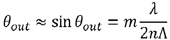
- Diffraction from a sinusoidal modulation in a thin crystal primarily results in the m = -1, 0, +1 diffraction orders.
FIG. 1 shows a diffraction order of m = +1 varying in diffraction angle α, and a diffraction order of m = 0 (directed horizontally inFIG. 1 ). - A diffraction angle α = θ out,m=+1 - θ out,m=0 of the diffracted light may be designed to vary over the displacement cycle in accordance with a linear transverse displacement of the pump light along the spatial dimension X of the medium 11. That is, by appropriate control of the diffraction angle α (or more specifically the sound wavelength Λ) over time T, a linearly evolving transverse displacement X of the pump light may be achieved, with respect to the displacement X = 0 of the zeroth order of diffraction, i.e., m = 0:


- This approximation applies for small angles α and θ out. An example of such a linearly evolving displacement X of the pump light over time T may be taken from
FIG. 2 . - The example shows multiple displacement cycles of period T. During each displacement cycle, the transverse displacement X of the pump light evolves linearly over time T, in accordance with the above mathematical description.
- Continuously, there is a transverse displacement X(T) where the medium 11 is pumped and read out while the rest of the medium 11 may interact with the RF/microwave signal.
- At the end of the sweep/scan/period, the pump beam may be turned off, reset to its initial position X = 0, and turned on again.
-
FIG. 3 illustrates a flow chart of a method 2 in accordance with the present disclosure for analyzing an RF signal. - The method 2 comprises pumping 21 at least one constituent of a
sensing medium 11 to an initial energy state. The at least one constituent is further excitable from the initial energy state to a higher energy state by exposure to an electric and/or magnetic field. - The method 2 further comprises exposing 22 the medium 11 to an electromagnetic field of the RF signal.
- The method 2 further comprises displacing 23 the
pump 12 light transversely along a spatial dimension X of the medium 11 in accordance with a displacement cycle. - The method 2 further comprises continuously detecting 24 an optical property of light emanating from the pumped
medium 11.
Claims (14)
- A measurement system (1) for analyzing an RF signal, comprising- a sensing medium (11), including at least one constituent being excitable from the initial energy state to a higher energy state by exposure to an electric and/or magnetic field;- an optical pump (12) configured to pump the at least one constituent of the sensing medium (11) to an initial energy state;- an antenna (14) configured to expose the sensing medium (11) to an electromagnetic field of the RF signal thus exciting the sensing medium (11);- an optical processor (13) configured to displace a probing light transversely along at least one spatial dimension (X) of the sensing medium (11) in accordance with a displacement cycle; and- an optical detector (15) configured to detect an optical property of light emanating from the pumped sensing medium (11) as a result of the probing light at different locations along the displacement dimension during the displacement of the pump light.
- The system of claim 1,
wherein the probing light is produced by the optical pump (12) or by another probing light source, such as e.g. a laser. - The system (1) of claim 1 or 2, further comprising
a field generator (16) configured to expose the medium (11) to a static electric or magnetic field, a strength of which defining an absorption spectrum of the medium (11). - The system (1) of any of the preceding claims,
the strength of the generated field having a gradient along or orthogonal to a spatial dimension (X) of the medium (11). - The system (1) of claim 4,
the field generator (16) comprising a permanent magnet. - The system (1) of any one of the preceding claims,
the optical processor (13) comprising- an acousto-optic deflector, AOD (131), for diffracting the generated light along the spatial dimension (X) of the medium (11), a diffraction angle (α) of the diffracted light varying over the displacement cycle in accordance with a linear transverse displacement of the pump light along the spatial dimension (X) of the medium (11); and- a first optical lens (132) configured to collimate a higher order of diffraction of the diffracted light onto the medium (11). - The system (1) of claim 6,
the optical processor (13) further comprising- a blocker (133) for absorbing a zeroth order of diffraction of the diffracted light. - The system (1) of any one of the preceding claims,
the displacement cycle having a period (T) in the order of microseconds to milliseconds. - The system (1) of any one of the claims 1 to 8,the medium (11) comprising an alkali metal enclosed in an atomic vapor cell (17);the at least one constituent of the medium (11) comprising atoms or ions in a buffer gas; and the light emanating from the pumped medium (11) comprising a pump light transmission through the medium (11) having a cross-sectional intensity distribution depending on a frequency of the electromagnetic field of the RF signal.
- The system (1) of any one of the claims 1 to 8,the medium (11) comprising a Nitrogen vacancy, NV, diamond;the at least one constituent of the medium (11) comprising point defects;the light emanating from the pumped medium (11) comprising a light emission of the medium (11) having a directional intensity distribution depending on the frequency of the electromagnetic field of the RF signal; andthe system (1) further comprising a second optical lens configured to collimate the light emanating from the pumped medium (11) onto the detector (15).
- The system (1) of any one of the preceding claims,
the pump (12) comprising at least one coherent optical light source. - The system (1) of any one of the preceding claims,the detector (15) comprising at least one charge-coupled device, CCD, chip extending across a cross-section of the light emanating from the pumped medium (11); andthe detected optical property comprising a cross-sectional intensity distribution of the light emanating from the pumped medium (11).
- The system (1) of any one of the preceding claims, further comprising- a digital processor (18) configured to reconstruct the RF signal in real-time in dependence of the detected optical property.
- A method (2) of analyzing an RF signal, comprising- pumping (21) at least one constituent of a sensing medium (11) to an initial energy state by means of a pump light, the at least one constituent further being excitable from the initial energy state to a higher energy state by exposure to an electric and/or magnetic field;- exposing (22) the sensing medium (11) to an electromagnetic field of the RF signal;- displacing (23) a probing light source light transversely along at least one spatial dimension (X) of the sensing medium (11) in accordance with a displacement cycle; and- during the displacement of the probing light, detecting (24) an optical property of light emanating from the pumped medium (11).
Priority Applications (1)
| Application Number | Priority Date | Filing Date | Title |
|---|---|---|---|
| EP22152165.1A EP4215926A1 (en) | 2022-01-19 | 2022-01-19 | Microwave signal analysis based on beam-scanned quantum sensor |
Applications Claiming Priority (1)
| Application Number | Priority Date | Filing Date | Title |
|---|---|---|---|
| EP22152165.1A EP4215926A1 (en) | 2022-01-19 | 2022-01-19 | Microwave signal analysis based on beam-scanned quantum sensor |
Publications (1)
| Publication Number | Publication Date |
|---|---|
| EP4215926A1 true EP4215926A1 (en) | 2023-07-26 |
Family
ID=79730078
Family Applications (1)
| Application Number | Title | Priority Date | Filing Date |
|---|---|---|---|
| EP22152165.1A Pending EP4215926A1 (en) | 2022-01-19 | 2022-01-19 | Microwave signal analysis based on beam-scanned quantum sensor |
Country Status (1)
| Country | Link |
|---|---|
| EP (1) | EP4215926A1 (en) |
Cited By (1)
| Publication number | Priority date | Publication date | Assignee | Title |
|---|---|---|---|---|
| EP4697035A1 (en) * | 2024-08-13 | 2026-02-18 | Eagle Technology, LLC | Sensor receiver having a sweeping probe laser beam generated within a rydberg cell and associated methods |
Citations (5)
| Publication number | Priority date | Publication date | Assignee | Title |
|---|---|---|---|---|
| US20150338718A1 (en) * | 2014-05-22 | 2015-11-26 | Intel Corporation | Acousto-optic deflector with multiple transducers for optical beam steering |
| US20170322244A1 (en) * | 2014-10-28 | 2017-11-09 | Thales | System for analysis of a microwave frequency signal by imaging |
| US10823775B2 (en) * | 2017-12-18 | 2020-11-03 | Rydberg Technologies Inc. | Atom-based electromagnetic field sensing element and measurement system |
| US20210109010A1 (en) * | 2019-10-15 | 2021-04-15 | Rohde & Schwarz Gmbh & Co. Kg | System for analyzing electromagnetic radiation |
| WO2021243260A1 (en) * | 2020-05-29 | 2021-12-02 | Rydberg Technologies Inc. | Atom-based closed-loop control for electromagnetic radiation measurement, communications, and information processing |
-
2022
- 2022-01-19 EP EP22152165.1A patent/EP4215926A1/en active Pending
Patent Citations (5)
| Publication number | Priority date | Publication date | Assignee | Title |
|---|---|---|---|---|
| US20150338718A1 (en) * | 2014-05-22 | 2015-11-26 | Intel Corporation | Acousto-optic deflector with multiple transducers for optical beam steering |
| US20170322244A1 (en) * | 2014-10-28 | 2017-11-09 | Thales | System for analysis of a microwave frequency signal by imaging |
| US10823775B2 (en) * | 2017-12-18 | 2020-11-03 | Rydberg Technologies Inc. | Atom-based electromagnetic field sensing element and measurement system |
| US20210109010A1 (en) * | 2019-10-15 | 2021-04-15 | Rohde & Schwarz Gmbh & Co. Kg | System for analyzing electromagnetic radiation |
| WO2021243260A1 (en) * | 2020-05-29 | 2021-12-02 | Rydberg Technologies Inc. | Atom-based closed-loop control for electromagnetic radiation measurement, communications, and information processing |
Non-Patent Citations (1)
| Title |
|---|
| ANDERSON G W ET AL: "ADVANCED CHANNELIZATION TECHNOLOGY FOR RF, MICROWAVE, AND MILLIMETERWAVE APPLICATIONS", PROCEEDINGS OF THE IEEE, IEEE. NEW YORK, US, vol. 79, no. 3, 1 March 1991 (1991-03-01), pages 355 - 388, XP000222678, ISSN: 0018-9219, DOI: 10.1109/5.75091 * |
Cited By (1)
| Publication number | Priority date | Publication date | Assignee | Title |
|---|---|---|---|---|
| EP4697035A1 (en) * | 2024-08-13 | 2026-02-18 | Eagle Technology, LLC | Sensor receiver having a sweeping probe laser beam generated within a rydberg cell and associated methods |
Similar Documents
| Publication | Publication Date | Title |
|---|---|---|
| US8742353B2 (en) | Single terahertz wave time-waveform measuring device | |
| US6819844B2 (en) | Fiber-optic based surface spectroscopy | |
| US8817260B2 (en) | Modulated reflectance measurement system using UV probe | |
| EP0577285A1 (en) | Surface plasmon resonance measuring instruments | |
| US5619325A (en) | Optical system for ellipsometry utilizing a circularly polarized probe beam | |
| CN1291284A (en) | Improved film thickness measurement method and device | |
| US20030234360A1 (en) | Difference-frequency surface spectroscopy | |
| US6992770B2 (en) | Sensor utilizing attenuated total reflection | |
| US8405406B2 (en) | Detecting apparatus and imaging apparatus | |
| CN105572076A (en) | Terahertz spectrum measuring device based on scattering effect and measuring method thereof | |
| Yoshito Sonoda et al. | Measurement of low-frequency ultrasonic waves by Fraunhofer diffraction | |
| US5406377A (en) | Spectroscopic imaging system using a pulsed electromagnetic radiation source and an interferometer | |
| CN110231299B (en) | Optical measuring device and optical measuring method | |
| EP0582384A2 (en) | Spectroscopic imaging system with ultrasonic detection of absorption of modulated electromagnetic radiation | |
| EP2166324B1 (en) | System and method for suppressing noise by frequency dither | |
| Knuuttila et al. | Recent advances in laser-interferometric investigations of SAW devices | |
| Engan et al. | Enhancement of SAW laser probe measurements by signal processing | |
| US10267903B2 (en) | Method and apparatus for reducing speckle noise in an optical system | |
| Roshchupkin et al. | Time modulation of an x‐ray beam by surface acoustic waves | |
| Saaskilahti et al. | Interferometric investigation of SAW devices | |
| Knuuttila et al. | High resolution laser-interferometric probing of SAW devices | |
| SU1733973A1 (en) | Method of testing concentration of particles in gas and device thereof | |
| GB2268800A (en) | Optical sensor | |
| Rivlin et al. | Laser microinterferometry utilizing a multimode waveguide | |
| RU2171997C2 (en) | Acoustic meter of radio signal parameters |
Legal Events
| Date | Code | Title | Description |
|---|---|---|---|
| PUAI | Public reference made under article 153(3) epc to a published international application that has entered the european phase |
Free format text: ORIGINAL CODE: 0009012 |
|
| STAA | Information on the status of an ep patent application or granted ep patent |
Free format text: STATUS: THE APPLICATION HAS BEEN PUBLISHED |
|
| AK | Designated contracting states |
Kind code of ref document: A1 Designated state(s): AL AT BE BG CH CY CZ DE DK EE ES FI FR GB GR HR HU IE IS IT LI LT LU LV MC MK MT NL NO PL PT RO RS SE SI SK SM TR |
|
| STAA | Information on the status of an ep patent application or granted ep patent |
Free format text: STATUS: REQUEST FOR EXAMINATION WAS MADE |
|
| 17P | Request for examination filed |
Effective date: 20230804 |
|
| RBV | Designated contracting states (corrected) |
Designated state(s): AL AT BE BG CH CY CZ DE DK EE ES FI FR GB GR HR HU IE IS IT LI LT LU LV MC MK MT NL NO PL PT RO RS SE SI SK SM TR |
|
| STAA | Information on the status of an ep patent application or granted ep patent |
Free format text: STATUS: EXAMINATION IS IN PROGRESS |
|
| 17Q | First examination report despatched |
Effective date: 20241128 |