EP4215909A1 - Sample support, ionization method, and mass spectrometry method - Google Patents
Sample support, ionization method, and mass spectrometry method Download PDFInfo
- Publication number
- EP4215909A1 EP4215909A1 EP21906128.0A EP21906128A EP4215909A1 EP 4215909 A1 EP4215909 A1 EP 4215909A1 EP 21906128 A EP21906128 A EP 21906128A EP 4215909 A1 EP4215909 A1 EP 4215909A1
- Authority
- EP
- European Patent Office
- Prior art keywords
- layer
- sample
- support body
- substrate
- sample support
- Prior art date
- Legal status (The legal status is an assumption and is not a legal conclusion. Google has not performed a legal analysis and makes no representation as to the accuracy of the status listed.)
- Pending
Links
- 238000000034 method Methods 0.000 title claims description 51
- 238000000752 ionisation method Methods 0.000 title claims description 22
- 238000004949 mass spectrometry Methods 0.000 title claims description 14
- 239000000758 substrate Substances 0.000 claims abstract description 76
- 239000010410 layer Substances 0.000 claims description 175
- 238000007743 anodising Methods 0.000 claims description 10
- 230000001678 irradiating effect Effects 0.000 claims description 10
- 239000002344 surface layer Substances 0.000 claims description 9
- 229910052751 metal Inorganic materials 0.000 claims description 8
- 239000002184 metal Substances 0.000 claims description 8
- XUIMIQQOPSSXEZ-UHFFFAOYSA-N Silicon Chemical compound [Si] XUIMIQQOPSSXEZ-UHFFFAOYSA-N 0.000 claims description 3
- 229910052710 silicon Inorganic materials 0.000 claims description 3
- 239000010703 silicon Substances 0.000 claims description 3
- 238000005192 partition Methods 0.000 description 23
- 238000009826 distribution Methods 0.000 description 18
- 210000004556 brain Anatomy 0.000 description 12
- 238000010586 diagram Methods 0.000 description 8
- 238000001871 ion mobility spectroscopy Methods 0.000 description 8
- 238000001878 scanning electron micrograph Methods 0.000 description 7
- 239000007788 liquid Substances 0.000 description 6
- PNEYBMLMFCGWSK-UHFFFAOYSA-N aluminium oxide Inorganic materials [O-2].[O-2].[O-2].[Al+3].[Al+3] PNEYBMLMFCGWSK-UHFFFAOYSA-N 0.000 description 5
- BASFCYQUMIYNBI-UHFFFAOYSA-N platinum Substances [Pt] BASFCYQUMIYNBI-UHFFFAOYSA-N 0.000 description 5
- 229910052782 aluminium Inorganic materials 0.000 description 4
- XAGFODPZIPBFFR-UHFFFAOYSA-N aluminium Chemical compound [Al] XAGFODPZIPBFFR-UHFFFAOYSA-N 0.000 description 4
- 238000004519 manufacturing process Methods 0.000 description 4
- 230000003287 optical effect Effects 0.000 description 4
- 230000035945 sensitivity Effects 0.000 description 4
- 239000010936 titanium Substances 0.000 description 4
- 230000000052 comparative effect Effects 0.000 description 3
- 238000001704 evaporation Methods 0.000 description 3
- 150000002500 ions Chemical class 0.000 description 3
- 239000000463 material Substances 0.000 description 3
- PXHVJJICTQNCMI-UHFFFAOYSA-N nickel Substances [Ni] PXHVJJICTQNCMI-UHFFFAOYSA-N 0.000 description 3
- RTAQQCXQSZGOHL-UHFFFAOYSA-N Titanium Chemical compound [Ti] RTAQQCXQSZGOHL-UHFFFAOYSA-N 0.000 description 2
- 238000002048 anodisation reaction Methods 0.000 description 2
- 238000000231 atomic layer deposition Methods 0.000 description 2
- 230000015572 biosynthetic process Effects 0.000 description 2
- 239000011651 chromium Substances 0.000 description 2
- 229910052593 corundum Inorganic materials 0.000 description 2
- 238000000688 desorption electrospray ionisation Methods 0.000 description 2
- 238000001514 detection method Methods 0.000 description 2
- 230000008020 evaporation Effects 0.000 description 2
- 239000010931 gold Substances 0.000 description 2
- 238000003384 imaging method Methods 0.000 description 2
- 239000010955 niobium Substances 0.000 description 2
- 230000035515 penetration Effects 0.000 description 2
- 238000001269 time-of-flight mass spectrometry Methods 0.000 description 2
- 229910052719 titanium Inorganic materials 0.000 description 2
- 229910001845 yogo sapphire Inorganic materials 0.000 description 2
- VYZAMTAEIAYCRO-UHFFFAOYSA-N Chromium Chemical compound [Cr] VYZAMTAEIAYCRO-UHFFFAOYSA-N 0.000 description 1
- 229910052787 antimony Inorganic materials 0.000 description 1
- WATWJIUSRGPENY-UHFFFAOYSA-N antimony atom Chemical compound [Sb] WATWJIUSRGPENY-UHFFFAOYSA-N 0.000 description 1
- 229910052797 bismuth Inorganic materials 0.000 description 1
- JCXGWMGPZLAOME-UHFFFAOYSA-N bismuth atom Chemical compound [Bi] JCXGWMGPZLAOME-UHFFFAOYSA-N 0.000 description 1
- 239000003153 chemical reaction reagent Substances 0.000 description 1
- 229910052804 chromium Inorganic materials 0.000 description 1
- 238000003795 desorption Methods 0.000 description 1
- 230000000694 effects Effects 0.000 description 1
- 238000010894 electron beam technology Methods 0.000 description 1
- 238000005530 etching Methods 0.000 description 1
- 238000000605 extraction Methods 0.000 description 1
- PCHJSUWPFVWCPO-UHFFFAOYSA-N gold Chemical compound [Au] PCHJSUWPFVWCPO-UHFFFAOYSA-N 0.000 description 1
- 229910052737 gold Inorganic materials 0.000 description 1
- 229910052735 hafnium Inorganic materials 0.000 description 1
- VBJZVLUMGGDVMO-UHFFFAOYSA-N hafnium atom Chemical compound [Hf] VBJZVLUMGGDVMO-UHFFFAOYSA-N 0.000 description 1
- 238000010884 ion-beam technique Methods 0.000 description 1
- 238000003754 machining Methods 0.000 description 1
- 238000005259 measurement Methods 0.000 description 1
- 150000002739 metals Chemical class 0.000 description 1
- 229910052759 nickel Inorganic materials 0.000 description 1
- 229910052758 niobium Inorganic materials 0.000 description 1
- GUCVJGMIXFAOAE-UHFFFAOYSA-N niobium atom Chemical compound [Nb] GUCVJGMIXFAOAE-UHFFFAOYSA-N 0.000 description 1
- 238000007747 plating Methods 0.000 description 1
- 229910052697 platinum Inorganic materials 0.000 description 1
- 238000003825 pressing Methods 0.000 description 1
- 230000009257 reactivity Effects 0.000 description 1
- VSZWPYCFIRKVQL-UHFFFAOYSA-N selanylidenegallium;selenium Chemical compound [Se].[Se]=[Ga].[Se]=[Ga] VSZWPYCFIRKVQL-UHFFFAOYSA-N 0.000 description 1
- 238000004544 sputter deposition Methods 0.000 description 1
- 229910052715 tantalum Inorganic materials 0.000 description 1
- GUVRBAGPIYLISA-UHFFFAOYSA-N tantalum atom Chemical compound [Ta] GUVRBAGPIYLISA-UHFFFAOYSA-N 0.000 description 1
- JBQYATWDVHIOAR-UHFFFAOYSA-N tellanylidenegermanium Chemical compound [Te]=[Ge] JBQYATWDVHIOAR-UHFFFAOYSA-N 0.000 description 1
- WFKWXMTUELFFGS-UHFFFAOYSA-N tungsten Chemical compound [W] WFKWXMTUELFFGS-UHFFFAOYSA-N 0.000 description 1
- 229910052721 tungsten Inorganic materials 0.000 description 1
- 239000010937 tungsten Substances 0.000 description 1
Images






Classifications
-
- H—ELECTRICITY
- H01—ELECTRIC ELEMENTS
- H01J—ELECTRIC DISCHARGE TUBES OR DISCHARGE LAMPS
- H01J49/00—Particle spectrometers or separator tubes
- H01J49/02—Details
- H01J49/04—Arrangements for introducing or extracting samples to be analysed, e.g. vacuum locks; Arrangements for external adjustment of electron- or ion-optical components
- H01J49/0409—Sample holders or containers
Definitions
- the present disclosure relates to a sample support body, an ionization method, and a mass spectrometry method.
- Patent Literature 1 discloses a sample support body including a substrate provided with a plurality of through holes.
- the sample support body disclosed in Patent Literature 1 is used, as one application, in imaging mass spectrometry for imaging a two-dimensional distribution of molecules constituting a sample.
- a thickness of the substrate may be about several ⁇ m, and in such some cases, when pressing the substrate against the sample and transferring components of the sample to the substrate, care is required to be taken in handling so as not to break the substrate.
- Patent Literature 2 discloses a sample target including a layer of aluminum and a layer of porous alumina provided on the layer of aluminum.
- the sample target disclosed in Patent Literature 2 for example, when the layer of aluminum is thickened, it is considered that the layer of porous alumina is less likely to break.
- Patent Literature 2 is intended for application to mass spectrometry, and cannot be said to be intended for application to imaging mass spectrometry.
- an object of the present disclosure is to provide a sample support body that is easy to handle and suitable for imaging mass spectrometry and an ionization method and a mass spectrometry method using such a sample support body.
- a sample support body is a sample support body used for ionizing components of a sample, including: a substrate; and a porous layer provided on the substrate and having a surface opposite to the substrate, in which the porous layer includes a body layer having a plurality of holes open to the surface, in which each of the plurality of holes includes: an extension portion extending in a thickness direction of the substrate; and an opening widened from an end of the extension portion on a surface side toward the surface, in which an average value of depths of the plurality of holes is 3 ⁇ m or more and 100 ⁇ m or less, and in which a value obtained by dividing the average value of the depths by an average value of widths of the plurality of holes is 9 or more and 2500 or less.
- the porous layer is provided on the substrate. Accordingly, for example, even when the surface of the porous layer is pressed against the sample in order to transfer the components of the sample to the surface of the porous layer, since the porous layer is unlikely to be broken, the sample support body can be easy to handle.
- the average value of the depths of the plurality of holes is 3 ⁇ m or more and 100 ⁇ m or less and the value obtained by dividing the average value of the depths by the average value of the widths of the plurality of holes is 9 or more and 2500 or less, excess liquid (moisture or the like) contained in the sample can easily escape into the plurality of holes.
- each of the plurality of holes includes the opening widened toward the surface of the porous layer, the components of the sample are likely to remain on the surface side of the porous layer, and the irradiation area of the energy rays for ionizing the components of the sample increases. Accordingly, for example, by irradiating the surface of the porous layer with the energy rays, the components of the sample can be ionized with high efficiency while maintaining the position information (two-dimensional distribution information of the molecules constituting the sample) of the sample components.
- the sample support body is easy to handle and suitable for imaging mass spectrometry.
- the average value of the widths may be 40 nm or more and 350 nm or less. Accordingly, the structure in which excess liquid contained in the sample easily escapes into the plurality of holes and the components of the sample easily remain on the surface side of the porous layer can reliably and easily be obtained.
- the body layer may be an insulating layer
- the porous layer may further include a conductive layer formed along at least the surface and an inner surface of the opening. Accordingly, by irradiating the surface (that is, the conductive layer) of the porous layer with the energy rays, the components of the sample can be ionized with high efficiency while maintaining the position information of the components of the sample.
- the conductive layer may have a thickness of 10 nm or more and 200 nm or less. Accordingly, the components of the sample can be ionized with high efficiency by adjusting a resistance value of the conductive layer.
- the body layer may be an insulating layer, and the body layer may be exposed to an outside at least on the surface and an inner surface of the opening. Accordingly, by irradiating the surface of the porous layer (that is, the body layer that is an insulating layer) with charged-droplets, the components of the sample can be ionized with high efficiency while maintaining the position information of the components of the sample.
- the substrate and the body layer may be formed by anodizing a surface layer of a metal substrate or a silicon substrate. Accordingly, the structure in which excess liquid contained in the sample easily escapes into the plurality of holes and the components of the sample easily remain on the surface side of the porous layer can reliably and easily be obtained.
- An ionization method includes processes of: a process of preparing the sample support body in which the porous layer includes the conductive layer; a process of arranging the sample on the surface; and a process of ionizing the components by irradiating the surface with energy rays.
- the components of the sample can be ionized with high efficiency while maintaining the position information of the components of the sample.
- An ionization method includes processes of: a process of preparing the sample support body in which the body layer which is the insulating layer is exposed to an outside in the porous layer; a process of arranging the sample on the surface; and a process of ionizing the components by irradiating the surface with charged-droplets.
- the ionization method as described above, it is possible to ionize the components of the sample with high efficiency while maintaining the position information of the components of the sample.
- a mass spectrometry method includes a plurality of processes included in the ionization method and a process of detecting the ionized components.
- the two-dimensional distribution of molecules constituting the sample can be imaged with high sensitivity.
- sample support body that is easy to handle and suitable for imaging mass spectrometry and an ionization method and a mass spectrometry method using the sample support body.
- a sample support body 1 has a substrate 2 and a porous layer 3.
- the sample support body 1 is used for ionizing components of the sample.
- a thickness direction of the substrate 2 is referred to as a Z-axis direction
- one direction perpendicular to the Z-axis direction is referred to as an X-axis direction
- a direction perpendicular to both the Z-axis direction and the X-axis direction is referred to as a Y-axis direction.
- the substrate 2 has a front surface 2a and a back surface 2b perpendicular to the Z-axis direction.
- a shape of the substrate 2 is, for example, a rectangular plate shape of which longitudinal direction is the X-axis direction.
- a thickness of the substrate 2 is, for example, approximately 0.5 to 1 mm.
- a material of the substrate 2 is, for example, aluminum (Al).
- the porous layer 3 is provided on the substrate 2. Specifically, the porous layer 3 is formed over the entire surface 2a of the substrate 2. The porous layer 3 has a surface 3a on the opposite side of the substrate 2.
- the porous layer 3 includes a body layer 31 that is an insulating layer.
- a material of the body layer 31 is, for example, alumina (Al 2 O 3 ).
- the body layer 31 has a plurality of holes 33 opening to the surface 3a.
- Each hole 33 includes an extension portion 34 and an opening 35.
- the extension portion 34 extends in the Z-axis direction.
- a shape of the extension portion 34 when viewed from the Z-axis direction is, for example, a circular shape.
- the opening 35 is widened from an end 34a of the extension portion 34 on the side of the surface 3a toward the surface 3a.
- a shape of the opening 35 is, for example, a bowl shape or a truncated cone shape (tapered shape) expanding from the end 34a of the extension portion 34 toward the surface 3a. It is noted that the end of the extension portion 34 on the side of the substrate 2 is positioned inside the body layer 31.
- the porous layer 3 further includes a conductive layer 32.
- the conductive layer 32 is formed along at least the surface 3a and an inner surface 35a of each opening 35 of the porous layer 3.
- a material of the conductive layer 32 is a metal having low affinity (reactivity) with the sample and high conductivity. Examples of such metals include Au (gold), Pt (platinum), Cr (chromium), Ni (nickel), and Ti (titanium).
- both ends 1a of the sample support body 1 in the X-axis direction function as held portions, for example, when the sample support body 1 is mounted in a mass spectrometer.
- a region A between both ends 1a of the surface 3a of the porous layer 3 functions as a measurement region.
- the region A has, for example, a rectangular shape of which longitudinal direction is the X-axis direction.
- the sample support body 1 further includes a partition portion 4 and a plurality of display portions 5.
- the partition portion 4 is arranged, for example, at one corner of the region A.
- Each display portion 5 is arranged, for example, at each of the three corners of the region A (three corners where the partition portion 4 is not arranged).
- the partition portion 4 includes a partition groove 41 extending in an annular shape.
- the partition groove 41 is formed on the surface 3a of the porous layer 3 so as to pass between a first region A1 and a second region A2.
- the first region A1 is a region of the region A outside the partition groove 41.
- the second region A2 is a region of the region A inside the partition groove 41.
- the partition portion 4 partitions the region A into the first region A1 and the second region A2.
- the partition groove 41 is formed on the surface 3a of the porous layer 3 by falling the porous layer 3 into a groove 2c formed on the surface 2a of the substrate 2.
- the width of the partition groove 41 is larger than the depth of the partition groove 42.
- the depth of the partition groove 41 is 50 ⁇ m or more and 300 ⁇ m or less, and the width of the partition groove 41 is twice or more the depth of the partition groove 41.
- each display portion 5 includes a display groove 51 extending in an X shape.
- the display groove 51 is formed on the surface 3a of the porous layer 3 so as to display predetermined information.
- the display groove 51 is formed on the surface 3a of the porous layer 3 by falling the porous layer 3 into the grooves formed on the surface 2a of the substrate 2.
- the predetermined information is information about the position and angle of the sample support body 1 when the sample support body 1 is mounted in the mass spectrometer, and for example, the predetermined information is used for alignment of the sample support body 1 when the sample support body 1 is mounted in the mass spectrometer.
- the average value of depths D of the plurality of holes 33 is 3 ⁇ m or more and 100 ⁇ m or less.
- the number of holes 33 having the depth D of which the average value is ⁇ 10% is 60% or more (preferably 70% or more, more preferably 80% or more) of the total number of holes 33.
- the average value of widths W of the plurality of holes 33 is 40 nm or more and 350 nm or less.
- the number of holes 33 having the width W of which the average value is ⁇ 10% is 60% or more (preferably 70% or more, more preferably 80% or more) of the total number of holes 33.
- the value obtained by dividing the average value of the depths D by the average value of the widths W is 9 or more and 2500 or less.
- the number of holes 33 having "the obtained by dividing the average value of the depths D by the average value of the widths W" of the average value of ⁇ 10% is 60% or more (preferably 70% or more, more preferably 80% or more) of the total number of the holes 33.
- the thickness T of the conductive layer 32 is 10 nm or more and 200 nm or less.
- the average value of depths D is a value obtained as follows. First, the sample support body 1 is prepared and cut parallel to the Z-axis direction. Subsequently, an SEM image of one of the cut surfaces of the body layer 31 is obtained. Subsequently, in the region corresponding to the region A, the average value of the depths D of the plurality of holes 33 is calculated to obtain the average value of the depths D.
- the average value of widths W is the value obtained as follows. First, the sample support body 1 is prepared, and the sample support body 1 (specifically, the body layer 31) is cut perpendicularly to the Z-axis direction so as to traverse the plurality of extension portions 34. Subsequently, an SEM image of one of the cut surfaces of the body layer 31 is obtained. Subsequently, in the region corresponding to the region A, the plurality of pixel groups corresponding to the plurality of holes 33 (specifically, the plurality of extension portions 34) are extracted. The extraction of the pixel groups is performed, for example, by performing a binarization process on an SEM image.
- the diameter of a circle having an average value of the areas of the plurality of holes 33 is obtained as the average value of the widths W based on the plurality of pixel groups.
- the substrate 2 and the body layer 31 are formed by anodizing the surface layer of the metal substrate.
- the substrate 2 and the body layer 31 are formed, for example, by anodizing the surface layer of the Al substrate.
- a metal substrate as a metal substrate, a tantalum (Ta) substrate, a niobium (Nb) substrate, a titanium (Ti) substrate, a hafnium (Hf) substrate, a zirconium (Zr) substrate, a zinc (Zn) substrate, a tungsten (W) substrate, a bismuth (Bi) substrate, an antimony (Sb) substrate, and the like are exemplified.
- the plurality of holes 33 each having a substantially constant width W are formed uniformly (distributed uniformly) in the body layer 31.
- the pitch (distance between center lines) of the adjacent holes 33 is, for example, about 275 nm. It is preferable that an aperture ratio (a ratio of the plurality of holes 33 to the region A when viewed from the Z-axis direction) of the plurality of holes 33 in the region A is practically 10 to 80%, particularly 60 to 80%. It is noted that, in the plurality of holes 33, the width W of each hole 33 may be uneven, or the holes 33 may be partially connected to each other.
- the substrate 2 is prepared, and the groove 2c for the partition portion 4 is formed on the surface 2a of the substrate 2.
- the grooves for the plurality of display portions 5 illustrated in FIG. 1 are also formed on the surface 2a of the substrate 2.
- etching, laser processing, machining, or the like is used for forming the grooves 2c for the partition portion 4 and the grooves for the plurality of display portions 5.
- the body layer 31 is formed in the surface 2a of the substrate 2.
- the conductive layer 32 is formed on the body layer 31.
- an evaporation method, a sputtering method, a plating method, an atomic layer deposition (ALD) method, or the like is used for forming the conductive layer 32.
- the sample support body 1 is obtained.
- the partition grooves 41 are formed on the surface 3a of the porous layer 3 by falling the porous layer 3 into the grooves 2c for the partition portion 4.
- the plurality of display grooves 51 illustrated in FIG. 1 are formed on the surface 3a of the porous layer 3 by falling the porous layer 3 into the grooves for the plurality of display portions 5.
- the substrate 2 is prepared, and the oxide layer 30 is formed on the surface 2a of the substrate 2 by anodizing the surface layer of the substrate 2.
- the oxide layer 30 has a plurality of holes 30a that open on the side opposite to the substrate 2.
- the surface 2a of the substrate 2 is exposed to the outside by removing the oxide layer 30.
- a plurality of bowl-shaped or truncated-cone-shaped (tapered) recesses are formed on the surface 2a of the substrate 2.
- the plurality of recesses are formed at positions corresponding to the plurality of holes 30a.
- each hole 33 includes the opening 35 widened from the end 34a of the extension portion 34 toward the side opposite to the substrate 2.
- the opening 35 is formed in each hole 33 by performing anodization in two stages as described above.
- the anodization is performed in two stages, the regularity and uniformity of the arrangement and shape of the plurality of holes 33 are improved.
- the substrate 2 is an Al substrate, and the oxide layer 30 and the body layer 31 are Al 2 O 3 layers.
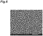
- FIG. 6 is a diagram illustrating an SEM image of the surface (surface on the opening 35 side) of the body layer 31 as an example.
- the body layer 31 illustrated in FIG. 6 is formed by anodizing the surface layer of the Al substrate in two stages.
- the average value of the widths W of the plurality of holes 33 (black portion) is 110 nm
- the average value of the depths D of the plurality of holes 33 is 10 ⁇ m
- the value obtained by dividing the average value of the depths D by the average value of the widths W is 91.
- FIG. 7 is a diagram illustrating an SEM image of a cross section (cross section parallel to the Z-axis direction) of the porous layer 3 as an example.
- the porous layer 3 illustrated in FIG. 7 is formed by performing evaporation of Pt on the surface (surface on the opening 35 side) of the body layer 31.
- the evaporation of Pt from the direction inclined at 30 degrees with respect to the direction perpendicular to the surface of the body layer 31 is performed.
- the thickness T of the conductive layer 32 is 50 nm, and the amount of penetration of the conductive layer 32 (width of the "range in which the conductive layer 32 is formed" in the direction perpendicular to the surface of the body layer 31) is 506 nm.
- the amount of penetration of the conductive layer 32 is sufficiently ensured with respect to the thickness T of the conductive layer 32.
- the sample support body 1 is prepared (preparing process).
- the sample S is arranged in the surface 3a of the porous layer 3 of the sample support body 1 (arrangement process).
- the first region A1 of the surface 3a is pressed against the sample S to transfer the components of the sample S to the first region A1 of the surface 3a.
- the sample support body 1 is mounted in the mass spectrometer, and as illustrated in (b) of FIG. 8 , the surface 3a of the porous layer 3 of the sample support body 1 is irradiated with laser beams (energy rays) L, while applying a voltage to the conductive layer 32 of the sample support body 1 (refer to FIG. 1 ). Accordingly, components S1 of the sample S arranged on the surface 3a is ionized (ionization process). As an example, the components S1 of the sample S arranged on the surface 3a are scanned with the laser beams L.
- the above-described processes correspond to the ionization method using the sample support body 1.
- An example of the ionization method described above is implemented as the surface-assisted laser desorption/ionization (SALDI) method.
- SALDI surface-assisted laser desorption/ionization
- sample ions (ionized components) S2 released by the ionization of the components S1 of the sample S are detected in the mass spectrometer (detection process), and imaging mass spectrometry of imaging the two-dimensional distribution of the molecules constituting the sample S is performed.
- the mass spectrometer is a scanning mass spectrometer using time-of-flight mass spectrometry (TOF-MS).
- TOF-MS time-of-flight mass spectrometry
- the sample support body 1 is provided with the porous layer 3 on the substrate 2.
- the sample support body 1 can be easy to handle.
- the average value of the depths D of the plurality of holes 33 is 3 ⁇ m or more and 100 ⁇ m or less, and the value obtained by dividing the average value of the depths D by the average value of the widths W of the plurality of holes 33 is 9 or more and 2500 or less, excess liquid (moisture or the like) contained in the sample S can easily escape into the plurality of holes 33. Furthermore, since each hole 33 includes the opening 35 widened toward the surface 3a of the porous layer 3, the components S1 of the sample S are likely to remain on the surface 3a side of the porous layer 3, and additionally, the irradiation area of the laser beams L for ionizing the components S1 of the sample S increases.
- the sample support body 1 is easy to handle and suitable for imaging mass spectrometry.
- the average value of the widths W of the plurality of holes 33 is 40 nm or more and 350 nm or less.
- the body layer 31 is an insulating layer
- the porous layer 3 includes the conductive layer 32 formed along at least the surface 3a of the porous layer 3 and the inner surface 35a of each opening 35.
- the thickness of the conductive layer 32 is 10 nm or more and 200 nm or less. Accordingly, the components S1 of the sample S can be ionized with high efficiency by adjusting the resistance value of the conductive layer 32.
- the substrate 2 and the body layer 31 are formed by anodizing the surface layer of the metal substrate.
- the structure in which excess liquid contained in the sample S easily escapes into the plurality of holes 33 and the components S1 of the sample S easily remain on the surface 3a side of the porous layer 3 can reliably and easily be obtained.
- the regularity and uniformity of the arrangement and shape of the plurality of holes 33 are improved by anodizing in two stages. As a result, the efficiency (sensitivity) of ionizing the components S1 of the sample S in the region A can be suppressed from being varied.
- the components S1 of the sample S can be ionized with high efficiency while maintaining the position information of the components S1 of the sample S as described above.
- the mass spectrometry method using the sample support body 1 the two-dimensional distribution of molecules constituting the sample S can be imaged with high sensitivity.
- FIG. 9 illustrate an optical image of the brain portion of the mouse (left side) and an "image illustrating the two-dimensional distribution of m/z 848.6" of the brain portion of the mouse (right side).
- (a) of FIG. 9 is the result of the case using the "sample support body 1 in which the average value of the widths W of the plurality of holes 33 is 110 nm, the average value of the depths D of the plurality of holes 33 is 10 ⁇ m, and the value obtained by dividing the average value of the depths D by the average value of the widths W is 91".
- FIG. 9 illustrate an optical image of the brain portion of the mouse (left side) and an "image illustrating the two-dimensional distribution of m/z 848.6" of the brain portion of the mouse (right side).
- (a) of FIG. 9 is the result of the case using the "sample support body 1 in which the average value of the widths W of the plurality of holes 33 is 110 nm, the average value of the depths D of
- FIG. 9 is the result of the case using the "sample support body 1 in which the average value of the widths W of the plurality of holes 33 is 40 nm, the average value of the depths D of the plurality of holes 33 is 100 ⁇ m, and the value obtained by dividing the average value of the depths D by the average value of the widths W is 2500".
- (c) of FIG. 9 is the result of the case using the "sample support body 1 in which the average value of the widths W of the plurality of holes 33 is 350 nm, the average value of the depths D of the plurality of holes 33 is 3 ⁇ m, and the value obtained by dividing the average value of the depths D by the average value of the widths W is 9".
- the two-dimensional distribution of m/z 848.6 can be fully confirmed.
- FIG. 10 illustrate an optical image of the brain portion of the mouse (left side), an "image illustrating the two-dimensional distribution of m/z 756.6" of the brain portion of the mouse (second from left), an “image illustrating the two-dimensional distribution of m/z 832.6" of the brain portion of the mouse (second from right), and an “image illustrating the two-dimensional distribution of m/z 834.6" of the brain portion of the mouse (right).
- sample support body 1 Example in which the average value of the widths W of the plurality of holes 33 is 100 nm, the average value of the depths D of the plurality of holes 33 is 10 ⁇ m, the value obtained by dividing the average value of the depths D by the average value of the widths W is 100, and each hole 33 does not include the opening 35". (b) of FIG.
- sample support body Comparative Example
- the average value of the widths W of the plurality of holes 33 is 100 nm
- the average value of the depths D of the plurality of holes 33 is 10 ⁇ m
- the value obtained by dividing the average value of the depths D by the average value of the widths W is 100
- each hole 33 does not include the opening 35.
- the two-dimensional distribution of any m/z values the two-dimensional distribution can be confirmed more clearly in the sample support body 1 of Example than in the sample support body of Comparative Example.
- (a) of FIG. 11 is a graph illustrating a relationship between the m/z value and the intensity in the case of (a) of FIG. 10
- (b) of FIG. 11 is a graph illustrating a relationship between the m/z value and the intensity in the case of (b) of FIG. 10 .
- the sensitivity of the sample support body 1 of Example is 1.65 times in average higher than that of the sample support body of Comparative Example.
- the porous layer 3 may not include the conductive layer 32, and the body layer 31 that is an insulating layer may be exposed to the outside at least at the surface 3a of the porous layer 3 and the inner surface 35a of each opening 35.
- the surface 3a that is, the body layer 31, which is the insulating layer
- the position information of the components S1 of the sample S can be maintained, and the components S1 of the sample S can be ionized with high efficiency.
- the ionization method and mass spectrometry method using the sample support body 1 in which the porous layer 3 does not include the conductive layer 32 are as follows. First, the sample support body 1 is prepared (preparing process). Subsequently, the sample S is arranged on the surface 3a of the porous layer 3 (that is, the surface of the body layer 31) of the sample support body 1 (arrangement process). Subsequently, in the mass spectrometer, the surface 3a of the porous layer 3 of the sample support body 1 is irradiated with charged-droplets to ionize the components S1 of the sample S (ionization process). As an example, the components S1 of the sample S arranged on the surface 3a are scanned with the charged-droplets.
- the above-described processes correspond to the ionization method using the sample support body 1.
- An example of the ionization method described above is implemented as a desorption electrospray ionization method (DESI).
- DESI desorption electrospray ionization method
- the sample ions S2 emitted by the ionization of the components S1 of the sample S are detected by the mass spectrometer (detection process), and imaging mass spectrometry is performed to image the two-dimensional distribution of the molecules constituting the sample S.
- the above-described processes correspond to the mass spectrometry method using the sample support body 1.
- the average value of the widths W may not be 40 nm or more and 350 nm or less.
- the thickness T of the conductive layer 32 may not be 10 nm or more and 200 nm or less.
- the conductive layer 32 may reach the inner surface of the extension portion 34 at each hole 33.
- the body layer 31 may be a conductive layer (for example, a metal layer or the like). In that case, the conductive layer 32 can be omitted from the porous layer 3.
- the substrate 2 and the body layer 31 may be formed by anodizing the surface layer of the silicon (Si) substrate.
- the surface 3a of the porous layer 3 of the sample support body 1 may be irradiated with energy rays (for example, ion beams, electron beams, or the like) other than the laser beams L.
- energy rays for example, ion beams, electron beams, or the like
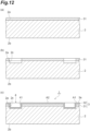
- the partition portion 4 may be formed as follows. First, as illustrated in (a) of FIG. 12 , the substrate 2 is prepared, and the body layer 31 is formed on the surface 2a of the substrate 2. Subsequently, as illustrated in (b) of FIG. 12 , the groove 2c reaching the substrate 2 is formed on the body layer 31. Subsequently, as illustrated in (c) of FIG. 12 , the conductive layer 32 is formed on the body layer 31. At this time, the conductive layer 32 is also formed on the inner surface of the groove 2c. According to the description above, the sample support body 1 is obtained. It is noted that the display portion 5 may also be formed in the same manner as the partition portion 4 is formed.
Landscapes
- Chemical & Material Sciences (AREA)
- Analytical Chemistry (AREA)
- Other Investigation Or Analysis Of Materials By Electrical Means (AREA)
Abstract
Description
- The present disclosure relates to a sample support body, an ionization method, and a mass spectrometry method.
-
Patent Literature 1 discloses a sample support body including a substrate provided with a plurality of through holes. The sample support body disclosed inPatent Literature 1 is used, as one application, in imaging mass spectrometry for imaging a two-dimensional distribution of molecules constituting a sample. However, in the sample support body disclosed inPatent Literature 1, a thickness of the substrate may be about several µm, and in such some cases, when pressing the substrate against the sample and transferring components of the sample to the substrate, care is required to be taken in handling so as not to break the substrate. -
Patent Literature 2 discloses a sample target including a layer of aluminum and a layer of porous alumina provided on the layer of aluminum. In the sample target disclosed inPatent Literature 2, for example, when the layer of aluminum is thickened, it is considered that the layer of porous alumina is less likely to break. -
- Patent Literature 1:
Japanese Patent No. 6093492 - Patent Literature 2:
Japanese Patent No. 4885142 - However, the sample target disclosed in
Patent Literature 2 is intended for application to mass spectrometry, and cannot be said to be intended for application to imaging mass spectrometry. - Accordingly, an object of the present disclosure is to provide a sample support body that is easy to handle and suitable for imaging mass spectrometry and an ionization method and a mass spectrometry method using such a sample support body.
- A sample support body according to one aspect of the present disclosure is a sample support body used for ionizing components of a sample, including: a substrate; and a porous layer provided on the substrate and having a surface opposite to the substrate, in which the porous layer includes a body layer having a plurality of holes open to the surface, in which each of the plurality of holes includes: an extension portion extending in a thickness direction of the substrate; and an opening widened from an end of the extension portion on a surface side toward the surface, in which an average value of depths of the plurality of holes is 3 µm or more and 100 µm or less, and in which a value obtained by dividing the average value of the depths by an average value of widths of the plurality of holes is 9 or more and 2500 or less.
- In the sample support body, the porous layer is provided on the substrate. Accordingly, for example, even when the surface of the porous layer is pressed against the sample in order to transfer the components of the sample to the surface of the porous layer, since the porous layer is unlikely to be broken, the sample support body can be easy to handle. In addition, since the average value of the depths of the plurality of holes is 3 µm or more and 100 µm or less and the value obtained by dividing the average value of the depths by the average value of the widths of the plurality of holes is 9 or more and 2500 or less, excess liquid (moisture or the like) contained in the sample can easily escape into the plurality of holes. Furthermore, since each of the plurality of holes includes the opening widened toward the surface of the porous layer, the components of the sample are likely to remain on the surface side of the porous layer, and the irradiation area of the energy rays for ionizing the components of the sample increases. Accordingly, for example, by irradiating the surface of the porous layer with the energy rays, the components of the sample can be ionized with high efficiency while maintaining the position information (two-dimensional distribution information of the molecules constituting the sample) of the sample components. As described above, the sample support body is easy to handle and suitable for imaging mass spectrometry.
- In the sample support body according to one aspect of the present disclosure, the average value of the widths may be 40 nm or more and 350 nm or less. Accordingly, the structure in which excess liquid contained in the sample easily escapes into the plurality of holes and the components of the sample easily remain on the surface side of the porous layer can reliably and easily be obtained.
- In the sample support body according to one aspect of the present disclosure, the body layer may be an insulating layer, and the porous layer may further include a conductive layer formed along at least the surface and an inner surface of the opening. Accordingly, by irradiating the surface (that is, the conductive layer) of the porous layer with the energy rays, the components of the sample can be ionized with high efficiency while maintaining the position information of the components of the sample.
- In the sample support body according to one aspect of the present disclosure, the conductive layer may have a thickness of 10 nm or more and 200 nm or less. Accordingly, the components of the sample can be ionized with high efficiency by adjusting a resistance value of the conductive layer.
- In the sample support body according to one aspect of the present disclosure, the body layer may be an insulating layer, and the body layer may be exposed to an outside at least on the surface and an inner surface of the opening. Accordingly, by irradiating the surface of the porous layer (that is, the body layer that is an insulating layer) with charged-droplets, the components of the sample can be ionized with high efficiency while maintaining the position information of the components of the sample.
- In the sample support body according to one aspect of the present disclosure, the substrate and the body layer may be formed by anodizing a surface layer of a metal substrate or a silicon substrate. Accordingly, the structure in which excess liquid contained in the sample easily escapes into the plurality of holes and the components of the sample easily remain on the surface side of the porous layer can reliably and easily be obtained.
- An ionization method according to one aspect of the present disclosure includes processes of: a process of preparing the sample support body in which the porous layer includes the conductive layer; a process of arranging the sample on the surface; and a process of ionizing the components by irradiating the surface with energy rays.
- According to the ionization method, as described above, the components of the sample can be ionized with high efficiency while maintaining the position information of the components of the sample.
- An ionization method according to one aspect of the present disclosure includes processes of: a process of preparing the sample support body in which the body layer which is the insulating layer is exposed to an outside in the porous layer; a process of arranging the sample on the surface; and a process of ionizing the components by irradiating the surface with charged-droplets.
- According to the ionization method, as described above, it is possible to ionize the components of the sample with high efficiency while maintaining the position information of the components of the sample.
- A mass spectrometry method according to one aspect of the present disclosure includes a plurality of processes included in the ionization method and a process of detecting the ionized components.
- According to the mass spectrometry method, the two-dimensional distribution of molecules constituting the sample can be imaged with high sensitivity.
- According to the present disclosure, it is possible to provide a sample support body that is easy to handle and suitable for imaging mass spectrometry and an ionization method and a mass spectrometry method using the sample support body.
-
-
FIG. 1 is a plan view of a sample support body of one embodiment. -
FIG. 2 is a cross-sectional view of the sample support body taken along line II-II illustrated inFIG. 1 . -
FIG. 3 is a cross-sectional view of a porous layer illustrated inFIG. 2 . -
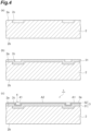
FIG. 4 are diagrams illustrating a process of manufacturing the sample support body illustrated inFIG. 2 . -
FIG. 5 are diagrams illustrating a process of forming a body layer illustrated inFIG. 3 . -
FIG. 6 is a diagram illustrating an SEM image of a surface of the body layer as an example. -
FIG. 7 is a diagram illustrating the SEM image of a cross section of the porous layer as an example. -
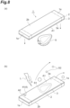
FIG. 8 are diagrams illustrating an ionization method and a mass spectrometry method using the sample support body illustrated inFIG. 1 . -
FIG. 9 are optical images of a brain portion of a mouse, and "images illustrating a two-dimensional distribution of m/z 848.6" of the brain portion of the mouse. -
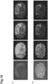
FIG. 10 illustrates an optical image of the brain portion of the mouse, an "image illustrating a two-dimensional distribution of m/z 756.6" of the brain portion of the mouse, an "image illustrating the two-dimensional distribution of m/z 832.6" of the brain portion of the mouse, and an "image illustrating the two-dimensional distribution of m/z 834.6" of the brain portion of the mouse. -
FIG. 11 are graphs illustrating a relationship between an m/z value and an intensity. -
FIG. 12 are diagrams illustrating a process of manufacturing a sample support body according to Modified Example. - Hereinafter, embodiments of the present disclosure will be described in detail with reference to the drawings. It is noted that, in each figure, the same or corresponding components are denoted by the same reference numerals, and redundant descriptions are omitted.
- As illustrated in
FIGS. 1 and2 , asample support body 1 has asubstrate 2 and aporous layer 3. Thesample support body 1 is used for ionizing components of the sample. Hereinafter, a thickness direction of thesubstrate 2 is referred to as a Z-axis direction, one direction perpendicular to the Z-axis direction is referred to as an X-axis direction, and a direction perpendicular to both the Z-axis direction and the X-axis direction is referred to as a Y-axis direction. - The
substrate 2 has afront surface 2a and aback surface 2b perpendicular to the Z-axis direction. A shape of thesubstrate 2 is, for example, a rectangular plate shape of which longitudinal direction is the X-axis direction. A thickness of thesubstrate 2 is, for example, approximately 0.5 to 1 mm. A material of thesubstrate 2 is, for example, aluminum (Al). - The
porous layer 3 is provided on thesubstrate 2. Specifically, theporous layer 3 is formed over theentire surface 2a of thesubstrate 2. Theporous layer 3 has asurface 3a on the opposite side of thesubstrate 2. Theporous layer 3 includes abody layer 31 that is an insulating layer. A material of thebody layer 31 is, for example, alumina (Al2O3). - As illustrated in
FIG. 3 , thebody layer 31 has a plurality ofholes 33 opening to thesurface 3a. Eachhole 33 includes anextension portion 34 and anopening 35. Theextension portion 34 extends in the Z-axis direction. A shape of theextension portion 34 when viewed from the Z-axis direction is, for example, a circular shape. Theopening 35 is widened from anend 34a of theextension portion 34 on the side of thesurface 3a toward thesurface 3a. A shape of theopening 35 is, for example, a bowl shape or a truncated cone shape (tapered shape) expanding from theend 34a of theextension portion 34 toward thesurface 3a. It is noted that the end of theextension portion 34 on the side of thesubstrate 2 is positioned inside thebody layer 31. - The
porous layer 3 further includes aconductive layer 32. Theconductive layer 32 is formed along at least thesurface 3a and aninner surface 35a of each opening 35 of theporous layer 3. In thesample support body 1, a material of theconductive layer 32 is a metal having low affinity (reactivity) with the sample and high conductivity. Examples of such metals include Au (gold), Pt (platinum), Cr (chromium), Ni (nickel), and Ti (titanium). - As illustrated in
FIG. 1 , both ends 1a of thesample support body 1 in the X-axis direction (both ends outside a chain double-dashed line inFIG. 1 ) function as held portions, for example, when thesample support body 1 is mounted in a mass spectrometer. A region A between both ends 1a of thesurface 3a of theporous layer 3 functions as a measurement region. The region A has, for example, a rectangular shape of which longitudinal direction is the X-axis direction. - The
sample support body 1 further includes apartition portion 4 and a plurality ofdisplay portions 5. Thepartition portion 4 is arranged, for example, at one corner of the region A. Eachdisplay portion 5 is arranged, for example, at each of the three corners of the region A (three corners where thepartition portion 4 is not arranged). - The
partition portion 4 includes apartition groove 41 extending in an annular shape. Thepartition groove 41 is formed on thesurface 3a of theporous layer 3 so as to pass between a first region A1 and a second region A2. The first region A1 is a region of the region A outside thepartition groove 41. The second region A2 is a region of the region A inside thepartition groove 41. Thepartition portion 4 partitions the region A into the first region A1 and the second region A2. - As illustrated in
FIG. 2 , thepartition groove 41 is formed on thesurface 3a of theporous layer 3 by falling theporous layer 3 into agroove 2c formed on thesurface 2a of thesubstrate 2. The width of thepartition groove 41 is larger than the depth of the partition groove 42. As an example, the depth of thepartition groove 41 is 50 µm or more and 300 µm or less, and the width of thepartition groove 41 is twice or more the depth of thepartition groove 41. - As illustrated in
FIG. 1 , eachdisplay portion 5 includes adisplay groove 51 extending in an X shape. Thedisplay groove 51 is formed on thesurface 3a of theporous layer 3 so as to display predetermined information. Similarly to thepartition groove 41, thedisplay groove 51 is formed on thesurface 3a of theporous layer 3 by falling theporous layer 3 into the grooves formed on thesurface 2a of thesubstrate 2. For thesample support body 1, the predetermined information is information about the position and angle of thesample support body 1 when thesample support body 1 is mounted in the mass spectrometer, and for example, the predetermined information is used for alignment of thesample support body 1 when thesample support body 1 is mounted in the mass spectrometer. - The dimensions of the
porous layer 3 will be described. As illustrated inFIG. 3 , the average value of depths D of the plurality ofholes 33 is 3 µm or more and 100 µm or less. As an example, in the region A, the number ofholes 33 having the depth D of which the average value is ±10% is 60% or more (preferably 70% or more, more preferably 80% or more) of the total number ofholes 33. The average value of widths W of the plurality ofholes 33 is 40 nm or more and 350 nm or less. As an example, in the region A, the number ofholes 33 having the width W of which the average value is ±10% is 60% or more (preferably 70% or more, more preferably 80% or more) of the total number ofholes 33. The value obtained by dividing the average value of the depths D by the average value of the widths W is 9 or more and 2500 or less. As an example, in the region A, the number ofholes 33 having "the obtained by dividing the average value of the depths D by the average value of the widths W" of the average value of ±10% is 60% or more (preferably 70% or more, more preferably 80% or more) of the total number of theholes 33. The thickness T of theconductive layer 32 is 10 nm or more and 200 nm or less. - The average value of depths D is a value obtained as follows. First, the
sample support body 1 is prepared and cut parallel to the Z-axis direction. Subsequently, an SEM image of one of the cut surfaces of thebody layer 31 is obtained. Subsequently, in the region corresponding to the region A, the average value of the depths D of the plurality ofholes 33 is calculated to obtain the average value of the depths D. - The average value of widths W is the value obtained as follows. First, the
sample support body 1 is prepared, and the sample support body 1 (specifically, the body layer 31) is cut perpendicularly to the Z-axis direction so as to traverse the plurality ofextension portions 34. Subsequently, an SEM image of one of the cut surfaces of thebody layer 31 is obtained. Subsequently, in the region corresponding to the region A, the plurality of pixel groups corresponding to the plurality of holes 33 (specifically, the plurality of extension portions 34) are extracted. The extraction of the pixel groups is performed, for example, by performing a binarization process on an SEM image. Subsequently, by calculating the diameter of a circle having an average value of the areas of the plurality of holes 33 (specifically, the plurality of extension portions 34), the diameter is obtained as the average value of the widths W based on the plurality of pixel groups. - The
substrate 2 and thebody layer 31 are formed by anodizing the surface layer of the metal substrate. Thesubstrate 2 and thebody layer 31 are formed, for example, by anodizing the surface layer of the Al substrate. It is noted that, in addition to an Al substrate, as a metal substrate, a tantalum (Ta) substrate, a niobium (Nb) substrate, a titanium (Ti) substrate, a hafnium (Hf) substrate, a zirconium (Zr) substrate, a zinc (Zn) substrate, a tungsten (W) substrate, a bismuth (Bi) substrate, an antimony (Sb) substrate, and the like are exemplified. - The plurality of
holes 33 each having a substantially constant width W are formed uniformly (distributed uniformly) in thebody layer 31. The pitch (distance between center lines) of theadjacent holes 33 is, for example, about 275 nm. It is preferable that an aperture ratio (a ratio of the plurality ofholes 33 to the region A when viewed from the Z-axis direction) of the plurality ofholes 33 in the region A is practically 10 to 80%, particularly 60 to 80%. It is noted that, in the plurality ofholes 33, the width W of eachhole 33 may be uneven, or theholes 33 may be partially connected to each other. - The method for manufacturing the
sample support body 1 will be described. First, as illustrated in (a) ofFIG. 4 , thesubstrate 2 is prepared, and thegroove 2c for thepartition portion 4 is formed on thesurface 2a of thesubstrate 2. At this time, the grooves for the plurality ofdisplay portions 5 illustrated inFIG. 1 are also formed on thesurface 2a of thesubstrate 2. For example, etching, laser processing, machining, or the like is used for forming thegrooves 2c for thepartition portion 4 and the grooves for the plurality ofdisplay portions 5. - Subsequently, as illustrated in (b) of
FIG. 4 , thebody layer 31 is formed in thesurface 2a of thesubstrate 2. Subsequently, as illustrated in (c) ofFIG. 4 , theconductive layer 32 is formed on thebody layer 31. For example, an evaporation method, a sputtering method, a plating method, an atomic layer deposition (ALD) method, or the like is used for forming theconductive layer 32. - As described above, the
sample support body 1 is obtained. In the method for manufacturing thesample support body 1 described above, thepartition grooves 41 are formed on thesurface 3a of theporous layer 3 by falling theporous layer 3 into thegrooves 2c for thepartition portion 4. Further, the plurality ofdisplay grooves 51 illustrated inFIG. 1 are formed on thesurface 3a of theporous layer 3 by falling theporous layer 3 into the grooves for the plurality ofdisplay portions 5. - Formation of the
body layer 31 will be described. First, as illustrated in (a) ofFIG. 5 , thesubstrate 2 is prepared, and theoxide layer 30 is formed on thesurface 2a of thesubstrate 2 by anodizing the surface layer of thesubstrate 2. Theoxide layer 30 has a plurality ofholes 30a that open on the side opposite to thesubstrate 2. - Subsequently, as illustrated in (b) of
FIG. 5 , thesurface 2a of thesubstrate 2 is exposed to the outside by removing theoxide layer 30. A plurality of bowl-shaped or truncated-cone-shaped (tapered) recesses are formed on thesurface 2a of thesubstrate 2. The plurality of recesses are formed at positions corresponding to the plurality ofholes 30a. - Subsequently, as illustrated in (c) of
FIG. 5 , thebody layer 31 is formed on thesurface 2a of thesubstrate 2 by anodizing the surface layer of thesubstrate 2 again. In thebody layer 31, eachhole 33 includes theopening 35 widened from theend 34a of theextension portion 34 toward the side opposite to thesubstrate 2. Theopening 35 is formed in eachhole 33 by performing anodization in two stages as described above. In addition, since the anodization is performed in two stages, the regularity and uniformity of the arrangement and shape of the plurality ofholes 33 are improved. It is noted that, in the formation of thebody layer 31 described above, thesubstrate 2 is an Al substrate, and theoxide layer 30 and thebody layer 31 are Al2O3 layers. -
FIG. 6 is a diagram illustrating an SEM image of the surface (surface on theopening 35 side) of thebody layer 31 as an example. Thebody layer 31 illustrated inFIG. 6 is formed by anodizing the surface layer of the Al substrate in two stages. In thebody layer 31 illustrated inFIG. 6 , the average value of the widths W of the plurality of holes 33 (black portion) is 110 nm, the average value of the depths D of the plurality ofholes 33 is 10 µm, and the value obtained by dividing the average value of the depths D by the average value of the widths W is 91. -
FIG. 7 is a diagram illustrating an SEM image of a cross section (cross section parallel to the Z-axis direction) of theporous layer 3 as an example. Theporous layer 3 illustrated inFIG. 7 is formed by performing evaporation of Pt on the surface (surface on theopening 35 side) of thebody layer 31. Here, while rotating thebody layer 31, the evaporation of Pt from the direction inclined at 30 degrees with respect to the direction perpendicular to the surface of thebody layer 31 is performed. In theporous layer 3 illustrated inFIG. 7 , the thickness T of theconductive layer 32 is 50 nm, and the amount of penetration of the conductive layer 32 (width of the "range in which theconductive layer 32 is formed" in the direction perpendicular to the surface of the body layer 31) is 506 nm. In theporous layer 3 illustrated inFIG. 7 , since eachhole 33 includes theopening 35, it is considered that the amount of penetration of theconductive layer 32 is sufficiently ensured with respect to the thickness T of theconductive layer 32. - The ionization method and the mass spectrometry method using the
sample support body 1 will be described. First, as illustrated in (a) ofFIG. 8 , thesample support body 1 is prepared (preparing process). Subsequently, the sample S is arranged in thesurface 3a of theporous layer 3 of the sample support body 1 (arrangement process). As an example, the first region A1 of thesurface 3a is pressed against the sample S to transfer the components of the sample S to the first region A1 of thesurface 3a. - Subsequently, the
sample support body 1 is mounted in the mass spectrometer, and as illustrated in (b) ofFIG. 8 , thesurface 3a of theporous layer 3 of thesample support body 1 is irradiated with laser beams (energy rays) L, while applying a voltage to theconductive layer 32 of the sample support body 1 (refer toFIG. 1 ). Accordingly, components S1 of the sample S arranged on thesurface 3a is ionized (ionization process). As an example, the components S1 of the sample S arranged on thesurface 3a are scanned with the laser beams L. The above-described processes correspond to the ionization method using thesample support body 1. An example of the ionization method described above is implemented as the surface-assisted laser desorption/ionization (SALDI) method. - Subsequently, sample ions (ionized components) S2 released by the ionization of the components S1 of the sample S are detected in the mass spectrometer (detection process), and imaging mass spectrometry of imaging the two-dimensional distribution of the molecules constituting the sample S is performed. As an example, the mass spectrometer is a scanning mass spectrometer using time-of-flight mass spectrometry (TOF-MS). The above-described processes correspond to the mass spectrometry method using the
sample support body 1. It is noted that the second region A2 is used, for example, as a region onto which the reagent for mass calibration is dropped. - As described above, the
sample support body 1 is provided with theporous layer 3 on thesubstrate 2. As a result, for example, even when thesurface 3a of theporous layer 3 is pressed against the sample S in order to transfer the components S1 of the sample S to thesurface 3a of theporous layer 3, since theporous layer 3 is unlikely to be broken, thesample support body 1 can be easy to handle. Further, the average value of the depths D of the plurality ofholes 33 is 3 µm or more and 100 µm or less, and the value obtained by dividing the average value of the depths D by the average value of the widths W of the plurality ofholes 33 is 9 or more and 2500 or less, excess liquid (moisture or the like) contained in the sample S can easily escape into the plurality ofholes 33. Furthermore, since eachhole 33 includes theopening 35 widened toward thesurface 3a of theporous layer 3, the components S1 of the sample S are likely to remain on thesurface 3a side of theporous layer 3, and additionally, the irradiation area of the laser beams L for ionizing the components S1 of the sample S increases. Accordingly, for example, by irradiating thesurface 3a of theporous layer 3 with the laser beams L, the position information (the two-dimensional distribution information of the molecules constituting the sample S) of the components S1 of the sample S can be maintained and the components S1 of the sample S can be ionized with high efficiency. As described above, thesample support body 1 is easy to handle and suitable for imaging mass spectrometry. - In the
sample support body 1, the average value of the widths W of the plurality ofholes 33 is 40 nm or more and 350 nm or less. As a result, the structure in which excess liquid contained in the sample S easily escapes into the plurality ofholes 33 and the components S1 of the sample S easily remain on thesurface 3a side of theporous layer 3 can reliably and easily be obtained. - In the
sample support body 1, thebody layer 31 is an insulating layer, and theporous layer 3 includes theconductive layer 32 formed along at least thesurface 3a of theporous layer 3 and theinner surface 35a of eachopening 35. Thus, by irradiating thesurface 3a (that is, the conductive layer 32) of theporous layer 3 with the laser beams L, the components S1 of the sample S can be ionized with high efficiency while maintaining the position information of the components S1 of the sample S. - In the
sample support body 1, the thickness of theconductive layer 32 is 10 nm or more and 200 nm or less. Accordingly, the components S1 of the sample S can be ionized with high efficiency by adjusting the resistance value of theconductive layer 32. - In the
sample support body 1, thesubstrate 2 and thebody layer 31 are formed by anodizing the surface layer of the metal substrate. As a result, the structure in which excess liquid contained in the sample S easily escapes into the plurality ofholes 33 and the components S1 of the sample S easily remain on thesurface 3a side of theporous layer 3 can reliably and easily be obtained. In particular, in thesample support body 1, the regularity and uniformity of the arrangement and shape of the plurality ofholes 33 are improved by anodizing in two stages. As a result, the efficiency (sensitivity) of ionizing the components S1 of the sample S in the region A can be suppressed from being varied. - According to the ionization method using the
sample support body 1, the components S1 of the sample S can be ionized with high efficiency while maintaining the position information of the components S1 of the sample S as described above. According to the mass spectrometry method using thesample support body 1, the two-dimensional distribution of molecules constituting the sample S can be imaged with high sensitivity. - (a), (b) and (c) of
FIG. 9 illustrate an optical image of the brain portion of the mouse (left side) and an "image illustrating the two-dimensional distribution of m/z 848.6" of the brain portion of the mouse (right side). (a) ofFIG. 9 is the result of the case using the "sample support body 1 in which the average value of the widths W of the plurality ofholes 33 is 110 nm, the average value of the depths D of the plurality ofholes 33 is 10 µm, and the value obtained by dividing the average value of the depths D by the average value of the widths W is 91". (b) ofFIG. 9 is the result of the case using the "sample support body 1 in which the average value of the widths W of the plurality ofholes 33 is 40 nm, the average value of the depths D of the plurality ofholes 33 is 100 µm, and the value obtained by dividing the average value of the depths D by the average value of the widths W is 2500". (c) ofFIG. 9 is the result of the case using the "sample support body 1 in which the average value of the widths W of the plurality ofholes 33 is 350 nm, the average value of the depths D of the plurality ofholes 33 is 3 µm, and the value obtained by dividing the average value of the depths D by the average value of the widths W is 9". In any cases, the two-dimensional distribution of m/z 848.6 can be fully confirmed. - (a) and (b) of
FIG. 10 illustrate an optical image of the brain portion of the mouse (left side), an "image illustrating the two-dimensional distribution of m/z 756.6" of the brain portion of the mouse (second from left), an "image illustrating the two-dimensional distribution of m/z 832.6" of the brain portion of the mouse (second from right), and an "image illustrating the two-dimensional distribution of m/z 834.6" of the brain portion of the mouse (right). (a) ofFIG. 10 is the result of the case using the "sample support body 1 (Example) in which the average value of the widths W of the plurality ofholes 33 is 100 nm, the average value of the depths D of the plurality ofholes 33 is 10 µm, the value obtained by dividing the average value of the depths D by the average value of the widths W is 100, and eachhole 33 does not include theopening 35". (b) ofFIG. 10 is the result of the case using the "sample support body (Comparative Example) in which the average value of the widths W of the plurality ofholes 33 is 100 nm, the average value of the depths D of the plurality ofholes 33 is 10 µm, the value obtained by dividing the average value of the depths D by the average value of the widths W is 100, and eachhole 33 does not include theopening 35". With respect to the two-dimensional distribution of any m/z values, the two-dimensional distribution can be confirmed more clearly in thesample support body 1 of Example than in the sample support body of Comparative Example. - (a) of
FIG. 11 is a graph illustrating a relationship between the m/z value and the intensity in the case of (a) ofFIG. 10 , and(b) ofFIG. 11 is a graph illustrating a relationship between the m/z value and the intensity in the case of (b) ofFIG. 10 . As a result, the sensitivity of thesample support body 1 of Example is 1.65 times in average higher than that of the sample support body of Comparative Example. - The present disclosure is not limited to the embodiments described above. For example, the
porous layer 3 may not include theconductive layer 32, and thebody layer 31 that is an insulating layer may be exposed to the outside at least at thesurface 3a of theporous layer 3 and theinner surface 35a of eachopening 35. In that case, by irradiating thesurface 3a (that is, thebody layer 31, which is the insulating layer) of theporous layer 3 with charged-droplets, the position information of the components S1 of the sample S can be maintained, and the components S1 of the sample S can be ionized with high efficiency. - The ionization method and mass spectrometry method using the
sample support body 1 in which theporous layer 3 does not include theconductive layer 32 are as follows. First, thesample support body 1 is prepared (preparing process). Subsequently, the sample S is arranged on thesurface 3a of the porous layer 3 (that is, the surface of the body layer 31) of the sample support body 1 (arrangement process). Subsequently, in the mass spectrometer, thesurface 3a of theporous layer 3 of thesample support body 1 is irradiated with charged-droplets to ionize the components S1 of the sample S (ionization process). As an example, the components S1 of the sample S arranged on thesurface 3a are scanned with the charged-droplets. The above-described processes correspond to the ionization method using thesample support body 1. An example of the ionization method described above is implemented as a desorption electrospray ionization method (DESI). Subsequently, the sample ions S2 emitted by the ionization of the components S1 of the sample S are detected by the mass spectrometer (detection process), and imaging mass spectrometry is performed to image the two-dimensional distribution of the molecules constituting the sample S. The above-described processes correspond to the mass spectrometry method using thesample support body 1. - In any
sample support body 1, when the average value of the depths D of the plurality ofholes 33 is 3 µm or more and 100 µm or less and the value obtained by dividing the average value of the depths D by the average value of the widths W of the plurality ofholes 33 is 9 or more and 2500 or less, the average value of the widths W may not be 40 nm or more and 350 nm or less. In that case, when theporous layer 3 includes theconductive layer 32, the thickness T of theconductive layer 32 may not be 10 nm or more and 200 nm or less. - In the
sample support body 1 in which theporous layer 3 includes theconductive layer 32, theconductive layer 32 may reach the inner surface of theextension portion 34 at eachhole 33. - The
body layer 31 may be a conductive layer (for example, a metal layer or the like). In that case, theconductive layer 32 can be omitted from theporous layer 3. - The
substrate 2 and thebody layer 31 may be formed by anodizing the surface layer of the silicon (Si) substrate. - In the ionization using the
sample support body 1 in which theporous layer 3 includes theconductive layer 32, thesurface 3a of theporous layer 3 of thesample support body 1 may be irradiated with energy rays (for example, ion beams, electron beams, or the like) other than the laser beams L. - The
partition portion 4 may be formed as follows. First, as illustrated in (a) ofFIG. 12 , thesubstrate 2 is prepared, and thebody layer 31 is formed on thesurface 2a of thesubstrate 2. Subsequently, as illustrated in (b) ofFIG. 12 , thegroove 2c reaching thesubstrate 2 is formed on thebody layer 31. Subsequently, as illustrated in (c) ofFIG. 12 , theconductive layer 32 is formed on thebody layer 31. At this time, theconductive layer 32 is also formed on the inner surface of thegroove 2c. According to the description above, thesample support body 1 is obtained. It is noted that thedisplay portion 5 may also be formed in the same manner as thepartition portion 4 is formed. - 1: sample support body, 2: substrate, 3: porous layer, 3a: surface, 31: body layer, 32: conductive layer, 33: hole, 34: extension portion, 34a: end, 35: opening, 35a: inner surface, L: laser beams (energy ray), S: sample, S1: components, S2: sample ion (ionized components).
Claims (9)
- A sample support body for ionization of components of a sample, comprising:a substrate; anda porous layer provided on the substrate and having a surface opposite to the substrate,wherein the porous layer includes a body layer having a plurality of holes open to the surface,wherein each of the plurality of holes includes:an extension portion extending in a thickness direction of the substrate; andan opening widened from an end of the extension portion on a surface side toward the surface,wherein an average value of depths of the plurality of holes is 3 µm or more and 100 µm or less, andwherein a value obtained by dividing the average value of the depths by an average value of widths of the plurality of holes is 9 or more and 2500 or less.
- The sample support body according to claim 1, wherein the average value of the widths is 40 nm or more and 350 nm or less.
- The sample support body according to claim 1 or 2,wherein the body layer is an insulating layer, andwherein the porous layer further includes a conductive layer formed along at least the surface and an inner surface of the opening.
- The sample support body according to claim 3, wherein the conductive layer has a thickness of 10 nm or more and 200 nm or less.
- The sample support body according to claim 1 or 2,wherein the body layer is an insulating layer, andwherein the body layer is exposed to an outside at least on the surface and an inner surface of the opening.
- The sample support body according to any one of claims 3 to 5, wherein the substrate and the body layer are formed by anodizing a surface layer of a metal substrate or a silicon substrate.
- An ionization method, comprising:a process of preparing the sample support body according to claim 3;a process of arranging the sample on the surface; anda process of ionizing the components by irradiating the surface with energy rays.
- An ionization method, comprising:a process of preparing the sample support body according to claim 5;a process of arranging the sample on the surface; anda process of ionizing the components by irradiating the surface with charged-droplets.
- A mass spectrometry method comprising:a plurality of processes included in the ionization method according to claim 7 or 8; anda process of detecting the ionized components.
Applications Claiming Priority (2)
| Application Number | Priority Date | Filing Date | Title |
|---|---|---|---|
| JP2020206539A JP7449848B2 (en) | 2020-12-14 | 2020-12-14 | Sample support, ionization method and mass spectrometry method |
| PCT/JP2021/038075 WO2022130764A1 (en) | 2020-12-14 | 2021-10-14 | Sample support, ionization method, and mass spectrometry method |
Publications (2)
| Publication Number | Publication Date |
|---|---|
| EP4215909A1 true EP4215909A1 (en) | 2023-07-26 |
| EP4215909A4 EP4215909A4 (en) | 2025-01-08 |
Family
ID=82058993
Family Applications (1)
| Application Number | Title | Priority Date | Filing Date |
|---|---|---|---|
| EP21906128.0A Pending EP4215909A4 (en) | 2020-12-14 | 2021-10-14 | Sample support, ionization method, and mass spectrometry method |
Country Status (5)
| Country | Link |
|---|---|
| US (1) | US20230411133A1 (en) |
| EP (1) | EP4215909A4 (en) |
| JP (1) | JP7449848B2 (en) |
| CN (1) | CN116635715A (en) |
| WO (1) | WO2022130764A1 (en) |
Families Citing this family (2)
| Publication number | Priority date | Publication date | Assignee | Title |
|---|---|---|---|---|
| JP7496300B2 (en) * | 2020-12-14 | 2024-06-06 | 浜松ホトニクス株式会社 | Sample support, ionization method and mass spectrometry method |
| JP7469540B1 (en) * | 2023-06-07 | 2024-04-16 | 浜松ホトニクス株式会社 | Sample support and method for producing the same |
Family Cites Families (11)
| Publication number | Priority date | Publication date | Assignee | Title |
|---|---|---|---|---|
| WO2007046162A1 (en) * | 2005-10-20 | 2007-04-26 | Japan Science And Technology Agency | Sample target for use in mass analysis method, process for producing the same, and mass analysis apparatus using the sample target |
| JP5438330B2 (en) * | 2009-01-28 | 2014-03-12 | 公益財団法人神奈川科学技術アカデミー | Sample target used for mass spectrometry, method for producing the same, and mass spectrometer using the sample target |
| GB2552602B (en) * | 2015-03-06 | 2020-12-30 | Micromass Ltd | Desorption electrospray ionisation mass spectrometry ("DESI-MS") analysis of swabs |
| WO2017038710A1 (en) * | 2015-09-03 | 2017-03-09 | 浜松ホトニクス株式会社 | Sample supporting body and method of manufacturing sample supporting body |
| WO2018126230A1 (en) * | 2016-12-30 | 2018-07-05 | Inredox Llc | Substrate with matrix-free nanostructured hydrophilic analyte spots for use in mass spectrometry |
| CN107941893B (en) * | 2017-10-31 | 2020-06-26 | 中国地质大学(武汉) | Elastic laser ablation sample target holder |
| JP7181901B2 (en) * | 2018-02-09 | 2022-12-01 | 浜松ホトニクス株式会社 | Sample support, ionization method and mass spectrometry method |
| US11404256B2 (en) * | 2018-02-09 | 2022-08-02 | Hamamatsu Photonics K.K. | Sample support, ionization method, and mass spectrometry method |
| JP2020020588A (en) * | 2018-07-30 | 2020-02-06 | 浜松ホトニクス株式会社 | Sample support, sample ionization method, and mass spectrometry |
| JP7227823B2 (en) * | 2019-03-29 | 2023-02-22 | 浜松ホトニクス株式会社 | sample support |
| JP7496300B2 (en) * | 2020-12-14 | 2024-06-06 | 浜松ホトニクス株式会社 | Sample support, ionization method and mass spectrometry method |
-
2020
- 2020-12-14 JP JP2020206539A patent/JP7449848B2/en active Active
-
2021
- 2021-10-14 US US18/037,346 patent/US20230411133A1/en active Pending
- 2021-10-14 CN CN202180083877.XA patent/CN116635715A/en active Pending
- 2021-10-14 WO PCT/JP2021/038075 patent/WO2022130764A1/en not_active Ceased
- 2021-10-14 EP EP21906128.0A patent/EP4215909A4/en active Pending
Also Published As
| Publication number | Publication date |
|---|---|
| CN116635715A (en) | 2023-08-22 |
| EP4215909A4 (en) | 2025-01-08 |
| JP2022093834A (en) | 2022-06-24 |
| JP7449848B2 (en) | 2024-03-14 |
| WO2022130764A1 (en) | 2022-06-23 |
| US20230411133A1 (en) | 2023-12-21 |
Similar Documents
| Publication | Publication Date | Title |
|---|---|---|
| US11935733B2 (en) | Sample support, sample ionization method, and mass spectrometry method | |
| US11189474B2 (en) | Sample support, ionization method, and mass spectrometry method | |
| EP2851931B1 (en) | Microchannel plate | |
| EP3686590B1 (en) | Laser desorption/ionization method and mass spectrometry method | |
| US20230411133A1 (en) | Sample support, ionization method, and mass spectrometry method | |
| EP3751271B1 (en) | Sample support, ionization method, and mass spectrometry method | |
| US12469689B2 (en) | Sample support body, ionization method, and mass spectrometry method | |
| US12080536B2 (en) | Sample support, adapter, ionization method and mass spectrometry method | |
| EP4137448A1 (en) | Sample support | |
| EP4407309A1 (en) | Sample support body and method for manufacturing sample support body | |
| JP7233268B2 (en) | Sample support, ionization method, and mass spectrometry method | |
| US20200219713A1 (en) | Laser desorption/ionization method and mass spectrometry method | |
| WO2019155740A1 (en) | Sample support, and manufacturing method of sample support | |
| EP4116695A1 (en) | Sample support, ionization method, and mass spectrometry method | |
| EP4116694A1 (en) | Sample support, ionization method, and mass spectrometry method |
Legal Events
| Date | Code | Title | Description |
|---|---|---|---|
| STAA | Information on the status of an ep patent application or granted ep patent |
Free format text: STATUS: THE INTERNATIONAL PUBLICATION HAS BEEN MADE |
|
| PUAI | Public reference made under article 153(3) epc to a published international application that has entered the european phase |
Free format text: ORIGINAL CODE: 0009012 |
|
| STAA | Information on the status of an ep patent application or granted ep patent |
Free format text: STATUS: REQUEST FOR EXAMINATION WAS MADE |
|
| 17P | Request for examination filed |
Effective date: 20230419 |
|
| AK | Designated contracting states |
Kind code of ref document: A1 Designated state(s): AL AT BE BG CH CY CZ DE DK EE ES FI FR GB GR HR HU IE IS IT LI LT LU LV MC MK MT NL NO PL PT RO RS SE SI SK SM TR |
|
| DAV | Request for validation of the european patent (deleted) | ||
| DAX | Request for extension of the european patent (deleted) | ||
| A4 | Supplementary search report drawn up and despatched |
Effective date: 20241209 |
|
| RIC1 | Information provided on ipc code assigned before grant |
Ipc: H01J 49/40 20060101ALI20241203BHEP Ipc: H01J 49/16 20060101ALI20241203BHEP Ipc: H01J 49/04 20060101ALI20241203BHEP Ipc: H01J 49/00 20060101ALI20241203BHEP Ipc: G01N 27/62 20210101AFI20241203BHEP |