EP4215743A1 - Remote start system and method for a work machine - Google Patents
Remote start system and method for a work machine Download PDFInfo
- Publication number
- EP4215743A1 EP4215743A1 EP23151341.7A EP23151341A EP4215743A1 EP 4215743 A1 EP4215743 A1 EP 4215743A1 EP 23151341 A EP23151341 A EP 23151341A EP 4215743 A1 EP4215743 A1 EP 4215743A1
- Authority
- EP
- European Patent Office
- Prior art keywords
- work machine
- signal
- dependent
- fluid pressure
- controller
- Prior art date
- Legal status (The legal status is an assumption and is not a legal conclusion. Google has not performed a legal analysis and makes no representation as to the accuracy of the status listed.)
- Granted
Links
Images


Classifications
-
- F—MECHANICAL ENGINEERING; LIGHTING; HEATING; WEAPONS; BLASTING
- F02—COMBUSTION ENGINES; HOT-GAS OR COMBUSTION-PRODUCT ENGINE PLANTS
- F02N—STARTING OF COMBUSTION ENGINES; STARTING AIDS FOR SUCH ENGINES, NOT OTHERWISE PROVIDED FOR
- F02N11/00—Starting of engines by means of electric motors
- F02N11/08—Circuits specially adapted for starting of engines
- F02N11/0803—Circuits specially adapted for starting of engines characterised by means for initiating engine start or stop
- F02N11/0807—Remote means
-
- B—PERFORMING OPERATIONS; TRANSPORTING
- B60—VEHICLES IN GENERAL
- B60R—VEHICLES, VEHICLE FITTINGS, OR VEHICLE PARTS, NOT OTHERWISE PROVIDED FOR
- B60R25/00—Fittings or systems for preventing or indicating unauthorised use or theft of vehicles
- B60R25/20—Means to switch the anti-theft system on or off
- B60R25/209—Remote starting of engine
-
- B—PERFORMING OPERATIONS; TRANSPORTING
- B60—VEHICLES IN GENERAL
- B60R—VEHICLES, VEHICLE FITTINGS, OR VEHICLE PARTS, NOT OTHERWISE PROVIDED FOR
- B60R25/00—Fittings or systems for preventing or indicating unauthorised use or theft of vehicles
- B60R25/10—Fittings or systems for preventing or indicating unauthorised use or theft of vehicles actuating a signalling device
- B60R25/102—Fittings or systems for preventing or indicating unauthorised use or theft of vehicles actuating a signalling device a signal being sent to a remote location, e.g. a radio signal being transmitted to a police station, a security company or the owner
-
- B—PERFORMING OPERATIONS; TRANSPORTING
- B60—VEHICLES IN GENERAL
- B60R—VEHICLES, VEHICLE FITTINGS, OR VEHICLE PARTS, NOT OTHERWISE PROVIDED FOR
- B60R25/00—Fittings or systems for preventing or indicating unauthorised use or theft of vehicles
- B60R25/30—Detection related to theft or to other events relevant to anti-theft systems
- B60R25/34—Detection related to theft or to other events relevant to anti-theft systems of conditions of vehicle components, e.g. of windows, door locks or gear selectors
-
- F—MECHANICAL ENGINEERING; LIGHTING; HEATING; WEAPONS; BLASTING
- F02—COMBUSTION ENGINES; HOT-GAS OR COMBUSTION-PRODUCT ENGINE PLANTS
- F02N—STARTING OF COMBUSTION ENGINES; STARTING AIDS FOR SUCH ENGINES, NOT OTHERWISE PROVIDED FOR
- F02N11/00—Starting of engines by means of electric motors
- F02N11/10—Safety devices
- F02N11/106—Safety devices for stopping or interrupting starter actuation
-
- H—ELECTRICITY
- H04—ELECTRIC COMMUNICATION TECHNIQUE
- H04L—TRANSMISSION OF DIGITAL INFORMATION, e.g. TELEGRAPHIC COMMUNICATION
- H04L67/00—Network arrangements or protocols for supporting network services or applications
- H04L67/01—Protocols
- H04L67/12—Protocols specially adapted for proprietary or special-purpose networking environments, e.g. medical networks, sensor networks, networks in vehicles or remote metering networks
- H04L67/125—Protocols specially adapted for proprietary or special-purpose networking environments, e.g. medical networks, sensor networks, networks in vehicles or remote metering networks involving control of end-device applications over a network
-
- F—MECHANICAL ENGINEERING; LIGHTING; HEATING; WEAPONS; BLASTING
- F02—COMBUSTION ENGINES; HOT-GAS OR COMBUSTION-PRODUCT ENGINE PLANTS
- F02N—STARTING OF COMBUSTION ENGINES; STARTING AIDS FOR SUCH ENGINES, NOT OTHERWISE PROVIDED FOR
- F02N2200/00—Parameters used for control of starting apparatus
- F02N2200/02—Parameters used for control of starting apparatus said parameters being related to the engine
- F02N2200/025—Engine oil pressure
-
- F—MECHANICAL ENGINEERING; LIGHTING; HEATING; WEAPONS; BLASTING
- F02—COMBUSTION ENGINES; HOT-GAS OR COMBUSTION-PRODUCT ENGINE PLANTS
- F02N—STARTING OF COMBUSTION ENGINES; STARTING AIDS FOR SUCH ENGINES, NOT OTHERWISE PROVIDED FOR
- F02N2200/00—Parameters used for control of starting apparatus
- F02N2200/08—Parameters used for control of starting apparatus said parameters being related to the vehicle or its components
- F02N2200/0802—Transmission state, e.g. gear ratio or neutral state
-
- F—MECHANICAL ENGINEERING; LIGHTING; HEATING; WEAPONS; BLASTING
- F02—COMBUSTION ENGINES; HOT-GAS OR COMBUSTION-PRODUCT ENGINE PLANTS
- F02N—STARTING OF COMBUSTION ENGINES; STARTING AIDS FOR SUCH ENGINES, NOT OTHERWISE PROVIDED FOR
- F02N2200/00—Parameters used for control of starting apparatus
- F02N2200/08—Parameters used for control of starting apparatus said parameters being related to the vehicle or its components
- F02N2200/0805—Detection of vehicle emergency state, e.g. from ABS, ESP, external sensors
-
- F—MECHANICAL ENGINEERING; LIGHTING; HEATING; WEAPONS; BLASTING
- F02—COMBUSTION ENGINES; HOT-GAS OR COMBUSTION-PRODUCT ENGINE PLANTS
- F02N—STARTING OF COMBUSTION ENGINES; STARTING AIDS FOR SUCH ENGINES, NOT OTHERWISE PROVIDED FOR
- F02N2200/00—Parameters used for control of starting apparatus
- F02N2200/08—Parameters used for control of starting apparatus said parameters being related to the vehicle or its components
- F02N2200/0814—Bonnet switches
-
- F—MECHANICAL ENGINEERING; LIGHTING; HEATING; WEAPONS; BLASTING
- F02—COMBUSTION ENGINES; HOT-GAS OR COMBUSTION-PRODUCT ENGINE PLANTS
- F02N—STARTING OF COMBUSTION ENGINES; STARTING AIDS FOR SUCH ENGINES, NOT OTHERWISE PROVIDED FOR
- F02N2200/00—Parameters used for control of starting apparatus
- F02N2200/08—Parameters used for control of starting apparatus said parameters being related to the vehicle or its components
- F02N2200/0815—Vehicle door sensors
-
- F—MECHANICAL ENGINEERING; LIGHTING; HEATING; WEAPONS; BLASTING
- F02—COMBUSTION ENGINES; HOT-GAS OR COMBUSTION-PRODUCT ENGINE PLANTS
- F02N—STARTING OF COMBUSTION ENGINES; STARTING AIDS FOR SUCH ENGINES, NOT OTHERWISE PROVIDED FOR
- F02N2200/00—Parameters used for control of starting apparatus
- F02N2200/10—Parameters used for control of starting apparatus said parameters being related to driver demands or status
- F02N2200/106—Driver presence, e.g. detected by door lock, seat sensor or belt sensor
-
- F—MECHANICAL ENGINEERING; LIGHTING; HEATING; WEAPONS; BLASTING
- F02—COMBUSTION ENGINES; HOT-GAS OR COMBUSTION-PRODUCT ENGINE PLANTS
- F02N—STARTING OF COMBUSTION ENGINES; STARTING AIDS FOR SUCH ENGINES, NOT OTHERWISE PROVIDED FOR
- F02N2200/00—Parameters used for control of starting apparatus
- F02N2200/12—Parameters used for control of starting apparatus said parameters being related to the vehicle exterior
-
- F—MECHANICAL ENGINEERING; LIGHTING; HEATING; WEAPONS; BLASTING
- F02—COMBUSTION ENGINES; HOT-GAS OR COMBUSTION-PRODUCT ENGINE PLANTS
- F02N—STARTING OF COMBUSTION ENGINES; STARTING AIDS FOR SUCH ENGINES, NOT OTHERWISE PROVIDED FOR
- F02N2200/00—Parameters used for control of starting apparatus
- F02N2200/12—Parameters used for control of starting apparatus said parameters being related to the vehicle exterior
- F02N2200/121—Atmospheric pressure, e.g. for determination of geodetic height
-
- F—MECHANICAL ENGINEERING; LIGHTING; HEATING; WEAPONS; BLASTING
- F02—COMBUSTION ENGINES; HOT-GAS OR COMBUSTION-PRODUCT ENGINE PLANTS
- F02N—STARTING OF COMBUSTION ENGINES; STARTING AIDS FOR SUCH ENGINES, NOT OTHERWISE PROVIDED FOR
- F02N2200/00—Parameters used for control of starting apparatus
- F02N2200/12—Parameters used for control of starting apparatus said parameters being related to the vehicle exterior
- F02N2200/122—Atmospheric temperature
-
- F—MECHANICAL ENGINEERING; LIGHTING; HEATING; WEAPONS; BLASTING
- F02—COMBUSTION ENGINES; HOT-GAS OR COMBUSTION-PRODUCT ENGINE PLANTS
- F02N—STARTING OF COMBUSTION ENGINES; STARTING AIDS FOR SUCH ENGINES, NOT OTHERWISE PROVIDED FOR
- F02N2300/00—Control related aspects of engine starting
- F02N2300/20—Control related aspects of engine starting characterised by the control method
- F02N2300/2011—Control involving a delay; Control involving a waiting period before engine stop or engine start
Definitions
- the present disclosure relates to system and method of remotely starting a work machine.
- the present disclosure relates to a system and method of remotely starting a work machine.
- the remote start system comprises a communication device, an engine starter subsystem, at least one fluid pressure sensor, and a controller.
- the communication device is configured to receive a remote start signal and outputs a wake signal upon receiving the remote start signal.
- the engine starter subsystem is configured to initiate an engine start.
- Th fluid pressure sensor senses the fluid pressure on the work machine subsystem.
- the controller has a non-transitory computer readable medium with a program instruction to remotely start the work machine. The program instructions, when executed, cause the processor of the controller to do the following steps.
- the controller receives the wake signal; confirms a lock status of the safety lock of the work machine; outputs an engine start signal to the engine starter subsystem upon confirming the lock status; receives a fluid pressure signal from the fluid pressure sensor; and outputs an engine stop signal if the fluid pressure signal is below a predetermined threshold after a specified timeframe.
- the work machine subsystem comprises one or more of the hydraulic system and the transmission system.
- the specified timeframe is at least 15 seconds.
- the specified timeframe may be variable and compensates for one or more of an ambient temperature and an altitude.
- the predetermined threshold is variable by compensating for one or more of an ambient temperature and an altitude.
- the safety lock may comprise one or more of an engine hood lock, a service door lock, and a cab position lock.
- the communication device may send an alert signal to a remote user interface if the controller fails to confirm the lock status of the safety lock.
- the communication device may send an alert signal to a remote user interface if the controller outputs an engine stop signal.
- the communication device may send an alert signal to a remote user interface if the controller outputs an engine start signal.
- the controller may receive the fluid pressure signal upon the engine reaching a minimum idle speed.
- a method of remotely starting a work machine comprises the following steps.
- a remote start signal is received by a communication device from a remote device.
- the communication device outputs a wake signal upon receiving the remote start signal.
- the controller receives the wake signal and confirms a lock status of a safety lock on the work machine.
- the controller outputs an engine start signal to the start subsystem upon confirming the lock status, monitors a fluid pressure signal from a fluid pressure sensor, and outputs an engine stop signal if the fluid pressure signal is below a predetermined threshold after a specified timeframe.
- lists with elements that are separated by conjunctive terms (e.g., "and") and that are also preceded by the phrase "one or more of' or "at least one of” indicate configurations or arrangements that potentially include individual elements of the list, or any combination thereof.
- “at least one of A, B, and C” or “one or more of A, B, and C” indicates the possibilities of only A, only B, only C, or any combination of two or more of A, B, and C (e.g., A and B; B and C; A and C; or A, B, and C).
- controller is a computing device including a processor and a memory.
- the "controller” may be a single device or alternatively multiple devices.
- the controller may further refer to any hardware, software, firmware, electronic control component, processing logic, processing device, individually or in any combination, including without limitation: application specific integrated circuit (ASIC), an electronic circuit, a processor (shared, dedicated, or group) and memory that executes one or more software or firmware programs, a combinational logic circuit, and/or other suitable components that provide the described functionality.
- ASIC application specific integrated circuit
- processor shared, dedicated, or group
- memory that executes one or more software or firmware programs, a combinational logic circuit, and/or other suitable components that provide the described functionality.
- processor is described and shown as a single processor. However, two or more processors can be used according to particular needs, desires, or particular implementations of the controller and the described functionality.
- the processor may be a component of the controller, a portion of the object detector, or alternatively a part of another device.
- the processor can execute instructions and can manipulate data to perform the operations of the controller, including operations using algorithms, methods, functions, processes, flows, and procedures as described in the present disclosure.
- FIG. 1 is a schematic representation of the remote start system 100 for a work machine 102 as applied to a compact track loader.
- the system 100 can be applied to any work machine, including but not limited to, various construction, forestry, mining and agricultural work machines.
- the remote start system 100 comprises a communication device 104, an engine starter subsystem 106, at least one fluid pressure sensor 108, and a controller 110.
- the communication device 104 is configured to receive a remote start signal 112 from a remote device 114.
- the remote device 114 may generally be associated with a future operator of the work machine located at a location remote from the work machine 102, or alternatively the remote device 114 may autonomously run through program instructions to safely remote start the work machine 102.
- the remote device 114 may include a tablet computing device, a smart cellular phone, personal digital assistant, a laptop computing device, for example.
- the remote device 114 may be stationary, such as a terminal, or otherwise be located at a control center.
- the communication device 104 outputs a wake signal upon receiving a remote start signal 112 from the remote device 114.
- the remote device 114 may communicate with the communication device 104 over a network.
- the remote device 104 may achieve bidirectional communications with the work machine 102, and/or the communication device 104 over Bluetooth(R) or by utilizing a Wi-Fi standard, i.e., one or more of the 802.11 standards as defined by the Institute of Electrical and Electronics Engineers ("IEEE”), as is well known to those skilled in the art.
- the remote device 104 may include a Bluetooth(R) transceiver, a radio transceiver, a cellular transceiver, an LTE transceiver and/or a Wi-Fi transceiver.
- the remote device 114 may employ various security protocols and techniques to ensure that appropriately secure communication with the work machine and/or communication device 104, of the remote start system 100.
- the work machine 102 may include a GPS or other navigation system.
- the GPS may be used to determine the location of the work machine.
- the GPS may also receive data or information from the remote device 114 in order to determine the location and direction of travel of the remote device 114 relative to the communication device 104 on the work machine 102.
- the communication device 104 may be configured to determine the exact or approximate distance between the communication device 104 and the remote device 114 and only initiate a wake signal 116 upon the remote device 114 being in an acceptable range.
- the engine starter subsystem 106 is configured to initiate an engine start.
- the engine start subsystem 106 may alternatively be configured to energize any form of a prime mover, such as internal combustion engines, fuel cells, gas turbines, electric motors, etc.
- the fluid pressure sensor 108 senses a fluid pressure 120 on a work machine subsystem 122.
- Work machine subsystems 122 may include a hydraulic system 124 and a transmission system 132.
- Various sensors on the work machine may measure the pressure, temperature, or the viscosity of the fluids within the work machine 102.
- the data acquired from measuring the multiple parameters is sent to the controller 110 for processing and monitoring. It is contemplated that the controller 110 may monitor the plurality of parameters of the fluids at one or more locations of the fluid paths.
- the hydraulic fluid pressure 125 may be measured with a hydraulic pressure sensor 126 at the outlet of the hydraulic pump or at the control valve etc.
- the lubricating fluid pressure 133 may be measured with a lubricating pressure sensor 134 located at the exit of lubrication pump, in the lubricating supply lines or at any other appropriate location.
- the controller 110 has a non-transitory computer readable medium that includes program instructions to remotely start the work machine.
- the program instructions when executed cause a processor of the controller 110 to receive the wake signal 116, confirm a lock status 138 of a safety lock 136 on the work machine 102, output an engine start signal 140 to the engine starter subsystem 106 upon confirming the lock status 138, receive a fluid pressure signal 120 from the fluid pressure sensor 108, and output an engine stop signal 145 if the fluid pressure signal 120 is below a predetermined threshold after a specified timeframe 155.
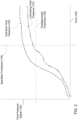
- the specified timeframe is at least 15 seconds (as indicated by the vertical dotted line).
- the specified timeframe 155 may be variable wherein the timeframe 155 is compensated for either the ambient temperature, an altitude, or both.
- Work machines can operate in temperature extremes wherein both high and low temperatures can affect the performance of hydraulic and lubricating fluids. Cold temperatures can affect the viscosity of the fluids in a hydraulic system. Lower temperatures may increase the viscosity of hydraulic fluid and oil wherein the fluids behave as a thicker fluid. If the ambient temperature or work machine temperature impacts the viscosity substantially, the fluid will not behave as intended.
- the specified timeframe 155 will lengthen.
- low atmospheric pressure at high altitudes may subject the reservoir in hydraulic systems to insufficient pressure to supply the pump at rated flow conditions.
- the specified timeframe 155 will lengthen to allow for hydraulic fluid and oil to flow normally.
- the predetermined threshold 150 may be variable by compensating for either the ambient temperature, an altitude, or both.
- the safety lock 136 may comprise of one or more of an engine hood lock 162, a service door lock 164, and a cab position lock 166.
- Safety lock configurations will vary based on the work machine. For example, in the present embodiment of a compact track loader, the boom arms must be secured in a lowered position prior to starting the work machine 102.
- a remote operator will not have direct visibility of personnel being in or around the work machine during instances such as repair, workers being present, or individuals trespassing. Furthermore, a remote operator may not be able to determine if the work machine was tampered with.
- the safety lock check will verify if service doors, engine hoods, and panels are in a locked or secured position. This may be verified by sensors.
- the remote start process may only continue to proceed if the conditions are satisfied. If the controller 110 determines that a requirement is not met, the controller 110 may halt the process of remote starting and notify the communication device 104.
- Alert signals 168 may include light indicators 168a, text messages 168b, audio calls 168c, digital pictorials 168d and a camera view 168e, for example.
- the communication device 104 sends an alert signal 168 to a remote user interface 170 on a remote device 114 if the controller 110 outputs an engine start signal 140.
- the controller 110 may further initiate monitoring the fluid pressure 120 upon the engine reaching a minimum idle speed 172.
- FIG. 3 discloses a method 300 of remotely starting a work machine.
- the communication device 104 receives a remote start signal 112 from the remote device 114.
- the remote start signal 112 may be operator initiated, responsive to a timed program instruction, dependent on specific conditions (e.g. the distance between the remote device and the communication device), and part of a sequence of events in a worksite plan.
- the communication device 104 outputs a wake signal upon 116 receiving the remote start signal 112. Once the wake signal 116 is received, in step 306, the controller 110 confirms a lock status 138 of one or more safety locks 136 on the work machine 102.
- step 308 if the controller 110 fails to confirm the lock status 138, an alert signal 168 may be sent to a remote user interface 170 on the remote device 114.
- the controller 110 outputs an engine start signal 140 to the engine starter subsystem 106, and thereby initiating an engine start.
- the controller in step 312, then monitors fluid pressure signal 120 from the fluid pressure sensor 108 from one or more work machine subsystems 122.
- step 314 if the fluid pressure signal 120 remains below a predetermined threshold 150 after a specified timeframe 155, the controller 110 will output an engine stop signal 145, and subsequently send an alert signal 168 to a remote user interface 170 on the remote device 114 in step 314.
- the predetermined threshold 150 of the pressure for a fluid is be pre-established.
- This predetermined threshold value may be depend on one or more of a fluid type, work machine subsystem 122 and the type of work machine 102.
- the hydraulic fluid of the hydraulic system 124 may have a first threshold pressure and the lubricating fluid from a transmission system 132 may have a second threshold pressure different than the first threshold pressure.
- the predetermined threshold values for each fluid are stored in the controller memory. It is contemplated that the threshold pressure value could defined by a percentage of initial pressure of the fluid or defined by absolute pressure values.
- the first specified timeframe 155 may be defined as the time elapsed after the controller 110 detects the engine start and could be predetermined based on the type of work machine subsystems 122, type of fluids used and type of the work machine 102.
- the first specified timeframe 155 may be stored in the controller memory and could be changed via the operator display or the remote device.
- the communication device 104 sends an alert signal to a remote user interface if the controller outputs an engine stop signal as shown in step 318.
- the controller 110 may continue starting the work machine 102.
Landscapes
- Engineering & Computer Science (AREA)
- Mechanical Engineering (AREA)
- General Engineering & Computer Science (AREA)
- Combustion & Propulsion (AREA)
- Chemical & Material Sciences (AREA)
- General Health & Medical Sciences (AREA)
- Signal Processing (AREA)
- Computer Networks & Wireless Communication (AREA)
- Medical Informatics (AREA)
- Health & Medical Sciences (AREA)
- Computing Systems (AREA)
- Operation Control Of Excavators (AREA)
- Control Of Vehicle Engines Or Engines For Specific Uses (AREA)
Abstract
Description
- The present disclosure relates to system and method of remotely starting a work machine.
- In the construction, agriculture, mining, and forestry industries, many different types of work machines operate to perform different tasks in a varying work environments. This includes off-road and on-road, high and low altitudes, and extreme temperature ranges. In some instances, starting the work machine at the beginning of a work shift may result in delays, for example, to properly warm the work machine. Variations in environmental conditions can impact how fluids respond in starting up the work machine. Current methods may use fluid level sensors. However, this can be misleading as levels may be impacted by changes in slope. Furthermore, current methods require starting the prime mover to run on idle for several minutes prior to confirming readiness. However, this can lead to unnecessary stresses on the work machine if a leak, insufficient fluid levels, or a hose for attachments is improperly coupled to the work machine. Therein lies an opportunity to shorten the timeframe for work machine readiness.
- This summary is provided to introduce a selection of concepts that are further described below in the detailed description and accompanying drawings. This summary is not intended to identify key or essential features of the appended claims, nor is it intended to be used as an aid in determining the scope of the appended claims.
- The present disclosure relates to a system and method of remotely starting a work machine. The remote start system comprises a communication device, an engine starter subsystem, at least one fluid pressure sensor, and a controller. The communication device is configured to receive a remote start signal and outputs a wake signal upon receiving the remote start signal. The engine starter subsystem is configured to initiate an engine start. Th fluid pressure sensor senses the fluid pressure on the work machine subsystem. The controller has a non-transitory computer readable medium with a program instruction to remotely start the work machine. The program instructions, when executed, cause the processor of the controller to do the following steps. The controller receives the wake signal; confirms a lock status of the safety lock of the work machine; outputs an engine start signal to the engine starter subsystem upon confirming the lock status; receives a fluid pressure signal from the fluid pressure sensor; and outputs an engine stop signal if the fluid pressure signal is below a predetermined threshold after a specified timeframe. The work machine subsystem comprises one or more of the hydraulic system and the transmission system.
- The specified timeframe is at least 15 seconds. The specified timeframe may be variable and compensates for one or more of an ambient temperature and an altitude. The predetermined threshold is variable by compensating for one or more of an ambient temperature and an altitude.
- The safety lock may comprise one or more of an engine hood lock, a service door lock, and a cab position lock. The communication device may send an alert signal to a remote user interface if the controller fails to confirm the lock status of the safety lock.
- The communication device may send an alert signal to a remote user interface if the controller outputs an engine stop signal. The communication device may send an alert signal to a remote user interface if the controller outputs an engine start signal. The controller may receive the fluid pressure signal upon the engine reaching a minimum idle speed.
- According to an aspect of the present disclosure, a method of remotely starting a work machine comprises the following steps. In a first step, a remote start signal is received by a communication device from a remote device. Next, the communication device outputs a wake signal upon receiving the remote start signal. The controller then receives the wake signal and confirms a lock status of a safety lock on the work machine. Next the controller outputs an engine start signal to the start subsystem upon confirming the lock status, monitors a fluid pressure signal from a fluid pressure sensor, and outputs an engine stop signal if the fluid pressure signal is below a predetermined threshold after a specified timeframe.
- Other features and aspects of the disclosure will become apparent by consideration of the following detailed description and accompanying drawings.
-
-
FIG. 1 is schematic representation of an exemplary remote start system; -
FIG. 2 is a graph illustrating monitoring of various fluid pressures over time; and -
FIG. 3 is a flowchart outlining a method of remotely starting a work machine. - Before any embodiments are explained in detail, it is to be understood that the disclosure is not limited in its application to the details of construction and the arrangement of components set forth in the following description or illustrated in the following drawings. The disclosure is capable of supporting other embodiments and of being practiced or of being carried out in various ways. Also, it is to be understood that the phraseology and terminology used herein is for the purpose of description and should not be regarded as limiting.
- As used herein, unless otherwise limited or modified, lists with elements that are separated by conjunctive terms (e.g., "and") and that are also preceded by the phrase "one or more of' or "at least one of" indicate configurations or arrangements that potentially include individual elements of the list, or any combination thereof. For example, "at least one of A, B, and C" or "one or more of A, B, and C" indicates the possibilities of only A, only B, only C, or any combination of two or more of A, B, and C (e.g., A and B; B and C; A and C; or A, B, and C).
- As used herein, the term "controller" is a computing device including a processor and a memory. The "controller" may be a single device or alternatively multiple devices. The controller may further refer to any hardware, software, firmware, electronic control component, processing logic, processing device, individually or in any combination, including without limitation: application specific integrated circuit (ASIC), an electronic circuit, a processor (shared, dedicated, or group) and memory that executes one or more software or firmware programs, a combinational logic circuit, and/or other suitable components that provide the described functionality.
- The term "processor" is described and shown as a single processor. However, two or more processors can be used according to particular needs, desires, or particular implementations of the controller and the described functionality. The processor may be a component of the controller, a portion of the object detector, or alternatively a part of another device. Generally, the processor can execute instructions and can manipulate data to perform the operations of the controller, including operations using algorithms, methods, functions, processes, flows, and procedures as described in the present disclosure.
-
FIG. 1 is a schematic representation of the remote start system 100 for awork machine 102 as applied to a compact track loader. However, the system 100 can be applied to any work machine, including but not limited to, various construction, forestry, mining and agricultural work machines. - The remote start system 100 comprises a
communication device 104, anengine starter subsystem 106, at least one fluid pressure sensor 108, and acontroller 110. Thecommunication device 104 is configured to receive aremote start signal 112 from aremote device 114. Theremote device 114 may generally be associated with a future operator of the work machine located at a location remote from thework machine 102, or alternatively theremote device 114 may autonomously run through program instructions to safely remote start thework machine 102. Although not shown in detail, theremote device 114 may include a tablet computing device, a smart cellular phone, personal digital assistant, a laptop computing device, for example. In another scenario, theremote device 114 may be stationary, such as a terminal, or otherwise be located at a control center. - The
communication device 104 outputs a wake signal upon receiving aremote start signal 112 from theremote device 114. Theremote device 114 may communicate with thecommunication device 104 over a network. For example, theremote device 104 may achieve bidirectional communications with thework machine 102, and/or thecommunication device 104 over Bluetooth(R) or by utilizing a Wi-Fi standard, i.e., one or more of the 802.11 standards as defined by the Institute of Electrical and Electronics Engineers ("IEEE"), as is well known to those skilled in the art. Thus, theremote device 104 may include a Bluetooth(R) transceiver, a radio transceiver, a cellular transceiver, an LTE transceiver and/or a Wi-Fi transceiver. Theremote device 114 may employ various security protocols and techniques to ensure that appropriately secure communication with the work machine and/orcommunication device 104, of the remote start system 100. In another embodiment, thework machine 102 may include a GPS or other navigation system. The GPS may be used to determine the location of the work machine. The GPS may also receive data or information from theremote device 114 in order to determine the location and direction of travel of theremote device 114 relative to thecommunication device 104 on thework machine 102. Thecommunication device 104 may be configured to determine the exact or approximate distance between thecommunication device 104 and theremote device 114 and only initiate awake signal 116 upon theremote device 114 being in an acceptable range. - The
engine starter subsystem 106 is configured to initiate an engine start. Theengine start subsystem 106 may alternatively be configured to energize any form of a prime mover, such as internal combustion engines, fuel cells, gas turbines, electric motors, etc. - The fluid pressure sensor 108 senses a
fluid pressure 120 on awork machine subsystem 122.Work machine subsystems 122 may include ahydraulic system 124 and atransmission system 132. Various sensors on the work machine may measure the pressure, temperature, or the viscosity of the fluids within thework machine 102. The data acquired from measuring the multiple parameters is sent to thecontroller 110 for processing and monitoring. It is contemplated that thecontroller 110 may monitor the plurality of parameters of the fluids at one or more locations of the fluid paths. For example thehydraulic fluid pressure 125 may be measured with a hydraulic pressure sensor 126 at the outlet of the hydraulic pump or at the control valve etc. Similarly, the lubricatingfluid pressure 133 may be measured with a lubricating pressure sensor 134 located at the exit of lubrication pump, in the lubricating supply lines or at any other appropriate location. - The
controller 110 has a non-transitory computer readable medium that includes program instructions to remotely start the work machine. The program instructions when executed cause a processor of thecontroller 110 to receive thewake signal 116, confirm a lock status 138 of a safety lock 136 on thework machine 102, output an engine start signal 140 to theengine starter subsystem 106 upon confirming the lock status 138, receive a fluid pressure signal 120 from the fluid pressure sensor 108, and output anengine stop signal 145 if thefluid pressure signal 120 is below a predetermined threshold after a specifiedtimeframe 155. - Now referring to
FIG. 2 with continued reference toFIG. 1 , an exemplary graph 156 of the fluid pressure signal 120 overtime 160 is shown. The specified timeframe is at least 15 seconds (as indicated by the vertical dotted line). The specifiedtimeframe 155 may be variable wherein thetimeframe 155 is compensated for either the ambient temperature, an altitude, or both. Work machines can operate in temperature extremes wherein both high and low temperatures can affect the performance of hydraulic and lubricating fluids. Cold temperatures can affect the viscosity of the fluids in a hydraulic system. Lower temperatures may increase the viscosity of hydraulic fluid and oil wherein the fluids behave as a thicker fluid. If the ambient temperature or work machine temperature impacts the viscosity substantially, the fluid will not behave as intended. For example, on startup, oil with higher-than-normal viscosity may not distribute evenly around critical components quickly enough to pressurize the system sufficiently. Therefore, in the exemplary scenario of cold temperatures, the specifiedtimeframe 155 will lengthen. Similarly, low atmospheric pressure at high altitudes may subject the reservoir in hydraulic systems to insufficient pressure to supply the pump at rated flow conditions. In the exemplary scenario of high altitudes, the specifiedtimeframe 155 will lengthen to allow for hydraulic fluid and oil to flow normally. In the same way, thepredetermined threshold 150 may be variable by compensating for either the ambient temperature, an altitude, or both. - The safety lock 136 may comprise of one or more of an engine hood lock 162, a service door lock 164, and a cab position lock 166. Safety lock configurations will vary based on the work machine. For example, in the present embodiment of a compact track loader, the boom arms must be secured in a lowered position prior to starting the
work machine 102. Furthermore, a remote operator will not have direct visibility of personnel being in or around the work machine during instances such as repair, workers being present, or individuals trespassing. Furthermore, a remote operator may not be able to determine if the work machine was tampered with. The safety lock check will verify if service doors, engine hoods, and panels are in a locked or secured position. This may be verified by sensors. Alternatively, this may be verified by an onboard image system or other methods of confirmation. The remote start process may only continue to proceed if the conditions are satisfied. If thecontroller 110 determines that a requirement is not met, thecontroller 110 may halt the process of remote starting and notify thecommunication device 104. - The
communication device 104 may then send an alert signal to a remote user interface 170 if thecontroller 110 fails to confirm the lock status 138 of the safety lock 136. Alert signals 168 may include light indicators 168a, text messages 168b, audio calls 168c, digital pictorials 168d and a camera view 168e, for example. - The
communication device 104 sends analert signal 168 to a remote user interface 170 on aremote device 114 if thecontroller 110 outputs anengine start signal 140. - The
controller 110 may further initiate monitoring thefluid pressure 120 upon the engine reaching a minimumidle speed 172. -
FIG. 3 discloses amethod 300 of remotely starting a work machine. In afirst step 302, thecommunication device 104 receives a remote start signal 112 from theremote device 114. Theremote start signal 112 may be operator initiated, responsive to a timed program instruction, dependent on specific conditions (e.g. the distance between the remote device and the communication device), and part of a sequence of events in a worksite plan. Instep 304, thecommunication device 104 outputs a wake signal upon 116 receiving theremote start signal 112. Once thewake signal 116 is received, instep 306, thecontroller 110 confirms a lock status 138 of one or more safety locks 136 on thework machine 102. Instep 308, if thecontroller 110 fails to confirm the lock status 138, analert signal 168 may be sent to a remote user interface 170 on theremote device 114. Alternatively, if the lock status 138 is confirmed, instep 310 thecontroller 110 outputs an engine start signal 140 to theengine starter subsystem 106, and thereby initiating an engine start. The controller, instep 312, then monitors fluid pressure signal 120 from the fluid pressure sensor 108 from one or morework machine subsystems 122. Instep 314, if the fluid pressure signal 120 remains below apredetermined threshold 150 after a specifiedtimeframe 155, thecontroller 110 will output anengine stop signal 145, and subsequently send analert signal 168 to a remote user interface 170 on theremote device 114 instep 314. In a first embodiment, thepredetermined threshold 150 of the pressure for a fluid is be pre-established. This predetermined threshold value may be depend on one or more of a fluid type,work machine subsystem 122 and the type ofwork machine 102. For example, the hydraulic fluid of thehydraulic system 124 may have a first threshold pressure and the lubricating fluid from atransmission system 132 may have a second threshold pressure different than the first threshold pressure. The predetermined threshold values for each fluid are stored in the controller memory. It is contemplated that the threshold pressure value could defined by a percentage of initial pressure of the fluid or defined by absolute pressure values. - The first specified
timeframe 155 may be defined as the time elapsed after thecontroller 110 detects the engine start and could be predetermined based on the type ofwork machine subsystems 122, type of fluids used and type of thework machine 102. The first specifiedtimeframe 155 may be stored in the controller memory and could be changed via the operator display or the remote device. Instep 316, thecommunication device 104 sends an alert signal to a remote user interface if the controller outputs an engine stop signal as shown instep 318. Alternatively, as shown instep 320, thecontroller 110 may continue starting thework machine 102. - Various features of the disclosure are set forth in the following claims.
Claims (11)
- A remote start system of a work machine, the remote start system comprising:a communication device configured to receive a remote start signal, the communication device outputting a wake signal upon receiving the remote start signal;an engine starter subsystem configured to initiate an engine start;at least one fluid pressure sensor for sensing a fluid pressure on a work machine subsystem; anda controller having a non-transitory computer readable medium with a program instruction to remotely start the work machine, the program instructions when executed causing a processor of the controller to:receive the wake signal;confirm a lock status of a safety lock of the work machine;output an engine start signal to the engine starter subsystem upon confirming the lock status;receive a fluid pressure signal from the fluid pressure sensor; andoutput an engine stop signal if the fluid pressure signal is below a predetermined threshold after a specified timeframe.
- A method of remotely starting a work machine, the method comprising:receiving a remote start signal by a communication device from a remote device;outputting a wake signal by the communication device upon receiving the remote start signal;receiving the wake signal by a controller;confirming a lock status by the controller of a safety lock of the work machine;outputting an engine start signal to an engine starter subsystem upon confirming the lock status;monitoring a fluid pressure signal from a fluid pressure sensor, the fluid pressure sensor sensing a fluid pressure on a work machine subsystem; andoutputting an engine stop signal if the fluid pressure signal is below a predetermined threshold after a specified timeframe.
- The remote start system of claim 1 or the method of remotely starting a work machine of claim 2, wherein the work machine subsystem comprises one or more of a hydraulic system and a transmission system.
- The remote start system of claim 1 or any claim dependent thereon, or the method of remotely starting a work machine of claim 2 or any claim dependent thereon, wherein the specified timeframe is at least 15 seconds.
- The remote start system of claim 1 or any claim dependent thereon, or the method of remotely starting a work machine of claim 2 or any claim dependent thereon, wherein the specified timeframe is variable by compensating for one or more of an ambient temperature and an altitude.
- The remote start system of claim 1 or any claim dependent thereon, or the method of remotely starting a work machine of claim 2 or any claim dependent thereon, wherein the predetermine threshold is variable and compensating for one or more of an ambient temperature and an altitude.
- The remote start system of claim 1 or any claim dependent thereon, or the method of remotely starting a work machine of claim 2 or any claim dependent thereon, wherein the safety lock comprises one or more of an engine hood lock, service door lock, and a cab position lock.
- The remote start system of claim 1 or any claim dependent thereon, or the method of remotely starting a work machine of claim 2 or any claim dependent thereon, wherein the communication device sends an alert signal to a remote user interface and outputs an engine stop signal if the controller fails to confirm the lock status of the safety lock.
- The remote start system of claim 1 or any claim dependent thereon, or the method of remotely starting a work machine of claim 2 or any claim dependent thereon, wherein the communication device sends an alert signal to a remote user interface if the controller outputs the engine stop signal.
- The remote start system of claim 1 or any claim dependent thereon, or the method of remotely starting a work machine of claim 2 or any claim dependent thereon, wherein the communication device sends an alert signal to a remote user interface if the controller outputs the engine start signal.
- The remote start system of claim 1 or any claim dependent thereon, or the method of remotely starting a work machine of claim 2 or any claim dependent thereon, wherein the controller receives the fluid pressure signal upon an engine reaching a minimum idle speed.
Applications Claiming Priority (1)
| Application Number | Priority Date | Filing Date | Title |
|---|---|---|---|
| US17/648,358 US12304423B2 (en) | 2022-01-19 | 2022-01-19 | Remote start system and method for a work machine |
Publications (2)
| Publication Number | Publication Date |
|---|---|
| EP4215743A1 true EP4215743A1 (en) | 2023-07-26 |
| EP4215743B1 EP4215743B1 (en) | 2025-11-19 |
Family
ID=84943767
Family Applications (1)
| Application Number | Title | Priority Date | Filing Date |
|---|---|---|---|
| EP23151341.7A Active EP4215743B1 (en) | 2022-01-19 | 2023-01-12 | Remote start system and method for a work machine |
Country Status (3)
| Country | Link |
|---|---|
| US (1) | US12304423B2 (en) |
| EP (1) | EP4215743B1 (en) |
| FI (1) | FI4215743T3 (en) |
Families Citing this family (2)
| Publication number | Priority date | Publication date | Assignee | Title |
|---|---|---|---|---|
| US20240309592A1 (en) * | 2023-03-15 | 2024-09-19 | Caterpillar Paving Products Inc. | Material handling system |
| CN117449368A (en) * | 2023-10-20 | 2024-01-26 | 三一重机有限公司 | Control method of working machine and working machine |
Citations (3)
| Publication number | Priority date | Publication date | Assignee | Title |
|---|---|---|---|---|
| US5990800A (en) * | 1994-11-16 | 1999-11-23 | Komatsu Ltd. | Remote engine starting and stopping device for construction machine |
| GB2506134A (en) * | 2012-09-20 | 2014-03-26 | Perkins Engines Co Ltd | Priming engine lubricant pressure before starting the engine |
| US10018171B1 (en) * | 2017-05-17 | 2018-07-10 | Deere & Company | Work vehicle start system and method with virtual walk-around for authorizing remote start |
Family Cites Families (7)
| Publication number | Priority date | Publication date | Assignee | Title |
|---|---|---|---|---|
| DE3735123A1 (en) * | 1987-10-16 | 1989-06-29 | Hartmann & Laemmle | HYDRAULIC DRIVE DEVICE |
| JP5477137B2 (en) * | 2010-04-15 | 2014-04-23 | 株式会社デンソー | Engine automatic stop / restart control system |
| US9193353B2 (en) * | 2013-10-30 | 2015-11-24 | GM Global Technology Operations LLC | Systems and methods for controlling an automatic transmission during a flying engine start using a flow accumulator |
| CN108137160B (en) | 2015-09-30 | 2021-10-01 | 庞巴迪公司 | Method and system for presenting the operating state of an aircraft engine |
| US10132259B1 (en) | 2017-05-17 | 2018-11-20 | Deere & Company | Work vehicle start system and method with engine cycling |
| US11536009B2 (en) | 2019-07-26 | 2022-12-27 | Deere & Company | System for detecting locking pin engagement of an implement |
| JP7294168B2 (en) * | 2020-01-29 | 2023-06-20 | トヨタ自動車株式会社 | CONTROL DEVICE, VEHICLE, CONTROL SYSTEM, PROGRAM AND CONTROL METHOD |
-
2022
- 2022-01-19 US US17/648,358 patent/US12304423B2/en active Active
-
2023
- 2023-01-12 FI FIEP23151341.7T patent/FI4215743T3/en active
- 2023-01-12 EP EP23151341.7A patent/EP4215743B1/en active Active
Patent Citations (3)
| Publication number | Priority date | Publication date | Assignee | Title |
|---|---|---|---|---|
| US5990800A (en) * | 1994-11-16 | 1999-11-23 | Komatsu Ltd. | Remote engine starting and stopping device for construction machine |
| GB2506134A (en) * | 2012-09-20 | 2014-03-26 | Perkins Engines Co Ltd | Priming engine lubricant pressure before starting the engine |
| US10018171B1 (en) * | 2017-05-17 | 2018-07-10 | Deere & Company | Work vehicle start system and method with virtual walk-around for authorizing remote start |
Also Published As
| Publication number | Publication date |
|---|---|
| FI4215743T3 (en) | 2026-01-21 |
| US12304423B2 (en) | 2025-05-20 |
| EP4215743B1 (en) | 2025-11-19 |
| US20230226999A1 (en) | 2023-07-20 |
Similar Documents
| Publication | Publication Date | Title |
|---|---|---|
| EP4215743B1 (en) | Remote start system and method for a work machine | |
| US20170092019A1 (en) | Real-time vehicle operation monitoring system and method based on mobile terminal | |
| JP4853921B2 (en) | Aircraft diagnosis system | |
| US20180107473A1 (en) | Determining whether to install a vehicle system update in a vehicle | |
| US9630590B2 (en) | Control method, device and system for a vehicle | |
| US5646341A (en) | Apparatus and method for diagnosing an engine using an oil pressure model | |
| EP1237385A2 (en) | Vehicle diagnostic system | |
| US6438471B1 (en) | Repair and maintenance support system and a car corresponding to the system | |
| KR20010103907A (en) | Automotive self diagnostic System for using communication network | |
| CN104359476A (en) | Automobile positioning and navigation device, automobile positioning and navigation system and automobile positioning and navigation method | |
| CN104832241A (en) | Engine lubrication control device, system and control method | |
| US10011225B2 (en) | System and method for detecting at least one replacement component of a device | |
| US9174648B2 (en) | System for using short text messaging for remote diagnostic | |
| KR100866617B1 (en) | Vehicle driving information management system and method | |
| CN110985127A (en) | Mobile terminal working method and system of surface mine unmanned transportation system | |
| CN102508468B (en) | Debugging method of comprehensive debugging instrument for vehicle-mounted information terminal | |
| JP2011052435A (en) | Method for confirming compatibility of work machine | |
| US20150073649A1 (en) | Managing diagnostic trouble codes in a vehicle | |
| EP2490038A2 (en) | System and method for tracking the location of construction equipment | |
| WO2017008608A1 (en) | Cloud service based security information acquisition method for mobile terminal, terminal and storage medium, cloud service based security information delivery method for mobile terminal, and server | |
| US10055589B2 (en) | Systems and methods for validating auxiliary power unit or components by secure pin one time password | |
| CN115512472B (en) | Information matching method and device, electronic equipment and storage medium | |
| KR20090048291A (en) | Vehicle driving information management system and method | |
| CN117707112A (en) | Fault diagnosis method, system, equipment and storage medium | |
| KR101922222B1 (en) | Remote diagnosis system of construction equipment |
Legal Events
| Date | Code | Title | Description |
|---|---|---|---|
| PUAI | Public reference made under article 153(3) epc to a published international application that has entered the european phase |
Free format text: ORIGINAL CODE: 0009012 |
|
| STAA | Information on the status of an ep patent application or granted ep patent |
Free format text: STATUS: THE APPLICATION HAS BEEN PUBLISHED |
|
| AK | Designated contracting states |
Kind code of ref document: A1 Designated state(s): AL AT BE BG CH CY CZ DE DK EE ES FI FR GB GR HR HU IE IS IT LI LT LU LV MC ME MK MT NL NO PL PT RO RS SE SI SK SM TR |
|
| STAA | Information on the status of an ep patent application or granted ep patent |
Free format text: STATUS: REQUEST FOR EXAMINATION WAS MADE |
|
| 17P | Request for examination filed |
Effective date: 20240126 |
|
| RBV | Designated contracting states (corrected) |
Designated state(s): AL AT BE BG CH CY CZ DE DK EE ES FI FR GB GR HR HU IE IS IT LI LT LU LV MC ME MK MT NL NO PL PT RO RS SE SI SK SM TR |
|
| STAA | Information on the status of an ep patent application or granted ep patent |
Free format text: STATUS: EXAMINATION IS IN PROGRESS |
|
| 17Q | First examination report despatched |
Effective date: 20250128 |
|
| GRAP | Despatch of communication of intention to grant a patent |
Free format text: ORIGINAL CODE: EPIDOSNIGR1 |
|
| STAA | Information on the status of an ep patent application or granted ep patent |
Free format text: STATUS: GRANT OF PATENT IS INTENDED |
|
| INTG | Intention to grant announced |
Effective date: 20250716 |
|
| GRAS | Grant fee paid |
Free format text: ORIGINAL CODE: EPIDOSNIGR3 |
|
| GRAA | (expected) grant |
Free format text: ORIGINAL CODE: 0009210 |
|
| STAA | Information on the status of an ep patent application or granted ep patent |
Free format text: STATUS: THE PATENT HAS BEEN GRANTED |
|
| AK | Designated contracting states |
Kind code of ref document: B1 Designated state(s): AL AT BE BG CH CY CZ DE DK EE ES FI FR GB GR HR HU IE IS IT LI LT LU LV MC ME MK MT NL NO PL PT RO RS SE SI SK SM TR |
|
| REG | Reference to a national code |
Ref country code: CH Ref legal event code: F10 Free format text: ST27 STATUS EVENT CODE: U-0-0-F10-F00 (AS PROVIDED BY THE NATIONAL OFFICE) Effective date: 20251119 Ref country code: GB Ref legal event code: FG4D |
|
| REG | Reference to a national code |
Ref country code: DE Ref legal event code: R096 Ref document number: 602023008622 Country of ref document: DE |
|
| REG | Reference to a national code |
Ref country code: IE Ref legal event code: FG4D |
|
| REG | Reference to a national code |
Ref country code: FI Ref legal event code: FGE |
|
| REG | Reference to a national code |
Ref country code: NL Ref legal event code: MP Effective date: 20251119 |
|
| PG25 | Lapsed in a contracting state [announced via postgrant information from national office to epo] |
Ref country code: ES Free format text: LAPSE BECAUSE OF FAILURE TO SUBMIT A TRANSLATION OF THE DESCRIPTION OR TO PAY THE FEE WITHIN THE PRESCRIBED TIME-LIMIT Effective date: 20251119 |
|
| REG | Reference to a national code |
Ref country code: LT Ref legal event code: MG9D |
|
| PG25 | Lapsed in a contracting state [announced via postgrant information from national office to epo] |
Ref country code: NO Free format text: LAPSE BECAUSE OF FAILURE TO SUBMIT A TRANSLATION OF THE DESCRIPTION OR TO PAY THE FEE WITHIN THE PRESCRIBED TIME-LIMIT Effective date: 20260219 |
|
| PGFP | Annual fee paid to national office [announced via postgrant information from national office to epo] |
Ref country code: DE Payment date: 20260128 Year of fee payment: 4 |
|
| PG25 | Lapsed in a contracting state [announced via postgrant information from national office to epo] |
Ref country code: AT Free format text: LAPSE BECAUSE OF FAILURE TO SUBMIT A TRANSLATION OF THE DESCRIPTION OR TO PAY THE FEE WITHIN THE PRESCRIBED TIME-LIMIT Effective date: 20251119 Ref country code: HR Free format text: LAPSE BECAUSE OF FAILURE TO SUBMIT A TRANSLATION OF THE DESCRIPTION OR TO PAY THE FEE WITHIN THE PRESCRIBED TIME-LIMIT Effective date: 20251119 |
|
| PGFP | Annual fee paid to national office [announced via postgrant information from national office to epo] |
Ref country code: AT Payment date: 20260301 Year of fee payment: 4 |
|
| PGFP | Annual fee paid to national office [announced via postgrant information from national office to epo] |
Ref country code: FI Payment date: 20260126 Year of fee payment: 4 |
|
| REG | Reference to a national code |
Ref country code: AT Ref legal event code: MK05 Ref document number: 1859015 Country of ref document: AT Kind code of ref document: T Effective date: 20251119 |
|
| PG25 | Lapsed in a contracting state [announced via postgrant information from national office to epo] |
Ref country code: NL Free format text: LAPSE BECAUSE OF FAILURE TO SUBMIT A TRANSLATION OF THE DESCRIPTION OR TO PAY THE FEE WITHIN THE PRESCRIBED TIME-LIMIT Effective date: 20251119 |
|
| PG25 | Lapsed in a contracting state [announced via postgrant information from national office to epo] |
Ref country code: RS Free format text: LAPSE BECAUSE OF FAILURE TO SUBMIT A TRANSLATION OF THE DESCRIPTION OR TO PAY THE FEE WITHIN THE PRESCRIBED TIME-LIMIT Effective date: 20260219 |
|
| PG25 | Lapsed in a contracting state [announced via postgrant information from national office to epo] |
Ref country code: IS Free format text: LAPSE BECAUSE OF FAILURE TO SUBMIT A TRANSLATION OF THE DESCRIPTION OR TO PAY THE FEE WITHIN THE PRESCRIBED TIME-LIMIT Effective date: 20260319 |
|
| PG25 | Lapsed in a contracting state [announced via postgrant information from national office to epo] |
Ref country code: PT Free format text: LAPSE BECAUSE OF FAILURE TO SUBMIT A TRANSLATION OF THE DESCRIPTION OR TO PAY THE FEE WITHIN THE PRESCRIBED TIME-LIMIT Effective date: 20260319 |
|
| PG25 | Lapsed in a contracting state [announced via postgrant information from national office to epo] |
Ref country code: PL Free format text: LAPSE BECAUSE OF FAILURE TO SUBMIT A TRANSLATION OF THE DESCRIPTION OR TO PAY THE FEE WITHIN THE PRESCRIBED TIME-LIMIT Effective date: 20251119 |
|
| PG25 | Lapsed in a contracting state [announced via postgrant information from national office to epo] |
Ref country code: LV Free format text: LAPSE BECAUSE OF FAILURE TO SUBMIT A TRANSLATION OF THE DESCRIPTION OR TO PAY THE FEE WITHIN THE PRESCRIBED TIME-LIMIT Effective date: 20251119 |
|
| PG25 | Lapsed in a contracting state [announced via postgrant information from national office to epo] |
Ref country code: BG Free format text: LAPSE BECAUSE OF FAILURE TO SUBMIT A TRANSLATION OF THE DESCRIPTION OR TO PAY THE FEE WITHIN THE PRESCRIBED TIME-LIMIT Effective date: 20251119 |