EP4215736A2 - Active flow control system - Google Patents
Active flow control system Download PDFInfo
- Publication number
- EP4215736A2 EP4215736A2 EP23152759.9A EP23152759A EP4215736A2 EP 4215736 A2 EP4215736 A2 EP 4215736A2 EP 23152759 A EP23152759 A EP 23152759A EP 4215736 A2 EP4215736 A2 EP 4215736A2
- Authority
- EP
- European Patent Office
- Prior art keywords
- flow control
- control devices
- flow
- fluid
- downstream
- Prior art date
- Legal status (The legal status is an assumption and is not a legal conclusion. Google has not performed a legal analysis and makes no representation as to the accuracy of the status listed.)
- Granted
Links
Images
Classifications
-
- G—PHYSICS
- G05—CONTROLLING; REGULATING
- G05D—SYSTEMS FOR CONTROLLING OR REGULATING NON-ELECTRIC VARIABLES
- G05D7/00—Control of flow
- G05D7/06—Control of flow characterised by the use of electric means
- G05D7/0617—Control of flow characterised by the use of electric means specially adapted for fluid materials
- G05D7/0629—Control of flow characterised by the use of electric means specially adapted for fluid materials characterised by the type of regulator means
- G05D7/0635—Control of flow characterised by the use of electric means specially adapted for fluid materials characterised by the type of regulator means by action on throttling means
- G05D7/0641—Control of flow characterised by the use of electric means specially adapted for fluid materials characterised by the type of regulator means by action on throttling means using a plurality of throttling means
- G05D7/0664—Control of flow characterised by the use of electric means specially adapted for fluid materials characterised by the type of regulator means by action on throttling means using a plurality of throttling means the plurality of throttling means being arranged for the control of a plurality of diverging flows from a single flow
-
- F—MECHANICAL ENGINEERING; LIGHTING; HEATING; WEAPONS; BLASTING
- F02—COMBUSTION ENGINES; HOT-GAS OR COMBUSTION-PRODUCT ENGINE PLANTS
- F02C—GAS-TURBINE PLANTS; AIR INTAKES FOR JET-PROPULSION PLANTS; CONTROLLING FUEL SUPPLY IN AIR-BREATHING JET-PROPULSION PLANTS
- F02C7/00—Features, components parts, details or accessories, not provided for in, or of interest apart form groups F02C1/00 - F02C6/00; Air intakes for jet-propulsion plants
- F02C7/22—Fuel supply systems
- F02C7/232—Fuel valves; Draining valves or systems
-
- F—MECHANICAL ENGINEERING; LIGHTING; HEATING; WEAPONS; BLASTING
- F02—COMBUSTION ENGINES; HOT-GAS OR COMBUSTION-PRODUCT ENGINE PLANTS
- F02C—GAS-TURBINE PLANTS; AIR INTAKES FOR JET-PROPULSION PLANTS; CONTROLLING FUEL SUPPLY IN AIR-BREATHING JET-PROPULSION PLANTS
- F02C9/00—Controlling gas-turbine plants; Controlling fuel supply in air- breathing jet-propulsion plants
- F02C9/26—Control of fuel supply
-
- F—MECHANICAL ENGINEERING; LIGHTING; HEATING; WEAPONS; BLASTING
- F16—ENGINEERING ELEMENTS AND UNITS; GENERAL MEASURES FOR PRODUCING AND MAINTAINING EFFECTIVE FUNCTIONING OF MACHINES OR INSTALLATIONS; THERMAL INSULATION IN GENERAL
- F16K—VALVES; TAPS; COCKS; ACTUATING-FLOATS; DEVICES FOR VENTING OR AERATING
- F16K31/00—Actuating devices; Operating means; Releasing devices
- F16K31/004—Actuating devices; Operating means; Releasing devices actuated by piezoelectric means
Definitions
- the present disclosure relates to flow control devices.
- Engine fuel controllers typically include passive hydro-mechanical components, such as pressure regulating valves, minimum pressure valves, and the like. However, the design of these components may not be changed during operation, without shutting down an engine, for example. Active components used in engine fuel controllers can include electro-mechanical based devices like electro-hydraulic servo valves and solenoids, but such devices may not operate quickly enough to provide the desired response time.
- a system for active flow control includes one or more flow control devices configured to control flow between a fluid source and a fluid destination, and a control module configured to control a flow area of each of the one or more flow control devices with fluid provided from the fluid source flowing to the fluid destination through the one or more flow control devices.
- one or more actuators are operatively connected between the one or more flow control devices and the control module, wherein the control module is configured to control the flow area of the one or more flow control devices via the one or more actuators.
- the one or more actuators can include a piezoelectric actuator.
- the fluid destination can include an actuation system. In certain embodiments, the fluid destination can include a combustor of an engine. In certain embodiments, the fluid destination can include a bypass return flow system. In embodiments, the one or more flow control devices can be included in a single interconnected fluid system, where the fluid destination includes one or more of an actuation system, a combustor of an engine, and/or a bypass return flow system, or any combination thereof.
- one or more pressure sensors operatively connected upstream and/or downstream of the one or more flow control devices configured to sense and output a pressure signal indicative of a pressure in the flow system upstream and/or downstream of the one or more flow control devices.
- the control module can be configured to control the one or more flow control devices based at least in part on the signal indicative of a pressure in the flow system upstream and/or downstream of the one or more flow control devices.
- a control module for active flow control can include computer readable instructions configured to cause the control module to control one or more actuators operatively connected to one or more flow control devices to adjust a flow area of the one or more flow control devices while fluid is provided from a fluid source to a fluid destination through the one or more flow control devices.
- the computer readable instructions can be configured to cause the control module to control the one or more actuators without stopping flow through the one or more flow control devices.
- the one or more actuators can include a piezoelectric actuator.
- control module can be configured to receive one or more signals indicative of a pressure in the flow system upstream and/or downstream of the one or more flow control devices from one or more pressure sensors operatively connected upstream and/or downstream of the one or more flow control devices.
- computer readable instructions can be configured to cause the control module to control the one or more flow control devices based at least in part on the signal indicative of a pressure in the flow system upstream and/or downstream of the one or more flow control devices.
- a method can include controlling one or more actuators operatively connected to one or more flow control devices to adjust a flow area of the one or more flow control devices while fluid is provided from a fluid source to a fluid destination through the one or more flow control devices.
- controlling can include, controlling the one or more actuators without stopping flow through the one or more flow control devices.
- the method can include, sensing a pressure upstream and/or downstream of the one or more flow control devices from one or more pressure sensors operatively connected upstream and/or downstream of the one or more flow control devices.
- controlling can further include, controlling the one or more flow control devices based at least in part on the signal indicative of a pressure upstream and/or downstream of the one or more flow control devices.
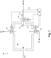
- FIG. 1 is a schematic diagram of a flow control system in accordance with this disclosure, showing one or more flow control devices disposed in the flow control system.
- FIG. 1 an illustrative view of an embodiment of a system in accordance with the disclosure is shown in Fig. 1 and is designated generally by reference character 100.
- a system 100 for active flow control can include one or more flow control devices 102 configured to control flow between a fluid source 104 and a fluid destination 106.
- a control module 108 can be configured to control a flow area of each of the one or more flow control devices 102 with fluid provided from the fluid source 104 flowing to the fluid destination 106 through the one or more flow control devices 102. More specifically, the control module 108 can be configured to control the one or more flow control devices 102 while fluid is flowing through the one or more flow control devices 102, and without stopping said fluid flow.
- one or more actuators 110 are operatively connected between the one or more flow control devices 102 and the control module 108, where the control module 108 is configured to control the flow area of the one or more flow control devices 102 via the one or more actuators 110.
- the one or more actuators 110 can include a piezoelectric actuator.
- the fluid destination 106 can include an actuation system 106a. In certain embodiments, the fluid destination 106 can include a combustor of an engine 106b. In certain embodiments, the fluid destination can include a bypass return flow system 106c. In embodiments, the one or more flow control devices 102 can be included in a single interconnected fluid system 200 (e.g., as shown), where the fluid destination 106 includes one or more of an actuation system 106a, a combustor of an engine 106b, and/or a bypass return flow system 106c, or any combination thereof.
- one or more pressure sensors 112 can be operatively connected upstream and/or downstream of the one or more flow control devices 102 configured to sense and output a pressure signal 114 indicative of a pressure in the flow system 200 upstream and/or downstream of the one or more flow control devices 102.
- the control module 108 can be configured to control the one or more flow control devices 102 based at least in part on the signal 114 indicative of a pressure in the flow system 200 upstream and/or downstream of the one or more flow control devices 102.
- a control module for active flow control can include computer readable instructions configured to cause the control module to control one or more actuators (e.g., actuators 110) operatively connected to one or more flow control devices (e.g., devices 102) to adjust a flow area of the one or more flow control devices while fluid is provided from a fluid source 104 to a fluid destination 106 through the one or more flow control devices.
- actuators e.g., actuators 110
- flow control devices e.g., devices 102
- the computer readable instructions can be configured to cause the control module to control the one or more actuators without stopping flow through the one or more flow control devices (e.g., without shutting down a pump or the flow system 200).
- the one or more actuators can include a piezoelectric actuator.
- control module 108 can be configured to receive one or more signals 114 indicative of a pressure in the flow system upstream and/or downstream of the one or more flow control devices from one or more pressure sensors operatively connected upstream and/or downstream of the one or more flow control devices 102. Accordingly, the computer readable instructions can be configured to cause the control module 108 to control the one or more flow control devices 102 based at least in part on the signal 114 indicative of a pressure in the flow system upstream and/or downstream of the one or more flow control devices.
- control module 108 and/or other components of system 100 can be or include both hard wired circuits that cause a logic (e.g. predictive) to be executed, and/or software-based components, for example, simple electric circuits employing analogue components, or the controller can include a CPU, a memory, machine readable instructions in the memory that when executed cause the CPU to perform a method or cause the control module 108 to perform a method, for example as described below.
- the control module 108 can utilize any suitable algorithm to control the one or more flow control devices 102 as provided herein.
- the algorithm could be constructed using the functionality as described above in addition to known general engineering principles as applied to the specific characteristics of each particular fuel system to which the technology of the present disclosure is applied.
- a method can include controlling one or more actuators (e.g., actuators 110) operatively connected to one or more flow control devices (e.g., devices 102) to adjust a flow area of the one or more flow control devices while fluid is provided from a fluid source to a fluid destination through the one or more flow control devices.
- controlling can include, controlling the one or more actuators without stopping flow through the one or more flow control devices (e.g., actively controlling the one or more flow control devices).
- the method can include, sensing a pressure upstream and/or downstream of the one or more flow control devices from one or more pressure sensors (e.g., sensors 112) operatively connected upstream and/or downstream of the one or more flow control devices.
- controlling can further include, controlling the one or more flow control devices based at least in part on the signal indicative of a pressure upstream and/or downstream of the one or more flow control devices.
- Typical flow control devices are hydro-mechanical flow control devices, but in certain instances, such devices may be slow acting, and may not be able to provide active control.
- Embodiments include electrically controlled flow control devices, which can provide fast moving, active control.
- Embodiments can include sensors, such as pressure sensors, configured to send pressure readings to control system, where the control system can then control the flow control devices based on the pressure readings.
- Embodiments can include additional sensors or, if desired for certain applications, traditional valving could be incorporated to work in conjunction with the actively controlled valves.
- a fluid destination can include a combustor of an engine, where a metering valve can be included between a fluid source and the combustor.
- a metering valve can be included between a fluid source and the combustor.
- Having an active controlled flow control device as provided herein could replace, or improve the existing metering valve.
- the fluid destination includes an actuation system or bypass line.
- active controlled flow control device as provided herein could replace, or improve the existing bypass valves or pressure regulating valves. Because the flow control devices are actively controlled, less internal components may be needed.
- Embodiments can utilize piezoelectric actuator devices, for example in an engine fuel control.
- Piezoelectric actuator devices can have high positional accuracy and very fast response times (e.g., milliseconds).
- the 'active' approach as disclosed herein can be implemented using advanced software control algorithms in an engine fuel control control module, which can have superior performance over current designs.
- Advanced control software including model predictive, multi-variable, and the like, can be used and updated to enhance performance.
- Software control as disclosed herein, can allow for easier changes to operation than hardware.
- advanced control algorithms could be incorporated through software updates to keep improving performance, without requiring changes to hardware.
- Embodiments can include fast acting flow control devices which can serve to replace traditional valves (e.g., hydro-mechanical valves).
- Piezoelectric devices have high positional accuracy and millisecond response rates, faster than mechanical valves.
- Embodiments can improve dynamic performance, such as combustor fuel flow bandwidth or actuator disturbance rejection, and can reduce complexity and weight of fuel control systems.
- aspects of the present disclosure may be embodied as a system, method or computer program product. Accordingly, aspects of this disclosure may take the form of an entirely hardware embodiment, an entirely software embodiment (including firmware, resident software, micro-code, etc.), or an embodiment combining software and hardware aspects, all possibilities of which can be referred to herein as a "circuit,” “module,” or “system.”
- a “circuit,” “module,” or “system” can include one or more portions of one or more separate physical hardware and/or software components that can together perform the disclosed function of the "circuit,” “module,” or “system”, or a “circuit,” “module,” or “system” can be a single self-contained unit (e.g., of hardware and/or software).
- aspects of this disclosure may take the form of a computer program product embodied in one or more computer readable medium(s) having computer readable program code embodied thereon.
- the computer readable medium may be a computer readable signal medium or a computer readable storage medium.
- a computer readable storage medium may be, for example, but not limited to, an electronic, magnetic, optical, electromagnetic, infrared, or semiconductor system, apparatus, or device, or any suitable combination of the foregoing.
- a computer readable storage medium may be any tangible medium that can contain, or store a program for use by or in connection with an instruction execution system, apparatus, or device.
- a computer readable signal medium may include a propagated data signal with computer readable program code embodied therein, for example, in baseband or as part of a carrier wave. Such a propagated signal may take any of a variety of forms, including, but not limited to, electro-magnetic, optical, or any suitable combination thereof.
- a computer readable signal medium may be any computer readable medium that is not a computer readable storage medium and that can communicate, propagate, or transport a program for use by or in connection with an instruction execution system, apparatus, or device.
- Program code embodied on a computer readable medium may be transmitted using any appropriate medium, including but not limited to wireless, wireline, optical fiber cable, RF, etc., or any suitable combination of the foregoing.
- Computer program code for carrying out operations for aspects of this disclosure may be written in any combination of one or more programming languages, including an object oriented programming language such as Java, Smalltalk, C++ or the like and conventional procedural programming languages, such as the "C" programming language or similar programming languages.
- the program code may execute entirely on the user's computer, partly on the user's computer, as a stand-alone software package, partly on the user's computer and partly on a remote computer or entirely on the remote computer or server.
- the remote computer may be connected to the user's computer through any type of network, including a local area network (LAN) or a wide area network (WAN), or the connection may be made to an external computer (for example, through the Internet using an Internet Service Provider).
- LAN local area network
- WAN wide area network
- Internet Service Provider for example, AT&T, MCI, Sprint, EarthLink, MSN, GTE, etc.
- These computer program instructions may also be stored in a computer readable medium that can direct a computer, other programmable data processing apparatus, or other devices to function in a particular manner, such that the instructions stored in the computer readable medium produce an article of manufacture including instructions which implement the function/act specified in the flowchart and/or block diagram block or blocks.
- the computer program instructions may also be loaded onto a computer, other programmable data processing apparatus, or other devices to cause a series of operational steps to be performed on the computer, other programmable apparatus or other devices to produce a computer implemented process such that the instructions which execute on the computer or other programmable apparatus provide processes for implementing the functions/acts specified herein.
- any numerical values disclosed herein can be exact values or can be values within a range. Further, any terms of approximation (e.g., “about”, “approximately”, “around”) used in this disclosure can mean the stated value within a range. For example, in certain embodiments, the range can be within (plus or minus) 20%, or within 10%, or within 5%, or within 2%, or within any other suitable percentage or number as appreciated by those having ordinary skill in the art (e.g., for known tolerance limits or error ranges).
- a reference to "A and/or B", when used in conjunction with open-ended language such as “comprising” can refer, in one embodiment, to A only (optionally including elements other than B); in another embodiment, to B only (optionally including elements other than A); in yet another embodiment, to both A and B (optionally including other elements); etc.
Landscapes
- Engineering & Computer Science (AREA)
- Chemical & Material Sciences (AREA)
- Combustion & Propulsion (AREA)
- General Engineering & Computer Science (AREA)
- Mechanical Engineering (AREA)
- Physics & Mathematics (AREA)
- General Physics & Mathematics (AREA)
- Automation & Control Theory (AREA)
- Flow Control (AREA)
Abstract
Description
- The present disclosure relates to flow control devices.
- Engine fuel controllers typically include passive hydro-mechanical components, such as pressure regulating valves, minimum pressure valves, and the like. However, the design of these components may not be changed during operation, without shutting down an engine, for example. Active components used in engine fuel controllers can include electro-mechanical based devices like electro-hydraulic servo valves and solenoids, but such devices may not operate quickly enough to provide the desired response time.
- There remains a need in the art for active control of flow control devices that offer faster response rates than conventional passive and active systems. This disclosure provides a solution for this need.
- In accordance with at least one aspect of this disclosure, a system for active flow control includes one or more flow control devices configured to control flow between a fluid source and a fluid destination, and a control module configured to control a flow area of each of the one or more flow control devices with fluid provided from the fluid source flowing to the fluid destination through the one or more flow control devices.
- In embodiments, one or more actuators are operatively connected between the one or more flow control devices and the control module, wherein the control module is configured to control the flow area of the one or more flow control devices via the one or more actuators. In certain embodiments, the one or more actuators can include a piezoelectric actuator.
- In certain embodiments, the fluid destination can include an actuation system. In certain embodiments, the fluid destination can include a combustor of an engine. In certain embodiments, the fluid destination can include a bypass return flow system. In embodiments, the one or more flow control devices can be included in a single interconnected fluid system, where the fluid destination includes one or more of an actuation system, a combustor of an engine, and/or a bypass return flow system, or any combination thereof.
- In certain embodiments, one or more pressure sensors operatively connected upstream and/or downstream of the one or more flow control devices configured to sense and output a pressure signal indicative of a pressure in the flow system upstream and/or downstream of the one or more flow control devices. In certain such embodiments, the control module can be configured to control the one or more flow control devices based at least in part on the signal indicative of a pressure in the flow system upstream and/or downstream of the one or more flow control devices.
- In accordance with at least one aspect of this disclosure, a control module for active flow control can include computer readable instructions configured to cause the control module to control one or more actuators operatively connected to one or more flow control devices to adjust a flow area of the one or more flow control devices while fluid is provided from a fluid source to a fluid destination through the one or more flow control devices.
- In embodiments, the computer readable instructions can be configured to cause the control module to control the one or more actuators without stopping flow through the one or more flow control devices. In embodiments, the one or more actuators can include a piezoelectric actuator.
- In certain embodiments, the control module can be configured to receive one or more signals indicative of a pressure in the flow system upstream and/or downstream of the one or more flow control devices from one or more pressure sensors operatively connected upstream and/or downstream of the one or more flow control devices. In certain such embodiments, the computer readable instructions can be configured to cause the control module to control the one or more flow control devices based at least in part on the signal indicative of a pressure in the flow system upstream and/or downstream of the one or more flow control devices.
- In accordance with at least one aspect of this disclosure, a method can include controlling one or more actuators operatively connected to one or more flow control devices to adjust a flow area of the one or more flow control devices while fluid is provided from a fluid source to a fluid destination through the one or more flow control devices. In embodiments, controlling can include, controlling the one or more actuators without stopping flow through the one or more flow control devices.
- In certain embodiments, the method can include, sensing a pressure upstream and/or downstream of the one or more flow control devices from one or more pressure sensors operatively connected upstream and/or downstream of the one or more flow control devices. In certain such embodiments, controlling can further include, controlling the one or more flow control devices based at least in part on the signal indicative of a pressure upstream and/or downstream of the one or more flow control devices.
- These and other features of the embodiments of the subject disclosure will become more readily apparent to those skilled in the art from the following detailed description taken in conjunction with the drawings.
- So that those skilled in the art to which the subject disclosure appertains will readily understand how to make and use the devices and methods of the subject disclosure without undue experimentation, embodiments thereof will be described in detail herein below with reference to certain figures, wherein:
Fig. 1 is a schematic diagram of a flow control system in accordance with this disclosure, showing one or more flow control devices disposed in the flow control system. - Reference will now be made to the drawings wherein like reference numerals identify similar structural features or aspects of the subject disclosure. For purposes of explanation and illustration, and not limitation, an illustrative view of an embodiment of a system in accordance with the disclosure is shown in
Fig. 1 and is designated generally byreference character 100. - In accordance with at least one aspect of this disclosure, a
system 100 for active flow control can include one or moreflow control devices 102 configured to control flow between afluid source 104 and a fluid destination 106. Acontrol module 108 can be configured to control a flow area of each of the one or moreflow control devices 102 with fluid provided from thefluid source 104 flowing to the fluid destination 106 through the one or moreflow control devices 102. More specifically, thecontrol module 108 can be configured to control the one or moreflow control devices 102 while fluid is flowing through the one or moreflow control devices 102, and without stopping said fluid flow. - In embodiments, one or
more actuators 110 are operatively connected between the one or moreflow control devices 102 and thecontrol module 108, where thecontrol module 108 is configured to control the flow area of the one or moreflow control devices 102 via the one ormore actuators 110. In certain embodiments, the one ormore actuators 110 can include a piezoelectric actuator. - In certain embodiments, the fluid destination 106 can include an
actuation system 106a. In certain embodiments, the fluid destination 106 can include a combustor of anengine 106b. In certain embodiments, the fluid destination can include a bypassreturn flow system 106c. In embodiments, the one or moreflow control devices 102 can be included in a single interconnected fluid system 200 (e.g., as shown), where the fluid destination 106 includes one or more of anactuation system 106a, a combustor of anengine 106b, and/or a bypassreturn flow system 106c, or any combination thereof. - In certain embodiments, one or
more pressure sensors 112 can be operatively connected upstream and/or downstream of the one or moreflow control devices 102 configured to sense and output apressure signal 114 indicative of a pressure in theflow system 200 upstream and/or downstream of the one or moreflow control devices 102. In certain such embodiments, thecontrol module 108 can be configured to control the one or moreflow control devices 102 based at least in part on thesignal 114 indicative of a pressure in theflow system 200 upstream and/or downstream of the one or moreflow control devices 102. - In accordance with at least one aspect of this disclosure, a control module (e.g., module 108) for active flow control can include computer readable instructions configured to cause the control module to control one or more actuators (e.g., actuators 110) operatively connected to one or more flow control devices (e.g., devices 102) to adjust a flow area of the one or more flow control devices while fluid is provided from a
fluid source 104 to a fluid destination 106 through the one or more flow control devices. - In embodiments, the computer readable instructions can be configured to cause the control module to control the one or more actuators without stopping flow through the one or more flow control devices (e.g., without shutting down a pump or the flow system 200). In embodiments, the one or more actuators can include a piezoelectric actuator.
- In certain embodiments, the
control module 108 can be configured to receive one ormore signals 114 indicative of a pressure in the flow system upstream and/or downstream of the one or more flow control devices from one or more pressure sensors operatively connected upstream and/or downstream of the one or moreflow control devices 102. Accordingly, the computer readable instructions can be configured to cause thecontrol module 108 to control the one or moreflow control devices 102 based at least in part on thesignal 114 indicative of a pressure in the flow system upstream and/or downstream of the one or more flow control devices. - In embodiments, the
control module 108 and/or other components ofsystem 100 can be or include both hard wired circuits that cause a logic (e.g. predictive) to be executed, and/or software-based components, for example, simple electric circuits employing analogue components, or the controller can include a CPU, a memory, machine readable instructions in the memory that when executed cause the CPU to perform a method or cause thecontrol module 108 to perform a method, for example as described below. In embodiments, thecontrol module 108 can utilize any suitable algorithm to control the one or moreflow control devices 102 as provided herein. In embodiments, the algorithm could be constructed using the functionality as described above in addition to known general engineering principles as applied to the specific characteristics of each particular fuel system to which the technology of the present disclosure is applied. - In accordance with at least one aspect of this disclosure, a method can include controlling one or more actuators (e.g., actuators 110) operatively connected to one or more flow control devices (e.g., devices 102) to adjust a flow area of the one or more flow control devices while fluid is provided from a fluid source to a fluid destination through the one or more flow control devices. In embodiments, controlling can include, controlling the one or more actuators without stopping flow through the one or more flow control devices (e.g., actively controlling the one or more flow control devices).
- In certain embodiments, the method can include, sensing a pressure upstream and/or downstream of the one or more flow control devices from one or more pressure sensors (e.g., sensors 112) operatively connected upstream and/or downstream of the one or more flow control devices. In certain such embodiments, controlling can further include, controlling the one or more flow control devices based at least in part on the signal indicative of a pressure upstream and/or downstream of the one or more flow control devices.
- Typical flow control devices are hydro-mechanical flow control devices, but in certain instances, such devices may be slow acting, and may not be able to provide active control. Embodiments, however, include electrically controlled flow control devices, which can provide fast moving, active control. Embodiments can include sensors, such as pressure sensors, configured to send pressure readings to control system, where the control system can then control the flow control devices based on the pressure readings. Embodiments can include additional sensors or, if desired for certain applications, traditional valving could be incorporated to work in conjunction with the actively controlled valves.
- In embodiments a fluid destination can include a combustor of an engine, where a metering valve can be included between a fluid source and the combustor. Having an active controlled flow control device as provided herein could replace, or improve the existing metering valve. The same or similarly can be true if the fluid destination includes an actuation system or bypass line. For example, active controlled flow control device as provided herein could replace, or improve the existing bypass valves or pressure regulating valves. Because the flow control devices are actively controlled, less internal components may be needed.
- Embodiments can utilize piezoelectric actuator devices, for example in an engine fuel control. Piezoelectric actuator devices can have high positional accuracy and very fast response times (e.g., milliseconds). The 'active' approach as disclosed herein can be implemented using advanced software control algorithms in an engine fuel control control module, which can have superior performance over current designs. Advanced control software, including model predictive, multi-variable, and the like, can be used and updated to enhance performance. Software control, as disclosed herein, can allow for easier changes to operation than hardware. Moreover, advanced control algorithms could be incorporated through software updates to keep improving performance, without requiring changes to hardware.
- Embodiments can include fast acting flow control devices which can serve to replace traditional valves (e.g., hydro-mechanical valves). Piezoelectric devices have high positional accuracy and millisecond response rates, faster than mechanical valves.
- Embodiments can improve dynamic performance, such as combustor fuel flow bandwidth or actuator disturbance rejection, and can reduce complexity and weight of fuel control systems.
- As will be appreciated by those skilled in the art, aspects of the present disclosure may be embodied as a system, method or computer program product. Accordingly, aspects of this disclosure may take the form of an entirely hardware embodiment, an entirely software embodiment (including firmware, resident software, micro-code, etc.), or an embodiment combining software and hardware aspects, all possibilities of which can be referred to herein as a "circuit," "module," or "system." A "circuit," "module," or "system" can include one or more portions of one or more separate physical hardware and/or software components that can together perform the disclosed function of the "circuit," "module," or "system", or a "circuit," "module," or "system" can be a single self-contained unit (e.g., of hardware and/or software). Furthermore, aspects of this disclosure may take the form of a computer program product embodied in one or more computer readable medium(s) having computer readable program code embodied thereon.
- Any combination of one or more computer readable medium(s) may be utilized. The computer readable medium may be a computer readable signal medium or a computer readable storage medium. A computer readable storage medium may be, for example, but not limited to, an electronic, magnetic, optical, electromagnetic, infrared, or semiconductor system, apparatus, or device, or any suitable combination of the foregoing. More specific examples (a non-exhaustive list) of the computer readable storage medium would include the following: an electrical connection having one or more wires, a portable computer diskette, a hard disk, a random access memory (RAM), a read-only memory (ROM), an erasable programmable read-only memory (EPROM or Flash memory), an optical fiber, a portable compact disc read-only memory (CD-ROM), an optical storage device, a magnetic storage device, or any suitable combination of the foregoing. In the context of this document, a computer readable storage medium may be any tangible medium that can contain, or store a program for use by or in connection with an instruction execution system, apparatus, or device.
- A computer readable signal medium may include a propagated data signal with computer readable program code embodied therein, for example, in baseband or as part of a carrier wave. Such a propagated signal may take any of a variety of forms, including, but not limited to, electro-magnetic, optical, or any suitable combination thereof. A computer readable signal medium may be any computer readable medium that is not a computer readable storage medium and that can communicate, propagate, or transport a program for use by or in connection with an instruction execution system, apparatus, or device.
- Program code embodied on a computer readable medium may be transmitted using any appropriate medium, including but not limited to wireless, wireline, optical fiber cable, RF, etc., or any suitable combination of the foregoing.
- Computer program code for carrying out operations for aspects of this disclosure may be written in any combination of one or more programming languages, including an object oriented programming language such as Java, Smalltalk, C++ or the like and conventional procedural programming languages, such as the "C" programming language or similar programming languages. The program code may execute entirely on the user's computer, partly on the user's computer, as a stand-alone software package, partly on the user's computer and partly on a remote computer or entirely on the remote computer or server. In the latter scenario, the remote computer may be connected to the user's computer through any type of network, including a local area network (LAN) or a wide area network (WAN), or the connection may be made to an external computer (for example, through the Internet using an Internet Service Provider).
- Aspects of this disclosure may be described above with reference to flowchart illustrations and/or block diagrams of methods, apparatus (systems) and computer program products according to embodiments of this disclosure. It will be understood that each block of any flowchart illustrations and/or block diagrams, and combinations of blocks in any flowchart illustrations and/or block diagrams, can be implemented by computer program instructions. These computer program instructions may be provided to a processor of a general purpose computer, special purpose computer, or other programmable data processing apparatus to produce a machine, such that the instructions, which execute via the processor of the computer or other programmable data processing apparatus, create means for implementing the functions/acts specified in any flowchart and/or block diagram block or blocks.
- These computer program instructions may also be stored in a computer readable medium that can direct a computer, other programmable data processing apparatus, or other devices to function in a particular manner, such that the instructions stored in the computer readable medium produce an article of manufacture including instructions which implement the function/act specified in the flowchart and/or block diagram block or blocks.
- The computer program instructions may also be loaded onto a computer, other programmable data processing apparatus, or other devices to cause a series of operational steps to be performed on the computer, other programmable apparatus or other devices to produce a computer implemented process such that the instructions which execute on the computer or other programmable apparatus provide processes for implementing the functions/acts specified herein.
- Those having ordinary skill in the art understand that any numerical values disclosed herein can be exact values or can be values within a range. Further, any terms of approximation (e.g., "about", "approximately", "around") used in this disclosure can mean the stated value within a range. For example, in certain embodiments, the range can be within (plus or minus) 20%, or within 10%, or within 5%, or within 2%, or within any other suitable percentage or number as appreciated by those having ordinary skill in the art (e.g., for known tolerance limits or error ranges).
- The articles "a", "an", and "the" as used herein and in the appended claims are used herein to refer to one or to more than one (i.e., to at least one) of the grammatical object of the article unless the context clearly indicates otherwise. By way of example, "an element" means one element or more than one element.
- The phrase "and/or," as used herein in the specification and in the claims, should be understood to mean "either or both" of the elements so conjoined, i.e., elements that are conjunctively present in some cases and disjunctively present in other cases. Multiple elements listed with "and/or" should be construed in the same fashion, i.e., "one or more" of the elements so conjoined. Other elements may optionally be present other than the elements specifically identified by the "and/or" clause, whether related or unrelated to those elements specifically identified. Thus, as a non-limiting example, a reference to "A and/or B", when used in conjunction with open-ended language such as "comprising" can refer, in one embodiment, to A only (optionally including elements other than B); in another embodiment, to B only (optionally including elements other than A); in yet another embodiment, to both A and B (optionally including other elements); etc.
- As used herein in the specification and in the claims, "or" should be understood to have the same meaning as "and/or" as defined above. For example, when separating items in a list, "or" or "and/or" shall be interpreted as being inclusive, i.e., the inclusion of at least one, but also including more than one, of a number or list of elements, and, optionally, additional unlisted items. Only terms clearly indicated to the contrary, such as "only one of" or "exactly one of," or, when used in the claims, "consisting of," will refer to the inclusion of exactly one element of a number or list of elements. In general, the term "or" as used herein shall only be interpreted as indicating exclusive alternatives (i.e., "one or the other but not both") when preceded by terms of exclusivity, such as "either," "one of," "only one of," or "exactly one of "
- Any suitable combination(s) of any disclosed embodiments and/or any suitable portion(s) thereof are contemplated herein as appreciated by those having ordinary skill in the art in view of this disclosure.
- The embodiments of the present disclosure, as described above and shown in the drawings, provide for improvement in the art to which they pertain. While the apparatus and methods of the subject disclosure have been shown and described, those skilled in the art will readily appreciate that changes and/or modifications may be made thereto without departing from the scope of the invention as defined by the claims.
Claims (15)
- A system for active flow control, comprising:one or more flow control devices (102) configured to control flow between a fluid source (104) and a fluid destination (106); anda control module (108) configured to control a flow area of each of the one or more flow control devices with fluid provided from the fluid source flowing to the fluid destination through the one or more flow control devices.
- The system of claim 1, further comprising one or more actuators (110) operatively connected between the one or more flow control devices and the control module, wherein the control module is configured to control the flow area of the one or more flow control devices via the one or more actuators.
- The system of claim 2, wherein the one or more actuators includes a piezoelectric actuator.
- The system of claim 1, 2 or 3, wherein the fluid destination includes an actuation system (106a), or wherein the fluid destination includes a combustor of an engine (106b), or wherein the fluid destination includes a bypass return flow system (106c).
- The system of any preceding claim, further comprising one or more pressure sensors (112) operatively connected upstream and/or downstream of the one or more flow control devices configured to sense and output a pressure signal indicative of a pressure in the flow system upstream and/or downstream of the one or more flow control devices.
- The system of claim 5, wherein the control module is configured to control the one or more flow control devices based at least in part on the signal indicative of a pressure in the flow system upstream and/or downstream of the one or more flow control devices.
- A control module for active flow control, comprising computer readable instructions configured to cause the control module to:
control one or more actuators (110) operatively connected to one or more flow control devices (102) to adjust a flow area of the one or more flow control devices while fluid is provided from a fluid source (104) to a fluid destination (106) through the one or more flow control devices. - The control module of claim 7, wherein the computer readable instructions are configured to cause the control module to control the one or more actuators without stopping flow through the one or more flow control devices.
- The control module of claim 8, wherein the one or more actuators includes a piezoelectric actuator.
- The control module of claim 8, wherein the control module is configured to receive one or more signals indicative of a pressure upstream and/or downstream of the one or more flow control devices from one or more pressure sensors operatively connected upstream and/or downstream of the one or more flow control devices.
- The control module of claim 10, wherein the computer readable instructions are configured to cause the control module to control the one or more flow control devices based at least in part on the signal indicative of a pressure upstream and/or downstream of the one or more flow control devices.
- A method, comprising:
controlling one or more actuators (110) operatively connected to one or more flow control devices (102) to adjust a flow area of the one or more flow control devices while fluid is provided from a fluid source (104) to a fluid destination (106) through the one or more flow control devices. - The method of claim 12, wherein controlling includes, controlling the one or more actuators without stopping flow through the one or more flow control devices.
- The method of claim 12 or 13, further comprising, sensing a pressure upstream and/or downstream of the one or more flow control devices from one or more pressure sensors operatively connected upstream and/or downstream of the one or more flow control devices.
- The method of claim 14, wherein controlling further includes, controlling the one or more flow control devices based at least in part on the signal indicative of a pressure upstream and/or downstream of the one or more flow control devices.
Applications Claiming Priority (1)
| Application Number | Priority Date | Filing Date | Title |
|---|---|---|---|
| US17/581,673 US11914408B2 (en) | 2022-01-21 | 2022-01-21 | Active flow control system |
Publications (3)
| Publication Number | Publication Date |
|---|---|
| EP4215736A2 true EP4215736A2 (en) | 2023-07-26 |
| EP4215736A3 EP4215736A3 (en) | 2023-11-08 |
| EP4215736B1 EP4215736B1 (en) | 2026-04-01 |
Family
ID=85018762
Family Applications (1)
| Application Number | Title | Priority Date | Filing Date |
|---|---|---|---|
| EP23152759.9A Active EP4215736B1 (en) | 2022-01-21 | 2023-01-20 | Active flow control system |
Country Status (2)
| Country | Link |
|---|---|
| US (1) | US11914408B2 (en) |
| EP (1) | EP4215736B1 (en) |
Family Cites Families (24)
| Publication number | Priority date | Publication date | Assignee | Title |
|---|---|---|---|---|
| GB8712951D0 (en) | 1987-06-03 | 1987-07-08 | Rolls Royce Plc | Valve |
| US20020002425A1 (en) * | 1999-11-30 | 2002-01-03 | Dossey James F. | Computer controlled irrigation and environment management system |
| EP1106882A3 (en) * | 1999-12-09 | 2002-11-13 | Drei-S-Werk Präzisionswerkzeuge GmbH & Co. Fertigungs-KG | Piezo electrically actuated fluid valve |
| JP2001249721A (en) | 2000-03-06 | 2001-09-14 | Mitsubishi Heavy Ind Ltd | Device for varying flow rate of fluid |
| DE10148221A1 (en) | 2001-09-28 | 2003-07-31 | Bosch Gmbh Robert | Method, computer program and control and / or regulating device for operating an internal combustion engine, and internal combustion engine |
| US7040349B2 (en) * | 2002-03-27 | 2006-05-09 | Viking Technologies, L.C. | Piezo-electric actuated multi-valve manifold |
| JP4344164B2 (en) * | 2003-04-18 | 2009-10-14 | 株式会社サタケ | Piezoelectric air valve and composite piezoelectric air valve |
| US7335396B2 (en) * | 2003-04-24 | 2008-02-26 | Micron Technology, Inc. | Methods for controlling mass flow rates and pressures in passageways coupled to reaction chambers and systems for depositing material onto microfeature workpieces in reaction chambers |
| WO2004109420A1 (en) * | 2003-06-09 | 2004-12-16 | Ckd Corporation | Relative pressure control system and relative flow rate control system |
| US7114336B2 (en) | 2004-01-30 | 2006-10-03 | Woodward Governor Company | Flow pulsing valve and fuel supply system for a turbine engine incorporating same |
| US7775052B2 (en) | 2004-05-07 | 2010-08-17 | Delavan Inc | Active combustion control system for gas turbine engines |
| JP2006168236A (en) * | 2004-12-17 | 2006-06-29 | Ricoh Co Ltd | Liquid supply body, ink jet recording apparatus, and image forming apparatus |
| US20070095413A1 (en) * | 2005-11-01 | 2007-05-03 | Georgia Tech Research Corporation | Systems and methods for controlling the flow of a fluidic medium |
| EP1860311B1 (en) | 2006-05-23 | 2009-04-22 | Delphi Technologies, Inc. | A controller for a fuel injector and a method of operating a fuel injector |
| KR101428826B1 (en) * | 2006-12-12 | 2014-08-08 | 가부시키가이샤 호리바 에스텍 | Flow ratio control device |
| US20090077945A1 (en) | 2007-08-24 | 2009-03-26 | Delavan Inc | Variable amplitude double binary valve system for active fuel control |
| JP5160341B2 (en) * | 2008-08-20 | 2013-03-13 | 東京エレクトロン株式会社 | Substrate processing apparatus, substrate processing method, substrate processing program, and computer-readable recording medium recording the substrate processing program |
| GB0905710D0 (en) | 2009-04-02 | 2009-05-20 | Rolls Royce Goodrich Engine Co | Staging valve |
| US8387900B2 (en) | 2011-06-24 | 2013-03-05 | Weidlinger Associates, Inc. | Directly-actuated piezoelectric fuel injector with variable flow control |
| JP5893592B2 (en) * | 2013-08-23 | 2016-03-23 | 東京エレクトロン株式会社 | Liquid processing equipment |
| US9562487B2 (en) | 2014-08-01 | 2017-02-07 | Purdue Research Foundation | Method and apparatus for dynamic surface control of a piezoelectric fuel injector during rate shaping |
| US10302056B2 (en) | 2016-06-29 | 2019-05-28 | Ge Global Sourcing Llc | Systems and methods for fuel injector control |
| JP7122102B2 (en) * | 2017-11-08 | 2022-08-19 | 東京エレクトロン株式会社 | Gas supply system and gas supply method |
| US11137780B1 (en) * | 2021-02-25 | 2021-10-05 | Valve Technologies, LLC | Fluid distribution manifold |
-
2022
- 2022-01-21 US US17/581,673 patent/US11914408B2/en active Active
-
2023
- 2023-01-20 EP EP23152759.9A patent/EP4215736B1/en active Active
Also Published As
| Publication number | Publication date |
|---|---|
| US11914408B2 (en) | 2024-02-27 |
| EP4215736A3 (en) | 2023-11-08 |
| US20230236613A1 (en) | 2023-07-27 |
| EP4215736B1 (en) | 2026-04-01 |
Similar Documents
| Publication | Publication Date | Title |
|---|---|---|
| EP4170160A1 (en) | Variable displacement pumps | |
| Van et al. | Fault diagnosis and fault‐tolerant control of uncertain robot manipulators using high‐order sliding mode | |
| US20130030554A1 (en) | Integrated linear/non-linear hybrid process controller | |
| JP6105969B2 (en) | Method and apparatus for closing a local loop | |
| EP4170161A1 (en) | Variable displacement pumps | |
| CN105388859A (en) | Method and system of adaptive model-based control for multiple-input multiple-output plants | |
| CN103838139A (en) | PID control method with integral saturation and pretreatment functions | |
| CN112888845A (en) | Turbine control system | |
| Zou | Extended state observer‐based finite time control of electro‐hydraulic system via sliding mode technique | |
| WO2016210220A1 (en) | Methods, apparatuses and systems for controlling a valve based on a combination of a characteristic curve for the valve and a proportional, integral and derivative signal value | |
| EP2913724B1 (en) | PLC with a finite horizon optimization control program | |
| EP4215736B1 (en) | Active flow control system | |
| Vernekar et al. | Sliding mode control for magnetic levitation systems with mismatched uncertainties using multirate output feedback: P. Vernekar, V. Bandal | |
| EP4215786A1 (en) | Active valve shimming | |
| Zhang et al. | Integral terminal sliding mode control for a class of nonaffine nonlinear systems with uncertainty | |
| CN118963231B (en) | Actuator control parameter self-tuning method, device, electronic equipment and storage medium | |
| EP4502396A1 (en) | Valve systems | |
| US12265384B2 (en) | Methods and system for minor loop feedback fallback | |
| US11994117B2 (en) | Variable positive displacement pump actuator systems | |
| Van Schoor et al. | Fuzzy logic controller with neural network signal predictors for complex split-range control of a hybrid actuator | |
| Taleb et al. | Limitation of flow variation of timed continuous Petri nets via model predictive control and Lyapunov criterion | |
| Polas et al. | A multi-gain sliding mode based controller for the pitch angle control of a civil aircraft | |
| EP4467800A1 (en) | Fluid pump systems | |
| Niu et al. | Process control knowledge framework | |
| Blejan et al. | Electro-hydraulic linear actuator |
Legal Events
| Date | Code | Title | Description |
|---|---|---|---|
| PUAI | Public reference made under article 153(3) epc to a published international application that has entered the european phase |
Free format text: ORIGINAL CODE: 0009012 |
|
| STAA | Information on the status of an ep patent application or granted ep patent |
Free format text: STATUS: THE APPLICATION HAS BEEN PUBLISHED |
|
| AK | Designated contracting states |
Kind code of ref document: A2 Designated state(s): AL AT BE BG CH CY CZ DE DK EE ES FI FR GB GR HR HU IE IS IT LI LT LU LV MC ME MK MT NL NO PL PT RO RS SE SI SK SM TR |
|
| PUAL | Search report despatched |
Free format text: ORIGINAL CODE: 0009013 |
|
| AK | Designated contracting states |
Kind code of ref document: A3 Designated state(s): AL AT BE BG CH CY CZ DE DK EE ES FI FR GB GR HR HU IE IS IT LI LT LU LV MC ME MK MT NL NO PL PT RO RS SE SI SK SM TR |
|
| RIC1 | Information provided on ipc code assigned before grant |
Ipc: F02C 9/26 20060101ALI20231004BHEP Ipc: F02C 7/232 20060101AFI20231004BHEP |
|
| STAA | Information on the status of an ep patent application or granted ep patent |
Free format text: STATUS: REQUEST FOR EXAMINATION WAS MADE |
|
| 17P | Request for examination filed |
Effective date: 20240507 |
|
| RBV | Designated contracting states (corrected) |
Designated state(s): AL AT BE BG CH CY CZ DE DK EE ES FI FR GB GR HR HU IE IS IT LI LT LU LV MC ME MK MT NL NO PL PT RO RS SE SI SK SM TR |
|
| GRAP | Despatch of communication of intention to grant a patent |
Free format text: ORIGINAL CODE: EPIDOSNIGR1 |
|
| STAA | Information on the status of an ep patent application or granted ep patent |
Free format text: STATUS: GRANT OF PATENT IS INTENDED |
|
| INTG | Intention to grant announced |
Effective date: 20251127 |
|
| GRAS | Grant fee paid |
Free format text: ORIGINAL CODE: EPIDOSNIGR3 |
|
| GRAA | (expected) grant |
Free format text: ORIGINAL CODE: 0009210 |
|
| STAA | Information on the status of an ep patent application or granted ep patent |
Free format text: STATUS: THE PATENT HAS BEEN GRANTED |
|
| AK | Designated contracting states |
Kind code of ref document: B1 Designated state(s): AL AT BE BG CH CY CZ DE DK EE ES FI FR GB GR HR HU IE IS IT LI LT LU LV MC ME MK MT NL NO PL PT RO RS SE SI SK SM TR |
|
| REG | Reference to a national code |
Ref country code: CH Ref legal event code: F10 Free format text: ST27 STATUS EVENT CODE: U-0-0-F10-F00 (AS PROVIDED BY THE NATIONAL OFFICE) Effective date: 20260401 Ref country code: GB Ref legal event code: FG4D |
|
| REG | Reference to a national code |
Ref country code: IE Ref legal event code: FG4D |
|
| REG | Reference to a national code |
Ref country code: DE Ref legal event code: R096 Ref document number: 602023014252 Country of ref document: DE |