EP4215645A1 - Method for preparing an electrode including a multicomponent transition metal hydroxide structure and electrode fabricated therefrom - Google Patents
Method for preparing an electrode including a multicomponent transition metal hydroxide structure and electrode fabricated therefrom Download PDFInfo
- Publication number
- EP4215645A1 EP4215645A1 EP22204192.3A EP22204192A EP4215645A1 EP 4215645 A1 EP4215645 A1 EP 4215645A1 EP 22204192 A EP22204192 A EP 22204192A EP 4215645 A1 EP4215645 A1 EP 4215645A1
- Authority
- EP
- European Patent Office
- Prior art keywords
- transition metal
- electrode
- reaction solution
- preparing
- oxygen
- Prior art date
- Legal status (The legal status is an assumption and is not a legal conclusion. Google has not performed a legal analysis and makes no representation as to the accuracy of the status listed.)
- Granted
Links
Images
Classifications
-
- C—CHEMISTRY; METALLURGY
- C25—ELECTROLYTIC OR ELECTROPHORETIC PROCESSES; APPARATUS THEREFOR
- C25B—ELECTROLYTIC OR ELECTROPHORETIC PROCESSES FOR THE PRODUCTION OF COMPOUNDS OR NON-METALS; APPARATUS THEREFOR
- C25B11/00—Electrodes; Manufacture thereof not otherwise provided for
- C25B11/04—Electrodes; Manufacture thereof not otherwise provided for characterised by the material
- C25B11/051—Electrodes formed of electrocatalysts on a substrate or carrier
- C25B11/073—Electrodes formed of electrocatalysts on a substrate or carrier characterised by the electrocatalyst material
- C25B11/091—Electrodes formed of electrocatalysts on a substrate or carrier characterised by the electrocatalyst material consisting of at least one catalytic element and at least one catalytic compound; consisting of two or more catalytic elements or catalytic compounds
-
- C—CHEMISTRY; METALLURGY
- C25—ELECTROLYTIC OR ELECTROPHORETIC PROCESSES; APPARATUS THEREFOR
- C25B—ELECTROLYTIC OR ELECTROPHORETIC PROCESSES FOR THE PRODUCTION OF COMPOUNDS OR NON-METALS; APPARATUS THEREFOR
- C25B1/00—Electrolytic production of inorganic compounds or non-metals
- C25B1/01—Products
- C25B1/02—Hydrogen or oxygen
- C25B1/04—Hydrogen or oxygen by electrolysis of water
-
- C—CHEMISTRY; METALLURGY
- C23—COATING METALLIC MATERIAL; COATING MATERIAL WITH METALLIC MATERIAL; CHEMICAL SURFACE TREATMENT; DIFFUSION TREATMENT OF METALLIC MATERIAL; COATING BY VACUUM EVAPORATION, BY SPUTTERING, BY ION IMPLANTATION OR BY CHEMICAL VAPOUR DEPOSITION, IN GENERAL; INHIBITING CORROSION OF METALLIC MATERIAL OR INCRUSTATION IN GENERAL
- C23C—COATING METALLIC MATERIAL; COATING MATERIAL WITH METALLIC MATERIAL; SURFACE TREATMENT OF METALLIC MATERIAL BY DIFFUSION INTO THE SURFACE, BY CHEMICAL CONVERSION OR SUBSTITUTION; COATING BY VACUUM EVAPORATION, BY SPUTTERING, BY ION IMPLANTATION OR BY CHEMICAL VAPOUR DEPOSITION, IN GENERAL
- C23C22/00—Chemical surface treatment of metallic material by reaction of the surface with a reactive liquid, leaving reaction products of surface material in the coating, e.g. conversion coatings, passivation of metals
- C23C22/05—Chemical surface treatment of metallic material by reaction of the surface with a reactive liquid, leaving reaction products of surface material in the coating, e.g. conversion coatings, passivation of metals using aqueous solutions
- C23C22/06—Chemical surface treatment of metallic material by reaction of the surface with a reactive liquid, leaving reaction products of surface material in the coating, e.g. conversion coatings, passivation of metals using aqueous solutions using aqueous acidic solutions with pH less than 6
- C23C22/34—Chemical surface treatment of metallic material by reaction of the surface with a reactive liquid, leaving reaction products of surface material in the coating, e.g. conversion coatings, passivation of metals using aqueous solutions using aqueous acidic solutions with pH less than 6 containing fluorides or complex fluorides
-
- C—CHEMISTRY; METALLURGY
- C23—COATING METALLIC MATERIAL; COATING MATERIAL WITH METALLIC MATERIAL; CHEMICAL SURFACE TREATMENT; DIFFUSION TREATMENT OF METALLIC MATERIAL; COATING BY VACUUM EVAPORATION, BY SPUTTERING, BY ION IMPLANTATION OR BY CHEMICAL VAPOUR DEPOSITION, IN GENERAL; INHIBITING CORROSION OF METALLIC MATERIAL OR INCRUSTATION IN GENERAL
- C23C—COATING METALLIC MATERIAL; COATING MATERIAL WITH METALLIC MATERIAL; SURFACE TREATMENT OF METALLIC MATERIAL BY DIFFUSION INTO THE SURFACE, BY CHEMICAL CONVERSION OR SUBSTITUTION; COATING BY VACUUM EVAPORATION, BY SPUTTERING, BY ION IMPLANTATION OR BY CHEMICAL VAPOUR DEPOSITION, IN GENERAL
- C23C22/00—Chemical surface treatment of metallic material by reaction of the surface with a reactive liquid, leaving reaction products of surface material in the coating, e.g. conversion coatings, passivation of metals
- C23C22/73—Chemical surface treatment of metallic material by reaction of the surface with a reactive liquid, leaving reaction products of surface material in the coating, e.g. conversion coatings, passivation of metals characterised by the process
-
- C—CHEMISTRY; METALLURGY
- C25—ELECTROLYTIC OR ELECTROPHORETIC PROCESSES; APPARATUS THEREFOR
- C25B—ELECTROLYTIC OR ELECTROPHORETIC PROCESSES FOR THE PRODUCTION OF COMPOUNDS OR NON-METALS; APPARATUS THEREFOR
- C25B1/00—Electrolytic production of inorganic compounds or non-metals
- C25B1/01—Products
- C25B1/34—Simultaneous production of alkali metal hydroxides and chlorine, oxyacids or salts of chlorine, e.g. by chlor-alkali electrolysis
-
- C—CHEMISTRY; METALLURGY
- C25—ELECTROLYTIC OR ELECTROPHORETIC PROCESSES; APPARATUS THEREFOR
- C25B—ELECTROLYTIC OR ELECTROPHORETIC PROCESSES FOR THE PRODUCTION OF COMPOUNDS OR NON-METALS; APPARATUS THEREFOR
- C25B1/00—Electrolytic production of inorganic compounds or non-metals
- C25B1/01—Products
- C25B1/34—Simultaneous production of alkali metal hydroxides and chlorine, oxyacids or salts of chlorine, e.g. by chlor-alkali electrolysis
- C25B1/46—Simultaneous production of alkali metal hydroxides and chlorine, oxyacids or salts of chlorine, e.g. by chlor-alkali electrolysis in diaphragm cells
-
- C—CHEMISTRY; METALLURGY
- C25—ELECTROLYTIC OR ELECTROPHORETIC PROCESSES; APPARATUS THEREFOR
- C25B—ELECTROLYTIC OR ELECTROPHORETIC PROCESSES FOR THE PRODUCTION OF COMPOUNDS OR NON-METALS; APPARATUS THEREFOR
- C25B11/00—Electrodes; Manufacture thereof not otherwise provided for
- C25B11/04—Electrodes; Manufacture thereof not otherwise provided for characterised by the material
- C25B11/051—Electrodes formed of electrocatalysts on a substrate or carrier
- C25B11/052—Electrodes comprising one or more electrocatalytic coatings on a substrate
-
- C—CHEMISTRY; METALLURGY
- C25—ELECTROLYTIC OR ELECTROPHORETIC PROCESSES; APPARATUS THEREFOR
- C25B—ELECTROLYTIC OR ELECTROPHORETIC PROCESSES FOR THE PRODUCTION OF COMPOUNDS OR NON-METALS; APPARATUS THEREFOR
- C25B11/00—Electrodes; Manufacture thereof not otherwise provided for
- C25B11/04—Electrodes; Manufacture thereof not otherwise provided for characterised by the material
- C25B11/051—Electrodes formed of electrocatalysts on a substrate or carrier
- C25B11/055—Electrodes formed of electrocatalysts on a substrate or carrier characterised by the substrate or carrier material
- C25B11/057—Electrodes formed of electrocatalysts on a substrate or carrier characterised by the substrate or carrier material consisting of a single element or compound
- C25B11/061—Metal or alloy
-
- C—CHEMISTRY; METALLURGY
- C25—ELECTROLYTIC OR ELECTROPHORETIC PROCESSES; APPARATUS THEREFOR
- C25B—ELECTROLYTIC OR ELECTROPHORETIC PROCESSES FOR THE PRODUCTION OF COMPOUNDS OR NON-METALS; APPARATUS THEREFOR
- C25B11/00—Electrodes; Manufacture thereof not otherwise provided for
- C25B11/04—Electrodes; Manufacture thereof not otherwise provided for characterised by the material
- C25B11/051—Electrodes formed of electrocatalysts on a substrate or carrier
- C25B11/073—Electrodes formed of electrocatalysts on a substrate or carrier characterised by the electrocatalyst material
- C25B11/075—Electrodes formed of electrocatalysts on a substrate or carrier characterised by the electrocatalyst material consisting of a single catalytic element or catalytic compound
Definitions
- the present disclosure relates to a method for preparing an electrode including a multi-component transition metal hydroxide structure.
- Fossil fuels such as natural gas, oil, and coal are the most widely used resources, but the reserves are limited, and locally concentrated, and carbon dioxide, nitrogen oxide, sulfur oxide, etc. generated after combustion are known to be the main causes of environmental problems.
- Hydrogen energy is attracting attention as one of the alternatives to such fossil fuels.
- When hydrogen is used a very small amount of nitrogen compounds is discharged as pollutants during combustion, and thus there are few concerns about environmental pollution, and there is an advantage in a recirculation process in which water is generated after combustion.
- an attempt to store, in the form of hydrogen surplus energy produced in connection with new renewable energy such as solar and wind power, which have irregular power generation, using high energy storage capacity characteristics of hydrogen energy, has recently been reported.
- Hydrogen differs from energy storage technology using batteries in that it can convert and store unused amounts of renewable power in large capacity and long-term, and use them later, and has the advantage of energy diversification and scalability.
- water electrolysis technologies which are representative hydrogen production technologies, are technologies for directly producing hydrogen from water using electric energy, and high-purity hydrogen can be produced simply and eco-friendly.
- the water electrolysis technologies may be classified into alkaline electrolysis, solid polymer electrolyte water electrolysis, and high-temperature steam electrolysis.
- the alkaline electrolysis method is inexpensive and has a high possibility of being commercialized.
- the alkaline electrolysis method basically is composed of an electrolyte, a separation membrane, and an anode and a cathode which are electrodes, wherein the anode and cathode have the following reaction: Anode: 4OH - ⁇ O 2 + 2H 2 O + 4e - Cathode: 4H 2 O + 4e - ⁇ 2H 2 + 4OH -
- the alkaline electrolysis technology has been commercially verified and is suitable for large-scale hydrogen production and has price competitiveness compared to other technologies, and thus is the most widely used technology in Korea.
- the development on an electrode capable of lowering overvoltage and having durability in hydrogen and oxygen reactions is essential.
- Transition metals such as nickel, iron, copper, cobalt, chromium, and manganese are mainly used as a catalyst material of a water electrolysis electrode in an alkaline environment, and generally high catalyst performance is exhibited when the catalyst material is composed of multi-components such as two or more components rather than a single metal.
- a metal, as a plate, having activity in oxygen and hydrogen generation reaction is directly used as an electrode or an electrode is formed by coating a desired substrate with a catalyst by using deposition using atmospheric pressure or high pressure plasma, electrostatic coating, electrochemical plating, hydrothermal synthesis, or the like.
- the electrode prepared by the hydrothermal synthesis and the electrostatic coating has a low binding strength between the substrate and the catalyst, a heat treatment at about 1,000 °C is required, and the coating and the heat treatment are repeatedly required, and the electrode prepared by the plasma deposition and the electrochemical plating has an advantage of high binding strength, but a complex continuous process is required.
- the electrode is rapidly deactivated due to the sintering and agglomeration of metal nanocatalysts during the heat treatment process.
- the present disclosure relates to a method for preparing an electrode which is used in an electrolyzer in which water is split using electric energy to make hydrogen, and more specifically, to a method for preparing a multi-component transition metal hydroxide electrode using the formation of transition metal-ammine complex ions, and to an electrode of a water electrolysis cell which is driven in an alkaline environment using the multi-component transition metal hydroxide electrode.
- a method for preparing an electrode includes the steps of: a) preparing a reaction solution containing a corrosion accelerator and a transition metal precursor including a first transition metal; and b) immersing a metal substrate including a second transition metal in the reaction solution and then reacting the metal substrate while oxygen is injected thereto to form a catalyst layer on the metal substrate.
- the corrosion accelerator may be an inorganic compound including ammonium ions.
- the inorganic compound including ammonium ions may be at least one selected from the group consisting of NH 4 F, NH 4 Cl, (NH 4 ) 2 SO 4 , (NH 4 ) 2 CO 3 , and NH 4 NO 3 .
- the catalyst layer formed on the metal substrate may include a second transition metal eluted from the metal substrate by the formation of second transition metal-ammine complex ions.
- the transition metal precursor may include at least one first transition metal selected from the group consisting of vanadium, chromium, manganese, iron, cobalt, nickel, copper, zinc, molybdenum, and tungsten.
- the transition metal precursor may include at least two first transition metals selected from the group consisting of vanadium, chromium, manganese, iron, cobalt, nickel, copper, zinc, molybdenum, and tungsten.
- a molar ratio of the first transition metal ions:the ammonium ions contained in the reaction solution may be 1:0.1 to 1:1.5.
- oxygen may be injected so that the dissolved oxygen amount of the reaction solution is saturated within 20 ppm.
- the reaction in step b) may be performed at 30 °C to 90 °C for 3 hours to 24 hours.
- oxygen may be injected at a rate of 400 seem to 1500 seem.
- the metal substrate in step b) may include at least one selected from the group consisting of copper, iron, nickel, and cobalt.
- the catalyst layer formed in step b) may include a transition metal hydroxide structure including the first transition metal and the second transition metal.
- the transition metal hydroxide structure included in the catalyst layer may include two or three or more transition metals selected from the group consisting of vanadium, chromium, manganese, iron, cobalt, nickel, copper, zinc, molybdenum, and tungsten.
- an electrode prepared by the method for preparing an electrode as described above.
- the electrode according to an embodiment of the present invention may be an electrode for a chlor-alkali process or a water electrolysis battery.
- a layer, a film, a region, or a plate when referred to as being "above” or “on” another layer, film, region, or plate, it can be not only directly on the layer, film, region, or plate, but intervening layers, films, regions, or plates may also be present.
- a method for preparing an electrode includes the steps of: a) preparing a reaction solution containing a corrosion accelerator and a transition metal precursor including a first transition metal; and b) immersing a metal substrate including a second transition metal in the reaction solution and then reacting the metal substrate while oxygen is injected thereto to form a catalyst layer on the metal substrate.
- the electrode prepared according to an embodiment of the present invention includes a catalyst layer formed on a metal substrate by immersing the metal substrate in a reaction solution containing a transition metal precursor and a corrosion accelerator and then reacting the metal substrate while oxygen is injected thereto, and thus as a substrate, not only a metal favorable for corrosion is used, but a metal resistant to corrosion is also used, and an excellent binding strength between the metal substrate and a catalyst layer formed on the metal substrate may be provided.
- the electrode according to an embodiment of the present invention is prepared by preparing a reaction solution, immersing a metal substrate in the reaction solution, and then injecting oxygen to form a catalyst layer, and may be prepared to have a large area through a simple process using elution and precipitation reactions of the second transition metal included in the metal substrate without a separate power supply.
- the large area may be 10 cm 2 or more, 30 cm 2 or more, 40 cm 2 or more, 50 cm 2 or more, 60 cm 2 or more, 70 cm 2 or more, 80 cm 2 or more, 90 cm 2 or more, 100 cm 2 or more, 200 cm 2 or more, 300 cm 2 or more, 400 cm 2 or more, 500 cm 2 or more, and may be substantially 5 m 2 or less, more substantially 3 m 2 or less, but the upper limit value is not limited thereto.
- the electrode prepared to have a large area may be prepared to have an area level of a commercial water electrolysis electrode. Accordingly, the electrode prepared according to an embodiment of the present invention may be utilized as an electrode in a chlor-alkali process or an electrode in seawater electrolysis technology.
- Step a) is to prepare a reaction solution by mixing a transition metal precursor including a first transition metal with a corrosion accelerator in a solvent, and may be mixed by a method known in the art.
- the transition metal precursor may include at least one first transition metal selected from the group consisting of vanadium, chromium, manganese, iron, cobalt, nickel, copper, zinc, molybdenum, and tungsten, preferably at least two first transition metals.
- the above-described first transition metal is a material used as a catalyst of a water electrolysis electrode in an alkaline environment, and may achieve high catalyst performance, and it is generally known that when a structure is composed of multi-components such as two or more components, high catalyst performance is exhibited.
- the molar concentration of the transition metal precursor may be 0.05 M to 1 M, specifically 0.1 M to 0.8 M, and more specifically 0.1 Mto 0.5 M.
- the corrosion accelerator included in the reaction solution may be an inorganic compound including ammonium ions.
- the inorganic compound including ammonium ions has strong corrosion properties and thus may effectively corrode the metal substrate, and may play a favorable role in forming a catalyst layer generated on the surface of the metal substrate by using formation reaction of second transition metal-ammine complex ions, which will be described later. This will be described in more detail in the step of forming the catalyst layer, which will be described later.
- the inorganic compound including ammonium ions may be at least one selected from the group consisting of NH 4 F, NH 4 Cl, (NH 4 ) 2 SO 4 , (NH 4 ) 2 CO 3 , and NH 4 NO 3 .
- a molar ratio of the first transition metal ions:the ammonium ions contained in the reaction solution in step a) may be 1:0.05 to 1:1.5, advantageously 1:0.1 to 1:0.9, and more advantageously 1:0.3 to 1:0.7.
- the number of moles of the first transition metal ions may mean the number of moles of the total ions of the first transition metal contained in the reaction solution.
- the molar ratio of the first transition metal ions:the ammonium ions contained in the reaction solution satisfies the above-described range.
- the solvent contained in the reaction solution may dissolve the transition metal precursor to be present in the form of transition metal cations, and for example, may be any one selected from the group consisting of ultrapure water, glycerol, ethylene glycol, polyethylene glycol, diethylene glycol, triethylene glycol, tetraethylene glycol, formamide, N-methylformamide, dimethyl formamide, dimethyl acetylamide, dimethyl sulfoxide, methanol, acetonitrile, 2-pyrrolidinone, acetamide, acrylamide, N-methylurea, urea, and a combination thereof, but is not limited thereto.
- step b) which is performed after the above-described reaction solution is prepared, is for forming a catalyst layer on the metal substrate including the second transition metal through elution and precipitation reactions of the second transition metal, and the metal substrate is immersed in the above-described reaction solution and oxygen is injected thereto.
- the catalyst layer may include the second transition metal eluted from the metal substrate by the formation of second transition metal-ammine complex ions.
- the catalyst layer may be formed by inducing elution of the second transition metal from the surface of the metal substrate with the reaction of forming the second transition metal-ammine complex ions by the corrosion accelerator contained in the reaction solution, and at the same time, by binding the first transition metal ions contained in the reaction solution.
- the catalyst layer may be formed by the corrosion reaction that occurs on the surface of the metal substrate by the corrosion accelerator contained in the reaction solution, and by the spontaneous reaction of OH- generated through the injected oxygen with the second transition metal-ammine complex ions.
- an electrode including a catalyst layer formed on a metal substrate through elution and precipitation reactions of a transition metal without a separate power supply.
- the oxygen injected into the reaction solution may be injected such that the dissolved oxygen amount of the reaction solution is saturated within 20 ppm, within 10 ppm, or within 5 ppm, and the oxygen may be injected at a rate of 400 seem to 1,500 seem, specifically 600 seem to 1,200 seem, and more specifically 800 seem to 1,000 seem.
- the injection rate of oxygen injected into the reaction solution may be a value set on the basis of a reactor having a unit volume of 1 L in which the reaction solution is located.
- the oxygen injection rate may increase by the increased volume ratio of the reactor.
- a method for injecting oxygen into the solution may be performed by using an oxygen injection device, which is a method known in the art, but the present invention is not limited thereto.
- reaction rates of the metal elution reaction through the formation of transition metal-ammine complex ions and the oxygen reduction reaction (see Reaction Scheme 2 below) on the surface of the metal substrate may be adjusted.
- control of the reaction rate may be a factor that determines the thickness and/or configuration of the catalyst layer formed in the preparation method of the present invention (see Reaction Scheme 3 below).
- reaction Scheme 1 Elution Reaction Through Formation of Metal-Ammine Complex Ions on Substrate Surface M (second transition metal) + 4NH 4 + + O 2 ⁇ [M(NH 3 )4] 2+ + 2H 2 O +2e - [Reaction Scheme 2] Oxygen Reduction Reaction on Substrate Surface O 2 +H 2 O + 2e - ⁇ 2OH - [Reaction Scheme 3] Growth Reaction of Hydroxide Electrode through Binding Metal Ions onto Substrate Surface [M(NH 3 ) 4 ] 2+ + 2OH - +4H 2 O ⁇ M(OH) 2 + 4NH 4 + + 4OH -
- the catalyst layer formed on the metal substrate may include a transition metal hydroxide as seen from Reaction Scheme 3 above.
- the transition metal hydroxide is formed and grown through a spontaneous reaction with OH - generated through the injected oxygen to form a catalyst layer.
- the catalyst layer may be formed by growing due to the binding of the first transition metal contained in the reaction solution.
- the corroded surface of the metal substrate induced from the corrosion accelerator which is an inorganic compound including ammonium ions, is formed by growing on the metal substrate in the form of being bound with the second transition metal-ammine complex ions that are eluted from the metal substrate, and thus the present invention may have an excellent binding strength to the transition metal hydroxide including the first transition metal and the second transition metal.
- the metal substrate including the second transition metal may include one or more selected from the group consisting of copper, iron, nickel, and cobalt.
- the metal substrate may be an alloy including at least one among the above-described transition metals, and a non-limiting example thereof may be stainless steel, but is not limited thereto.
- the elution of the second transition metal is induced on the surface of the metal substrate, and at the same time, the binding of the first transition metal ions in the reaction solution is promoted, such that the catalyst layer including a multi-component transition metal hydroxide including at least two, preferably at least three kinds of transition metals may be grown.
- the catalyst layer may be formed by reacting a reaction solution, in which a metal substrate is immersed under the injection of oxygen in the conditions as described above, at 30 °C to 90 °C for 3 hours to 24 hours.
- the reaction for forming the catalyst layer may be performed at 40 °C to 80 °C, advantageously 50 °C to 70 °C, for 5 hours to 20 hours, preferably 5 hours to 15 hours, and more preferably 5 hours to 10 hours.
- the corrosion of the metal substrate and the growth of the transition metal hydroxide may not be smoothly performed, and thus the process efficiency may be deteriorated, and when the temperature is greater than 90 °C, the first transition metal ions contained in the reaction solution may be precipitated as a transition metal hydroxide salt in the reaction solution rather than on the surface of the metal substrate.
- reaction time when the reaction time is less than 3 hours, the efficiency of forming the catalyst layer may be deteriorated, and when the reaction time is more than 24 hours, the corrosion of the metal substrate may be accelerated to reduce the catalytic activity of the finally prepared electrode even though the catalyst layer is formed.
- a reaction for forming the catalyst layer is preferably performed under the above-described temperature and time conditions.
- the catalyst layer formed on the metal substrate may include a hydroxide structure of a transition metal including the first transition metal and the second transition metal, and specifically, the transition metal hydroxide structure may include two or three or more transition metals selected from the group consisting of vanadium, chromium, manganese, iron, cobalt, nickel, copper, zinc, molybdenum, and tungsten.
- the present invention has a simple process, may prepare a catalyst composed of multi-components, and at the same time, may prepare an electrode having excellent binding strength to a substrate.
- Another embodiment of the present invention provides an electrode prepared by the above-described preparation method, and the electrode may include a metal substrate and a catalyst layer disposed on the metal substrate and including a transition metal hydroxide structure.
- the catalyst layer including the transition metal hydroxide structure may include a layered double hydroxide (LDH) structure having a two-dimensional structure.
- LDH refers to a hydroxide having a two-dimensional layered structure in which divalent metal cations are surrounded by six OH - in an octahedral form, and some of the divalent metal cations are substituted by trivalent metal cations, and thus the surface of the divalent metal cation has a positive charge, and the positive charge on the surface of the layered double hydroxide structure may be offset by anions present between the layered structures.
- the layered double hydroxide structure allows easy anion exchange as compared with other exchangers and may be applied to various fields such as catalysts, adsorbents, flame retardants, and photocatalysts due to thermal stability, electrical and optical properties, and the like.
- the layered double hydroxide structure may be present in a state chemically bonded on the surface of the metal substrate. Characteristics of easy material transfer and ion conduction of the layered double hydroxide structure may allow the water electrolysis stack to be operated with high efficiency and high current, and the durability may be improved according to a voltage potential change when a water electrolysis system is repeatedly operated at on/off in an alkaline solution. Accordingly, the water electrolysis cell, to which the electrode is applied, may secure stability with respect to repeated on/off operation, thereby enabling connection with intermittent renewable energy such as solar or wind power.
- the thickness of the catalyst layer may be 50 nm to 50 ⁇ m, specifically 100 nm to 20 ⁇ m, and more specifically 200 nm to 10 ⁇ m.
- the electrode of the present invention may be used as an electrode for a chlor-alkali process or a water electrolysis battery, but the present invention is not limited thereto.
- Another embodiment of the present invention provides an alkaline electrolysis cell containing the electrode prepared by the preparation method.
- alkaline electrolysis is a kind of water electrolysis method, and may mean a technology of using an alkaline aqueous solution as an electrolyte and using a separate separation membrane for the separation of hydrogen/oxygen.
- an ion separation membrane and an electrolyte are injected between the cathode and the anode, which are electrodes, and a constant voltage and a constant current flow through both electrodes, thereby producing hydrogen.
- the cathode and the anode generate hydrogen gas and oxygen gas, respectively, according to the following Reaction Scheme 4, and the generated hydrogen gas and oxygen gas may be discharged to the outside.
- Reaction Scheme 4 Anode: 4OH - ⁇ O 2 + 2H 2 O + 4e - Cathode: 4H 2 O + 4e - ⁇ 2H 2 + 4OH -
- the OH - ions generated at the cathode may pass through the separation membrane and move to the anode, and may be oxidized at the anode to generate water and oxygen gas.
- the electrolyte is composed of an alkaline aqueous solution
- the alkaline aqueous solution may mean an aqueous solution exhibiting basicity
- the alkaline aqueous solution may include a hydroxide of an alkaline metal element or an alkaline earth metal element.
- the hydroxide of the alkaline metal may include at least one hydroxide selected from the group consisting of LiOH, NaOH, KOH, RbOH, and CsOH.
- the ion separation membrane may be disposed inside the electrolyte to selectively allow specific ions in the electrolyte to pass therethrough.
- the ion separation membrane may selectively allow cations or anions to pass therethrough according to a shape of the ionized group attached to a membrane matrix.
- anion groups such as-SO 3- , -COO - , -PO 3 2- , -PO 3 H - , and -C 6 H 4 O - in a membrane backbone, only cations may be selectively passed therethrough.
- the ion separation membrane has cation groups such as -NH 3+ , -NRH 2+ , -NR 2 H + , -NR 3+ , -PR 3+ , and - SR 2+ on a membrane backbone, only anions may be selectively passed therethrough.
- a reaction solution was prepared by mixing 0.37M Ni(SO 4 ) 2 as a transition metal precursor and 0.2M NH 4 F as a corrosion accelerator in deionized water.
- a copper substrate was immersed in the prepared reaction solution, the copper substrate was then reacted at 70 °C for 7 hours with a stirring rate maintained at 150 rpm while oxygen is injected at a rate of 900 seem using an oxygen injection device to form a catalyst layer including a Ni-Cu hydroxide structure on the copper substrate, thereby preparing an electrode.
- Example 2 was performed in the same manner as in Example 1 except that 0.12M Fe(NO 3 ) 3 was added to the reaction solution and 0.25M NH 4 F was mixed as a corrosion accelerator, and a catalyst layer including a Ni-Fe-Cu hydroxide structure was formed on a copper substrate, thereby preparing an electrode.
- a reaction solution was prepared by mixing 0.185M Fe(NO 3 ) 3 as a transition metal precursor and 0.093M NH 4 F as a corrosion accelerator in deionized water.
- a nickel substrate was immersed in the prepared reaction solution, the copper substrate was then reacted at 50 °C for 7 hours with a stirring rate maintained at 150 rpm while oxygen is injected at a rate of 900 seem using an oxygen injection device to form a catalyst layer including an Fe-Ni hydroxide structure on the nickel substrate, thereby preparing an electrode.
- Example 4 was performed in the same manner as in Example 2 except that 0.5M NH 4 F as a corrosion accelerator was mixed with the reaction solution.
- Example 5 was performed in the same manner as in Example 2 except that the reaction was performed for 24 hours in the process of forming a catalyst layer.
- Example 6 was performed in the same manner as in Example 2 except that the reaction was performed in the reaction temperature condition of 90 °C in the process of forming a catalyst layer.
- a commercial copper substrate in which a catalyst layer is not formed was used as an electrode.
- a commercial nickel substrate in which a catalyst layer is not formed was used as an electrode.
- Comparative Example 3 was performed in the same manner as in Example 1 except that a corrosion accelerator was not contained in the reaction solution.
- Comparative Example 4 was performed in the same manner as in Example 3 except that a corrosion accelerator was not contained in the reaction solution.
- each prepared electrode was observed to evaluate whether a hydroxide structure was formed.
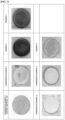
- FIG. 1 is a view showing digital images of the surfaces of electrodes in Examples 1 to 3 and Comparative Examples 1 to 4.
- transition metal hydroxide structures are formed by the binding between copper and nickel ions eluted from the metal substrate due to the elution of copper and nickel substrates by the formation of copper-ammine and nickel-ammine complex ions, and nickel and/or iron ions (derived from a transition metal precursor) contained in the reaction solution.
- Comparative Example 3 and Comparative Example 4 in which the corrosion accelerator is not contained in the reaction solution, have little difference from the commercial copper substrate (Comparative Example 1) and the commercial nickel substrate (Comparative Example 2).
- transition metal hydroxide structure is formed on the metal substrate in Examples 4 to 6 as well.
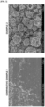
- Comparative Example 1 and Example 2 were observed through a scanning electron microscope (SEM), and the results are shown in FIG. 2 .
- Comparative Example 1 copper substrate
- Example 2 copper substrate
- copper-nickel ammine complex ions copper-nickel ammine complex ions in the electrode of Example 2
- Ni-Fe-Cu hydroxide is grown on the surface of the copper substrate.
- a three-electrode experiment was conducted using an electrode prepared at 25 °C in a 1 M KOH solution as a working electrode, a Hg/HgO electrode as a reference electrode, and a graphite rod as a counter electrode, and oxygen generation reaction performance was evaluated for each prepared electrode.
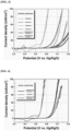
- FIG. 3 is a graph showing results of oxygen generation reactions measured after configuring electrodes including copper substrates as respective working electrodes in Example 1, Example 2, Example 4, Example 5, Comparative Example 1, and Comparative Example 3
- FIG. 4 is a graph showing results of oxygen generation reactions measured after configuring electrodes including nickel substrates as respective working electrodes in Example 3, Comparative Example 2, and Comparative Example 4.
- the efficiency of the oxygen generation reaction is very low in the case of the copper substrate and the nickel substrate, the efficiency of the oxygen generation reaction is significantly increased in the case of Examples 1 to 4 in which the transition metal hydroxide structure is formed by the formation of copper-ammine complex ions and nickel-ammine complex ions on the surface of each of the metal substrates.
- the electrode including the copper substrate it was observed that the electrode (Ni-Fe-Cu) in Example 2 in which a hydroxide structure including three kinds of transition metals is formed has a significant improvement in the efficiency of the oxygen generation reaction as compared with Example 1 because of the formation of hydroxide including multi-component transition metals.
- Comparative Example 3 and Comparative Example 4 in which the corrosion accelerator is not contained in the reaction solution, have performance for the oxygen generation reaction that is almost similar to or slightly improved from Comparative Example 1 (commercial copper substrate) and Comparative Example 2 (commercial nickel substrate), which are the respective references.
- Example 5 and Example 6 that is not shown in the drawings shows similar results to the catalyst performance of Comparative Example 3.
- a large-area hydroxide structure electrode may be prepared by elution and precipitation reactions of the transition metal without a separate power supply, and the electrode may be used as an electrode in the art of the chlor-alkali process and seawater electrolysis.
Landscapes
- Chemical & Material Sciences (AREA)
- Engineering & Computer Science (AREA)
- Chemical Kinetics & Catalysis (AREA)
- Materials Engineering (AREA)
- Metallurgy (AREA)
- Organic Chemistry (AREA)
- Electrochemistry (AREA)
- Inorganic Chemistry (AREA)
- General Chemical & Material Sciences (AREA)
- Mechanical Engineering (AREA)
- Electrodes For Compound Or Non-Metal Manufacture (AREA)
- Catalysts (AREA)
Abstract
Description
- This application claims priority to
Korean Patent Application No. 10-2021-0167005 filed on November 29, 2021 - The present disclosure relates to a method for preparing an electrode including a multi-component transition metal hydroxide structure.
- Fossil fuels such as natural gas, oil, and coal are the most widely used resources, but the reserves are limited, and locally concentrated, and carbon dioxide, nitrogen oxide, sulfur oxide, etc. generated after combustion are known to be the main causes of environmental problems. Hydrogen energy is attracting attention as one of the alternatives to such fossil fuels. When hydrogen is used, a very small amount of nitrogen compounds is discharged as pollutants during combustion, and thus there are few concerns about environmental pollution, and there is an advantage in a recirculation process in which water is generated after combustion. In addition, an attempt to store, in the form of hydrogen, surplus energy produced in connection with new renewable energy such as solar and wind power, which have irregular power generation, using high energy storage capacity characteristics of hydrogen energy, has recently been reported.
- Hydrogen differs from energy storage technology using batteries in that it can convert and store unused amounts of renewable power in large capacity and long-term, and use them later, and has the advantage of energy diversification and scalability.
- Meanwhile, water electrolysis technologies, which are representative hydrogen production technologies, are technologies for directly producing hydrogen from water using electric energy, and high-purity hydrogen can be produced simply and eco-friendly. The water electrolysis technologies may be classified into alkaline electrolysis, solid polymer electrolyte water electrolysis, and high-temperature steam electrolysis.
- Among the water electrolysis technologies, the alkaline electrolysis method is inexpensive and has a high possibility of being commercialized. The alkaline electrolysis method basically is composed of an electrolyte, a separation membrane, and an anode and a cathode which are electrodes, wherein the anode and cathode have the following reaction:
Anode: 4OH- → O2 + 2H2O + 4e-
Cathode: 4H2O + 4e- → 2H2 + 4OH-
- The alkaline electrolysis technology has been commercially verified and is suitable for large-scale hydrogen production and has price competitiveness compared to other technologies, and thus is the most widely used technology in Korea. However, in order to increase the low operating current density and power efficiency, the development on an electrode capable of lowering overvoltage and having durability in hydrogen and oxygen reactions is essential.
- Transition metals such as nickel, iron, copper, cobalt, chromium, and manganese are mainly used as a catalyst material of a water electrolysis electrode in an alkaline environment, and generally high catalyst performance is exhibited when the catalyst material is composed of multi-components such as two or more components rather than a single metal.
- In the related art to the development on an electrode constituting the alkaline electrolysis, a metal, as a plate, having activity in oxygen and hydrogen generation reaction is directly used as an electrode or an electrode is formed by coating a desired substrate with a catalyst by using deposition using atmospheric pressure or high pressure plasma, electrostatic coating, electrochemical plating, hydrothermal synthesis, or the like.
- Since the electrode prepared by the hydrothermal synthesis and the electrostatic coating has a low binding strength between the substrate and the catalyst, a heat treatment at about 1,000 °C is required, and the coating and the heat treatment are repeatedly required, and the electrode prepared by the plasma deposition and the electrochemical plating has an advantage of high binding strength, but a complex continuous process is required. In addition, there is a limitation in that the electrode is rapidly deactivated due to the sintering and agglomeration of metal nanocatalysts during the heat treatment process.
- There is a need for technology of preparing a water electrolysis electrode, the technology being capable of obtaining excellent binding strength with a substrate while having a simple process.
- The present disclosure relates to a method for preparing an electrode which is used in an electrolyzer in which water is split using electric energy to make hydrogen, and more specifically, to a method for preparing a multi-component transition metal hydroxide electrode using the formation of transition metal-ammine complex ions, and to an electrode of a water electrolysis cell which is driven in an alkaline environment using the multi-component transition metal hydroxide electrode.
- In accordance with an aspect of the present invention, a method for preparing an electrode includes the steps of: a) preparing a reaction solution containing a corrosion accelerator and a transition metal precursor including a first transition metal; and b) immersing a metal substrate including a second transition metal in the reaction solution and then reacting the metal substrate while oxygen is injected thereto to form a catalyst layer on the metal substrate.
- In the method for preparing an electrode according to an embodiment of the present invention, the corrosion accelerator may be an inorganic compound including ammonium ions.
- In the method for preparing an electrode according to an embodiment of the present invention, the inorganic compound including ammonium ions may be at least one selected from the group consisting of NH4F, NH4Cl, (NH4)2SO4, (NH4)2CO3, and NH4NO3.
- In the method for preparing an electrode according to an embodiment of the present invention, the catalyst layer formed on the metal substrate may include a second transition metal eluted from the metal substrate by the formation of second transition metal-ammine complex ions.
- In the method for preparing an electrode according to an embodiment of the present invention, the transition metal precursor may include at least one first transition metal selected from the group consisting of vanadium, chromium, manganese, iron, cobalt, nickel, copper, zinc, molybdenum, and tungsten.
- In the method for preparing an electrode according to an embodiment of the present invention, the transition metal precursor may include at least two first transition metals selected from the group consisting of vanadium, chromium, manganese, iron, cobalt, nickel, copper, zinc, molybdenum, and tungsten.
- In the method for preparing an electrode according to an embodiment of the present invention, in step a), a molar ratio of the first transition metal ions:the ammonium ions contained in the reaction solution may be 1:0.1 to 1:1.5.
- In the method for preparing an electrode according to an exemplary embodiment of the present invention, in step b), oxygen may be injected so that the dissolved oxygen amount of the reaction solution is saturated within 20 ppm.
- In the method for preparing an electrode according to an embodiment of the present invention, the reaction in step b) may be performed at 30 °C to 90 °C for 3 hours to 24 hours.
- In the method for preparing an electrode according to an embodiment of the present invention, in step b), oxygen may be injected at a rate of 400 seem to 1500 seem.
- In the method for preparing an electrode according to an embodiment of the present invention, the metal substrate in step b) may include at least one selected from the group consisting of copper, iron, nickel, and cobalt.
- In the method for preparing an electrode according to an embodiment of the present invention, the catalyst layer formed in step b) may include a transition metal hydroxide structure including the first transition metal and the second transition metal.
- In the method for preparing an electrode according to an embodiment of the present invention, the transition metal hydroxide structure included in the catalyst layer may include two or three or more transition metals selected from the group consisting of vanadium, chromium, manganese, iron, cobalt, nickel, copper, zinc, molybdenum, and tungsten.
- In accordance with another aspect of the present invention, there is provided an electrode prepared by the method for preparing an electrode as described above.
- The electrode according to an embodiment of the present invention may be an electrode for a chlor-alkali process or a water electrolysis battery.
- Exemplary embodiments can be understood in more detail from the following description taken in conjunction with the accompanying drawings, in which:
-
FIG. 1 is a view showing digital images of the surfaces of electrodes in Examples 1 to 3 and Comparative Examples 1 to 4; -
FIG. 2 shows scanning electron microscope (SEM) images of the electrodes in Comparative Example 1 and Example 2; -
FIG. 3 is a graph showing results of oxygen generation reactions measured after configuring electrodes including copper substrates as respective working electrodes in Example 1, Example 2, Example 4, Example 5, Comparative Example 1, and Comparative Example 3; and -
FIG. 4 is a graph showing results of oxygen generation reactions measured after configuring electrodes including nickel substrates as respective working electrodes in Example 3, Comparative Example 2, and Comparative Example 4. - Advantages and features of the present invention, and implementation methods thereof will be clarified through following embodiments described in detail with reference to the accompanying drawings. The present invention may, however, be embodied in different forms and should not be construed as limited to the embodiments set forth herein. Rather, these embodiments are provided so that this disclosure will be thorough and complete, and will fully convey the scope of the present invention to those skilled in the art. Further, the present invention is only defined by scopes of claims. Specific descriptions for embodying the present invention will be explained in detail with reference to the accompanying drawings below. Like reference numerals refer to like components regardless of drawings, and the term "and/or" includes any and all combinations of one or more of the associated listed items.
- Unless defined otherwise, all terms (including technical and scientific terms) used herein may be intended to have meanings commonly understood by those skilled in the art. Throughout the specification, when it is described that one part "includes" some components, it is not meant as the exclusion of the other components but to implies the further inclusion of the other components, unless explicitly stated to the contrary. Also, the singular forms, "a," "an," and "the" are intended to include the plural forms as well, unless the context clearly indicates otherwise.
- In the present specification, when a layer, a film, a region, or a plate is referred to as being "above" or "on" another layer, film, region, or plate, it can be not only directly on the layer, film, region, or plate, but intervening layers, films, regions, or plates may also be present.
- In accordance with an aspect of the present invention, there is provided a method for preparing an electrode. The method for preparing an electrode includes the steps of: a) preparing a reaction solution containing a corrosion accelerator and a transition metal precursor including a first transition metal; and b) immersing a metal substrate including a second transition metal in the reaction solution and then reacting the metal substrate while oxygen is injected thereto to form a catalyst layer on the metal substrate.
- The electrode prepared according to an embodiment of the present invention includes a catalyst layer formed on a metal substrate by immersing the metal substrate in a reaction solution containing a transition metal precursor and a corrosion accelerator and then reacting the metal substrate while oxygen is injected thereto, and thus as a substrate, not only a metal favorable for corrosion is used, but a metal resistant to corrosion is also used, and an excellent binding strength between the metal substrate and a catalyst layer formed on the metal substrate may be provided.
- In addition, the electrode according to an embodiment of the present invention is prepared by preparing a reaction solution, immersing a metal substrate in the reaction solution, and then injecting oxygen to form a catalyst layer, and may be prepared to have a large area through a simple process using elution and precipitation reactions of the second transition metal included in the metal substrate without a separate power supply.
- In this case, the large area may be 10 cm2 or more, 30 cm2 or more, 40 cm2 or more, 50 cm2 or more, 60 cm2 or more, 70 cm2 or more, 80 cm2 or more, 90 cm2 or more, 100 cm2 or more, 200 cm2 or more, 300 cm2 or more, 400 cm2 or more, 500 cm2 or more, and may be substantially 5 m2 or less, more substantially 3 m2 or less, but the upper limit value is not limited thereto.
- As an example, the electrode prepared to have a large area according to an embodiment of the present invention may be prepared to have an area level of a commercial water electrolysis electrode. Accordingly, the electrode prepared according to an embodiment of the present invention may be utilized as an electrode in a chlor-alkali process or an electrode in seawater electrolysis technology.
- Hereinafter, the method for preparing an electrode prepared according to an embodiment of the present invention will be described in detail.
- Step a) is to prepare a reaction solution by mixing a transition metal precursor including a first transition metal with a corrosion accelerator in a solvent, and may be mixed by a method known in the art.
- As a specific example, the transition metal precursor may include at least one first transition metal selected from the group consisting of vanadium, chromium, manganese, iron, cobalt, nickel, copper, zinc, molybdenum, and tungsten, preferably at least two first transition metals.
- The above-described first transition metal is a material used as a catalyst of a water electrolysis electrode in an alkaline environment, and may achieve high catalyst performance, and it is generally known that when a structure is composed of multi-components such as two or more components, high catalyst performance is exhibited.
- In an embodiment, the molar concentration of the transition metal precursor may be 0.05 M to 1 M, specifically 0.1 M to 0.8 M, and more specifically 0.1 Mto 0.5 M.
- In an embodiment, the corrosion accelerator included in the reaction solution may be an inorganic compound including ammonium ions.
- The inorganic compound including ammonium ions has strong corrosion properties and thus may effectively corrode the metal substrate, and may play a favorable role in forming a catalyst layer generated on the surface of the metal substrate by using formation reaction of second transition metal-ammine complex ions, which will be described later. This will be described in more detail in the step of forming the catalyst layer, which will be described later.
- For example, the inorganic compound including ammonium ions may be at least one selected from the group consisting of NH4F, NH4Cl, (NH4)2SO4, (NH4)2CO3, and NH4NO3.
- In an embodiment, a molar ratio of the first transition metal ions:the ammonium ions contained in the reaction solution in step a) may be 1:0.05 to 1:1.5, advantageously 1:0.1 to 1:0.9, and more advantageously 1:0.3 to 1:0.7.
- In this case, the number of moles of the first transition metal ions may mean the number of moles of the total ions of the first transition metal contained in the reaction solution.
- In order to form the catalyst layer having excellent catalytic activity in addition to the corrosion effect of the metal substrate, it is preferable that the molar ratio of the first transition metal ions:the ammonium ions contained in the reaction solution satisfies the above-described range.
- In an embodiment, the solvent contained in the reaction solution may dissolve the transition metal precursor to be present in the form of transition metal cations, and for example, may be any one selected from the group consisting of ultrapure water, glycerol, ethylene glycol, polyethylene glycol, diethylene glycol, triethylene glycol, tetraethylene glycol, formamide, N-methylformamide, dimethyl formamide, dimethyl acetylamide, dimethyl sulfoxide, methanol, acetonitrile, 2-pyrrolidinone, acetamide, acrylamide, N-methylurea, urea, and a combination thereof, but is not limited thereto.
- Then, step b), which is performed after the above-described reaction solution is prepared, is for forming a catalyst layer on the metal substrate including the second transition metal through elution and precipitation reactions of the second transition metal, and the metal substrate is immersed in the above-described reaction solution and oxygen is injected thereto.
- In an embodiment, the catalyst layer may include the second transition metal eluted from the metal substrate by the formation of second transition metal-ammine complex ions.
- Specifically, the catalyst layer may be formed by inducing elution of the second transition metal from the surface of the metal substrate with the reaction of forming the second transition metal-ammine complex ions by the corrosion accelerator contained in the reaction solution, and at the same time, by binding the first transition metal ions contained in the reaction solution. In this case, the catalyst layer may be formed by the corrosion reaction that occurs on the surface of the metal substrate by the corrosion accelerator contained in the reaction solution, and by the spontaneous reaction of OH- generated through the injected oxygen with the second transition metal-ammine complex ions.
- Thus, according to an embodiment of the present invention, it is possible to prepare an electrode including a catalyst layer formed on a metal substrate through elution and precipitation reactions of a transition metal without a separate power supply.
- In an embodiment, the oxygen injected into the reaction solution may be injected such that the dissolved oxygen amount of the reaction solution is saturated within 20 ppm, within 10 ppm, or within 5 ppm, and the oxygen may be injected at a rate of 400 seem to 1,500 seem, specifically 600 seem to 1,200 seem, and more specifically 800 seem to 1,000 seem.
- In this case, the injection rate of oxygen injected into the reaction solution may be a value set on the basis of a reactor having a unit volume of 1 L in which the reaction solution is located. For example, when the volume of the reactor increases, the oxygen injection rate may increase by the increased volume ratio of the reactor.
- Meanwhile, a method for injecting oxygen into the solution may be performed by using an oxygen injection device, which is a method known in the art, but the present invention is not limited thereto.
- By adjusting the concentration of the injected oxygen within the above range, the reaction rates of the metal elution reaction (see
Reaction Scheme 1 below) through the formation of transition metal-ammine complex ions and the oxygen reduction reaction (seeReaction Scheme 2 below) on the surface of the metal substrate may be adjusted. In addition, the control of the reaction rate may be a factor that determines the thickness and/or configuration of the catalyst layer formed in the preparation method of the present invention (seeReaction Scheme 3 below).
[Reaction Scheme 1] Elution Reaction Through Formation of Metal-Ammine Complex Ions on Substrate Surface M (second transition metal) + 4NH4 + + O2 → [M(NH3)4]2+ + 2H2O +2e-
[Reaction Scheme 2] Oxygen Reduction Reaction on Substrate Surface O2 +H2O + 2e- → 2OH-
[Reaction Scheme 3] Growth Reaction of Hydroxide Electrode through Binding Metal Ions onto Substrate Surface [M(NH3)4]2+ + 2OH- +4H2O → M(OH)2 + 4NH4 + + 4OH-
- Here, the catalyst layer formed on the metal substrate may include a transition metal hydroxide as seen from
Reaction Scheme 3 above. As described above, after the second transition metal-ammine complex ions formed on the corroded metal substrate induced by the corrosion accelerator contained in the reaction solution is deposited, the transition metal hydroxide is formed and grown through a spontaneous reaction with OH- generated through the injected oxygen to form a catalyst layer. In this case, the catalyst layer may be formed by growing due to the binding of the first transition metal contained in the reaction solution. - Here, the corroded surface of the metal substrate induced from the corrosion accelerator, which is an inorganic compound including ammonium ions, is formed by growing on the metal substrate in the form of being bound with the second transition metal-ammine complex ions that are eluted from the metal substrate, and thus the present invention may have an excellent binding strength to the transition metal hydroxide including the first transition metal and the second transition metal.
- In an embodiment, the metal substrate including the second transition metal may include one or more selected from the group consisting of copper, iron, nickel, and cobalt.
- For example, the metal substrate may be an alloy including at least one among the above-described transition metals, and a non-limiting example thereof may be stainless steel, but is not limited thereto.
- In the present invention, the elution of the second transition metal is induced on the surface of the metal substrate, and at the same time, the binding of the first transition metal ions in the reaction solution is promoted, such that the catalyst layer including a multi-component transition metal hydroxide including at least two, preferably at least three kinds of transition metals may be grown.
- In an embodiment, the catalyst layer may be formed by reacting a reaction solution, in which a metal substrate is immersed under the injection of oxygen in the conditions as described above, at 30 °C to 90 °C for 3 hours to 24 hours.
- As a specific example, the reaction for forming the catalyst layer may be performed at 40 °C to 80 °C, advantageously 50 °C to 70 °C, for 5 hours to 20 hours, preferably 5 hours to 15 hours, and more preferably 5 hours to 10 hours.
- When the temperature is less than 30 °C in the reaction conditions for forming the catalyst layer, the corrosion of the metal substrate and the growth of the transition metal hydroxide may not be smoothly performed, and thus the process efficiency may be deteriorated, and when the temperature is greater than 90 °C, the first transition metal ions contained in the reaction solution may be precipitated as a transition metal hydroxide salt in the reaction solution rather than on the surface of the metal substrate.
- In addition, when the reaction time is less than 3 hours, the efficiency of forming the catalyst layer may be deteriorated, and when the reaction time is more than 24 hours, the corrosion of the metal substrate may be accelerated to reduce the catalytic activity of the finally prepared electrode even though the catalyst layer is formed.
- Accordingly, in order to form the catalyst layer by the efficient corrosion of a metal substrate and the growth of a transition metal hydroxide, and finally prepare an electrode having excellent catalytic activity, a reaction for forming the catalyst layer is preferably performed under the above-described temperature and time conditions.
- As described above, the catalyst layer formed on the metal substrate may include a hydroxide structure of a transition metal including the first transition metal and the second transition metal, and specifically, the transition metal hydroxide structure may include two or three or more transition metals selected from the group consisting of vanadium, chromium, manganese, iron, cobalt, nickel, copper, zinc, molybdenum, and tungsten. The present invention has a simple process, may prepare a catalyst composed of multi-components, and at the same time, may prepare an electrode having excellent binding strength to a substrate.
- Another embodiment of the present invention provides an electrode prepared by the above-described preparation method, and the electrode may include a metal substrate and a catalyst layer disposed on the metal substrate and including a transition metal hydroxide structure.
- The catalyst layer including the transition metal hydroxide structure may include a layered double hydroxide (LDH) structure having a two-dimensional structure. Here, LDH refers to a hydroxide having a two-dimensional layered structure in which divalent metal cations are surrounded by six OH- in an octahedral form, and some of the divalent metal cations are substituted by trivalent metal cations, and thus the surface of the divalent metal cation has a positive charge, and the positive charge on the surface of the layered double hydroxide structure may be offset by anions present between the layered structures.
- The layered double hydroxide structure allows easy anion exchange as compared with other exchangers and may be applied to various fields such as catalysts, adsorbents, flame retardants, and photocatalysts due to thermal stability, electrical and optical properties, and the like.
- Here, the layered double hydroxide structure may be present in a state chemically bonded on the surface of the metal substrate. Characteristics of easy material transfer and ion conduction of the layered double hydroxide structure may allow the water electrolysis stack to be operated with high efficiency and high current, and the durability may be improved according to a voltage potential change when a water electrolysis system is repeatedly operated at on/off in an alkaline solution. Accordingly, the water electrolysis cell, to which the electrode is applied, may secure stability with respect to repeated on/off operation, thereby enabling connection with intermittent renewable energy such as solar or wind power.
- In an embodiment, the thickness of the catalyst layer may be 50 nm to 50 µm, specifically 100 nm to 20 µm, and more specifically 200 nm to 10 µm.
- The electrode of the present invention may be used as an electrode for a chlor-alkali process or a water electrolysis battery, but the present invention is not limited thereto.
- Another embodiment of the present invention provides an alkaline electrolysis cell containing the electrode prepared by the preparation method.
- In the present specification, the term "alkaline electrolysis is a kind of water electrolysis method, and may mean a technology of using an alkaline aqueous solution as an electrolyte and using a separate separation membrane for the separation of hydrogen/oxygen. Specifically, in the alkaline electrolysis method, an ion separation membrane and an electrolyte are injected between the cathode and the anode, which are electrodes, and a constant voltage and a constant current flow through both electrodes, thereby producing hydrogen.
- The cathode and the anode generate hydrogen gas and oxygen gas, respectively, according to the following
Reaction Scheme 4, and the generated hydrogen gas and oxygen gas may be discharged to the outside.
[Reaction Scheme 4] Anode: 4OH- → O2 + 2H2O + 4e-Cathode: 4H2O + 4e- → 2H2 + 4OH-
- Specifically, the OH- ions generated at the cathode may pass through the separation membrane and move to the anode, and may be oxidized at the anode to generate water and oxygen gas.
- In an embodiment of the present invention, the electrolyte is composed of an alkaline aqueous solution, and the alkaline aqueous solution may mean an aqueous solution exhibiting basicity. In this case, the alkaline aqueous solution may include a hydroxide of an alkaline metal element or an alkaline earth metal element. For example, the hydroxide of the alkaline metal may include at least one hydroxide selected from the group consisting of LiOH, NaOH, KOH, RbOH, and CsOH.
- The ion separation membrane may be disposed inside the electrolyte to selectively allow specific ions in the electrolyte to pass therethrough. In this case, the ion separation membrane may selectively allow cations or anions to pass therethrough according to a shape of the ionized group attached to a membrane matrix. For example, when the ion separation membrane has anion groups such as-SO3-, -COO-, -PO3 2-, -PO3H-, and -C6H4O- in a membrane backbone, only cations may be selectively passed therethrough. For example, when the ion separation membrane has cation groups such as -NH3+, -NRH2+, -NR2H+, -NR3+, -PR3+, and - SR2+ on a membrane backbone, only anions may be selectively passed therethrough.
- Hereinafter, preferred Examples of the present invention and Comparative Examples will be described. However, the following Examples are merely preferred examples of the present invention, but the present invention is not limited by the following Examples.
- A reaction solution was prepared by mixing 0.37M Ni(SO4)2 as a transition metal precursor and 0.2M NH4F as a corrosion accelerator in deionized water.
- A copper substrate was immersed in the prepared reaction solution, the copper substrate was then reacted at 70 °C for 7 hours with a stirring rate maintained at 150 rpm while oxygen is injected at a rate of 900 seem using an oxygen injection device to form a catalyst layer including a Ni-Cu hydroxide structure on the copper substrate, thereby preparing an electrode.
- Example 2 was performed in the same manner as in Example 1 except that 0.12M Fe(NO3)3 was added to the reaction solution and 0.25M NH4F was mixed as a corrosion accelerator, and a catalyst layer including a Ni-Fe-Cu hydroxide structure was formed on a copper substrate, thereby preparing an electrode.
- A reaction solution was prepared by mixing 0.185M Fe(NO3)3 as a transition metal precursor and 0.093M NH4F as a corrosion accelerator in deionized water.
- A nickel substrate was immersed in the prepared reaction solution, the copper substrate was then reacted at 50 °C for 7 hours with a stirring rate maintained at 150 rpm while oxygen is injected at a rate of 900 seem using an oxygen injection device to form a catalyst layer including an Fe-Ni hydroxide structure on the nickel substrate, thereby preparing an electrode.
- Example 4 was performed in the same manner as in Example 2 except that 0.5M NH4F as a corrosion accelerator was mixed with the reaction solution.
- Example 5 was performed in the same manner as in Example 2 except that the reaction was performed for 24 hours in the process of forming a catalyst layer.
- Example 6 was performed in the same manner as in Example 2 except that the reaction was performed in the reaction temperature condition of 90 °C in the process of forming a catalyst layer.
- A commercial copper substrate in which a catalyst layer is not formed was used as an electrode.
- A commercial nickel substrate in which a catalyst layer is not formed was used as an electrode.
- Comparative Example 3 was performed in the same manner as in Example 1 except that a corrosion accelerator was not contained in the reaction solution.
- Comparative Example 4 was performed in the same manner as in Example 3 except that a corrosion accelerator was not contained in the reaction solution.
- The surface of each prepared electrode was observed to evaluate whether a hydroxide structure was formed.
-
FIG. 1 is a view showing digital images of the surfaces of electrodes in Examples 1 to 3 and Comparative Examples 1 to 4. - Referring to
FIG. 1 , it is observed that on the electrodes of Examples 1 to 3, in which ammonium ions (corrosion accelerator) are contained in the reaction solution, transition metal hydroxide structures are formed by the binding between copper and nickel ions eluted from the metal substrate due to the elution of copper and nickel substrates by the formation of copper-ammine and nickel-ammine complex ions, and nickel and/or iron ions (derived from a transition metal precursor) contained in the reaction solution. - On the other hand, it may be seen that Comparative Example 3 and Comparative Example 4, in which the corrosion accelerator is not contained in the reaction solution, have little difference from the commercial copper substrate (Comparative Example 1) and the commercial nickel substrate (Comparative Example 2).
- Although not shown in the drawings, it is confirmed that the transition metal hydroxide structure is formed on the metal substrate in Examples 4 to 6 as well.
- Additionally, the electrodes in Comparative Example 1 and Example 2 were observed through a scanning electron microscope (SEM), and the results are shown in
FIG. 2 . - Referring to the SEM image of
FIG. 2 , when Comparative Example 1 (copper substrate) is compared with Example 2, it may be confirmed that copper is eluted from the copper substrate by the formation of copper-nickel ammine complex ions in the electrode of Example 2, and thus a Ni-Fe-Cu hydroxide is grown on the surface of the copper substrate. - A three-electrode experiment was conducted using an electrode prepared at 25 °C in a 1 M KOH solution as a working electrode, a Hg/HgO electrode as a reference electrode, and a graphite rod as a counter electrode, and oxygen generation reaction performance was evaluated for each prepared electrode.
-
FIG. 3 is a graph showing results of oxygen generation reactions measured after configuring electrodes including copper substrates as respective working electrodes in Example 1, Example 2, Example 4, Example 5, Comparative Example 1, and Comparative Example 3, andFIG. 4 is a graph showing results of oxygen generation reactions measured after configuring electrodes including nickel substrates as respective working electrodes in Example 3, Comparative Example 2, and Comparative Example 4. - Referring to
FIGS. 3 and 4 , it may be confirmed that although the efficiency of the oxygen generation reaction is very low in the case of the copper substrate and the nickel substrate, the efficiency of the oxygen generation reaction is significantly increased in the case of Examples 1 to 4 in which the transition metal hydroxide structure is formed by the formation of copper-ammine complex ions and nickel-ammine complex ions on the surface of each of the metal substrates. - In particular, in the case of the electrode including the copper substrate, it was observed that the electrode (Ni-Fe-Cu) in Example 2 in which a hydroxide structure including three kinds of transition metals is formed has a significant improvement in the efficiency of the oxygen generation reaction as compared with Example 1 because of the formation of hydroxide including multi-component transition metals.
- On the other hand, it may be seen that Comparative Example 3 and Comparative Example 4, in which the corrosion accelerator is not contained in the reaction solution, have performance for the oxygen generation reaction that is almost similar to or slightly improved from Comparative Example 1 (commercial copper substrate) and Comparative Example 2 (commercial nickel substrate), which are the respective references.
- In addition, it is confirmed that Example 5 and Example 6 that is not shown in the drawings shows similar results to the catalyst performance of Comparative Example 3.
- According to the present invention, excellent oxygen generation reaction efficiency may be secured, a large-area hydroxide structure electrode may be prepared by elution and precipitation reactions of the transition metal without a separate power supply, and the electrode may be used as an electrode in the art of the chlor-alkali process and seawater electrolysis.
- In addition, when the electrode of the present invention is used, hydrogen production costs using water electrolysis may be reduced with high oxygen generation reaction efficiency.
- Although the embodiments of the present invention have been described, the present invention is not limited to the above-described embodiments, and is variously prepared. It will be understood by those skilled in the art to which the present invention pertains that the present invention can be carried out in other specific forms without changing the technical spirit or essential features. Therefore, the above-described embodiments are to be understood in all aspects as illustrative and not restrictive.
Claims (15)
- A method for preparing an electrode comprising the steps of:a) preparing a reaction solution containing a corrosion accelerator and a transition metal precursor including a first transition metal; andb) immersing a metal substrate including a second transition metal in the reaction solution and then reacting the metal substrate while oxygen is injected thereto to form a catalyst layer on the metal substrate.
- The method of claim 1, wherein the corrosion accelerator is an inorganic compound including ammonium ions.
- The method of claim 2, wherein the inorganic compound is at least one selected from the group consisting of NH4F, NH4Cl, (NH4)2SO4, (NH4)2CO3 and NH4NO3.
- The method of claim 2, wherein the catalyst layer comprises the second transition metal eluted from the metal substrate by the formation of second transition metal-ammine complex ions.
- The method of claim 1, wherein the transition metal precursor comprises at least one first transition metal selected from the group consisting of vanadium, chromium, manganese, iron, cobalt, nickel, copper, zinc, molybdenum, and tungsten.
- The method of claim 1, wherein the transition metal precursor comprises at least two first transition metals selected from the group consisting of vanadium, chromium, manganese, iron, cobalt, nickel, copper, zinc, molybdenum, and tungsten.
- The method of claim 2, wherein, in step a) above, a molar ratio of the first transition metal ions:the ammonium ions contained in the reaction solution is 1:0.1 to 1:1.5.
- The method of claim 1, wherein, in step b) above, oxygen is injected so that the dissolved oxygen amount of the reaction solution is saturated within 20 ppm.
- The method of claim 1, wherein the reaction in step b) above is performed at 30 °C to 90 °C for 3 hours to 24 hours.
- The method of claim 1, wherein, in step b) above, oxygen is injected at a rate of 400 seem to 1500 seem.
- The method of claim 1, wherein the metal substrate in step b) above comprises at least one selected from the group consisting of copper, iron, nickel, and cobalt.
- The method of claim 1, wherein the catalyst layer in step b) above comprises a transition metal hydroxide structure including the first transition metal and the second transition metal.
- The method of claim 12, wherein the transition metal hydroxide structure comprises two or three or more transition metals selected from the group consisting of vanadium, chromium, manganese, iron, cobalt, nickel, copper, zinc, molybdenum, and tungsten.
- An electrode prepared by the preparation method in any of claims 1 to 13.
- The electrode of claim 14, wherein the electrode is for a chlor-alkali process or a water electrolysis battery.
Applications Claiming Priority (1)
| Application Number | Priority Date | Filing Date | Title |
|---|---|---|---|
| KR1020210167005A KR102680176B1 (en) | 2021-11-29 | 2021-11-29 | Method for preparing an electrode including a multi-component transition metal hydroxide structure and Electrode fabricated Therefrom |
Publications (2)
| Publication Number | Publication Date |
|---|---|
| EP4215645A1 true EP4215645A1 (en) | 2023-07-26 |
| EP4215645B1 EP4215645B1 (en) | 2025-01-29 |
Family
ID=84044185
Family Applications (1)
| Application Number | Title | Priority Date | Filing Date |
|---|---|---|---|
| EP22204192.3A Active EP4215645B1 (en) | 2021-11-29 | 2022-10-27 | Method for preparing an electrode including a multicomponent transition metal hydroxide structure |
Country Status (2)
| Country | Link |
|---|---|
| EP (1) | EP4215645B1 (en) |
| KR (1) | KR102680176B1 (en) |
Families Citing this family (1)
| Publication number | Priority date | Publication date | Assignee | Title |
|---|---|---|---|---|
| KR102918631B1 (en) * | 2023-07-27 | 2026-01-27 | 포항공과대학교 산학협력단 | Layered double hydroxide electrode catalyst for electrolysis of water and method of manufacturing same |
Citations (2)
| Publication number | Priority date | Publication date | Assignee | Title |
|---|---|---|---|---|
| CN109161920A (en) * | 2018-09-29 | 2019-01-08 | 陕西科技大学 | A kind of preparation method of foam copper self-supporting nickel zinc double-metal hydroxide catalyst |
| KR20210091891A (en) * | 2020-01-15 | 2021-07-23 | 한국에너지기술연구원 | Method for manufacturing electrode having a catalyst layer including layered double hydroxide(LDH) |
Family Cites Families (2)
| Publication number | Priority date | Publication date | Assignee | Title |
|---|---|---|---|---|
| AU2019373092B2 (en) * | 2018-10-29 | 2025-08-28 | Kohodo Hydrogen Energy Pty Ltd | Hydrogen evolution reaction catalyst |
| KR102210525B1 (en) * | 2019-04-12 | 2021-02-02 | 재단법인대구경북과학기술원 | Electrode for Oxygen Evolution Reaction and The Fabrication Method Thereof |
-
2021
- 2021-11-29 KR KR1020210167005A patent/KR102680176B1/en active Active
-
2022
- 2022-10-27 EP EP22204192.3A patent/EP4215645B1/en active Active
Patent Citations (2)
| Publication number | Priority date | Publication date | Assignee | Title |
|---|---|---|---|---|
| CN109161920A (en) * | 2018-09-29 | 2019-01-08 | 陕西科技大学 | A kind of preparation method of foam copper self-supporting nickel zinc double-metal hydroxide catalyst |
| KR20210091891A (en) * | 2020-01-15 | 2021-07-23 | 한국에너지기술연구원 | Method for manufacturing electrode having a catalyst layer including layered double hydroxide(LDH) |
Also Published As
| Publication number | Publication date |
|---|---|
| KR20230079843A (en) | 2023-06-07 |
| EP4215645B1 (en) | 2025-01-29 |
| KR102680176B1 (en) | 2024-07-01 |
Similar Documents
| Publication | Publication Date | Title |
|---|---|---|
| Shuai et al. | Recent developments of MXene-based catalysts for hydrogen production by water splitting | |
| Gonçalves et al. | Recent advances in ternary layered double hydroxide electrocatalysts for the oxygen evolution reaction | |
| Zhang et al. | Hydrolysis assisted in-situ growth of 3D hierarchical FeS/NiS/nickel foam electrode for overall water splitting | |
| Rathore et al. | Aggregates of Ni/Ni (OH) 2/NiOOH nanoworms on carbon cloth for electrocatalytic hydrogen evolution | |
| Zhao et al. | Transition metal–phosphorus-based materials for electrocatalytic energy conversion reactions | |
| Wang et al. | Amorphous–crystalline FeNi 2 S 4@ NiFe–LDH nanograsses with molten salt as an industrially promising electrocatalyst for oxygen evolution | |
| JP2023522183A (en) | Manufacturing method for electrocatalyst electrode | |
| CN115697553A (en) | Anion-exchange membrane electrolyzer with platinum-group metal-free self-supporting oxygen evolution electrode | |
| KR20210091891A (en) | Method for manufacturing electrode having a catalyst layer including layered double hydroxide(LDH) | |
| Perović et al. | Advances in nickel‐based catalysts for alkaline water electrolysis: comprehensive review of current research direction for HER and OER applications | |
| KR102586625B1 (en) | Anode for alkaline water electrolysis and method for manufacturing the same | |
| US20240392453A1 (en) | Nano flake-shaped spinel oxidation catalyst for anion exchange membrane water electrolysis and preparation method thereof | |
| US20240426002A1 (en) | Nanostructured electrodes | |
| CN115161691A (en) | Oxygen evolution catalyst of FeCoNiMg high-entropy amorphous alloy powder and preparation method thereof | |
| Yang et al. | Facile synthesis of N and P Co-doped NiMoO4 hollow nanowires and electrochemical deposition of NiFe-layered double hydroxide for boosting overall seawater splitting | |
| Wu et al. | Recent progress in polyaniline-based catalysts for electrochemical energy conversion | |
| EP4215645B1 (en) | Method for preparing an electrode including a multicomponent transition metal hydroxide structure | |
| CN118147696A (en) | Layered double hydroxide hollow nano cage catalyst and preparation method and application thereof | |
| Liu et al. | Recent development of non-noble metal catalysts for the oxygen evolution reaction (OER) under different pH | |
| JP2026002777A (en) | Electrochemical catalyst composite and method for preparing same | |
| Zou et al. | Ethanol combustion-assisted fast synthesis of tri-metal oxides with reduced graphene oxide for superior overall water splitting performance | |
| Wang et al. | Development of high-performance cobalt oxide electrocatalysts for alkaline water splitting via integrated pulsed laser ablation in liquid (PLAL) and electrophoretic deposition (EPD) | |
| RU2835975C1 (en) | Method of making electrode for electrocatalysis | |
| US20250297386A1 (en) | Method of producing electrocatalyst coated electrode by electrochemical oxidation | |
| CN118581514B (en) | Sulfur ion oxidation electrode and preparation method and application thereof |
Legal Events
| Date | Code | Title | Description |
|---|---|---|---|
| PUAI | Public reference made under article 153(3) epc to a published international application that has entered the european phase |
Free format text: ORIGINAL CODE: 0009012 |
|
| STAA | Information on the status of an ep patent application or granted ep patent |
Free format text: STATUS: REQUEST FOR EXAMINATION WAS MADE |
|
| 17P | Request for examination filed |
Effective date: 20221027 |
|
| AK | Designated contracting states |
Kind code of ref document: A1 Designated state(s): AL AT BE BG CH CY CZ DE DK EE ES FI FR GB GR HR HU IE IS IT LI LT LU LV MC ME MK MT NL NO PL PT RO RS SE SI SK SM TR |
|
| P01 | Opt-out of the competence of the unified patent court (upc) registered |
Effective date: 20230731 |
|
| GRAP | Despatch of communication of intention to grant a patent |
Free format text: ORIGINAL CODE: EPIDOSNIGR1 |
|
| STAA | Information on the status of an ep patent application or granted ep patent |
Free format text: STATUS: GRANT OF PATENT IS INTENDED |
|
| RIC1 | Information provided on ipc code assigned before grant |
Ipc: C23C 22/73 20060101ALI20240205BHEP Ipc: C23C 22/34 20060101ALI20240205BHEP Ipc: C25B 11/075 20210101ALI20240205BHEP Ipc: C25B 11/061 20210101ALI20240205BHEP Ipc: C25B 11/052 20210101ALI20240205BHEP Ipc: C25B 1/46 20060101ALI20240205BHEP Ipc: C25B 1/04 20210101AFI20240205BHEP |
|
| INTG | Intention to grant announced |
Effective date: 20240220 |
|
| GRAJ | Information related to disapproval of communication of intention to grant by the applicant or resumption of examination proceedings by the epo deleted |
Free format text: ORIGINAL CODE: EPIDOSDIGR1 |
|
| STAA | Information on the status of an ep patent application or granted ep patent |
Free format text: STATUS: REQUEST FOR EXAMINATION WAS MADE |
|
| GRAP | Despatch of communication of intention to grant a patent |
Free format text: ORIGINAL CODE: EPIDOSNIGR1 |
|
| STAA | Information on the status of an ep patent application or granted ep patent |
Free format text: STATUS: GRANT OF PATENT IS INTENDED |
|
| INTC | Intention to grant announced (deleted) | ||
| INTG | Intention to grant announced |
Effective date: 20240619 |
|
| GRAS | Grant fee paid |
Free format text: ORIGINAL CODE: EPIDOSNIGR3 |
|
| GRAA | (expected) grant |
Free format text: ORIGINAL CODE: 0009210 |
|
| STAA | Information on the status of an ep patent application or granted ep patent |
Free format text: STATUS: THE PATENT HAS BEEN GRANTED |
|
| AK | Designated contracting states |
Kind code of ref document: B1 Designated state(s): AL AT BE BG CH CY CZ DE DK EE ES FI FR GB GR HR HU IE IS IT LI LT LU LV MC ME MK MT NL NO PL PT RO RS SE SI SK SM TR |
|
| REG | Reference to a national code |
Ref country code: GB Ref legal event code: FG4D |
|
| REG | Reference to a national code |
Ref country code: CH Ref legal event code: EP |
|
| REG | Reference to a national code |
Ref country code: DE Ref legal event code: R096 Ref document number: 602022010053 Country of ref document: DE |
|
| REG | Reference to a national code |
Ref country code: IE Ref legal event code: FG4D |
|
| REG | Reference to a national code |
Ref country code: NL Ref legal event code: MP Effective date: 20250129 |
|
| PG25 | Lapsed in a contracting state [announced via postgrant information from national office to epo] |
Ref country code: NL Free format text: LAPSE BECAUSE OF FAILURE TO SUBMIT A TRANSLATION OF THE DESCRIPTION OR TO PAY THE FEE WITHIN THE PRESCRIBED TIME-LIMIT Effective date: 20250129 |
|
| PG25 | Lapsed in a contracting state [announced via postgrant information from national office to epo] |
Ref country code: RS Free format text: LAPSE BECAUSE OF FAILURE TO SUBMIT A TRANSLATION OF THE DESCRIPTION OR TO PAY THE FEE WITHIN THE PRESCRIBED TIME-LIMIT Effective date: 20250429 |
|
| PG25 | Lapsed in a contracting state [announced via postgrant information from national office to epo] |
Ref country code: FI Free format text: LAPSE BECAUSE OF FAILURE TO SUBMIT A TRANSLATION OF THE DESCRIPTION OR TO PAY THE FEE WITHIN THE PRESCRIBED TIME-LIMIT Effective date: 20250129 |
|
| PG25 | Lapsed in a contracting state [announced via postgrant information from national office to epo] |
Ref country code: PL Free format text: LAPSE BECAUSE OF FAILURE TO SUBMIT A TRANSLATION OF THE DESCRIPTION OR TO PAY THE FEE WITHIN THE PRESCRIBED TIME-LIMIT Effective date: 20250129 |
|
| PG25 | Lapsed in a contracting state [announced via postgrant information from national office to epo] |
Ref country code: ES Free format text: LAPSE BECAUSE OF FAILURE TO SUBMIT A TRANSLATION OF THE DESCRIPTION OR TO PAY THE FEE WITHIN THE PRESCRIBED TIME-LIMIT Effective date: 20250129 |
|
| REG | Reference to a national code |
Ref country code: LT Ref legal event code: MG9D |
|
| PG25 | Lapsed in a contracting state [announced via postgrant information from national office to epo] |
Ref country code: NO Free format text: LAPSE BECAUSE OF FAILURE TO SUBMIT A TRANSLATION OF THE DESCRIPTION OR TO PAY THE FEE WITHIN THE PRESCRIBED TIME-LIMIT Effective date: 20250429 Ref country code: IS Free format text: LAPSE BECAUSE OF FAILURE TO SUBMIT A TRANSLATION OF THE DESCRIPTION OR TO PAY THE FEE WITHIN THE PRESCRIBED TIME-LIMIT Effective date: 20250529 |
|
| REG | Reference to a national code |
Ref country code: AT Ref legal event code: MK05 Ref document number: 1763501 Country of ref document: AT Kind code of ref document: T Effective date: 20250129 |
|
| PG25 | Lapsed in a contracting state [announced via postgrant information from national office to epo] |
Ref country code: HR Free format text: LAPSE BECAUSE OF FAILURE TO SUBMIT A TRANSLATION OF THE DESCRIPTION OR TO PAY THE FEE WITHIN THE PRESCRIBED TIME-LIMIT Effective date: 20250129 |
|
| PG25 | Lapsed in a contracting state [announced via postgrant information from national office to epo] |
Ref country code: LV Free format text: LAPSE BECAUSE OF FAILURE TO SUBMIT A TRANSLATION OF THE DESCRIPTION OR TO PAY THE FEE WITHIN THE PRESCRIBED TIME-LIMIT Effective date: 20250129 Ref country code: PT Free format text: LAPSE BECAUSE OF FAILURE TO SUBMIT A TRANSLATION OF THE DESCRIPTION OR TO PAY THE FEE WITHIN THE PRESCRIBED TIME-LIMIT Effective date: 20250529 |
|
| PG25 | Lapsed in a contracting state [announced via postgrant information from national office to epo] |
Ref country code: GR Free format text: LAPSE BECAUSE OF FAILURE TO SUBMIT A TRANSLATION OF THE DESCRIPTION OR TO PAY THE FEE WITHIN THE PRESCRIBED TIME-LIMIT Effective date: 20250430 Ref country code: BG Free format text: LAPSE BECAUSE OF FAILURE TO SUBMIT A TRANSLATION OF THE DESCRIPTION OR TO PAY THE FEE WITHIN THE PRESCRIBED TIME-LIMIT Effective date: 20250129 |
|
| PG25 | Lapsed in a contracting state [announced via postgrant information from national office to epo] |
Ref country code: AT Free format text: LAPSE BECAUSE OF FAILURE TO SUBMIT A TRANSLATION OF THE DESCRIPTION OR TO PAY THE FEE WITHIN THE PRESCRIBED TIME-LIMIT Effective date: 20250129 |
|
| PG25 | Lapsed in a contracting state [announced via postgrant information from national office to epo] |
Ref country code: SE Free format text: LAPSE BECAUSE OF FAILURE TO SUBMIT A TRANSLATION OF THE DESCRIPTION OR TO PAY THE FEE WITHIN THE PRESCRIBED TIME-LIMIT Effective date: 20250129 |
|
| PG25 | Lapsed in a contracting state [announced via postgrant information from national office to epo] |
Ref country code: SM Free format text: LAPSE BECAUSE OF FAILURE TO SUBMIT A TRANSLATION OF THE DESCRIPTION OR TO PAY THE FEE WITHIN THE PRESCRIBED TIME-LIMIT Effective date: 20250129 |
|
| PG25 | Lapsed in a contracting state [announced via postgrant information from national office to epo] |
Ref country code: DK Free format text: LAPSE BECAUSE OF FAILURE TO SUBMIT A TRANSLATION OF THE DESCRIPTION OR TO PAY THE FEE WITHIN THE PRESCRIBED TIME-LIMIT Effective date: 20250129 |
|
| PG25 | Lapsed in a contracting state [announced via postgrant information from national office to epo] |
Ref country code: IT Free format text: LAPSE BECAUSE OF FAILURE TO SUBMIT A TRANSLATION OF THE DESCRIPTION OR TO PAY THE FEE WITHIN THE PRESCRIBED TIME-LIMIT Effective date: 20250129 |
|
| PGFP | Annual fee paid to national office [announced via postgrant information from national office to epo] |
Ref country code: FR Payment date: 20250908 Year of fee payment: 4 |
|
| PG25 | Lapsed in a contracting state [announced via postgrant information from national office to epo] |
Ref country code: CZ Free format text: LAPSE BECAUSE OF FAILURE TO SUBMIT A TRANSLATION OF THE DESCRIPTION OR TO PAY THE FEE WITHIN THE PRESCRIBED TIME-LIMIT Effective date: 20250129 Ref country code: EE Free format text: LAPSE BECAUSE OF FAILURE TO SUBMIT A TRANSLATION OF THE DESCRIPTION OR TO PAY THE FEE WITHIN THE PRESCRIBED TIME-LIMIT Effective date: 20250129 |
|
| PG25 | Lapsed in a contracting state [announced via postgrant information from national office to epo] |
Ref country code: RO Free format text: LAPSE BECAUSE OF FAILURE TO SUBMIT A TRANSLATION OF THE DESCRIPTION OR TO PAY THE FEE WITHIN THE PRESCRIBED TIME-LIMIT Effective date: 20250129 |
|
| PG25 | Lapsed in a contracting state [announced via postgrant information from national office to epo] |
Ref country code: SK Free format text: LAPSE BECAUSE OF FAILURE TO SUBMIT A TRANSLATION OF THE DESCRIPTION OR TO PAY THE FEE WITHIN THE PRESCRIBED TIME-LIMIT Effective date: 20250129 |
|
| REG | Reference to a national code |
Ref country code: DE Ref legal event code: R097 Ref document number: 602022010053 Country of ref document: DE |
|
| PLBE | No opposition filed within time limit |
Free format text: ORIGINAL CODE: 0009261 |
|
| STAA | Information on the status of an ep patent application or granted ep patent |
Free format text: STATUS: NO OPPOSITION FILED WITHIN TIME LIMIT |
|
| 26N | No opposition filed |
Effective date: 20251030 |
|
| PGFP | Annual fee paid to national office [announced via postgrant information from national office to epo] |
Ref country code: DE Payment date: 20250902 Year of fee payment: 4 |