EP4215468A1 - Yarn winder - Google Patents
Yarn winder Download PDFInfo
- Publication number
- EP4215468A1 EP4215468A1 EP23151538.8A EP23151538A EP4215468A1 EP 4215468 A1 EP4215468 A1 EP 4215468A1 EP 23151538 A EP23151538 A EP 23151538A EP 4215468 A1 EP4215468 A1 EP 4215468A1
- Authority
- EP
- European Patent Office
- Prior art keywords
- yarn
- storage
- section
- light
- storage roller
- Prior art date
- Legal status (The legal status is an assumption and is not a legal conclusion. Google has not performed a legal analysis and makes no representation as to the accuracy of the status listed.)
- Granted
Links
Images






Classifications
-
- B—PERFORMING OPERATIONS; TRANSPORTING
- B65—CONVEYING; PACKING; STORING; HANDLING THIN OR FILAMENTARY MATERIAL
- B65H—HANDLING THIN OR FILAMENTARY MATERIAL, e.g. SHEETS, WEBS, CABLES
- B65H51/00—Forwarding filamentary material
- B65H51/20—Devices for temporarily storing filamentary material during forwarding, e.g. for buffer storage
- B65H51/22—Reels or cages, e.g. cylindrical, with storing and forwarding surfaces provided by rollers or bars
-
- B—PERFORMING OPERATIONS; TRANSPORTING
- B65—CONVEYING; PACKING; STORING; HANDLING THIN OR FILAMENTARY MATERIAL
- B65H—HANDLING THIN OR FILAMENTARY MATERIAL, e.g. SHEETS, WEBS, CABLES
- B65H54/00—Winding, coiling, or depositing filamentary material
- B65H54/02—Winding and traversing material on to reels, bobbins, tubes, or like package cores or formers
- B65H54/40—Arrangements for rotating packages
- B65H54/54—Arrangements for supporting cores or formers at winding stations; Securing cores or formers to driving members
- B65H54/553—Both-ends supporting arrangements
-
- B—PERFORMING OPERATIONS; TRANSPORTING
- B65—CONVEYING; PACKING; STORING; HANDLING THIN OR FILAMENTARY MATERIAL
- B65H—HANDLING THIN OR FILAMENTARY MATERIAL, e.g. SHEETS, WEBS, CABLES
- B65H54/00—Winding, coiling, or depositing filamentary material
- B65H54/02—Winding and traversing material on to reels, bobbins, tubes, or like package cores or formers
- B65H54/40—Arrangements for rotating packages
- B65H54/44—Arrangements for rotating packages in which the package, core, or former is engaged with, or secured to, a driven member rotatable about the axis of the package
-
- B—PERFORMING OPERATIONS; TRANSPORTING
- B65—CONVEYING; PACKING; STORING; HANDLING THIN OR FILAMENTARY MATERIAL
- B65H—HANDLING THIN OR FILAMENTARY MATERIAL, e.g. SHEETS, WEBS, CABLES
- B65H54/00—Winding, coiling, or depositing filamentary material
- B65H54/70—Other constructional features of yarn-winding machines
-
- B—PERFORMING OPERATIONS; TRANSPORTING
- B65—CONVEYING; PACKING; STORING; HANDLING THIN OR FILAMENTARY MATERIAL
- B65H—HANDLING THIN OR FILAMENTARY MATERIAL, e.g. SHEETS, WEBS, CABLES
- B65H63/00—Warning or safety devices, e.g. automatic fault detectors, stop-motions ; Quality control of the package
- B65H63/006—Warning or safety devices, e.g. automatic fault detectors, stop-motions ; Quality control of the package quality control of the package
-
- B—PERFORMING OPERATIONS; TRANSPORTING
- B65—CONVEYING; PACKING; STORING; HANDLING THIN OR FILAMENTARY MATERIAL
- B65H—HANDLING THIN OR FILAMENTARY MATERIAL, e.g. SHEETS, WEBS, CABLES
- B65H2701/00—Handled material; Storage means
- B65H2701/30—Handled filamentary material
- B65H2701/31—Textiles threads or artificial strands of filaments
Definitions
- One aspect of the present disclosure relates to a yarn winder.
- a yarn winder (yarn winding apparatus) that includes a yarn feeding section in which a yarn feeding bobbin is supported, a yarn storage device that unwinds yarn from the yarn feeding bobbin supported by the yarn feeding section and winds the unwound yarn, a splicing device that splices a yarn end of the yarn on the yarn feeding bobbin side with a yarn end of the yarn storage device side, and a yarn winding section that winds yarn to form a package.
- Patent Literature 1 Japanese Unexamined Patent Publication No. 2013-241231 . Then, a unit controller of the yarn winder of Patent Literature 1 controls a drive motor, based on the detection results of these sensors, so that the yarn storage amount (winding amount) of the storage roller falls between the above-described upper limit amount and the above-described lower limit amount.
- An object of one aspect of the present disclosure is to provide a yarn winder capable of detecting the storage amount of yarn wound in the yarn storage device with a simple configuration and at a low cost.
- a yarn winder includes a feeding section capable of feeding yarn, a winding section configured to wind yarn fed from the feeding section and form a package, a yarn storage device provided in a yarn path formed between the feeding section and the winding section and configured to wind, by rotating a storage roller, the yarn fed out from the feeding section around a storage area in an outer peripheral surface of the storage roller to temporarily store the yarn, a controller configured to control rotation of the storage roller, and a detection section configured to detect the yarn wound around the outer peripheral surface of the storage roller, wherein a detection area of the detection section is a linear section in the storage area connecting between an upstream end side of the storage area in a traveling direction of the yarn and a downstream end side of the storage area in the traveling direction of the yarn relative to the upstream end side of the storage area, and the detection section is a line sensor configured to detect the presence or absence of the yarn in the linear section.
- the line sensor may be arranged so that the extending direction of the detection area of the detection section is parallel to the extending direction of the rotation axis of the storage roller.
- the line sensor detects light reflected by the storage roller or the yarn in the area parallel to the extending direction of the rotation axis of the storage roller.
- the yarn winder may further include a light emitting section configured to emit light toward the storage roller, wherein the line sensor receives light reflected by the storage roller or the yarn, and the controller may determine that, when the line sensor receives light (detects incident of light), the light received by the line sensor is the light reflected by one of the storage roller and the yarn, and may determine, based on the result of the above-described determination, the presence or absence of the yarn in the linear section.
- the process can be simplified.
- the light emitting section may have two light sources and an optical waveguide that converts the light emitted from the two light sources into plane emission and emits the light toward the storage roller, and the line sensor may receive the light through a lens that makes incident light contract.
- the line sensor may receive the light through a lens that makes incident light contract.
- the line sensor may be provided at a position on which light from the light emitting section reflected by the outer peripheral surface of the storage roller is not incident and light from the light emitting section reflected by the yarn stored on the storage roller is incident.
- the detection accuracy of white-based yarn for which the light is easily reflected by the yarn wound around the storage roller can be enhanced.
- the presence or absence of the yarn is detected based on the reflected light from the yarn stored on the storage roller, and the incidence of the light reflected from portions other than yarn onto the line sensor is reduced, so that the detection accuracy of the yarn can be enhanced.
- the yarn winder according to one aspect of the present disclosure may further include a cover facing a portion of the outer peripheral surface of the storage roller, and the cover may be provided in at least a portion in the traveling direction of light from the light emitting section reflected by the outer peripheral surface of the storage roller.
- the cover is provided to prevent fluff generated at the storage roller from scattering and the fluff from depositing on the surrounding constituents. Furthermore, in this configuration, by controlling the airflow generated by the rotation of the storage roller by the cover, a yarn end can be prevented from contacting the surrounding constituents.
- the cover is provided in the traveling direction of the light from the light emitting section reflected by the outer peripheral surface of the storage roller, so that the line sensor can be prevented from detecting the light from the light emitting section reflected by the outer peripheral surface of the storage roller.
- the line sensor may be arranged between the first straight line and the second straight line
- the light emitting section may be arranged on the first straight line or between the line sensor and the first straight line in the array direction of the first straight line and the second straight line
- the cover may be arranged in the area opposite to the side on which the first straight line is arranged with respect to the second straight line in the array direction of the first straight line and the second straight line.
- the line sensor is arranged between the first straight line and the second straight line.
- the line sensor receives the light from a direction parallel to a straight line passing through the center of the storage roller and different from the straight line passing through the center of the storage roller in the array direction. That is, the light reflected by the storage roller or the yarn at a curved portion of the storage roller can be separated, so that the detection accuracy of the yarn can be enhanced.
- a point in the cover on which light from the light emitting section is incident may be in black.
- the light from the light emitting section reflected by the outer peripheral surface of the storage roller is absorbed by the cover.
- the incidence of the light reflected from portions other than the yarn onto the line sensor is reduced, so that the detection accuracy of the yarn can be enhanced.
- the light emitting section may have a white-based yarn light emitting section and a colored-yarn light emitting section
- the line sensor may be provided at a position on which light from the white-based yarn light emitting section reflected by the outer peripheral surface of the storage roller is not incident and light from the white-based yarn light emitting section reflected by the yarn stored on the storage roller is incident, and may be provided at a position on which light from the colored-yarn light emitting section reflected by the outer peripheral surface of the storage roller is incident.
- the yarn winder may further include a mode switching section capable of selectively switching between a white-based yarn detection mode that is a detection mode for white-based yarn and a colored-yarn detection mode that is a detection mode for colored yarn, wherein the controller may, when the white-based yarn detection mode is selected in the mode switching section, cause the white-based yarn light emitting section to emit light and may determine that the yarn is present in a portion at which light is received by the line sensor and may, when the colored-yarn detection mode is selected in the mode switching section, cause the colored-yarn light emitting section to emit light and may determine that the yarn is present in a portion at which the light is not received by the line sensor.
- a mode switching section capable of selectively switching between a white-based yarn detection mode that is a detection mode for white-based yarn and a colored-yarn detection mode that is a detection mode for colored yarn
- the controller may, when the white-based yarn detection mode is selected in the mode switching section, cause the white-based yarn light emitting section
- the line sensor may be provided at a position on which light from the light emitting section reflected by the outer peripheral surface of the storage roller is incident. In this configuration, the detection accuracy of black-based (colored) yarn that is difficult for the light to be reflected by the yarn wound around the storage roller can be enhanced.
- the controller may cause the storage roller to rotate at least one round and may determine the presence or absence of the yarn in the storage area based on the detection result by the line sensor when the storage roller is rotated at least one round. In this configuration, it makes it possible to determine the presence or absence of the yarn in all or only necessary portions on the storage roller, and the outer peripheral surface constituting the storage roller can be evaluated.
- At least one recess extending along the rotation axis direction of the storage roller may be formed on the outer peripheral surface of the storage roller, and the controller may determine that, by detecting that the recess that is a reference has rotated one round, the storage roller has rotated one round. In this configuration, it is possible to determine that the storage roller has rotated one round in a simple method.
- the controller may determine, based on the detection result by the line sensor at a position different from the recess, the presence or absence of the yarn in the storage area. In this configuration, it is possible to reduce the controller misjudging the presence or absence of the yarn due to detection and misdetection of the recess by the line sensor, for example.
- a plurality of recesses may be formed along the rotational direction of the storage roller and a plurality of connecting portions that are areas between the recesses adjacent in the rotational direction may be formed, and the controller may determine, based on the detection result by the line sensor in at least a portion of the area of each of the connecting portions, the presence or absence of the yarn in the storage area.
- the detection accuracy of the yarn can be enhanced.
- the controller may presume information on the yarn stored on the storage roller based on the amount of yarn fed from the feeding section and the amount of yarn wound by the winding section and may determine, based on the information on the yarn and the detection result by the line sensor, whether the yarn is uniformly wound in the storage area. In this configuration, with a simple configuration, it is possible to determine whether the yarn is uniformly wound in the storage area.
- the winding section may form a package by rotating a winding bobbin to wind the yarn fed out from the yarn storage device onto the winding bobbin, and the controller may presume, based on an average of the difference between the rotational speed of the storage roller and the rotational speed of the winding bobbin, the information on the yarn stored on the storage roller. In this configuration, it is possible to accurately presume the information on the yarn stored on the storage roller.
- the storage amount of the yarn as information on the yarn is a presumed storage amount and the storage amount of the yarn calculated based on the detection result by the line sensor is a detected storage amount
- the controller may determine that, when the difference obtained by subtracting the presumed storage amount from the detected storage amount becomes greater than a sloughing-determination storage amount, sloughing is occurring in the yarn storage device. Sloughing refers to a condition in which the yarn is not unwound stably from the storage roller but is unwound all at once with several layers of the yarn entangled in each other as if jumping through a hoop. In this configuration, with a simple configuration, it is possible to determine that sloughing is occurring at the storage roller.
- the controller may determine that, based on the detection result by the line sensor, when the amount of movement per unit time of the downstream-most position of the yarn stored in the storage area becomes greater than a sloughing-determination movement amount (T2), sloughing is occurring in the yarn storage device.
- T2 sloughing-determination movement amount
- the storage amount of the yarn as information on the yarn is a presumed storage amount and the storage amount of the yarn calculated based on the detection result by the line sensor is a detected storage amount, and when the difference obtained by subtracting the detected storage amount from the presumed storage amount becomes greater than a yarn-lump portion determination storage amount, it may be determined that a yarn lump portion (what is called dumpling) is occurring in the yarn storage device.
- the yarn lump portion refers to a condition in which the yarn wound around the outer peripheral surface of the storage roller is not uniform and is wound in an overlapping manner. In this configuration, with a simple configuration, it is possible to determine that a yarn lump portion is occurring at the storage roller.
- Upstream and downstream mean upstream and downstream, respectively, in the traveling direction of the yarn.
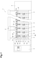
- an automatic winder 1 includes a plurality of winder units (yarn winders) 2 arranged side by side, a machine control device 3, a yarn-feeding bobbin feeder 4, a doffer 5, and a blower box not depicted.
- the machine control device 3 is configured to be able to perform communication with each of the winder units 2.
- An operator of the automatic winder 1 can, by operating the machine control device 3 as appropriate, centrally manage the multiple winder units 2.
- the machine control device 3 controls the operation of the yarn-feeding bobbin feeder 4 and the doffer 5.
- the yarn-feeding bobbin feeder 4 sets yarn feeding bobbins 21 one by one onto a transport tray 26.
- the yarn-feeding bobbin feeder 4 feeds the yarn feeding bobbin 21 that is set onto the transport tray 26 to each of the winder units 2.
- the doffer 5 travels, when a package 30 is fully wound (a state in which the specified amount of yarn Y is wound) in the winder unit 2, to the position of the relevant winder unit 2 and removes the fully wound package 30.
- the doffer 5 sets a winding bobbin 22 on which the yarn Y is not wound to the relevant winder unit 2 from which the package 30 has been removed.
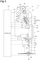
- the winder unit 2 includes a yarn feeding section (feeding section) 6, a yarn storage device 40, a detection unit 50, a cover 47, a package forming section (winding section) 8, a waxing device 70, and a controller 25.
- the yarn Y on the yarn feeding bobbin 21 of the yarn feeding section 6 is unwound and the unwound yarn Y is once stored in the yarn storage device 40, and thereafter the package forming section 8 draws out the yarn Y stored in the yarn storage device 40 and winds it onto the winding bobbin 22 to form the package 30.
- the yarn feeding section 6 is configured to support the yarn feeding bobbin 21 set in the transport tray 26 at a predetermined position and to unwind the yarn Y from the yarn feeding bobbin 21.
- the yarn feeding section 6 discharges, when all the yarn Y is unwound from the yarn feeding bobbin 21, the core tube of the yarn feeding bobbin 21 on which no yarn Y is wound and receives a supply of new yarn for the feeding bobbin 21 from the yarn-feeding bobbin feeder 4.
- the yarn storage device 40 is arranged in the middle of a yarn path formed between the yarn feeding section 6 and the package forming section 8.
- the yarn storage device 40 is provided on the upstream side in the traveling direction of the yarn Y with respect to the waxing device 70.
- the yarn storage device 40 winds the yarn Y that has been unwound in the yarn feeding section 6 and temporarily stores it.
- the yarn storage device 40 feeds the stored yarn Y to the package forming section 8.
- the yarn storage device 40 includes a storage roller 41 capable of winding the yarn Y, a drive motor 45 that rotatively drives the storage roller 41, and the cover 47.
- the storage roller 41 winds the yarn Y around a storage area A of an outer peripheral surface 41d in the storage roller 41 and temporarily stores the yarn Y.
- the storage roller 41 is rotatively supported on the machine stand (frame) of the automatic winder 1 around a rotation axis C1 that is slightly inclined with respect to the horizontal direction. As illustrated in FIG. 2 and FIG. 3 , on both axial end sides of the storage roller 41, respective tapered portions 41a and 41b are formed for which the diameter expands as it approaches the end.
- a portion between the two tapered portions 41a and 41b is a cylindrical portion 41c for which the diameter is constant.
- the outer peripheral surface 41d of the cylindrical portion 41c is a storage area A around which the yarn Y is wound.
- the outer peripheral surface 41d of the cylindrical portion 41c is mirror-finished. Due to the two tapered portions 41a and 41b on both end sides, the yarn Y wound around the cylindrical portion 41c is prevented from falling out.
- a ring member 42 is wound around.
- the ring member 42 is annularly formed by rubber, for example.
- the ring member 42 is attached to the boundary portion between the cylindrical portion 41c and the tapered portion 41b on the distal end side.
- the ring member 42 is a tension ring that surrounds the yarn Y drawn out from the storage roller 41 by the package forming section 8 and comes into contact with the relevant yarn Y to provide resistance.
- the ring member 42 is attached to the cylindrical portion 41c by an elastic force that tightens inward in the radial direction of the ring member 42.
- the ring member 42 provides resistance to the yarn Y drawn out from the storage roller 41 by the relevant elastic force. Due to the ring member 42, appropriate tension is provided to the yarn Y drawn out from the storage roller 41 and the unwinding of the yarn Y from the storage roller 41 is stabilized.
- a first recess (recess) 43a is provided in the outer peripheral surface 41d of the storage roller 41 in an area straddling the mounting position of the ring member 42 in the direction along the rotation axis C1. That is, viewed from outside the radial direction of the storage roller 41, the first recess 43a is provided so as to pass through the mounting position of the ring member 42 and is intersecting the relevant mounting position, and a portion of the first recess 43a overlaps the relevant mounting position.
- the first recess 43a in this case, constitutes a groove portion extending in the direction along the rotation axis C1 from one end of the storage roller 41 to the other end.
- the first recess 43a has the same cross-sectional shape in the longitudinal direction of the first recess 43a and is formed in a substantially rectangular shape in cross-section, for example.
- a second recess (recess) 43b is further provided on the outer peripheral surface 41d of the storage roller 41.
- the second recess (recessed portion) 43b is a recess (what is called downgage) provided to prevent the formation of a dent (what is called sink mark) when forming a boss to which a magnet for a sensor is embedded or a reinforcing rib on an inner surface 41g of the cylindrical portion 41c.
- the drive motor 45 rotates the storage roller 41 in the direction to wind the yarn Y from the yarn feeding section 6.
- the drive motor 45 can also rotate the storage roller 41 in the direction opposite to the relevant winding direction.
- the drive motor 45 is a position-controllable motor, such as a DC brushless motor, stepping motor, or servo motor.
- a downstream-yarn blowing section 80 is arranged Near the tapered portion 41a at one end side of the storage roller 41 (upstream side in the storage roller 41).
- the downstream-yarn blowing section 80 is arranged close to the outer peripheral surface 41d of the storage roller 41. During normal yarn winding, the yarn of the yarn feeding section 6 side passes through the downstream-yarn blowing section 80 and is guided to the tapered portion 41a at one end of the storage roller 41.
- the yarn Y guided by the downstream-yarn blowing section 80 to the tapered portion 41a on one end side of the storage roller 41 successively winds around while pushing up the previous yarn layer from the one end side (upstream side) of the cylindrical portion 41c.
- the yarn Y already wound on the outer peripheral surface 41d of the storage roller 41 is pushed by the newly wound yarn Y and sent to the other end side (downstream side) in sequence. Consequently, on the outer peripheral surface of the cylindrical portion 41c of the storage roller 41, the yarn Y aligns in a spiral shape and winds with regularity from one end side toward the other end side.
- the yarn Y wound around the storage roller 41 is drawn out and sent toward the downstream side (to the package forming section 8 side).
- the yarn Y on the storage roller 41 is drawn downstream side via a drawing guide 37 that is located on the extension line of the rotation axis C1 of the storage roller 41.
- the yarn Y wound around the storage roller 41 is unwound passing between the storage roller 41 and the above-described ring member 42. Accordingly, appropriate tension is applied to the yarn Y to be unwound.
- a detection section 53 is arranged near the outer peripheral surface 41d of the cylindrical portion 41c of the storage roller 41.
- the detection section 53 can detect that the yarn Y on the storage roller 41 has been greater than or equal to a predetermined upper limit amount and that the yarn Y has fallen below a predetermined lower limit amount.
- the detection section 53 may have a detection range from the above-described upper limit amount to the above-described lower limit amount.
- the detection range may be a wider range including a portion exceeding the above-described upper limit amount to a portion below the above-described lower limit amount. This allows the detection of excess amounts with respect to the above-described upper limit value, for example.
- the controller 25 controls, based on the detection result of the detection section 53, the drive motor 45 so that the storage amount (winding amount) of the storage roller 41 falls between the above-described upper limit amount and the above-described lower limit amount.
- the detection section 53 detects the yarn Y wound around the outer peripheral surface 41d of the storage roller 41. As illustrated in FIG. 4A through FIG. 4C , the detection section 53 forms the detection unit 50 together with a light emitting section 55 that emits light toward the storage roller 41. That is, the detection unit 50 is made up of the detection section 53 and the light emitting section 55.
- the detection section 53 and the light emitting section 55 are accommodated in a housing 51 and are fixed to the machine stand of the automatic winder 1.
- the detection section 53 has a line sensor 53A and a lens 53B that makes the incident light contract.
- the detection area of the line sensor 53A is a linear section S1 in the storage area A that connects between an end 41f of the storage area A on the upstream side in the traveling direction of the yarn Y and an end 41e of the storage area A on the downstream side in the traveling direction of the yarn Y.
- the line sensor 53A detects the presence or absence of the yarn Y in the above-described linear section S1. Examples of the line sensor 53A include a CCD image sensor or CMOS image sensor that acquires light intensity by photodiodes arrayed in a row.
- the line sensor 53A receives light through the lens 53B that makes the incident light contract.
- the line sensor 53A is provided so that the extending direction of the linear section S1 is parallel to the extending direction of the rotation axis C1, but the line sensor 53A may be provided so that the extending direction of the linear section S1 intersects the extending direction of the rotation axis C1.
- the light emitting section 55 has two light sources 55B and 55B and an optical waveguide 55C that converts the light emitted from the two light sources 55B and 55B into plane emission and emits it toward the storage roller 41.
- Some of the constituent elements of the optical waveguide 55C include a diffusion plate, such as an acrylic plate that guides the light.
- Examples of the two light sources 55B and 55B are light emitting diodes (LEDs) and are provided on an LED substrate 55A. The number of light sources is not limited to two.
- the line sensor 53A is provided at a position on which the light from the light emitting section 55 reflected by the outer peripheral surface 41d of the storage roller 41 is not incident and the light from the light emitting section 55 reflected by the yarn Y stored on the storage roller 41 is incident.
- the light emitting section 55 emits, as illustrated in FIG. 4C , light at an irradiation angle ⁇ in the range of 0° to 30°, for example.
- the line sensor 53A is arranged so that the light from the light emitting section 55 reflected by the outer peripheral surface 41d of the storage roller 41 is not incident" means that the line sensor 53A is arranged at a position on which the light emitted from the light emitting section 55 at the above-described angle is totally reflected by the outer peripheral surface 41d of the storage roller 41 and the light reflected by the outer peripheral surface 41d of the storage roller 41 is not incident.
- one straight line orthogonal to the rotation axis C1 is virtually set as a first straight line L1
- one straight line parallel to the first straight line L1 and tangent to the outer peripheral surface 41d of the storage roller 41 is virtually set as a second straight line L2.
- the light emitting section 55 is arranged on the first straight line L1 or between the line sensor 53A and the first straight line L1 in the array direction of the first straight line L1 and the second straight line L2. This allows the light emitting section 55 to emit light to a portion of the storage roller 41 located between the first straight line L1 and the second straight line L2.
- the line sensor 53A is arranged between the second straight line L2 and the first straight line L1.
- the light-receiving direction of the line sensor 53A is substantially parallel to the first straight line L1. In other words, on the line sensor 53A, the light is incident from the direction substantially parallel to the first straight line L1.
- the cover 47 is arranged, in the array direction of the first straight line L1 and the second straight line L2, in the area opposite to the side on which the first straight line L1 is arranged with respect to the second straight line L2.
- the cover 47 is provided so as to face a portion of the outer peripheral surface 41d of the storage roller 41.
- the cover 47 is provided in at least a portion in the traveling direction of the light from the light emitting section 55 that is reflected by the outer peripheral surface 41d of the storage roller 41.
- the cover 47 may be provided in at least a portion in the traveling direction of the light from the light emitting section 55 that is not reflected by the outer peripheral surface 41d of the storage roller 41.
- At least a portion of a facing surface 47a that is a point on the cover 47 on which the light from the light emitting section 55 is incident is formed to be in a color (for example, black) that lowers the reflectivity of the light.
- the surrounding of the yarn storage device 40 may be configured so that no structure that reflects the light toward the traveling direction of the light from the light emitting section 55 is arranged. Even when a structure that reflects the light to the traveling direction of the light from the light emitting section 55 is arranged, if the structure is arranged in a position where the reflected light is sufficiently attenuated when reaching the line sensor 53A, the light reflected from the yarn Y can be prevented from being not properly detected.
- the package forming section 8 includes a cradle 23 configured to allow the winding bobbin 22 to be attached and a traverse drum 24 that drives the winding bobbin 22 while traversing the yarn Y.
- the package forming section 8 constitutes the winding section.
- the cradle 23 rotatively supports the winding bobbin 22 (or the package 30).
- the cradle 23 is configured to allow the outer peripheral surface of the supported package 30 to come in contact with the outer peripheral surface of the traverse drum 24.
- the traverse drum 24 is driven to rotate by a drive source not depicted (such as an electric motor) and rotates in a state of being in contact with the outer peripheral surface of the winding bobbin 22 or the package 30, causing the winding bobbin 22 to rotate in a driven manner.
- a drive source not depicted such as an electric motor
- a traverse groove not depicted is formed on the outer peripheral surface of the traverse drum 24, a traverse groove not depicted is formed.
- the yarn Y can be traversed (traversing) at a predetermined width by the traverse groove. With the foregoing configuration, the yarn Y can be wound onto the winding bobbin 22 while traversing, and the package 30 of a predetermined shape can be formed.
- the waxing device 70 is arranged between the yarn storage device 40 and the package forming section 8.
- the waxing device 70 applies wax to the yarn Y traveling from the yarn storage device 40 toward the package forming section 8.
- the winder unit 2 includes various devices in the yarn path from the yarn feeding section 6 to the package forming section 8 via the yarn storage device 40. Specifically, arranged in the yarn path (yarn traveling path) of the yarn Y are, in order from the yarn feeding section 6 side upstream toward the yarn storage device 40 side downstream, an unwinding assist device 10, a lower yarn feeler 11, a tension applying section 12, a capturing device 13, a splicing device 14, a yarn monitoring device 16, and the downstream-yarn blowing section 80.
- the unwinding assist device 10 assists in unwinding of the yarn Y, by bringing a movable member 27 into contact with a balloon formed at the top of the yarn feeding bobbin 21 by the yarn Y unwound from the yarn feeding bobbin 21 being swung around, and by appropriately controlling the size of the relevant balloon.
- the lower yarn feeler 11 is arranged at a position close to the unwinding assist device 10 on the downstream side of the unwinding assist device 10.
- the lower yarn feeler 11 defines the presence of the yarn Y fed from the unwinding assist device 10.
- the tension applying section 12 applies a predetermined tension to the traveling yarn Y.
- the tension applying section 12 applies, based on the tension of the yarn Y detected by the tension sensor not depicted, the predetermined tension to the yarn Y.
- the tension applying section 12 is configured as a gate type composed of movable comb teeth arranged against fixed comb teeth.
- the tension applying section 12 imparts a predetermined resistance by making the yarn Y travel between the comb teeth.
- the movable side comb teeth are configured to be movable by a solenoid, for example, so that the comb teeth are in an engaged state or released state. This allows the tension applying section 12 to adjust the tension applied to the yarn Y.
- the configuration of the tension applying section 12 is not particularly limited and may be a disk-type tension applying section, for example.
- the capturing device 13 is arranged on the downstream side of the tension applying section 12.
- the capturing device 13 has a first capturing section 13A and a second capturing section 13B.
- the first capturing section 13A and the second capturing section 13B are integrated together and configured as a single component.
- Each of the first capturing section 13A and the second capturing section 13B is connected to a negative pressure source not depicted.
- the first capturing section 13A is configured as a cylindrical member in which an opening is formed at the distal end portion.
- the first capturing section 13A generates a suction airflow during yarn splicing and suctions and captures the yarn Y on the yarn storage device 40 side.
- the second capturing section 13B is configured as a cylindrical member in which an opening is formed at the distal end portion.
- the second capturing section 13B is provided to be swingable.
- the second capturing section 13B swings between a capturing position (first position) (indicated by the solid line in FIG. 2 ) at which the yarn Y fed from the unwinding assist device 10 is captured and a guiding position (second position) (indicated by the dashed line in FIG. 2 ) at which the yarn Y is guided to the splicing device 14.
- the capturing position may also be a standby position of the second capturing section 13B.
- the second capturing section 13B generates, at the capturing position, in a state of being close to the yarn path on the downstream side of the lower yarn feeler 11, a suction airflow on the distal end side of the second capturing section 13B, and suctions and captures a yarn end from the yarn feeding bobbin 21.
- the second capturing section 13B suctions and captures the yarn end on the yarn feeding bobbin 21 side of the cut yarn Y.
- the second capturing section 13B may be configured, by generating a suction airflow on the distal end side of the second capturing section 13B, to suction and remove fluff or the like attached to the traveling yarn Y.
- an auxiliary blowing section 28 that blows the yarn end to a position on the downstream side of the lower yarn feeler 11 (distal end of the second capturing section 13B) is provided.
- the auxiliary blowing section 28 jets out compressed air into the inside of the transport tray 26 formed in a hollow shape and the yarn feeding bobbin 21, and forms, at the distal end of the yarn feeding bobbin 21, an airflow that blows the yarn Y of the relevant yarn feeding bobbin 21 toward the lower yarn feeler 11 side.
- the yarn end on the relevant yarn feeding bobbin 21 side can be reliably sent toward the lower yarn feeler 11 side.
- the splicing device 14 splices separated yarn Y.
- the splicing device 14 splices the yarn Y on the yarn feeding bobbin 21 side and the yarn Y on the yarn storage device 40 side together when the yarn Y between the yarn feeding bobbin 21 and the yarn storage device 40 is separated, such as in yarn cutting at which the yarn monitoring device 16 detects a yarn defect and cuts the yarn Y with the cutter 15, in yarn breakage at which the yarn Y being unwound from the yarn feeding bobbin 21 is broken, in replacing the yarn feeding bobbin 21, or the like.
- the splicing device 14 is arranged at a position slightly retracted from the yarn path.
- the splicing device 14 can connect the introduced yarn ends to each other, making the yarn Y in a continuous state.
- a device that uses fluid, such as compressed air and the like, or a mechanical-type device can be used.
- the yarn monitoring device 16 detects, by monitoring the thickness or the like of the yarn Y with appropriate sensors, yarn defects, such as slubs or mixtures of foreign matters.
- the cutter 15 is arranged.
- the cutter 15 cuts the yarn Y immediately when the yarn monitoring device 16 detects a yarn defect.
- the cutter 15 and the yarn monitoring device 16 are housed in a common housing 19.
- the housing 19 that accommodates the yarn monitoring device 16 is arranged on the downstream side of the splicing device 14.
- the downstream-yarn blowing section 80 is an air sucker device arranged at a position close to the yarn storage device 40 on the upstream side of the yarn storage device 40.
- the downstream-yarn blowing section 80 forms, by jetting out compressed air, an airflow that blows, after sucking a yarn end on the yarn storage device 40 side that resides on the storage area A of the storage roller 41, the yarn end away and sends it up to the first capturing section 13A.
- the downstream-yarn blowing section 80 includes a thin cylindrical guide member (omitted to depict) inside through which the yarn Y can be passed and a yarn guiding member 60 that is a curved cylindrical member. At one end of the guide member, the outlet of the yarn Y is formed.
- the yarn guiding member 60 is provided to be close to the outlet of the downstream-yarn blowing section 80. At both ends of the yarn guiding member 60 in the longitudinal direction, openings are each formed.
- the yarn guiding member 60 is arranged in a state in which the opening on one end side of the yarn guiding member 60 faces the outlet of the downstream-yarn blowing section 80 and the opening on the other end side of the yarn guiding member 60 faces the first capturing section 13A.
- a guiding path is formed inside the yarn guiding member 60.
- the guiding path connects the openings at both ends of the yarn guiding member 60 so as to bypass the yarn monitoring device 16, the yarn splicing device 14, and the like.
- the downstream-yarn blowing section 80, the yarn guiding member 60, and the first capturing section 13A constitute a storage-side yarn end capturing device 75.
- the downstream-yarn blowing section 80 captures the yarn Y on the yarn storage device 40 side and blows it away to the guiding path of the yarn guiding member 60. Then, the downstream-yarn blowing section 80 draws out the yarn Y along the relevant guiding path to cause the yarn Y to be captured by the first capturing section 13A. As a through slit, not depicted, is formed over the entire length of the yarn guiding member 60, in a state in which the first capturing section 13A is let to capture the yarn Y, the relevant yarn Y can be drawn out from the inside of the yarn guiding member 60. As in the foregoing, by the downstream-yarn blowing section 80, the yarn Y on the yarn storage device 40 side can be blown and guided toward the yarn splicing device 14 side.
- Each winder unit 2 includes the controller 25.
- the controller 25 includes hardware, such as a CPU, ROM, and RAM, not depicted. In the RAM, software, such as control programs is stored.
- the controller 25 controls each constituent of the winder unit 2 through the collaboration of hardware and software.
- the controller 25 is configured to be able to perform communication with the machine control device 3. This allows the machine control device 3 to centrally manage the operation of the multiple winder units 2 included in the automatic winder 1.
- the controller 25 in the present embodiment determines the presence or absence of the yarn Y on the outer peripheral surface 41d (storage area A) of the storage roller 41.
- the controller 25 determines, based on the detection result by the line sensor 53A, the presence or absence of the yarn Y on the outer peripheral surface 41d.
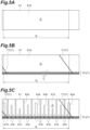
- FIG. 5A is a diagram in which the outer peripheral surface 41d of the storage roller 41 is planarly expanded so as to partially overlap in the rotational direction.
- the line sensor 53A detects the presence or absence of the yarn Y in the range R indicated in FIG. 5A .
- the controller 25 rotates the storage roller 41 one round at a low speed (below 200 rpm) and determines, based on the detection result by the line sensor 53A when the storage roller 41 is rotated one round, the presence or absence of the yarn Y on the outer peripheral surface 41d.
- the storage roller 41 may be rotated one round at a high speed (200 rpm or more) and, based on the detection result by the line sensor 53A when the storage roller 41 is rotated one round, the presence or absence of the yarn Y on the outer peripheral surface 41d may be determined.
- the line sensor 53A in the present embodiment with the storage roller 41 that rotates at a high speed, the effect of reflected light by the first recess 43a and the second recess 43b is reduced.
- the detection of the storage amount can be performed by ignoring the reflected light by the first recess 43a and the second recess 43b. In this case, as illustrated in FIG.
- the controller 25 when the yarn Y is not present on the outer peripheral surface 41d of the storage roller 41, the light emitted from the light emitting section 55 reflects toward the cover 47 side, without reflecting toward the line sensor 53A side even when reflected by the outer peripheral surface 41d as in the foregoing. Instead, when the yarn Y is present on the outer peripheral surface 41d, the light reflected by the yarn Y reflects toward the line sensor 53A side, and the reflected light is detected by the line sensor 53A.
- the detection result by the line sensor 53A at this time is acquired by the controller 25 as the data illustrated in FIG. 6 , for example.
- the areas where relatively more light is detected that is, the areas where whitish images are acquired when converted to BMP images
- the areas where relatively less light is detected that is, the areas where blackish images are acquired when converted to BMP images, indicate the areas where the yarn (white yarn) Y is not detected.
- the pixel position (pixel) in the detection result of the line sensor 53A indicates the position in the linear section S1.
- the controller 25 can, based on the detection result by the line sensor 53A, determine where the yarn Y is present and where the yarn Y is not present in the linear section S1. Thus, the controller 25 can, based on the amount of light detected by the line sensor 53A, accurately detect the presence or absence of the yarn Y in the range R indicated in FIG. 5B .
- the first recess 43a and the second recess 43b are formed on the outer peripheral surface 41d of the storage roller 41 in the present embodiment.
- the controller 25 determines that, by detecting that the first recess 43a that is the reference has rotated one round, the storage roller 41 has rotated one round.
- the controller 25 can, by the amount of rotation of the motor or by providing a marker (for example, magnetic) at the location of the recesses, determine the position of the first recess 43a and the second recess 43b.
- the light reflected by the first recess 43a and the second recess 43b may reflect toward the line sensor 53A side. In this case, the controller 25 is unable to detect the presence or absence of the yarn Y accurately, even if it is detected based on the detection result by the line sensor 53A.
- the controller 25 in the present embodiment determines the presence or absence of the yarn Y on the outer peripheral surface 41d based on the detection result by the line sensor 53A at a position different from the first recess 43a and the second recess 43b. In detail, the controller 25 determines the presence or absence of the yarn Y on the outer peripheral surface 41d based on the detection results by the line sensor 53A in all areas where the first recess 43a nor the second recess 43b are not formed. In more detail, as illustrated in FIG. 5C , on the outer peripheral surface 41d of the storage roller 41, a plurality of recesses (first recess 43a and second recess 43b) are formed along the rotational direction of the storage roller 41.
- a plurality of connecting portions 41h that are the areas between the recesses adjacent in the rotational direction are formed.
- the controller 25 determines the presence or absence of the yarn Y in the storage area A based on the detection results by the line sensor 53A in at least some areas of each of the connecting portions 41h.
- the controller 25 may, in the areas where the first recess 43a and the second recess 43b are not present, acquire the data by the line sensor 53A in a state in which the rotation of the storage roller 41 is stopped.
- the controller 25 can, by the amount of rotation of the motor or by providing a marker (for example, magnetic) at the location of the recesses, grasp the positions where the first recess 43a and the second recess 43b are not present.
- the controller 25 may acquire the data by the line sensor 53A while intermittently rotating the storage roller 41.
- the controller 25 may, by rotating the storage roller 41 at a low speed, detect only the necessary points.
- the controller 25 may make the line sensor 53A perform detection at all times by rotating the storage roller 41 and may perform no process of determining the presence or absence of the yarn Y on the outer peripheral surface 41d only at the points of the first recess 43a and the second recess 43b.
- the controller 25 determines whether sloughing is occurring.
- the controller 25 presumes, based on the amount of the yarn Y fed from the yarn feeding section 6 and the amount of the yarn Y wound by the package forming section 8, information on the yarn Y stored on the storage roller 41. Then, the controller 25 determines, based on the information on the yarn Y presumed and the detection result by the line sensor 53A, whether the yarn Y is uniformly wound around the outer peripheral surface 41d.
- Examples of the information on the yarn stored on the storage roller 41 include the storage amount, the length of yarn, the width of the area around which the yarn Y is wound on the outer peripheral surface 41d, and the like.
- the controller 25 presumes, based on the average of the difference between the rotational speed of the storage roller 41 and the rotational speed of the winding bobbin 22, the information on the yarn Y stored on the storage roller 41. Furthermore, the information on the yarn Y stored on the storage roller 41 may be presumed based on the value obtained by multiplying the time that the yarn Y is detected by the yarn monitoring device 16 or the lower yarn feeler 11 by the yarn speed (unwinding speed) and the value obtained by providing a sensor on the downstream side of the storage roller 41 and by multiplying the detection time of the sensor by the yarn speed (winding speed), for example. As the yarn speed, in this case, is not constant at all times, it is preferable to use an average speed.
- sloughing refers to a condition in which the yarn Y is not unwound stably from the storage roller 41 but is unwound all at once with several layers of the yarn Y entangled in each other as if jumping through a hoop.
- a yarn lump portion refers to a condition in which the yarn Y wound around the outer peripheral surface 41d of the storage roller 41 is not uniform along the rotation axis C1 of the storage roller 41 and the yarn Y is wound in a state of overlapping in the direction orthogonal to the rotation axis C1 of the storage roller 41.
- the controller 25 determines that sloughing is occurring in the yarn storage device 40, when a difference D obtained by subtracting a presumed storage amount S from a detected storage amount C becomes greater than a sloughing-determination storage amount T1, that is, in the portion circled in FIG. 7A .
- the presumed storage amount S refers to the storage amount V of the yarn Y as the information on the yarn Y
- the detected storage amount C refers to the storage amount V of the yarn Y calculated based on the detection results by the line sensor 53A.
- the fact that the difference D is greater than the sloughing-determination storage amount T1 means that, relative to the width when the yarn Y that is wound around the outer peripheral surface 41d of the storage roller 41 is wound around uniformly, the actual winding width is greater. That is, it can be determined that sloughing is occurring. As illustrated in FIG.
- the controller 25 determines that sloughing is occurring in the yarn storage device 40, when the difference D obtained by subtracting the presumed storage amount S from the detected storage amount C becomes greater than the sloughing-determination storage amount T1, that is, in the portion circled in FIG. 7B . As for the reasons why it can be determined, it is the same as those of the process of the storage amount V of the yarn Y being increased in the yarn storage device 40.
- the value obtained by multiplying by time the average of the difference between the rotational speed of the storage roller 41 and the rotational speed of the winding bobbin 22 in a certain period is the presumed storage amount S.
- the difference D may be determined based on the detection result by the line sensor 53A and the storage height of the yarn Y stored on the storage roller 41.
- the storage height can be calculated by dividing the presumed storage amount S by the circumferential length of the storage roller 41 in order to calculate the number of turns of the yarn Y on the storage roller 41, and by multiplying the relevant number of turns of the yarn Y by the thickness of the yarn Y.
- the controller 25 may, in place of the above-described detecting method of sloughing, based on the detection result by the line sensor 53A, determine that sloughing is occurring in the yarn storage device 40 when the amount of movement per unit time of the downstream-most position YP of the yarn Y stored on the outer peripheral surface 41d when the state of FIG. 8A shifted to the state of FIG. 8B is greater than a sloughing-determination movement amount T2.
- the controller 25 determines whether a yarn lump portion is occurring. As illustrated in FIG. 9A , in the process of the storage amount V of the yarn Y being increased in the yarn storage device 40, the controller 25 determines that a yarn lump portion is occurring in the yarn storage device 40, when the difference D obtained by subtracting the detected storage amount C from the presumed storage amount S becomes greater than a yarn-lump portion determination storage amount T3, that is, in the portion circled in FIG. 9A .
- the fact that the difference D is greater than the yarn-lump portion determination storage amount T3 means that, relative to the width when the yarn Y that is wound around the outer peripheral surface 41d of the storage roller 41 is wound around uniformly, the actual winding width is smaller. That is, it can be determined that a yarn lump portion is occurring.
- FIG. 9B in the process of the storage amount V of the yarn Y in the yarn storage device 40 being decreased, it is determined that a yarn lump portion is occurring in the yarn storage device 40, when the difference D obtained by subtracting the detected storage volume C from the presumed storage volume S becomes greater than the yarn-lump portion determination storage amount T3, that is, in the circled portion in FIG. 9B .
- the line sensor 53A that detects the yarn Y wound around the outer peripheral surface 41d of the storage roller 41 is configured with the line sensor 53A that detects the presence or absence of yarn in the linear section S1 connecting between an upstream end in the traveling direction of the yarn and a downstream end in the traveling direction of the yarn in the outer peripheral surface 41d (storage area A).
- the storage amount V of the yarn Y wound in the yarn storage device 40 can be detected.
- the winder unit 2 of the above-described embodiment has, as illustrated in FIG. 4B , the light emitting section 55 that emits light toward the storage roller 41. This makes it possible to provide strength and weakness (contrast) to the light received by the line sensor 53A, so that the detection accuracy of the yarn Y by the controller 25 can be enhanced.
- the light emitting section 55 of the winder unit 2 in the above-described embodiment has, as illustrated in FIG. 4B , the two light sources 55B and 55B and the optical waveguide 55C that converts the light emitted from the two light sources 55B and 55B into plane emission and emits it toward the storage roller 41, so that the light emitted from the light emitting section 55 can be made uniform. This allows the accuracy in detecting the yarn Y to be enhanced.
- the line sensor 53A of the winder unit in the above-described embodiment is, as illustrated in FIG. 4A , configured to receive light through the lens 53B that makes the incident light contract, so that the detection section 53 can be compactly provided.
- the line sensor 53A of the winder unit 2 in the above-described embodiment is, as illustrated in FIG. 4C , provided at a position on which the light from the light emitting section 55 reflected by the outer peripheral surface 41d of the storage roller 41 is not incident and the light from the light emitting section 55 reflected by the yarn Y stored on the storage roller 41 is incident.
- This allows the detection accuracy of the white-based yarn Y for which the light is easily reflected by the yarn Y wound around the storage roller 41 to be enhanced.
- the presence or absence of the yarn Y is detected based on the reflected light from only the yarn Y stored on the storage roller 41. This reduces the incidence of the light reflected from portions other than the yarn Y onto the line sensor 53A, so that the detection accuracy of the yarn Y can be enhanced.
- the yarn storage device 40 of the winder unit 2 in the above-described embodiment includes, as illustrated in FIG. 4C , the cover 47 facing a portion of the outer peripheral surface 41d of the storage roller 41, and the relevant cover 47 is provided in a portion in the traveling direction of the light from the light emitting section 55 reflected by the outer peripheral surface 41d of the storage roller 41.
- This makes it possible to prevent fluff generated at the storage roller 41 from scattering to various locations and prevent, by controlling the airflow generated by the rotation of the storage roller 41, a yarn end from contacting the surrounding constituents.
- the cover 47 is able to absorb the light from the light emitting section 55 reflected by the outer peripheral surface 41d of the storage roller 41. This reduces the incidence of the light reflected from the portions other than the yarn Y (disturbance light) onto the line sensor 53A, so that the detection accuracy of the yarn Y by the controller 25 can be enhanced.
- the controller 25 of the winder unit 2 in the above-described embodiment rotates the storage roller 41 at least one round and determines, based on the detection result by the line sensor 53A when the storage roller 41 is rotated one round, the presence or absence of the yarn Y in storage area A. This allows the presence or absence of the yarn Y to be detected in the entire area of the outer peripheral surface 41d that constitutes the storage roller 41, so that the detection accuracy of the yarn Y by the controller 25 can be enhanced.
- a defect may be found in the yarn Y and the like, and when the yarn Y stored on the storage roller 41 is unwound or removed, the yarn Y may remain on the storage roller 41.
- the yarn Y may be tangled or yarn breakage may occur.
- the operation of storing the yarn Y on the storage roller 41 may be prohibited.
- the execution of the operation to store the yarn Y on the storage roller 41 in a state in which the yarn Y remains on the storage roller 41 can be stopped before it happens, so that, in the winder unit 2, it is possible to prevent the yarn Y from getting tangled or yarn breakage from occurring.
- the controller 25 it may be configured to inform the operator of that fact.
- the controller 25 of the winder unit 2 in the above-described embodiment determines that, by detecting that the first recess 43a that is the reference has rotated one round, the storage roller 41 has rotated one round. This allows the controller 25 to determine that the storage roller 41 has rotated one round in a simple method.
- the controller 25 of the winder unit 2 in the above-described embodiment determines, based on the detection result by the line sensor 53A at positions different from the first recess 43a and the second recess 43b, the presence or absence of the yarn Y in the storage area A. This makes it possible to reduce the possibility of the controller 25 misjudging the presence or absence of the yarn Y due to detection and misdetection of the first recess 43a and the second recess 43b by the line sensor 53A.
- the controller 25 of the winder unit 2 in the above-described embodiment determines, based on the detection result by the line sensor 53A at all positions at which the first recess 43a nor the second recess 43b are not formed, the presence or absence of the yarn Y in the storage area A. This allows the detection accuracy of the yarn Y to be enhanced, in the storage roller 41 for which the first recess 43a and the second recess 43b are formed on the outer peripheral surface 41d.
- the controller 25 of the winder unit 2 in the above-described embodiment determines, based on the information on the yarn stored on the storage roller 41 that is presumed based on the amount of the yarn Y fed from the yarn feeding section 6 and the amount of the yarn Y wound by the package forming section 8 (presumed storage amount S) and the detection result by the line sensor 53A, whether the yarn Y is uniformly wound in the storage area A. This makes it possible to determine, with a simple configuration, whether the yarn Y is uniformly wound in the storage area A. Furthermore, the controller 25 presumes, based on the average of the difference between the rotational speed of the storage roller 41 and the rotational speed of the winding bobbin 22, the information on the yarn Y stored on the storage roller 41 (presumed storage amount S). This makes it possible to accurately presume the information on the yarn Y stored on the storage roller 41.
- the controller 25 of the winder unit 2 in the above-described embodiment determines that, as illustrated in FIG. 7A and FIG. 7B , when the difference D obtained by subtracting the presumed storage amount S from the detected storage amount C becomes greater than the sloughing-determination storage amount T1, sloughing is occurring in the yarn storage device 40. This makes it possible to determine that, with a simple configuration, sloughing is occurring at the storage roller 41.
- the controller 25 of the winder unit 2 in the above embodiment determines that, as illustrated in FIG. 8A and FIG. 8B , based on the detection result by the line sensor 53A, when the amount of movement per unit time of the downstream-most position YP of the yarn Y stored in the storage area A becomes greater than the sloughing-determination movement amount T2, sloughing is occurring in the yarn storage device 40. In this case, also, it is possible to determine that, with a simple configuration, sloughing is occurring at the storage roller 41.
- the tension fluctuation of the yarn Y is increased or the yarn Y from the storage roller 41 is not properly unwound, thereby increasing the possibility of the occurrence of yarn breakage.
- the controller 25 when confirmed by the controller 25 that sloughing is occurring, by executing tension control of the yarn Y or speed control of the yarn Y, the yarn breakage can be stopped before it occurs.
- the controller 25 when it is confirmed by the controller 25 that sloughing is occurring, it may be configured to inform the operator of that fact.
- the controller 25 of the winder unit 2 in the above-described embodiment determines that, as illustrated in FIG. 8A and FIG. 8B , when the difference D obtained by subtracting the detected storage amount C from the presumed storage amount S becomes greater than the yarn-lump portion determination storage amount T3, a yarn lump portion is occurring in the yarn storage device 40. This makes it possible to determine that, with a simple configuration, a yarn lump portion is occurring at the storage roller 41.
- the above-described sloughing is triggered or the yarn Y from the storage roller 41 is not unwound properly, thereby increasing the possibility of the occurrence of yarn breakage.
- the controller 25 when confirmed by the controller 25 that a yarn lump portion is present, by executing a control such that the rotation of the storage roller 41 is stopped and the yarn lump portion is wound by the package forming section 8 arranged downstream of the storage roller 41, the above-described yarn breakage can be prevented before it happens.
- the controller 25 When confirmed by the controller 25 that a yarn lump portion is occurring, it may be configured to inform the operator of that fact.
- the sloughing portion may be wound by the package forming section 8.
- the line sensor 53A In the winder unit 2 of the above-described embodiment, an example of the line sensor 53A that is provided, as illustrated in FIG. 4C , at a position on which the light from the light emitting section 55 reflected by the outer peripheral surface 41d of the storage roller 41 is not incident and the light from the light emitting section 55 reflected by the yarn Y stored on the storage roller 41 is incident has been described, but the embodiment is not limited thereto.
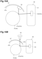
- the line sensor 53A may, as illustrated in FIG. 10A , be provided at a position on which the light from the light emitting section 55 reflected by the outer peripheral surface 41d of the storage roller 41 is incident.
- the detection accuracy of black-based (colored) yarn Y in particular that is difficult for the light to be reflected by the yarn Y wound around the storage roller 41 can be enhanced.
- the controller 25 when the yarn Y is present on the outer peripheral surface 41d of the storage roller 41, the light emitted from the light emitting section 55 is absorbed by the yarn Y and is not reflected toward the line sensor 53A, for example. Meanwhile, when no yarn Y is present on the outer peripheral surface 41d of the storage roller 41, the light reflected by the outer peripheral surface 41d is reflected toward the line sensor 53A, and the reflected light is detected by the line sensor 53A.
- the detection result by the line sensor 53A at this time is acquired by the controller 25 as the data illustrated in FIG. 11 , for example.
- areas where relatively more light is detected that is, areas where whitish images are acquired when converted to BMP images, indicate areas where no yarn (black yarn) is detected.
- Areas where relatively less light is detected that is, areas where blackish images are acquired when converted to BMP images, indicate areas where the yarn (black yarn) is detected.
- the light from the light emitting section 55 may be made incident on the storage roller 41 through the slit 47b and the light from the light emitting section 55 reflected by the outer peripheral surface 41d of the storage roller 41 may be made incident on the line sensor 53A.
- the above-described embodiment is of a configuration suitable for the use of white-based yarn Y having a relatively high reflectance
- the above-described first modification and the second modification are of a configuration suitable for the use of black-based (colored) yarn Y having a relatively low reflectance.
- a third modification an example of a configuration suitable for a case in which the use is desired while replacing white-based yarn Y and black-based (colored) yarn Y will be described.
- the winder unit 2 according to the third modification may add a colored-yarn light emitting section 551 (55) that is the light emitting section 55 for black-based (colored) yarn Y detection according to the second modification, and the cover 47, to the configuration of the above-described embodiment including a white-based yarn light emitting section 552 (55) that is the light emitting section 55 for white-based yarn Y detection. Accordingly, it may be configured so that both white-based yarn Y and black-based (colored) yarn Y can be detected by a single line sensor 53A (a detection section 53).
- the light emitted from the colored-yarn light emitting section 551 in the above-described embodiment may be incident on the slit 47b and adversely affect the detection result by the line sensor 53A (cause of false detection). Therefore, in the third modification, as illustrated in FIG. 12A , it is configured so that a door 48 is provided in the slit 47b and the door 48 is opened and closed by an actuator (cylinder, solenoid, or the like). Then, the controller 25 controls the actuator so as to open the door 48 when detecting black-based (colored) yarn Y and to close the door 48 when detecting white-based yarn Y.
- an actuator cylinder, solenoid, or the like
- the winder unit 2 includes a controller as a mode switching section capable of selectively switching between a white-based yarn detection mode that is a detection mode for white-based yarn and a colored-yarn detection mode that is a detection mode for colored yarn.
- the controller when the white-based yarn detection mode is selected, causes the white-based yarn light emitting section 552 to emit light and determines that the yarn Y is present in the portion where the light is received by the line sensor 53A (a detection section 53).
- the controller when the colored-yarn detection mode is selected, causes the colored-yarn light emitting section 551 to emit light and determines that the yarn Y is present in the portion where the light is not received by the line sensor 53A.
- the winder unit 2 according to the third modification is configured so that the above-described detection mode can be set via the machine control device 3 (or a device similar to the machine control device 3), for example. In the winder unit 2, by setting the relevant mode, the state of the door and the detection method that are suitable for detecting white-based yarn Y and the state of the door and the detection method that are suitable for detecting black-based (colored) yarn Y can be switched.
- the end of the cover 47 in place of the configuration of the third modification including the slit 47b and the door 48, by configuring the end of the cover 47 to be extendable, it may be controlled so that the end of the cover 47 is retracted when detecting black-based (colored) yarn Y and the end of the cover 47 is extended when detecting white-based yarn Y.
- the operator may install a screen or the like depending on the yarn type (black-based or white-based) to be used.
- the winder unit 2 according to a fourth modification is, as with the winder unit 2 according to the third modification, an example of a configuration suitable for a case in which the use is desired while replacing white-based yarn Y and black-based (colored) yarn Y.
- the configuration of the winder unit 2 according to the fourth modification is different from that of the winder unit 2 according to the third modification in that, as illustrated in FIG. 12B , a white-based yarn detection line sensor 532 that detects light emitted by the white-based yarn light emitting section 552 (55) and a colored yarn detection line sensor 531 that detects light emitted by the colored-yarn light emitting section 551 (55) are provided.
- the colored-yarn light emitting section 551 irradiates the outer peripheral surface 41d of the storage roller 41 with light via the slit 47b.
- the colored yarn detection line sensor 531 is provided at a position on which the light from the colored-yarn light emitting section 551 reflected by the outer peripheral surface 41d of the storage roller 41 is incident.
- the white-based yarn light emitting section 552 irradiates the outer peripheral surface 41d of the storage roller 41 with light.
- the white-based yarn detection line sensor 532 is provided at a position on which the light from the white-based yarn light emitting section 552 reflected by the outer peripheral surface 41d of the storage roller 41 is not incident and the light from the white-based yarn light emitting section 552 reflected by the yarn Y stored on the storage roller 41 is incident.
- the controller 25 When black-based (colored) yarn Y is used and when it is determined whether the yarn Y is stored on the storage roller 41, the controller 25 opens the door 48. When white-based yarn Y is used or when it is not determined whether black-based (colored) yarn Y is stored on the storage roller 41, the controller 25 closes the door 48. This makes it possible, in a single winder unit 2, to be used while replacing white-based yarn Y and black-based (colored) yarn Y.
- the slit 47b may be provided with a transparent window, in which case the transmittance of the transparent window can be between 0.4 and 0.6, for example.
- the transparent window can be used also in the second modification and the third modification.
- the yarn storage device 40 may be configured without the cover 47 being provided.
- the detection unit 50 made up of the detection section 53 and the light emitting section 55 may be provided to be movable relative to the storage roller 41.
- the movement of the detection unit 50 includes at least one of horizontal movement and rotational movement.
- the detection unit 50 may be configured to be manually movable or may be configured to be movable by an actuator or the like.
- the detection unit 50 is moved to a position at which the light emitting section 55 emits light onto the outer peripheral surface 41d of the storage roller 41 and at which the light from the light emitting section 55 reflected by the outer peripheral surface 41d of the storage roller 41 is incident on the line sensor 53A.
- white-based yarn Y as illustrated in FIG.
- the detection unit 50 is moved to a position at which the light emitting section 55 emits light onto the outer peripheral surface 41d of the storage roller 41 and at which the light from the light emitting section 55 reflected by the outer peripheral surface 41d of the storage roller 41 is not incident on the line sensor 53A and the light from the light emitting section 55 reflected by the yarn Y stored on the storage roller 41 is incident thereon.
- the winder unit 2 according to the fifth modification it makes it possible, in a single winder unit 2, to be used while replacing white-based yarn Y and black-based (colored) yarn Y.
- the method of detecting the yarn Y may be changed depending on the mirror-finishing (plating) in the first recess 43a and the second recess 43b provided on the outer peripheral surface 41d of the storage roller 41.
- black-based (colored) yarn Y may be detected in such an arrangement of the detection unit 50 as illustrated in FIG. 13A .
- black-based (colored) yarn Y it is preferable to use the detection result of the line sensor 53A in the portions where the first recess 43a and the second recess 43b are not present, but it is not limited thereto.
- white-based yarn Y may be detected in such an arrangement of the detection unit 50 as illustrated in FIG. 13B .
- white-based yarn Y it is preferable to use the detection result of the line sensor 53A in the portions where the first recess 43a and the second recess 43b are not present, but it is not limited thereto.
- the white-based yarn Y may be detected in such an arrangement of the detection unit 50 as illustrated in FIG. 13A .
- the white-based yarn Y is detected.
- black-based (colored) yarn Y may be detected.
- the white-based yarn Y may be detected in the portions where the first recess 43a and the second recess 43b are not present.
Landscapes
- Engineering & Computer Science (AREA)
- Textile Engineering (AREA)
- Quality & Reliability (AREA)
- Filamentary Materials, Packages, And Safety Devices Therefor (AREA)
- Forwarding And Storing Of Filamentary Material (AREA)
Abstract
Description
- One aspect of the present disclosure relates to a yarn winder.
- There has been known a yarn winder (yarn winding apparatus) that includes a yarn feeding section in which a yarn feeding bobbin is supported, a yarn storage device that unwinds yarn from the yarn feeding bobbin supported by the yarn feeding section and winds the unwound yarn, a splicing device that splices a yarn end of the yarn on the yarn feeding bobbin side with a yarn end of the yarn storage device side, and a yarn winding section that winds yarn to form a package. As such a yarn winder, a yarn winder in which an upper limit sensor that detects that the yarn on a storage roller exceeded a predetermined upper limit amount and a lower limit sensor that detects that the yarn on the storage roller fell below a predetermined lower limit amount are arranged near the outer peripheral surface of a cylindrical portion of the storage roller has been disclosed in Patent Literature 1 (
Japanese Unexamined Patent Publication No. 2013-241231 Patent Literature 1 controls a drive motor, based on the detection results of these sensors, so that the yarn storage amount (winding amount) of the storage roller falls between the above-described upper limit amount and the above-described lower limit amount. - In such a yarn winder there is a desire to achieve finer control or detect winding abnormality in the yarn storage device by detecting not only the upper limit value or lower limit value of the yarn storage amount as in the foregoing but also the detailed storage amount of the yarn wound in the yarn storage device. In this case, increasing the number of the above-described sensors, for example, would make it possible to detect the storage amount in detail, but the configuration would become complex and the cost would increase.
- An object of one aspect of the present disclosure, therefore, is to provide a yarn winder capable of detecting the storage amount of yarn wound in the yarn storage device with a simple configuration and at a low cost.
- A yarn winder according to one aspect of the present disclosure includes a feeding section capable of feeding yarn, a winding section configured to wind yarn fed from the feeding section and form a package, a yarn storage device provided in a yarn path formed between the feeding section and the winding section and configured to wind, by rotating a storage roller, the yarn fed out from the feeding section around a storage area in an outer peripheral surface of the storage roller to temporarily store the yarn, a controller configured to control rotation of the storage roller, and a detection section configured to detect the yarn wound around the outer peripheral surface of the storage roller, wherein a detection area of the detection section is a linear section in the storage area connecting between an upstream end side of the storage area in a traveling direction of the yarn and a downstream end side of the storage area in the traveling direction of the yarn relative to the upstream end side of the storage area, and the detection section is a line sensor configured to detect the presence or absence of the yarn in the linear section.
- This makes it possible to detect the presence or absence of the yarn in the above-described linear section in the storage area without providing sensors that detect the presence or absence of the yarn at various locations in the storage area. As a result, with a simple configuration and at a low cost, the storage amount of the yarn wound in the yarn storage device can be detected.
- In the yarn winder according to one aspect of the present disclosure, the line sensor may be arranged so that the extending direction of the detection area of the detection section is parallel to the extending direction of the rotation axis of the storage roller. In this configuration, the line sensor detects light reflected by the storage roller or the yarn in the area parallel to the extending direction of the rotation axis of the storage roller. Thus, the way of reflection of the storage roller or the yarn in the above-described linear section can be made uniform.
- The yarn winder according to one aspect of the present disclosure may further include a light emitting section configured to emit light toward the storage roller, wherein the line sensor receives light reflected by the storage roller or the yarn, and the controller may determine that, when the line sensor receives light (detects incident of light), the light received by the line sensor is the light reflected by one of the storage roller and the yarn, and may determine, based on the result of the above-described determination, the presence or absence of the yarn in the linear section. In this configuration, by determining the presence or absence of the yarn based on the detection result of the light reflected by the storage roller or the yarn, the process can be simplified.
- In the yarn winder according to one aspect of the present disclosure, the light emitting section may have two light sources and an optical waveguide that converts the light emitted from the two light sources into plane emission and emits the light toward the storage roller, and the line sensor may receive the light through a lens that makes incident light contract. In this configuration, as the light emitted from the light emitting section can be made uniform, the accuracy in detecting the yarn can be enhanced, and the detection section can be compactly provided.
- In the yarn winder according to one aspect of the present disclosure, the line sensor may be provided at a position on which light from the light emitting section reflected by the outer peripheral surface of the storage roller is not incident and light from the light emitting section reflected by the yarn stored on the storage roller is incident. In this configuration, the detection accuracy of white-based yarn for which the light is easily reflected by the yarn wound around the storage roller can be enhanced. In detail, the presence or absence of the yarn is detected based on the reflected light from the yarn stored on the storage roller, and the incidence of the light reflected from portions other than yarn onto the line sensor is reduced, so that the detection accuracy of the yarn can be enhanced.
- The yarn winder according to one aspect of the present disclosure may further include a cover facing a portion of the outer peripheral surface of the storage roller, and the cover may be provided in at least a portion in the traveling direction of light from the light emitting section reflected by the outer peripheral surface of the storage roller. In this configuration, the cover is provided to prevent fluff generated at the storage roller from scattering and the fluff from depositing on the surrounding constituents. Furthermore, in this configuration, by controlling the airflow generated by the rotation of the storage roller by the cover, a yarn end can be prevented from contacting the surrounding constituents. In this configuration, the cover is provided in the traveling direction of the light from the light emitting section reflected by the outer peripheral surface of the storage roller, so that the line sensor can be prevented from detecting the light from the light emitting section reflected by the outer peripheral surface of the storage roller.
- In the yarn winder according to one aspect of the present disclosure, in a planar view seen from a direction in which the rotation axis of the storage roller extends, when one straight line orthogonal to the rotation axis is virtually set as a first straight line and one straight line parallel to the first straight line and tangent to the outer peripheral surface of the storage roller is virtually set as a second straight line, the line sensor may be arranged between the first straight line and the second straight line, the light emitting section may be arranged on the first straight line or between the line sensor and the first straight line in the array direction of the first straight line and the second straight line, and the cover may be arranged in the area opposite to the side on which the first straight line is arranged with respect to the second straight line in the array direction of the first straight line and the second straight line. In this configuration, the line sensor is arranged between the first straight line and the second straight line. Thus, the line sensor receives the light from a direction parallel to a straight line passing through the center of the storage roller and different from the straight line passing through the center of the storage roller in the array direction. That is, the light reflected by the storage roller or the yarn at a curved portion of the storage roller can be separated, so that the detection accuracy of the yarn can be enhanced.
- In the yarn winder according to one aspect of the present disclosure, a point in the cover on which light from the light emitting section is incident may be in black. In this configuration, the light from the light emitting section reflected by the outer peripheral surface of the storage roller is absorbed by the cover. Thus, the incidence of the light reflected from portions other than the yarn onto the line sensor is reduced, so that the detection accuracy of the yarn can be enhanced.
- In the yarn winder according to one aspect of the present disclosure, the light emitting section may have a white-based yarn light emitting section and a colored-yarn light emitting section, and the line sensor may be provided at a position on which light from the white-based yarn light emitting section reflected by the outer peripheral surface of the storage roller is not incident and light from the white-based yarn light emitting section reflected by the yarn stored on the storage roller is incident, and may be provided at a position on which light from the colored-yarn light emitting section reflected by the outer peripheral surface of the storage roller is incident. In this configuration, even when the yarn used in the yarn winder is white-based yarn or colored yarn, such as black, by switching the light emitting section to emit light between the white-based yarn light emitting section and the colored-yarn light emitting section, the presence or absence of the yarn can be detected with high accuracy.
- The yarn winder according to one aspect of the present disclosure may further include a mode switching section capable of selectively switching between a white-based yarn detection mode that is a detection mode for white-based yarn and a colored-yarn detection mode that is a detection mode for colored yarn, wherein the controller may, when the white-based yarn detection mode is selected in the mode switching section, cause the white-based yarn light emitting section to emit light and may determine that the yarn is present in a portion at which light is received by the line sensor and may, when the colored-yarn detection mode is selected in the mode switching section, cause the colored-yarn light emitting section to emit light and may determine that the yarn is present in a portion at which the light is not received by the line sensor. In this configuration, appropriate control and appropriate determination can be made in accordance with the detection mode for the yarn used in the yarn winder.
- In the yarn winder according to one aspect of the present disclosure, the line sensor may be provided at a position on which light from the light emitting section reflected by the outer peripheral surface of the storage roller is incident. In this configuration, the detection accuracy of black-based (colored) yarn that is difficult for the light to be reflected by the yarn wound around the storage roller can be enhanced.
- In the yarn winder according to one aspect of the present disclosure, the controller may cause the storage roller to rotate at least one round and may determine the presence or absence of the yarn in the storage area based on the detection result by the line sensor when the storage roller is rotated at least one round. In this configuration, it makes it possible to determine the presence or absence of the yarn in all or only necessary portions on the storage roller, and the outer peripheral surface constituting the storage roller can be evaluated.
- In the yarn winder according to one aspect of the present disclosure, at least one recess extending along the rotation axis direction of the storage roller may be formed on the outer peripheral surface of the storage roller, and the controller may determine that, by detecting that the recess that is a reference has rotated one round, the storage roller has rotated one round. In this configuration, it is possible to determine that the storage roller has rotated one round in a simple method.
- In the yarn winder according to one aspect of the present disclosure, the controller may determine, based on the detection result by the line sensor at a position different from the recess, the presence or absence of the yarn in the storage area. In this configuration, it is possible to reduce the controller misjudging the presence or absence of the yarn due to detection and misdetection of the recess by the line sensor, for example.
- In the yarn winder according to one aspect of the present disclosure, on the outer peripheral surface of the storage roller, a plurality of recesses may be formed along the rotational direction of the storage roller and a plurality of connecting portions that are areas between the recesses adjacent in the rotational direction may be formed, and the controller may determine, based on the detection result by the line sensor in at least a portion of the area of each of the connecting portions, the presence or absence of the yarn in the storage area. In this configuration, in the storage roller for which the recesses are formed on the outer peripheral surface, the detection accuracy of the yarn can be enhanced.
- In the yarn winder according to one aspect of the present disclosure, the controller may presume information on the yarn stored on the storage roller based on the amount of yarn fed from the feeding section and the amount of yarn wound by the winding section and may determine, based on the information on the yarn and the detection result by the line sensor, whether the yarn is uniformly wound in the storage area. In this configuration, with a simple configuration, it is possible to determine whether the yarn is uniformly wound in the storage area.
- In the yarn winder according to one aspect of the present disclosure, the winding section may form a package by rotating a winding bobbin to wind the yarn fed out from the yarn storage device onto the winding bobbin, and the controller may presume, based on an average of the difference between the rotational speed of the storage roller and the rotational speed of the winding bobbin, the information on the yarn stored on the storage roller. In this configuration, it is possible to accurately presume the information on the yarn stored on the storage roller.
- In the yarn winder according to one aspect of the present disclosure, the storage amount of the yarn as information on the yarn is a presumed storage amount and the storage amount of the yarn calculated based on the detection result by the line sensor is a detected storage amount, and the controller may determine that, when the difference obtained by subtracting the presumed storage amount from the detected storage amount becomes greater than a sloughing-determination storage amount, sloughing is occurring in the yarn storage device. Sloughing refers to a condition in which the yarn is not unwound stably from the storage roller but is unwound all at once with several layers of the yarn entangled in each other as if jumping through a hoop. In this configuration, with a simple configuration, it is possible to determine that sloughing is occurring at the storage roller.
- In the yarn winder according to one aspect of the present disclosure, the controller may determine that, based on the detection result by the line sensor, when the amount of movement per unit time of the downstream-most position of the yarn stored in the storage area becomes greater than a sloughing-determination movement amount (T2), sloughing is occurring in the yarn storage device. In this configuration, with a simple configuration, it is possible to determine that sloughing is occurring at the storage roller.
- In the yarn winder according to one aspect of the present disclosure, the storage amount of the yarn as information on the yarn is a presumed storage amount and the storage amount of the yarn calculated based on the detection result by the line sensor is a detected storage amount, and when the difference obtained by subtracting the detected storage amount from the presumed storage amount becomes greater than a yarn-lump portion determination storage amount, it may be determined that a yarn lump portion (what is called dumpling) is occurring in the yarn storage device. The yarn lump portion refers to a condition in which the yarn wound around the outer peripheral surface of the storage roller is not uniform and is wound in an overlapping manner. In this configuration, with a simple configuration, it is possible to determine that a yarn lump portion is occurring at the storage roller.
- According to one aspect of the present disclosure, with a simple configuration and at a low cost, it is possible to detect the storage amount of yarn wound in the yarn storage device.
-
-
FIG. 1 is a schematic front view illustrating an overall configuration of an automatic winder according to one embodiment; -
FIG. 2 is a schematic side view illustrating a winder unit according to the embodiment; -
FIG. 3 is a perspective view of a yarn storage device included in the winder unit; -
FIG. 4A is a diagram illustrating the arrangement relation between the yarn storage device and a detection section;FIG. 4B is a diagram illustrating the arrangement relation between the yarn storage device and a light emitting section;FIG. 4C is a diagram illustrating the arrangement relation between the yarn storage device and a detection unit; -
FIG. 5A is a diagram in which the outer peripheral surface of a storage roller is planarly expanded so as to partially overlap in a rotational direction;FIG. 5B is a diagram in which the outer peripheral surface of the storage roller is planarly expanded so as to partially overlap in the rotational direction when the yarn is present on the outer peripheral surface of the storage roller;FIG. 5C is a diagram in which the outer peripheral surface of the storage roller is planarly expanded so as to partially overlap in the rotational direction when the yarn and recessed portions are present on the outer peripheral surface of the storage roller; -
FIG. 6 is a diagram illustrating one example of results acquired by a line sensor; -
FIG. 7A is a diagram illustrating one example of the relation between a detected storage amount and a presumed storage amount in the process in which the storage amount of yarn in the yarn storage device increases;FIG. 7B is a diagram illustrating one example of the relation between the detected storage amount and the presumed storage amount in the process in which the storage amount of yarn in the yarn storage device decreases; -
FIG. 8A is a diagram illustrating one example of the relation between the detected storage amount and the presumed storage amount in the process in which the storage amount of yarn in the yarn storage device increases;FIG. 8B is a diagram illustrating one example of the relation between the detected storage amount and the presumed storage amount in the process in which the storage amount of yarn in the yarn storage device decreases; -
FIG. 9A and FIG. 9B are diagrams illustrating a downstream-most position of the yarn stored on the outer peripheral surface; -
FIG. 10A is a diagram illustrating the arrangement relation between the yarn storage device and the detection unit of the winder unit according to a first modification;FIG. 10B is a diagram illustrating the arrangement relation between the yarn storage device and the detection unit of the winder unit according to a second modification; -
FIG. 11 is a diagram illustrating one example of the acquired results by the line sensor according to the modifications; -
FIG. 12A is a diagram illustrating the arrangement relation between the yarn storage device and the detection unit of the winder unit according to a third modification;FIG. 12B is a diagram illustrating the arrangement relation between the yarn storage device and the detection unit of the winder unit according to a fourth modification; and -
FIG. 13A and FIG. 13B are diagrams illustrating the arrangement relation between the yarn storage device and the detection unit of the winder unit according to a fifth modification. - A preferred embodiment of the present disclosure will now be described in detail with reference to the accompanying drawings. In the description of drawings, identical or equivalent elements are designated by the same reference signs, and duplicate description is omitted. "Upstream" and "downstream" mean upstream and downstream, respectively, in the traveling direction of the yarn.
- As illustrated in
FIG. 1 , anautomatic winder 1 includes a plurality of winder units (yarn winders) 2 arranged side by side, amachine control device 3, a yarn-feedingbobbin feeder 4, a doffer 5, and a blower box not depicted. - The
machine control device 3 is configured to be able to perform communication with each of thewinder units 2. An operator of theautomatic winder 1 can, by operating themachine control device 3 as appropriate, centrally manage themultiple winder units 2. Themachine control device 3 controls the operation of the yarn-feedingbobbin feeder 4 and the doffer 5. - The yarn-feeding
bobbin feeder 4 setsyarn feeding bobbins 21 one by one onto atransport tray 26. The yarn-feedingbobbin feeder 4 feeds theyarn feeding bobbin 21 that is set onto thetransport tray 26 to each of thewinder units 2. - The doffer 5 travels, when a
package 30 is fully wound (a state in which the specified amount of yarn Y is wound) in thewinder unit 2, to the position of therelevant winder unit 2 and removes the fully woundpackage 30. The doffer 5 sets a windingbobbin 22 on which the yarn Y is not wound to therelevant winder unit 2 from which thepackage 30 has been removed. - Next, the configuration of the
winder unit 2 will be described. As illustrated inFIG. 2 , thewinder unit 2 includes a yarn feeding section (feeding section) 6, ayarn storage device 40, adetection unit 50, acover 47, a package forming section (winding section) 8, awaxing device 70, and acontroller 25. In thewinder unit 2, the yarn Y on theyarn feeding bobbin 21 of theyarn feeding section 6 is unwound and the unwound yarn Y is once stored in theyarn storage device 40, and thereafter thepackage forming section 8 draws out the yarn Y stored in theyarn storage device 40 and winds it onto the windingbobbin 22 to form thepackage 30. - The
yarn feeding section 6 is configured to support theyarn feeding bobbin 21 set in thetransport tray 26 at a predetermined position and to unwind the yarn Y from theyarn feeding bobbin 21. Theyarn feeding section 6 discharges, when all the yarn Y is unwound from theyarn feeding bobbin 21, the core tube of theyarn feeding bobbin 21 on which no yarn Y is wound and receives a supply of new yarn for the feedingbobbin 21 from the yarn-feedingbobbin feeder 4. - The
yarn storage device 40 is arranged in the middle of a yarn path formed between theyarn feeding section 6 and thepackage forming section 8. Theyarn storage device 40 is provided on the upstream side in the traveling direction of the yarn Y with respect to thewaxing device 70. Theyarn storage device 40 winds the yarn Y that has been unwound in theyarn feeding section 6 and temporarily stores it. Theyarn storage device 40 feeds the stored yarn Y to thepackage forming section 8. - The
yarn storage device 40 includes astorage roller 41 capable of winding the yarn Y, adrive motor 45 that rotatively drives thestorage roller 41, and thecover 47. Thestorage roller 41 winds the yarn Y around a storage area A of an outerperipheral surface 41d in thestorage roller 41 and temporarily stores the yarn Y. Thestorage roller 41 is rotatively supported on the machine stand (frame) of theautomatic winder 1 around a rotation axis C1 that is slightly inclined with respect to the horizontal direction. As illustrated inFIG. 2 andFIG. 3 , on both axial end sides of thestorage roller 41, respectivetapered portions tapered portions cylindrical portion 41c for which the diameter is constant. The outerperipheral surface 41d of thecylindrical portion 41c is a storage area A around which the yarn Y is wound. The outerperipheral surface 41d of thecylindrical portion 41c is mirror-finished. Due to the twotapered portions cylindrical portion 41c is prevented from falling out. - On the outer
peripheral surface 41d of thecylindrical portion 41c of thestorage roller 41, aring member 42 is wound around. Thering member 42 is annularly formed by rubber, for example. Thering member 42 is attached to the boundary portion between thecylindrical portion 41c and the taperedportion 41b on the distal end side. Thering member 42 is a tension ring that surrounds the yarn Y drawn out from thestorage roller 41 by thepackage forming section 8 and comes into contact with the relevant yarn Y to provide resistance. Thering member 42 is attached to thecylindrical portion 41c by an elastic force that tightens inward in the radial direction of thering member 42. Thering member 42 provides resistance to the yarn Y drawn out from thestorage roller 41 by the relevant elastic force. Due to thering member 42, appropriate tension is provided to the yarn Y drawn out from thestorage roller 41 and the unwinding of the yarn Y from thestorage roller 41 is stabilized. - In the outer
peripheral surface 41d of thestorage roller 41, in an area straddling the mounting position of thering member 42 in the direction along the rotation axis C1, a first recess (recess) 43a is provided. That is, viewed from outside the radial direction of thestorage roller 41, thefirst recess 43a is provided so as to pass through the mounting position of thering member 42 and is intersecting the relevant mounting position, and a portion of thefirst recess 43a overlaps the relevant mounting position. Thefirst recess 43a, in this case, constitutes a groove portion extending in the direction along the rotation axis C1 from one end of thestorage roller 41 to the other end. Thefirst recess 43a has the same cross-sectional shape in the longitudinal direction of thefirst recess 43a and is formed in a substantially rectangular shape in cross-section, for example. On the outerperipheral surface 41d of thestorage roller 41, a second recess (recess) 43b is further provided. The second recess (recessed portion) 43b is a recess (what is called downgage) provided to prevent the formation of a dent (what is called sink mark) when forming a boss to which a magnet for a sensor is embedded or a reinforcing rib on aninner surface 41g of thecylindrical portion 41c. - The
drive motor 45 rotates thestorage roller 41 in the direction to wind the yarn Y from theyarn feeding section 6. Thedrive motor 45 can also rotate thestorage roller 41 in the direction opposite to the relevant winding direction. Thedrive motor 45 is a position-controllable motor, such as a DC brushless motor, stepping motor, or servo motor. - Near the tapered
portion 41a at one end side of the storage roller 41 (upstream side in the storage roller 41), a downstream-yarn blowing section 80 is arranged. The downstream-yarn blowing section 80 is arranged close to the outerperipheral surface 41d of thestorage roller 41. During normal yarn winding, the yarn of theyarn feeding section 6 side passes through the downstream-yarn blowing section 80 and is guided to the taperedportion 41a at one end of thestorage roller 41. When thestorage roller 41 is rotated in one direction by driving thedrive motor 45, the yarn Y guided by the downstream-yarn blowing section 80 to the taperedportion 41a on one end side of thestorage roller 41 successively winds around while pushing up the previous yarn layer from the one end side (upstream side) of thecylindrical portion 41c. As a result, the yarn Y already wound on the outerperipheral surface 41d of thestorage roller 41 is pushed by the newly wound yarn Y and sent to the other end side (downstream side) in sequence. Consequently, on the outer peripheral surface of thecylindrical portion 41c of thestorage roller 41, the yarn Y aligns in a spiral shape and winds with regularity from one end side toward the other end side. - From the tapered
portion 41b at the other end side of the storage roller 41 (downstream side in the storage roller 41), the yarn Y wound around thestorage roller 41 is drawn out and sent toward the downstream side (to thepackage forming section 8 side). At the taperedportion 41b, the yarn Y on thestorage roller 41 is drawn downstream side via adrawing guide 37 that is located on the extension line of the rotation axis C1 of thestorage roller 41. The yarn Y wound around thestorage roller 41 is unwound passing between thestorage roller 41 and the above-describedring member 42. Accordingly, appropriate tension is applied to the yarn Y to be unwound. - A
detection section 53 is arranged near the outerperipheral surface 41d of thecylindrical portion 41c of thestorage roller 41. For example, thedetection section 53 can detect that the yarn Y on thestorage roller 41 has been greater than or equal to a predetermined upper limit amount and that the yarn Y has fallen below a predetermined lower limit amount. Thedetection section 53 may have a detection range from the above-described upper limit amount to the above-described lower limit amount. The detection range may be a wider range including a portion exceeding the above-described upper limit amount to a portion below the above-described lower limit amount. This allows the detection of excess amounts with respect to the above-described upper limit value, for example. In the present embodiment, from the detection range, it is detected that the yarn Y on thestorage roller 41 has been greater than or equal to the predetermined upper limit amount and that the yarn Y has fallen below the predetermined lower limit amount. The terms "greater than or equal to" and "below" in the foregoing can be used as "in excess of" and "less than or equal to" as appropriate. The detection result by thedetection section 53 is acquired by thecontroller 25. Thecontroller 25 controls, based on the detection result of thedetection section 53, thedrive motor 45 so that the storage amount (winding amount) of thestorage roller 41 falls between the above-described upper limit amount and the above-described lower limit amount. - The
detection section 53 detects the yarn Y wound around the outerperipheral surface 41d of thestorage roller 41. As illustrated inFIG. 4A through FIG. 4C , thedetection section 53 forms thedetection unit 50 together with alight emitting section 55 that emits light toward thestorage roller 41. That is, thedetection unit 50 is made up of thedetection section 53 and thelight emitting section 55. Thedetection section 53 and thelight emitting section 55 are accommodated in ahousing 51 and are fixed to the machine stand of theautomatic winder 1. - The
detection section 53 has aline sensor 53A and alens 53B that makes the incident light contract. The detection area of theline sensor 53A is a linear section S1 in the storage area A that connects between anend 41f of the storage area A on the upstream side in the traveling direction of the yarn Y and anend 41e of the storage area A on the downstream side in the traveling direction of the yarn Y. Theline sensor 53A detects the presence or absence of the yarn Y in the above-described linear section S1. Examples of theline sensor 53A include a CCD image sensor or CMOS image sensor that acquires light intensity by photodiodes arrayed in a row. Theline sensor 53A receives light through thelens 53B that makes the incident light contract. In the present embodiment, theline sensor 53A is provided so that the extending direction of the linear section S1 is parallel to the extending direction of the rotation axis C1, but theline sensor 53A may be provided so that the extending direction of the linear section S1 intersects the extending direction of the rotation axis C1. - The
light emitting section 55 has twolight sources optical waveguide 55C that converts the light emitted from the twolight sources storage roller 41. Some of the constituent elements of theoptical waveguide 55C include a diffusion plate, such as an acrylic plate that guides the light. Examples of the twolight sources LED substrate 55A. The number of light sources is not limited to two. - The
line sensor 53A is provided at a position on which the light from thelight emitting section 55 reflected by the outerperipheral surface 41d of thestorage roller 41 is not incident and the light from thelight emitting section 55 reflected by the yarn Y stored on thestorage roller 41 is incident. Thelight emitting section 55 emits, as illustrated inFIG. 4C , light at an irradiation angle θ in the range of 0° to 30°, for example. "Theline sensor 53A is arranged so that the light from thelight emitting section 55 reflected by the outerperipheral surface 41d of thestorage roller 41 is not incident" means that theline sensor 53A is arranged at a position on which the light emitted from thelight emitting section 55 at the above-described angle is totally reflected by the outerperipheral surface 41d of thestorage roller 41 and the light reflected by the outerperipheral surface 41d of thestorage roller 41 is not incident. - Now, one straight line orthogonal to the rotation axis C1 is virtually set as a first straight line L1, and one straight line parallel to the first straight line L1 and tangent to the outer
peripheral surface 41d of thestorage roller 41 is virtually set as a second straight line L2. In the present embodiment, in a planar view seen from the direction in which the rotation axis C1 of thestorage roller 41 extends, thelight emitting section 55 is arranged on the first straight line L1 or between theline sensor 53A and the first straight line L1 in the array direction of the first straight line L1 and the second straight line L2. This allows thelight emitting section 55 to emit light to a portion of thestorage roller 41 located between the first straight line L1 and the second straight line L2. Theline sensor 53A is arranged between the second straight line L2 and the first straight line L1. The light-receiving direction of theline sensor 53A is substantially parallel to the first straight line L1. In other words, on theline sensor 53A, the light is incident from the direction substantially parallel to the first straight line L1. Thecover 47 is arranged, in the array direction of the first straight line L1 and the second straight line L2, in the area opposite to the side on which the first straight line L1 is arranged with respect to the second straight line L2. - The
cover 47 is provided so as to face a portion of the outerperipheral surface 41d of thestorage roller 41. Thecover 47 is provided in at least a portion in the traveling direction of the light from thelight emitting section 55 that is reflected by the outerperipheral surface 41d of thestorage roller 41. Thecover 47 may be provided in at least a portion in the traveling direction of the light from thelight emitting section 55 that is not reflected by the outerperipheral surface 41d of thestorage roller 41. At least a portion of a facingsurface 47a that is a point on thecover 47 on which the light from thelight emitting section 55 is incident is formed to be in a color (for example, black) that lowers the reflectivity of the light. Lowering the reflectivity in such a manner allows the reflected light from thecover 47 to be prevented from being incident on thestorage roller 41. Consequently, this allows the light reflected from the yarn Y to be prevented from being not properly detected due to the light reflected by thecover 47 being detected by theline sensor 53A. - Even without providing the
cover 47, the surrounding of theyarn storage device 40 may be configured so that no structure that reflects the light toward the traveling direction of the light from thelight emitting section 55 is arranged. Even when a structure that reflects the light to the traveling direction of the light from thelight emitting section 55 is arranged, if the structure is arranged in a position where the reflected light is sufficiently attenuated when reaching theline sensor 53A, the light reflected from the yarn Y can be prevented from being not properly detected. - As illustrated in
FIG. 1 andFIG. 2 , thepackage forming section 8 includes acradle 23 configured to allow the windingbobbin 22 to be attached and atraverse drum 24 that drives the windingbobbin 22 while traversing the yarn Y. Thepackage forming section 8 constitutes the winding section. Thecradle 23 rotatively supports the winding bobbin 22 (or the package 30). Thecradle 23 is configured to allow the outer peripheral surface of the supportedpackage 30 to come in contact with the outer peripheral surface of thetraverse drum 24. - The
traverse drum 24 is driven to rotate by a drive source not depicted (such as an electric motor) and rotates in a state of being in contact with the outer peripheral surface of the windingbobbin 22 or thepackage 30, causing the windingbobbin 22 to rotate in a driven manner. This allows the yarn Y stored in theyarn storage device 40 to be unwound and drawn out, and to be wound onto the windingbobbin 22. On the outer peripheral surface of thetraverse drum 24, a traverse groove not depicted is formed. The yarn Y can be traversed (traversing) at a predetermined width by the traverse groove. With the foregoing configuration, the yarn Y can be wound onto the windingbobbin 22 while traversing, and thepackage 30 of a predetermined shape can be formed. - The waxing
device 70 is arranged between theyarn storage device 40 and thepackage forming section 8. The waxingdevice 70 applies wax to the yarn Y traveling from theyarn storage device 40 toward thepackage forming section 8. - The
winder unit 2 includes various devices in the yarn path from theyarn feeding section 6 to thepackage forming section 8 via theyarn storage device 40. Specifically, arranged in the yarn path (yarn traveling path) of the yarn Y are, in order from theyarn feeding section 6 side upstream toward theyarn storage device 40 side downstream, an unwindingassist device 10, alower yarn feeler 11, atension applying section 12, a capturingdevice 13, asplicing device 14, ayarn monitoring device 16, and the downstream-yarn blowing section 80. - The unwinding
assist device 10 assists in unwinding of the yarn Y, by bringing amovable member 27 into contact with a balloon formed at the top of theyarn feeding bobbin 21 by the yarn Y unwound from theyarn feeding bobbin 21 being swung around, and by appropriately controlling the size of the relevant balloon. - The
lower yarn feeler 11 is arranged at a position close to the unwinding assistdevice 10 on the downstream side of the unwinding assistdevice 10. Thelower yarn feeler 11 defines the presence of the yarn Y fed from the unwinding assistdevice 10. - The
tension applying section 12 applies a predetermined tension to the traveling yarn Y. Thetension applying section 12 applies, based on the tension of the yarn Y detected by the tension sensor not depicted, the predetermined tension to the yarn Y. Thetension applying section 12 is configured as a gate type composed of movable comb teeth arranged against fixed comb teeth. Thetension applying section 12 imparts a predetermined resistance by making the yarn Y travel between the comb teeth. The movable side comb teeth are configured to be movable by a solenoid, for example, so that the comb teeth are in an engaged state or released state. This allows thetension applying section 12 to adjust the tension applied to the yarn Y. The configuration of thetension applying section 12 is not particularly limited and may be a disk-type tension applying section, for example. - The capturing
device 13 is arranged on the downstream side of thetension applying section 12. The capturingdevice 13 has afirst capturing section 13A and asecond capturing section 13B. In the present embodiment, thefirst capturing section 13A and thesecond capturing section 13B are integrated together and configured as a single component. Each of thefirst capturing section 13A and thesecond capturing section 13B is connected to a negative pressure source not depicted. - The
first capturing section 13A is configured as a cylindrical member in which an opening is formed at the distal end portion. Thefirst capturing section 13A generates a suction airflow during yarn splicing and suctions and captures the yarn Y on theyarn storage device 40 side. - The
second capturing section 13B is configured as a cylindrical member in which an opening is formed at the distal end portion. Thesecond capturing section 13B is provided to be swingable. Thesecond capturing section 13B swings between a capturing position (first position) (indicated by the solid line inFIG. 2 ) at which the yarn Y fed from the unwinding assistdevice 10 is captured and a guiding position (second position) (indicated by the dashed line inFIG. 2 ) at which the yarn Y is guided to thesplicing device 14. The capturing position may also be a standby position of thesecond capturing section 13B. - The
second capturing section 13B generates, at the capturing position, in a state of being close to the yarn path on the downstream side of thelower yarn feeler 11, a suction airflow on the distal end side of thesecond capturing section 13B, and suctions and captures a yarn end from theyarn feeding bobbin 21. When the yarn Y is cut by acutter 15, thesecond capturing section 13B suctions and captures the yarn end on theyarn feeding bobbin 21 side of the cut yarn Y. Thesecond capturing section 13B may be configured, by generating a suction airflow on the distal end side of thesecond capturing section 13B, to suction and remove fluff or the like attached to the traveling yarn Y. - In capturing the yarn Y by the
second capturing section 13B, when it is immediately after a newyarn feeding bobbin 21 is fed to theyarn feeding section 6, anauxiliary blowing section 28 that blows the yarn end to a position on the downstream side of the lower yarn feeler 11 (distal end of thesecond capturing section 13B) is provided. - The
auxiliary blowing section 28 jets out compressed air into the inside of thetransport tray 26 formed in a hollow shape and theyarn feeding bobbin 21, and forms, at the distal end of theyarn feeding bobbin 21, an airflow that blows the yarn Y of the relevantyarn feeding bobbin 21 toward thelower yarn feeler 11 side. When the newly fedyarn feeding bobbin 21 is supported by theyarn feeding section 6, as theauxiliary blowing section 28 operates, the yarn end on the relevantyarn feeding bobbin 21 side can be reliably sent toward thelower yarn feeler 11 side. - The
splicing device 14 splices separated yarn Y. Thesplicing device 14 splices the yarn Y on theyarn feeding bobbin 21 side and the yarn Y on theyarn storage device 40 side together when the yarn Y between theyarn feeding bobbin 21 and theyarn storage device 40 is separated, such as in yarn cutting at which theyarn monitoring device 16 detects a yarn defect and cuts the yarn Y with thecutter 15, in yarn breakage at which the yarn Y being unwound from theyarn feeding bobbin 21 is broken, in replacing theyarn feeding bobbin 21, or the like. Thesplicing device 14 is arranged at a position slightly retracted from the yarn path. Thesplicing device 14 can connect the introduced yarn ends to each other, making the yarn Y in a continuous state. As thesplicing device 14, a device that uses fluid, such as compressed air and the like, or a mechanical-type device can be used. - The
yarn monitoring device 16 detects, by monitoring the thickness or the like of the yarn Y with appropriate sensors, yarn defects, such as slubs or mixtures of foreign matters. At a position close to theyarn monitoring device 16 on the upstream side of the relevantyarn monitoring device 16, thecutter 15 is arranged. Thecutter 15 cuts the yarn Y immediately when theyarn monitoring device 16 detects a yarn defect. Thecutter 15 and theyarn monitoring device 16 are housed in acommon housing 19. Thehousing 19 that accommodates theyarn monitoring device 16 is arranged on the downstream side of thesplicing device 14. - The downstream-
yarn blowing section 80 is an air sucker device arranged at a position close to theyarn storage device 40 on the upstream side of theyarn storage device 40. The downstream-yarn blowing section 80 forms, by jetting out compressed air, an airflow that blows, after sucking a yarn end on theyarn storage device 40 side that resides on the storage area A of thestorage roller 41, the yarn end away and sends it up to thefirst capturing section 13A. Specifically, the downstream-yarn blowing section 80 includes a thin cylindrical guide member (omitted to depict) inside through which the yarn Y can be passed and ayarn guiding member 60 that is a curved cylindrical member. At one end of the guide member, the outlet of the yarn Y is formed. Theyarn guiding member 60 is provided to be close to the outlet of the downstream-yarn blowing section 80. At both ends of theyarn guiding member 60 in the longitudinal direction, openings are each formed. - The
yarn guiding member 60 is arranged in a state in which the opening on one end side of theyarn guiding member 60 faces the outlet of the downstream-yarn blowing section 80 and the opening on the other end side of theyarn guiding member 60 faces thefirst capturing section 13A. Inside theyarn guiding member 60, a guiding path is formed. The guiding path connects the openings at both ends of theyarn guiding member 60 so as to bypass theyarn monitoring device 16, theyarn splicing device 14, and the like. The downstream-yarn blowing section 80, theyarn guiding member 60, and thefirst capturing section 13A constitute a storage-side yarnend capturing device 75. - When the yarn Y is in a separated state between the
yarn feeding bobbin 21 and theyarn storage device 40, the downstream-yarn blowing section 80 captures the yarn Y on theyarn storage device 40 side and blows it away to the guiding path of theyarn guiding member 60. Then, the downstream-yarn blowing section 80 draws out the yarn Y along the relevant guiding path to cause the yarn Y to be captured by thefirst capturing section 13A. As a through slit, not depicted, is formed over the entire length of theyarn guiding member 60, in a state in which thefirst capturing section 13A is let to capture the yarn Y, the relevant yarn Y can be drawn out from the inside of theyarn guiding member 60. As in the foregoing, by the downstream-yarn blowing section 80, the yarn Y on theyarn storage device 40 side can be blown and guided toward theyarn splicing device 14 side. - Each
winder unit 2 includes thecontroller 25. Thecontroller 25 includes hardware, such as a CPU, ROM, and RAM, not depicted. In the RAM, software, such as control programs is stored. Thecontroller 25 controls each constituent of thewinder unit 2 through the collaboration of hardware and software. Thecontroller 25 is configured to be able to perform communication with themachine control device 3. This allows themachine control device 3 to centrally manage the operation of themultiple winder units 2 included in theautomatic winder 1. - The
controller 25 in the present embodiment determines the presence or absence of the yarn Y on the outerperipheral surface 41d (storage area A) of thestorage roller 41. Thecontroller 25 determines, based on the detection result by theline sensor 53A, the presence or absence of the yarn Y on the outerperipheral surface 41d.FIG. 5A is a diagram in which the outerperipheral surface 41d of thestorage roller 41 is planarly expanded so as to partially overlap in the rotational direction. Theline sensor 53A detects the presence or absence of the yarn Y in the range R indicated inFIG. 5A . In more detail, thecontroller 25 rotates thestorage roller 41 one round at a low speed (below 200 rpm) and determines, based on the detection result by theline sensor 53A when thestorage roller 41 is rotated one round, the presence or absence of the yarn Y on the outerperipheral surface 41d. - The
storage roller 41 may be rotated one round at a high speed (200 rpm or more) and, based on the detection result by theline sensor 53A when thestorage roller 41 is rotated one round, the presence or absence of the yarn Y on the outerperipheral surface 41d may be determined. In theline sensor 53A in the present embodiment, with thestorage roller 41 that rotates at a high speed, the effect of reflected light by thefirst recess 43a and thesecond recess 43b is reduced. Thus, the detection of the storage amount can be performed by ignoring the reflected light by thefirst recess 43a and thesecond recess 43b. In this case, as illustrated inFIG. 5C , in the portion YC where the yarn Y is dense, it is more likely to be detected by theline sensor 53A because the reflected light increases. Meanwhile, at a single yarn portion Y1 that is drawn out from the portion YC where the yarn Y is dense, it is difficult to be detected by theline sensor 53A because the reflected light decreases. - For example, as for the
controller 25, as illustrated inFIG. 4C , when the yarn Y is not present on the outerperipheral surface 41d of thestorage roller 41, the light emitted from thelight emitting section 55 reflects toward thecover 47 side, without reflecting toward theline sensor 53A side even when reflected by the outerperipheral surface 41d as in the foregoing. Instead, when the yarn Y is present on the outerperipheral surface 41d, the light reflected by the yarn Y reflects toward theline sensor 53A side, and the reflected light is detected by theline sensor 53A. - The detection result by the
line sensor 53A at this time is acquired by thecontroller 25 as the data illustrated inFIG. 6 , for example. In the data illustrated inFIG. 6 , the areas where relatively more light is detected, that is, the areas where whitish images are acquired when converted to BMP images, indicate the areas where the yarn (white yarn) Y is detected. The areas where relatively less light is detected, that is, the areas where blackish images are acquired when converted to BMP images, indicate the areas where the yarn (white yarn) Y is not detected. The pixel position (pixel) in the detection result of theline sensor 53A indicates the position in the linear section S1. That is, thecontroller 25 can, based on the detection result by theline sensor 53A, determine where the yarn Y is present and where the yarn Y is not present in the linear section S1. Thus, thecontroller 25 can, based on the amount of light detected by theline sensor 53A, accurately detect the presence or absence of the yarn Y in the range R indicated inFIG. 5B . - As in the foregoing, on the outer
peripheral surface 41d of thestorage roller 41 in the present embodiment, thefirst recess 43a and thesecond recess 43b are formed. Thecontroller 25 determines that, by detecting that thefirst recess 43a that is the reference has rotated one round, thestorage roller 41 has rotated one round. Thecontroller 25 can, by the amount of rotation of the motor or by providing a marker (for example, magnetic) at the location of the recesses, determine the position of thefirst recess 43a and thesecond recess 43b. However, the light reflected by thefirst recess 43a and thesecond recess 43b may reflect toward theline sensor 53A side. In this case, thecontroller 25 is unable to detect the presence or absence of the yarn Y accurately, even if it is detected based on the detection result by theline sensor 53A. - Therefore, the
controller 25 in the present embodiment determines the presence or absence of the yarn Y on the outerperipheral surface 41d based on the detection result by theline sensor 53A at a position different from thefirst recess 43a and thesecond recess 43b. In detail, thecontroller 25 determines the presence or absence of the yarn Y on the outerperipheral surface 41d based on the detection results by theline sensor 53A in all areas where thefirst recess 43a nor thesecond recess 43b are not formed. In more detail, as illustrated inFIG. 5C , on the outerperipheral surface 41d of thestorage roller 41, a plurality of recesses (first recess 43a andsecond recess 43b) are formed along the rotational direction of thestorage roller 41. Furthermore, on the outerperipheral surface 41d of thestorage roller 41, a plurality of connectingportions 41h that are the areas between the recesses adjacent in the rotational direction are formed. Thecontroller 25 determines the presence or absence of the yarn Y in the storage area A based on the detection results by theline sensor 53A in at least some areas of each of the connectingportions 41h. - The
controller 25 may, in the areas where thefirst recess 43a and thesecond recess 43b are not present, acquire the data by theline sensor 53A in a state in which the rotation of thestorage roller 41 is stopped. Thecontroller 25 can, by the amount of rotation of the motor or by providing a marker (for example, magnetic) at the location of the recesses, grasp the positions where thefirst recess 43a and thesecond recess 43b are not present. In other words, thecontroller 25 may acquire the data by theline sensor 53A while intermittently rotating thestorage roller 41. Thecontroller 25 may, by rotating thestorage roller 41 at a low speed, detect only the necessary points. Thecontroller 25 may make theline sensor 53A perform detection at all times by rotating thestorage roller 41 and may perform no process of determining the presence or absence of the yarn Y on the outerperipheral surface 41d only at the points of thefirst recess 43a and thesecond recess 43b. - Next, a method by which the
controller 25 determines whether sloughing is occurring will be described. Thecontroller 25 presumes, based on the amount of the yarn Y fed from theyarn feeding section 6 and the amount of the yarn Y wound by thepackage forming section 8, information on the yarn Y stored on thestorage roller 41. Then, thecontroller 25 determines, based on the information on the yarn Y presumed and the detection result by theline sensor 53A, whether the yarn Y is uniformly wound around the outerperipheral surface 41d. Examples of the information on the yarn stored on thestorage roller 41 include the storage amount, the length of yarn, the width of the area around which the yarn Y is wound on the outerperipheral surface 41d, and the like. Thecontroller 25 presumes, based on the average of the difference between the rotational speed of thestorage roller 41 and the rotational speed of the windingbobbin 22, the information on the yarn Y stored on thestorage roller 41. Furthermore, the information on the yarn Y stored on thestorage roller 41 may be presumed based on the value obtained by multiplying the time that the yarn Y is detected by theyarn monitoring device 16 or thelower yarn feeler 11 by the yarn speed (unwinding speed) and the value obtained by providing a sensor on the downstream side of thestorage roller 41 and by multiplying the detection time of the sensor by the yarn speed (winding speed), for example. As the yarn speed, in this case, is not constant at all times, it is preferable to use an average speed. - Specific examples of cases in which the yarn Y is not uniformly wound around the outer
peripheral surface 41d include sloughing and yarn lump portions. Sloughing refers to a condition in which the yarn Y is not unwound stably from thestorage roller 41 but is unwound all at once with several layers of the yarn Y entangled in each other as if jumping through a hoop. A yarn lump portion refers to a condition in which the yarn Y wound around the outerperipheral surface 41d of thestorage roller 41 is not uniform along the rotation axis C1 of thestorage roller 41 and the yarn Y is wound in a state of overlapping in the direction orthogonal to the rotation axis C1 of thestorage roller 41. - As illustrated in
FIG. 7A , in the process of the storage amount V of the yarn Y being increased in theyarn storage device 40, thecontroller 25 determines that sloughing is occurring in theyarn storage device 40, when a difference D obtained by subtracting a presumed storage amount S from a detected storage amount C becomes greater than a sloughing-determination storage amount T1, that is, in the portion circled inFIG. 7A . In more detail, if it became greater than the threshold value only once, there is a possibility of false detection, so when it is detected a plurality of times in a row (for example, three times in a row) or a plurality of times in a predetermined period (for example, two out of three detection opportunities are greater than the threshold value, but it does not need to be twice in a row), it is determined that sloughing is occurring. Naturally, it may be determined that sloughing is occurring when it is detected even once. - The presumed storage amount S refers to the storage amount V of the yarn Y as the information on the yarn Y, and the detected storage amount C refers to the storage amount V of the yarn Y calculated based on the detection results by the
line sensor 53A. The fact that the difference D is greater than the sloughing-determination storage amount T1 means that, relative to the width when the yarn Y that is wound around the outerperipheral surface 41d of thestorage roller 41 is wound around uniformly, the actual winding width is greater. That is, it can be determined that sloughing is occurring. As illustrated inFIG. 7B , in the process of the storage amount V of the yarn Y being decreased in theyarn storage device 40, thecontroller 25 determines that sloughing is occurring in theyarn storage device 40, when the difference D obtained by subtracting the presumed storage amount S from the detected storage amount C becomes greater than the sloughing-determination storage amount T1, that is, in the portion circled inFIG. 7B . As for the reasons why it can be determined, it is the same as those of the process of the storage amount V of the yarn Y being increased in theyarn storage device 40. - In more detail, the value obtained by multiplying by time the average of the difference between the rotational speed of the
storage roller 41 and the rotational speed of the windingbobbin 22 in a certain period is the presumed storage amount S. The difference D may be determined based on the detection result by theline sensor 53A and the storage height of the yarn Y stored on thestorage roller 41. The storage height can be calculated by dividing the presumed storage amount S by the circumferential length of thestorage roller 41 in order to calculate the number of turns of the yarn Y on thestorage roller 41, and by multiplying the relevant number of turns of the yarn Y by the thickness of the yarn Y. - The
controller 25 may, in place of the above-described detecting method of sloughing, based on the detection result by theline sensor 53A, determine that sloughing is occurring in theyarn storage device 40 when the amount of movement per unit time of the downstream-most position YP of the yarn Y stored on the outerperipheral surface 41d when the state ofFIG. 8A shifted to the state ofFIG. 8B is greater than a sloughing-determination movement amount T2. - Next, the method by which the
controller 25 determines whether a yarn lump portion is occurring will be described. As illustrated inFIG. 9A , in the process of the storage amount V of the yarn Y being increased in theyarn storage device 40, thecontroller 25 determines that a yarn lump portion is occurring in theyarn storage device 40, when the difference D obtained by subtracting the detected storage amount C from the presumed storage amount S becomes greater than a yarn-lump portion determination storage amount T3, that is, in the portion circled inFIG. 9A . In more detail, if it became greater than the threshold value only once, there is a possibility of false detection, so when it is detected a plurality of times in a row (for example, three times in a row) or a plurality of times in a predetermined period (for example, two out of three detection opportunities are greater than the threshold value, but it does not need to be twice in a row), it is determined that a yarn lump portion is occurring. Naturally, it may be determined that a yarn lump portion is occurring when it is detected even once. - The fact that the difference D is greater than the yarn-lump portion determination storage amount T3 means that, relative to the width when the yarn Y that is wound around the outer
peripheral surface 41d of thestorage roller 41 is wound around uniformly, the actual winding width is smaller. That is, it can be determined that a yarn lump portion is occurring. As illustrated inFIG. 9B , in the process of the storage amount V of the yarn Y in theyarn storage device 40 being decreased, it is determined that a yarn lump portion is occurring in theyarn storage device 40, when the difference D obtained by subtracting the detected storage volume C from the presumed storage volume S becomes greater than the yarn-lump portion determination storage amount T3, that is, in the circled portion inFIG. 9B . As for the reasons why it can be determined that a yarn lump portion is occurring, it is the same as those of the process of the storage amount V of the yarn Y being increased in theyarn storage device 40. - The action and effect in the
winder unit 2 in the above-described embodiment will be described. In thewinder unit 2 of the above-described embodiment, as illustrated inFIG. 4A , theline sensor 53A that detects the yarn Y wound around the outerperipheral surface 41d of thestorage roller 41 is configured with theline sensor 53A that detects the presence or absence of yarn in the linear section S1 connecting between an upstream end in the traveling direction of the yarn and a downstream end in the traveling direction of the yarn in the outerperipheral surface 41d (storage area A). This makes it possible to detect the presence or absence of the yarn Y in the above-described linear section S1 in the storage area A, without providing sensors that detect the presence or absence of the yarn Y at various locations in the storage area A. As a result, with a simple configuration and at a low cost, the storage amount V of the yarn Y wound in theyarn storage device 40 can be detected. - The
winder unit 2 of the above-described embodiment has, as illustrated inFIG. 4B , thelight emitting section 55 that emits light toward thestorage roller 41. This makes it possible to provide strength and weakness (contrast) to the light received by theline sensor 53A, so that the detection accuracy of the yarn Y by thecontroller 25 can be enhanced. - The
light emitting section 55 of thewinder unit 2 in the above-described embodiment has, as illustrated inFIG. 4B , the twolight sources optical waveguide 55C that converts the light emitted from the twolight sources storage roller 41, so that the light emitted from thelight emitting section 55 can be made uniform. This allows the accuracy in detecting the yarn Y to be enhanced. Theline sensor 53A of the winder unit in the above-described embodiment is, as illustrated inFIG. 4A , configured to receive light through thelens 53B that makes the incident light contract, so that thedetection section 53 can be compactly provided. - The
line sensor 53A of thewinder unit 2 in the above-described embodiment is, as illustrated inFIG. 4C , provided at a position on which the light from thelight emitting section 55 reflected by the outerperipheral surface 41d of thestorage roller 41 is not incident and the light from thelight emitting section 55 reflected by the yarn Y stored on thestorage roller 41 is incident. This allows the detection accuracy of the white-based yarn Y for which the light is easily reflected by the yarn Y wound around thestorage roller 41 to be enhanced. In detail, in the configuration of thewinder unit 2 in the above-described embodiment, the presence or absence of the yarn Y is detected based on the reflected light from only the yarn Y stored on thestorage roller 41. This reduces the incidence of the light reflected from portions other than the yarn Y onto theline sensor 53A, so that the detection accuracy of the yarn Y can be enhanced. - The
yarn storage device 40 of thewinder unit 2 in the above-described embodiment includes, as illustrated inFIG. 4C , thecover 47 facing a portion of the outerperipheral surface 41d of thestorage roller 41, and therelevant cover 47 is provided in a portion in the traveling direction of the light from thelight emitting section 55 reflected by the outerperipheral surface 41d of thestorage roller 41. This makes it possible to prevent fluff generated at thestorage roller 41 from scattering to various locations and prevent, by controlling the airflow generated by the rotation of thestorage roller 41, a yarn end from contacting the surrounding constituents. Furthermore, as the facingsurface 47a on which the light from thelight emitting section 55 is incident is formed in black, thecover 47 is able to absorb the light from thelight emitting section 55 reflected by the outerperipheral surface 41d of thestorage roller 41. This reduces the incidence of the light reflected from the portions other than the yarn Y (disturbance light) onto theline sensor 53A, so that the detection accuracy of the yarn Y by thecontroller 25 can be enhanced. - The
controller 25 of thewinder unit 2 in the above-described embodiment rotates thestorage roller 41 at least one round and determines, based on the detection result by theline sensor 53A when thestorage roller 41 is rotated one round, the presence or absence of the yarn Y in storage area A. This allows the presence or absence of the yarn Y to be detected in the entire area of the outerperipheral surface 41d that constitutes thestorage roller 41, so that the detection accuracy of the yarn Y by thecontroller 25 can be enhanced. - In the
winder unit 2, a defect may be found in the yarn Y and the like, and when the yarn Y stored on thestorage roller 41 is unwound or removed, the yarn Y may remain on thestorage roller 41. When splicing is started and new yarn Y is stored on thestorage roller 41 in a state in which the yarn Y is remaining, the yarn Y may be tangled or yarn breakage may occur. In thewinder unit 2 in the above-described embodiment, when the presence of the yarn Y is confirmed by thecontroller 25, the operation of storing the yarn Y on thestorage roller 41 may be prohibited. In this case, the execution of the operation to store the yarn Y on thestorage roller 41 in a state in which the yarn Y remains on thestorage roller 41 can be stopped before it happens, so that, in thewinder unit 2, it is possible to prevent the yarn Y from getting tangled or yarn breakage from occurring. When the presence of the yarn Y is confirmed by thecontroller 25, it may be configured to inform the operator of that fact. - The
controller 25 of thewinder unit 2 in the above-described embodiment determines that, by detecting that thefirst recess 43a that is the reference has rotated one round, thestorage roller 41 has rotated one round. This allows thecontroller 25 to determine that thestorage roller 41 has rotated one round in a simple method. - The
controller 25 of thewinder unit 2 in the above-described embodiment determines, based on the detection result by theline sensor 53A at positions different from thefirst recess 43a and thesecond recess 43b, the presence or absence of the yarn Y in the storage area A. This makes it possible to reduce the possibility of thecontroller 25 misjudging the presence or absence of the yarn Y due to detection and misdetection of thefirst recess 43a and thesecond recess 43b by theline sensor 53A. - The
controller 25 of thewinder unit 2 in the above-described embodiment determines, based on the detection result by theline sensor 53A at all positions at which thefirst recess 43a nor thesecond recess 43b are not formed, the presence or absence of the yarn Y in the storage area A. This allows the detection accuracy of the yarn Y to be enhanced, in thestorage roller 41 for which thefirst recess 43a and thesecond recess 43b are formed on the outerperipheral surface 41d. - The
controller 25 of thewinder unit 2 in the above-described embodiment determines, based on the information on the yarn stored on thestorage roller 41 that is presumed based on the amount of the yarn Y fed from theyarn feeding section 6 and the amount of the yarn Y wound by the package forming section 8 (presumed storage amount S) and the detection result by theline sensor 53A, whether the yarn Y is uniformly wound in the storage area A. This makes it possible to determine, with a simple configuration, whether the yarn Y is uniformly wound in the storage area A. Furthermore, thecontroller 25 presumes, based on the average of the difference between the rotational speed of thestorage roller 41 and the rotational speed of the windingbobbin 22, the information on the yarn Y stored on the storage roller 41 (presumed storage amount S). This makes it possible to accurately presume the information on the yarn Y stored on thestorage roller 41. - The
controller 25 of thewinder unit 2 in the above-described embodiment determines that, as illustrated inFIG. 7A and FIG. 7B , when the difference D obtained by subtracting the presumed storage amount S from the detected storage amount C becomes greater than the sloughing-determination storage amount T1, sloughing is occurring in theyarn storage device 40. This makes it possible to determine that, with a simple configuration, sloughing is occurring at thestorage roller 41. - The
controller 25 of thewinder unit 2 in the above embodiment determines that, as illustrated inFIG. 8A and FIG. 8B , based on the detection result by theline sensor 53A, when the amount of movement per unit time of the downstream-most position YP of the yarn Y stored in the storage area A becomes greater than the sloughing-determination movement amount T2, sloughing is occurring in theyarn storage device 40. In this case, also, it is possible to determine that, with a simple configuration, sloughing is occurring at thestorage roller 41. - In the
winder unit 2, when sloughing occurs, the tension fluctuation of the yarn Y is increased or the yarn Y from thestorage roller 41 is not properly unwound, thereby increasing the possibility of the occurrence of yarn breakage. In thewinder unit 2 of the above-described embodiment, when confirmed by thecontroller 25 that sloughing is occurring, by executing tension control of the yarn Y or speed control of the yarn Y, the yarn breakage can be stopped before it occurs. When it is confirmed by thecontroller 25 that sloughing is occurring, it may be configured to inform the operator of that fact. - The
controller 25 of thewinder unit 2 in the above-described embodiment determines that, as illustrated inFIG. 8A and FIG. 8B , when the difference D obtained by subtracting the detected storage amount C from the presumed storage amount S becomes greater than the yarn-lump portion determination storage amount T3, a yarn lump portion is occurring in theyarn storage device 40. This makes it possible to determine that, with a simple configuration, a yarn lump portion is occurring at thestorage roller 41. - In the
winder unit 2, when a yarn lump portion occurs, the above-described sloughing is triggered or the yarn Y from thestorage roller 41 is not unwound properly, thereby increasing the possibility of the occurrence of yarn breakage. In thewinder unit 2 of the above-described embodiment, when confirmed by thecontroller 25 that a yarn lump portion is present, by executing a control such that the rotation of thestorage roller 41 is stopped and the yarn lump portion is wound by thepackage forming section 8 arranged downstream of thestorage roller 41, the above-described yarn breakage can be prevented before it happens. When confirmed by thecontroller 25 that a yarn lump portion is occurring, it may be configured to inform the operator of that fact. When sloughing occurs also, by the same control as in a case of a yarn lump portion, the sloughing portion may be wound by thepackage forming section 8. - In the foregoing, one embodiment has been described, but one aspect of the present disclosure is not limited to the above-described embodiment. Various modifications may be made within the scope not departing from the gist of the invention.
- In the
winder unit 2 of the above-described embodiment, an example of theline sensor 53A that is provided, as illustrated inFIG. 4C , at a position on which the light from thelight emitting section 55 reflected by the outerperipheral surface 41d of thestorage roller 41 is not incident and the light from thelight emitting section 55 reflected by the yarn Y stored on thestorage roller 41 is incident has been described, but the embodiment is not limited thereto. For example, theline sensor 53A may, as illustrated inFIG. 10A , be provided at a position on which the light from thelight emitting section 55 reflected by the outerperipheral surface 41d of thestorage roller 41 is incident. In the configuration according to the first modification, the detection accuracy of black-based (colored) yarn Y in particular that is difficult for the light to be reflected by the yarn Y wound around thestorage roller 41 can be enhanced. - In detail, as for the
controller 25, when the yarn Y is present on the outerperipheral surface 41d of thestorage roller 41, the light emitted from thelight emitting section 55 is absorbed by the yarn Y and is not reflected toward theline sensor 53A, for example. Meanwhile, when no yarn Y is present on the outerperipheral surface 41d of thestorage roller 41, the light reflected by the outerperipheral surface 41d is reflected toward theline sensor 53A, and the reflected light is detected by theline sensor 53A. - The detection result by the
line sensor 53A at this time is acquired by thecontroller 25 as the data illustrated inFIG. 11 , for example. In the data illustrated inFIG. 11 , areas where relatively more light is detected, that is, areas where whitish images are acquired when converted to BMP images, indicate areas where no yarn (black yarn) is detected. Areas where relatively less light is detected, that is, areas where blackish images are acquired when converted to BMP images, indicate areas where the yarn (black yarn) is detected. - In the first modification, an example in which the
light emitting section 55 has been arranged between thestorage roller 41 and thecover 47 has been described. However, there are circumstances that, when fluff countermeasures, control of airflow generated by the rotation of the storage roller 41 (desired to make a flow uniform in any direction), the collision of yarn ends with the surrounding constituents, and the like are considered, it is not desirable to place anything superfluous between thestorage roller 41 and thecover 47 whenever possible. Thus, as illustrated inFIG. 10B , by providing aslit 47b in thecover 47, the light from thelight emitting section 55 may be made incident on thestorage roller 41 through theslit 47b and the light from thelight emitting section 55 reflected by the outerperipheral surface 41d of thestorage roller 41 may be made incident on theline sensor 53A. - The above-described embodiment is of a configuration suitable for the use of white-based yarn Y having a relatively high reflectance, and the above-described first modification and the second modification are of a configuration suitable for the use of black-based (colored) yarn Y having a relatively low reflectance. In a third modification, an example of a configuration suitable for a case in which the use is desired while replacing white-based yarn Y and black-based (colored) yarn Y will be described. For example, the
winder unit 2 according to the third modification may add a colored-yarn light emitting section 551 (55) that is thelight emitting section 55 for black-based (colored) yarn Y detection according to the second modification, and thecover 47, to the configuration of the above-described embodiment including a white-based yarn light emitting section 552 (55) that is thelight emitting section 55 for white-based yarn Y detection. Accordingly, it may be configured so that both white-based yarn Y and black-based (colored) yarn Y can be detected by asingle line sensor 53A (a detection section 53). However, in a case of such a configuration, when detecting white-based yarn Y, the light emitted from the colored-yarnlight emitting section 551 in the above-described embodiment may be incident on theslit 47b and adversely affect the detection result by theline sensor 53A (cause of false detection). Therefore, in the third modification, as illustrated inFIG. 12A , it is configured so that adoor 48 is provided in theslit 47b and thedoor 48 is opened and closed by an actuator (cylinder, solenoid, or the like). Then, thecontroller 25 controls the actuator so as to open thedoor 48 when detecting black-based (colored) yarn Y and to close thedoor 48 when detecting white-based yarn Y. - As in the foregoing, there is a need to change the opening/closing of the
door 48 and the yarn detection method (that is, determining that the yarn Y is present when light is detected and determining that the yarn Y is present when light is not detected), between when detecting white-based yarn Y and when detecting black-based (colored) yarn Y. Thewinder unit 2 according to the third modification includes a controller as a mode switching section capable of selectively switching between a white-based yarn detection mode that is a detection mode for white-based yarn and a colored-yarn detection mode that is a detection mode for colored yarn. The controller, when the white-based yarn detection mode is selected, causes the white-based yarnlight emitting section 552 to emit light and determines that the yarn Y is present in the portion where the light is received by theline sensor 53A (a detection section 53). The controller, when the colored-yarn detection mode is selected, causes the colored-yarnlight emitting section 551 to emit light and determines that the yarn Y is present in the portion where the light is not received by theline sensor 53A. Thewinder unit 2 according to the third modification is configured so that the above-described detection mode can be set via the machine control device 3 (or a device similar to the machine control device 3), for example. In thewinder unit 2, by setting the relevant mode, the state of the door and the detection method that are suitable for detecting white-based yarn Y and the state of the door and the detection method that are suitable for detecting black-based (colored) yarn Y can be switched. - In place of the configuration of the third modification including the
slit 47b and thedoor 48, by configuring the end of thecover 47 to be extendable, it may be controlled so that the end of thecover 47 is retracted when detecting black-based (colored) yarn Y and the end of thecover 47 is extended when detecting white-based yarn Y. In place of thedoor 48 or theextendable cover 47, the operator may install a screen or the like depending on the yarn type (black-based or white-based) to be used. - The
winder unit 2 according to a fourth modification is, as with thewinder unit 2 according to the third modification, an example of a configuration suitable for a case in which the use is desired while replacing white-based yarn Y and black-based (colored) yarn Y. The configuration of thewinder unit 2 according to the fourth modification is different from that of thewinder unit 2 according to the third modification in that, as illustrated inFIG. 12B , a white-based yarndetection line sensor 532 that detects light emitted by the white-based yarn light emitting section 552 (55) and a colored yarndetection line sensor 531 that detects light emitted by the colored-yarn light emitting section 551 (55) are provided. - The colored-yarn
light emitting section 551 irradiates the outerperipheral surface 41d of thestorage roller 41 with light via theslit 47b. The colored yarndetection line sensor 531 is provided at a position on which the light from the colored-yarnlight emitting section 551 reflected by the outerperipheral surface 41d of thestorage roller 41 is incident. The white-based yarnlight emitting section 552 irradiates the outerperipheral surface 41d of thestorage roller 41 with light. The white-based yarndetection line sensor 532 is provided at a position on which the light from the white-based yarnlight emitting section 552 reflected by the outerperipheral surface 41d of thestorage roller 41 is not incident and the light from the white-based yarnlight emitting section 552 reflected by the yarn Y stored on thestorage roller 41 is incident. - When black-based (colored) yarn Y is used and when it is determined whether the yarn Y is stored on the
storage roller 41, thecontroller 25 opens thedoor 48. When white-based yarn Y is used or when it is not determined whether black-based (colored) yarn Y is stored on thestorage roller 41, thecontroller 25 closes thedoor 48. This makes it possible, in asingle winder unit 2, to be used while replacing white-based yarn Y and black-based (colored) yarn Y. - The
slit 47b may be provided with a transparent window, in which case the transmittance of the transparent window can be between 0.4 and 0.6, for example. The transparent window can be used also in the second modification and the third modification. - In the third modification and the fourth modification, with examples of a configuration in which the
cover 47 is provided in theyarn storage device 40, examples of a configuration suitable for a case in which the use is desired while replacing white-based yarn Y and black-based (colored) yarn Y have been described. However, theyarn storage device 40 may be configured without thecover 47 being provided. For example, as illustrated inFIG. 13A and FIG. 13B , thedetection unit 50 made up of thedetection section 53 and thelight emitting section 55 may be provided to be movable relative to thestorage roller 41. The movement of thedetection unit 50, in this case, includes at least one of horizontal movement and rotational movement. Thedetection unit 50 may be configured to be manually movable or may be configured to be movable by an actuator or the like. - In the
winder unit 2 according to a fifth modification, when using black-based (colored) yarn Y, as illustrated inFIG. 13A , thedetection unit 50 is moved to a position at which thelight emitting section 55 emits light onto the outerperipheral surface 41d of thestorage roller 41 and at which the light from thelight emitting section 55 reflected by the outerperipheral surface 41d of thestorage roller 41 is incident on theline sensor 53A. When using white-based yarn Y, as illustrated inFIG. 13B , thedetection unit 50 is moved to a position at which thelight emitting section 55 emits light onto the outerperipheral surface 41d of thestorage roller 41 and at which the light from thelight emitting section 55 reflected by the outerperipheral surface 41d of thestorage roller 41 is not incident on theline sensor 53A and the light from thelight emitting section 55 reflected by the yarn Y stored on thestorage roller 41 is incident thereon. In thewinder unit 2 according to the fifth modification, it makes it possible, in asingle winder unit 2, to be used while replacing white-based yarn Y and black-based (colored) yarn Y. - In the above-described embodiment and the above-described modifications, examples in which the
first recess 43a and thesecond recess 43b are formed on the outerperipheral surface 41d of thestorage roller 41 have been described, but thefirst recess 43a and thesecond recess 43b may not be formed. Furthermore, on the outerperipheral surface 41d of thestorage roller 41, only one of thefirst recess 43a and thesecond recess 43b may be formed. - In the above-described embodiment and the above-described modifications, examples of determining, based on the detection result of the
line sensor 53A when thestorage roller 41 is rotated one or more rounds, the presence or absence of the yarn Y and the occurrence of sloughing or yarn lump portions have been described. However, in a different modification, the presence or absence of the yarn Y, and the occurrence of sloughing or yarn lump portions may be determined based on the detection result of theline sensor 53A in a portion of one lap. - The method of detecting the yarn Y may be changed depending on the mirror-finishing (plating) in the
first recess 43a and thesecond recess 43b provided on the outerperipheral surface 41d of thestorage roller 41. - For example, when the mirror-finishing (plating) in the
first recess 43a and thesecond recess 43b is present, black-based (colored) yarn Y may be detected in such an arrangement of thedetection unit 50 as illustrated inFIG. 13A . When detecting black-based (colored) yarn Y, it is preferable to use the detection result of theline sensor 53A in the portions where thefirst recess 43a and thesecond recess 43b are not present, but it is not limited thereto. Furthermore, white-based yarn Y may be detected in such an arrangement of thedetection unit 50 as illustrated inFIG. 13B . When detecting white-based yarn Y, it is preferable to use the detection result of theline sensor 53A in the portions where thefirst recess 43a and thesecond recess 43b are not present, but it is not limited thereto. - For example, when mirror-finishing (plating) in the
first recess 43a and thesecond recess 43b is not present, the white-based yarn Y may be detected in such an arrangement of thedetection unit 50 as illustrated inFIG. 13A . When detecting white-based yarn Y, by detecting thefirst recess 43a and thesecond recess 43b, the white-based yarn Y is detected. Furthermore, in such an arrangement of thedetection unit 50 as illustrated inFIG. 13B , black-based (colored) yarn Y may be detected. In such an arrangement as illustrated inFIG. 13B , the white-based yarn Y may be detected in the portions where thefirst recess 43a and thesecond recess 43b are not present. - In the above-described embodiment and modifications, examples to which the
automatic winder 1 of the one aspect of the present disclosure is applied have been described, but the one aspect of the present disclosure may also be applied to an open-end spinning frame, for example.
Claims (16)
- A yarn winder (2) comprising:a feeding section (6) capable of feeding yarn (Y);a winding section (8) configured to wind yarn (Y) fed from the feeding section (6) and to form a package (30);a yarn storage device (40) provided in a yarn path formed between the feeding section (6) and the winding section (8) and configured to wind, by rotating a storage roller (41), the yarn Y fed out from the feeding section (6) around a storage area (A) in an outer peripheral surface (41d) of the storage roller (41) to temporarily store the yarn (Y);a controller (25) configured to control rotation of the storage roller (41); anda detection section (53) configured to detect the yarn (Y) wound around the outer peripheral surface (41d) of the storage roller (41), whereina detection area of the detection section (53) is a linear section (S1) in the storage area (A) connecting between an upstream end (41f) side of the storage area (A) in a traveling direction of the yarn (Y) and a downstream end (41e) side of the storage area (A) in the traveling direction of the yarn (Y) relative to the upstream end (41f) side of the storage area (A), andthe detection section (53) is a line sensor (53A) configured to detect presence or absence of the yarn (Y) in the linear section (S1).
- The yarn winder (2) according to claim 1, further comprising a light emitting section (55) configured to emit light toward the storage roller (41), whereinthe line sensor (53A) is configured to receive light reflected by the storage roller (41) or the yarn (Y), andthe controller (25) is configured to determine that, when the line sensor (53A) receives light, the light received by the line sensor (53A) is the light reflected by one of the storage roller (41) and the yarn (Y), and to determine, based on a result of the determination, the presence or absence of the yarn (Y) in the linear section (S1).
- The yarn winder (2) according to claim 2, wherein the line sensor (53A) is provided at a position on which light from the light emitting section (55) reflected by the outer peripheral surface (41d) of the storage roller (41) is not incident and light from the light emitting section (55) reflected by the yarn (Y) stored on the storage roller (41) is incident.
- The yarn winder (2) according to claim 3, further comprising a cover (47) facing a portion of the outer peripheral surface (41d) of the storage roller (41), wherein
the cover (47) is provided in at least a portion in the traveling direction of light from the light emitting section (55) reflected by the outer peripheral surface (41d) of the storage roller (41). - The yarn winder (2) according to claim 4, wherein, in a planar view seen from a direction in which a rotation axis (C1) of the storage roller (41) extends,when one straight line orthogonal to the rotation axis (C1) is virtually set as a first straight line (L1) and one straight line parallel to the first straight line (L1) and tangent to the outer peripheral surface (41d) of the storage roller (41) is virtually set as a second straight line (L2),the line sensor (53A) is arranged between the first straight line (L1) and the second straight line (L2),the light emitting section (55) is arranged on the first straight line (L1) or between the line sensor (53A) and the first straight line (L1) in an array direction of the first straight line (L1) and the second straight line (L2), andthe cover (47) is arranged in an area opposite to the side on which the first straight line (L1) is arranged with respect to the second straight line (L2) in the array direction of the first straight line (L1) and the second straight line (L2).
- The yarn winder (2) according to claim 4 or 5, wherein a point in the cover (47) on which light from the light emitting section (55) is incident is in black.
- The yarn winder (2) according to any one of claims 3 to 6, whereinthe light emitting section (55) has a white-based yarn light emitting section (552) and a colored-yarn light emitting section (551), andthe line sensor (53A) is provided at a position on which light from the white-based yarn light emitting section (552) reflected by the outer peripheral surface (41d) of the storage roller (41) is not incident and light from the white-based yarn light emitting section (552) reflected by the yarn (Y) stored on the storage roller (41) is incident, and is provided at a position on which light from the colored-yarn light emitting section (551) reflected by the outer peripheral surface (41d) of the storage roller (41) is incident.
- The yarn winder (2) according to claim 7, further comprisinga mode switching section capable of selectively switching between a white-based yarn detection mode that is a detection mode for white-based yarn and a colored-yarn detection mode that is a detection mode for colored yarn, whereinthe controller (25) is configured to cause, when the white-based yarn detection mode is selected in the mode switching section, the white-based yarn light emitting section (552) to emit light and to determine that the yarn (Y) is present in a portion at which the light is received by the line sensor (53A), and to cause, when the colored-yarn detection mode is selected in the mode switching section, the colored-yarn light emitting section (551) to emit light and to determine that the yarn (Y) is present in a portion at which the light is not received by the line sensor (53A).
- The yarn winder (2) according to claim 2, wherein the line sensor (53A) is provided at a position on which light from the light emitting section (55) reflected by the outer peripheral surface (41d) of the storage roller (41) is incident.
- The yarn winder (2) according to any one of claims 1 to 9, wherein the controller (25) is configured to cause the storage roller (41) to rotate at least one round and to determine the presence or absence of the yarn (Y) in the storage area (A) based on a detection result by the line sensor (53A) when the storage roller (41) is rotated at least one round.
- The yarn winder (2) according to claim 10, whereinat least one recess (43a, 43b) extending along a rotation axis (C1) direction of the storage roller (41) is formed on the outer peripheral surface (41d) of the storage roller (41), andthe controller (25) is configured to determine that, by detecting that the recess (43a, 43b) that is a reference has rotated one round, the storage roller (41) has rotated one round.
- The yarn winder (2) according to claim 11, wherein the controller (25) is configured to determine, based on a detection result by the line sensor (53A) at a position different from the recess (43a, 43b), the presence or absence of the yarn (Y) in the storage area (A).
- The yarn winder (2) according to claim 11 or 12, whereinon the outer peripheral surface (41d) of the storage roller (41), a plurality of the recesses (43a, 43b) are formed along a rotational direction of the storage roller (41) and a plurality of connecting portions (41h) that are areas between the recesses (43a, 43b) adjacent in the rotational direction are formed, andthe controller (25) is configured to determine, based on a detection result by the line sensor (53A) in at least a portion of the area of each of the connecting portions (41h), the presence or absence of the yarn (Y) in the storage area (A).
- The yarn winder (2) according to any one of claims 1 to 13, whereina storage amount of the yarn (Y) as information on the yarn (Y) is a presumed storage amount (S) and a storage amount of the yarn (Y) calculated based on a detection result by the line sensor (53A) is a detected storage amount (C), andthe controller (25) is configured to determine that, when a difference obtained by subtracting the presumed storage amount (S) from the detected storage amount (C) becomes greater than a sloughing-determination storage amount, sloughing is occurring in the yarn storage device (40).
- The yarn winder (2) according to any one of claims 1 to 14, wherein the controller (25) is configured to determine that, based on a detection result by the line sensor (53A), when an amount of movement per unit time of a downstream-most position of the yarn (Y) stored in the storage area (A) becomes greater than a sloughing-determination movement amount (T2), sloughing is occurring in the yarn storage device (40).
- The yarn winder (2) according to any one of claims 1 to 15, whereina storage amount of the yarn (Y) as information on the yarn (Y) is a presumed storage amount (S) and a storage amount of the yarn (Y) calculated based on a detection result by the line sensor (53A) is a detected storage amount (C), andwhen a difference obtained by subtracting the detected storage amount (C) from the presumed storage amount (S) becomes greater than a yarn-lump portion determination storage amount (T3), it is determined that a yarn lump portion is occurring in the yarn storage device (40).
Applications Claiming Priority (1)
| Application Number | Priority Date | Filing Date | Title |
|---|---|---|---|
| JP2022006242A JP2023105427A (en) | 2022-01-19 | 2022-01-19 | Yarn winding machine |
Publications (2)
| Publication Number | Publication Date |
|---|---|
| EP4215468A1 true EP4215468A1 (en) | 2023-07-26 |
| EP4215468B1 EP4215468B1 (en) | 2025-08-13 |
Family
ID=84981135
Family Applications (1)
| Application Number | Title | Priority Date | Filing Date |
|---|---|---|---|
| EP23151538.8A Active EP4215468B1 (en) | 2022-01-19 | 2023-01-13 | Yarn winder |
Country Status (3)
| Country | Link |
|---|---|
| EP (1) | EP4215468B1 (en) |
| JP (1) | JP2023105427A (en) |
| CN (1) | CN116462049A (en) |
Cited By (1)
| Publication number | Priority date | Publication date | Assignee | Title |
|---|---|---|---|---|
| EP4357285A1 (en) * | 2022-10-19 | 2024-04-24 | Murata Machinery, Ltd. | Yarn winding machine |
Citations (6)
| Publication number | Priority date | Publication date | Assignee | Title |
|---|---|---|---|---|
| GB2249832A (en) * | 1990-11-15 | 1992-05-20 | Rheinmetall Gmbh | Stand-shaped material winding system using reflected light to monitor the ceiling process |
| DE19549111A1 (en) * | 1995-12-29 | 1997-07-03 | Sobrevin | Yarn store drum monitor |
| EP2602384A1 (en) * | 2011-12-05 | 2013-06-12 | VÚTS, a.s. | Method for detection of appearance characteristics of a yarn in plane and a device to perform the method |
| JP2013241231A (en) | 2012-05-18 | 2013-12-05 | Murata Machinery Ltd | Yarn winding device and yarn winding method |
| EP2987755A1 (en) * | 2014-08-21 | 2016-02-24 | Murata Machinery, Ltd. | Yarn winding device and automatic winder |
| JP2022138281A (en) * | 2021-03-10 | 2022-09-26 | 村田機械株式会社 | spinning machine |
-
2022
- 2022-01-19 JP JP2022006242A patent/JP2023105427A/en active Pending
-
2023
- 2023-01-13 CN CN202310040174.XA patent/CN116462049A/en active Pending
- 2023-01-13 EP EP23151538.8A patent/EP4215468B1/en active Active
Patent Citations (6)
| Publication number | Priority date | Publication date | Assignee | Title |
|---|---|---|---|---|
| GB2249832A (en) * | 1990-11-15 | 1992-05-20 | Rheinmetall Gmbh | Stand-shaped material winding system using reflected light to monitor the ceiling process |
| DE19549111A1 (en) * | 1995-12-29 | 1997-07-03 | Sobrevin | Yarn store drum monitor |
| EP2602384A1 (en) * | 2011-12-05 | 2013-06-12 | VÚTS, a.s. | Method for detection of appearance characteristics of a yarn in plane and a device to perform the method |
| JP2013241231A (en) | 2012-05-18 | 2013-12-05 | Murata Machinery Ltd | Yarn winding device and yarn winding method |
| EP2987755A1 (en) * | 2014-08-21 | 2016-02-24 | Murata Machinery, Ltd. | Yarn winding device and automatic winder |
| JP2022138281A (en) * | 2021-03-10 | 2022-09-26 | 村田機械株式会社 | spinning machine |
Cited By (1)
| Publication number | Priority date | Publication date | Assignee | Title |
|---|---|---|---|---|
| EP4357285A1 (en) * | 2022-10-19 | 2024-04-24 | Murata Machinery, Ltd. | Yarn winding machine |
Also Published As
| Publication number | Publication date |
|---|---|
| JP2023105427A (en) | 2023-07-31 |
| EP4215468B1 (en) | 2025-08-13 |
| CN116462049A (en) | 2023-07-21 |
Similar Documents
| Publication | Publication Date | Title |
|---|---|---|
| JP5007826B2 (en) | Yarn winding device and automatic winder equipped with this yarn winding device | |
| EP2664572B1 (en) | Yarn winding device and yarn winding method | |
| CN101837909B (en) | Method and device for operating station of textile machine for manufacturing cross-wound spools and station for executing the method | |
| JP2010047360A (en) | Textile machine | |
| CN105473480B (en) | Yarn pulling off device, Yarn reeling device and jointing method | |
| WO2011040545A1 (en) | Yarn winder | |
| JP2012224432A (en) | Yarn winding device, and lot changing method | |
| EP4215468B1 (en) | Yarn winder | |
| JP2010047406A (en) | Yarn winding device and automatic winder with the same | |
| ITMI951884A1 (en) | PROCEDURE AND DEVICE FOR WINDING A THREAD | |
| CN102574655B (en) | Yarn winder | |
| CN104860114A (en) | Yarn Coiling Device | |
| CN107539841B (en) | Textile machine | |
| EP4357285A1 (en) | Yarn winding machine | |
| JP4277227B2 (en) | Method for extracting winding package in automatic winder and automatic winder | |
| JP2018177389A (en) | Yarn winding machine | |
| JP2008030893A (en) | Yarn end pay-out device | |
| JP2007153554A (en) | Yarn winder | |
| US20250128906A1 (en) | Thread-guiding device for a workstation of a textile machine which produces cross-wound bobbins | |
| JP2024070498A (en) | Yarn Winding Device | |
| CN111032549B (en) | Yarn winding unit | |
| CN117842776A (en) | Yarn winding device | |
| JPH0578037A (en) | Unreeling auxiliary device of automatic winder and its thread end delivery method | |
| JP2024095243A (en) | Winding device and textile machine | |
| JP2025172617A (en) | Thread winding device |
Legal Events
| Date | Code | Title | Description |
|---|---|---|---|
| PUAI | Public reference made under article 153(3) epc to a published international application that has entered the european phase |
Free format text: ORIGINAL CODE: 0009012 |
|
| STAA | Information on the status of an ep patent application or granted ep patent |
Free format text: STATUS: THE APPLICATION HAS BEEN PUBLISHED |
|
| AK | Designated contracting states |
Kind code of ref document: A1 Designated state(s): AL AT BE BG CH CY CZ DE DK EE ES FI FR GB GR HR HU IE IS IT LI LT LU LV MC ME MK MT NL NO PL PT RO RS SE SI SK SM TR |
|
| STAA | Information on the status of an ep patent application or granted ep patent |
Free format text: STATUS: REQUEST FOR EXAMINATION WAS MADE |
|
| 17P | Request for examination filed |
Effective date: 20231018 |
|
| RBV | Designated contracting states (corrected) |
Designated state(s): AL AT BE BG CH CY CZ DE DK EE ES FI FR GB GR HR HU IE IS IT LI LT LU LV MC ME MK MT NL NO PL PT RO RS SE SI SK SM TR |
|
| GRAP | Despatch of communication of intention to grant a patent |
Free format text: ORIGINAL CODE: EPIDOSNIGR1 |
|
| STAA | Information on the status of an ep patent application or granted ep patent |
Free format text: STATUS: GRANT OF PATENT IS INTENDED |
|
| RIC1 | Information provided on ipc code assigned before grant |
Ipc: B65H 51/22 20060101AFI20250217BHEP |
|
| INTG | Intention to grant announced |
Effective date: 20250313 |
|
| GRAS | Grant fee paid |
Free format text: ORIGINAL CODE: EPIDOSNIGR3 |
|
| GRAA | (expected) grant |
Free format text: ORIGINAL CODE: 0009210 |
|
| STAA | Information on the status of an ep patent application or granted ep patent |
Free format text: STATUS: THE PATENT HAS BEEN GRANTED |
|
| AK | Designated contracting states |
Kind code of ref document: B1 Designated state(s): AL AT BE BG CH CY CZ DE DK EE ES FI FR GB GR HR HU IE IS IT LI LT LU LV MC ME MK MT NL NO PL PT RO RS SE SI SK SM TR |
|
| REG | Reference to a national code |
Ref country code: GB Ref legal event code: FG4D |
|
| REG | Reference to a national code |
Ref country code: CH Ref legal event code: EP |
|
| REG | Reference to a national code |
Ref country code: DE Ref legal event code: R096 Ref document number: 602023005545 Country of ref document: DE |
|
| REG | Reference to a national code |
Ref country code: IE Ref legal event code: FG4D |
|
| REG | Reference to a national code |
Ref country code: NL Ref legal event code: MP Effective date: 20250813 |
|
| PG25 | Lapsed in a contracting state [announced via postgrant information from national office to epo] |
Ref country code: IS Free format text: LAPSE BECAUSE OF FAILURE TO SUBMIT A TRANSLATION OF THE DESCRIPTION OR TO PAY THE FEE WITHIN THE PRESCRIBED TIME-LIMIT Effective date: 20251213 |
|
| PG25 | Lapsed in a contracting state [announced via postgrant information from national office to epo] |
Ref country code: NO Free format text: LAPSE BECAUSE OF FAILURE TO SUBMIT A TRANSLATION OF THE DESCRIPTION OR TO PAY THE FEE WITHIN THE PRESCRIBED TIME-LIMIT Effective date: 20251113 |
|
| REG | Reference to a national code |
Ref country code: LT Ref legal event code: MG9D |
|
| PG25 | Lapsed in a contracting state [announced via postgrant information from national office to epo] |
Ref country code: PT Free format text: LAPSE BECAUSE OF FAILURE TO SUBMIT A TRANSLATION OF THE DESCRIPTION OR TO PAY THE FEE WITHIN THE PRESCRIBED TIME-LIMIT Effective date: 20251215 |
|
| PG25 | Lapsed in a contracting state [announced via postgrant information from national office to epo] |
Ref country code: FI Free format text: LAPSE BECAUSE OF FAILURE TO SUBMIT A TRANSLATION OF THE DESCRIPTION OR TO PAY THE FEE WITHIN THE PRESCRIBED TIME-LIMIT Effective date: 20250813 |
|
| PG25 | Lapsed in a contracting state [announced via postgrant information from national office to epo] |
Ref country code: HR Free format text: LAPSE BECAUSE OF FAILURE TO SUBMIT A TRANSLATION OF THE DESCRIPTION OR TO PAY THE FEE WITHIN THE PRESCRIBED TIME-LIMIT Effective date: 20250813 Ref country code: NL Free format text: LAPSE BECAUSE OF FAILURE TO SUBMIT A TRANSLATION OF THE DESCRIPTION OR TO PAY THE FEE WITHIN THE PRESCRIBED TIME-LIMIT Effective date: 20250813 |
|
| PG25 | Lapsed in a contracting state [announced via postgrant information from national office to epo] |
Ref country code: GR Free format text: LAPSE BECAUSE OF FAILURE TO SUBMIT A TRANSLATION OF THE DESCRIPTION OR TO PAY THE FEE WITHIN THE PRESCRIBED TIME-LIMIT Effective date: 20251114 |
|
| PG25 | Lapsed in a contracting state [announced via postgrant information from national office to epo] |
Ref country code: SE Free format text: LAPSE BECAUSE OF FAILURE TO SUBMIT A TRANSLATION OF THE DESCRIPTION OR TO PAY THE FEE WITHIN THE PRESCRIBED TIME-LIMIT Effective date: 20250813 |
|
| PG25 | Lapsed in a contracting state [announced via postgrant information from national office to epo] |
Ref country code: LV Free format text: LAPSE BECAUSE OF FAILURE TO SUBMIT A TRANSLATION OF THE DESCRIPTION OR TO PAY THE FEE WITHIN THE PRESCRIBED TIME-LIMIT Effective date: 20250813 |
|
| PG25 | Lapsed in a contracting state [announced via postgrant information from national office to epo] |
Ref country code: PL Free format text: LAPSE BECAUSE OF FAILURE TO SUBMIT A TRANSLATION OF THE DESCRIPTION OR TO PAY THE FEE WITHIN THE PRESCRIBED TIME-LIMIT Effective date: 20250813 Ref country code: BG Free format text: LAPSE BECAUSE OF FAILURE TO SUBMIT A TRANSLATION OF THE DESCRIPTION OR TO PAY THE FEE WITHIN THE PRESCRIBED TIME-LIMIT Effective date: 20250813 |
|
| PG25 | Lapsed in a contracting state [announced via postgrant information from national office to epo] |
Ref country code: RS Free format text: LAPSE BECAUSE OF FAILURE TO SUBMIT A TRANSLATION OF THE DESCRIPTION OR TO PAY THE FEE WITHIN THE PRESCRIBED TIME-LIMIT Effective date: 20251113 |
|
| PG25 | Lapsed in a contracting state [announced via postgrant information from national office to epo] |
Ref country code: ES Free format text: LAPSE BECAUSE OF FAILURE TO SUBMIT A TRANSLATION OF THE DESCRIPTION OR TO PAY THE FEE WITHIN THE PRESCRIBED TIME-LIMIT Effective date: 20250813 |
|
| REG | Reference to a national code |
Ref country code: AT Ref legal event code: MK05 Ref document number: 1824493 Country of ref document: AT Kind code of ref document: T Effective date: 20250813 |
|
| PG25 | Lapsed in a contracting state [announced via postgrant information from national office to epo] |
Ref country code: SM Free format text: LAPSE BECAUSE OF FAILURE TO SUBMIT A TRANSLATION OF THE DESCRIPTION OR TO PAY THE FEE WITHIN THE PRESCRIBED TIME-LIMIT Effective date: 20250813 |
|
| PG25 | Lapsed in a contracting state [announced via postgrant information from national office to epo] |
Ref country code: DK Free format text: LAPSE BECAUSE OF FAILURE TO SUBMIT A TRANSLATION OF THE DESCRIPTION OR TO PAY THE FEE WITHIN THE PRESCRIBED TIME-LIMIT Effective date: 20250813 |
|
| PGFP | Annual fee paid to national office [announced via postgrant information from national office to epo] |
Ref country code: DE Payment date: 20251217 Year of fee payment: 4 |
|
| PG25 | Lapsed in a contracting state [announced via postgrant information from national office to epo] |
Ref country code: AT Free format text: LAPSE BECAUSE OF FAILURE TO SUBMIT A TRANSLATION OF THE DESCRIPTION OR TO PAY THE FEE WITHIN THE PRESCRIBED TIME-LIMIT Effective date: 20250813 |
|
| PGFP | Annual fee paid to national office [announced via postgrant information from national office to epo] |
Ref country code: IT Payment date: 20260131 Year of fee payment: 4 |
|
| PG25 | Lapsed in a contracting state [announced via postgrant information from national office to epo] |
Ref country code: CZ Free format text: LAPSE BECAUSE OF FAILURE TO SUBMIT A TRANSLATION OF THE DESCRIPTION OR TO PAY THE FEE WITHIN THE PRESCRIBED TIME-LIMIT Effective date: 20250813 |
|
| PG25 | Lapsed in a contracting state [announced via postgrant information from national office to epo] |
Ref country code: EE Free format text: LAPSE BECAUSE OF FAILURE TO SUBMIT A TRANSLATION OF THE DESCRIPTION OR TO PAY THE FEE WITHIN THE PRESCRIBED TIME-LIMIT Effective date: 20250813 Ref country code: SK Free format text: LAPSE BECAUSE OF FAILURE TO SUBMIT A TRANSLATION OF THE DESCRIPTION OR TO PAY THE FEE WITHIN THE PRESCRIBED TIME-LIMIT Effective date: 20250813 |