EP4215443A1 - Systems and methods for processing aircraft sensor data - Google Patents
Systems and methods for processing aircraft sensor data Download PDFInfo
- Publication number
- EP4215443A1 EP4215443A1 EP23152261.6A EP23152261A EP4215443A1 EP 4215443 A1 EP4215443 A1 EP 4215443A1 EP 23152261 A EP23152261 A EP 23152261A EP 4215443 A1 EP4215443 A1 EP 4215443A1
- Authority
- EP
- European Patent Office
- Prior art keywords
- aircraft
- sensor
- computing system
- data
- operational mode
- Prior art date
- Legal status (The legal status is an assumption and is not a legal conclusion. Google has not performed a legal analysis and makes no representation as to the accuracy of the status listed.)
- Granted
Links
Images
Classifications
-
- G—PHYSICS
- G01—MEASURING; TESTING
- G01D—MEASURING NOT SPECIALLY ADAPTED FOR A SPECIFIC VARIABLE; ARRANGEMENTS FOR MEASURING TWO OR MORE VARIABLES NOT COVERED IN A SINGLE OTHER SUBCLASS; TARIFF METERING APPARATUS; MEASURING OR TESTING NOT OTHERWISE PROVIDED FOR
- G01D21/00—Measuring or testing not otherwise provided for
- G01D21/02—Measuring two or more variables by means not covered by a single other subclass
-
- B—PERFORMING OPERATIONS; TRANSPORTING
- B64—AIRCRAFT; AVIATION; COSMONAUTICS
- B64F—GROUND OR AIRCRAFT-CARRIER-DECK INSTALLATIONS SPECIALLY ADAPTED FOR USE IN CONNECTION WITH AIRCRAFT; DESIGNING, MANUFACTURING, ASSEMBLING, CLEANING, MAINTAINING OR REPAIRING AIRCRAFT, NOT OTHERWISE PROVIDED FOR; HANDLING, TRANSPORTING, TESTING OR INSPECTING AIRCRAFT COMPONENTS, NOT OTHERWISE PROVIDED FOR
- B64F5/00—Designing, manufacturing, assembling, cleaning, maintaining or repairing aircraft, not otherwise provided for; Handling, transporting, testing or inspecting aircraft components, not otherwise provided for
- B64F5/60—Testing or inspecting aircraft components or systems
-
- B—PERFORMING OPERATIONS; TRANSPORTING
- B60—VEHICLES IN GENERAL
- B60C—VEHICLE TYRES; TYRE INFLATION; TYRE CHANGING; CONNECTING VALVES TO INFLATABLE ELASTIC BODIES IN GENERAL; DEVICES OR ARRANGEMENTS RELATED TO TYRES
- B60C23/00—Devices for measuring, signalling, controlling, or distributing tyre pressure or temperature, specially adapted for mounting on vehicles; Arrangement of tyre inflating devices on vehicles, e.g. of pumps or of tanks; Tyre cooling arrangements
-
- B—PERFORMING OPERATIONS; TRANSPORTING
- B64—AIRCRAFT; AVIATION; COSMONAUTICS
- B64C—AEROPLANES; HELICOPTERS
- B64C25/00—Alighting gear
-
- B—PERFORMING OPERATIONS; TRANSPORTING
- B64—AIRCRAFT; AVIATION; COSMONAUTICS
- B64D—EQUIPMENT FOR FITTING IN OR TO AIRCRAFT; FLIGHT SUITS; PARACHUTES; ARRANGEMENT OR MOUNTING OF POWER PLANTS OR PROPULSION TRANSMISSIONS IN AIRCRAFT
- B64D45/00—Aircraft indicators or protectors not otherwise provided for
-
- B—PERFORMING OPERATIONS; TRANSPORTING
- B64—AIRCRAFT; AVIATION; COSMONAUTICS
- B64F—GROUND OR AIRCRAFT-CARRIER-DECK INSTALLATIONS SPECIALLY ADAPTED FOR USE IN CONNECTION WITH AIRCRAFT; DESIGNING, MANUFACTURING, ASSEMBLING, CLEANING, MAINTAINING OR REPAIRING AIRCRAFT, NOT OTHERWISE PROVIDED FOR; HANDLING, TRANSPORTING, TESTING OR INSPECTING AIRCRAFT COMPONENTS, NOT OTHERWISE PROVIDED FOR
- B64F5/00—Designing, manufacturing, assembling, cleaning, maintaining or repairing aircraft, not otherwise provided for; Handling, transporting, testing or inspecting aircraft components, not otherwise provided for
- B64F5/40—Maintaining or repairing aircraft
-
- G—PHYSICS
- G05—CONTROLLING; REGULATING
- G05B—CONTROL OR REGULATING SYSTEMS IN GENERAL; FUNCTIONAL ELEMENTS OF SUCH SYSTEMS; MONITORING OR TESTING ARRANGEMENTS FOR SUCH SYSTEMS OR ELEMENTS
- G05B23/00—Testing or monitoring of control systems or parts thereof
- G05B23/02—Electric testing or monitoring
- G05B23/0205—Electric testing or monitoring by means of a monitoring system capable of detecting and responding to faults
- G05B23/0218—Electric testing or monitoring by means of a monitoring system capable of detecting and responding to faults characterised by the fault detection method dealing with either existing or incipient faults
- G05B23/0224—Process history based detection method, e.g. whereby history implies the availability of large amounts of data
- G05B23/024—Quantitative history assessment, e.g. mathematical relationships between available data; Functions therefor; Principal component analysis [PCA]; Partial least square [PLS]; Statistical classifiers, e.g. Bayesian networks, linear regression or correlation analysis; Neural networks
-
- G—PHYSICS
- G07—CHECKING-DEVICES
- G07C—TIME OR ATTENDANCE REGISTERS; REGISTERING OR INDICATING THE WORKING OF MACHINES; GENERATING RANDOM NUMBERS; VOTING OR LOTTERY APPARATUS; ARRANGEMENTS, SYSTEMS OR APPARATUS FOR CHECKING NOT PROVIDED FOR ELSEWHERE
- G07C5/00—Registering or indicating the working of vehicles
- G07C5/008—Registering or indicating the working of vehicles communicating information to a remotely located station
-
- G—PHYSICS
- G07—CHECKING-DEVICES
- G07C—TIME OR ATTENDANCE REGISTERS; REGISTERING OR INDICATING THE WORKING OF MACHINES; GENERATING RANDOM NUMBERS; VOTING OR LOTTERY APPARATUS; ARRANGEMENTS, SYSTEMS OR APPARATUS FOR CHECKING NOT PROVIDED FOR ELSEWHERE
- G07C5/00—Registering or indicating the working of vehicles
- G07C5/08—Registering or indicating performance data other than driving, working, idle, or waiting time, with or without registering driving, working, idle or waiting time
- G07C5/0808—Diagnosing performance data
-
- H—ELECTRICITY
- H04—ELECTRIC COMMUNICATION TECHNIQUE
- H04W—WIRELESS COMMUNICATION NETWORKS
- H04W4/00—Services specially adapted for wireless communication networks; Facilities therefor
- H04W4/30—Services specially adapted for particular environments, situations or purposes
- H04W4/38—Services specially adapted for particular environments, situations or purposes for collecting sensor information
-
- H—ELECTRICITY
- H04—ELECTRIC COMMUNICATION TECHNIQUE
- H04W—WIRELESS COMMUNICATION NETWORKS
- H04W4/00—Services specially adapted for wireless communication networks; Facilities therefor
- H04W4/30—Services specially adapted for particular environments, situations or purposes
- H04W4/40—Services specially adapted for particular environments, situations or purposes for vehicles, e.g. vehicle-to-pedestrians [V2P]
- H04W4/42—Services specially adapted for particular environments, situations or purposes for vehicles, e.g. vehicle-to-pedestrians [V2P] for mass transport vehicles, e.g. buses, trains or aircraft
-
- B—PERFORMING OPERATIONS; TRANSPORTING
- B64—AIRCRAFT; AVIATION; COSMONAUTICS
- B64C—AEROPLANES; HELICOPTERS
- B64C25/00—Alighting gear
- B64C25/02—Undercarriages
-
- B—PERFORMING OPERATIONS; TRANSPORTING
- B64—AIRCRAFT; AVIATION; COSMONAUTICS
- B64D—EQUIPMENT FOR FITTING IN OR TO AIRCRAFT; FLIGHT SUITS; PARACHUTES; ARRANGEMENT OR MOUNTING OF POWER PLANTS OR PROPULSION TRANSMISSIONS IN AIRCRAFT
- B64D45/00—Aircraft indicators or protectors not otherwise provided for
- B64D2045/008—Devices for detecting or indicating hard landing
-
- B—PERFORMING OPERATIONS; TRANSPORTING
- B64—AIRCRAFT; AVIATION; COSMONAUTICS
- B64D—EQUIPMENT FOR FITTING IN OR TO AIRCRAFT; FLIGHT SUITS; PARACHUTES; ARRANGEMENT OR MOUNTING OF POWER PLANTS OR PROPULSION TRANSMISSIONS IN AIRCRAFT
- B64D45/00—Aircraft indicators or protectors not otherwise provided for
- B64D2045/0085—Devices for aircraft health monitoring, e.g. monitoring flutter or vibration
-
- G—PHYSICS
- G07—CHECKING-DEVICES
- G07C—TIME OR ATTENDANCE REGISTERS; REGISTERING OR INDICATING THE WORKING OF MACHINES; GENERATING RANDOM NUMBERS; VOTING OR LOTTERY APPARATUS; ARRANGEMENTS, SYSTEMS OR APPARATUS FOR CHECKING NOT PROVIDED FOR ELSEWHERE
- G07C5/00—Registering or indicating the working of vehicles
- G07C5/08—Registering or indicating performance data other than driving, working, idle, or waiting time, with or without registering driving, working, idle or waiting time
- G07C5/0816—Indicating performance data, e.g. occurrence of a malfunction
Definitions
- the present invention relates to a system including an aircraft and a computing system remote from the aircraft.
- Aircraft typically comprise many sensors to monitor the state of associated aircraft components, with the sensor data either provided directly to aircraft crew, or processed and provided to aircraft crew, to provide an indication as to the state of the aircraft components. Aircraft crew can then take appropriate action based on the state of the aircraft components.
- a first aspect of the present invention provides a system comprising: an aircraft comprising a sensor, an aircraft component associated with the sensor, a first transmitter, and a first receiver; and a computing system remote from the aircraft, the computing system comprising one or more processors, a second transmitter, and a second receiver: wherein: the aircraft is configured to transmit, via the first transmitter, sensor data sensed by the sensor, to the computing system; the computing system is configured to: receive, via the second receiver, sensor data transmitted from the aircraft; process, using the one or more processors, the received sensor data to generate status data indicative of an operational mode of the aircraft component; transmit, when the status data is indicative of an altered operational mode of the aircraft component, the status data to the aircraft via the second transmitter; and the aircraft is configured to indicate, based at least partially on the status data received by the first receiver, the altered operational mode of the aircraft component.
- the aircraft is configured to indicate, based at least in part on the status data, a further altered operational mode of the aircraft component, the further altered operational mode comprising a lower priority than the altered operational mode.
- the computing system is configured to indicate, based at least in part on the status data, a further altered operational mode of the aircraft component, the further altered operational mode comprising a lower priority than the altered operational mode.
- the senor, the first transmitter, and the first receiver are located in a first safety environment on-board the aircraft, the first safety environment comprising a first development assurance level
- the second transmitter, the second receiver, and the one or more processors are located in a second safety environment of the computing system, the second safety environment comprising a second development assurance level the same as the first development assurance level.
- the senor, the first transmitter and the first receiver are located in a first data security environment on-board the aircraft, the first data security environment comprising a first security assurance level, and the second transmitter, the second receiver, and the one or more processors are located in a second data security environment of the computing system, the second data security environment comprising a second security assurance level the same as the first security assurance level.
- the senor, the first transmitter, and the first receiver are located in a first safety environment on-board the aircraft, the first safety environment comprising a first development assurance level
- the second transmitter, the second receiver, and the one or more processors are located in a second safety environment of the computing system, the second safety environment comprising a second development assurance level different to the first development assurance level.
- the second development assurance level is lower than the first development assurance level.
- the first transmitter and the first receiver are located in a first data security environment on-board the aircraft, the first data security environment comprising a first security assurance level
- the second transmitter, the second receiver, and the one or more processors are located in a second data security environment of the computing system, the second data security environment comprising a second security assurance level different to the first security assurance level.
- the second security assurance level is lower than the first security assurance level.
- the aircraft is configured to encrypt the sensor data prior to transmitting the sensor data to the off-board computing system via the first transmitter; and the computing system is configured to decrypt, via the one or more processors of the computing system the sensor data received by the second receiver.
- the aircraft comprises one or more on-board processors configured to process sensor data of the aircraft component to obtain on-board status data indicative of a operational mode of the aircraft component associated with the sensor, and the aircraft is configured to, based at least in part on the on-board status data, and when the on-board status data is indicative of an altered operational mode of the aircraft component, indicate the altered operational mode of the aircraft component.
- the aircraft comprises a plurality of sensors each sensor configured to obtain respective sensor data associated with the aircraft component; the aircraft is configured to transmit, via the first transmitter, sensor data from each of the plurality of sensors to the computing system; the computing system is configured to receive, via the second receiver, the transmitted sensor data from each of the plurality of sensors; and the computing system is configured to process, via the one or more processors of the computing system, the received sensor data from each of the plurality of sensors to determine the status data indicative of the altered operational mode of the aircraft component.
- the sensor comprises at least one of a tire pressure monitoring sensor, a brake wear sensor, a tire tread sensor, a tire temperature sensor, a brake temperature sensor, an oleo strut pressure sensor, an oleo strut temperature sensor, an oleo strut compression angle sensor, an oleo strut compression speed sensor, and an oleo strut compression distance sensor.
- a second aspect of the present invention provides an aircraft comprising a sensor, an aircraft component associated with the sensor, a transmitter, and a receiver, wherein the aircraft is configured to: transmit sensor data from the sensor, via the first transmitter, to a computing system remote from the aircraft; receive, from the computing system and via the receiver, status data derived from the sensor data by one or more processors of the computing system, the status data indicative of an altered operational mode of the aircraft component; and indicate, based at least partially on the status data received by the first receiver, the altered operational mode of the aircraft component.
- a third aspect of the present invention provides an off-board computing system comprising one or more processors, a transmitter, and a receiver, wherein the off-board computing system is configured to: receive, via the receiver, sensor data from an aircraft, the sensor data associated with an aircraft component of the aircraft; process, using the one or more processors, the received sensor data to generate status data indicative of an operational mode of the aircraft component; and transmit, when the status data is indicative of an altered operational mode of the aircraft component and via the transmitter, the status data to the aircraft.
- a fourth aspect of the present invention provides a method comprising: obtaining, via a sensor on-board an aircraft, sensor data associated with an aircraft component of the aircraft; transmitting the sensor data to an off-board computing system; processing, via one or more processors of the off-board computing system, the received sensor data to determine status data indicative of an operational mode of the aircraft component; transmitting, from the off-board computing system to the aircraft, and when the status data is indicative of an altered operational mode of the aircraft, the status data; and indicating, by the aircraft, the altered operational mode of the aircraft component.
- the method comprises scheduling, based at least in part on the status data, a maintenance action to be performed on the aircraft component.
- the method comprises processing, via one or more processors of the off-board computing system, the received sensor data to determine further status data indicative of a further operational mode of the aircraft component, and indicating, where the further operational mode of the aircraft component comprises a further altered operational mode of the aircraft component, and at the off-board computing system, the further altered operational mode of the aircraft component.
- the method comprises scheduling, based at least in part on the further status data, a further maintenance action to be performed on the aircraft component.
- a fifth aspect of the present invention provides a system comprising: an aircraft comprising an on-board sensor, and an aircraft component associated with the sensor; and an off-board computing system: wherein the off-board computing system is configured to: receive sensor data transmitted from the aircraft; process the received sensor data to determine an altered operational mode of the aircraft component; and transmit a message indicative of the altered operational mode of the aircraft component to the aircraft; and the aircraft is configured to indicate, based at least in part on the message, the altered operational mode of the aircraft component.
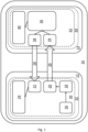
- FIG. 1 A first embodiment of a system 10 is illustrated schematically in Figure 1 .
- the system 10 comprises an aircraft 12 and a computing system 14 remote from the aircraft 12, also referred to as an off-board computing system 14.
- the aircraft 12 comprises an aircraft component 16, a sensor 18, a first transmitter 20, a first receiver 22 and a first indicator 24.
- the aircraft component 16 in some examples is a tire of a wheel of the aircraft 12, although other aircraft components, for example brakes or the like, are also envisaged as part of the system 10.
- the sensor 18 is a pressure sensor configured to monitor a pressure of the tire. It will be appreciated that the form the sensor 18 is largely dependent on the associated aircraft component 16, and that sensors other than pressure sensors are envisaged.
- the sensor 18 can also comprise a temperature sensor configured to directly and/or indirectly measure an internal gas temperature of the tire.
- sensor 18 can include one or more of, a tire temperature sensor, a brake temperature sensor, an oleo strut pressure sensor, an oleo strut temperature sensor, an oleo strut compression angle sensor, an oleo strut compression speed sensor, and an oleo strut compression distance sensor. Arrays of more than one sensor 18 per aircraft component are also envisaged.
- the first transmitter 20 is configured to communicate with the computing system 14, and in particular is configured to transmit sensor data 26 sensed by the sensor 18 to the computing system 14. Such transmission can occur in-flight of the aircraft 12, and/or when the aircraft 12 is on the ground.
- the first transmitter 20 can communicate wirelessly with the computing system 14 through any appropriate communications protocol, for example via a cellular, satellite and/or internet-based connection that enables long distance communication.
- the first transmitter 20 can communicate wirelessly with the computing system 14 via any of GateLink ® , WiFi ® , 4G, 5G, ACARS, or other satellite and/or cellular links.
- the first transmitter 20 and the sensor 18 can be integrated as part of a sensing device.
- the first receiver 22 is configured to communicate with the computing system 14, and in particular is configured to receive status data 28 from the computing system 14, as will be described in more detail hereafter. Such transmission can occur in-flight of the aircraft 12, and/or when the aircraft 12 is on the ground.
- the first receiver 22 can communicate wirelessly with the computing system 14 through any appropriate communications protocol, for example via a cellular, satellite and/ or internet-based connection that enables long distance communication.
- first transmitter 20 and first receiver 22 Although illustrated here separately as first transmitter 20 and first receiver 22, it will be appreciated that in practice the first transmitter and the first receiver 22 may be combined as a transceiver. It will further be appreciated that the aircraft 12 may comprise a plurality of transmitters, receivers, and/or transceivers in practice.
- the first indicator 24 is configured to be operable based on the status data 28 received by the first receiver 22 to provide an indication to aircraft crew.
- the first indicator 24 can take many forms, and in some examples can comprise one or more of a display, a light, and an audio emitter.
- the sensor 18, the first transmitter 20, the first receiver 22, and the first indicator are located within a first safety environment 30 on-board the aircraft 12, and are also located in a first data security environment 32 on-board the aircraft 12.
- the first safety environment 30 comprises a development assurance level (DAL) of DAL B.
- DAL may be defined as in Aerospace Recommended Practice ARP4754 from SAE International as of 19 January 2022.
- the first data security environment 32 comprises a security assurance level (SAL) of SAL 4.
- SAL may be defined as in Section 4.4 of document ED-203A produced by the European Organisation for Civil Aviation Equipment as of 19 January 2022.
- the computing system 14 comprises a second receiver 34, a processor 36, a second transmitter 38, and a second indicator 40. As mentioned above, the computing system 14 is located remotely from the aircraft 12, and in some examples may be located in an aircraft maintenance hub or the like.
- the second receiver 34 is configured to communicate with the aircraft 12, and in particular is configured to receive sensor data 26 from the aircraft 12, as will be described in more detail hereafter. Such transmission can occur in-flight of the aircraft 12, and/or when the aircraft 12 is on the ground.
- the second receiver 34 can communicate wirelessly with the aircraft 12 through any appropriate communications protocol, for example via a cellular, satellite and/or internet-based connection that enables long distance communication.
- the second receiver 34 is further configured to pass received sensor data 26 to the processor 36.
- the processor 36 comprises at least one processor that is configured to process received sensor data 26 to determine the status data 28 which is indicative of an operational mode of the aircraft component 16.
- the aircraft component 16 may comprise a normal operational mode in which the aircraft component 16 operates within normal or expected operating parameters, and one or more altered operational modes in which the aircraft component 16 operates outside the normal or expected operating parameters. Exemplary processing techniques to determine the operational mode are discussed in more detail hereinafter.
- the second transmitter 38 is configured to communicate with the aircraft 12, and in particular is configured to transmit status data 28 determined by the processor 36 to the aircraft 12. Such transmission can occur in-flight of the aircraft 12, and/or when the aircraft 12 is on the ground.
- the second transmitter 38 can communicate wirelessly with the aircraft through any appropriate communications protocol, for example via a cellular, satellite and/or internet-based connection that enables long distance communication.
- the second transmitter 38 can communicate wirelessly with the aircraft 12 via any of GateLink ® , WiFi ® , 4G, 5G, ACARS, or other satellite and/or cellular links.
- the second transmitter 38 is configured to transmit the status data 28 to the aircraft where the status data 28 is indicative of an altered operational mode of the aircraft component 16. In some examples, the second transmitter 38 is configured to transmit the status data 28 to the aircraft where the status data 28 is indicative of a normal operational mode of the aircraft component 16.
- the second indicator 40 is configured to be operable based on the status data 28 generated by the processor 36 to provide an indication to ground crew.
- the second indicator 40 can take many forms, and in some examples can comprise one or more of a display, a light, or an audio emitter.
- the second receiver 34, the processor 36, the second transmitter 38, and the second indicator 40 are located within a second safety environment 42, and are also located in a second data security environment 44.
- the second safety environment 42 comprises a development assurance level (DAL) of DAL B.
- the second data security environment 44 comprises a security assurance level (SAL) of SAL 4.
- the senor 18 is configured to obtain sensor data 26 related to the aircraft component 16.
- the aircraft component 16 comprises a tire
- the sensor 18 comprises a pressure sensor configured to monitor a pressure of the tire
- the pressure sensor can monitor a pressure of the tire when the aircraft 12 is either in-flight or on the ground, with the monitored pressure forming the sensor data 26.
- the sensor data 26 is then transmitted, via the first transmitter 20, from the aircraft 12 to the computing system 14, and in particular to the second receiver 34. As mentioned above, any appropriate communication protocol can be utilised for the transmission of the sensor data 26.
- the received sensor data 26 is passed from the second receiver 34 to the processor 36 of the computing system 14.
- the processor 36 can process the received sensor data 26 to generate status data 28 which is indicative of an operational mode of the aircraft 12. As mentioned above, the processing of the received sensor data 26 to generate the status data 28 can take several forms.
- the processing of the received sensor data 26 can take the form of a comparison between the received sensor data 26 to a reference or expected value.
- the sensor data 26 comprises pressure measurements associated with a tire of the aircraft
- the pressure measurements can be compared to a reference or expected pressure value to determine an operational mode of the tire, i.e. either a normal operational mode of the tire where the pressure matches or is within reference or expected tire pressure values for a given aircraft status, or an altered operational mode where the pressure does not match or is outside reference or expected tire pressure values for the given aircraft status.
- the processing of the received sensor data 26 can utilise a model of the aircraft 12, or an aircraft subsystem associated with the aircraft component 16, to determine an operational mode of the aircraft component 16, with the received sensor data 26 forming an input for the model.
- a model can comprise variables associated with a number of aircraft components, including the aircraft component 16, and connections between the variables. In some examples, such connections can take the form of equations or the like.
- the model can be determined via appropriate experimentation and/or simulation. It will be appreciated that the nature of the model will depend on the aircraft components and sensors utilised, and so particular model details are not provided herein, but will be apparent without undue limitation to a person skilled in the art. To provide more detailed modelling it will be appreciated that in some examples sensor data from a number of aircraft components may be transmitted via the first transmitter 20 to the processor 36 via the second receiver 34.
- the processing of the received sensor data 26 can utilise a machine learning model that takes the received sensor data 26 as an input and outputs an operational mode of the aircraft component 16 as an output.
- a number of sensor inputs associated with corresponding aircraft components may be utilised as inputs for such a machine learning model.
- the machine learning model can be trained using an appropriate training data set of sensor data parameters and ground truth labelled operational modes.
- the machine learning model can comprise a neural network or the like.
- the received sensor data 26 can be processed by the processor 36 to generate status data 28 which is indicative of an operational mode of the aircraft component 16.
- the status data 28 is transmitted from the computing system 14 to the aircraft 12, via the second transmitter 38 and the first receiver 22.
- the first indicator 24 can then indicate, based at least in part on the status data 28, the altered operational mode of the aircraft component 16 to aircraft crew.
- the altered operational mode can comprise a relatively high priority, and transmitting the status data 28 to the aircraft 12 in such examples can enable aircraft crew to be alerted to relatively high priority altered operational modes of the aircraft component 16 and take appropriate remedial action.
- aircraft crew can modify one or more operational parameters of the aircraft component 16 or other aircraft components to account for the altered operational mode of the aircraft component 16. For example, where the aircraft component 16 comprises a primary aircraft component, aircraft crew can revert to operation of a secondary aircraft component to perform the function previously provided by the primary aircraft component where an altered operational mode of the primary aircraft component has been indicated.
- aircraft crew can schedule a maintenance action, e.g. a future maintenance action, for the aircraft component 16 based on the indication by the first indicator 24.
- a maintenance action e.g. a future maintenance action
- the second indicator 40 can alternatively or additionally provide an indication of the altered operational mode of the aircraft component 16 to ground crew. Ground crew can then take appropriate remedial action, for example by scheduling a maintenance action to be performed on the aircraft component 16 to revert the aircraft component 16 to a normal operational mode.
- the computing system 14 can automatically schedule a maintenance action for the aircraft component 16 based at least in part on the status data 28 indicative of an altered operational mode of the aircraft component 16 and/or based at least in part on the indication provided by the second indicator 40.
- relatively high priority altered operational modes of the aircraft component 16 can comprise current altered operational modes of the aircraft component 16, for example operational modes that require imminent or immediate remedial action to correct.
- relatively low priority altered operational modes of the aircraft component 16 can comprise future altered operational modes of the aircraft component 16, for example operational modes that may require future remedial action to correct.
- sensor data 26 from the sensor 18 is processed by the off-board computing system 14 to generate status data 28 which indicates an altered operational mode of the aircraft component 16.
- the status data 28 is transmitted to the aircraft 12, with an indication provided by the first indicator 24 which can enable aircraft crew to take appropriate remedial action.
- use of sensors that do not need to integrate or interface with existing on-board avionics may be enabled. This may enable new sensors with additional, improved and/or alternative functionality to existing sensors to be added to an aircraft in a relatively cost-effective and efficient manner, with minimal impact at an aircraft level.
- the senor 18, the first transmitter 20, the first receiver 22, and the first indicator are located within a first safety environment 30 of DAL B on-board the aircraft 12, and are also located in a first data security environment 32 of SAL 4 on-board the aircraft 12.
- the second receiver 34, the processor 36, the second transmitter 38, and the second indicator 40 are located within a second safety environment 42 of DAL B, and are also located in a second data security environment 44 of SAL 4.
- the DAL of the first 30 and second 42 safety environments are the same, and SAL of the first data security environment 32 and the second data security environment 42 are the same.
- Maintaining a relatively high DAL and SAL level both at the aircraft 12 and the computing system 14 may facilitate transfer of sensor data 26 and status data 28 between the aircraft 12 and the computing system 14, and provide an assurance of the operation at the computing system 14.
- the sensor data 26 and status data 28 may also be encrypted via an appropriate security mechanism.
- a plurality of aircraft components 16 and a number of sensors 18 can be provided, with sensor data from each sensor 18 being transmitted from the aircraft 12 to the computer system 14 via one or more transmitters, before being processed by the processor 36 to generate status data indicative of an operational mode of one or more of the aircraft components 16.
- An aircraft component 16 mentioned above is a tire, with a corresponding sensor 18 being a tire pressure sensor.
- Other aircraft components can include brakes or the like, with other sensors 18 including brake wear sensors and/or tire tread sensors.
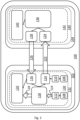
- FIG. 2 A second embodiment of a system 100 is illustrated schematically in Figure 2 . Some components of the system 100 of Figure 2 are substantially similar to those of Figure 1 .
- the system 100 of Figure 2 comprises an aircraft 102 and a computing system 104 remote from the aircraft 102, also referred to as an off-board computing system 104.
- the aircraft 102 comprises a first aircraft component 106, a second aircraft component 108, a first sensor 110, a second sensor 112, a first transmitter 114, a first receiver 116, processing avionics 118 and a first indicator 120.
- the first aircraft component 106 comprises a relatively low priority aircraft component, for example an aircraft component which is deemed noncritical to operation of the aircraft 102 if it were to operate in an altered operational mode, such as outside normal or expected operational parameters.
- the second aircraft component 108 comprises a relatively high priority aircraft component, for example an aircraft component which is deemed critical to operation of the aircraft 102 if it were to operate in an altered operational mode, such as outside normal or expected operational parameters.
- the first sensor 110 is associated with the first aircraft component 106, and is configured to sense one or more parameters associated with the first aircraft component 106 to provide first sensor data 122.
- the second sensor 112 is associated with the second aircraft component 108, and is configured to sense one or more parameters associated with the second aircraft component 108 to provide second sensor data 124.
- the first transmitter 114 is configured to communicate with the computing system 104, and in particular is configured to transmit the first sensor data 122 sensed by the first sensor 110 to the computing system 104. Such transmission can occur in-flight of the aircraft 102, and/or when the aircraft 102 is on the ground.
- the first transmitter 114 can communicate wirelessly with the computing system 104 through any appropriate communications protocol, for example via a cellular, satellite and/or internet-based connection that enables long distance communication.
- the first transmitter 114 and the first sensor 110 can be integrated as part of a sensing device.
- the first receiver 116 is configured to communicate with the computing system 140, and in particular is configured to receive first status data 126 from the computing system 104, as will be described in more detail hereafter. Such transmission can occur in-flight of the aircraft 102, and/or when the aircraft 102 is on the ground.
- the first receiver 116 can communicate wirelessly with the computing system 104 through any appropriate communications protocol, for example via a cellular, satellite and/or internet-based connection that enables long distance communication.
- first transmitter 114 and first receiver 116 may be combined as a transceiver. It will further be appreciated that the aircraft 102 may comprise a number of transmitters, receivers, or transceivers in practice.
- the processing avionics 118 comprises one or more processors which are configured to process received second sensor data 124 to determine second status data 128 which is indicative of an operational mode of the second aircraft component 108.
- the second aircraft component 108 may comprise a normal operational mode in which the second aircraft component 108 operates within normal or expected operating parameters, and one or more altered operational modes in which the second aircraft component 108 operates outside the normal or expected operating parameters.
- Exemplary processing techniques to determine the operational mode can, in some examples, be similar to those discussed above in relation to the processor 36 of the computing system 14 of the system 10 of Figure 1 .
- the processing avionics 118 can send the second status data 128 to the computing system 104 for further processing via the first transmitter 114, and/or can receive the first status data 126 for further processing from the computing system 104 via the first receiver 116.
- the first indicator 120 is configured to be operable based on the first status data 126 and/or the second status data 128 to provide an indication to aircraft crew.
- the first indicator 120 can take many forms, and in some examples can comprise one or more of a display, a light, or an audio emitter. It will be appreciated that there may be a number of first indicators in practice, and indeed in some examples there may be a first indicator corresponding to each of the first 106 and second 108 aircraft components.
- the first sensor 110, the second sensor 112, the first transmitter 114, the first receiver 116, the processing avionics 118 and the first indicator 120 are located within a first safety environment 130 on-board the aircraft 102, and are also located in a first data security environment 132 on-board the aircraft 102.
- the first safety environment 130 comprises a development assurance level (DAL) of DAL B.
- the first data security environment 132 comprises a security assurance level (SAL) of SAL 4.
- the computing system 104 comprises a second receiver 134, a processor 136, a second transmitter 138, and a second indicator 140.
- the computing system 104 is located remotely from the aircraft 102, and in some examples may be located in an aircraft maintenance hub or the like.
- the second receiver 134 is configured to communicate with the aircraft 102, and in particular is configured to receive the first sensor data 122 from the aircraft 102, as will be described in more detail hereafter. Such transmission can occur in-flight of the aircraft 102, and/or when the aircraft 102 is on the ground.
- the second receiver 134 can communicate wirelessly with the aircraft 102 through any appropriate communications protocol, for example via a cellular, satellite and/or internet-based connection that enables long distance communication.
- the second receiver 134 is further configured to pass received first sensor data 122 to the processor 136.
- the processor 136 comprises at least one processor that is configured to process received first sensor data 122 to determine the first status data 126 which is indicative of an operational mode of the first aircraft component 106.
- the first aircraft component 106 may comprise a normal operational mode in which the first aircraft component 106 operates within normal or expected operating parameters, and one or more altered operational modes in which the first aircraft component 106 operates outside the normal or expected operating parameters.
- Exemplary processing techniques to determine the operational mode can, in some examples, be similar to those discussed above in relation to the processor 36 of the computing system 14 of the system 10 of Figure 1 .
- the second transmitter 138 is configured to communicate with the aircraft 102, and in particular is configured to transmit the first status data 126 determined by the processor 136 to the aircraft 102. Such transmission can occur in-flight of the aircraft 102, and/or when the aircraft 102 is on the ground.
- the second transmitter 138 can communicate wirelessly with the aircraft through any appropriate communications protocol, for example via a cellular, satellite and/or internet-based connection that enables long distance communication.
- the second transmitter 138 is configured to transmit the first status data 126 to the aircraft where the first status data 126 is indicative of an altered operational mode of the first aircraft component 106. In some examples, the second transmitter 138 is configured to transmit the first status data 126 to the aircraft 102 where the first status data 126 is indicative of a normal operational mode of the first aircraft component 106.
- the second indicator 140 is configured to be operable based on the first status data 126 generated by the processor 136 to provide an indication to ground crew.
- the second indicator 140 can take many forms, and in some examples can comprise one or more of a display, a light, or an audio emitter.
- second status data 128 can be received by the computing system from the processing avionics 118 of the aircraft 102.
- the second indicator 140 is configured to be operable based on the second status data 128 generated by the processing avionics 128 to provide an indication to ground crew.
- the second receiver 134, the processor 136, the second transmitter 138, and the second indicator 140 are located within a second safety environment 142, and are also located in a second data security environment 144.
- the second safety environment 142 comprises a development assurance level (DAL) lower than that of the first safety environment 130 on-board the aircraft 102.
- the second safety environment 142 comprises a DAL of DAL C or DAL E.
- the second data security environment 144 comprises a security assurance level (SAL)) lower than that of the first data security environment 132 on-board the aircraft 102.
- the second data security environment 144 comprises a SAL of SAL 3 or lower.
- a lower DAL and/or SAL level in the computing system 104 may be useful by reducing the certification requirements of the computing system 104, a high assurance environment is still provided in the aircraft including the processing avionics 118.
- Such a difference between the first 130 and second 142 safety environments and/or between the first 132 and second 144 data security environments may be facilitated by encryption and decryption of data, such as the first sensor data 122 and the first status data 126, prior to and post transmission of such data between the aircraft 102 and the computing system 104.
- data such as the first sensor data 122 and the first status data 126
- many encryption/decryption protocols may be suitable, and so details of such encryption/decryption is not provided here for the sake of brevity, but will be immediately apparent to a person skilled in the art without undue limitation.
- the first sensor 110 is configured to obtain first sensor data 122 related to the first aircraft component 106
- the second sensor 112 is configured to obtain second sensor data 124 related to the second aircraft component 108.
- the first aircraft component 106 can comprise a relatively low priority aircraft component
- the second aircraft component 108 can comprise a relatively high priority aircraft component.
- the first sensor data 122 can comprise relatively low priority sensor data
- the second sensor data 124 can comprise relatively high priority sensor data.
- first sensor data 122 For relatively low priority sensor data, such as the first sensor data 122, latency in data processing and/or interruptions in providing the data may be considered to be acceptable in certain circumstances. This may enable the first sensor data 122 to be transmitted, via the first transmitter 114, from the aircraft 102 to the computing system 104, and in particular to the second receiver 134. The received first sensor data 122 can then be processed by the processor 136 in a similar manner to that described above in relation to the processor 36 of the computing system 14 of the first embodiment of the system 10, to generate the first status data 126 which is indicative of an operational mode of the first aircraft component 106.
- the first status data 126 is indicative of an altered operational mode of the first aircraft component 106
- the first status data is transmitted from the computing system 104 to the aircraft 102, via the second transmitter 138 and the first receiver 116.
- the first indicator 120 can then indicate, based at least in part on the first status data 126, the altered operational mode of the first aircraft component 106 to aircraft crew. As mentioned in relation to the system 10 of the first embodiment of Figure 1 , aircraft crew can then take appropriate remedial action based on the indication of the altered operational mode of the first aircraft component 106, for example by scheduling an appropriate maintenance action.
- the second indicator 140 can alternatively or additionally provide an indication of the altered operational mode of the first aircraft component 106 to ground crew. Ground crew can then take appropriate remedial action, for example by scheduling a maintenance action to be performed on the first aircraft component 106 to revert the aircraft component 106 to a normal operational mode.
- latency in data processing and/or interruptions in providing the data may be considered to be unacceptable, for example where an altered operational state of the second aircraft component 108 is deemed to be critical to operation of the aircraft 102.
- the second sensor data 124 is processed using the on-board processing avionics 118 to generate the second status data 128 indicative of an operational mode of the second aircraft component 108.
- the first indicator 120 can then indicate, based at least in part on the second status data 128, an altered operational mode of the second aircraft component 108 to aircraft crew.
- aircraft crew can then take appropriate remedial action based on the indication of the altered operational mode of the first aircraft component 106. Such action can include, for example, aircraft crew reverting to operation of a further aircraft component to perform the function previously provided by the second aircraft component, or scheduling an appropriate maintenance action to take place.
- the second embodiment of the system 100 of Figure 2 may also enable use of sensors that do not need to integrate with existing on-board avionics, which may enable new sensors with additional and/or alternative functionality to existing sensors to be added to an aircraft in a relatively cost-effective and efficient manner, with minimal impact at an aircraft level.
- the system 100 of Figure 2 also ensures that, for relatively high priority data and/or components, processing can remain on-board via the processing avionics 118, which may ensure data continuity, and reduce latency.
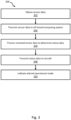
- a method 200 in accordance with the first 10 and second 100 embodiments of the system is illustrated in the flow diagram of Figure 3 .
- the method 200 comprises obtaining 202, via a sensor on-board an aircraft, sensor data associated with an aircraft component of the aircraft.
- the method 200 comprises transmitting 204 the sensor data to an off-board computing system.
- the method 200 comprises processing 206, via one or more processors of the off-board computing system, the received sensor data to determine status data indicative of an operational mode of the aircraft component.
- the method 200 comprises transmitting 208, from the off-board computing system to the aircraft, and when the status data is indicative of an altered operational mode of the aircraft, the status data.
- the method comprises indicating 210, by the aircraft, the altered operational mode of the aircraft component.
- the method 200 may enable use of sensors that do not need to integrate with existing on-board avionics, which may enable new sensors with additional and/or alternative functionality to existing sensors to be added to an aircraft in a relatively cost-effective and efficient manner, with minimal impact at an aircraft level.
- aircraft components associated with the undercarriage such as tires and brakes
- aircraft components associated with the undercarriage include fuel tanks and associated fuel level sensors and/or fuel composition sensors.
- aircraft components associated with the undercarriage, and associated sensors include a landing gear extension/retraction mechanism, such as an oleo strut, and associated sensors such as an oleo strut pressure sensor, an oleo strut temperature sensor, an oleo strut compression angle sensor, an oleo strut compression speed sensor, and an oleo strut compression distance sensor.
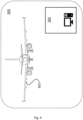
- FIG. 4 An exemplary system 300 in which the first 10 and second 100 embodiments can be practiced is illustrated in Figure 4 , which shows an aircraft 302 and a computing system 304.
- the computing system 304 is off-board of the aircraft 302, e.g. remote from the aircraft 302.
Landscapes
- Engineering & Computer Science (AREA)
- Aviation & Aerospace Engineering (AREA)
- Physics & Mathematics (AREA)
- General Physics & Mathematics (AREA)
- Transportation (AREA)
- Manufacturing & Machinery (AREA)
- Mechanical Engineering (AREA)
- Computer Networks & Wireless Communication (AREA)
- Signal Processing (AREA)
- Artificial Intelligence (AREA)
- Evolutionary Computation (AREA)
- Mathematical Physics (AREA)
- Automation & Control Theory (AREA)
- Arrangements For Transmission Of Measured Signals (AREA)
Abstract
Description
- The present invention relates to a system including an aircraft and a computing system remote from the aircraft.
- Aircraft typically comprise many sensors to monitor the state of associated aircraft components, with the sensor data either provided directly to aircraft crew, or processed and provided to aircraft crew, to provide an indication as to the state of the aircraft components. Aircraft crew can then take appropriate action based on the state of the aircraft components.
- A first aspect of the present invention provides a system comprising: an aircraft comprising a sensor, an aircraft component associated with the sensor, a first transmitter, and a first receiver; and a computing system remote from the aircraft, the computing system comprising one or more processors, a second transmitter, and a second receiver: wherein: the aircraft is configured to transmit, via the first transmitter, sensor data sensed by the sensor, to the computing system; the computing system is configured to: receive, via the second receiver, sensor data transmitted from the aircraft; process, using the one or more processors, the received sensor data to generate status data indicative of an operational mode of the aircraft component; transmit, when the status data is indicative of an altered operational mode of the aircraft component, the status data to the aircraft via the second transmitter; and the aircraft is configured to indicate, based at least partially on the status data received by the first receiver, the altered operational mode of the aircraft component.
- Optionally, the aircraft is configured to indicate, based at least in part on the status data, a further altered operational mode of the aircraft component, the further altered operational mode comprising a lower priority than the altered operational mode.
- Optionally, the computing system is configured to indicate, based at least in part on the status data, a further altered operational mode of the aircraft component, the further altered operational mode comprising a lower priority than the altered operational mode.
- Optionally, the sensor, the first transmitter, and the first receiver are located in a first safety environment on-board the aircraft, the first safety environment comprising a first development assurance level, and the second transmitter, the second receiver, and the one or more processors are located in a second safety environment of the computing system, the second safety environment comprising a second development assurance level the same as the first development assurance level.
- Optionally, the sensor, the first transmitter and the first receiver, are located in a first data security environment on-board the aircraft, the first data security environment comprising a first security assurance level, and the second transmitter, the second receiver, and the one or more processors are located in a second data security environment of the computing system, the second data security environment comprising a second security assurance level the same as the first security assurance level.
- Optionally, the sensor, the first transmitter, and the first receiver are located in a first safety environment on-board the aircraft, the first safety environment comprising a first development assurance level, and the second transmitter, the second receiver, and the one or more processors are located in a second safety environment of the computing system, the second safety environment comprising a second development assurance level different to the first development assurance level.
- Optionally, the second development assurance level is lower than the first development assurance level.
- Optionally, the first transmitter and the first receiver are located in a first data security environment on-board the aircraft, the first data security environment comprising a first security assurance level, and the second transmitter, the second receiver, and the one or more processors are located in a second data security environment of the computing system, the second data security environment comprising a second security assurance level different to the first security assurance level.
- Optionally, the second security assurance level is lower than the first security assurance level.
- Optionally, the aircraft is configured to encrypt the sensor data prior to transmitting the sensor data to the off-board computing system via the first transmitter; and the computing system is configured to decrypt, via the one or more processors of the computing system the sensor data received by the second receiver.
- Optionally, the aircraft comprises one or more on-board processors configured to process sensor data of the aircraft component to obtain on-board status data indicative of a operational mode of the aircraft component associated with the sensor, and the aircraft is configured to, based at least in part on the on-board status data, and when the on-board status data is indicative of an altered operational mode of the aircraft component, indicate the altered operational mode of the aircraft component.
- Optionally, the aircraft comprises a plurality of sensors each sensor configured to obtain respective sensor data associated with the aircraft component; the aircraft is configured to transmit, via the first transmitter, sensor data from each of the plurality of sensors to the computing system; the computing system is configured to receive, via the second receiver, the transmitted sensor data from each of the plurality of sensors; and the computing system is configured to process, via the one or more processors of the computing system, the received sensor data from each of the plurality of sensors to determine the status data indicative of the altered operational mode of the aircraft component.
- Optionally, the sensor comprises at least one of a tire pressure monitoring sensor, a brake wear sensor, a tire tread sensor, a tire temperature sensor, a brake temperature sensor, an oleo strut pressure sensor, an oleo strut temperature sensor, an oleo strut compression angle sensor, an oleo strut compression speed sensor, and an oleo strut compression distance sensor.
- A second aspect of the present invention provides an aircraft comprising a sensor, an aircraft component associated with the sensor, a transmitter, and a receiver, wherein the aircraft is configured to: transmit sensor data from the sensor, via the first transmitter, to a computing system remote from the aircraft; receive, from the computing system and via the receiver, status data derived from the sensor data by one or more processors of the computing system, the status data indicative of an altered operational mode of the aircraft component; and indicate, based at least partially on the status data received by the first receiver, the altered operational mode of the aircraft component.
- A third aspect of the present invention provides an off-board computing system comprising one or more processors, a transmitter, and a receiver, wherein the off-board computing system is configured to: receive, via the receiver, sensor data from an aircraft, the sensor data associated with an aircraft component of the aircraft; process, using the one or more processors, the received sensor data to generate status data indicative of an operational mode of the aircraft component; and transmit, when the status data is indicative of an altered operational mode of the aircraft component and via the transmitter, the status data to the aircraft.
- A fourth aspect of the present invention provides a method comprising: obtaining, via a sensor on-board an aircraft, sensor data associated with an aircraft component of the aircraft; transmitting the sensor data to an off-board computing system; processing, via one or more processors of the off-board computing system, the received sensor data to determine status data indicative of an operational mode of the aircraft component; transmitting, from the off-board computing system to the aircraft, and when the status data is indicative of an altered operational mode of the aircraft, the status data; and indicating, by the aircraft, the altered operational mode of the aircraft component.
- Optionally, the method comprises scheduling, based at least in part on the status data, a maintenance action to be performed on the aircraft component.
- Optionally, the method comprises processing, via one or more processors of the off-board computing system, the received sensor data to determine further status data indicative of a further operational mode of the aircraft component, and indicating, where the further operational mode of the aircraft component comprises a further altered operational mode of the aircraft component, and at the off-board computing system, the further altered operational mode of the aircraft component.
- Optionally, the method comprises scheduling, based at least in part on the further status data, a further maintenance action to be performed on the aircraft component.
- A fifth aspect of the present invention provides a system comprising: an aircraft comprising an on-board sensor, and an aircraft component associated with the sensor; and an off-board computing system: wherein the off-board computing system is configured to: receive sensor data transmitted from the aircraft; process the received sensor data to determine an altered operational mode of the aircraft component; and transmit a message indicative of the altered operational mode of the aircraft component to the aircraft; and the aircraft is configured to indicate, based at least in part on the message, the altered operational mode of the aircraft component.
- Embodiments of the invention will now be described, by way of example only, with reference to the accompanying drawings, in which:
-
Figure 1 shows a schematic view of a first embodiment of a system comprising an aircraft and a remote computing system; -
Figure 2 shows a schematic view of a second embodiment of a system comprising an aircraft and a remote computing system; -
Figure 3 shows a flow diagram of a method in accordance with the systems ofFigures 1 and2 ; and -
Figure 4 shows a schematic view of an example system in which the first and second embodiments can be practiced - A first embodiment of a
system 10 is illustrated schematically inFigure 1 . Thesystem 10 comprises anaircraft 12 and acomputing system 14 remote from theaircraft 12, also referred to as an off-board computing system 14. - The
aircraft 12 comprises anaircraft component 16, asensor 18, a first transmitter 20, afirst receiver 22 and afirst indicator 24. - The
aircraft component 16 in some examples is a tire of a wheel of theaircraft 12, although other aircraft components, for example brakes or the like, are also envisaged as part of thesystem 10. In some examples thesensor 18 is a pressure sensor configured to monitor a pressure of the tire. It will be appreciated that the form thesensor 18 is largely dependent on the associatedaircraft component 16, and that sensors other than pressure sensors are envisaged. For example, thesensor 18 can also comprise a temperature sensor configured to directly and/or indirectly measure an internal gas temperature of the tire. Other forms ofsensor 18 can include one or more of, a tire temperature sensor, a brake temperature sensor, an oleo strut pressure sensor, an oleo strut temperature sensor, an oleo strut compression angle sensor, an oleo strut compression speed sensor, and an oleo strut compression distance sensor. Arrays of more than onesensor 18 per aircraft component are also envisaged. - The first transmitter 20 is configured to communicate with the
computing system 14, and in particular is configured to transmitsensor data 26 sensed by thesensor 18 to thecomputing system 14. Such transmission can occur in-flight of theaircraft 12, and/or when theaircraft 12 is on the ground. The first transmitter 20 can communicate wirelessly with thecomputing system 14 through any appropriate communications protocol, for example via a cellular, satellite and/or internet-based connection that enables long distance communication. In some examples the first transmitter 20 can communicate wirelessly with thecomputing system 14 via any of GateLink®, WiFi®, 4G, 5G, ACARS, or other satellite and/or cellular links. In some examples, the first transmitter 20 and thesensor 18 can be integrated as part of a sensing device. - The
first receiver 22 is configured to communicate with thecomputing system 14, and in particular is configured to receivestatus data 28 from thecomputing system 14, as will be described in more detail hereafter. Such transmission can occur in-flight of theaircraft 12, and/or when theaircraft 12 is on the ground. Thefirst receiver 22 can communicate wirelessly with thecomputing system 14 through any appropriate communications protocol, for example via a cellular, satellite and/ or internet-based connection that enables long distance communication. - Although illustrated here separately as first transmitter 20 and
first receiver 22, it will be appreciated that in practice the first transmitter and thefirst receiver 22 may be combined as a transceiver. It will further be appreciated that theaircraft 12 may comprise a plurality of transmitters, receivers, and/or transceivers in practice. - The
first indicator 24 is configured to be operable based on thestatus data 28 received by thefirst receiver 22 to provide an indication to aircraft crew. Thefirst indicator 24 can take many forms, and in some examples can comprise one or more of a display, a light, and an audio emitter. - The
sensor 18, the first transmitter 20, thefirst receiver 22, and the first indicator are located within afirst safety environment 30 on-board theaircraft 12, and are also located in a firstdata security environment 32 on-board theaircraft 12. In some examples thefirst safety environment 30 comprises a development assurance level (DAL) of DAL B. DAL may be defined as in Aerospace Recommended Practice ARP4754 from SAE International as of 19 January 2022. In some examples, the firstdata security environment 32 comprises a security assurance level (SAL) of SAL 4. SAL may be defined as in Section 4.4 of document ED-203A produced by the European Organisation for Civil Aviation Equipment as of 19 January 2022. - The
computing system 14 comprises asecond receiver 34, aprocessor 36, a second transmitter 38, and asecond indicator 40. As mentioned above, thecomputing system 14 is located remotely from theaircraft 12, and in some examples may be located in an aircraft maintenance hub or the like. - The
second receiver 34 is configured to communicate with theaircraft 12, and in particular is configured to receivesensor data 26 from theaircraft 12, as will be described in more detail hereafter. Such transmission can occur in-flight of theaircraft 12, and/or when theaircraft 12 is on the ground. Thesecond receiver 34 can communicate wirelessly with theaircraft 12 through any appropriate communications protocol, for example via a cellular, satellite and/or internet-based connection that enables long distance communication. Thesecond receiver 34 is further configured to pass receivedsensor data 26 to theprocessor 36. - The
processor 36 comprises at least one processor that is configured to process receivedsensor data 26 to determine thestatus data 28 which is indicative of an operational mode of theaircraft component 16. For example, theaircraft component 16 may comprise a normal operational mode in which theaircraft component 16 operates within normal or expected operating parameters, and one or more altered operational modes in which theaircraft component 16 operates outside the normal or expected operating parameters. Exemplary processing techniques to determine the operational mode are discussed in more detail hereinafter. - The second transmitter 38 is configured to communicate with the
aircraft 12, and in particular is configured to transmitstatus data 28 determined by theprocessor 36 to theaircraft 12. Such transmission can occur in-flight of theaircraft 12, and/or when theaircraft 12 is on the ground. The second transmitter 38 can communicate wirelessly with the aircraft through any appropriate communications protocol, for example via a cellular, satellite and/or internet-based connection that enables long distance communication. In some examples the second transmitter 38 can communicate wirelessly with theaircraft 12 via any of GateLink®, WiFi®, 4G, 5G, ACARS, or other satellite and/or cellular links. - In some examples, the second transmitter 38 is configured to transmit the
status data 28 to the aircraft where thestatus data 28 is indicative of an altered operational mode of theaircraft component 16. In some examples, the second transmitter 38 is configured to transmit thestatus data 28 to the aircraft where thestatus data 28 is indicative of a normal operational mode of theaircraft component 16. - The
second indicator 40 is configured to be operable based on thestatus data 28 generated by theprocessor 36 to provide an indication to ground crew. Thesecond indicator 40 can take many forms, and in some examples can comprise one or more of a display, a light, or an audio emitter. - The
second receiver 34, theprocessor 36, the second transmitter 38, and thesecond indicator 40 are located within asecond safety environment 42, and are also located in a seconddata security environment 44. In some examples thesecond safety environment 42 comprises a development assurance level (DAL) of DAL B. In some examples, the seconddata security environment 44 comprises a security assurance level (SAL) of SAL 4. - In use, the
sensor 18 is configured to obtainsensor data 26 related to theaircraft component 16. For example, where theaircraft component 16 comprises a tire, and thesensor 18 comprises a pressure sensor configured to monitor a pressure of the tire, the pressure sensor can monitor a pressure of the tire when theaircraft 12 is either in-flight or on the ground, with the monitored pressure forming thesensor data 26. - The
sensor data 26 is then transmitted, via the first transmitter 20, from theaircraft 12 to thecomputing system 14, and in particular to thesecond receiver 34. As mentioned above, any appropriate communication protocol can be utilised for the transmission of thesensor data 26. The receivedsensor data 26 is passed from thesecond receiver 34 to theprocessor 36 of thecomputing system 14. - The
processor 36 can process the receivedsensor data 26 to generatestatus data 28 which is indicative of an operational mode of theaircraft 12. As mentioned above, the processing of the receivedsensor data 26 to generate thestatus data 28 can take several forms. - As one example, the processing of the received
sensor data 26 can take the form of a comparison between the receivedsensor data 26 to a reference or expected value. For example, where thesensor data 26 comprises pressure measurements associated with a tire of the aircraft, the pressure measurements can be compared to a reference or expected pressure value to determine an operational mode of the tire, i.e. either a normal operational mode of the tire where the pressure matches or is within reference or expected tire pressure values for a given aircraft status, or an altered operational mode where the pressure does not match or is outside reference or expected tire pressure values for the given aircraft status. - As another example, the processing of the received
sensor data 26 can utilise a model of theaircraft 12, or an aircraft subsystem associated with theaircraft component 16, to determine an operational mode of theaircraft component 16, with the receivedsensor data 26 forming an input for the model. Such a model can comprise variables associated with a number of aircraft components, including theaircraft component 16, and connections between the variables. In some examples, such connections can take the form of equations or the like. The model can be determined via appropriate experimentation and/or simulation. It will be appreciated that the nature of the model will depend on the aircraft components and sensors utilised, and so particular model details are not provided herein, but will be apparent without undue limitation to a person skilled in the art. To provide more detailed modelling it will be appreciated that in some examples sensor data from a number of aircraft components may be transmitted via the first transmitter 20 to theprocessor 36 via thesecond receiver 34. - As another example, the processing of the received
sensor data 26 can utilise a machine learning model that takes the receivedsensor data 26 as an input and outputs an operational mode of theaircraft component 16 as an output. As with the model of theaircraft 12 or the aircraft subsystem discussed above, a number of sensor inputs associated with corresponding aircraft components may be utilised as inputs for such a machine learning model. The machine learning model can be trained using an appropriate training data set of sensor data parameters and ground truth labelled operational modes. In some examples, the machine learning model can comprise a neural network or the like. - In each of the examples mentioned above, the received
sensor data 26 can be processed by theprocessor 36 to generatestatus data 28 which is indicative of an operational mode of theaircraft component 16. Where thestatus data 28 is indicative of an altered operational mode of theaircraft component 16, thestatus data 28 is transmitted from thecomputing system 14 to theaircraft 12, via the second transmitter 38 and thefirst receiver 22. - The
first indicator 24 can then indicate, based at least in part on thestatus data 28, the altered operational mode of theaircraft component 16 to aircraft crew. In some examples the altered operational mode can comprise a relatively high priority, and transmitting thestatus data 28 to theaircraft 12 in such examples can enable aircraft crew to be alerted to relatively high priority altered operational modes of theaircraft component 16 and take appropriate remedial action. In some examples, aircraft crew can modify one or more operational parameters of theaircraft component 16 or other aircraft components to account for the altered operational mode of theaircraft component 16. For example, where theaircraft component 16 comprises a primary aircraft component, aircraft crew can revert to operation of a secondary aircraft component to perform the function previously provided by the primary aircraft component where an altered operational mode of the primary aircraft component has been indicated. - In some examples, such as where the altered operational mode of the
aircraft component 16 is of a relatively low priority, aircraft crew can schedule a maintenance action, e.g. a future maintenance action, for theaircraft component 16 based on the indication by thefirst indicator 24. - In some examples, where the
status data 28 is indicative of a relatively low priority altered operational mode of theaircraft component 16, thesecond indicator 40 can alternatively or additionally provide an indication of the altered operational mode of theaircraft component 16 to ground crew. Ground crew can then take appropriate remedial action, for example by scheduling a maintenance action to be performed on theaircraft component 16 to revert theaircraft component 16 to a normal operational mode. - In some examples, the
computing system 14 can automatically schedule a maintenance action for theaircraft component 16 based at least in part on thestatus data 28 indicative of an altered operational mode of theaircraft component 16 and/or based at least in part on the indication provided by thesecond indicator 40. - In some examples, relatively high priority altered operational modes of the
aircraft component 16 can comprise current altered operational modes of theaircraft component 16, for example operational modes that require imminent or immediate remedial action to correct. In some examples, relatively low priority altered operational modes of theaircraft component 16 can comprise future altered operational modes of theaircraft component 16, for example operational modes that may require future remedial action to correct. - In the manner described above,
sensor data 26 from thesensor 18 is processed by the off-board computing system 14 to generatestatus data 28 which indicates an altered operational mode of theaircraft component 16. Thestatus data 28 is transmitted to theaircraft 12, with an indication provided by thefirst indicator 24 which can enable aircraft crew to take appropriate remedial action. By conducting processing of thesensor data 26 using the off-board computing system 14, use of sensors that do not need to integrate or interface with existing on-board avionics may be enabled. This may enable new sensors with additional, improved and/or alternative functionality to existing sensors to be added to an aircraft in a relatively cost-effective and efficient manner, with minimal impact at an aircraft level. Given that the processing takes place at the off-board computing system 14, increased flexibility and ease of updating of the off-board computing system may be provided relative to having to update existing on-board avionics. By reducing the need for on-board avionics, aircraft weight and cost may be reduced. - As illustrated in the embodiment of
Figure 1 and as discussed above, thesensor 18, the first transmitter 20, thefirst receiver 22, and the first indicator are located within afirst safety environment 30 of DAL B on-board theaircraft 12, and are also located in a firstdata security environment 32 of SAL 4 on-board theaircraft 12. Thesecond receiver 34, theprocessor 36, the second transmitter 38, and thesecond indicator 40 are located within asecond safety environment 42 of DAL B, and are also located in a seconddata security environment 44 of SAL 4. Here the DAL of the first 30 and second 42 safety environments are the same, and SAL of the firstdata security environment 32 and the seconddata security environment 42 are the same. Maintaining a relatively high DAL and SAL level both at theaircraft 12 and thecomputing system 14 may facilitate transfer ofsensor data 26 andstatus data 28 between theaircraft 12 and thecomputing system 14, and provide an assurance of the operation at thecomputing system 14. Thesensor data 26 andstatus data 28 may also be encrypted via an appropriate security mechanism. - As mentioned briefly above, in some examples a plurality of
aircraft components 16 and a number ofsensors 18 can be provided, with sensor data from eachsensor 18 being transmitted from theaircraft 12 to thecomputer system 14 via one or more transmitters, before being processed by theprocessor 36 to generate status data indicative of an operational mode of one or more of theaircraft components 16. One example of anaircraft component 16 mentioned above is a tire, with a correspondingsensor 18 being a tire pressure sensor. Other aircraft components can include brakes or the like, withother sensors 18 including brake wear sensors and/or tire tread sensors. - A second embodiment of a
system 100 is illustrated schematically inFigure 2 . Some components of thesystem 100 ofFigure 2 are substantially similar to those ofFigure 1 . - The
system 100 ofFigure 2 comprises anaircraft 102 and acomputing system 104 remote from theaircraft 102, also referred to as an off-board computing system 104. - The
aircraft 102 comprises afirst aircraft component 106, asecond aircraft component 108, afirst sensor 110, asecond sensor 112, afirst transmitter 114, afirst receiver 116,processing avionics 118 and afirst indicator 120. - In some examples, the
first aircraft component 106 comprises a relatively low priority aircraft component, for example an aircraft component which is deemed noncritical to operation of theaircraft 102 if it were to operate in an altered operational mode, such as outside normal or expected operational parameters. In some examples, thesecond aircraft component 108 comprises a relatively high priority aircraft component, for example an aircraft component which is deemed critical to operation of theaircraft 102 if it were to operate in an altered operational mode, such as outside normal or expected operational parameters. - The
first sensor 110 is associated with thefirst aircraft component 106, and is configured to sense one or more parameters associated with thefirst aircraft component 106 to providefirst sensor data 122. Thesecond sensor 112 is associated with thesecond aircraft component 108, and is configured to sense one or more parameters associated with thesecond aircraft component 108 to providesecond sensor data 124. - The
first transmitter 114 is configured to communicate with thecomputing system 104, and in particular is configured to transmit thefirst sensor data 122 sensed by thefirst sensor 110 to thecomputing system 104. Such transmission can occur in-flight of theaircraft 102, and/or when theaircraft 102 is on the ground. Thefirst transmitter 114 can communicate wirelessly with thecomputing system 104 through any appropriate communications protocol, for example via a cellular, satellite and/or internet-based connection that enables long distance communication. In some examples, thefirst transmitter 114 and thefirst sensor 110 can be integrated as part of a sensing device. - The
first receiver 116 is configured to communicate with thecomputing system 140, and in particular is configured to receivefirst status data 126 from thecomputing system 104, as will be described in more detail hereafter. Such transmission can occur in-flight of theaircraft 102, and/or when theaircraft 102 is on the ground. Thefirst receiver 116 can communicate wirelessly with thecomputing system 104 through any appropriate communications protocol, for example via a cellular, satellite and/or internet-based connection that enables long distance communication. - Although illustrated here separately as
first transmitter 114 andfirst receiver 116, it will be appreciated that in practice thefirst transmitter 114 and thefirst receiver 116 may be combined as a transceiver. It will further be appreciated that theaircraft 102 may comprise a number of transmitters, receivers, or transceivers in practice. - The
processing avionics 118 comprises one or more processors which are configured to process receivedsecond sensor data 124 to determinesecond status data 128 which is indicative of an operational mode of thesecond aircraft component 108. For example, thesecond aircraft component 108 may comprise a normal operational mode in which thesecond aircraft component 108 operates within normal or expected operating parameters, and one or more altered operational modes in which thesecond aircraft component 108 operates outside the normal or expected operating parameters. Exemplary processing techniques to determine the operational mode can, in some examples, be similar to those discussed above in relation to theprocessor 36 of thecomputing system 14 of thesystem 10 ofFigure 1 . - In some examples, the
processing avionics 118 can send thesecond status data 128 to thecomputing system 104 for further processing via thefirst transmitter 114, and/or can receive thefirst status data 126 for further processing from thecomputing system 104 via thefirst receiver 116. - The
first indicator 120 is configured to be operable based on thefirst status data 126 and/or thesecond status data 128 to provide an indication to aircraft crew. Thefirst indicator 120 can take many forms, and in some examples can comprise one or more of a display, a light, or an audio emitter. It will be appreciated that there may be a number of first indicators in practice, and indeed in some examples there may be a first indicator corresponding to each of the first 106 and second 108 aircraft components. - The
first sensor 110, thesecond sensor 112, thefirst transmitter 114, thefirst receiver 116, theprocessing avionics 118 and thefirst indicator 120 are located within afirst safety environment 130 on-board theaircraft 102, and are also located in a firstdata security environment 132 on-board theaircraft 102. In some examples thefirst safety environment 130 comprises a development assurance level (DAL) of DAL B. In some examples, the firstdata security environment 132 comprises a security assurance level (SAL) of SAL 4. - The
computing system 104 comprises asecond receiver 134, aprocessor 136, asecond transmitter 138, and asecond indicator 140. As mentioned above, thecomputing system 104 is located remotely from theaircraft 102, and in some examples may be located in an aircraft maintenance hub or the like. - The
second receiver 134 is configured to communicate with theaircraft 102, and in particular is configured to receive thefirst sensor data 122 from theaircraft 102, as will be described in more detail hereafter. Such transmission can occur in-flight of theaircraft 102, and/or when theaircraft 102 is on the ground. Thesecond receiver 134 can communicate wirelessly with theaircraft 102 through any appropriate communications protocol, for example via a cellular, satellite and/or internet-based connection that enables long distance communication. Thesecond receiver 134 is further configured to pass receivedfirst sensor data 122 to theprocessor 136. - The
processor 136 comprises at least one processor that is configured to process receivedfirst sensor data 122 to determine thefirst status data 126 which is indicative of an operational mode of thefirst aircraft component 106. For example, thefirst aircraft component 106 may comprise a normal operational mode in which thefirst aircraft component 106 operates within normal or expected operating parameters, and one or more altered operational modes in which thefirst aircraft component 106 operates outside the normal or expected operating parameters. Exemplary processing techniques to determine the operational mode can, in some examples, be similar to those discussed above in relation to theprocessor 36 of thecomputing system 14 of thesystem 10 ofFigure 1 . - The
second transmitter 138 is configured to communicate with theaircraft 102, and in particular is configured to transmit thefirst status data 126 determined by theprocessor 136 to theaircraft 102. Such transmission can occur in-flight of theaircraft 102, and/or when theaircraft 102 is on the ground. Thesecond transmitter 138 can communicate wirelessly with the aircraft through any appropriate communications protocol, for example via a cellular, satellite and/or internet-based connection that enables long distance communication. - In some examples, the
second transmitter 138 is configured to transmit thefirst status data 126 to the aircraft where thefirst status data 126 is indicative of an altered operational mode of thefirst aircraft component 106. In some examples, thesecond transmitter 138 is configured to transmit thefirst status data 126 to theaircraft 102 where thefirst status data 126 is indicative of a normal operational mode of thefirst aircraft component 106. - The
second indicator 140 is configured to be operable based on thefirst status data 126 generated by theprocessor 136 to provide an indication to ground crew. Thesecond indicator 140 can take many forms, and in some examples can comprise one or more of a display, a light, or an audio emitter. As indicated above, in some examplessecond status data 128 can be received by the computing system from theprocessing avionics 118 of theaircraft 102. In such examples, thesecond indicator 140 is configured to be operable based on thesecond status data 128 generated by theprocessing avionics 128 to provide an indication to ground crew. - The
second receiver 134, theprocessor 136, thesecond transmitter 138, and thesecond indicator 140 are located within asecond safety environment 142, and are also located in a second data security environment 144. In some examples thesecond safety environment 142 comprises a development assurance level (DAL) lower than that of thefirst safety environment 130 on-board theaircraft 102. In some examples thesecond safety environment 142 comprises a DAL of DAL C or DAL E. In some examples, the second data security environment 144 comprises a security assurance level (SAL)) lower than that of the firstdata security environment 132 on-board theaircraft 102. In some examples the second data security environment 144 comprises a SAL of SAL 3 or lower. A lower DAL and/or SAL level in thecomputing system 104 may be useful by reducing the certification requirements of thecomputing system 104, a high assurance environment is still provided in the aircraft including theprocessing avionics 118. - Such a difference between the first 130 and second 142 safety environments and/or between the first 132 and second 144 data security environments may be facilitated by encryption and decryption of data, such as the
first sensor data 122 and thefirst status data 126, prior to and post transmission of such data between theaircraft 102 and thecomputing system 104. It will be appreciated that many encryption/decryption protocols may be suitable, and so details of such encryption/decryption is not provided here for the sake of brevity, but will be immediately apparent to a person skilled in the art without undue limitation. - In use, the
first sensor 110 is configured to obtainfirst sensor data 122 related to thefirst aircraft component 106, and thesecond sensor 112 is configured to obtainsecond sensor data 124 related to thesecond aircraft component 108. As indicated above, thefirst aircraft component 106 can comprise a relatively low priority aircraft component, and thesecond aircraft component 108 can comprise a relatively high priority aircraft component. Thus thefirst sensor data 122 can comprise relatively low priority sensor data, whilst thesecond sensor data 124 can comprise relatively high priority sensor data. - For relatively low priority sensor data, such as the
first sensor data 122, latency in data processing and/or interruptions in providing the data may be considered to be acceptable in certain circumstances. This may enable thefirst sensor data 122 to be transmitted, via thefirst transmitter 114, from theaircraft 102 to thecomputing system 104, and in particular to thesecond receiver 134. The receivedfirst sensor data 122 can then be processed by theprocessor 136 in a similar manner to that described above in relation to theprocessor 36 of thecomputing system 14 of the first embodiment of thesystem 10, to generate thefirst status data 126 which is indicative of an operational mode of thefirst aircraft component 106. - Where the
first status data 126 is indicative of an altered operational mode of thefirst aircraft component 106, the first status data is transmitted from thecomputing system 104 to theaircraft 102, via thesecond transmitter 138 and thefirst receiver 116. - The
first indicator 120 can then indicate, based at least in part on thefirst status data 126, the altered operational mode of thefirst aircraft component 106 to aircraft crew. As mentioned in relation to thesystem 10 of the first embodiment ofFigure 1 , aircraft crew can then take appropriate remedial action based on the indication of the altered operational mode of thefirst aircraft component 106, for example by scheduling an appropriate maintenance action. - Similarly, the
second indicator 140 can alternatively or additionally provide an indication of the altered operational mode of thefirst aircraft component 106 to ground crew. Ground crew can then take appropriate remedial action, for example by scheduling a maintenance action to be performed on thefirst aircraft component 106 to revert theaircraft component 106 to a normal operational mode. - For relatively high priority sensor data, such as the
second sensor data 124, latency in data processing and/or interruptions in providing the data may be considered to be unacceptable, for example where an altered operational state of thesecond aircraft component 108 is deemed to be critical to operation of theaircraft 102. - Thus the
second sensor data 124 is processed using the on-board processing avionics 118 to generate thesecond status data 128 indicative of an operational mode of thesecond aircraft component 108. Thefirst indicator 120 can then indicate, based at least in part on thesecond status data 128, an altered operational mode of thesecond aircraft component 108 to aircraft crew. As mentioned in relation to thesystem 10 of the first embodiment ofFigure 1 , aircraft crew can then take appropriate remedial action based on the indication of the altered operational mode of thefirst aircraft component 106. Such action can include, for example, aircraft crew reverting to operation of a further aircraft component to perform the function previously provided by the second aircraft component, or scheduling an appropriate maintenance action to take place. - It will be appreciated that the second embodiment of the
system 100 ofFigure 2 may also enable use of sensors that do not need to integrate with existing on-board avionics, which may enable new sensors with additional and/or alternative functionality to existing sensors to be added to an aircraft in a relatively cost-effective and efficient manner, with minimal impact at an aircraft level. Thesystem 100 ofFigure 2 also ensures that, for relatively high priority data and/or components, processing can remain on-board via theprocessing avionics 118, which may ensure data continuity, and reduce latency. - A
method 200 in accordance with the first 10 and second 100 embodiments of the system is illustrated in the flow diagram ofFigure 3 . - The
method 200 comprises obtaining 202, via a sensor on-board an aircraft, sensor data associated with an aircraft component of the aircraft. - The
method 200 comprises transmitting 204 the sensor data to an off-board computing system. - The
method 200 comprises processing 206, via one or more processors of the off-board computing system, the received sensor data to determine status data indicative of an operational mode of the aircraft component. - The
method 200 comprises transmitting 208, from the off-board computing system to the aircraft, and when the status data is indicative of an altered operational mode of the aircraft, the status data. - The method comprises indicating 210, by the aircraft, the altered operational mode of the aircraft component.
- As with the first 10 and second 100 embodiments of the
system 10, themethod 200 may enable use of sensors that do not need to integrate with existing on-board avionics, which may enable new sensors with additional and/or alternative functionality to existing sensors to be added to an aircraft in a relatively cost-effective and efficient manner, with minimal impact at an aircraft level. - Although the discussion above has focussed on monitoring aircraft components associated with the undercarriage, such as tires and brakes, it will be understood that it can be applied to any aircraft component and associated sensors. Examples include fuel tanks and associated fuel level sensors and/or fuel composition sensors. Further examples of aircraft components associated with the undercarriage, and associated sensors, include a landing gear extension/retraction mechanism, such as an oleo strut, and associated sensors such as an oleo strut pressure sensor, an oleo strut temperature sensor, an oleo strut compression angle sensor, an oleo strut compression speed sensor, and an oleo strut compression distance sensor.
- An
exemplary system 300 in which the first 10 and second 100 embodiments can be practiced is illustrated inFigure 4 , which shows anaircraft 302 and acomputing system 304. Thecomputing system 304 is off-board of theaircraft 302, e.g. remote from theaircraft 302. - It is to noted that the term "or" as used herein is to be interpreted to mean "and/or", unless expressly stated otherwise.
Claims (15)
- A system comprising:an aircraft comprising a sensor, an aircraft component associated with the sensor, a first transmitter, and a first receiver; anda computing system remote from the aircraft, the computing system comprising one or more processors, a second transmitter, and a second receiver:
wherein:the aircraft is configured to transmit, via the first transmitter, sensor data sensed by the sensor, to the computing system;the computing system is configured to:receive, via the second receiver, sensor data transmitted from the aircraft;process, using the one or more processors, the received sensor data to generate status data indicative of an operational mode of the aircraft component; andtransmit, when the status data is indicative of an altered operational mode of the aircraft component, the status data to the aircraft via the second transmitter; andthe aircraft is configured to indicate, based at least partially on the status data received by the first receiver, the altered operational mode of the aircraft component. - The system according to Claim 1, wherein the computing system is configured to indicate, based at least in part on the status data, a further altered operational mode of the aircraft component, the further altered operational mode comprising a lower priority than the altered operational mode.
- The system according to Claim 1 or Claim 2, wherein the sensor, the first transmitter, and the first receiver are located in a first safety environment on-board the aircraft, the first safety environment comprising a first development assurance level, and the second transmitter, the second receiver, and the one or more processors are located in a second safety environment of the computing system, the second safety environment comprising a second development assurance level the same as the first development assurance level.
- The system according to any preceding claim, wherein the sensor, the first transmitter and the first receiver, are located in a first data security environment on-board the aircraft, the first data security environment comprising a first security assurance level, and the second transmitter, the second receiver, and the one or more processors are located in a second data security environment of the computing system, the second data security environment comprising a second security assurance level the same as the first security assurance level.
- The system according to Claim 1 or Claim 2, wherein the sensor, the first transmitter, and the first receiver are located in a first safety environment on-board the aircraft, the first safety environment comprising a first development assurance level, and the second transmitter, the second receiver, and the one or more processors are located in a second safety environment of the computing system, the second safety environment comprising a second development assurance level different to the first development assurance level, optionally wherein the second development assurance level is lower than the first development assurance level.
- The system according to Claim 1, Claim 2, Claim 3, or Claim 5, wherein the sensor, the first transmitter and the first receiver, are located in a first data security environment on-board the aircraft, the first data security environment comprising a first security assurance level, and the second transmitter, the second receiver, and the one or more processors are located in a second data security environment of the computing system, the second data security environment comprising a second security assurance level different to the first security assurance level, optionally wherein.
the second security assurance level is lower than the first security assurance level. - The system according to any preceding claim, wherein the aircraft is configured to encrypt the sensor data prior to transmitting the sensor data to the off-board computing system via the first transmitter; and
the computing system is configured to decrypt, via the one or more processors of the computing system the sensor data received by the second receiver. - The system according to any preceding claim, wherein the aircraft comprises one or more on-board processors configured to process sensor data of the aircraft component to obtain on-board status data indicative of a operational mode of the aircraft component associated with the sensor, and the aircraft is configured to, based at least in part on the on-board status data, and when the on-board status data is indicative of an altered operational mode of the aircraft component, indicate the altered operational mode of the aircraft component.
- The system according to any preceding claim, wherein:the aircraft comprises a plurality of sensors each sensor configured to obtain respective sensor data associated with the aircraft component;the aircraft is configured to transmit, via the first transmitter, sensor data from each of the plurality of sensors to the computing system;the computing system is configured to receive, via the second receiver, the transmitted sensor data from each of the plurality of sensors; andthe computing system is configured to process, via the one or more processors of the computing system, the received sensor data from each of the plurality of sensors to determine the status data indicative of the altered operational mode of the aircraft component.
- The system according to any preceding claim, wherein the sensor comprises at least one of a tire pressure monitoring sensor, a brake wear sensor, a tire tread sensor, a tire temperature sensor, a brake temperature sensor, an oleo strut pressure sensor, an oleo strut temperature sensor, an oleo strut compression angle sensor, an oleo strut compression speed sensor, and an oleo strut compression distance sensor.
- An aircraft comprising a sensor, an aircraft component associated with the sensor, a transmitter, and a receiver, wherein the aircraft is configured to:transmit sensor data from the sensor, via the first transmitter, to a computing system remote from the aircraft;receive, from the computing system and via the receiver, status data derived from the sensor data by one or more processors of the computing system, the status data indicative of an altered operational mode of the aircraft component; andindicate, based at least partially on the status data received by the first receiver, the altered operational mode of the aircraft component.
- An off-board computing system comprising one or more processors, a transmitter, and a receiver, wherein the off-board computing system is configured to:receive, via the receiver, sensor data from an aircraft, the sensor data associated with an aircraft component of the aircraft;process, using the one or more processors, the received sensor data to generate status data indicative of an operational mode of the aircraft component; andtransmit, when the status data is indicative of an altered operational mode of the aircraft component and via the transmitter, the status data to the aircraft.
- A method comprising:obtaining, via a sensor on-board an aircraft, sensor data associated with an aircraft component of the aircraft;transmitting the sensor data to an off-board computing system;processing, via one or more processors of the off-board computing system, the received sensor data to determine status data indicative of an operational mode of the aircraft component;transmitting, from the off-board computing system to the aircraft, and when the status data is indicative of an altered operational mode of the aircraft, the status data; andindicating, by the aircraft, the altered operational mode of the aircraft component;optionally, wherein the method comprises scheduling, based at least in part on the status data, a maintenance action to be performed on the aircraft component.
- The method according to Claim 12 or Claim 13, wherein the method comprises processing, via one or more processors of the off-board computing system, the received sensor data to determine further status data indicative of a further operational mode of the aircraft component, and indicating, where the further operational mode of the aircraft component comprises a further altered operational mode of the aircraft component, and at the off-board computing system, the further altered operational mode of the aircraft component, optionally wherein the method comprises scheduling, based at least in part on the further status data, a further maintenance action to be performed on the aircraft component.
- A system comprising:an aircraft comprising an on-board sensor, and an aircraft component associated with the sensor; andan off-board computing system:
whereinthe off-board computing system is configured to:receive sensor data transmitted from the aircraft; process the received sensor data to determine an altered operational mode of the aircraft component; andtransmit a message indicative of the altered operational mode of the aircraft component to the aircraft; andthe aircraft is configured to indicate, based at least in part on the message, the altered operational mode of the aircraft component.
Applications Claiming Priority (1)
| Application Number | Priority Date | Filing Date | Title |
|---|---|---|---|
| GB2200652.2A GB2614882A (en) | 2022-01-19 | 2022-01-19 | Systems and methods for processing aircraft sensor data |
Publications (2)
| Publication Number | Publication Date |
|---|---|
| EP4215443A1 true EP4215443A1 (en) | 2023-07-26 |
| EP4215443B1 EP4215443B1 (en) | 2025-05-14 |
Family
ID=84982526
Family Applications (1)
| Application Number | Title | Priority Date | Filing Date |
|---|---|---|---|
| EP23152261.6A Active EP4215443B1 (en) | 2022-01-19 | 2023-01-18 | Systems and methods for processing aircraft sensor data |
Country Status (3)
| Country | Link |
|---|---|
| US (1) | US20230227175A1 (en) |
| EP (1) | EP4215443B1 (en) |
| GB (1) | GB2614882A (en) |
Cited By (1)
| Publication number | Priority date | Publication date | Assignee | Title |
|---|---|---|---|---|
| US20260084838A1 (en) * | 2024-09-23 | 2026-03-26 | Honeywell International Inc. | Method and system of fault detection for an aircraft |
Families Citing this family (3)
| Publication number | Priority date | Publication date | Assignee | Title |
|---|---|---|---|---|
| GB2612373A (en) * | 2021-11-02 | 2023-05-03 | Airbus Operations Ltd | Aircraft system and method |
| EP4253100B1 (en) | 2022-03-30 | 2026-05-13 | Airbus Operations Limited | Tire pressure monitoring devices |
| GB2639566A (en) * | 2024-03-12 | 2025-10-01 | Airbus Operations Ltd | A tire monitoring system |
Citations (7)
| Publication number | Priority date | Publication date | Assignee | Title |
|---|---|---|---|---|
| US20120053784A1 (en) * | 2004-11-18 | 2012-03-01 | Messier-Dowty Inc. | Method and system for health monitoring of aircraft landing gear |
| US20150066288A1 (en) * | 2013-04-16 | 2015-03-05 | Ge Aviation Systems Limited | Methods for predicting a speed brake system fault |
| US20160144983A1 (en) * | 2014-11-21 | 2016-05-26 | Taleris Global Llp | System and method for identifying faults in an aircraft |
| EP3392151A1 (en) * | 2017-04-19 | 2018-10-24 | Sikorsky Aircraft Corporation | Real time hums |
| WO2020254277A1 (en) * | 2019-06-17 | 2020-12-24 | Airbus Operations Limited | Determining a status of a tyre monitoring device |
| US20210174612A1 (en) * | 2019-12-09 | 2021-06-10 | The Boeing Company | Closed-loop diagnostic model maturation for complex systems |
| EP3910604A2 (en) * | 2016-03-08 | 2021-11-17 | Harris Corporation | Wireless engine monitoring system for environmental emission control and aircraft networking |
Family Cites Families (3)
| Publication number | Priority date | Publication date | Assignee | Title |
|---|---|---|---|---|
| GB8915406D0 (en) * | 1989-07-05 | 1989-08-23 | Bristow Helicopters | Aircraft health and usage monitoring system |
| CA2916118A1 (en) * | 2013-06-28 | 2014-12-31 | Ge Aviation Systems Limited | Method for diagnosing a horizontal stabilizer fault |
| GB2587608A (en) * | 2019-09-23 | 2021-04-07 | Airbus Operations Ltd | Predicting the life of consumable components |
-
2022
- 2022-01-19 GB GB2200652.2A patent/GB2614882A/en active Pending
-
2023
- 2023-01-18 US US18/156,158 patent/US20230227175A1/en active Pending
- 2023-01-18 EP EP23152261.6A patent/EP4215443B1/en active Active
Patent Citations (7)
| Publication number | Priority date | Publication date | Assignee | Title |
|---|---|---|---|---|
| US20120053784A1 (en) * | 2004-11-18 | 2012-03-01 | Messier-Dowty Inc. | Method and system for health monitoring of aircraft landing gear |
| US20150066288A1 (en) * | 2013-04-16 | 2015-03-05 | Ge Aviation Systems Limited | Methods for predicting a speed brake system fault |
| US20160144983A1 (en) * | 2014-11-21 | 2016-05-26 | Taleris Global Llp | System and method for identifying faults in an aircraft |
| EP3910604A2 (en) * | 2016-03-08 | 2021-11-17 | Harris Corporation | Wireless engine monitoring system for environmental emission control and aircraft networking |
| EP3392151A1 (en) * | 2017-04-19 | 2018-10-24 | Sikorsky Aircraft Corporation | Real time hums |
| WO2020254277A1 (en) * | 2019-06-17 | 2020-12-24 | Airbus Operations Limited | Determining a status of a tyre monitoring device |
| US20210174612A1 (en) * | 2019-12-09 | 2021-06-10 | The Boeing Company | Closed-loop diagnostic model maturation for complex systems |
Cited By (1)
| Publication number | Priority date | Publication date | Assignee | Title |
|---|---|---|---|---|
| US20260084838A1 (en) * | 2024-09-23 | 2026-03-26 | Honeywell International Inc. | Method and system of fault detection for an aircraft |
Also Published As
| Publication number | Publication date |
|---|---|
| US20230227175A1 (en) | 2023-07-20 |
| GB2614882A (en) | 2023-07-26 |
| CN116469189A (en) | 2023-07-21 |
| EP4215443B1 (en) | 2025-05-14 |
Similar Documents
| Publication | Publication Date | Title |
|---|---|---|
| US20230227175A1 (en) | Systems and methods for processing aircraft sensor data | |
| EP3392107B1 (en) | Brake health indicator systems using input and output energy | |
| EP3248885B1 (en) | Wireless sensor architecture | |
| US20140309820A1 (en) | Methods and systems for requesting and retrieving aircraft data during flight of an aircraft | |
| EP3210889B1 (en) | Wireless aircraft cabin pressure control system utilizing smart pressure sensors | |
| CN108382384A (en) | Fault detect based on brake torque and temperature | |
| US9415882B2 (en) | Overheat sensor system | |
| KR20180048073A (en) | System and Operating Method For Tire Pressure Monitoring | |
| US11851074B2 (en) | System and method of large-scale autonomous driving validation | |
| JP2018167825A (en) | System and method for aircraft mass determination | |
| CN110023110A (en) | Control device and electronic wheel unit for wheel monitoring system, wheel monitoring system and method for monitoring wheels in a vehicle | |
| US20180182252A1 (en) | System and method to activate avionics functions remotely | |
| WO2022086794A1 (en) | Improved system for reporting aircraft runway conditions | |
| CN116469189B (en) | System and method for processing aircraft sensor data | |
| EP3883789B1 (en) | Indicating errors in a tyre monitoring system | |
| CN106827974A (en) | Tyre monitoring system and tire monitor method | |
| US12260767B2 (en) | Smart aircraft towing system | |
| CN113226805A (en) | Automatic operation of multiple tire monitoring devices | |
| US20210061485A1 (en) | Apparatus and method for selectively enabling vehicle functionality | |
| CN113955086B (en) | Method for judging air-ground state of airplane | |
| CN119682445B (en) | Method and system for monitoring abnormal aircraft tire pressure | |
| US20260044159A1 (en) | High-integrity triplex avionics | |
| EP3531657A1 (en) | Apparatus, system and method for releasing received command data | |
| CN215153705U (en) | Intelligent pneumatic electronic braking system integrating tire pressure monitoring | |
| US20230391472A1 (en) | System and method for assisting a non-pilot in taking corrective action |
Legal Events
| Date | Code | Title | Description |
|---|---|---|---|
| PUAI | Public reference made under article 153(3) epc to a published international application that has entered the european phase |
Free format text: ORIGINAL CODE: 0009012 |
|
| STAA | Information on the status of an ep patent application or granted ep patent |
Free format text: STATUS: THE APPLICATION HAS BEEN PUBLISHED |
|
| AK | Designated contracting states |
Kind code of ref document: A1 Designated state(s): AL AT BE BG CH CY CZ DE DK EE ES FI FR GB GR HR HU IE IS IT LI LT LU LV MC ME MK MT NL NO PL PT RO RS SE SI SK SM TR |
|
| STAA | Information on the status of an ep patent application or granted ep patent |
Free format text: STATUS: REQUEST FOR EXAMINATION WAS MADE |
|
| 17P | Request for examination filed |
Effective date: 20240126 |
|
| RBV | Designated contracting states (corrected) |
Designated state(s): AL AT BE BG CH CY CZ DE DK EE ES FI FR GB GR HR HU IE IS IT LI LT LU LV MC ME MK MT NL NO PL PT RO RS SE SI SK SM TR |
|
| STAA | Information on the status of an ep patent application or granted ep patent |
Free format text: STATUS: EXAMINATION IS IN PROGRESS |
|
| 17Q | First examination report despatched |
Effective date: 20240808 |
|
| GRAP | Despatch of communication of intention to grant a patent |
Free format text: ORIGINAL CODE: EPIDOSNIGR1 |
|
| STAA | Information on the status of an ep patent application or granted ep patent |
Free format text: STATUS: GRANT OF PATENT IS INTENDED |
|
| RIC1 | Information provided on ipc code assigned before grant |
Ipc: B64C 25/02 20060101ALN20241127BHEP Ipc: G08B 19/00 20060101ALI20241127BHEP Ipc: G07C 5/08 20060101ALI20241127BHEP Ipc: G05B 23/00 20060101ALI20241127BHEP Ipc: B64F 5/60 20170101ALI20241127BHEP Ipc: B64D 45/00 20060101AFI20241127BHEP |
|
| INTG | Intention to grant announced |
Effective date: 20241209 |
|
| RIC1 | Information provided on ipc code assigned before grant |
Ipc: B64C 25/02 20060101ALN20241129BHEP Ipc: G08B 19/00 20060101ALI20241129BHEP Ipc: G07C 5/08 20060101ALI20241129BHEP Ipc: G05B 23/00 20060101ALI20241129BHEP Ipc: B64F 5/60 20170101ALI20241129BHEP Ipc: B64D 45/00 20060101AFI20241129BHEP |
|
| GRAS | Grant fee paid |
Free format text: ORIGINAL CODE: EPIDOSNIGR3 |
|
| GRAA | (expected) grant |
Free format text: ORIGINAL CODE: 0009210 |
|
| STAA | Information on the status of an ep patent application or granted ep patent |
Free format text: STATUS: THE PATENT HAS BEEN GRANTED |
|
| AK | Designated contracting states |
Kind code of ref document: B1 Designated state(s): AL AT BE BG CH CY CZ DE DK EE ES FI FR GB GR HR HU IE IS IT LI LT LU LV MC ME MK MT NL NO PL PT RO RS SE SI SK SM TR |
|
| REG | Reference to a national code |
Ref country code: GB Ref legal event code: FG4D |
|
| REG | Reference to a national code |
Ref country code: CH Ref legal event code: EP |
|
| REG | Reference to a national code |
Ref country code: DE Ref legal event code: R096 Ref document number: 602023003400 Country of ref document: DE |
|
| REG | Reference to a national code |
Ref country code: IE Ref legal event code: FG4D |
|
| REG | Reference to a national code |
Ref country code: NL Ref legal event code: MP Effective date: 20250514 |
|
| PG25 | Lapsed in a contracting state [announced via postgrant information from national office to epo] |
Ref country code: FI Free format text: LAPSE BECAUSE OF FAILURE TO SUBMIT A TRANSLATION OF THE DESCRIPTION OR TO PAY THE FEE WITHIN THE PRESCRIBED TIME-LIMIT Effective date: 20250514 Ref country code: ES Free format text: LAPSE BECAUSE OF FAILURE TO SUBMIT A TRANSLATION OF THE DESCRIPTION OR TO PAY THE FEE WITHIN THE PRESCRIBED TIME-LIMIT Effective date: 20250514 Ref country code: PT Free format text: LAPSE BECAUSE OF FAILURE TO SUBMIT A TRANSLATION OF THE DESCRIPTION OR TO PAY THE FEE WITHIN THE PRESCRIBED TIME-LIMIT Effective date: 20250915 |
|
| REG | Reference to a national code |
Ref country code: LT Ref legal event code: MG9D |
|
| PG25 | Lapsed in a contracting state [announced via postgrant information from national office to epo] |
Ref country code: NO Free format text: LAPSE BECAUSE OF FAILURE TO SUBMIT A TRANSLATION OF THE DESCRIPTION OR TO PAY THE FEE WITHIN THE PRESCRIBED TIME-LIMIT Effective date: 20250814 Ref country code: GR Free format text: LAPSE BECAUSE OF FAILURE TO SUBMIT A TRANSLATION OF THE DESCRIPTION OR TO PAY THE FEE WITHIN THE PRESCRIBED TIME-LIMIT Effective date: 20250815 |
|
| PG25 | Lapsed in a contracting state [announced via postgrant information from national office to epo] |
Ref country code: PL Free format text: LAPSE BECAUSE OF FAILURE TO SUBMIT A TRANSLATION OF THE DESCRIPTION OR TO PAY THE FEE WITHIN THE PRESCRIBED TIME-LIMIT Effective date: 20250514 Ref country code: NL Free format text: LAPSE BECAUSE OF FAILURE TO SUBMIT A TRANSLATION OF THE DESCRIPTION OR TO PAY THE FEE WITHIN THE PRESCRIBED TIME-LIMIT Effective date: 20250514 |
|
| REG | Reference to a national code |
Ref country code: AT Ref legal event code: MK05 Ref document number: 1794623 Country of ref document: AT Kind code of ref document: T Effective date: 20250514 |
|
| PG25 | Lapsed in a contracting state [announced via postgrant information from national office to epo] |
Ref country code: BG Free format text: LAPSE BECAUSE OF FAILURE TO SUBMIT A TRANSLATION OF THE DESCRIPTION OR TO PAY THE FEE WITHIN THE PRESCRIBED TIME-LIMIT Effective date: 20250514 |
|
| PG25 | Lapsed in a contracting state [announced via postgrant information from national office to epo] |
Ref country code: HR Free format text: LAPSE BECAUSE OF FAILURE TO SUBMIT A TRANSLATION OF THE DESCRIPTION OR TO PAY THE FEE WITHIN THE PRESCRIBED TIME-LIMIT Effective date: 20250514 |
|
| PG25 | Lapsed in a contracting state [announced via postgrant information from national office to epo] |
Ref country code: AT Free format text: LAPSE BECAUSE OF FAILURE TO SUBMIT A TRANSLATION OF THE DESCRIPTION OR TO PAY THE FEE WITHIN THE PRESCRIBED TIME-LIMIT Effective date: 20250514 |
|
| PG25 | Lapsed in a contracting state [announced via postgrant information from national office to epo] |
Ref country code: RS Free format text: LAPSE BECAUSE OF FAILURE TO SUBMIT A TRANSLATION OF THE DESCRIPTION OR TO PAY THE FEE WITHIN THE PRESCRIBED TIME-LIMIT Effective date: 20250814 |
|
| PG25 | Lapsed in a contracting state [announced via postgrant information from national office to epo] |
Ref country code: IS Free format text: LAPSE BECAUSE OF FAILURE TO SUBMIT A TRANSLATION OF THE DESCRIPTION OR TO PAY THE FEE WITHIN THE PRESCRIBED TIME-LIMIT Effective date: 20250914 |
|
| PG25 | Lapsed in a contracting state [announced via postgrant information from national office to epo] |
Ref country code: LV Free format text: LAPSE BECAUSE OF FAILURE TO SUBMIT A TRANSLATION OF THE DESCRIPTION OR TO PAY THE FEE WITHIN THE PRESCRIBED TIME-LIMIT Effective date: 20250514 |
|
| PG25 | Lapsed in a contracting state [announced via postgrant information from national office to epo] |
Ref country code: SM Free format text: LAPSE BECAUSE OF FAILURE TO SUBMIT A TRANSLATION OF THE DESCRIPTION OR TO PAY THE FEE WITHIN THE PRESCRIBED TIME-LIMIT Effective date: 20250514 Ref country code: DK Free format text: LAPSE BECAUSE OF FAILURE TO SUBMIT A TRANSLATION OF THE DESCRIPTION OR TO PAY THE FEE WITHIN THE PRESCRIBED TIME-LIMIT Effective date: 20250514 |
|
| PG25 | Lapsed in a contracting state [announced via postgrant information from national office to epo] |
Ref country code: CZ Free format text: LAPSE BECAUSE OF FAILURE TO SUBMIT A TRANSLATION OF THE DESCRIPTION OR TO PAY THE FEE WITHIN THE PRESCRIBED TIME-LIMIT Effective date: 20250514 |
|
| PG25 | Lapsed in a contracting state [announced via postgrant information from national office to epo] |
Ref country code: EE Free format text: LAPSE BECAUSE OF FAILURE TO SUBMIT A TRANSLATION OF THE DESCRIPTION OR TO PAY THE FEE WITHIN THE PRESCRIBED TIME-LIMIT Effective date: 20250514 |
|
| PG25 | Lapsed in a contracting state [announced via postgrant information from national office to epo] |
Ref country code: SK Free format text: LAPSE BECAUSE OF FAILURE TO SUBMIT A TRANSLATION OF THE DESCRIPTION OR TO PAY THE FEE WITHIN THE PRESCRIBED TIME-LIMIT Effective date: 20250514 |
|
| PG25 | Lapsed in a contracting state [announced via postgrant information from national office to epo] |
Ref country code: IT Free format text: LAPSE BECAUSE OF FAILURE TO SUBMIT A TRANSLATION OF THE DESCRIPTION OR TO PAY THE FEE WITHIN THE PRESCRIBED TIME-LIMIT Effective date: 20250514 |
|
| REG | Reference to a national code |
Ref country code: DE Ref legal event code: R097 Ref document number: 602023003400 Country of ref document: DE |
|
| PLBE | No opposition filed within time limit |
Free format text: ORIGINAL CODE: 0009261 |
|
| STAA | Information on the status of an ep patent application or granted ep patent |
Free format text: STATUS: NO OPPOSITION FILED WITHIN TIME LIMIT |
|
| REG | Reference to a national code |
Ref country code: CH Ref legal event code: L10 Free format text: ST27 STATUS EVENT CODE: U-0-0-L10-L00 (AS PROVIDED BY THE NATIONAL OFFICE) Effective date: 20260325 |
|
| PGFP | Annual fee paid to national office [announced via postgrant information from national office to epo] |
Ref country code: DE Payment date: 20260121 Year of fee payment: 4 |
|
| PGFP | Annual fee paid to national office [announced via postgrant information from national office to epo] |
Ref country code: FR Payment date: 20260123 Year of fee payment: 4 |
|
| 26N | No opposition filed |
Effective date: 20260217 |