EP4215352A1 - Box forming apparatus and box forming and packing system - Google Patents
Box forming apparatus and box forming and packing system Download PDFInfo
- Publication number
- EP4215352A1 EP4215352A1 EP23151589.1A EP23151589A EP4215352A1 EP 4215352 A1 EP4215352 A1 EP 4215352A1 EP 23151589 A EP23151589 A EP 23151589A EP 4215352 A1 EP4215352 A1 EP 4215352A1
- Authority
- EP
- European Patent Office
- Prior art keywords
- arm
- box forming
- unit
- forming apparatus
- cardboard
- Prior art date
- Legal status (The legal status is an assumption and is not a legal conclusion. Google has not performed a legal analysis and makes no representation as to the accuracy of the status listed.)
- Pending
Links
Images




Classifications
-
- B—PERFORMING OPERATIONS; TRANSPORTING
- B31—MAKING ARTICLES OF PAPER, CARDBOARD OR MATERIAL WORKED IN A MANNER ANALOGOUS TO PAPER; WORKING PAPER, CARDBOARD OR MATERIAL WORKED IN A MANNER ANALOGOUS TO PAPER
- B31B—MAKING CONTAINERS OF PAPER, CARDBOARD OR MATERIAL WORKED IN A MANNER ANALOGOUS TO PAPER
- B31B50/00—Making rigid or semi-rigid containers, e.g. boxes or cartons
- B31B50/74—Auxiliary operations
- B31B50/76—Opening and distending flattened articles
- B31B50/80—Pneumatically
- B31B50/802—Pneumatically for setting-up boxes having their opening facing upwardly
-
- B—PERFORMING OPERATIONS; TRANSPORTING
- B31—MAKING ARTICLES OF PAPER, CARDBOARD OR MATERIAL WORKED IN A MANNER ANALOGOUS TO PAPER; WORKING PAPER, CARDBOARD OR MATERIAL WORKED IN A MANNER ANALOGOUS TO PAPER
- B31B—MAKING CONTAINERS OF PAPER, CARDBOARD OR MATERIAL WORKED IN A MANNER ANALOGOUS TO PAPER
- B31B50/00—Making rigid or semi-rigid containers, e.g. boxes or cartons
- B31B50/74—Auxiliary operations
- B31B50/76—Opening and distending flattened articles
- B31B50/78—Mechanically
-
- B—PERFORMING OPERATIONS; TRANSPORTING
- B31—MAKING ARTICLES OF PAPER, CARDBOARD OR MATERIAL WORKED IN A MANNER ANALOGOUS TO PAPER; WORKING PAPER, CARDBOARD OR MATERIAL WORKED IN A MANNER ANALOGOUS TO PAPER
- B31B—MAKING CONTAINERS OF PAPER, CARDBOARD OR MATERIAL WORKED IN A MANNER ANALOGOUS TO PAPER
- B31B50/00—Making rigid or semi-rigid containers, e.g. boxes or cartons
- B31B50/003—Straightening the side walls of boxes; Squaring collapsed folded box blanks; Deforming boxes
-
- B—PERFORMING OPERATIONS; TRANSPORTING
- B31—MAKING ARTICLES OF PAPER, CARDBOARD OR MATERIAL WORKED IN A MANNER ANALOGOUS TO PAPER; WORKING PAPER, CARDBOARD OR MATERIAL WORKED IN A MANNER ANALOGOUS TO PAPER
- B31B—MAKING CONTAINERS OF PAPER, CARDBOARD OR MATERIAL WORKED IN A MANNER ANALOGOUS TO PAPER
- B31B50/00—Making rigid or semi-rigid containers, e.g. boxes or cartons
- B31B50/02—Feeding or positioning sheets, blanks or webs
- B31B50/04—Feeding sheets or blanks
- B31B50/044—Feeding sheets or blanks involving aligning
-
- B—PERFORMING OPERATIONS; TRANSPORTING
- B31—MAKING ARTICLES OF PAPER, CARDBOARD OR MATERIAL WORKED IN A MANNER ANALOGOUS TO PAPER; WORKING PAPER, CARDBOARD OR MATERIAL WORKED IN A MANNER ANALOGOUS TO PAPER
- B31B—MAKING CONTAINERS OF PAPER, CARDBOARD OR MATERIAL WORKED IN A MANNER ANALOGOUS TO PAPER
- B31B50/00—Making rigid or semi-rigid containers, e.g. boxes or cartons
- B31B50/02—Feeding or positioning sheets, blanks or webs
- B31B50/04—Feeding sheets or blanks
- B31B50/06—Feeding sheets or blanks from stacks
- B31B50/062—Feeding sheets or blanks from stacks from the underside of a magazine
- B31B50/064—Feeding sheets or blanks from stacks from the underside of a magazine by being moved in the plane they are lying in
-
- B—PERFORMING OPERATIONS; TRANSPORTING
- B31—MAKING ARTICLES OF PAPER, CARDBOARD OR MATERIAL WORKED IN A MANNER ANALOGOUS TO PAPER; WORKING PAPER, CARDBOARD OR MATERIAL WORKED IN A MANNER ANALOGOUS TO PAPER
- B31B—MAKING CONTAINERS OF PAPER, CARDBOARD OR MATERIAL WORKED IN A MANNER ANALOGOUS TO PAPER
- B31B50/00—Making rigid or semi-rigid containers, e.g. boxes or cartons
- B31B50/02—Feeding or positioning sheets, blanks or webs
- B31B50/04—Feeding sheets or blanks
- B31B50/07—Feeding sheets or blanks by air pressure or suction
-
- B—PERFORMING OPERATIONS; TRANSPORTING
- B65—CONVEYING; PACKING; STORING; HANDLING THIN OR FILAMENTARY MATERIAL
- B65B—MACHINES, APPARATUS OR DEVICES FOR, OR METHODS OF, PACKAGING ARTICLES OR MATERIALS; UNPACKING
- B65B43/00—Forming, feeding, opening or setting-up containers or receptacles in association with packaging
- B65B43/12—Feeding flexible bags or carton blanks in flat or collapsed state; Feeding flat bags connected to form a series or chain
- B65B43/126—Feeding carton blanks in flat or collapsed state
-
- B—PERFORMING OPERATIONS; TRANSPORTING
- B65—CONVEYING; PACKING; STORING; HANDLING THIN OR FILAMENTARY MATERIAL
- B65B—MACHINES, APPARATUS OR DEVICES FOR, OR METHODS OF, PACKAGING ARTICLES OR MATERIALS; UNPACKING
- B65B43/00—Forming, feeding, opening or setting-up containers or receptacles in association with packaging
- B65B43/12—Feeding flexible bags or carton blanks in flat or collapsed state; Feeding flat bags connected to form a series or chain
- B65B43/14—Feeding individual bags or carton blanks from piles or magazines
- B65B43/145—Feeding carton blanks from piles or magazines
-
- B—PERFORMING OPERATIONS; TRANSPORTING
- B65—CONVEYING; PACKING; STORING; HANDLING THIN OR FILAMENTARY MATERIAL
- B65B—MACHINES, APPARATUS OR DEVICES FOR, OR METHODS OF, PACKAGING ARTICLES OR MATERIALS; UNPACKING
- B65B43/00—Forming, feeding, opening or setting-up containers or receptacles in association with packaging
- B65B43/26—Opening or distending bags; Opening, erecting, or setting-up boxes, cartons, or carton blanks
- B65B43/30—Opening or distending bags; Opening, erecting, or setting-up boxes, cartons, or carton blanks by grippers engaging opposed walls, e.g. suction-operated
- B65B43/305—Opening or distending bags; Opening, erecting, or setting-up boxes, cartons, or carton blanks by grippers engaging opposed walls, e.g. suction-operated specially adapted for boxes, cartons or carton blanks
-
- B—PERFORMING OPERATIONS; TRANSPORTING
- B65—CONVEYING; PACKING; STORING; HANDLING THIN OR FILAMENTARY MATERIAL
- B65B—MACHINES, APPARATUS OR DEVICES FOR, OR METHODS OF, PACKAGING ARTICLES OR MATERIALS; UNPACKING
- B65B5/00—Packaging individual articles in containers or receptacles, e.g. bags, sacks, boxes, cartons, cans, jars
- B65B5/02—Machines characterised by incorporation of means for making the containers or receptacles
- B65B5/024—Machines characterised by incorporation of means for making the containers or receptacles for making containers from preformed blanks
-
- B—PERFORMING OPERATIONS; TRANSPORTING
- B65—CONVEYING; PACKING; STORING; HANDLING THIN OR FILAMENTARY MATERIAL
- B65B—MACHINES, APPARATUS OR DEVICES FOR, OR METHODS OF, PACKAGING ARTICLES OR MATERIALS; UNPACKING
- B65B59/00—Arrangements to enable machines to handle articles of different sizes, to produce packages of different sizes, to vary the contents of packages, to handle different types of packaging material, or to give access for cleaning or maintenance purposes
- B65B59/003—Arrangements to enable adjustments related to the packaging material
-
- B—PERFORMING OPERATIONS; TRANSPORTING
- B65—CONVEYING; PACKING; STORING; HANDLING THIN OR FILAMENTARY MATERIAL
- B65B—MACHINES, APPARATUS OR DEVICES FOR, OR METHODS OF, PACKAGING ARTICLES OR MATERIALS; UNPACKING
- B65B65/00—Details peculiar to packaging machines and not otherwise provided for; Arrangements of such details
- B65B65/02—Driving gear
-
- B—PERFORMING OPERATIONS; TRANSPORTING
- B31—MAKING ARTICLES OF PAPER, CARDBOARD OR MATERIAL WORKED IN A MANNER ANALOGOUS TO PAPER; WORKING PAPER, CARDBOARD OR MATERIAL WORKED IN A MANNER ANALOGOUS TO PAPER
- B31B—MAKING CONTAINERS OF PAPER, CARDBOARD OR MATERIAL WORKED IN A MANNER ANALOGOUS TO PAPER
- B31B2100/00—Rigid or semi-rigid containers made by folding single-piece sheets, blanks or webs
- B31B2100/002—Rigid or semi-rigid containers made by folding single-piece sheets, blanks or webs characterised by the shape of the blank from which they are formed
- B31B2100/0024—Rigid or semi-rigid containers made by folding single-piece sheets, blanks or webs characterised by the shape of the blank from which they are formed having all side walls attached to the bottom
-
- B—PERFORMING OPERATIONS; TRANSPORTING
- B31—MAKING ARTICLES OF PAPER, CARDBOARD OR MATERIAL WORKED IN A MANNER ANALOGOUS TO PAPER; WORKING PAPER, CARDBOARD OR MATERIAL WORKED IN A MANNER ANALOGOUS TO PAPER
- B31B—MAKING CONTAINERS OF PAPER, CARDBOARD OR MATERIAL WORKED IN A MANNER ANALOGOUS TO PAPER
- B31B2105/00—Rigid or semi-rigid containers made by assembling separate sheets, blanks or webs
- B31B2105/002—Making boxes characterised by the shape of the blanks from which they are formed
- B31B2105/0022—Making boxes from tubular webs or blanks, e.g. with separate bottoms, including tube or bottom forming operations
-
- B—PERFORMING OPERATIONS; TRANSPORTING
- B31—MAKING ARTICLES OF PAPER, CARDBOARD OR MATERIAL WORKED IN A MANNER ANALOGOUS TO PAPER; WORKING PAPER, CARDBOARD OR MATERIAL WORKED IN A MANNER ANALOGOUS TO PAPER
- B31B—MAKING CONTAINERS OF PAPER, CARDBOARD OR MATERIAL WORKED IN A MANNER ANALOGOUS TO PAPER
- B31B2110/00—Shape of rigid or semi-rigid containers
- B31B2110/30—Shape of rigid or semi-rigid containers having a polygonal cross section
- B31B2110/35—Shape of rigid or semi-rigid containers having a polygonal cross section rectangular, e.g. square
-
- B—PERFORMING OPERATIONS; TRANSPORTING
- B65—CONVEYING; PACKING; STORING; HANDLING THIN OR FILAMENTARY MATERIAL
- B65B—MACHINES, APPARATUS OR DEVICES FOR, OR METHODS OF, PACKAGING ARTICLES OR MATERIALS; UNPACKING
- B65B5/00—Packaging individual articles in containers or receptacles, e.g. bags, sacks, boxes, cartons, cans, jars
- B65B5/06—Packaging groups of articles, the groups being treated as single articles
- B65B5/061—Filled bags
-
- B—PERFORMING OPERATIONS; TRANSPORTING
- B65—CONVEYING; PACKING; STORING; HANDLING THIN OR FILAMENTARY MATERIAL
- B65B—MACHINES, APPARATUS OR DEVICES FOR, OR METHODS OF, PACKAGING ARTICLES OR MATERIALS; UNPACKING
- B65B5/00—Packaging individual articles in containers or receptacles, e.g. bags, sacks, boxes, cartons, cans, jars
- B65B5/10—Filling containers or receptacles progressively or in stages by introducing successive articles, or layers of articles
- B65B5/106—Filling containers or receptacles progressively or in stages by introducing successive articles, or layers of articles by pushers
-
- B—PERFORMING OPERATIONS; TRANSPORTING
- B65—CONVEYING; PACKING; STORING; HANDLING THIN OR FILAMENTARY MATERIAL
- B65B—MACHINES, APPARATUS OR DEVICES FOR, OR METHODS OF, PACKAGING ARTICLES OR MATERIALS; UNPACKING
- B65B51/00—Devices for, or methods of, sealing or securing package folds or closures; Devices for gathering or twisting wrappers, or necks of bags
- B65B51/04—Applying separate sealing or securing members, e.g. clips
- B65B51/06—Applying adhesive tape
- B65B51/067—Applying adhesive tape to the closure flaps of boxes
-
- B—PERFORMING OPERATIONS; TRANSPORTING
- B65—CONVEYING; PACKING; STORING; HANDLING THIN OR FILAMENTARY MATERIAL
- B65B—MACHINES, APPARATUS OR DEVICES FOR, OR METHODS OF, PACKAGING ARTICLES OR MATERIALS; UNPACKING
- B65B7/00—Closing containers or receptacles after filling
- B65B7/16—Closing semi-rigid or rigid containers or receptacles not deformed by, or not taking-up shape of, contents, e.g. boxes or cartons
- B65B7/20—Closing semi-rigid or rigid containers or receptacles not deformed by, or not taking-up shape of, contents, e.g. boxes or cartons by folding-down preformed flaps
Definitions
- the present invention relates to a box forming apparatus and a box forming and packing system that includes the box forming apparatus.
- a box forming apparatus which, as in patent document 1 ( JP-ANo. 2019-147582 ), holds with a first holding unit and a second holding unit two side surfaces of a flat cardboard sheet and changes the position of the first holding unit relative to the second holding unit while moving an arm that supports the first holding unit and the second holding unit to open the cardboard sheet.
- the box forming apparatus disclosed in patent document 1 has a problem that, in order to ensure space for the arm and the cardboard sheet held by the holding units to move when the arm is moved to open the cardboard sheet, the apparatus tends to increase in size in the moving direction of the arm.
- a box forming apparatus in accordance with a first aspect of the invention opens a collapsed cardboard sheet (i.e., a box preform in its flattened state) in which a first side surface and a second side surface oppose a third side surface and a fourth side surface to form a square tubular cardboard box in which the first side surface, the second side surface, the third side surface, and the fourth side surface are consecutive in this order.
- the box forming apparatus includes a first holder, a second holder, an arm, a first mover, and a second mover.
- the first holder is configured to hold the first side surface of the cardboard sheet.
- the second holder is configured to hold the second side surface of the cardboard sheet.
- the arm has a support configured to support the first holder and the second holder.
- the arm is configured to rotate about a rotational center.
- the first mover is configured to change a position of the first holder relative to the second holder while the arm is being rotated to open the cardboard sheet.
- the second mover is configured to move the support or the arm, in association with rotation of the arm to open the cardboard sheet, the support or the arm in a second direction opposite to a first direction.
- the second mover is configured to move the support or the arm, such that the support is moved in the second direction, when opening of the cardboard sheet is completed, by a predetermined distance relative to a position where the support would be disposed if the support or the arm were not moved by the second mover.
- the first direction is a direction heading from the rotational center of the arm to a distal end of the arm when the opening of the cardboard sheet is completed.
- the second mover moves the support or the arm so that, at the point in time when the opening of the cardboard sheet is completed, the support has been moved in the second direction compared with a case where the second mover does not move the support or the arm.
- a box forming apparatus in accordance with a second aspect of the invention is the box forming apparatus of the first aspect, wherein the second mover is configured to move the rotational center of the arm in the second direction.
- the rotational center of the arm is moved in the second direction in a case where rotating the arm to open the cardboard sheet. For that reason, with a relatively simple structure, moving space for the arm and the cardboard sheet held by the holders can be ensured while reducing the length of the box forming apparatus in the first direction.
- a box forming apparatus in accordance with a third aspect of the invention is the box forming apparatus of the first aspect, wherein the second mover is configured to move the support in the second direction.
- the support is moved in the second direction in a case where rotating the arm to open the cardboard sheet. Therefore, moving space for the cardboard sheet held by the holders can be ensured while reducing the length of the box forming apparatus in the first direction.
- a box forming apparatus in accordance with a fourth aspect of the invention is the box forming apparatus of any of the first aspect to the third aspect, wherein the first mover has an actuator configured to rotate the arm and a linkage configured to change the position of the first holder relative to the second holder in accompaniment with a rotation of the arm.
- the position of the first holder relative to the second holder is changed by the linkage in conjunction with the rotation of the arm. Therefore, the rotation of the arm and the changing of the position of the first holder relative to the second holder can be realized with a single actuator.
- the timing of the rotation of the arm and the timing of the changing of the position of the first holder relative to the second holder can be synchronized. Therefore, the occurrence of deformation and damage in the cardboard box that the box forming apparatus opens can be inhibited.
- a box forming apparatus in accordance with a fifth aspect is the box forming apparatus of any of the first aspect to the fourth aspect, further includes a storage area and a supplier.
- the storage area is configured to store a supply of the cardboard sheets.
- the supplier is configured to supply each of the cardboard sheet in the storage area to a supply position.
- the storage area has a positioner configured to adjust a storage position of the cardboard sheet.
- the storage position of the cardboard sheet is adjustable.
- the cardboard sheet can be supplied to the supply position so that the position of the boundary between the first side surface and the second side surface (in other words, the position at which the cardboard sheet is bent) is always in the same position even when the size of the cardboard sheet changes.
- the box forming apparatus of the fifth aspect even when the size of the cardboard sheet changes, it is not necessary to adjust the positions of various constituent parts in mechanisms for box forming, and operability is therefore good.
- a configuration or structure for adjusting the positions of various constituent parts in mechanisms for box forming, which are constituently complex is not required, so an increase in the cost of the box forming apparatus can also be inhibited.
- a box forming apparatus in accordance with a sixth aspect of the invention is the box forming apparatus of any of the first aspect to the fifth aspect, further includes a changer configured to change the predetermined distance (the moving amount of the support).
- the cardboard sheet (the cardboard box) that is opened by the box forming apparatus In a case where the size of the cardboard sheet (the cardboard box) that is opened by the box forming apparatus is relatively small, sometimes the cardboard sheet held by the holders does not stick out much in the first direction even when the arm is rotated in a case where the opening of the cardboard sheet. Additionally, sometimes the cardboard sheet that has been opened by the box forming apparatus is handed over to a downstream process by being moved in the first direction after having passed through a predetermined process. In such a condition, when the support of the arm is moved a large amount in the second direction, the amount of time required to hand over the cardboard box to the downstream process runs the risk of becoming unnecessarily long.
- a box forming and packing system in accordance with a seventh aspect of the invention includes the box forming apparatus of any of the first aspect to the sixth aspect, a forming device, and a packing apparatus.
- the forming device forms a bottom lid in the cardboard box that has been opened by the box forming apparatus.
- the packing apparatus is configured to pack goods in the cardboard box in which the bottom lid has been formed.
- an increase in the size of the box forming apparatus can be inhibited, so an increase in the size of the box forming and packing system overall can be inhibited.
- moving space for the cardboard sheet held by the holding units can be ensured while reducing the length of the box forming apparatus in the first direction (the direction heading from the rotational center of the arm to the distal end of the arm at the point in time when the opening of the cardboard box is completed).
- an increase in the size of the box forming apparatus can be inhibited, so an increase in the size of the box forming and packing system overall can be inhibited.
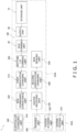
- FIG. 1 is a block diagram of the box forming and packing system 1.
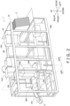
- FIG. 2 is a perspective view showing the configuration of the box forming and packing system 1.
- FIG. 3 is a perspective view showing a flow of cardboard sheets Z, cardboard boxes CB, and goods G in the box forming and packing system 1.
- the box forming and packing system 1 is a system that opens a collapsed cardboard sheet Z (i.e., a box preform in its flattened state) to form a square tubular cardboard box CB, forms a bottom lid B in the cardboard box CB, and packs goods G in the cardboard box CB in which the bottom lid B has been formed.
- a collapsed cardboard sheet Z i.e., a box preform in its flattened state
- the goods G are, for example, bags containing a snack food.
- the box forming and packing system 1 as shown in FIG. 1 and FIG. 2 , has a cardboard handling area DHA and a goods handling area GHA.
- the cardboard handling area DHA and the goods handling area GHA are interconnected in a state in which they are mutually independently separable.
- the goods handling area GHA alignment of the goods G, which are supplied from an apparatus (not shown in the drawings) for manufacturing the goods G, is performed.
- the aligned goods G are packed in the cardboard box CB in which the bottom lid B has been formed.
- a box forming apparatus 100 In the cardboard handling area DHA, a box forming apparatus 100, a bottom lid forming unit 200, a first orientation changing unit 510, a box downward conveyance unit 520, a goods receiving unit 530, a second orientation changing unit 540, and a box sealing unit 550 are mainly disposed (see FIG. 1 ).
- a goods feeding unit 310, a goods aligning unit 320, and a packing unit 300 are mainly disposed (see FIG. 1 ).
- the various devices in the cardboard handling area DHA and the various devices in the goods handling area GHA are electrically connected to a controller 400 that controls these devices (see FIG. 1 ).
- the box forming apparatus 100 mainly has a storage unit (storage) 10, a supply unit (supplier) 90, and a box forming unit 20 (see FIG. 1 ).
- the box forming apparatus 100 is an apparatus that opens the collapsed cardboard sheet Z to form the square tubular cardboard box CB.
- the storage unit 10 accommodates the cardboard box CB before it is opened, in other words, the cardboard sheet Z.
- the cardboard box CB has four side surfaces S (a first side surface S1, a second side surface S2, a third side surface S3, and a fourth side surface S4).
- the first side surface S1, the second side surface S2, the third side surface S3, and the fourth side surface S4 are consecutive in this order.
- the box forming apparatus 100 opens the cardboard sheet Z, the square tubular cardboard box CB in which the four side surfaces S are consecutive is formed (see FIG. 10 ).
- the cardboard box CB has flaps Fa that extend from each of the first side surface S1, the second side surface S2, the third side surface S3, and the fourth side surface S4 and are used to form the upper lid U of the cardboard box CB (see FIG. 3 ).
- the cardboard box CB also has flaps Fb that extend in the opposite direction of the flaps Fa from each of the first side surface S 1, the second side surface S2, the third side surface S3, and the fourth side surface S4 and are used to form the bottom lid B of the cardboard box CB (see FIG. 3 ).
- the first side surface S 1 and the second side surface S2 oppose the third side surface S3 and the fourth side surface S4 (see FIG. 7 ).
- the supply unit 90 supplies to a supply position the cardboard sheet Z placed in the storage unit 10.
- the supply position is a position at which the box forming unit 20 receives the cardboard sheet Z supplied by the supply unit 90.
- the box forming unit 20 opens the collapsed cardboard box CB, in other words, the collapsed cardboard sheet Z, to form the square tubular cardboard box CB.
- the bottom lid forming unit 200 is an example of a forming device.
- the bottom lid forming unit 200 has folding members 210 (see FIG. 3 ).
- the bottom lid forming unit 200 drives, with a drive unit such as an air cylinder or a motor (not shown in the drawings), the folding members 210 (see FIG. 3 ) to thereby bring the folding members 210 into contact with the flaps Fb of the cardboard box CB formed by the box forming apparatus 100 and fold the flaps Fb.
- a drive unit such as an air cylinder or a motor (not shown in the drawings)
- the folding members 210 see FIG. 3
- the bottom lid forming unit 200 folds the flaps Fb extending from the first side surface S 1 and the third side surface S3 and thereafter folds the flaps Fb extending from the second side surface S2 and the fourth side surface S4.
- the bottom lid forming unit 200 applies, with a tape application mechanism (not shown in the drawings), tape to the flaps Fb that have been folded by the folding members 210 to form the bottom lid B.
- the method by which the bottom lid forming unit 200 forms the bottom lid B is exemplary and is not limited to the above method.
- the bottom lid forming unit 200 may also form the bottom lid B without using tape by quarter-folding the flaps Fb.
- the first orientation changing unit 510 rotates the cardboard box CB, in which the bottom lid B has been formed and an opening not closed by the flaps Fa (hereinafter, simply called “the opening”) faces upward, 90° so that the opening faces forward. Specifically, the first orientation changing unit 510 rotates the cardboard box CB 90° about a horizontal axis extending in the left and right direction to change the orientation of the cardboard box CB so that the side surface S3 faces downward and the opening faces forward.
- the box downward conveyance unit 520 conveys downward the cardboard box B, which is in a first orientation in which the opening faces forward.
- the box downward conveyance unit 520 conveys downward the cardboard box CB in the first orientation by dropping it.
- the goods receiving unit 530 includes a holding member 532 that holds the third side surface S3 and the bottom lid B of the cardboard box CB.
- the goods receiving unit 530 receives the cardboard box CB in the first orientation conveyed thereto by the box downward conveyance unit 520 with the holding member 532, and holds them with the holding member 532.
- the holding member 532 holds the cardboard box CB in a state in which the opening of the cardboard box CB faces a push-in plate 302 (described later) of the packing unit 300 in the goods handling area GHA (see FIG. 2 ).
- the second orientation changing unit 540 changes the orientation of the cardboard box CB in which the goods G have been packed in the goods receiving unit 530 to an orientation in which the opening faces upward. Specifically, the second orientation changing unit 540 rotates the holding member 532 about a rotational axis extending in the left and right direction to thereby rotate the cardboard box CB, whose third side surface S3 is facing downward and whose opening is facing forward, so that the third side surface S3 faces forward and the opening faces upward.
- the holding member 532 is, for example, driven by an air cylinder (not shown in the drawings).
- the cardboard box CB whose orientation has been changed by the second orientation changing unit 540 is conveyed rearward by a conveyor 545.
- the box sealing unit 550 uses members (not shown in the drawings) to fold the flaps Fa of the cardboard box CB conveyed by the conveyor 545 and uses a tape applicator 552 to apply tape to the folded flaps Fa to form the upper lid U.
- a weighing apparatus, a bag making and packaging machine, and a goods inspection apparatus are disposed upstream of the box forming and packing system 1.
- the goods G that have been manufactured and passed inspections upstream of the box forming and packing system 1 are supplied to the box forming and packing system 1.
- the goods feeding unit 310 receives a supply of the goods G conveyed thereto by a conveyor (not shown in the drawings) from upstream of the box forming and packing system 1 and conveys the received goods G to the goods aligning unit 320.
- the goods aligning unit 320 includes plural conveyors 322, 324, 326.
- the goods aligning unit 320 uses the plural conveyors 322, 324, 326 to convey, while collecting, the goods G to a predetermined position (in back of the push-in plate 302 of the packing unit 300).
- the packing unit 300 is an example of a packing apparatus.
- the packing unit 300 mainly has the push-in plate 302.
- the packing unit 300 packs, in the cardboard box CB in which the bottom lid B has been formed and which is being held by the goods receiving unit 530, the goods G conveyed thereto by the goods aligning unit 320.
- the packing unit 300 uses a drive unit (e.g., an air cylinder or a motor not shown in the drawings) to move the push-in plate 302 rearward to thereby push the goods G that have been conveyed to the back of the push-in plate 302 into the cardboard box CB being held by the goods receiving unit 530 through the opening of the cardboard box CB.
- a drive unit e.g., an air cylinder or a motor not shown in the drawings
- the controller 400 is a control device that mainly includes a CPU, a storage device including a ROM, a RAM, and an auxiliary storage device (e.g., flash memory), and an input/output interface.
- the controller 400 controls the operations of the various devices of the box forming and packing system 1 as a result of the CPU executing programs stored in the storage device. It will be noted that the controller 400 need not have all its functions realized by software and may have some of its functions realized by hardware such as a logic circuit. Furthermore, the controller 400 may be realized by one device or may be realized by plural devices.
- the controller 400 is electrically connected to the various devices in the cardboard handling area DHA and the various devices in the goods handling area GHA. By executing the programs stored in the storage device, the controller 400 controls the operations of the various devices so that these devices execute predetermined operations at predetermined timings.
- the box forming apparatus 100 will now be described in greater detail with reference to FIG. 4 to FIG. 10 in addition to FIG. 1 to FIG. 3 .
- FIG. 4A and FIG. 4B are schematic plan views of the storage unit 10. It will be noted that the sizes of the cardboard sheets Z accommodated in the storage unit 10 differ between FIG. 4A and FIG. 4B .
- FIG. 5 is a schematic plan view of main portions of the box forming unit 20.
- FIG. 6 is a block diagram of the box forming apparatus 100. It will be noted that the controller 400 shown in FIG. 6 controls the operations of the various devices in the cardboard handling area DHA and the various devices in the goods handling area GHA as mentioned above. However, below, description about the control of the controller 400 to other than the box forming apparatus 100 will be omitted.
- FIG. 6 is a block diagram of the box forming apparatus 100. It will be noted that the controller 400 shown in FIG. 6 controls the operations of the various devices in the cardboard handling area DHA and the various devices in the goods handling area GHA as mentioned above. However, below, description about the control of the controller 400 to other than the box forming apparatus 100 will be omitted.
- FIG. 6 controls the operations
- FIG. 7 is a schematic plan view of main portions of the box forming apparatus 100 for describing the operation of opening the cardboard sheet Z performed by the box forming apparatus 100, and shows a state before the opening of the cardboard sheet Z is started.
- FIG. 8 is a schematic plan view of main portions of the box forming apparatus 100 for describing the operation of opening the cardboard sheet Z performed by the box forming apparatus 100, and shows a state in the middle of the operation of opening the cardboard sheet Z.
- FIG. 9 is a schematic plan view showing the state of main portions of the box forming apparatus 100 when the opening of the cardboard sheet Z is completed, in a case where it is assumed that a second moving unit 70 is not provided to the box forming apparatus 100.
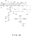
- FIG. 10 is a schematic plan view of main portions of the box forming apparatus 100 for describing the operation of opening the cardboard sheet Z performed by the box forming apparatus 100, and shows a state in which the opening of the cardboard sheet Z is completed. It will be noted that, in FIG. 7 to FIG. 10 , illustration of a linkage 64 of a first moving unit 60 described later is omitted.
- the storage unit 10 accommodates the cardboard sheet Z.
- the storage unit 10 accommodates a plurality of the cardboard sheets Z arranged side by side (i.e., stacked) along the front and rear direction. Specifically, in the storage unit 10, as shown in FIG. 3 , the plural cardboard sheets Z are stored leaning against one another so that the side surfaces S and the flaps Fa, Fb of the cardboard sheets Z contact the side surfaces S and the flaps Fa, Fb of adjacent cardboard sheets Z in front and in back. Furthermore, in the storage unit 10, as shown in FIG. 3 , the cardboard sheets Z are stored so that the flaps Fa are disposed on top and the flaps Fb are disposed on bottom.
- the cardboard sheets Z are stored so that the first side surfaces S 1 and the second side surfaces S2 are disposed in front and the third side surfaces S4 and the fourth side surfaces S4 are disposed in back. Furthermore, in the storage unit 10, the cardboard sheets Z are stored so that the first side surfaces S1 are disposed on the left side of the second side surfaces S2 and the third side surfaces S3 are disposed on the right side of the fourth side surfaces S4.
- the cardboard sheets Z placed in the storage unit 10 are sequentially fed upward by the supply unit 90 one sheet at a time beginning with the foremost cardboard sheet Z, and are supplied to the box forming unit 20.
- a push member 14 contacts the rearmost cardboard sheet Z among the cardboard sheets Z placed in the storage unit 10.
- the push member 14 is energized by an elastic member such as a spring to cause a forward force to act on the rearmost cardboard sheet Z.
- the cardboard sheets Z in the storage unit 10 are placed on a conveyor (not shown in the drawings) that conveys the cardboard sheets Z forward. Due to the movement of the conveyor and the push member 14, when the supply unit 90 feeds the foremost cardboard sheet Z upward, the cardboard sheet Z that had been adjacent to it (that had been disposed second from the front) moves to a position at which the supply unit 90 can feed it.
- the storage unit 10 have a positioning mechanism (positioner) 12 that adjusts a storage position of the cardboard sheets Z.
- the positioning mechanism 12 has, for example, a pair of tabular members 12a arranged side by side an interval apart from each other to the left and right.
- the cardboard sheets Z accommodated in the storage unit 10 are disposed between the pair of tabular members 12a.
- Each of the pair of tabular members 12a is a member that can move in the left and right direction independently of the other tabular member 12a.
- the tabular member 12a on the right side among the pair of tabular members 12a regulates the right-side position of the cardboard sheets Z
- the tabular member 12a on the left side among the pair of tabular members 12a regulates the left-side position of the cardboard sheets Z.
- the cardboard sheets Z placed in the storage unit 10 are moved upward by the supply unit 90 and supplied to the box forming unit 20.
- the supply unit 90 may move the cardboard sheets Z in the front and rear direction but does not move them in the right and left direction. For that reason, the cardboard sheets Z accommodated in the storage unit 10 are supplied to the box forming unit 20 without their position in the left and right direction being changed.
- the box forming unit 20 opens the cardboard sheet Z by holding the first side surface S 1 and the second side surface S2 of the cardboard sheet Z and bending the cardboard box Z at the boundary (called a boundary X) between the first side surface S1 and the second side surface S2.
- a boundary X between the first side surface S1 and the second side surface S2.
- the box forming unit 20 may not be able to hold with the holding units 42, 44 the first side surface S1 and the second side surface S2 at appropriate positions and may not be able to properly bend the cardboard sheet Z at the boundary X, thus running the risk that problems such as the cardboard sheet Z being damaged or deformed will occur.
- the boundary X can be positioned in the same position by adjusting the positions of the tabular members 12a in the left and right direction no matter the size of the cardboard sheets Z (see FIG. 4A and FIG. 4B ). As a result, the occurrence of damage and deformation in the cardboard sheet Z can be inhibited.
- the tabular members 12a may be members that are manually moved or members that are moved by a machine such as a motor. Furthermore, in a case where the tabular members 12a are moved by a motor or the like, when information relating to the size of the cardboard sheets Z is input to the controller 400 via an input unit (not shown in the drawings), the controller 40 may automatically adjust the positions of the tabular members 12a in conformity with the size of the cardboard sheets Z.
- the information relating to the size of the cardboard sheets Z is, for example, information about the size itself of the cardboard sheets Z.
- the information relating to the size of the cardboard sheets Z may be information relating to the type of the cardboard sheets Z.
- the supply unit (supplier) 90 supplies to the supply position the cardboard sheet Z accommodated in the storage unit 10.
- the supply position is a position at which the box forming unit 20 receives the cardboard sheet Z supplied by the supply unit 90.
- the supply unit 90 mainly has a lift mechanism 92, holding suckers 94, and a suction mechanism 98 (see FIG. 3 , FIG. 6 , and FIG. 7 ).
- the lift mechanism 92 holds with suckers 92a a side surface (at least one of the first side surface S 1 and the second side surface S2) on the front side of the foremost cardboard sheet Z in the storage unit 10 (see FIG. 3 ).
- the lift mechanism 92 feeds upward the foremost cardboard sheet Z in the storage unit 10 by moving a support unit 92b of the suckers 92a upward (see FIG. 3 ).
- the movement of the support unit 92b in the up and down direction is realized by, for example, an air cylinder or a motor (not shown in the drawings).
- the holding suckers 94 are supported by a support member 96 (see FIG. 7 ).
- the holding suckers 94 suck hold of a side surface (at least one of the third side surface S3 and the fourth side surface S4) on the rear side of the cardboard sheet Z that the lift mechanism 92 is conveying to the supply position and hold the cardboard sheet Z in the supply position until the box forming unit 20 receives the cardboard sheet Z.
- the suction mechanism 98 is a mechanism that applies a suction force to the suckers 92a and the holding suckers 94.
- the suction mechanism 98 is, for example, a vacuum pump.
- the box forming unit 20 opens the cardboard sheet Z that has been handed over from the supply unit 90 to form the square tubular cardboard box CB.
- the box forming unit 20 mainly includes first holding units (first holders) 42, second holding units (second holders) 44, a suction mechanism 46, an arm 50, a first moving unit (first mover) 60, and a second moving unit (second mover) 70.
- the box forming unit 20 has two first holding units (first holders) 42 that hold the first side surface S1 of the cardboard sheet Z supplied by the supply unit 90.
- the first holding units 42 are suckers.
- the first holding units 42 are supported by a first support unit (support) 52a of the arm 50.
- the number of the first holding units 42 that the box forming unit 20 has is not limited to two and may be one or three or more. It suffices for the number of the first holding units 42 to just be a number appropriate for holding the first side surface S1.
- the two first holding units 42 are disposed at the same height in the vertical direction and apart from each other in the horizontal direction.
- the first support unit 52a of the arm 50 supports the two first holding units 42 in a state in which they are at the same height in the vertical direction and apart from each other in the horizontal direction.
- the arrangement of the first holding units 42 is not limited to this arrangement.
- the two first holding units 42 may also be disposed at mutually different heights in the vertical direction and in the same positions in the horizontal direction.
- the box forming unit 20 has two second holding units (second holder) 44 that hold the second side surface S2 of the cardboard sheet Z supplied by the supply unit 90.
- the second holding units 44 are suckers.
- the second holding units 44 are supported by a second support unit 52b of the arm 50.
- the number of the second holding units 44 that the box forming unit 20 has is not limited to two and may be one or three or more. It suffices for the number of the second holding units 44 to just be a number appropriate for holding the second side surface S2.
- the two second holding units 44 are disposed at the same height in the vertical direction and apart from each other in the horizontal direction.
- the second support unit 52b of the arm 50 supports the two second holding units 44 in a state in which they are at the same height in the vertical direction and apart from each other in the horizontal direction.
- the arrangement of the second holding units 44 is not limited to this arrangement.
- the two second holding units 44 may also be disposed at mutually different heights in the vertical direction and in the same positions in the horizontal direction.
- the number of the second holding units 44 and the number of the first holding units 42 are the same, the number of the second holding units 44 and the number of the first holding units 42 are not limited to this and may also be mutually different.
- the suction mechanism 46 is a mechanism that applies suction force to the first holding units 42 and the second holding units 44.
- the suction mechanism 46 is, for example, a vacuum pump.
- the arm 50 is used when opening the cardboard sheet Z.
- the arm 50 may be a single member or a member formed by combining plural members.
- the arm 50 is rotatably supported by a rotating shaft 50a.
- the rotating shaft 50a extends in the vertical direction.
- the arm 50 rotates about a rotational center O.
- the arm 50 is a bar-shaped member that extends from an end portion 53 near the rotating shaft 50a to a distal end 51 disposed in a position away from the rotating shaft 50a. Below, the direction extending from the end portion 53 to the distal end 51 will sometimes be called the lengthwise direction of the arm 50.
- the arm 50 has a support unit (support) 52 that supports the first holding units 42 and the second holding units 44 (see FIG. 3 ).
- the support unit 52 includes the first support unit 52a that supports the first holding units 42 and the second support unit 52b that supports the second holding units 44.
- the first holding units 42 are attached to a linkage 64 that is attached to the arm 50.
- the first support unit 52a supports the first holding units 42 via the linkage 64 that is attached to the arm 50.
- the second support unit 52b supports the second holding units 44 directly (i.e., without the intervention of a link mechanism).
- the arm 50 extends such that its lengthwise direction coincides with the left and right direction. Furthermore, the first holding units 42 and the second holding units 44 supported by the arm 50 are disposed side by side in a straight line in the left and right direction (see the first holding units 42 and the second holding units 44 shown by the solid lines in FIG. 5 ). Furthermore, when the first holding units 42 and the second holding units 44 receive from the supply unit 90 the cardboard sheet Z supplied to the supply position, the first holding units 42 are disposed on the left side of the second holding units 44 in conformity with the arrangement of the first side surface S 1 and the second side surface S2 of the cardboard sheet Z in the supply position.
- the position of the first holding units 42 relative to the second holding units 44 changes, so that the direction in which the two first holding units 42 form a line and the direction in which the two second holding units 44 form a line come to intersect each other (see FIG. 8 ).
- the arm 50 rotates counterclockwise in plan view.
- the direction in which the two first holding units 42 form a line and the direction in which the two second holding units 44 form a line become orthogonal to each other (see the first holding units 42 and the second holding units 44 shown by the dashed lines in FIG. 5 ).
- the first moving unit (first mover) 60 changes the position of the first holding units 42 relative to the second holding units 44 while rotating the arm 50 to open the cardboard sheet Z.
- the first moving unit 60 mainly has a first drive mechanism (actuator) 62 and the linkage (link mechanism) 64.
- the first drive mechanism 62 rotates the arm 50.
- the first drive mechanism 62 is, for example, an air cylinder or a motor.
- the linkage 64 changes the position of the first holding units 42 relative to the second holding units 44 in accompaniment with the rotation of the arm 50.
- the linkage 64 is simultaneously driven by the first drive mechanism 62 that rotates the arm 50 to change the position of the first holding units 42 relative to the second holding units 44.
- the linkage 64 includes plural links 64a, a fixed end 64b that connects some of the links 64a to the arm 50, and joints 64c that interconnect the links 64a (see FIG. 5 ).
- the first holding units 42 are attached to a first link 64a1 that is one of the links 64a.
- the links 64a connected to the arm 50 by the fixed end 64b are rotatable about the fixed end 64b but do not move away from the arm 50.
- the linkage 64 changes the position of the first holding units 42, which are attached to the first link 64a1, relative to the second holding units 44 so that the first side surface S1 held by the first holding units 42 rotates about the boundary X between the first side surface S1 and the second side surface S2 with respect to the second side surface S2 held by the second holding units 44 in accompaniment with the rotation of the arm 50 (see FIG. 7 , FIG. 8 , and FIG. 10 ).
- the arm 50 rotates 90° about the rotational center O from the state in which the lengthwise direction of the arm 50 coincides with the left and right direction (the state in which the arm 50 is disposed when the first holding units 42 and the second holding units 44 receive from the supply unit 90 the cardboard sheet Z supplied to the supply position; hereinafter, sometimes called “the initial state") to the state in which the lengthwise direction of the arm 50 coincides with the front and rear direction, the first side surface S1 held by the first holding units 42 and the second side surface S2 held by the second holding units 44 become orthogonal to each other, and the opening of the cardboard sheet Z by the first moving unit 60 is completed (see FIG. 10 ).
- the second moving unit (second mover) 70 moves the arm 50 in a case where the cardboard sheet Z is opened. More specifically, the second moving unit 70 moves the entire arm 50 with respect to a frame 80 of the box forming and packing system 1 in a case where the cardboard sheet Z is opened.
- the second moving unit 70 moves the arm 50 so that, at the point in time when the opening of the cardboard sheet Z is completed, the second moving unit 70 has moved the support unit 52 a predetermined distance L in a second direction D2 opposite a first direction D1 compared with the case where the second moving unit 70 does not move the arm 50.
- the first direction D1 is a direction heading from the rotational center O of the arm 50 to the distal end 51 of the arm 50 at the point in time when the opening of the cardboard sheet Z is completed.
- the first direction D1 is the lengthwise direction of the arm 50 at the point in time when the opening of the cardboard sheet Z is completed.
- the second moving unit 70 has moved the support unit 52 the predetermined distance L in the second direction D2 (rearward) opposite the first direction D1 (forward) which is a direction heading from the rotational center O of the arm 50 to the distal end 51 of the arm 50.
- the second moving unit 70 specifically moves the rotational center O of the arm 50 (the rotating shaft 50a that rotatably supports the arm 50) in the second direction D2.
- the second moving unit 70 mainly has a support member 74, which supports the rotating shaft 50a of the arm 50, and a second drive mechanism 72.
- the second drive mechanism 72 is, for example, an air cylinder or a motor.
- the support member 74 is a member supported by the frame 80, which extends in the front and rear direction of the box forming and packing system 1, in a state in which the support member 74 is movable in the front and rear direction with respect to the frame 80.
- the support member 74 is driven by the second drive mechanism 72 to move in the front and rear direction along the frame 80.
- the support member 74 is movable between a first position P1 (see the position of the support member 74 shown by the dashed line in FIG. 10 ) and a second position P2 (see the position of the support member 74 shown by the solid line in FIG. 10 ).
- the support member 74 When the arm 50 extends in the left and right direction (when the arm 50 is in the initial state) and the first holding units 42 and the second holding units 44 receive the cardboard sheet Z supplied to the supply position, the support member 74 is disposed in the first position P1. By contrast, at the point in time when the arm 50 has rotated 90° about the rotational center O and the opening of the cardboard sheet Z is completed, the support member 74 is disposed in the second position P2.
- the support unit 52 of the arm 50 has moved the predetermined distance L in the second direction D2 compared with a case where the support member 74 does not move in the second direction D2 (a case where the support member 74 is immovable in the first position P1). In other words, as shown in FIG.
- the first holding units 42 and the second holding units 44 have moved the predetermined distance L in the second direction D2 compared with a case where the support member 74 does not move in the second direction D2 (see and compare 1) the positions of the first holding units 42 and the second holding units 44 shown by the dashed lines in FIG. 10 for a (comparative) case in which the support member 74 does not move in the second direction D2 and 2) the positions of the first holding units 42 and the second holding units 44 shown by the solid lines in FIG. 10 for a case in which the support member 74 has moved to the second position P2).
- the cardboard sheet Z (i.e., the now-opened cardboard box DB) has moved the predetermined distance L in the second direction D2 compared with a case where the support member 74 does not move in the second direction D2.
- the rear end of the cardboard sheet Z (i.e., the now-opened cardboard box CB) is positioned forward of the supply position to which the supply unit 90 supplies the cardboard sheet Z.
- the position of the rear end of the cardboard sheet Z is not limited to this, and at the point in time when the opening of the cardboard sheet Z is completed the rear end of the cardboard sheet Z (the opened cardboard box CB) may also be positioned rearward of the supply position to which the supply unit 90 supplies the cardboard sheet Z.
- the arm 50 Before the arm 50 starts opening the cardboard sheet Z (when the arm 50 is in the initial state), the arm 50 extends in the left and right direction as in FIG. 7 . By contrast, when the arm 50 rotates about the rotational center O extending in the vertical direction, the distal end 51 of the arm 50 gradually moves forward. Furthermore, the cardboard sheet Z that is opened by the arm 50 also gradually moves forward (see FIG. 8 ). Then, at the point in time when the arm 50 has rotated 90° about the rotational center O extending in the vertical direction and the opening of the cardboard sheet Z is completed, the arm 50 extends forward from the rotational center O (see FIG. 9 ). Furthermore, the opened cardboard box CB has moved forward from the view of the supply position of the cardboard sheet Z.
- the cardboard box CB would have moved a large amount forward from the view of the supply position of the cardboard sheet Z.
- Members configuring the box forming apparatus 100 and members configuring the box forming and packing system 1 (members other than the members configuring the box forming apparatus 100) cannot be disposed in the space in which the arm 50 and the cardboard sheet Z (the cardboard box CB) move. Consequently, in a case where the box forming apparatus 100 does not have the second moving unit 70, the sizes of the box forming apparatus 100 and the box forming and packing system 1 in the front and rear direction tend to increase.
- the second moving unit 70 moves the arm 50 by moving the support member 74, and at the point in time when the opening of the cardboard box Z is completed, the second moving unit 70 has moved the support unit 52 of the arm 50 the predetermined distance L in the second direction D2 compared to a case where the second moving unit 70 has not moved the arm 50, so the space in which the arm 50 and the cardboard sheet Z (the now-opened cardboard box CB) move can be reduced (see FIG. 10 ). As a result, an increase in the sizes of the box forming apparatus 100 and the box forming and packing system 1 in the front and rear direction can be inhibited.
- FIG. 8 shows a state in which the support member 74 is in the first position P1
- the controller 400 controls the operation of the second moving unit 70 so that the second moving unit 70 starts moving the support member 74 while the arm 50 is rotating.
- the controller 400 may control the operation of the second drive mechanism 72 to move the support member 74 rearward from the first position P1 at the stage when the arm 50 is in a rotational state such as shown in FIG. 8 .
- the controller 400 controls the second drive mechanism 72 to move the support member 74 at a predetermined timing so that, while the support member 74 is moving from the first position P1 to the second position P2, the arm 50 and the cardboard sheet Z do not come into contact with members disposed rearward of them.
- the second drive mechanism 72 may move the support member 74 at a generally constant moving speed from the first position P1 to the second position P2 or may change the moving speed midway.
- the second drive mechanism 72 may move the support member 74 continuously from the first position P1 to the second position P2 or may move the support member 74 discontinuously so as to temporarily stop midway.
- the box forming apparatus 100 does not always handle cardboard sheets Z (cardboard boxes CB) of the same size, and sometimes the size of the cardboard sheets Z that the box forming apparatus 100 handles changes.
- the position that the opened cardboard sheet Z (the cardboard box CB) reaches in the forward direction with respect to the supply position to which the supply unit 90 supplies the cardboard sheet Z differs depending on the size of the cardboard sheet Z (the cardboard box CB).
- the opened cardboard sheet Z might not come into contact with members configuring the box forming apparatus 100 or members configuring the box packing and forming system 1 (members other than the members configuring the box forming apparatus 100) even if the support member 74 is not moved rearward or even if the moving amount of the support member 74 in the rearward direction is relatively small.
- the box forming apparatus 100 have a changing unit (Changer) that can change the predetermined distance L the second moving unit 70 moves the support unit 52 of the arm 50.
- the box forming apparatus 100 have a changing unit that can change the second position P2.
- the expression "can change the predetermined distance L" may also include an aspect that makes the predetermined distance L zero.
- the changing unit may, as indicated by reference sign "410" in FIG. 6 , be a unit that the controller 400 has.
- the changing unit 410 of the controller 400 changes the moving distance of the support unit 52 (in other words, the moving distance of the support member 74) by, for example, changing the control content of a motor serving as the second drive mechanism 72.
- the changing unit may, instead of being a unit that the controller 400 has, be a mechanism that physically changes (limits) the moving range of the support member 74.
- the second drive mechanism 72 may have the changing unit.
- the changing unit 72a here is, for example, a stroke adjusting mechanism that changes the stroke of an air cylinder serving as the second drive mechanism 72.
- the box forming apparatus 100 opens the collapsed cardboard sheet Z in which the first side surface S1 and the second side surface S2 oppose the third side surface S3 and the fourth side surface S4 to form the square tubular cardboard box CB in which the first side surface S1, the second side surface S2, the third side surface S3, and the fourth side surface S4 are consecutive in this order.
- the box forming apparatus 100 includes the first holding units (first holder) 42, the second holding units (second holder) 44, the arm 50, the first moving unit (first mover) 60, and the second moving unit (second mover) 70.
- the first holding units 42 hold the first side surface S1 of the cardboard sheet Z.
- the second holding units 44 hold the second side surface S2 of the cardboard sheet Z.
- the arm 50 has the support unit (support) 52 that supports the first holding units 42 and the second holding units 44.
- the arm 50 rotates about the rotational center O.
- the first moving unit 60 changes a position of the first holding units 42 relative to the second holding units 44 while rotating the arm 50 to open the cardboard sheet Z.
- the second moving unit 70 moves the support unit 52 or the arm 50 in association with the opening of the cardboard sheet Z.
- the second moving unit 70 moves the support unit 52 or the arm 50 so that, at the point in time when the opening of the cardboard sheet Z is completed, the second moving unit 70 has moved the support unit 52 the predetermined distance L in the second direction D2 opposite the first direction D1 compared with a case where the second moving unit 70 does not move the support unit 52 or the arm 50,.
- the first direction D1 is a direction heading from the rotational center O of the arm 50 to the distal end 51 of the arm 50 at the point in time when the opening of the cardboard sheet Z is completed.
- the first direction D1 is forward and the second direction D2 is rearward.
- the second moving unit 70 moves the rotational center O of the arm 50 in the second direction D2.
- the second moving unit 70 moves the support unit 52 or the arm 50 so that, at the point in time when the opening of the cardboard sheet Z is completed, the support unit 52 has been moved in the second direction D2 compared with a case where the second moving unit 70 does not move the support unit 52 or the arm 50.
- moving space for the arm 50 and the cardboard sheet Z held by the holding units 42, 44 can be ensured while reducing the length of the box forming apparatus in the first direction D1.
- the rotational center O of the arm 50 is moved in the second direction D2 in in association with rotating the arm 50 to open the cardboard sheet Z. Because the box forming apparatus 100 is configured in this way, with relatively simple structure, moving space for the arm 50 and the cardboard sheet held by the holding units 42, 44 can be ensured while reducing the length of the box forming apparatus 100 in the first direction D1.
- the first moving unit 60 has the first drive mechanism 62 that rotates the arm 50 and the linkage 64 that changes the position of the first holding units 42 relative to the second holding units 44 in accompaniment with the rotation of the arm 50.
- the first drive mechanism 62 is an example of an actuator.
- the position of the first holding units 42 relative to the second holding units 44 is changed by the linkage 64 in conjunction with the rotation of the arm 50. For that reason, the rotation of the arm 50 and the changing of the position of the first holding units 42 relative to the second holding units 44 can be realized with a single drive mechanism.
- the timing of the rotation of the arm 50 and the timing of the changing of the position of the first holding units 42 relative to the second holding units 44 can be synchronized. Therefore, the occurrence of deformation and damage in the cardboard box CB that the box forming apparatus 100 opens can be inhibited.
- the box forming apparatus 100 includes the storage unit (storage) 10 and the supply unit (supplier) 90.
- the storage unit 10 stores the cardboard sheet Z.
- the supply unit 90 supplies to the supply position the cardboard sheet Z placed in the storage unit 10.
- the storage unit 10 has the positioning mechanism (positioner) 12 that adjusts the storage position of the cardboard sheet Z.
- the cardboard sheet Z can be supplied to the supply position so that the position of the boundary X between the first side surface S1 and the second side surface S2 (in other words, the position at which the cardboard sheet Z is bent) is always in the same position even when the size of the cardboard sheet Z changes. For that reason, in this box forming apparatus 100, even when the size of the cardboard sheet Z changes, it is not necessary to adjust the positions of various constituent parts in the mechanisms for box forming, and operability is therefore good. Furthermore, a configuration or structure for adjusting the positions of various constituent parts in the mechanisms for box forming, which are constituently complex, is not required, so an increase in the cost of the box forming apparatus 100 can also be inhibited.
- the box forming apparatus 100 further includes a changing unit (Changer) that changes the predetermined distance L (the moving amount in which the second moving unit 70 moves the support unit 52).
- a changing unit that changes the predetermined distance L (the moving amount in which the second moving unit 70 moves the support unit 52).
- the changing unit may, as indicated by reference sign "410" in FIG. 6 , be a unit that the controller 400 has, and the changing unit 410 may change the control content of a motor serving as the second drive mechanism 72. Furthermore, the changing unit may, as indicated by reference sign "72a” in FIG. 6 , be a unit that the second drive mechanism 72 has.
- the changing unit 72a in this box is, for example, a stroke adjusting mechanism that changes the stroke of an air cylinder serving as the second drive mechanism 72.
- the occurrence of a situation where the second moving unit 70 moves the support unit 52 of the arm 50 an unnecessarily large amount in the second direction D2 can be inhibited. Furthermore, in the box forming apparatus 100, the occurrence of a converse situation where the moving amount of the support unit 52 of the arm 50 in the second direction D2 is not enough can also be inhibited.
- the box forming and packing system 1 includes the box forming apparatus 100, the bottom lid forming unit 200 serving as an example of a forming device, and the packing unit 300 serving as an example of a packing apparatus.
- the bottom lid forming unit 200 forms the bottom lid B in the cardboard box CB that has been opened by the box forming apparatus 100.
- the packing unit 300 packs the goods G in the cardboard box CB in which the bottom lid B has been formed.
- an increase in the size of the box forming apparatus 100 can be inhibited, so an increase in the size of the box forming and packing system 1 overall can be inhibited.
- the box forming apparatus 100 includes in its configuration the storage unit 10, the supply unit 90, and the box forming unit 20, but the box forming apparatus 100 is not limited to this.
- the box forming apparatus 100 may also include in its configuration the bottom lid forming unit 200 in addition to the storage unit 10, the supply unit 90, and the box forming unit 20.
- the box forming apparatus 100 may be an apparatus that is independent of the packing apparatus and forms from the cardboard sheet Z the cardboard box CB in which the bottom lid B is formed.
- the cardboard box CB formed by the box forming apparatus 100 may be supplied by a conveyor or a robot (not shown in the drawings), for example, to a location that requires the cardboard box CB.
- the box forming and packing system 1 of the above embodiment is merely an embodiment, and various changes may be made thereto.
- the packing apparatus of the box forming and packing system 1 may be an apparatus that puts the goods G from above into the cardboard box CB in which the opening not closed by the flaps Fa faces upward.
- the first orientation changing unit 510 and the second orientation changing unit 540 that change the orientation of the cardboard box CB are unnecessary.
- the second moving unit 70 of the box forming apparatus 100 of the above embodiment moves the rotational center O of the arm 50 by moving the support member 74 rearward.
- the second moving unit 70 is not limited to this and need not move the rotational center O of the arm 50.
- the rotating shaft 50a of the arm 50 may be directly attached to the frame 80 without the box forming apparatus 100 being provided with the support member 74.
- the rotating shaft 50a of the arm 50 does not move forward and rearward.
- the arm 50 is provided with a telescoping unit 74a that extends and retracts along the lengthwise direction of the arm 50, and the telescoping unit 74a functions as part of the second moving unit 70.
- the second moving unit 70 in the box forming apparatus 100 of example modification C includes the telescoping unit 74a provided in the arm 50 and the second drive mechanism 72.
- the second drive mechanism 72 is, for example, an air cylinder or a motor as in the above embodiment.
- the second drive mechanism 72 is used to drive the telescoping unit 74a instead of driving the support member 74.
- the telescoping unit 74a is, for example, a rod having a telescope structure provided nearer the rotating shaft 50a than the support unit 52 of the arm 50.
- the telescoping unit 74a has a rod that is driven in the lengthwise direction of the arm 50 by the second drive mechanism 72 and a hollow rod that can accommodate this rod inside.
- the support unit 52 of the arm 50 moves toward or away from the rotating shaft 50a of the arm along the lengthwise direction of the arm 50.
- the second moving unit 70 may move the support unit 52 without changing the position of the rotational center O of the arm 50 in a case where the opening of the cardboard sheet Z.
- the second moving unit 70 moves the support unit 52 so that, at the point in time when the opening of the cardboard sheet Z is completed, the second moving unit 70 has moved the support unit 52 the predetermined distance L in the second direction D2 opposite the first direction D1 compared with a case where the second moving unit 70 has not moved the support unit 52.
- the second moving unit 70 moves the support unit 52 so that, the second moving unit 70 moves the first holding units 42 and the second holding units 44 the predetermined distance L compared with a case where the second moving unit 70 has not moved the support unit 52 (see and compare 1) the first holding units 42 and the second holding units 44 shown by the dashed lines (a comparative case where the second moving unit 70 has not moved the support unit 52) and 2) the first holding units 42 and the second holding units 44 shown by the solid lines (a case where the second moving unit 70 has moved the support unit 52)).
- the length of the box forming apparatus 100 in the first direction D1 can be reduced, and moving space for the cardboard sheet Z held by the first holding units 42 and the second holding units 44 can be ensured.
- the box forming apparatus 100 of the above embodiment rotates the arm 50 about the rotational center O extending in the vertical direction to open the cardboard sheet Z that the supply unit 90 supplies to the supply position in a state in which the first side surface S1 is disposed on the left side and the second side surface S2 is disposed on the right side.
- the box forming apparatus 100 is not limited to this.
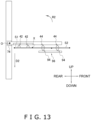
- the box forming apparatus 100 may also rotate the arm 50 about the rotational center O extending in the left and right direction (see arrow R1 in the drawing) to open the cardboard sheet Z that the supply unit 90 supplies to the supply position in a state in which the first side surface S 1 is disposed on bottom and the second side surface S2 is disposed on top.
- the second moving unit 70 moves the support unit 52 or the arm 50 so that, at the point in time when the opening of the cardboard sheet Z is completed, the second moving unit 70 has moved the support unit 52 a predetermined distance rearward (the second direction D2) compared with a case where the second moving unit 70 has not moved the support unit 52 or the arm 50.
- the box forming apparatus 100 may also rotate the arm 50 about the rotational center O extending in the left and right direction (see arrow R2 in the drawing) to open the cardboard sheet Z in a horizontal state supplied to the supply position in a state in which the first side surface S1 is disposed in back and the second side surface S2 is disposed in front.
- the second moving unit 70 moves the support unit 52 or the arm 50 so that, at the point in time when the opening of the cardboard sheet Z is completed, the second moving unit 70 has moved the support unit 52 a predetermined distance downward and rearward (the second direction D2) compared with a case where the second moving unit 70 has not moved the support unit 52 or the arm 50.
- the box forming apparatus 100 is configured in this way, the height of the box forming apparatus 100 can be reduced.
- the linkage 64 that changes the position of the first holding units 42 relative to the second holding units 44 is also driven by the first drive mechanism 62 that rotates the arm.
- the first moving unit 60 is not limited to this and may also have a drive mechanism separate from the first drive mechanism 62 and a mechanism that is driven by this drive mechanism to change the position of the first holding units 42 relative to the second holding units 44.
- the present invention is widely applicable to box forming apparatus and box forming and packing systems having a box forming apparatus, and is thus useful.
- Patent Document 1 JP-A No. 2019-147582
Landscapes
- Engineering & Computer Science (AREA)
- Mechanical Engineering (AREA)
- Supplying Of Containers To The Packaging Station (AREA)
Abstract
A box forming apparatus includes first holders configured to hold a first side surface of a cardboard sheet, second holders configured to hold a second side surface of the cardboard sheet, an arm, a first mover, and a second mover. The arm has a support that supports the first and the second holders. The first mover changes a position of the first holders relative to the second holders while the arm is being rotated to open the cardboard sheet. The second mover moves the arm in association with opening of the cardboard sheet so that, when the cardboard sheet has been opened, the second mover will have moved the support a predetermined distance in a second direction opposite a first direction, which is a direction heading from a rotational center of the arm to a distal end of the arm.
Description
- The present invention relates to a box forming apparatus and a box forming and packing system that includes the box forming apparatus.
- Conventionally, a box forming apparatus is known which, as in patent document 1 (
JP-ANo. 2019-147582 - The box forming apparatus disclosed in patent document 1 (
JP-A No. 2019-147582 - It is an object of the present invention to provide a box forming apparatus that can inhibit an increase in apparatus size.
- A box forming apparatus in accordance with a first aspect of the invention opens a collapsed cardboard sheet (i.e., a box preform in its flattened state) in which a first side surface and a second side surface oppose a third side surface and a fourth side surface to form a square tubular cardboard box in which the first side surface, the second side surface, the third side surface, and the fourth side surface are consecutive in this order. The box forming apparatus includes a first holder, a second holder, an arm, a first mover, and a second mover. The first holder is configured to hold the first side surface of the cardboard sheet. The second holder is configured to hold the second side surface of the cardboard sheet. The arm has a support configured to support the first holder and the second holder. The arm is configured to rotate about a rotational center. The first mover is configured to change a position of the first holder relative to the second holder while the arm is being rotated to open the cardboard sheet. The second mover is configured to move the support or the arm, in association with rotation of the arm to open the cardboard sheet, the support or the arm in a second direction opposite to a first direction. The second mover is configured to move the support or the arm, such that the support is moved in the second direction, when opening of the cardboard sheet is completed, by a predetermined distance relative to a position where the support would be disposed if the support or the arm were not moved by the second mover. The first direction is a direction heading from the rotational center of the arm to a distal end of the arm when the opening of the cardboard sheet is completed.
- In the box forming apparatus of the first aspect, the second mover moves the support or the arm so that, at the point in time when the opening of the cardboard sheet is completed, the support has been moved in the second direction compared with a case where the second mover does not move the support or the arm. As a result, moving space for the arm and the cardboard sheet held by the holders can be ensured while reducing the length of the box forming apparatus in the first direction.
- A box forming apparatus in accordance with a second aspect of the invention is the box forming apparatus of the first aspect, wherein the second mover is configured to move the rotational center of the arm in the second direction.
- In the box forming apparatus of the second aspect, the rotational center of the arm is moved in the second direction in a case where rotating the arm to open the cardboard sheet. For that reason, with a relatively simple structure, moving space for the arm and the cardboard sheet held by the holders can be ensured while reducing the length of the box forming apparatus in the first direction.
- A box forming apparatus in accordance with a third aspect of the invention is the box forming apparatus of the first aspect, wherein the second mover is configured to move the support in the second direction.
- In the box forming apparatus of the third aspect, the support is moved in the second direction in a case where rotating the arm to open the cardboard sheet. Therefore, moving space for the cardboard sheet held by the holders can be ensured while reducing the length of the box forming apparatus in the first direction.
- A box forming apparatus in accordance with a fourth aspect of the invention is the box forming apparatus of any of the first aspect to the third aspect, wherein the first mover has an actuator configured to rotate the arm and a linkage configured to change the position of the first holder relative to the second holder in accompaniment with a rotation of the arm.
- In the box forming apparatus of the fourth aspect, the position of the first holder relative to the second holder is changed by the linkage in conjunction with the rotation of the arm. Therefore, the rotation of the arm and the changing of the position of the first holder relative to the second holder can be realized with a single actuator.
- Furthermore, in the box forming apparatus of the fourth aspect, the timing of the rotation of the arm and the timing of the changing of the position of the first holder relative to the second holder can be synchronized. Therefore, the occurrence of deformation and damage in the cardboard box that the box forming apparatus opens can be inhibited.
- A box forming apparatus in accordance with a fifth aspect is the box forming apparatus of any of the first aspect to the fourth aspect, further includes a storage area and a supplier. The storage area is configured to store a supply of the cardboard sheets. The supplier is configured to supply each of the cardboard sheet in the storage area to a supply position. The storage area has a positioner configured to adjust a storage position of the cardboard sheet.
- In the box forming apparatus of the fifth aspect, the storage position of the cardboard sheet is adjustable. For that reason, in the box forming apparatus of the fifth aspect, the cardboard sheet can be supplied to the supply position so that the position of the boundary between the first side surface and the second side surface (in other words, the position at which the cardboard sheet is bent) is always in the same position even when the size of the cardboard sheet changes. For that reason, in the box forming apparatus of the fifth aspect, even when the size of the cardboard sheet changes, it is not necessary to adjust the positions of various constituent parts in mechanisms for box forming, and operability is therefore good. Furthermore, a configuration or structure for adjusting the positions of various constituent parts in mechanisms for box forming, which are constituently complex, is not required, so an increase in the cost of the box forming apparatus can also be inhibited.
- A box forming apparatus in accordance with a sixth aspect of the invention is the box forming apparatus of any of the first aspect to the fifth aspect, further includes a changer configured to change the predetermined distance (the moving amount of the support).
- In a case where the size of the cardboard sheet (the cardboard box) that is opened by the box forming apparatus is relatively small, sometimes the cardboard sheet held by the holders does not stick out much in the first direction even when the arm is rotated in a case where the opening of the cardboard sheet. Additionally, sometimes the cardboard sheet that has been opened by the box forming apparatus is handed over to a downstream process by being moved in the first direction after having passed through a predetermined process. In such a condition, when the support of the arm is moved a large amount in the second direction, the amount of time required to hand over the cardboard box to the downstream process runs the risk of becoming unnecessarily long.
- By contrast, in the box forming apparatus of the sixth aspect, the occurrence of a situation where the support of the arm is moved in the second direction an unnecessarily large amount can be inhibited.
- A box forming and packing system in accordance with a seventh aspect of the invention includes the box forming apparatus of any of the first aspect to the sixth aspect, a forming device, and a packing apparatus. The forming device forms a bottom lid in the cardboard box that has been opened by the box forming apparatus. The packing apparatus is configured to pack goods in the cardboard box in which the bottom lid has been formed.
- In the box forming and packing system of the seventh aspect, an increase in the size of the box forming apparatus can be inhibited, so an increase in the size of the box forming and packing system overall can be inhibited.
- In the box forming apparatus in accordance with the present invention, moving space for the cardboard sheet held by the holding units can be ensured while reducing the length of the box forming apparatus in the first direction (the direction heading from the rotational center of the arm to the distal end of the arm at the point in time when the opening of the cardboard box is completed).
- Furthermore, in the box forming and packing system in accordance with the present invention, an increase in the size of the box forming apparatus can be inhibited, so an increase in the size of the box forming and packing system overall can be inhibited.
-
-
FIG. 1 is a block diagram of a box forming and packaging system pertaining to an embodiment of the invention, which has a box forming apparatus in accordance with the invention; -
FIG. 2 is a perspective view showing the configuration of the box forming and packing system ofFIG. 1 ; -
FIG. 3 is a perspective view showing the movement of cardboard sheets, cardboard boxes, and goods in the box forming and packing system ofFIG. 1 ; -
FIG. 4A is a schematic plan view of a storage unit of the box forming apparatus ofFIG. 1 ; -
FIG. 4B is a schematic plan view of the storage unit of the box forming apparatus ofFIG. 1 and shows the storage unit accommodating cardboard sheets of a different size from those inFIG. 4A ; -
FIG. 5 is a schematic plan view of main portions of a box forming unit of the box forming apparatus ofFIG. 1 ; -
FIG. 6 is a block diagram of the box forming apparatus ofFIG. 1 ; -
FIG. 7 is a schematic plan view of main portions of the box forming apparatus for describing an operation of opening the cardboard sheet performed by the box forming apparatus ofFIG. 1 , and shows a state before the opening of the cardboard sheet is started; -
FIG. 8 is a schematic plan view of main portions of the box forming apparatus for describing the operation of opening the cardboard sheet performed by the box forming apparatus ofFIG. 1 , and shows a state in the middle of the operation of opening the cardboard sheet; -
FIG. 9 is a schematic plan view showing the state of main portions of the box forming apparatus when the opening of the cardboard sheet is completed, in a case where it is assumed that a second moving unit is not provided to the box forming apparatus ofFIG. 1 ; -
FIG. 10 is a schematic plan view of main portions of the box forming apparatus for describing the operation of opening the cardboard sheet performed by the box forming apparatus ofFIG. 1 , and shows the state of the box forming unit when the opening of the cardboard sheet is completed; -
FIG. 11 is a schematic plan view showing the state of main portions of the box forming apparatus when the operation of opening the cardboard sheet performed by the box forming apparatus according to example modification C is completed; -
FIG. 12 is a schematic right side view of main portions of the box forming apparatus of one form according to example modification D; and -
FIG. 13 is a schematic right side view of main portions of the box forming apparatus of another form according to example modification D. - An embodiment of the invention will be described below with reference to the drawings. It will be noted that the following embodiment is a specific example of the invention and is not intended to limit the technical scope of the invention.
- In the following description, expressions such as "upper," "lower," "left," "right," "front," and "rear" are sometimes used for convenience of description to describe positions and directions. Unless otherwise specified, these expressions follow the directions of the arrows in the drawings. It will be noted that the expressions indicating positions and directions used below are not intended to limit the technical scope of the invention.
- A box forming and
packing system 1 in accordance with an embodiment of the invention will now be described with reference toFIG. 1 to FIG. 3 .FIG. 1 is a block diagram of the box forming andpacking system 1.FIG. 2 is a perspective view showing the configuration of the box forming andpacking system 1.FIG. 3 is a perspective view showing a flow of cardboard sheets Z, cardboard boxes CB, and goods G in the box forming andpacking system 1. - The box forming and
packing system 1 is a system that opens a collapsed cardboard sheet Z (i.e., a box preform in its flattened state) to form a square tubular cardboard box CB, forms a bottom lid B in the cardboard box CB, and packs goods G in the cardboard box CB in which the bottom lid B has been formed. Although this is not intended to be limiting, the goods G are, for example, bags containing a snack food. - The box forming and
packing system 1, as shown inFIG. 1 andFIG. 2 , has a cardboard handling area DHA and a goods handling area GHA. In the box forming andpacking system 1, the cardboard handling area DHA and the goods handling area GHA are interconnected in a state in which they are mutually independently separable. - In the cardboard handling area DHA, formation of the cardboard box CB and formation of the bottom lid B in the cardboard box CB are performed. Furthermore, in the cardboard handling area DHA, formation of an upper lid U in the cardboard box CB is performed after the goods G have been packed in the cardboard box CB.
- In the goods handling area GHA, alignment of the goods G, which are supplied from an apparatus (not shown in the drawings) for manufacturing the goods G, is performed. The aligned goods G are packed in the cardboard box CB in which the bottom lid B has been formed.
- In the cardboard handling area DHA, a
box forming apparatus 100, a bottomlid forming unit 200, a firstorientation changing unit 510, a boxdownward conveyance unit 520, agoods receiving unit 530, a secondorientation changing unit 540, and abox sealing unit 550 are mainly disposed (seeFIG. 1 ). In the goods handling area GHA, agoods feeding unit 310, agoods aligning unit 320, and apacking unit 300 are mainly disposed (seeFIG. 1 ). - The various devices in the cardboard handling area DHA and the various devices in the goods handling area GHA are electrically connected to a
controller 400 that controls these devices (seeFIG. 1 ). - The
box forming apparatus 100 mainly has a storage unit (storage) 10, a supply unit (supplier) 90, and a box forming unit 20 (seeFIG. 1 ). Thebox forming apparatus 100 is an apparatus that opens the collapsed cardboard sheet Z to form the square tubular cardboard box CB. - The
storage unit 10 accommodates the cardboard box CB before it is opened, in other words, the cardboard sheet Z. - It will be noted that the cardboard box CB has four side surfaces S (a first side surface S1, a second side surface S2, a third side surface S3, and a fourth side surface S4). In the cardboard box CB, the first side surface S1, the second side surface S2, the third side surface S3, and the fourth side surface S4 are consecutive in this order. When the
box forming apparatus 100 opens the cardboard sheet Z, the square tubular cardboard box CB in which the four side surfaces S are consecutive is formed (seeFIG. 10 ). Furthermore, the cardboard box CB has flaps Fa that extend from each of the first side surface S1, the second side surface S2, the third side surface S3, and the fourth side surface S4 and are used to form the upper lid U of the cardboard box CB (seeFIG. 3 ). The cardboard box CB also has flaps Fb that extend in the opposite direction of the flaps Fa from each of the firstside surface S 1, the second side surface S2, the third side surface S3, and the fourth side surface S4 and are used to form the bottom lid B of the cardboard box CB (seeFIG. 3 ). In the cardboard sheet Z, the firstside surface S 1 and the second side surface S2 oppose the third side surface S3 and the fourth side surface S4 (seeFIG. 7 ). - The
supply unit 90 supplies to a supply position the cardboard sheet Z placed in thestorage unit 10. The supply position is a position at which thebox forming unit 20 receives the cardboard sheet Z supplied by thesupply unit 90. - The
box forming unit 20 opens the collapsed cardboard box CB, in other words, the collapsed cardboard sheet Z, to form the square tubular cardboard box CB. - Details about the
box forming apparatus 100 will be described later. - The bottom
lid forming unit 200 is an example of a forming device. - The bottom
lid forming unit 200 has folding members 210 (seeFIG. 3 ). - The bottom
lid forming unit 200 drives, with a drive unit such as an air cylinder or a motor (not shown in the drawings), the folding members 210 (seeFIG. 3 ) to thereby bring thefolding members 210 into contact with the flaps Fb of the cardboard box CB formed by thebox forming apparatus 100 and fold the flaps Fb. For example, the bottomlid forming unit 200 folds the flaps Fb extending from the firstside surface S 1 and the third side surface S3 and thereafter folds the flaps Fb extending from the second side surface S2 and the fourth side surface S4. Moreover, the bottomlid forming unit 200 applies, with a tape application mechanism (not shown in the drawings), tape to the flaps Fb that have been folded by thefolding members 210 to form the bottom lid B. - It will be noted that the method by which the bottom
lid forming unit 200 forms the bottom lid B is exemplary and is not limited to the above method. For example, the bottomlid forming unit 200 may also form the bottom lid B without using tape by quarter-folding the flaps Fb. - The first
orientation changing unit 510 rotates the cardboard box CB, in which the bottom lid B has been formed and an opening not closed by the flaps Fa (hereinafter, simply called "the opening") faces upward, 90° so that the opening faces forward. Specifically, the firstorientation changing unit 510 rotates thecardboard box CB 90° about a horizontal axis extending in the left and right direction to change the orientation of the cardboard box CB so that the side surface S3 faces downward and the opening faces forward. - The box
downward conveyance unit 520 conveys downward the cardboard box B, which is in a first orientation in which the opening faces forward. For example, the boxdownward conveyance unit 520 conveys downward the cardboard box CB in the first orientation by dropping it. - The
goods receiving unit 530 includes a holdingmember 532 that holds the third side surface S3 and the bottom lid B of the cardboard box CB. Thegoods receiving unit 530 receives the cardboard box CB in the first orientation conveyed thereto by the boxdownward conveyance unit 520 with the holdingmember 532, and holds them with the holdingmember 532. The holdingmember 532 holds the cardboard box CB in a state in which the opening of the cardboard box CB faces a push-in plate 302 (described later) of thepacking unit 300 in the goods handling area GHA (seeFIG. 2 ). - The second
orientation changing unit 540 changes the orientation of the cardboard box CB in which the goods G have been packed in thegoods receiving unit 530 to an orientation in which the opening faces upward. Specifically, the secondorientation changing unit 540 rotates the holdingmember 532 about a rotational axis extending in the left and right direction to thereby rotate the cardboard box CB, whose third side surface S3 is facing downward and whose opening is facing forward, so that the third side surface S3 faces forward and the opening faces upward. The holdingmember 532 is, for example, driven by an air cylinder (not shown in the drawings). The cardboard box CB whose orientation has been changed by the secondorientation changing unit 540 is conveyed rearward by aconveyor 545. - As shown in
FIG. 3 , thebox sealing unit 550 uses members (not shown in the drawings) to fold the flaps Fa of the cardboard box CB conveyed by theconveyor 545 and uses atape applicator 552 to apply tape to the folded flaps Fa to form the upper lid U. - In the flow of the goods G, a weighing apparatus, a bag making and packaging machine, and a goods inspection apparatus (not shown in the drawings) are disposed upstream of the box forming and
packing system 1. In the flow of the goods G, the goods G that have been manufactured and passed inspections upstream of the box forming andpacking system 1 are supplied to the box forming andpacking system 1. - The
goods feeding unit 310 receives a supply of the goods G conveyed thereto by a conveyor (not shown in the drawings) from upstream of the box forming andpacking system 1 and conveys the received goods G to thegoods aligning unit 320. - The
goods aligning unit 320 includesplural conveyors goods aligning unit 320 uses theplural conveyors plate 302 of the packing unit 300). - The
packing unit 300 is an example of a packing apparatus. - The
packing unit 300 mainly has the push-inplate 302. - The
packing unit 300 packs, in the cardboard box CB in which the bottom lid B has been formed and which is being held by thegoods receiving unit 530, the goods G conveyed thereto by thegoods aligning unit 320. Specifically, thepacking unit 300 uses a drive unit (e.g., an air cylinder or a motor not shown in the drawings) to move the push-inplate 302 rearward to thereby push the goods G that have been conveyed to the back of the push-inplate 302 into the cardboard box CB being held by thegoods receiving unit 530 through the opening of the cardboard box CB. - The
controller 400 is a control device that mainly includes a CPU, a storage device including a ROM, a RAM, and an auxiliary storage device (e.g., flash memory), and an input/output interface. Thecontroller 400 controls the operations of the various devices of the box forming andpacking system 1 as a result of the CPU executing programs stored in the storage device. It will be noted that thecontroller 400 need not have all its functions realized by software and may have some of its functions realized by hardware such as a logic circuit. Furthermore, thecontroller 400 may be realized by one device or may be realized by plural devices. - The
controller 400 is electrically connected to the various devices in the cardboard handling area DHA and the various devices in the goods handling area GHA. By executing the programs stored in the storage device, thecontroller 400 controls the operations of the various devices so that these devices execute predetermined operations at predetermined timings. - In the description of the mode for implementing the invention, sometimes expressions such as "drive mechanism or the like operates" are used. These statements mean that a drive mechanism or the like operates as a result of the
controller 400 controlling the operation of the drive mechanism or the like. - The
box forming apparatus 100 will now be described in greater detail with reference toFIG. 4 to FIG. 10 in addition toFIG. 1 to FIG. 3 . -
FIG. 4A and FIG. 4B are schematic plan views of thestorage unit 10. It will be noted that the sizes of the cardboard sheets Z accommodated in thestorage unit 10 differ betweenFIG. 4A and FIG. 4B .FIG. 5 is a schematic plan view of main portions of thebox forming unit 20.FIG. 6 is a block diagram of thebox forming apparatus 100. It will be noted that thecontroller 400 shown inFIG. 6 controls the operations of the various devices in the cardboard handling area DHA and the various devices in the goods handling area GHA as mentioned above. However, below, description about the control of thecontroller 400 to other than thebox forming apparatus 100 will be omitted.FIG. 7 is a schematic plan view of main portions of thebox forming apparatus 100 for describing the operation of opening the cardboard sheet Z performed by thebox forming apparatus 100, and shows a state before the opening of the cardboard sheet Z is started.FIG. 8 is a schematic plan view of main portions of thebox forming apparatus 100 for describing the operation of opening the cardboard sheet Z performed by thebox forming apparatus 100, and shows a state in the middle of the operation of opening the cardboard sheet Z.FIG. 9 is a schematic plan view showing the state of main portions of thebox forming apparatus 100 when the opening of the cardboard sheet Z is completed, in a case where it is assumed that a second movingunit 70 is not provided to thebox forming apparatus 100.FIG. 10 is a schematic plan view of main portions of thebox forming apparatus 100 for describing the operation of opening the cardboard sheet Z performed by thebox forming apparatus 100, and shows a state in which the opening of the cardboard sheet Z is completed. It will be noted that, inFIG. 7 to FIG. 10 , illustration of alinkage 64 of a first movingunit 60 described later is omitted. - The
storage unit 10 accommodates the cardboard sheet Z. - The
storage unit 10 accommodates a plurality of the cardboard sheets Z arranged side by side (i.e., stacked) along the front and rear direction. Specifically, in thestorage unit 10, as shown inFIG. 3 , the plural cardboard sheets Z are stored leaning against one another so that the side surfaces S and the flaps Fa, Fb of the cardboard sheets Z contact the side surfaces S and the flaps Fa, Fb of adjacent cardboard sheets Z in front and in back. Furthermore, in thestorage unit 10, as shown inFIG. 3 , the cardboard sheets Z are stored so that the flaps Fa are disposed on top and the flaps Fb are disposed on bottom. Furthermore, in thestorage unit 10, the cardboard sheets Z are stored so that the first side surfacesS 1 and the second side surfaces S2 are disposed in front and the third side surfaces S4 and the fourth side surfaces S4 are disposed in back. Furthermore, in thestorage unit 10, the cardboard sheets Z are stored so that the first side surfaces S1 are disposed on the left side of the second side surfaces S2 and the third side surfaces S3 are disposed on the right side of the fourth side surfaces S4. - The cardboard sheets Z placed in the
storage unit 10 are sequentially fed upward by thesupply unit 90 one sheet at a time beginning with the foremost cardboard sheet Z, and are supplied to thebox forming unit 20. - It will be noted that, as shown in
FIG. 4A and FIG. 4B , apush member 14 contacts the rearmost cardboard sheet Z among the cardboard sheets Z placed in thestorage unit 10. Thepush member 14 is energized by an elastic member such as a spring to cause a forward force to act on the rearmost cardboard sheet Z. Furthermore, the cardboard sheets Z in thestorage unit 10 are placed on a conveyor (not shown in the drawings) that conveys the cardboard sheets Z forward. Due to the movement of the conveyor and thepush member 14, when thesupply unit 90 feeds the foremost cardboard sheet Z upward, the cardboard sheet Z that had been adjacent to it (that had been disposed second from the front) moves to a position at which thesupply unit 90 can feed it. - It is preferred that the
storage unit 10 have a positioning mechanism (positioner) 12 that adjusts a storage position of the cardboard sheets Z. Thepositioning mechanism 12 has, for example, a pair oftabular members 12a arranged side by side an interval apart from each other to the left and right. The cardboard sheets Z accommodated in thestorage unit 10 are disposed between the pair oftabular members 12a. Each of the pair oftabular members 12a is a member that can move in the left and right direction independently of the othertabular member 12a. Thetabular member 12a on the right side among the pair oftabular members 12a regulates the right-side position of the cardboard sheets Z, and thetabular member 12a on the left side among the pair oftabular members 12a regulates the left-side position of the cardboard sheets Z. - The effect obtained by the
storage unit 10 having thepositioning mechanism 12 will be described. - The cardboard sheets Z placed in the
storage unit 10 are moved upward by thesupply unit 90 and supplied to thebox forming unit 20. At this time, thesupply unit 90 may move the cardboard sheets Z in the front and rear direction but does not move them in the right and left direction. For that reason, the cardboard sheets Z accommodated in thestorage unit 10 are supplied to thebox forming unit 20 without their position in the left and right direction being changed. - The
box forming unit 20 opens the cardboard sheet Z by holding the firstside surface S 1 and the second side surface S2 of the cardboard sheet Z and bending the cardboard box Z at the boundary (called a boundary X) between the first side surface S1 and the second side surface S2. In thebox forming apparatus 100 of this embodiment, when thebox forming unit 20 receives the cardboard sheet Z from thesupply unit 90, the position of later-described first holdingunits 42 of thebox forming unit 20 that hold the first side surface S1 and the position of later-described second holdingunits 44 of thebox forming unit 20 that hold the second side surface S2 do not change. - In a case where the left end (or right end) position of the cardboard sheets Z placed in the
storage unit 10 is not changed when the size of the cardboard sheets Z handled by thebox forming apparatus 100, the position of the boundary X between the first side surface S1 and the second side surface S2 may change. In this case, thebox forming unit 20 may not be able to hold with the holdingunits - By contrast, here, as the
storage unit 10 has thepositioning mechanism 12, the boundary X can be positioned in the same position by adjusting the positions of thetabular members 12a in the left and right direction no matter the size of the cardboard sheets Z (seeFIG. 4A and FIG. 4B ). As a result, the occurrence of damage and deformation in the cardboard sheet Z can be inhibited. - The
tabular members 12a may be members that are manually moved or members that are moved by a machine such as a motor. Furthermore, in a case where thetabular members 12a are moved by a motor or the like, when information relating to the size of the cardboard sheets Z is input to thecontroller 400 via an input unit (not shown in the drawings), the controller 40 may automatically adjust the positions of thetabular members 12a in conformity with the size of the cardboard sheets Z. The information relating to the size of the cardboard sheets Z is, for example, information about the size itself of the cardboard sheets Z. Furthermore, in a case where types of the cardboard sheets Z (codes identifying types of the cardboard sheets Z) and information about the appropriate positions of thetabular members 12a are associated with each other and stored in the storage device of thecontroller 400, the information relating to the size of the cardboard sheets Z may be information relating to the type of the cardboard sheets Z. - The supply unit (supplier) 90 supplies to the supply position the cardboard sheet Z accommodated in the
storage unit 10. The supply position is a position at which thebox forming unit 20 receives the cardboard sheet Z supplied by thesupply unit 90. - The
supply unit 90 mainly has alift mechanism 92, holdingsuckers 94, and a suction mechanism 98 (seeFIG. 3 ,FIG. 6 , andFIG. 7 ). - The
lift mechanism 92 holds withsuckers 92a a side surface (at least one of the firstside surface S 1 and the second side surface S2) on the front side of the foremost cardboard sheet Z in the storage unit 10 (seeFIG. 3 ). Thelift mechanism 92 feeds upward the foremost cardboard sheet Z in thestorage unit 10 by moving a support unit 92b of thesuckers 92a upward (seeFIG. 3 ). The movement of the support unit 92b in the up and down direction is realized by, for example, an air cylinder or a motor (not shown in the drawings). - The holding
suckers 94 are supported by a support member 96 (seeFIG. 7 ). The holdingsuckers 94 suck hold of a side surface (at least one of the third side surface S3 and the fourth side surface S4) on the rear side of the cardboard sheet Z that thelift mechanism 92 is conveying to the supply position and hold the cardboard sheet Z in the supply position until thebox forming unit 20 receives the cardboard sheet Z. - The
suction mechanism 98 is a mechanism that applies a suction force to thesuckers 92a and the holdingsuckers 94. Specifically, thesuction mechanism 98 is, for example, a vacuum pump. - The
box forming unit 20 opens the cardboard sheet Z that has been handed over from thesupply unit 90 to form the square tubular cardboard box CB. - The
box forming unit 20, as shown inFIG. 5 andFIG. 6 , mainly includes first holding units (first holders) 42, second holding units (second holders) 44, asuction mechanism 46, anarm 50, a first moving unit (first mover) 60, and a second moving unit (second mover) 70. - The
box forming unit 20 has two first holding units (first holders) 42 that hold the first side surface S1 of the cardboard sheet Z supplied by thesupply unit 90. In this embodiment, thefirst holding units 42 are suckers. Thefirst holding units 42 are supported by a first support unit (support) 52a of thearm 50. - It will be noted that the number of the
first holding units 42 that thebox forming unit 20 has is not limited to two and may be one or three or more. It suffices for the number of thefirst holding units 42 to just be a number appropriate for holding the first side surface S1. - In this embodiment, the two
first holding units 42 are disposed at the same height in the vertical direction and apart from each other in the horizontal direction. In other words, thefirst support unit 52a of thearm 50 supports the twofirst holding units 42 in a state in which they are at the same height in the vertical direction and apart from each other in the horizontal direction. However, the arrangement of thefirst holding units 42 is not limited to this arrangement. For example, the twofirst holding units 42 may also be disposed at mutually different heights in the vertical direction and in the same positions in the horizontal direction. - The
box forming unit 20 has two second holding units (second holder) 44 that hold the second side surface S2 of the cardboard sheet Z supplied by thesupply unit 90. In this embodiment, thesecond holding units 44 are suckers. Thesecond holding units 44 are supported by asecond support unit 52b of thearm 50. - It will be noted that the number of the
second holding units 44 that thebox forming unit 20 has is not limited to two and may be one or three or more. It suffices for the number of thesecond holding units 44 to just be a number appropriate for holding the second side surface S2. - In this embodiment, the two
second holding units 44 are disposed at the same height in the vertical direction and apart from each other in the horizontal direction. In other words, thesecond support unit 52b of thearm 50 supports the twosecond holding units 44 in a state in which they are at the same height in the vertical direction and apart from each other in the horizontal direction. However, the arrangement of thesecond holding units 44 is not limited to this arrangement. For example, the twosecond holding units 44 may also be disposed at mutually different heights in the vertical direction and in the same positions in the horizontal direction. - Moreover, here, although the number of the
second holding units 44 and the number of thefirst holding units 42 are the same, the number of thesecond holding units 44 and the number of thefirst holding units 42 are not limited to this and may also be mutually different. - The
suction mechanism 46 is a mechanism that applies suction force to thefirst holding units 42 and thesecond holding units 44. Specifically, thesuction mechanism 46 is, for example, a vacuum pump. - The
arm 50 is used when opening the cardboard sheet Z. - The
arm 50 may be a single member or a member formed by combining plural members. - The
arm 50 is rotatably supported by arotating shaft 50a. In this embodiment, therotating shaft 50a extends in the vertical direction. Thearm 50 rotates about a rotational center O. - The
arm 50 is a bar-shaped member that extends from anend portion 53 near therotating shaft 50a to adistal end 51 disposed in a position away from therotating shaft 50a. Below, the direction extending from theend portion 53 to thedistal end 51 will sometimes be called the lengthwise direction of thearm 50. - The
arm 50 has a support unit (support) 52 that supports thefirst holding units 42 and the second holding units 44 (seeFIG. 3 ). Thesupport unit 52 includes thefirst support unit 52a that supports thefirst holding units 42 and thesecond support unit 52b that supports thesecond holding units 44. It will be noted that thefirst holding units 42 are attached to alinkage 64 that is attached to thearm 50. In other words, thefirst support unit 52a supports thefirst holding units 42 via thelinkage 64 that is attached to thearm 50. Thesecond support unit 52b supports thesecond holding units 44 directly (i.e., without the intervention of a link mechanism). - When the
first holding units 42 and thesecond holding units 44 receive from thesupply unit 90 the cardboard sheet Z supplied to the supply position, thearm 50 extends such that its lengthwise direction coincides with the left and right direction. Furthermore, thefirst holding units 42 and thesecond holding units 44 supported by thearm 50 are disposed side by side in a straight line in the left and right direction (see thefirst holding units 42 and thesecond holding units 44 shown by the solid lines inFIG. 5 ). Furthermore, when thefirst holding units 42 and thesecond holding units 44 receive from thesupply unit 90 the cardboard sheet Z supplied to the supply position, thefirst holding units 42 are disposed on the left side of thesecond holding units 44 in conformity with the arrangement of the firstside surface S 1 and the second side surface S2 of the cardboard sheet Z in the supply position. - When the
arm 50 starts rotating, as described later, the position of thefirst holding units 42 relative to thesecond holding units 44 changes, so that the direction in which the twofirst holding units 42 form a line and the direction in which the twosecond holding units 44 form a line come to intersect each other (seeFIG. 8 ). It will be noted that in this embodiment, when opening the cardboard sheet Z, thearm 50 rotates counterclockwise in plan view. At the point in time when thearm 50 has rotated 90° about the rotational center O and the opening of the cardboard sheet Z is completed, the direction in which the twofirst holding units 42 form a line and the direction in which the twosecond holding units 44 form a line become orthogonal to each other (see thefirst holding units 42 and thesecond holding units 44 shown by the dashed lines inFIG. 5 ). - The first moving unit (first mover) 60 changes the position of the
first holding units 42 relative to thesecond holding units 44 while rotating thearm 50 to open the cardboard sheet Z. - The first moving
unit 60, as shown inFIG. 5 andFIG. 6 , mainly has a first drive mechanism (actuator) 62 and the linkage (link mechanism) 64. - The
first drive mechanism 62 rotates thearm 50. Thefirst drive mechanism 62 is, for example, an air cylinder or a motor. - The
linkage 64 changes the position of thefirst holding units 42 relative to thesecond holding units 44 in accompaniment with the rotation of thearm 50. In other words, thelinkage 64 is simultaneously driven by thefirst drive mechanism 62 that rotates thearm 50 to change the position of thefirst holding units 42 relative to thesecond holding units 44. - The
linkage 64 includesplural links 64a, afixed end 64b that connects some of thelinks 64a to thearm 50, and joints 64c that interconnect thelinks 64a (seeFIG. 5 ). Thefirst holding units 42 are attached to a first link 64a1 that is one of thelinks 64a. Thelinks 64a connected to thearm 50 by thefixed end 64b are rotatable about thefixed end 64b but do not move away from thearm 50. - The
linkage 64 changes the position of thefirst holding units 42, which are attached to the first link 64a1, relative to thesecond holding units 44 so that the first side surface S1 held by thefirst holding units 42 rotates about the boundary X between the first side surface S1 and the second side surface S2 with respect to the second side surface S2 held by thesecond holding units 44 in accompaniment with the rotation of the arm 50 (seeFIG. 7 ,FIG. 8 , andFIG. 10 ). When thearm 50 rotates 90° about the rotational center O from the state in which the lengthwise direction of thearm 50 coincides with the left and right direction (the state in which thearm 50 is disposed when thefirst holding units 42 and thesecond holding units 44 receive from thesupply unit 90 the cardboard sheet Z supplied to the supply position; hereinafter, sometimes called "the initial state") to the state in which the lengthwise direction of thearm 50 coincides with the front and rear direction, the first side surface S1 held by thefirst holding units 42 and the second side surface S2 held by thesecond holding units 44 become orthogonal to each other, and the opening of the cardboard sheet Z by the first movingunit 60 is completed (seeFIG. 10 ). - The second moving unit (second mover) 70 moves the
arm 50 in a case where the cardboard sheet Z is opened. More specifically, the second movingunit 70 moves theentire arm 50 with respect to aframe 80 of the box forming andpacking system 1 in a case where the cardboard sheet Z is opened. The second movingunit 70 moves thearm 50 so that, at the point in time when the opening of the cardboard sheet Z is completed, the second movingunit 70 has moved thesupport unit 52 a predetermined distance L in a second direction D2 opposite a first direction D1 compared with the case where the second movingunit 70 does not move thearm 50. The first direction D1 is a direction heading from the rotational center O of thearm 50 to thedistal end 51 of thearm 50 at the point in time when the opening of the cardboard sheet Z is completed. In other words, the first direction D1 is the lengthwise direction of thearm 50 at the point in time when the opening of the cardboard sheet Z is completed. In other words, at the point in time when thearm 50 has rotated 90° about the rotational center O from the initial state, the second movingunit 70 has moved thesupport unit 52 the predetermined distance L in the second direction D2 (rearward) opposite the first direction D1 (forward) which is a direction heading from the rotational center O of thearm 50 to thedistal end 51 of thearm 50. In this embodiment, the second movingunit 70 specifically moves the rotational center O of the arm 50 (therotating shaft 50a that rotatably supports the arm 50) in the second direction D2. - The second moving
unit 70, as shown inFIG. 6 andFIG. 7 , mainly has asupport member 74, which supports therotating shaft 50a of thearm 50, and asecond drive mechanism 72. - The
second drive mechanism 72 is, for example, an air cylinder or a motor. - The
support member 74 is a member supported by theframe 80, which extends in the front and rear direction of the box forming andpacking system 1, in a state in which thesupport member 74 is movable in the front and rear direction with respect to theframe 80. Thesupport member 74 is driven by thesecond drive mechanism 72 to move in the front and rear direction along theframe 80. Specifically, thesupport member 74 is movable between a first position P1 (see the position of thesupport member 74 shown by the dashed line inFIG. 10 ) and a second position P2 (see the position of thesupport member 74 shown by the solid line inFIG. 10 ). - When the
arm 50 extends in the left and right direction (when thearm 50 is in the initial state) and thefirst holding units 42 and thesecond holding units 44 receive the cardboard sheet Z supplied to the supply position, thesupport member 74 is disposed in the first position P1. By contrast, at the point in time when thearm 50 has rotated 90° about the rotational center O and the opening of the cardboard sheet Z is completed, thesupport member 74 is disposed in the second position P2. Because thesupport member 74 moves in the second direction D2 (rearward) from the first position P1 to the second position P2, at the point in time when the opening of the cardboard sheet Z is completed, thesupport unit 52 of thearm 50 has moved the predetermined distance L in the second direction D2 compared with a case where thesupport member 74 does not move in the second direction D2 (a case where thesupport member 74 is immovable in the first position P1). In other words, as shown inFIG. 10 , because thesupport member 74 moves in the second direction D2 from the first position P1 to the second position P2, at the point in time when the opening of the cardboard sheet Z is completed, thefirst holding units 42 and thesecond holding units 44 have moved the predetermined distance L in the second direction D2 compared with a case where thesupport member 74 does not move in the second direction D2 (see and compare 1) the positions of thefirst holding units 42 and thesecond holding units 44 shown by the dashed lines inFIG. 10 for a (comparative) case in which thesupport member 74 does not move in the second direction D2 and 2) the positions of thefirst holding units 42 and thesecond holding units 44 shown by the solid lines inFIG. 10 for a case in which thesupport member 74 has moved to the second position P2). In still other words, because thesupport member 74 moves in the second direction D2 from the first position P1 to the second position P2, at the point in time when the opening of the cardboard sheet Z is completed, the cardboard sheet Z (i.e., the now-opened cardboard box DB) has moved the predetermined distance L in the second direction D2 compared with a case where thesupport member 74 does not move in the second direction D2. It will be noted that, inFIG. 10 , at the point in time when the opening of the cardboard sheet Z is completed, the rear end of the cardboard sheet Z (i.e., the now-opened cardboard box CB) is positioned forward of the supply position to which thesupply unit 90 supplies the cardboard sheet Z. However, the position of the rear end of the cardboard sheet Z is not limited to this, and at the point in time when the opening of the cardboard sheet Z is completed the rear end of the cardboard sheet Z (the opened cardboard box CB) may also be positioned rearward of the supply position to which thesupply unit 90 supplies the cardboard sheet Z. - The effects obtained by the presence of the second moving
unit 70 will now be described (see the position of the cardboard box CB shown by the dashed line inFIG. 10 in a comparative case where thesupport member 74 does not move in the second direction D2 and the position of the cardboard box CB shown by the solid line inFIG. 10 in a case where thesupport member 74 has moved to the second position P2). - First, problems in a case supposing that the
box forming apparatus 100 does not have the second movingunit 70 will be described with reference toFIG. 9 . - Before the
arm 50 starts opening the cardboard sheet Z (when thearm 50 is in the initial state), thearm 50 extends in the left and right direction as inFIG. 7 . By contrast, when thearm 50 rotates about the rotational center O extending in the vertical direction, thedistal end 51 of thearm 50 gradually moves forward. Furthermore, the cardboard sheet Z that is opened by thearm 50 also gradually moves forward (seeFIG. 8 ). Then, at the point in time when thearm 50 has rotated 90° about the rotational center O extending in the vertical direction and the opening of the cardboard sheet Z is completed, thearm 50 extends forward from the rotational center O (seeFIG. 9 ). Furthermore, the opened cardboard box CB has moved forward from the view of the supply position of the cardboard sheet Z. If the second movingunit 70 were not present, the position of the rotational center O would not change, so, as inFIG. 9 , the cardboard box CB would have moved a large amount forward from the view of the supply position of the cardboard sheet Z. Members configuring thebox forming apparatus 100 and members configuring the box forming and packing system 1 (members other than the members configuring the box forming apparatus 100) cannot be disposed in the space in which thearm 50 and the cardboard sheet Z (the cardboard box CB) move. Consequently, in a case where thebox forming apparatus 100 does not have the second movingunit 70, the sizes of thebox forming apparatus 100 and the box forming andpacking system 1 in the front and rear direction tend to increase. - By contrast, the second moving
unit 70 moves thearm 50 by moving thesupport member 74, and at the point in time when the opening of the cardboard box Z is completed, the second movingunit 70 has moved thesupport unit 52 of thearm 50 the predetermined distance L in the second direction D2 compared to a case where the second movingunit 70 has not moved thearm 50, so the space in which thearm 50 and the cardboard sheet Z (the now-opened cardboard box CB) move can be reduced (seeFIG. 10 ). As a result, an increase in the sizes of thebox forming apparatus 100 and the box forming andpacking system 1 in the front and rear direction can be inhibited. - It will be noted that although
FIG. 8 shows a state in which thesupport member 74 is in the first position P1, even if the second movingunit 70 moves thearm 50 after the rotation of thearm 50 has ended, the space in which thearm 50 and the cardboard sheet Z (the cardboard box CB) move cannot be reduced. For that reason, thecontroller 400 controls the operation of the second movingunit 70 so that the second movingunit 70 starts moving thesupport member 74 while thearm 50 is rotating. For example, thecontroller 400 may control the operation of thesecond drive mechanism 72 to move thesupport member 74 rearward from the first position P1 at the stage when thearm 50 is in a rotational state such as shown inFIG. 8 . - However, if the
second drive mechanism 72 moves thesupport member 74 to the second position P2 at a timing that is too soon, thearm 50 and the cardboard sheet Z run the risk of coming into contact with members disposed rearward of them (e.g., thesupport member 96 of the supply unit 90). For that reason, thecontroller 400 controls thesecond drive mechanism 72 to move thesupport member 74 at a predetermined timing so that, while thesupport member 74 is moving from the first position P1 to the second position P2, thearm 50 and the cardboard sheet Z do not come into contact with members disposed rearward of them. It will be noted that thesecond drive mechanism 72 may move thesupport member 74 at a generally constant moving speed from the first position P1 to the second position P2 or may change the moving speed midway. Furthermore, thesecond drive mechanism 72 may move thesupport member 74 continuously from the first position P1 to the second position P2 or may move thesupport member 74 discontinuously so as to temporarily stop midway. - It will be noted that the
box forming apparatus 100 does not always handle cardboard sheets Z (cardboard boxes CB) of the same size, and sometimes the size of the cardboard sheets Z that thebox forming apparatus 100 handles changes. In a case supposing that thebox forming apparatus 100 does not have the movingunit 70 as inFIG. 9 , the position that the opened cardboard sheet Z (the cardboard box CB) reaches in the forward direction with respect to the supply position to which thesupply unit 90 supplies the cardboard sheet Z differs depending on the size of the cardboard sheet Z (the cardboard box CB). If, for example, the size of the cardboard sheet Z (the cardboard box CB) is relatively small, the opened cardboard sheet Z might not come into contact with members configuring thebox forming apparatus 100 or members configuring the box packing and forming system 1 (members other than the members configuring the box forming apparatus 100) even if thesupport member 74 is not moved rearward or even if the moving amount of thesupport member 74 in the rearward direction is relatively small. In such a case, if the support member were also moved a large amount rearward, the rearward movement of thesupport member 74 would become pointless because in this embodiment the opened cardboard box CB is eventually moved forward to where the goods handling area GHA is, and so the rearward movement of thesupport member 74 might lead to a reduction in the efficiency of the box forming andpacking system 1. - Thus, it is preferred that the
box forming apparatus 100 have a changing unit (Changer) that can change the predetermined distance L the second movingunit 70 moves thesupport unit 52 of thearm 50. In other words, it is preferred that thebox forming apparatus 100 have a changing unit that can change the second position P2. It will be noted that, here, the expression "can change the predetermined distance L" may also include an aspect that makes the predetermined distance L zero. - The changing unit may, as indicated by reference sign "410" in
FIG. 6 , be a unit that thecontroller 400 has. The changingunit 410 of thecontroller 400 changes the moving distance of the support unit 52 (in other words, the moving distance of the support member 74) by, for example, changing the control content of a motor serving as thesecond drive mechanism 72. - Furthermore, the changing unit may, instead of being a unit that the
controller 400 has, be a mechanism that physically changes (limits) the moving range of thesupport member 74. For example, as indicated by reference sign "72a" inFIG. 6 , thesecond drive mechanism 72 may have the changing unit. The changingunit 72a here is, for example, a stroke adjusting mechanism that changes the stroke of an air cylinder serving as thesecond drive mechanism 72. - (4-1)
Thebox forming apparatus 100 opens the collapsed cardboard sheet Z in which the first side surface S1 and the second side surface S2 oppose the third side surface S3 and the fourth side surface S4 to form the square tubular cardboard box CB in which the first side surface S1, the second side surface S2, the third side surface S3, and the fourth side surface S4 are consecutive in this order. Thebox forming apparatus 100 includes the first holding units (first holder) 42, the second holding units (second holder) 44, thearm 50, the first moving unit (first mover) 60, and the second moving unit (second mover) 70. Thefirst holding units 42 hold the first side surface S1 of the cardboard sheet Z. Thesecond holding units 44 hold the second side surface S2 of the cardboard sheet Z. Thearm 50 has the support unit (support) 52 that supports thefirst holding units 42 and thesecond holding units 44. Thearm 50 rotates about the rotational center O. The first movingunit 60 changes a position of thefirst holding units 42 relative to thesecond holding units 44 while rotating thearm 50 to open the cardboard sheet Z. The second movingunit 70 moves thesupport unit 52 or thearm 50 in association with the opening of the cardboard sheet Z. The second movingunit 70 moves thesupport unit 52 or thearm 50 so that, at the point in time when the opening of the cardboard sheet Z is completed, the second movingunit 70 has moved thesupport unit 52 the predetermined distance L in the second direction D2 opposite the first direction D1 compared with a case where the second movingunit 70 does not move thesupport unit 52 or thearm 50,. The first direction D1 is a direction heading from the rotational center O of thearm 50 to thedistal end 51 of thearm 50 at the point in time when the opening of the cardboard sheet Z is completed. In the above embodiment, the first direction D1 is forward and the second direction D2 is rearward. - In particular, in the
box forming apparatus 100, the second movingunit 70 moves the rotational center O of thearm 50 in the second direction D2. - In the
box forming apparatus 100, the second movingunit 70 moves thesupport unit 52 or thearm 50 so that, at the point in time when the opening of the cardboard sheet Z is completed, thesupport unit 52 has been moved in the second direction D2 compared with a case where the second movingunit 70 does not move thesupport unit 52 or thearm 50. As a result, moving space for thearm 50 and the cardboard sheet Z held by the holdingunits - In particular, in the
box forming apparatus 100 of the above embodiment, the rotational center O of thearm 50 is moved in the second direction D2 in in association with rotating thearm 50 to open the cardboard sheet Z. Because thebox forming apparatus 100 is configured in this way, with relatively simple structure, moving space for thearm 50 and the cardboard sheet held by the holdingunits box forming apparatus 100 in the first direction D1. - (4-2)
In thebox forming apparatus 100, the first movingunit 60 has thefirst drive mechanism 62 that rotates thearm 50 and thelinkage 64 that changes the position of thefirst holding units 42 relative to thesecond holding units 44 in accompaniment with the rotation of thearm 50. Thefirst drive mechanism 62 is an example of an actuator. - In the
box forming apparatus 100, the position of thefirst holding units 42 relative to thesecond holding units 44 is changed by thelinkage 64 in conjunction with the rotation of thearm 50. For that reason, the rotation of thearm 50 and the changing of the position of thefirst holding units 42 relative to thesecond holding units 44 can be realized with a single drive mechanism. - Furthermore, in the
box forming apparatus 100, the timing of the rotation of thearm 50 and the timing of the changing of the position of thefirst holding units 42 relative to thesecond holding units 44 can be synchronized. Therefore, the occurrence of deformation and damage in the cardboard box CB that thebox forming apparatus 100 opens can be inhibited. - (4-3)
Thebox forming apparatus 100 includes the storage unit (storage) 10 and the supply unit (supplier) 90. Thestorage unit 10 stores the cardboard sheet Z. Thesupply unit 90 supplies to the supply position the cardboard sheet Z placed in thestorage unit 10. Thestorage unit 10 has the positioning mechanism (positioner) 12 that adjusts the storage position of the cardboard sheet Z. - In this
box forming apparatus 100, the cardboard sheet Z can be supplied to the supply position so that the position of the boundary X between the first side surface S1 and the second side surface S2 (in other words, the position at which the cardboard sheet Z is bent) is always in the same position even when the size of the cardboard sheet Z changes. For that reason, in thisbox forming apparatus 100, even when the size of the cardboard sheet Z changes, it is not necessary to adjust the positions of various constituent parts in the mechanisms for box forming, and operability is therefore good. Furthermore, a configuration or structure for adjusting the positions of various constituent parts in the mechanisms for box forming, which are constituently complex, is not required, so an increase in the cost of thebox forming apparatus 100 can also be inhibited. - (4-4)
Thebox forming apparatus 100 further includes a changing unit (Changer) that changes the predetermined distance L (the moving amount in which the second movingunit 70 moves the support unit 52). - The changing unit may, as indicated by reference sign "410" in
FIG. 6 , be a unit that thecontroller 400 has, and the changingunit 410 may change the control content of a motor serving as thesecond drive mechanism 72. Furthermore, the changing unit may, as indicated by reference sign "72a" inFIG. 6 , be a unit that thesecond drive mechanism 72 has. The changingunit 72a in this box is, for example, a stroke adjusting mechanism that changes the stroke of an air cylinder serving as thesecond drive mechanism 72. - In the
box forming apparatus 100, the occurrence of a situation where the second movingunit 70 moves thesupport unit 52 of thearm 50 an unnecessarily large amount in the second direction D2 can be inhibited. Furthermore, in thebox forming apparatus 100, the occurrence of a converse situation where the moving amount of thesupport unit 52 of thearm 50 in the second direction D2 is not enough can also be inhibited. - (4-5)
The box forming andpacking system 1 includes thebox forming apparatus 100, the bottomlid forming unit 200 serving as an example of a forming device, and thepacking unit 300 serving as an example of a packing apparatus. The bottomlid forming unit 200 forms the bottom lid B in the cardboard box CB that has been opened by thebox forming apparatus 100. Thepacking unit 300 packs the goods G in the cardboard box CB in which the bottom lid B has been formed. - In the box forming and
packing system 1, an increase in the size of thebox forming apparatus 100 can be inhibited, so an increase in the size of the box forming andpacking system 1 overall can be inhibited. - Example modifications of the above embodiment will now be described. It will be noted that description regarding a given example modification may be appropriately combined where not contradictory with description regarding another example modification and applied to the above embodiment.
- In the above embodiment, the
box forming apparatus 100 includes in its configuration thestorage unit 10, thesupply unit 90, and thebox forming unit 20, but thebox forming apparatus 100 is not limited to this. - For example, the
box forming apparatus 100 may also include in its configuration the bottomlid forming unit 200 in addition to thestorage unit 10, thesupply unit 90, and thebox forming unit 20. Additionally, rather than functioning as part of the box forming andpacking system 1, thebox forming apparatus 100 may be an apparatus that is independent of the packing apparatus and forms from the cardboard sheet Z the cardboard box CB in which the bottom lid B is formed. Additionally, the cardboard box CB formed by thebox forming apparatus 100 may be supplied by a conveyor or a robot (not shown in the drawings), for example, to a location that requires the cardboard box CB. - The box forming and
packing system 1 of the above embodiment is merely an embodiment, and various changes may be made thereto. For example, the packing apparatus of the box forming andpacking system 1 may be an apparatus that puts the goods G from above into the cardboard box CB in which the opening not closed by the flaps Fa faces upward. In a case where the packing apparatus is configured in this way, the firstorientation changing unit 510 and the secondorientation changing unit 540 that change the orientation of the cardboard box CB are unnecessary. - The second moving
unit 70 of thebox forming apparatus 100 of the above embodiment moves the rotational center O of thearm 50 by moving thesupport member 74 rearward. However, the second movingunit 70 is not limited to this and need not move the rotational center O of thearm 50. - For example, as in
FIG. 11 , therotating shaft 50a of thearm 50 may be directly attached to theframe 80 without thebox forming apparatus 100 being provided with thesupport member 74. Here, in contrast to the above embodiment, therotating shaft 50a of thearm 50 does not move forward and rearward. Additionally, to make up for thebox forming apparatus 100 not having thesupport member 74, thearm 50 is provided with atelescoping unit 74a that extends and retracts along the lengthwise direction of thearm 50, and thetelescoping unit 74a functions as part of the second movingunit 70. - This will be described more specifically. The second moving
unit 70 in thebox forming apparatus 100 of example modification C includes thetelescoping unit 74a provided in thearm 50 and thesecond drive mechanism 72. Thesecond drive mechanism 72 is, for example, an air cylinder or a motor as in the above embodiment. However, here, thesecond drive mechanism 72 is used to drive thetelescoping unit 74a instead of driving thesupport member 74. Thetelescoping unit 74a is, for example, a rod having a telescope structure provided nearer therotating shaft 50a than thesupport unit 52 of thearm 50. Specifically, thetelescoping unit 74a has a rod that is driven in the lengthwise direction of thearm 50 by thesecond drive mechanism 72 and a hollow rod that can accommodate this rod inside. When the rod driven by thesecond drive mechanism 72 is moved in the lengthwise direction of thearm 50 and enters or exits the hollow rod, thesupport unit 52 of thearm 50 moves toward or away from therotating shaft 50a of the arm along the lengthwise direction of thearm 50. - In this way, the second moving
unit 70 may move thesupport unit 52 without changing the position of the rotational center O of thearm 50 in a case where the opening of the cardboard sheet Z. The second movingunit 70 moves thesupport unit 52 so that, at the point in time when the opening of the cardboard sheet Z is completed, the second movingunit 70 has moved thesupport unit 52 the predetermined distance L in the second direction D2 opposite the first direction D1 compared with a case where the second movingunit 70 has not moved thesupport unit 52. In other words, the second movingunit 70 moves thesupport unit 52 so that, the second movingunit 70 moves thefirst holding units 42 and thesecond holding units 44 the predetermined distance L compared with a case where the second movingunit 70 has not moved the support unit 52 (see and compare 1) thefirst holding units 42 and thesecond holding units 44 shown by the dashed lines (a comparative case where the second movingunit 70 has not moved the support unit 52) and 2) thefirst holding units 42 and thesecond holding units 44 shown by the solid lines (a case where the second movingunit 70 has moved the support unit 52)). - Even in a case where the second moving
unit 70 is configured as in example modification C, the length of thebox forming apparatus 100 in the first direction D1 can be reduced, and moving space for the cardboard sheet Z held by thefirst holding units 42 and thesecond holding units 44 can be ensured. - The
box forming apparatus 100 of the above embodiment rotates thearm 50 about the rotational center O extending in the vertical direction to open the cardboard sheet Z that thesupply unit 90 supplies to the supply position in a state in which the first side surface S1 is disposed on the left side and the second side surface S2 is disposed on the right side. However, thebox forming apparatus 100 is not limited to this. - For example, as shown in
FIG. 12 , thebox forming apparatus 100 may also rotate thearm 50 about the rotational center O extending in the left and right direction (see arrow R1 in the drawing) to open the cardboard sheet Z that thesupply unit 90 supplies to the supply position in a state in which the firstside surface S 1 is disposed on bottom and the second side surface S2 is disposed on top. In this case, the second movingunit 70 moves thesupport unit 52 or thearm 50 so that, at the point in time when the opening of the cardboard sheet Z is completed, the second movingunit 70 has moved thesupport unit 52 a predetermined distance rearward (the second direction D2) compared with a case where the second movingunit 70 has not moved thesupport unit 52 or thearm 50. - Furthermore, for example, as shown in
FIG. 13 , thebox forming apparatus 100 may also rotate thearm 50 about the rotational center O extending in the left and right direction (see arrow R2 in the drawing) to open the cardboard sheet Z in a horizontal state supplied to the supply position in a state in which the first side surface S1 is disposed in back and the second side surface S2 is disposed in front. In this case, the second movingunit 70 moves thesupport unit 52 or thearm 50 so that, at the point in time when the opening of the cardboard sheet Z is completed, the second movingunit 70 has moved thesupport unit 52 a predetermined distance downward and rearward (the second direction D2) compared with a case where the second movingunit 70 has not moved thesupport unit 52 or thearm 50. When thebox forming apparatus 100 is configured in this way, the height of thebox forming apparatus 100 can be reduced. - In the above embodiment, the
linkage 64 that changes the position of thefirst holding units 42 relative to thesecond holding units 44 is also driven by thefirst drive mechanism 62 that rotates the arm. However, the first movingunit 60 is not limited to this and may also have a drive mechanism separate from thefirst drive mechanism 62 and a mechanism that is driven by this drive mechanism to change the position of thefirst holding units 42 relative to thesecond holding units 44. - The present invention is widely applicable to box forming apparatus and box forming and packing systems having a box forming apparatus, and is thus useful.
-
- 1
- Box forming and Packing System
- 10
- Storage Unit (Storage Area)
- 12
- Positioning mechanism (Positioner)
- 42
- First Holding Units (First Holders)
- 44
- Second Holding Units (Second Holders)
- 50
- Arm
- 51
- Distal End
- 52
- Support Unit (Support)
- 52a
- First Support Unit (Support)
- 52b
- Second Support Unit (Support)
- 60
- First Moving Unit (First Mover)
- 62
- First Drive mechanism (Actuator)
- 64
- Link mechanism (Linkage)
- 70
- Second Moving Unit (Second Mover)
- 72a
- Changing unit (Changer)
- 90
- Supply Unit (Supplier)
- 100
- Box forming Apparatus
- 200
- Bottom Lid Forming Unit (Forming Device)
- 300
- Packing Unit (Packing Apparatus)
- 410
- Changing unit (Changer)
- B
- Bottom Lid
- CB
- Cardboard Box
- D1
- First Direction
- D2
- Second Direction
- L
- Predetermined Distance
- O
- Rotational Center
- S1
- First Side Surface
- S2
- Second Side Surface
- S3
- Third Side Surface
- S4
- Fourth Side Surface
- Z
- Cardboard Sheet
- Patent Document 1:
JP-A No. 2019-147582
Claims (7)
- A box forming apparatus that opens a collapsed cardboard sheet, in which a first side surface and a second side surface oppose a third side surface and a fourth side surface, to form a square tubular cardboard box in which the first side surface, the second side surface, the third side surface, and the fourth side surface are consecutive in this order, the box forming apparatus comprising:a first holder configured to hold the first side surface of the cardboard sheet;a second holder configured to hold the second side surface of the cardboard sheet;an arm having a support configured to support the first holder and the second holder, the arm configured to rotate about a rotational center;a first mover configured to change a position of the first holder relative to the second holder while the arm is being rotated to open the cardboard sheet; anda second mover configured to move, in association with rotation of the arm to open the cardboard sheet, the support or the arm in a second direction opposite to a first direction, such that the support is moved in the second direction, when opening of the cardboard sheet is completed, by a predetermined distance relative to a position where the support would be disposed if the support or the arm were not moved by the second mover, the first direction being a direction heading from the rotational center of the arm to a distal end of the arm when the opening of the cardboard sheet is completed.
- The box forming apparatus of claim 1, wherein
the second mover is configured to move the rotational center of the arm in the second direction. - The box forming apparatus of claim 1, wherein
the second mover is configured to move the support in the second direction. - The box forming apparatus of any one of claims 1 to 3, wherein
the first mover has an actuator configured to rotate the arm and a linkage configured to change the position of the first holder relative to the second holder in accompaniment with a rotation of the arm. - The box forming apparatus of any one of claims 1 to 4, further comprisinga storage area configured to store a supply of cardboard sheets; anda supplier configured to supply each of the cardboard sheet in the storage area to a supply position, whereinthe storage area has a positioner configured to adjust a storage position of the cardboard sheet.
- The box forming apparatus of any one of claims 1 to 5, further comprising
a changer configured to change the predetermined distance. - A box forming and packing system comprising:the box forming apparatus of any one of claims 1 to 6;a forming device configured to form a bottom lid in the cardboard box that has been opened by the box forming apparatus; anda packing apparatus configured to pack goods in the cardboard box in which the bottom lid has been formed.
Applications Claiming Priority (1)
| Application Number | Priority Date | Filing Date | Title |
|---|---|---|---|
| JP2022004453A JP7776127B2 (en) | 2022-01-14 | 2022-01-14 | Box making equipment and box making/packaging system |
Publications (1)
| Publication Number | Publication Date |
|---|---|
| EP4215352A1 true EP4215352A1 (en) | 2023-07-26 |
Family
ID=84981425
Family Applications (1)
| Application Number | Title | Priority Date | Filing Date |
|---|---|---|---|
| EP23151589.1A Pending EP4215352A1 (en) | 2022-01-14 | 2023-01-13 | Box forming apparatus and box forming and packing system |
Country Status (3)
| Country | Link |
|---|---|
| US (1) | US11897224B2 (en) |
| EP (1) | EP4215352A1 (en) |
| JP (1) | JP7776127B2 (en) |
Families Citing this family (7)
| Publication number | Priority date | Publication date | Assignee | Title |
|---|---|---|---|---|
| FR3105082B1 (en) * | 2019-12-18 | 2021-11-26 | Sidel Packing Solutions | Container forming by folding cardboard sheets |
| US12473111B2 (en) | 2021-02-12 | 2025-11-18 | Afa Systems Ltd. | Method and apparatus loading of cases with items |
| CN117184528A (en) * | 2023-09-20 | 2023-12-08 | 广东金发科技有限公司 | A kind of fully automatic boxing equipment for gloves |
| JP2025123673A (en) * | 2024-02-13 | 2025-08-25 | 株式会社イシダ | packaging equipment |
| WO2025215685A1 (en) | 2024-04-08 | 2025-10-16 | I.M.A. Industria Macchine Automatiche S.P.A. | Packaging machine and corresponding method for packging articles |
| CN118082294B (en) * | 2024-04-19 | 2024-06-28 | 福州森彩纸制品有限公司 | Folding and charging assembly line for airplane boxes and operation method thereof |
| CN118270318B (en) * | 2024-06-03 | 2024-07-26 | 龙口市化工厂 | Automatic packing device for cartons |
Citations (3)
| Publication number | Priority date | Publication date | Assignee | Title |
|---|---|---|---|---|
| US6913568B2 (en) * | 2002-12-06 | 2005-07-05 | Robert Bosch Gmbh | Apparatus for removing and erecting a folding-box blank |
| US20160332761A1 (en) * | 2014-01-20 | 2016-11-17 | Ishida Co., Ltd. | Bag forming apparatus |
| JP2019147582A (en) | 2018-02-27 | 2019-09-05 | 株式会社イシダ | Box-making, boxing and sealing device |
Family Cites Families (5)
| Publication number | Priority date | Publication date | Assignee | Title |
|---|---|---|---|---|
| JP2005119730A (en) | 2003-10-20 | 2005-05-12 | Shibuya Kogyo Co Ltd | Robot type casing device |
| ITBO20080194A1 (en) | 2008-03-27 | 2009-09-28 | Marchesini Group Spa | DEVICE FOR THE VOLUME OF TUBULAR CUTTERS IN FULL FORM |
| JP6101300B2 (en) | 2015-04-02 | 2017-03-22 | 株式会社イシダ | Boxing system |
| GB2537180B (en) * | 2015-04-10 | 2018-01-10 | Quin Systems Ltd | Packing case erection |
| JP6796320B2 (en) | 2016-07-22 | 2020-12-09 | 株式会社イシダ | Box opening device |
-
2022
- 2022-01-14 JP JP2022004453A patent/JP7776127B2/en active Active
-
2023
- 2023-01-11 US US18/152,774 patent/US11897224B2/en active Active
- 2023-01-13 EP EP23151589.1A patent/EP4215352A1/en active Pending
Patent Citations (3)
| Publication number | Priority date | Publication date | Assignee | Title |
|---|---|---|---|---|
| US6913568B2 (en) * | 2002-12-06 | 2005-07-05 | Robert Bosch Gmbh | Apparatus for removing and erecting a folding-box blank |
| US20160332761A1 (en) * | 2014-01-20 | 2016-11-17 | Ishida Co., Ltd. | Bag forming apparatus |
| JP2019147582A (en) | 2018-02-27 | 2019-09-05 | 株式会社イシダ | Box-making, boxing and sealing device |
Non-Patent Citations (3)
| Title |
|---|
| COMBI PACKAGING SYSTEMS LLC: "RCE Robotic Random Case Erector", 5 February 2015 (2015-02-05), XP093054767, Retrieved from the Internet <URL:https://www.youtube.com/watch?v=p7ovMuBs-DY> [retrieved on 20230615] * |
| ONEXIA INC: "Robotic Case Erector and Case Packer | Universal Robots | Cobots | ONExia Inc.", 14 July 2021 (2021-07-14), XP093054769, Retrieved from the Internet <URL:https://www.youtube.com/watch?v=-CESiuu7CYs> [retrieved on 20230615] * |
| SWS PACKAGING: "Combi RCE Robotic Random Case Erector installed by SWS Packaging", 13 August 2017 (2017-08-13), XP093054793, Retrieved from the Internet <URL:https://www.youtube.com/watch?v=9-W9gfCtZhE> [retrieved on 20230615] * |
Also Published As
| Publication number | Publication date |
|---|---|
| US20230226792A1 (en) | 2023-07-20 |
| US11897224B2 (en) | 2024-02-13 |
| JP2023103752A (en) | 2023-07-27 |
| JP7776127B2 (en) | 2025-11-26 |
Similar Documents
| Publication | Publication Date | Title |
|---|---|---|
| US11897224B2 (en) | Box forming apparatus and box forming and packing system | |
| CN112585000B (en) | Device for erecting a folded box | |
| US8387349B2 (en) | Machine for cartoning products | |
| CN109789937B (en) | Apparatus for unfolding flaps prior to filling of packaging containers such as cardboard boxes and filling station equipped with the apparatus | |
| EP1958876B1 (en) | Machine for packaging articles into boxes with variable arrangement with respect to the production line | |
| JP5878518B2 (en) | Carton supply system and method for simultaneously supplying a plurality of cartons to a conveyor track by utilizing a plurality of pickup heads | |
| US20110005174A1 (en) | Method and device for inserting (tube) bags into cartons | |
| US11628963B2 (en) | Box assembling and packing system and controller for said system | |
| US12037151B2 (en) | Cartoning apparatus | |
| EP3581501A1 (en) | Box packing apparatus | |
| CN114040874B (en) | Packaging machine and method for packaging products in cartons | |
| CN1103716C (en) | Carton erecting mechanism | |
| US12252361B2 (en) | Device for feeding carton stacks | |
| JP7224656B2 (en) | Goods transfer device | |
| JP7255863B2 (en) | Box making machine | |
| CN110461739A (en) | item arrangement device | |
| NL2036340B1 (en) | Case Erector Apparatus and Method for Erecting Left-Handed or Right-Handed Cases | |
| JP7161772B2 (en) | carton carrier | |
| JP5153692B2 (en) | Product filling method and product filling device | |
| JP2005193922A (en) | Box transfer device and boxing device | |
| JP7327812B2 (en) | Wrap-around cartoner and method | |
| JP7534772B2 (en) | Packing Equipment | |
| US20250250046A1 (en) | Pushing mechanism and box packaging device | |
| JP4123851B2 (en) | Flap processing device | |
| JP2025187675A (en) | Carton opening device |
Legal Events
| Date | Code | Title | Description |
|---|---|---|---|
| PUAI | Public reference made under article 153(3) epc to a published international application that has entered the european phase |
Free format text: ORIGINAL CODE: 0009012 |
|
| STAA | Information on the status of an ep patent application or granted ep patent |
Free format text: STATUS: REQUEST FOR EXAMINATION WAS MADE |
|
| 17P | Request for examination filed |
Effective date: 20230113 |
|
| AK | Designated contracting states |
Kind code of ref document: A1 Designated state(s): AL AT BE BG CH CY CZ DE DK EE ES FI FR GB GR HR HU IE IS IT LI LT LU LV MC ME MK MT NL NO PL PT RO RS SE SI SK SM TR |
|
| STAA | Information on the status of an ep patent application or granted ep patent |
Free format text: STATUS: EXAMINATION IS IN PROGRESS |
|
| 17Q | First examination report despatched |
Effective date: 20241204 |