EP4215143A1 - Mechanical retainer systems for electrodes of a basket catheter, and methods of the same - Google Patents
Mechanical retainer systems for electrodes of a basket catheter, and methods of the same Download PDFInfo
- Publication number
- EP4215143A1 EP4215143A1 EP23152480.2A EP23152480A EP4215143A1 EP 4215143 A1 EP4215143 A1 EP 4215143A1 EP 23152480 A EP23152480 A EP 23152480A EP 4215143 A1 EP4215143 A1 EP 4215143A1
- Authority
- EP
- European Patent Office
- Prior art keywords
- electrode
- strut
- spine
- lumen
- protrusions
- Prior art date
- Legal status (The legal status is an assumption and is not a legal conclusion. Google has not performed a legal analysis and makes no representation as to the accuracy of the status listed.)
- Pending
Links
Images






Classifications
-
- A—HUMAN NECESSITIES
- A61—MEDICAL OR VETERINARY SCIENCE; HYGIENE
- A61B—DIAGNOSIS; SURGERY; IDENTIFICATION
- A61B18/00—Surgical instruments, devices or methods for transferring non-mechanical forms of energy to or from the body
- A61B18/04—Surgical instruments, devices or methods for transferring non-mechanical forms of energy to or from the body by heating
- A61B18/12—Surgical instruments, devices or methods for transferring non-mechanical forms of energy to or from the body by heating by passing a current through the tissue to be heated, e.g. high-frequency current
- A61B18/14—Probes or electrodes therefor
- A61B18/1492—Probes or electrodes therefor having a flexible, catheter-like structure, e.g. for heart ablation
-
- A—HUMAN NECESSITIES
- A61—MEDICAL OR VETERINARY SCIENCE; HYGIENE
- A61B—DIAGNOSIS; SURGERY; IDENTIFICATION
- A61B5/00—Measuring for diagnostic purposes; Identification of persons
- A61B5/24—Detecting, measuring or recording bioelectric or biomagnetic signals of the body or parts thereof
- A61B5/25—Bioelectric electrodes therefor
- A61B5/279—Bioelectric electrodes therefor specially adapted for particular uses
- A61B5/28—Bioelectric electrodes therefor specially adapted for particular uses for electrocardiography [ECG]
- A61B5/283—Invasive
- A61B5/287—Holders for multiple electrodes, e.g. electrode catheters for electrophysiological study [EPS]
-
- A—HUMAN NECESSITIES
- A61—MEDICAL OR VETERINARY SCIENCE; HYGIENE
- A61B—DIAGNOSIS; SURGERY; IDENTIFICATION
- A61B5/00—Measuring for diagnostic purposes; Identification of persons
- A61B5/68—Arrangements of detecting, measuring or recording means, e.g. sensors, in relation to patient
- A61B5/6846—Arrangements of detecting, measuring or recording means, e.g. sensors, in relation to patient specially adapted to be brought in contact with an internal body part, i.e. invasive
- A61B5/6847—Arrangements of detecting, measuring or recording means, e.g. sensors, in relation to patient specially adapted to be brought in contact with an internal body part, i.e. invasive mounted on an invasive device
- A61B5/6852—Catheters
- A61B5/6858—Catheters with a distal basket, e.g. expandable basket
-
- A—HUMAN NECESSITIES
- A61—MEDICAL OR VETERINARY SCIENCE; HYGIENE
- A61B—DIAGNOSIS; SURGERY; IDENTIFICATION
- A61B17/00—Surgical instruments, devices or methods
- A61B2017/00526—Methods of manufacturing
-
- A—HUMAN NECESSITIES
- A61—MEDICAL OR VETERINARY SCIENCE; HYGIENE
- A61B—DIAGNOSIS; SURGERY; IDENTIFICATION
- A61B18/00—Surgical instruments, devices or methods for transferring non-mechanical forms of energy to or from the body
- A61B2018/00005—Cooling or heating of the probe or tissue immediately surrounding the probe
- A61B2018/00011—Cooling or heating of the probe or tissue immediately surrounding the probe with fluids
- A61B2018/00029—Cooling or heating of the probe or tissue immediately surrounding the probe with fluids open
-
- A—HUMAN NECESSITIES
- A61—MEDICAL OR VETERINARY SCIENCE; HYGIENE
- A61B—DIAGNOSIS; SURGERY; IDENTIFICATION
- A61B18/00—Surgical instruments, devices or methods for transferring non-mechanical forms of energy to or from the body
- A61B2018/00053—Mechanical features of the instrument of device
- A61B2018/00059—Material properties
- A61B2018/00071—Electrical conductivity
- A61B2018/00083—Electrical conductivity low, i.e. electrically insulating
-
- A—HUMAN NECESSITIES
- A61—MEDICAL OR VETERINARY SCIENCE; HYGIENE
- A61B—DIAGNOSIS; SURGERY; IDENTIFICATION
- A61B18/00—Surgical instruments, devices or methods for transferring non-mechanical forms of energy to or from the body
- A61B2018/00053—Mechanical features of the instrument of device
- A61B2018/0016—Energy applicators arranged in a two- or three dimensional array
-
- A—HUMAN NECESSITIES
- A61—MEDICAL OR VETERINARY SCIENCE; HYGIENE
- A61B—DIAGNOSIS; SURGERY; IDENTIFICATION
- A61B18/00—Surgical instruments, devices or methods for transferring non-mechanical forms of energy to or from the body
- A61B2018/00053—Mechanical features of the instrument of device
- A61B2018/00214—Expandable means emitting energy, e.g. by elements carried thereon
- A61B2018/00267—Expandable means emitting energy, e.g. by elements carried thereon having a basket shaped structure
-
- A—HUMAN NECESSITIES
- A61—MEDICAL OR VETERINARY SCIENCE; HYGIENE
- A61B—DIAGNOSIS; SURGERY; IDENTIFICATION
- A61B18/00—Surgical instruments, devices or methods for transferring non-mechanical forms of energy to or from the body
- A61B2018/00315—Surgical instruments, devices or methods for transferring non-mechanical forms of energy to or from the body for treatment of particular body parts
- A61B2018/00345—Vascular system
- A61B2018/00351—Heart
-
- A—HUMAN NECESSITIES
- A61—MEDICAL OR VETERINARY SCIENCE; HYGIENE
- A61B—DIAGNOSIS; SURGERY; IDENTIFICATION
- A61B18/00—Surgical instruments, devices or methods for transferring non-mechanical forms of energy to or from the body
- A61B2018/00315—Surgical instruments, devices or methods for transferring non-mechanical forms of energy to or from the body for treatment of particular body parts
- A61B2018/00345—Vascular system
- A61B2018/00351—Heart
- A61B2018/00357—Endocardium
-
- A—HUMAN NECESSITIES
- A61—MEDICAL OR VETERINARY SCIENCE; HYGIENE
- A61B—DIAGNOSIS; SURGERY; IDENTIFICATION
- A61B18/00—Surgical instruments, devices or methods for transferring non-mechanical forms of energy to or from the body
- A61B2018/00571—Surgical instruments, devices or methods for transferring non-mechanical forms of energy to or from the body for achieving a particular surgical effect
- A61B2018/00577—Ablation
-
- A—HUMAN NECESSITIES
- A61—MEDICAL OR VETERINARY SCIENCE; HYGIENE
- A61B—DIAGNOSIS; SURGERY; IDENTIFICATION
- A61B18/00—Surgical instruments, devices or methods for transferring non-mechanical forms of energy to or from the body
- A61B2018/00571—Surgical instruments, devices or methods for transferring non-mechanical forms of energy to or from the body for achieving a particular surgical effect
- A61B2018/00613—Irreversible electroporation
-
- A—HUMAN NECESSITIES
- A61—MEDICAL OR VETERINARY SCIENCE; HYGIENE
- A61B—DIAGNOSIS; SURGERY; IDENTIFICATION
- A61B18/00—Surgical instruments, devices or methods for transferring non-mechanical forms of energy to or from the body
- A61B18/04—Surgical instruments, devices or methods for transferring non-mechanical forms of energy to or from the body by heating
- A61B18/12—Surgical instruments, devices or methods for transferring non-mechanical forms of energy to or from the body by heating by passing a current through the tissue to be heated, e.g. high-frequency current
- A61B18/14—Probes or electrodes therefor
- A61B2018/1405—Electrodes having a specific shape
-
- A—HUMAN NECESSITIES
- A61—MEDICAL OR VETERINARY SCIENCE; HYGIENE
- A61B—DIAGNOSIS; SURGERY; IDENTIFICATION
- A61B18/00—Surgical instruments, devices or methods for transferring non-mechanical forms of energy to or from the body
- A61B18/04—Surgical instruments, devices or methods for transferring non-mechanical forms of energy to or from the body by heating
- A61B18/12—Surgical instruments, devices or methods for transferring non-mechanical forms of energy to or from the body by heating by passing a current through the tissue to be heated, e.g. high-frequency current
- A61B18/14—Probes or electrodes therefor
- A61B2018/1467—Probes or electrodes therefor using more than two electrodes on a single probe
-
- A—HUMAN NECESSITIES
- A61—MEDICAL OR VETERINARY SCIENCE; HYGIENE
- A61B—DIAGNOSIS; SURGERY; IDENTIFICATION
- A61B18/00—Surgical instruments, devices or methods for transferring non-mechanical forms of energy to or from the body
- A61B18/04—Surgical instruments, devices or methods for transferring non-mechanical forms of energy to or from the body by heating
- A61B18/12—Surgical instruments, devices or methods for transferring non-mechanical forms of energy to or from the body by heating by passing a current through the tissue to be heated, e.g. high-frequency current
- A61B18/14—Probes or electrodes therefor
- A61B2018/1475—Electrodes retractable in or deployable from a housing
-
- A—HUMAN NECESSITIES
- A61—MEDICAL OR VETERINARY SCIENCE; HYGIENE
- A61B—DIAGNOSIS; SURGERY; IDENTIFICATION
- A61B2218/00—Details of surgical instruments, devices or methods for transferring non-mechanical forms of energy to or from the body
- A61B2218/001—Details of surgical instruments, devices or methods for transferring non-mechanical forms of energy to or from the body having means for irrigation and/or aspiration of substances to and/or from the surgical site
- A61B2218/002—Irrigation
-
- A—HUMAN NECESSITIES
- A61—MEDICAL OR VETERINARY SCIENCE; HYGIENE
- A61B—DIAGNOSIS; SURGERY; IDENTIFICATION
- A61B2218/00—Details of surgical instruments, devices or methods for transferring non-mechanical forms of energy to or from the body
- A61B2218/001—Details of surgical instruments, devices or methods for transferring non-mechanical forms of energy to or from the body having means for irrigation and/or aspiration of substances to and/or from the surgical site
- A61B2218/002—Irrigation
- A61B2218/003—Irrigation using a spray or a foam
Definitions
- the present invention relates generally to medical devices, and in particular catheters with electrodes, and further relates to, but not exclusively, catheters suitable for use to induce irreversible electroporation (IRE) of cardiac tissues.
- IRE irreversible electroporation
- Cardiac arrhythmias such as atrial fibrillation (AF) occur when regions of cardiac tissue abnormally conduct electric signals to adjacent tissue. This disrupts the normal cardiac cycle and causes asynchronous rhythm. Certain procedures exist for treating arrhythmia, including surgically disrupting the origin of the signals causing the arrhythmia and disrupting the conducting pathway for such signals. By selectively ablating cardiac tissue by application of energy via a catheter, it is sometimes possible to cease or modify the propagation of unwanted electrical signals from one portion of the heart to another.
- AF atrial fibrillation
- RF ablation can have certain risks related to thermal heating which can lead to tissue charring, burning, steam pop, phrenic nerve palsy, pulmonary vein stenosis, and esophageal fistula.
- Cryoablation is an alternative approach to RF ablation that generally reduces thermal risks associated with RF ablation. Maneuvering cryoablation devices and selectively applying cryoablation, however, is generally more challenging compared to RF ablation; therefore cryoablation is not viable in certain anatomical geometries which may be reached by electrical ablation devices.
- IRE irreversible electroporation
- Regions of cardiac tissue can be mapped by a catheter to identify the abnormal electrical signals.
- the same or different catheter can be used to perform ablation.
- Some example catheters include a number of spines with electrodes positioned thereon.
- the electrodes are generally attached to the spines and secured in place by soldering, welding, or using an adhesive. Due to the small size of the spines and the electrodes, however, soldering, welding, or adhering the electrodes to the spines can be a difficult task, increasing the manufacturing time and cost and the chances that the electrode fails due to an improper bond or misalignment. What is needed, therefore, are systems and methods of attaching an electrode to a spine of a basket assembly without the need for soldering, welding, or using adhesive.
- a medical probe including a plurality of spines having electrodes disposed thereon.
- the spines of the medical probe each include a strut having a mechanical retainer and the electrodes each includes a lumen therethrough.
- the strut can be inserted into the lumen of the electrode and the mechanical retainer of the strut can engage with the electrode and prevent the electrode from sliding proximally or distally along a length of the spine.
- the presently disclosed technology can be used to secure the electrodes to the spines without requiring solder, weld, or adhesives.
- the disclosed technology includes a medical probe including a tubular shaft having a proximal end and a distal end and an expandable basket assembly coupled to the distal end of the tubular shaft.
- the tubular shaft can extend along a longitudinal axis.
- the expandable basket assembly can include a plurality of electrodes. Each electrode can include a lumen therethrough.
- the expandable basket assembly can further include a plurality of spines extending along the longitudinal axis and configured to bow radially outward from the longitudinal axis when the expandable basket assembly is transitioned from a collapsed form to an expanded form.
- Each spine of the plurality of spines can include a proximal end, a distal end, and a strut passing through the lumen of an electrode of the plurality of electrodes.
- the strut can include a mechanical retainer disposed on the strut that can prevent the electrode from sliding proximally or distally along a length of the spine.
- the mechanical retainer of the strut can include one or more protrusions extending outwardly from the strut to form a lip that prevents the electrode from sliding proximally or distally along the length of the spine.
- the strut can include a first and a second strut each including a respective protrusion of the one or more protrusions.
- the first and second struts can be configured to be compressible toward each other to allow the respective protrusions to slide through the lumen of the electrode.
- the first and second struts each can include a respective pair of protrusions of the one or more protrusions.
- Each pair of protrusions can include a first protrusion positioned on a first side of the electrode and a second protrusion positioned on a second side of the electrode such that each pair of protrusions prevent the electrode from sliding proximally or distally along the length of the spine.
- the mechanical retainer of the strut can include a bend forming a spring bias in the strut to cause the strut to form a friction fit with the electrode and prevent the electrode from sliding proximally or distally along the length of the spine.
- the bend can extend from proximate a first end of the electrode to proximate a second end of the electrode to cause the strut to form a friction fit at a first portion and a second portion of an inner surface of the electrode.
- the bend can extend from a first distance beyond a first end of the electrode to a second distance beyond a second end of the electrode to cause the strut to form a friction fit at an inner surface of the electrode and an outer edge of the electrode.
- the strut can include a first and a second strut each including a respective protrusion.
- the first and second struts can be configured to be compressible toward each other to allow the respective protrusions to slide through the lumen of the electrode.
- the first and second struts can further include a bend.
- the strut can include a first strut, a second strut, and a third strut positioned between the first and second struts.
- the first and second struts can each include a respective protrusion and be compressible toward each other to allow the respective protrusions to slide through the lumen of the electrode and third strut can include the bend.
- the spine of the plurality of spines can include a first electrode and a second electrode and the strut can include a first mechanical retainer configured to engage with the first electrode and a second mechanical retainer configured to engage with the second electrode.
- the first and second mechanical retainers can be configured to prevent the first and second electrodes from sliding proximally or distally along a length of the spine when the first and second mechanical retainers are engaged with the first and second electrodes, respectively.
- the mechanical retainer(s) of the strut can include an interference fitting.
- the medical probe can further include a wire and the lumen can include a relief configured to receive the wire of the medical probe.
- the wire can be insulated from the strut and electrically connected to the electrode. At least a portion of the wire can include an electrically conductive core material having a first electrical conductivity, an electrically conductive cover material having a second electrical conductivity less than the first electrical conductivity.
- the electrically conductive cover material can circumscribe the electrically conductive core material.
- the wire can also include an insulative jacket circumscribing the electrically conductive cover material. At least a portion of the wire can include a plurality of strands and an insulative jacket circumscribing the plurality of strands.
- Each strand of the plurality of strands can include an electrically conductive core material having a first electrical conductivity and an electrically conductive cover material having a second electrical conductivity less than the first electrical conductivity.
- the electrically conductive cover material can circumscribe the electrically conductive core material.
- the strut can include a material selected from a group consisting of nitinol, cobalt chromium, stainless steel, titanium. Alternatively, or in addition, the strut can include a polymer.
- the electrode can include a ring type electrode, a bulging type electrode, or a rectangular electrode.
- the plurality of electrodes can be configured to deliver electrical pulses for irreversible electroporation, the pulses having a peak voltage of at least 900 volts (V).
- the plurality of spines can be configured to form an approximately spherically-shaped basket assembly or an approximately oblate-spheroid basket assembly when in the expanded form.
- the medical probe can further include spray ports that can be configured to deliver an irrigation fluid to the plurality of electrodes.
- the medical probe can further include a plurality of electrically insulative jackets each disposed between a respective spine of the plurality of spines and a respective electrode of the plurality of electrodes, thereby electrically isolating the plurality of electrodes from the plurality of spines.
- Each of the electrically insulative jackets of the plurality of electrically insulative jackets can include a first lumen and a second lumen.
- the first lumen can be configured to receive a first wire and the second lumen can be configured to receive the respective spine.
- a cross-sectional shape of each electrically insulative jacket can include a substantially trapezoidal shape.
- the disclosed technology can further include a method of constructing a medical probe.
- the method can include aligning a spine of an expandable basket assembly with an electrode of the expandable basket assembly.
- the spine can have a proximal end, a distal end, and a strut having a mechanical retainer.
- the method can further include inserting the spine into a lumen of the electrode and pushing the spine into the lumen of the electrode until the mechanical retainer engages with the electrode to prevent the electrode from sliding proximally or distally along a length of the spine.
- the mechanical retainer of the strut can include one or more protrusions extending outwardly from the strut to form a lip. Furthermore, pushing the spine into the lumen of the electrode until the mechanical retainer engages with the electrode can include pushing the spine into the lumen of the electrode until the lip is positioned to prevent the electrode from sliding proximally or distally along the length of the spine.
- the strut can include a first and a second strut each including a respective protrusion of the one or more protrusions.
- Pushing the spine into the lumen of the electrode until the mechanical retainer engages with the electrode can include pushing the spine into the lumen of the electrode to cause the first and second struts to compress toward each other to allow the respective protrusions to slide through the lumen of the electrode.
- the first and second struts can each include a respective pair of protrusions of the one or more protrusions, each pair of protrusions including a first protrusion and a second protrusion.
- pushing the spine into the lumen of the electrode until the mechanical retainer engages with the electrode includes pushing the spine into the lumen of the electrode to cause the first protrusion to be positioned on a first side of the electrode and the second protrusion to be positioned on a second side of the electrode so that the pair of protrusions prevent the electrodes from sliding proximally or distally along the length of the spine.
- the mechanical retainer of the strut can include a bend forming a spring bias in the strut.
- the spring bias can cause the strut to form a friction fit with the electrode and prevent the electrode from sliding along the length of the spine.
- Pushing the spine into the lumen of the electrode until the mechanical retainer engages with the electrode can include pushing the spine into the lumen of the electrode until the bend is positioned to prevent the electrode from sliding proximally or distally along the length of the spine.
- the method can further include positioning the bend to extend from proximate a first end of the electrode to proximate a second end of the electrode to cause the strut to form a friction fit at a first portion and a second portion of an inner surface of the electrode.
- the method can further include positioning the bend to extend from a first distance beyond a first end of the electrode to a second distance beyond a second end of the electrode to cause the strut to form a friction fit at an inner surface of the electrode and an outer edge of the electrode.
- the spine can include a first electrode and a second electrode, and the mechanical retainer includes a first mechanical retainer and a second mechanical retainer.
- the method can further include aligning the spine of the expandable basket assembly with the first electrode and the second electrode, inserting the spine into a lumen of the first electrode and a lumen of the second electrode, pushing the spine into the lumen of the first electrode until the first mechanical retainer engages with the first electrode to prevent the first electrode from sliding proximally or distally along a length of the spine, and pushing the spine into the lumen of the second electrode until the second mechanical retainer engages with the second electrode to prevent the second electrode from sliding proximally or distally along a length of the spine.
- the method can further include securing the mechanical retainer to the electrode by an interference fit.
- the lumen can include a relief configured to receive a wire of the medical probe.
- the wire can be insulated from the strut and electrically connected to the electrode.
- At least a portion of the wire can include an electrically conductive core material having a first electrical conductivity and an electrically conductive cover material having a second electrical conductivity less than the first electrical conductivity.
- the electrically conductive cover material can circumscribe the electrically conductive core material.
- the wire can further include an insulative jacket circumscribing the electrically conductive cover material.
- At least a portion of the wire can include a plurality of strands and an insulative jacket circumscribing the plurality of the strands.
- Each strand of the plurality of strands respectively can include an electrically conductive core material having a first electrical conductivity and an electrically conductive cover material having a second electrical conductivity less than the first electrical conductivity.
- the electrically conductive cover material can circumscribe the electrically conductive core material.
- the strut can include a material selected from a group consisting of nitinol, cobalt chromium, stainless steel, titanium. Alternatively, or in addition, the strut can include a polymer.
- the electrode can include a ring type electrode, a bulging type electrode, or a rectangular electrode.
- the method can further include configuring the electrode to deliver electrical pulses for irreversible electroporation, the pulses having a peak voltage of at least 900 volts (V).
- the method can further include configuring the plurality of spines to form an approximately spherically-shaped basket assembly or an oblate-spheroid-shaped basket assembly.
- the method can further include configuring spray ports to deliver an irrigation fluid to the electrode.
- the method can include positioning each spine of the plurality of spines through a first lumen of an electrically insulative jacket, positioning a wire through a second lumen of the electrically insulative jacket, positioning the electrode over the electrically insulative jacket, and electrically connecting the wire to the electrode through an aperture in the electrically insulative jacket providing passage between the second lumen and the electrode.
- a cross-sectional shape of the electrically insulative jacket can have a substantially trapezoidal shape.
- the terms “about” or “approximately” for any numerical values or ranges indicate a suitable dimensional tolerance that allows the part or collection of components to function for its intended purpose as described herein. More specifically, “about” or “approximately” may refer to the range of values ⁇ 20% of the recited value, e.g. “about 90%” may refer to the range of values from 71% to 110%.
- the terms “patient,” “host,” “user,” and “subject” refer to any human or animal subject and are not intended to limit the systems or methods to human use, although use of the subject invention in a human patient represents a preferred embodiment.
- proximal indicates a location closer to the operator or physician whereas “distal” indicates a location further away to the operator or physician.
- vasculature of a "patient,” “host,” “user,” and “subject” can be vasculature of a human or any animal.
- an animal can be a variety of any applicable type, including, but not limited thereto, mammal, veterinarian animal, livestock animal or pet type animal, etc.
- the animal can be a laboratory animal specifically selected to have certain characteristics similar to a human (e.g., rat, dog, pig, monkey, or the like).
- the subject can be any applicable human patient, for example.
- doctor can include a doctor, surgeon, technician, scientist, or any other individual or delivery instrumentation associated with delivery of a multi-electrode catheter for the treatment of drug refractory atrial fibrillation to a subject.
- IRE irreversible electroporation
- PEF pulsed electric field
- PFA pulsed field ablation
- Ablating or ablation as it relates to the devices and corresponding systems of this disclosure is used throughout this disclosure in reference to non-thermal ablation of cardiac tissue for certain conditions including, but not limited to, arrhythmias, atrial flutter ablation, pulmonary vein isolation, supraventricular tachycardia ablation, and ventricular tachycardia ablation.
- the term “ablate” or “ablation” also includes known methods, devices, and systems to achieve various forms of bodily tissue ablation as understood by a person skilled in
- bipolar and unipolar when used to refer to ablation schemes describe ablation schemes which differ with respect to electrical current path and electric field distribution.
- Bipolar refers to ablation scheme utilizing a current path between two electrodes that are both positioned at a treatment site; current density and electric flux density is typically approximately equal at each of the two electrodes.
- Unipolar refers to ablation scheme utilizing a current path between two electrodes where one electrode having a high current density and high electric flux density is positioned at a treatment site, and a second electrode having comparatively lower current density and lower electric flux density is positioned remotely from the treatment site.
- biphasic pulse and “monophasic pulse” refer to respective electrical signals.
- Biphasic pulse refers to an electrical signal having a positive-voltage phase pulse (referred to herein as “positive phase”) and a negative-voltage phase pulse (referred to herein as “negative phase”).
- Monophasic pulse refers to an electrical signal having only a positive or only a negative phase.
- a system providing the biphasic pulse is configured to prevent application of a direct current voltage (DC) to a patient.
- DC direct current voltage
- the average voltage of the biphasic pulse can be zero volts with respect to ground or other common reference voltage.
- the system can include a capacitor or other protective component.
- each phase of the biphasic and/or monophasic pulse preferably has a square shape having an essentially constant voltage amplitude during a majority of the phase duration.
- Phases of the biphasic pulse are separated in time by an interphase delay.
- the interphase delay duration is preferably less than or approximately equal to the duration of a phase of the biphasic pulse.
- the interphase delay duration is more preferably about 25% of the duration of the phase of the biphasic pulse.
- tubular and tube are to be construed broadly and are not limited to a structure that is a right cylinder or strictly circumferential in cross-section or of a uniform cross-section throughout its length.
- the tubular structures are generally illustrated as a substantially right cylindrical structure.
- the tubular structures may have a tapered or curved outer surface without departing from the scope of the present disclosure.
- temperature rating is defined as the maximum continuous temperature that a component can withstand during its lifetime without causing thermal damage, such as melting or thermal degradation (e.g., charring and crumbling) of the component.
- the present disclosure is related to systems, method or uses and devices for IRE ablation of cardiac tissue to treat cardiac arrhythmias.
- Ablative energies are typically provided to cardiac tissue by a tip portion of a catheter which can deliver ablative energy alongside the tissue to be ablated.
- Some example catheters include three-dimensional structures at the tip portion and are configured to administer ablative energy from various electrodes positioned on the three-dimensional structures. Ablative procedures incorporating such example catheters can be visualized using fluoroscopy.
- a thermal technique such as radio frequency (RF) energy and cryoablation
- RF radio frequency
- cryoablation to correct a malfunctioning heart
- cardiac electropotentials need to be measured at various locations of the myocardium.
- temperature measurements during ablation provide data enabling the efficacy of the ablation.
- the electropotentials and the temperatures are measured before, during, and after the actual ablation.
- RF approaches can have risks that can lead to tissue charring, burning, steam pop, phrenic nerve palsy, pulmonary vein stenosis, and esophageal fistula.
- Cryoablation is an alternative approach to RF ablation that can reduce some thermal risks associated with RF ablation.
- maneuvering cryoablation devices and selectively applying cryoablation is generally more challenging compared to RF ablation; therefore cryoablation is not viable in certain anatomical geometries which may be reached by electrical ablation devices.
- IRE irreversible electroporation
- PEF pulsed electric field
- PFA pulsed field ablation
- IRE is a non-thermal cell death technology that can be used for ablation of atrial arrhythmias.
- biphasic voltage pulses are applied to disrupt cellular structures of myocardium. The biphasic pulses are non-sinusoidal and can be tuned to target cells based on electrophysiology of the cells.
- IRE In contrast, to ablate using RF, a sinusoidal voltage waveform is applied to produce heat at the treatment area, indiscriminately heating all cells in the treatment area. IRE therefore has the capability to spare adjacent heat sensitive structures or tissues which would be of benefit in the reduction of possible complications known with ablation or isolation modalities. Additionally, or alternatively, monophasic pulses can be utilized.
- Electroporation can be induced by applying a pulsed electric field across biological cells to cause reversable (temporary) or irreversible (permanent) creation of pores in the cell membrane.
- the cells have a transmembrane electrostatic potential that is increased above a resting potential upon application of the pulsed electric field. While the transmembrane electrostatic potential remains below a threshold potential, the electroporation is reversable, meaning the pores can close when the applied pulse electric field is removed, and the cells can self-repair and survive. If the transmembrane electrostatic potential increases beyond the threshold potential, the electroporation is irreversible, and the cells become permanently permeable.
- the cells die due to a loss of homeostasis and typically die by apoptosis.
- cells of differing types have differing threshold potential. For instance, heart cells have a threshold potential of approximately 500 V/cm, whereas for bone it is 3000 V/cm. These differences in threshold potential allow IRE to selectively target tissue based on threshold potential.
- the solution of this disclosure includes systems and methods for applying electrical signals from catheter electrodes positioned in the vicinity of myocardial tissue to generate a pulsed electric field effective to induce electroporation in the myocardial tissue.
- the systems and methods can be effective to ablate targeted tissue by inducing irreversible electroporation.
- the systems and methods can be effective to induce reversible electroporation as part of a diagnostic procedure. Reversible electroporation occurs when the electricity applied with the electrodes is below the electric field threshold of the target tissue allowing cells to repair. Reversible electroporation does not kill the cells but allows a physician to see the effect of reversible electroporation on electrical activation signals in the vicinity of the target location.
- Example systems and methods for reversible electroporation is disclosed in U.S. Patent Publication 2021/0162210 , the entirety of which is incorporated by reference in its entirety into this application as if set forth in full and attached in the appendix to priority application U.S. 63/301,142 .
- the pulsed electric field, and its effectiveness to induce reversible and/or irreversible electroporation, can be affected by physical parameters of the system and biphasic pulse parameters of the electrical signal.
- Physical parameters can include electrode contact area, electrode spacing, electrode geometry, etc. examples presented herein generally include physical parameters adapted to effectively induce reversible and/or irreversible electroporation.
- Biphasic pulse parameters of the electrical signal can include voltage amplitude, pulse duration, pulse interphase delay, inter-pulse delay, total application time, delivered energy, etc.
- parameters of the electrical signal can be adjusted to induce both reversible and irreversible electroporation given the same physical parameters. Examples of various systems and methods of ablation including IRE are presented in U.S.
- the medical probe includes a flexible tubular shaft having proximal and distal ends, and a basket assembly at the distal end of the flexible tubular shaft.
- the basket assembly includes at least one spine and a plurality of electrodes, each given electrode having a lumen therethrough fitting a given spine.
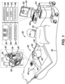
- FIG. 1 is a schematic, pictorial illustration of a medical system 20 including a medical probe 22 and a control console 24, in accordance with an embodiment of the present invention.
- Medical system 20 may be based, for example, on the CARTO ® system, produced by Biosense Webster Inc. of 31 Technology Drive, Suite 200, Irvine, CA 92618 USA.
- medical probe 22 can be used for diagnostic or therapeutic treatment, such as for performing ablation procedures in a heart 26 of a patient 28.
- medical probe 22 may be used, mutatis mutandis, for other therapeutic and/or diagnostic purposes in the heart or in other body organs.
- Medical probe 22 includes a flexible tubular shaft 30 and a handle 32 coupled to a proximal end of the tubular shaft.
- a medical professional 34 can insert probe 22 through the vascular system of patient 28 so that a distal end 36 of the medical probe enters a body cavity such as a chamber of heart 26.
- medical professional 34 can deploy a basket assembly 38 affixed to distal end 36.
- Basket assembly 38 can include a plurality of electrodes 40 affixed to a plurality of spines, as described in the description referencing FIGs. 2A and 2B hereinbelow.
- medical professional 34 can manipulate handle 32 to position distal end 36 so that electrodes 40 engage cardiac tissue at a desired location or locations. Upon positioning the distal end 36 so that electrodes 40 can engage cardiac tissue, the medical professional 34 can activate the medical probe 22 such that electrical pulses are delivered by the electrodes 40 to perform the IRE ablation.
- IRE irreversible electroporation
- control console 24 is connected, by a cable 42, to body surface electrodes, which typically include adhesive skin patches 44 that are affixed to patient 28.
- Control console 24 includes a processor 46 that, in conjunction with a tracking module 48, determines location coordinates of distal end 36 inside heart 26. Location coordinates can be determined based on electromagnetic position sensor output signals provided from the distal portion of the catheter when in the presence of a generated magnetic field. Location coordinates can additionally, or alternatively be based on impedances and/or currents measured between adhesive skin patches 44 and electrodes 40 that are affixed to basket assembly 38. In addition to being used as location sensors during a medical procedure, electrodes 40 may perform other tasks such as ablating tissue in the heart.
- processor 46 may determine location coordinates of distal end 36 inside heart 26 based on impedances and/or currents measured between adhesive skin patches 44 and electrodes 40. Such a determination is typically after a calibration process relating the impedances or currents to known locations of the distal end has been performed. While embodiments presented herein describe electrodes 40 that are (also) configured to deliver IRE ablation energy to tissue in heart 26, configuring electrodes 40 to deliver any other type of ablation energy to tissue in any body cavity is considered to be within the spirit and scope of the present invention.
- Electrodes 40 that are configured to deliver IRE ablation energy to tissue in the heart 26
- the disclosed technology can be applicable to electrodes used for mapping and/or determining various characteristics of an organ or other part of the patient's 28 body.
- Processor 46 may include real-time noise reduction circuitry 50 typically configured as a field programmable gate array (FPGA), followed by an analog-to-digital (A/D) signal conversion integrated circuit 52.
- the processor can be programmed to perform one or more algorithms and uses circuitry 50 and circuit 52 as well as features of modules to enable the medical professional 34 to perform the IRE ablation procedure.
- Control console 24 also includes an input/output (I/O) communications interface 54 that enables control console 24 to transfer signals from, and/or transfer signals to electrodes 40 and adhesive skin patches 44.
- I/O input/output
- control console 24 additionally includes an IRE ablation module 56 and a switching module 58.
- IRE ablation module 56 is configured to generate IRE pulses having peak power in the range of tens of kilowatts.
- the electrodes 40 are configured to deliver electrical pulses having a peak voltage of at least 900 volts (V).
- the medical system 20 performs IRE ablation by delivering IRE pulses to electrodes 40.
- the medical system 20 delivers biphasic pulses between electrodes 40 on the spine. Additionally, or alternatively, the medical system 20 delivers monophasic pulses between at least one of the electrodes 40 and a skin patch.
- the system 20 may supply irrigation fluid (e.g., a saline solution) to distal end 36 via a channel (not shown) in tubular shaft 30.
- irrigation fluid e.g., a saline solution
- Control console 24 includes an irrigation module 60 to monitor and control irrigation parameters, such as the pressure and the temperature of the irrigation fluid.
- processor 46 can generate an electroanatomical map 62 that shows the location of distal end 36 in the patient's body. During the procedure, processor 46 can present map 62 to medical professional 34 on a display 64, and store data representing the electroanatomical map in a memory 66.
- Memory 66 may include any suitable volatile and/or non-volatile memory, such as random-access memory or a hard disk drive.
- medical professional 34 can manipulate map 62 using one or more input devices 68.
- display 64 may include a touchscreen that can be configured to accept inputs from medical professional 34, in addition to presenting map 62.
- FIG. 2A is a schematic pictorial illustration showing a perspective view of a medical probe 22 having a basket assembly 38 in an expanded form when unconstrained, such as by being advanced out of a tubular shaft lumen 80 at a distal end 36 of a tubular shaft 30.
- FIG. 2B shows the basket assembly in a collapsed form within tubular shaft 30.
- the spines 214 bow radially outwardly and in the collapsed form ( FIG. 2B ) the spines are arranged generally along a longitudinal axis 86 of tubular shaft 30.
- basket assembly 38 includes a plurality of flexible spines 214 that are formed at the end of a tubular shaft 84 and are connected at both ends.
- medical professional 34 can deploy basket assembly 38 by extending tubular shaft 84 from tubular shaft 30 causing the basket assembly 38 to exit the tubular shaft and transition to the expanded form.
- Spines 214 may have elliptical (e.g., circular) or rectangular (that may appear to be flat) cross-sections, and include a flexible, resilient material (e.g., a shape-memory alloy such as nickel-titanium, also known as Nitinol) forming a strut as will be described in greater detail herein.
- a shape-memory alloy such as nickel-titanium, also known as Nitinol
- electrodes 40 can be configured to deliver ablation energy (RF and/or IRE) to tissue in heart 26.
- the electrodes can also be used to determine the location of basket assembly 38 and/or to measure a physiological property such as local surface electrical potentials at respective locations on tissue in heart 26.
- the electrodes 40 can be biased such that a greater portion of the electrode 40 faces outwardly from the basket assembly 39 such that the electrodes 40 deliver a greater amount of electrical energy outwardly away from the basket assembly 38 (i.e., toward the heart 26 tissue) than inwardly toward the basket catheter 38.
- Examples of materials ideally suited for forming electrodes 40 include gold, platinum, and palladium (and their respective alloys). These materials also have high thermal conductivity which allows the minimal heat generated on the tissue (i.e., by the ablation energy delivered to the tissue) to be conducted through the electrodes to the back side of the electrodes (i.e., the portions of the electrodes on the inner sides of the spines), and then to the blood pool in heart 26.
- Basket assembly 38 has a distal end 94 and includes a stem 96 that extends longitudinally from a distal end 36 of shaft 84 towards distal end 94 of basket assembly 38.
- control console 24 includes irrigation module 60 that delivers irrigation fluid to distal end 36.
- Stem 96 includes multiple spray ports 98, wherein each given spray port 98 can be angled to aim delivery of the irrigation fluid to either a given electrode 40 or to tissue in heart 26.
- electrodes 40 do not include spray ports that deliver irrigation fluid, the configuration described hereinabove enables heat to be transferred from the tissue (i.e., during an ablation procedure) to the portion of the electrodes 40 on the inner side of the spines 214, and the electrodes 40 can be cooled by aiming the irrigation fluid, via spray ports 98, at the portion of the electrodes 40 on the inner side of the spines 214.
- FIGs. 3A and 3B are schematic pictorial illustrations showing exploded views of a tubular shaft 84 and spines 214 of the basket assembly 38 to provide one example of how the spines 214 can be assembled together with the tubular shaft 84, in accordance with an embodiment of the present invention.
- the spines 214 can form a spine assembly 210.
- the spines 214 can be formed from a single sheet of planar material to form a generally star shape.
- the spines 214 can be formed from the single sheet of planar material such that the spines 214 converge toward a central intersection 211.
- the intersection 211 can be a solid piece of material (as shown in FIG. 3A ) or include one or more apertures (as shown in FIG. 3B ).
- the spines 214 can be folded or otherwise bent such that a proximal end 216 of the spines 214 can be inserted into the distal end 85 of the tubular shaft 84 as shown in FIG. 3B .
- the electrodes 40 can be attached to the spines 214 before the spines are inserted into the tubular shaft 84 to form the basket assembly 38.
- the spines 214 can include a flexible, resilient material (e.g., a shape-memory alloy such as nickel-titanium, also known as Nitinol) that can enable the basket assembly 38 to transition from its collapsed form (as shown in FIG. 2B ) to its expanded form (as shown in FIG. 2A ) when the basket assembly 38 is deployed from tubular shaft 30.
- the spine 214 can be electrically isolated from the electrode 40 to prevent arcing from the electrode 40 to the spine 214.
- the basket assembly 38 shown in FIGs. 2A-3B having spines 214 formed from a single sheet of planar material and converging at a central intersection is offered merely for illustrative purposes and the disclosed technology can be applicable to other configurations of basket assemblies 38.
- the disclosed technology can be applicable to basket assemblies 38 formed from a single spine 214 or multiple spines 214 with each spine 214 being attached at both ends.
- the basket assembly 38 can include a central hub connecting the multiple spines 214 together at a distal end 94 of the basket assembly 38.
- the basket assembly 38 can include a single spine 214 configured to form a spiral, multiple spines 214 configured to form a spiral, multiple spines 214 configured to form a tripod or multiple tripods, or any other shape of basket assembly 38.
- FIGs. 2A-3B illustrate a specific configuration of basket assembly 38, the disclosed technology should not be construed as so limited.
- the spine assembly 210 can be formed by laser cutting a cylindrical hollow stock material whereby the laser is mounted for rotation about the longitudinal axis (and translation thereto) of the cylindrical stock while cutting.
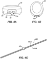
- FIGs. 4A and 4B are schematic pictorial illustrations showing perspective views of an electrode 40 while FIG. 4C is a schematic pictorial illustration showing a perspective view of an electrode 40 and a strut 430 of a given medical probe 22, in accordance with an embodiment of the present invention.
- the electrode 40 includes a lumen 70 which extends through the electrode 40 from a first end to a second end of the electrode 40.
- the electrode 40 can have an outer surface 74 facing outwardly from the electrode 40 and an inner surface 76 facing inwardly toward the electrode 40 where the lumen 70 is formed through the electrode 40.
- the lumen 70 can be sized and configured to receive a strut 430, as shown in FIG. 4C , such that the strut 430 can pass through the lumen 70.
- the lumen 70 can pass through the electrode 40 in a generally longitudinal direction of the electrode 40. In other examples, the lumen 70 can pass through the electrode 40 in a generally transverse direction of the electrode 40. Furthermore, the lumen 70 can be positioned in the electrode 40 nearer a bottom surface, nearer at top surface, or nearer a middle of the electrode 40 depending on the particular configuration.
- the disclosed technology can ensure the electrodes 40 are secured to the spines 214 and prevented from breaking free. Thus, even if the electrodes 40 become dislodged, the electrodes 40 will remain attached to the spines 214 by nature of the strut 430 passing through the lumen 70.
- the lumen 70 can further include a relief 72 forming a recess or depression in the electrode 40.
- the relief 72 can be sized to provide room for a wire of the electrode 40 to pass through the electrode 40 such that the electrode 40 can be in electrical communication with the control console 24.
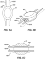
- FIGs. 5A and 5B are schematic pictorial illustrations showing perspective detailed views of an electrode 40 and struts 430 of a given medical probe while FIG. 5C is a schematic pictorial illustration showing a cutaway view of the electrode 40 and struts 430 taken along line A-A of FIG. 5B , in accordance with an embodiment of the present invention.
- the strut 430 can include a mechanical retainer that can prevent the electrode 40 from sliding proximally or distally along a length of the strut 430 and, ultimately, the spine 214.
- the spine 214 can be sized to form an interference fitting between the spine 214 and the lumen 70 of the electrode to prevent the electrode 40 from sliding proximally or distally along a length of the strut 430.
- the strut can include features that can prevent the electrode 40 from sliding proximally or distally along a length of the strut 430.
- the mechanical retainer can include one or more protrusions 532 extending outwardly from the strut 430.
- the protrusions 532 can extend outwardly from the strut 430 such that the width of the strut 430 when taken from an outer edge of one protrusion 532 to an outer edge of an opposing protrusion 532 is greater than a width of the rest of the strut 430 and greater than a width of the lumen 70.
- the electrode 40 is prevented from sliding proximally or distally along the length of the strut 430 because the electrode 40 is unable to slide past the protrusions 532.
- the strut 430 can include two halves forming a first strut 431A and a second strut 431B.
- the first and second struts 431A, 431B can be spaced apart from each other.
- the strut 430 is made from a flexible resilient material, the strut 430 can be configured such that the first and second struts 431A, 431B can be pushed toward each other to cause a width of the strut 430 to be reduced. In this way, the strut 430 along with the protrusions 532 can be configured to pass through the lumen 70.
- the protrusions 532 can be brought closer to each other such that the width of the strut 430 when taken from the outer edge of one protrusion 532 to the outer edge of the opposing protrusion 532 can be smaller than the width of the lumen 70.
- the first and second struts 431A, 431B can revert back to their normal position and the width of the strut 430 from the outer edge of one protrusion 532 to the outer edge of the opposing protrusion 532 can once again be greater than the width of the lumen 70.
- the electrode 40 can be positioned between the protrusions 532 such that the electrode 40 is prevented from sliding distally and radially along a length of the strut 430 when the first and second struts 431A, 431B are released.
- the protrusions 532 can also be angled so that as the electrode 40 is moved over the strut 430, and over the angled portions of the protrusions 532, the first and second struts 431A, 431B move toward each other.
- the first and second struts 431A, 431B can resiliently move apart once the electrode 40 is over the protrusions 532.
- the electrode is ultimately positioned between proximal and distal protrusions 532 and secured in place.
- FIGs. 6A and 6B are schematic pictorial illustrations showing perspective detailed views of an electrode 40 and a strut 630 of a given medical probe 22, in accordance with another embodiment of the present invention.
- the strut 630 does not include a first strut 431A or a second strut 431B. Rather, the strut 630 includes a single strut 630 and one or more deflectable protrusions 632.
- the deflectable protrusions 632 can be configured to be deflected toward the strut 630 when the deflectable protrusions 632 contact the electrode 40.
- the deflectable protrusions 632 can be arranged such that the deflectable protrusions 632 allow the electrode 40 to slide over the deflectable protrusions 632 in a first direction but prevent the electrode 40 from sliding over the deflectable protrusions 632 in a second direction. To illustrate, as shown in FIGs.
- the deflectable protrusions 632 can be configured such that the electrode 40 can slide along the strut 630, contact a sloped edge of the deflectable protrusions 632, and then be slid over the deflectable protrusions 632 as the deflectable protrusions 632 bend toward the strut 630. Once positioned between the deflectable protrusions 632, the electrode 40 can be prevented from sliding proximally or distally along the length of the strut 630 because the deflectable protrusions 632 are configured to prevent the electrode 40 from sliding back over the deflectable protrusions 632.
- FIGs. 6A-6C show a particular configuration of deflectable protrusions
- the deflectable protrusions 632 may include a cutaway portion of the strut 630 to allow for the deflectable protrusions 632 to be pushed flush with an outer edge of the strut 630 when the electrode 40 is slid onto the strut 630.
- the deflectable protrusions may include a spring biased component to cause the deflectable protrusions 632 to return to position after having been deflected by contacting the electrode 40 as the electrode 40 is pushed onto the strut 630.
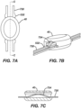
- FIGs. 7A and 7B are schematic pictorial illustrations showing perspective detailed views of an electrode 40 and struts 730 of a given medical probe 22 while FIG. 7C is a schematic pictorial illustration showing a cutaway view of the electrode 40 and struts 730 taken along line C-C of FIG. 7A , in accordance with another embodiment of the present invention.
- the mechanical retainer of the strut 730 can include a bend 734 forming a spring bias in the strut 730.
- the bend 734 can cause the strut 730 to form a friction fit with the inner surface 76 of the electrode 40 (e.g., at a top and a bottom of the lumen 70).
- the bend 734 can cause the strut 730 to contact, or otherwise cause a portion of the spine 214 to contact, the inner surface 76 of the electrode 40 and be retained in place by the friction interference between the strut 730 (or the spine 214) and the inner surface 76 of the electrode 40.
- the strut 730 can help prevent the electrode 40 from sliding distally or proximally along the length of the strut 730 as a result of the friction present at the friction fit location between the strut 730 and the electrode 40.
- the bend 734 can be sized to extend from proximate a first end of the electrode 40 to proximate a second end of the electrode 40.
- the electrode 40 can also have a recess (not illustrated) to accept the bend 734 to allow it to be properly placed on the strut 730.
- the strut 730 can further include protrusions 532 similar to strut 430 to help prevent the electrode 40 from sliding proximally or distally along the length of the strut 730.
- protrusions 532 similar to strut 430 to help prevent the electrode 40 from sliding proximally or distally along the length of the strut 730.
- FIGs. 7A-7C as having a strut with two portions (i.e., first strut 431A and second strut 431B) and protrusions 532 similar to strut 430, one of skilled in the art will appreciate that the strut 730 can include a single strut and deflectable protrusion 632 similar to strut 630.
- FIGs. 8A and 8B are schematic pictorial illustrations showing perspective detailed views of an electrode 40 and struts 830 of a given medical probe while FIG. 8C is a schematic pictorial illustration showing a cutaway view of the electrode and struts taken along line D-D of FIG. 8A , in accordance with another embodiment of the present invention.
- strut 830 can include a bend 834 forming a spring bias in the strut 830 to help prevent the electrode 40 from sliding proximally or distally along the length of the strut 830.
- the bend 834 in the strut 830 can extend from beyond a first end of the electrode 40 to beyond a second end of the electrode.
- the bend 834 can cause the strut 830, or the spine 214, to contact the inner surface of the electrode 76 of the electrode 40 as well as an outer edge of the electrode 40.
- the strut 830 can prevent the electrode 40 from sliding proximally or distally along the length of the strut 830 without including protrusions 532 or deflectable protrusions 632.
- the strut 830 can also include the protrusions 532 or deflectable protrusions 632.
- first strut 431A and second strut 431B can include a single strut similar to strut 630.
- the strut 430 (or strut 630, 730, or 830) can include a combination of several of the features of the mechanical retainers described herein.
- the medical probe 22 can include a strut 930 having a first strut 931A, a second strut 931B, and a third strut 931C.
- the first and second struts 931A, B can be configured substantially similar to the first and second struts 431A, 431B shown and described here in relation to FIGS. 4C-5C while the third strut 931C can include a bend 934 that can be substantially similar to the bend 734 or the bend 834.
- the third strut 931C including the bend 934 can be positioned between the first and second struts 931A, B.
- the electrode 40 can be better prevented from sliding distally or proximally along the length of the spine 214.
- FIGs. 10A-10F are schematic pictorial illustrations showing various electrodes 1040A-F of a given medical device 22, in accordance with various embodiments of the present invention.
- the electrodes 1040A-F are offered to illustrate various configurations of electrodes 40 that can be used with the medical device 22 but should not be construed as limiting.
- One skilled in the art will appreciate that various other configurations of electrodes 40 can be used with the disclosed technology without departing from the scope of this disclosure.
- FIGs. 10A and 10B illustrate an electrode 1040A having a lumen 1070 with a relief 1072.
- the lumen 1070 and the relief 1072 can be substantially similar to the lumen 70 and the relief 72 described herein.
- the electrode 1040A can include a substantially contoured shape.
- the electrode 1040A can include a convex side and a concave side.
- the electrode 1040A can be configured to position the convex side to face outwardly from the basket assembly 38 when the electrode 1040A is attached to a spine 214 and assembled with the basket assembly 38.
- FIGs. 10C and 10D illustrate an electrode 1040B having a lumen 1070.
- the lumen 1070 can be substantially similar to the lumen 70 described herein.
- the electrode 1072B can include a second lumen 1073 that is separate from the lumen 1070 and that can extend from a first side to a second side of the electrode 1070B.
- the second lumen 1073 can be configured to receive a wire of the medical probe 22, similar to the relief 72.
- electrode 1040B can have a substantially contoured shape.
- the electrode 1040B can include a convex side and a concave side.
- the electrode 1040B can be configured to position the convex side to face outwardly from the basket assembly 38 when the electrode 1040B is attached to a spine 214 and assembled with the basket assembly 38.
- FIGs. 10E and 10F illustrate another example electrode 1040C having a lumen 1070 and a second lumen 1073, similar to electrode 1040B.
- the electrode 1040C can be shaped such that an upper side of the electrode 1040C includes substantially more material than a lower side of the electrode 1040C. In this way, a greater portion of the electrode 1040C can be positioned toward an outer side of the basket assembly 38 when the electrode 1040C is attached to a spine 214 and assembled with the basket assembly 38.
- FIGs. 11A and 11B are schematic pictorial illustrations showing various insulative jackets 1180A, 1180B of a given medical device 22, in accordance with embodiments of the present invention.
- the insulative jackets 1180A, 1180B are offered for illustrative purposes and other insulative coverings are contemplated.
- an insulative coating can be applied to the spine 214, the electrodes 40, or both.
- FIG. 11A is a front view while FIG. 11B is a perspective view of the insulative jackets 1180A, 1180B.
- the insulative jackets 1180A, 1180B can be made from a biocompatible, electrically insulative material such as such as polyamide-polyether (Pebax) copolymers, polyethylene terephthalate (PET), urethanes, polyimide, parylene, silicone, etc.
- a biocompatible, electrically insulative material such as such as polyamide-polyether (Pebax) copolymers, polyethylene terephthalate (PET), urethanes, polyimide, parylene, silicone, etc.
- insulative material can include biocompatible polymers including, without limitation, polyetheretherketone (PEEK), polyglycolic acid (PGA), poly(lactic-co-glycolic acid) copolymer (PLGA), polycaprolactive (PCL), poly(3-hydroxybutyrate-co-3-hydroxyvalerate) (PHBV), poly-L-lactide, polydioxanone, polycarbonates, and polyanhydrides with the ratio of certain polymers being selected to control the degree of inflammatory response.
- PEEK polyetheretherketone
- PGA polyglycolic acid
- PLGA poly(lactic-co-glycolic acid) copolymer
- PCL polycaprolactive
- PHBV poly(3-hydroxybutyrate-co-3-hydroxyvalerate)
- poly-L-lactide polydioxanone
- polycarbonates polyanhydrides with the ratio of certain polymers being selected to control the degree of inflammatory response.
- Insulative jackets 1180A, 1180B may also include one or more additives or fillers, such as, for example, polytetrafluoroethylene (PTFE), boron nitride, silicon nitride, silicon carbide, aluminum oxide, aluminum nitride, zinc oxide, and the like.
- PTFE polytetrafluoroethylene
- the insulative jacket 1180A, 1180B can help to insulate a strut and/or wires passing through the insulative jacket 1180A, 1180B from the electrode 40 to prevent arcing from the electrode 40 to the strut and/or wires passing through the insulative jacket 1180A, 1180B.
- the insulative jacket 1180A, 1180B can include a cross-sectional shape that is substantially trapezoidal.
- the insulative jacket may consist of a single lumen or multi-lumen configuration. Multi-lumen jackets may be configured such that the alloy frame and wires share a single lumen while the second lumen may be used for irrigation.
- the alloy frame and wires may occupy separate lumens, also, as described.
- the insulative jackets may be continuous (individual sleeves extending from proximal to distal end of each alloy frame strut), segmented (bridging between electrode gaps), or a combination of both.
- the insulative jacket 1180A, 1180B can include a first lumen 1182A, 1182B and a second lumen 1184A, 1184B.
- the first lumen 1182A, 1182B can be configured to receive a strut while the second lumen 1184A, 1184B can be configured to receive a wire, or vice-versa.
- the first lumen 1182A, 1182B and the second lumen 1184A, 1184B can each be configured to receive one or more wires that can be connected to one or more electrodes 40.
- the insulative jacket 1180A, 1180B can include an aperture 1186A, 1186B through which a wire can be electrically connected to the electrode 40.
- the aperture 1186A, 1186B can be positioned proximate a top or side of the insulative jacket 1180A, 1180B.
- the insulative jacket 1180A, 1180B can include multiple apertures 1186A, 1186B with each aperture being disposed on the same side of the insulative jacket (i.e., top, bottom, left, right) or on different sides of the insulative jacket depending on the application.
- FIGs. 12A and 12B are schematic pictorial illustrations showing a side view of a spine 214 of a given medical device 22, in accordance with embodiments of the present invention.
- the spine 214 illustrated in FIGS. 12A and 12B is a single spine 214 and can be representative of the plurality of spines 214 of the basket assembly 38 described herein.
- the plurality of spines 214 forming the basket assembly 38 can each be configured to form the same or similar shape when in the expanded form such that the plurality of spines 214 together form a desired shape.
- the spine 214 as shown in FIG. 12A can be configured to form an approximately circular shape when in the expanded form.
- the plurality of spines 214 when combined with other spines 214 to form the basket assembly 38, can be configured to form an approximately spherical shape when the basket assembly 38 is in the expanded form.
- the spine 214 shown in FIG. 12B can be configured to form an approximately elliptical shape when in the expanded form.
- the plurality of spines 214 when combined with other spines 214 to form the basket assembly 38, can be configured to form an approximately oblate-spheroid shape when the basket assembly 38 is in the expanded form.
- the spines 214 can be further configured to form other various shapes as would be suitable for the particular application.
- the basket assembly 38 can be configured to position the various electrodes 40 attached to the spines 214 at various locations, with each location being nearer or farther from the distal end of the flexible tubular shaft 30.
- an electrode 40 attached to the spine 214 illustrated in FIG. 12A near the middle of the spine 214 would be farther from the distal end of the flexible tubular shaft 30 than the spine 214 illustrated in FIG. 12B when the basket assembly 38 is in the expanded form.
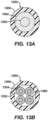
- FIGs. 13A and 13B are schematic pictorial illustrations showing cross-sectional views of a given wire 1300, 1350 that can be connected to a given electrode 40, in accordance with an embodiment of the present invention.
- FIG. 13A illustrates a solid core wire 1300.
- FIG. 13B illustrates a stranded wire 1350.
- Each wire 1300, 1350 can extend through at least a portion of the tubular shaft 84.
- the solid core wire 1300 can include an electrically conductive core material 1302 and an electrically conductive cover material 1304 circumscribing electrically conductive core material 1302.
- the stranded wire 1350 can include strands each including an electrically conductive core material 1352 and an electrically conductive cover material 1354 circumscribing the electrically conductive core material 1352.
- Each wire 1300, 1350 can include an insulative jacket 1306 circumscribing the conductors.
- the wires 1300, 1350 can be configured to withstand a voltage difference of adjacent wires sufficient to deliver IRE pulses.
- the wires 1300, 1350 can withstand at least 900V, and more preferably at least 1,800V between adjacent wires.
- the electrically conductive cover material 1304, 1354 can have a lower electrical conductivity compared to the core material 1302, 1352.
- the insulative jacket 1306 can be configured to have a temperature rating between 150 and 200 degrees Centigrade so that the electrically insulative jacket 1306 melts or degrades (e.g., chars and crumbles) during soldering of the wire 1300 to the electrodes 40 (e.g., at a temperature of 300 degrees Centigrade) and therefore the insulative jacket 1306 of the wire 1300 does not need to be mechanically stripped.
- the insulative jacket 1306 can have a temperature rating greater than 200 degrees Centigrade to prevent the electrically insulating material 1302 melting or degrading (e.g., charring and crumbling) during manufacture of the medical probe 22 and/or during use.
- the insulative jacket 1306 can be mechanically stripped from the wire 1300 prior to the wires 1300 being electrically connected to the electrodes 40.
- FIG. 14 is a flowchart illustrating a method 1400 of manufacturing a basket assembly 38, in accordance with an embodiment of the present invention.
- the method 1400 can include aligning 1402 a spine 214 of an expandable basket assembly 38 with an electrode 40 (or electrode 1040A-1040C).
- aligning 1402 a spine 214 with an electrode 40 can include aligning a distal or a proximal end of a spine 214 with the lumen 70 of the electrode 40.
- the spine 214 can include any of struts 430, 630, 730, 830, 930 as shown and described herein.
- the method 1400 can further include inserting 1404 the spine 214 into the lumen 70 of the electrode 40 and pushing 1406 the spine into the lumen 70 of the electrode 40 until a mechanical retainer (i.e., protrusions 532, deflectable protrusions 632, bend 734, and/or bend 834) engages with the electrode 40.
- a mechanical retainer i.e., protrusions 532, deflectable protrusions 632, bend 734, and/or bend 834 engages with the electrode 40.
- the method 1400 can include any of the various features of the disclosed technology described herein and can be varied depending on the particular configuration.
- the method 1400 can further include positioning the bend 734 bend to extend from proximate a first end of the electrode 40 to proximate a second end of the electrode 40 to cause the strut 730 to form a friction fit with a first portion and a second portion of an inner surface 76 of the electrode 40 (as described herein).
- the method 1400 can further include positioning the bend 834 to extend from a first distance beyond a first end of the electrode 40 to a second distance beyond a second end of the electrode 40 to cause the strut 830 to form a friction fit with an inner surface 76 of the electrode 40 and an outer edge of the electrode (e.g., outer surface 74).
- the method 1400 can include aligning 1402 the spine with a second electrode 40 (or electrode 1040A-1040C), inserting 1404 the spine 214 into the second electrode 40, and pushing the spine 214 into the lumen 70 of the second electrode 40 until the mechanical retainer (i.e., protrusions 532, deflectable protrusions 632, bend 734, and/or bend 834) engages with the electrode 40.
- the method 1400 can include attaching more than one electrode 40 to the spine 214 to form a basket assembly 38 having multiple electrodes 40.
Landscapes
- Health & Medical Sciences (AREA)
- Life Sciences & Earth Sciences (AREA)
- Surgery (AREA)
- Engineering & Computer Science (AREA)
- Animal Behavior & Ethology (AREA)
- Veterinary Medicine (AREA)
- Biomedical Technology (AREA)
- Heart & Thoracic Surgery (AREA)
- Medical Informatics (AREA)
- Molecular Biology (AREA)
- Physics & Mathematics (AREA)
- Public Health (AREA)
- General Health & Medical Sciences (AREA)
- Cardiology (AREA)
- Plasma & Fusion (AREA)
- Nuclear Medicine, Radiotherapy & Molecular Imaging (AREA)
- Otolaryngology (AREA)
- Pathology (AREA)
- Biophysics (AREA)
- Physiology (AREA)
- Surgical Instruments (AREA)
- Electrical Discharge Machining, Electrochemical Machining, And Combined Machining (AREA)
Abstract
Description
- This application claims the benefit of priority under 35 U.S.C. § 119 to prior filed
U.S. Provisional Patent Application No. 63/301,142 - The present invention relates generally to medical devices, and in particular catheters with electrodes, and further relates to, but not exclusively, catheters suitable for use to induce irreversible electroporation (IRE) of cardiac tissues.
- Cardiac arrhythmias, such as atrial fibrillation (AF), occur when regions of cardiac tissue abnormally conduct electric signals to adjacent tissue. This disrupts the normal cardiac cycle and causes asynchronous rhythm. Certain procedures exist for treating arrhythmia, including surgically disrupting the origin of the signals causing the arrhythmia and disrupting the conducting pathway for such signals. By selectively ablating cardiac tissue by application of energy via a catheter, it is sometimes possible to cease or modify the propagation of unwanted electrical signals from one portion of the heart to another.
- Many current ablation approaches in the art utilize radiofrequency (RF) electrical energy to heat tissue. RF ablation can have certain risks related to thermal heating which can lead to tissue charring, burning, steam pop, phrenic nerve palsy, pulmonary vein stenosis, and esophageal fistula.
- Cryoablation is an alternative approach to RF ablation that generally reduces thermal risks associated with RF ablation. Maneuvering cryoablation devices and selectively applying cryoablation, however, is generally more challenging compared to RF ablation; therefore cryoablation is not viable in certain anatomical geometries which may be reached by electrical ablation devices.
- Some ablation approaches use irreversible electroporation (IRE) to ablate cardiac tissue using nonthermal ablation methods. IRE delivers short pulses of high voltage to tissues and generates an unrecoverable permeabilization of cell membranes. Delivery of IRE energy to tissues using multi-electrode catheters was previously proposed in the patent literature. Examples of systems and devices configured for IRE ablation are disclosed in
U.S. Patent Pub. No. 2021/0169550A1 ,2021/0169567A1 ,2021/0169568A1 ,2021/0161592A1 ,2021/0196372A1 ,2021/0177503A1 , and2021/0186604A1 , each of which are incorporated by reference in their entirety into this application as if set forth in full and attached in the appendix to priority applicationU.S. 63/301,142 - Regions of cardiac tissue can be mapped by a catheter to identify the abnormal electrical signals. The same or different catheter can be used to perform ablation. Some example catheters include a number of spines with electrodes positioned thereon. The electrodes are generally attached to the spines and secured in place by soldering, welding, or using an adhesive. Due to the small size of the spines and the electrodes, however, soldering, welding, or adhering the electrodes to the spines can be a difficult task, increasing the manufacturing time and cost and the chances that the electrode fails due to an improper bond or misalignment. What is needed, therefore, are systems and methods of attaching an electrode to a spine of a basket assembly without the need for soldering, welding, or using adhesive.
- There is provided, in accordance with an embodiment of the present invention, a medical probe, including a plurality of spines having electrodes disposed thereon. The spines of the medical probe each include a strut having a mechanical retainer and the electrodes each includes a lumen therethrough. The strut can be inserted into the lumen of the electrode and the mechanical retainer of the strut can engage with the electrode and prevent the electrode from sliding proximally or distally along a length of the spine. In this way, the presently disclosed technology can be used to secure the electrodes to the spines without requiring solder, weld, or adhesives.
- The disclosed technology includes a medical probe including a tubular shaft having a proximal end and a distal end and an expandable basket assembly coupled to the distal end of the tubular shaft. The tubular shaft can extend along a longitudinal axis.
- The expandable basket assembly can include a plurality of electrodes. Each electrode can include a lumen therethrough. The expandable basket assembly can further include a plurality of spines extending along the longitudinal axis and configured to bow radially outward from the longitudinal axis when the expandable basket assembly is transitioned from a collapsed form to an expanded form.
- Each spine of the plurality of spines can include a proximal end, a distal end, and a strut passing through the lumen of an electrode of the plurality of electrodes. The strut can include a mechanical retainer disposed on the strut that can prevent the electrode from sliding proximally or distally along a length of the spine.
- The mechanical retainer of the strut can include one or more protrusions extending outwardly from the strut to form a lip that prevents the electrode from sliding proximally or distally along the length of the spine. The strut can include a first and a second strut each including a respective protrusion of the one or more protrusions. The first and second struts can be configured to be compressible toward each other to allow the respective protrusions to slide through the lumen of the electrode. The first and second struts each can include a respective pair of protrusions of the one or more protrusions. Each pair of protrusions can include a first protrusion positioned on a first side of the electrode and a second protrusion positioned on a second side of the electrode such that each pair of protrusions prevent the electrode from sliding proximally or distally along the length of the spine.
- The mechanical retainer of the strut can include a bend forming a spring bias in the strut to cause the strut to form a friction fit with the electrode and prevent the electrode from sliding proximally or distally along the length of the spine. The bend can extend from proximate a first end of the electrode to proximate a second end of the electrode to cause the strut to form a friction fit at a first portion and a second portion of an inner surface of the electrode. Alternatively, the bend can extend from a first distance beyond a first end of the electrode to a second distance beyond a second end of the electrode to cause the strut to form a friction fit at an inner surface of the electrode and an outer edge of the electrode.
- The strut can include a first and a second strut each including a respective protrusion. The first and second struts can be configured to be compressible toward each other to allow the respective protrusions to slide through the lumen of the electrode. The first and second struts can further include a bend.
- The strut can include a first strut, a second strut, and a third strut positioned between the first and second struts. The first and second struts can each include a respective protrusion and be compressible toward each other to allow the respective protrusions to slide through the lumen of the electrode and third strut can include the bend.
- The spine of the plurality of spines can include a first electrode and a second electrode and the strut can include a first mechanical retainer configured to engage with the first electrode and a second mechanical retainer configured to engage with the second electrode. The first and second mechanical retainers can be configured to prevent the first and second electrodes from sliding proximally or distally along a length of the spine when the first and second mechanical retainers are engaged with the first and second electrodes, respectively.
- The mechanical retainer(s) of the strut can include an interference fitting.
- The medical probe can further include a wire and the lumen can include a relief configured to receive the wire of the medical probe. The wire can be insulated from the strut and electrically connected to the electrode. At least a portion of the wire can include an electrically conductive core material having a first electrical conductivity, an electrically conductive cover material having a second electrical conductivity less than the first electrical conductivity. The electrically conductive cover material can circumscribe the electrically conductive core material. The wire can also include an insulative jacket circumscribing the electrically conductive cover material. At least a portion of the wire can include a plurality of strands and an insulative jacket circumscribing the plurality of strands. Each strand of the plurality of strands can include an electrically conductive core material having a first electrical conductivity and an electrically conductive cover material having a second electrical conductivity less than the first electrical conductivity. The electrically conductive cover material can circumscribe the electrically conductive core material.
- The strut can include a material selected from a group consisting of nitinol, cobalt chromium, stainless steel, titanium. Alternatively, or in addition, the strut can include a polymer.
- The electrode can include a ring type electrode, a bulging type electrode, or a rectangular electrode. The plurality of electrodes can be configured to deliver electrical pulses for irreversible electroporation, the pulses having a peak voltage of at least 900 volts (V).
- The plurality of spines can be configured to form an approximately spherically-shaped basket assembly or an approximately oblate-spheroid basket assembly when in the expanded form.
- The medical probe can further include spray ports that can be configured to deliver an irrigation fluid to the plurality of electrodes.
- The medical probe can further include a plurality of electrically insulative jackets each disposed between a respective spine of the plurality of spines and a respective electrode of the plurality of electrodes, thereby electrically isolating the plurality of electrodes from the plurality of spines. Each of the electrically insulative jackets of the plurality of electrically insulative jackets can include a first lumen and a second lumen. The first lumen can be configured to receive a first wire and the second lumen can be configured to receive the respective spine. Furthermore, a cross-sectional shape of each electrically insulative jacket can include a substantially trapezoidal shape.
- The disclosed technology can further include a method of constructing a medical probe. The method can include aligning a spine of an expandable basket assembly with an electrode of the expandable basket assembly. The spine can have a proximal end, a distal end, and a strut having a mechanical retainer. The method can further include inserting the spine into a lumen of the electrode and pushing the spine into the lumen of the electrode until the mechanical retainer engages with the electrode to prevent the electrode from sliding proximally or distally along a length of the spine.
- The mechanical retainer of the strut can include one or more protrusions extending outwardly from the strut to form a lip. Furthermore, pushing the spine into the lumen of the electrode until the mechanical retainer engages with the electrode can include pushing the spine into the lumen of the electrode until the lip is positioned to prevent the electrode from sliding proximally or distally along the length of the spine.
- The strut can include a first and a second strut each including a respective protrusion of the one or more protrusions. Pushing the spine into the lumen of the electrode until the mechanical retainer engages with the electrode can include pushing the spine into the lumen of the electrode to cause the first and second struts to compress toward each other to allow the respective protrusions to slide through the lumen of the electrode.
- The first and second struts can each include a respective pair of protrusions of the one or more protrusions, each pair of protrusions including a first protrusion and a second protrusion. Furthermore, pushing the spine into the lumen of the electrode until the mechanical retainer engages with the electrode includes pushing the spine into the lumen of the electrode to cause the first protrusion to be positioned on a first side of the electrode and the second protrusion to be positioned on a second side of the electrode so that the pair of protrusions prevent the electrodes from sliding proximally or distally along the length of the spine.
- The mechanical retainer of the strut can include a bend forming a spring bias in the strut. The spring bias can cause the strut to form a friction fit with the electrode and prevent the electrode from sliding along the length of the spine. Pushing the spine into the lumen of the electrode until the mechanical retainer engages with the electrode can include pushing the spine into the lumen of the electrode until the bend is positioned to prevent the electrode from sliding proximally or distally along the length of the spine.
- The method can further include positioning the bend to extend from proximate a first end of the electrode to proximate a second end of the electrode to cause the strut to form a friction fit at a first portion and a second portion of an inner surface of the electrode.
- The method can further include positioning the bend to extend from a first distance beyond a first end of the electrode to a second distance beyond a second end of the electrode to cause the strut to form a friction fit at an inner surface of the electrode and an outer edge of the electrode.
- The spine can include a first electrode and a second electrode, and the mechanical retainer includes a first mechanical retainer and a second mechanical retainer. The method can further include aligning the spine of the expandable basket assembly with the first electrode and the second electrode, inserting the spine into a lumen of the first electrode and a lumen of the second electrode, pushing the spine into the lumen of the first electrode until the first mechanical retainer engages with the first electrode to prevent the first electrode from sliding proximally or distally along a length of the spine, and pushing the spine into the lumen of the second electrode until the second mechanical retainer engages with the second electrode to prevent the second electrode from sliding proximally or distally along a length of the spine.
- The method can further include securing the mechanical retainer to the electrode by an interference fit.
- The lumen can include a relief configured to receive a wire of the medical probe. The wire can be insulated from the strut and electrically connected to the electrode.
- At least a portion of the wire can include an electrically conductive core material having a first electrical conductivity and an electrically conductive cover material having a second electrical conductivity less than the first electrical conductivity. The electrically conductive cover material can circumscribe the electrically conductive core material. The wire can further include an insulative jacket circumscribing the electrically conductive cover material.
- At least a portion of the wire can include a plurality of strands and an insulative jacket circumscribing the plurality of the strands. Each strand of the plurality of strands respectively can include an electrically conductive core material having a first electrical conductivity and an electrically conductive cover material having a second electrical conductivity less than the first electrical conductivity. The electrically conductive cover material can circumscribe the electrically conductive core material.
- The strut can include a material selected from a group consisting of nitinol, cobalt chromium, stainless steel, titanium. Alternatively, or in addition, the strut can include a polymer.
- The electrode can include a ring type electrode, a bulging type electrode, or a rectangular electrode. The method can further include configuring the electrode to deliver electrical pulses for irreversible electroporation, the pulses having a peak voltage of at least 900 volts (V).
- The method can further include configuring the plurality of spines to form an approximately spherically-shaped basket assembly or an oblate-spheroid-shaped basket assembly.
- The method can further include configuring spray ports to deliver an irrigation fluid to the electrode.
- The method can include positioning each spine of the plurality of spines through a first lumen of an electrically insulative jacket, positioning a wire through a second lumen of the electrically insulative jacket, positioning the electrode over the electrically insulative jacket, and electrically connecting the wire to the electrode through an aperture in the electrically insulative jacket providing passage between the second lumen and the electrode. A cross-sectional shape of the electrically insulative jacket can have a substantially trapezoidal shape.
-
-
FIG. 1 is a schematic pictorial illustration of a medical system including a medical probe whose distal end includes a basket assembly with electrodes, in accordance with an embodiment of the present invention; -
FIG. 2A is a schematic pictorial illustration showing a perspective view of a medical probe in an expanded form, in accordance with an embodiment of the present invention; -
FIG. 2B is a schematic pictorial illustration showing a side view of a medical probe in a collapsed form, in accordance with the disclosed technology; -
FIGs. 3A and 3B are schematic pictorial illustrations showing exploded views of a tubular shaft and spines of the basket assembly to illustrate how the spines can be assembled together with the tubular shaft, in accordance with an embodiment of the present invention; -
FIGs. 4A and 4B are schematic pictorial illustrations showing perspective views of an electrode, in accordance with an embodiment of the present invention; -
FIG. 4C is a schematic pictorial illustration showing a perspective view of an electrode and a strut of a given medical probe, in accordance with an embodiment of the present invention; -
FIGs. 5A and 5B are schematic pictorial illustrations showing perspective detailed views of an electrode and struts of a given medical probe, in accordance with an embodiment of the present invention; -
FIG. 5C is a schematic pictorial illustration showing a cutaway view of the electrode and struts taken along line A-A ofFIG. 5B , in accordance with an embodiment of the present invention; -
FIGs. 6A and 6B are schematic pictorial illustrations showing perspective detailed views of an electrode and a strut of a given medical probe, in accordance with another embodiment of the present invention; -
FIG. 6C is a schematic pictorial illustration showing a cutaway view of the electrode and strut taken along line B-B ofFIG. 6B , in accordance with an embodiment of the present invention; -
FIGs. 7A and 7B are schematic pictorial illustrations showing perspective detailed views of an electrode and struts of a given medical probe, in accordance with another embodiment of the present invention; -
FIG. 7C is a schematic pictorial illustration showing a cutaway view of the electrode and struts taken along line C-C ofFIG. 7A , in accordance with another embodiment of the present invention; -
FIGs. 8A and 8B are schematic pictorial illustrations showing perspective detailed views of an electrode and struts of a given medical probe, in accordance with another embodiment of the present invention; -
FIG. 8C is a schematic pictorial illustration showing a cutaway view of the electrode and struts taken along line D-D ofFIG. 8A , in accordance with another embodiment of the present invention; -
FIGs. 9A and 9B are schematic pictorial illustrations showing perspective detailed views of an electrode and struts of a given medical probe, in accordance with another embodiment of the present invention; -
FIG. 9C is a schematic pictorial illustration showing a cutaway view of the electrode and struts taken along line E-E ofFIG. 9A , in accordance with another embodiment of the present invention; -
FIG. 9D is a schematic pictorial illustration showing a cutaway view of the electrode and struts taken along line F-F ofFIG. 9B , in accordance with another embodiment of the present invention; -
FIGs. 10A-10F are schematic pictorial illustrations showing various electrodes of a given medical device, in accordance with various embodiments of the present invention; -
FIGs. 11A and 11B are schematic pictorial illustrations showing various insulative jackets of a given medical device, in accordance with embodiments of the present invention; -
FIGs. 12A and 12B are schematic pictorial illustrations showing a side view of a spine of a given medical device, in accordance with embodiments of the present invention; -
FIGs. 13A and 13B are schematic pictorial illustrations showing cross-sectional views of a given wire of a medical probe, in accordance with an embodiment of the present invention; -
FIG. 14 is a flowchart illustrating a method of manufacturing a basket assembly, in accordance with an embodiment of the present invention. - The following detailed description should be read with reference to the drawings, in which like elements in different drawings are identically numbered. The drawings, which are not necessarily to scale, depict selected embodiments and are not intended to limit the scope of the invention. The detailed description illustrates by way of example, not by way of limitation, the principles of the invention. This description will clearly enable one skilled in the art to make and use the invention, and describes several embodiments, adaptations, variations, alternatives and uses of the invention, including what is presently believed to be the best mode of carrying out the invention.
- As used herein, the terms "about" or "approximately" for any numerical values or ranges indicate a suitable dimensional tolerance that allows the part or collection of components to function for its intended purpose as described herein. More specifically, "about" or "approximately" may refer to the range of values ±20% of the recited value, e.g. "about 90%" may refer to the range of values from 71% to 110%. In addition, as used herein, the terms "patient," "host," "user," and "subject" refer to any human or animal subject and are not intended to limit the systems or methods to human use, although use of the subject invention in a human patient represents a preferred embodiment. As well, the term "proximal" indicates a location closer to the operator or physician whereas "distal" indicates a location further away to the operator or physician.
- As discussed herein, vasculature of a "patient," "host," "user," and "subject" can be vasculature of a human or any animal. It should be appreciated that an animal can be a variety of any applicable type, including, but not limited thereto, mammal, veterinarian animal, livestock animal or pet type animal, etc. As an example, the animal can be a laboratory animal specifically selected to have certain characteristics similar to a human (e.g., rat, dog, pig, monkey, or the like). It should be appreciated that the subject can be any applicable human patient, for example.
- As discussed herein, "operator" can include a doctor, surgeon, technician, scientist, or any other individual or delivery instrumentation associated with delivery of a multi-electrode catheter for the treatment of drug refractory atrial fibrillation to a subject.
- As discussed herein, the term "ablate" or "ablation", as it relates to the devices and corresponding systems of this disclosure, refers to components and structural features configured to reduce or prevent the generation of erratic cardiac signals in the cells by utilizing non-thermal energy, such as irreversible electroporation (IRE), referred throughout this disclosure interchangeably as pulsed electric field (PEF) and pulsed field ablation (PFA). Ablating or ablation as it relates to the devices and corresponding systems of this disclosure is used throughout this disclosure in reference to non-thermal ablation of cardiac tissue for certain conditions including, but not limited to, arrhythmias, atrial flutter ablation, pulmonary vein isolation, supraventricular tachycardia ablation, and ventricular tachycardia ablation. The term "ablate" or "ablation" also includes known methods, devices, and systems to achieve various forms of bodily tissue ablation as understood by a person skilled in the relevant art.
- As discussed herein, the terms "bipolar" and "unipolar" when used to refer to ablation schemes describe ablation schemes which differ with respect to electrical current path and electric field distribution. "Bipolar" refers to ablation scheme utilizing a current path between two electrodes that are both positioned at a treatment site; current density and electric flux density is typically approximately equal at each of the two electrodes. "Unipolar" refers to ablation scheme utilizing a current path between two electrodes where one electrode having a high current density and high electric flux density is positioned at a treatment site, and a second electrode having comparatively lower current density and lower electric flux density is positioned remotely from the treatment site.
- As discussed herein, the terms "biphasic pulse" and "monophasic pulse" refer to respective electrical signals. "Biphasic pulse" refers to an electrical signal having a positive-voltage phase pulse (referred to herein as "positive phase") and a negative-voltage phase pulse (referred to herein as "negative phase"). "Monophasic pulse" refers to an electrical signal having only a positive or only a negative phase. Preferably, a system providing the biphasic pulse is configured to prevent application of a direct current voltage (DC) to a patient. For instance, the average voltage of the biphasic pulse can be zero volts with respect to ground or other common reference voltage. Additionally, or alternatively, the system can include a capacitor or other protective component. Where voltage amplitude of the biphasic and/or monophasic pulse is described herein, it is understood that the expressed voltage amplitude is an absolute value of the approximate peak amplitude of each of the positive-voltage phase and/or the negative-voltage phase. Each phase of the biphasic and monophasic pulse preferably has a square shape having an essentially constant voltage amplitude during a majority of the phase duration. Phases of the biphasic pulse are separated in time by an interphase delay. The interphase delay duration is preferably less than or approximately equal to the duration of a phase of the biphasic pulse. The interphase delay duration is more preferably about 25% of the duration of the phase of the biphasic pulse.
- As discussed herein, the terms "tubular" and "tube" are to be construed broadly and are not limited to a structure that is a right cylinder or strictly circumferential in cross-section or of a uniform cross-section throughout its length. For example, the tubular structures are generally illustrated as a substantially right cylindrical structure. However, the tubular structures may have a tapered or curved outer surface without departing from the scope of the present disclosure.
- The term "temperature rating", as used herein, is defined as the maximum continuous temperature that a component can withstand during its lifetime without causing thermal damage, such as melting or thermal degradation (e.g., charring and crumbling) of the component.
- The present disclosure is related to systems, method or uses and devices for IRE ablation of cardiac tissue to treat cardiac arrhythmias. Ablative energies are typically provided to cardiac tissue by a tip portion of a catheter which can deliver ablative energy alongside the tissue to be ablated. Some example catheters include three-dimensional structures at the tip portion and are configured to administer ablative energy from various electrodes positioned on the three-dimensional structures. Ablative procedures incorporating such example catheters can be visualized using fluoroscopy.
- Ablation of cardiac tissue using application of a thermal technique, such as radio frequency (RF) energy and cryoablation, to correct a malfunctioning heart is a well-known procedure. Typically, to successfully ablate using a thermal technique, cardiac electropotentials need to be measured at various locations of the myocardium. In addition, temperature measurements during ablation provide data enabling the efficacy of the ablation. Typically, for an ablation procedure using a thermal technique, the electropotentials and the temperatures are measured before, during, and after the actual ablation. RF approaches can have risks that can lead to tissue charring, burning, steam pop, phrenic nerve palsy, pulmonary vein stenosis, and esophageal fistula. Cryoablation is an alternative approach to RF ablation that can reduce some thermal risks associated with RF ablation. However maneuvering cryoablation devices and selectively applying cryoablation is generally more challenging compared to RF ablation; therefore cryoablation is not viable in certain anatomical geometries which may be reached by electrical ablation devices.
- While RF ablation and cryoablation, are based on thermal energy transfer to induce local tissue necrosis, the solution of this disclosure resolves these and other problems by utilizing irreversible electroporation (IRE), referred throughout this disclosure interchangeably as pulsed electric field (PEF) ablation and pulsed field ablation (PFA). IRE as discussed in this disclosure is a non-thermal cell death technology that can be used for ablation of atrial arrhythmias. To ablate using IRE/PEF, biphasic voltage pulses are applied to disrupt cellular structures of myocardium. The biphasic pulses are non-sinusoidal and can be tuned to target cells based on electrophysiology of the cells. In contrast, to ablate using RF, a sinusoidal voltage waveform is applied to produce heat at the treatment area, indiscriminately heating all cells in the treatment area. IRE therefore has the capability to spare adjacent heat sensitive structures or tissues which would be of benefit in the reduction of possible complications known with ablation or isolation modalities. Additionally, or alternatively, monophasic pulses can be utilized.
- Electroporation can be induced by applying a pulsed electric field across biological cells to cause reversable (temporary) or irreversible (permanent) creation of pores in the cell membrane. The cells have a transmembrane electrostatic potential that is increased above a resting potential upon application of the pulsed electric field. While the transmembrane electrostatic potential remains below a threshold potential, the electroporation is reversable, meaning the pores can close when the applied pulse electric field is removed, and the cells can self-repair and survive. If the transmembrane electrostatic potential increases beyond the threshold potential, the electroporation is irreversible, and the cells become permanently permeable. As a result, the cells die due to a loss of homeostasis and typically die by apoptosis. Generally, cells of differing types have differing threshold potential. For instance, heart cells have a threshold potential of approximately 500 V/cm, whereas for bone it is 3000 V/cm. These differences in threshold potential allow IRE to selectively target tissue based on threshold potential.
- The solution of this disclosure includes systems and methods for applying electrical signals from catheter electrodes positioned in the vicinity of myocardial tissue to generate a pulsed electric field effective to induce electroporation in the myocardial tissue. The systems and methods can be effective to ablate targeted tissue by inducing irreversible electroporation. In some examples, the systems and methods can be effective to induce reversible electroporation as part of a diagnostic procedure. Reversible electroporation occurs when the electricity applied with the electrodes is below the electric field threshold of the target tissue allowing cells to repair. Reversible electroporation does not kill the cells but allows a physician to see the effect of reversible electroporation on electrical activation signals in the vicinity of the target location. Example systems and methods for reversible electroporation is disclosed in
U.S. Patent Publication 2021/0162210 , the entirety of which is incorporated by reference in its entirety into this application as if set forth in full and attached in the appendix to priority applicationU.S. 63/301,142 - The pulsed electric field, and its effectiveness to induce reversible and/or irreversible electroporation, can be affected by physical parameters of the system and biphasic pulse parameters of the electrical signal. Physical parameters can include electrode contact area, electrode spacing, electrode geometry, etc. examples presented herein generally include physical parameters adapted to effectively induce reversible and/or irreversible electroporation. Biphasic pulse parameters of the electrical signal can include voltage amplitude, pulse duration, pulse interphase delay, inter-pulse delay, total application time, delivered energy, etc. In some examples, parameters of the electrical signal can be adjusted to induce both reversible and irreversible electroporation given the same physical parameters. Examples of various systems and methods of ablation including IRE are presented in
U.S. Patent Publications 2021/0169550A1 ,2021/0169567A1 ,2021/0169568A1 ,2021/0161592A1 ,2021/0196372A1 ,2021/0177503A1 , and2021/0186604A1 , the entireties of each of which are incorporated by reference in their entirety into this application as if set forth in full and attached in the appendix to priority applicationU.S. 63/301,142 - To deliver pulsed field ablation (PFA) in an IRE (irreversible electroporation) procedure, electrodes should contact the tissue being ablated with a sufficiently large surface area. As described hereinbelow, the medical probe includes a flexible tubular shaft having proximal and distal ends, and a basket assembly at the distal end of the flexible tubular shaft. The basket assembly includes at least one spine and a plurality of electrodes, each given electrode having a lumen therethrough fitting a given spine.
-
FIG. 1 is a schematic, pictorial illustration of amedical system 20 including amedical probe 22 and acontrol console 24, in accordance with an embodiment of the present invention.Medical system 20 may be based, for example, on the CARTO® system, produced by Biosense Webster Inc. of 31 Technology Drive, Suite 200, Irvine, CA 92618 USA. In embodiments described hereinbelow,medical probe 22 can be used for diagnostic or therapeutic treatment, such as for performing ablation procedures in aheart 26 of apatient 28. Alternatively,medical probe 22 may be used, mutatis mutandis, for other therapeutic and/or diagnostic purposes in the heart or in other body organs. -
Medical probe 22 includes a flexibletubular shaft 30 and ahandle 32 coupled to a proximal end of the tubular shaft. During a medical procedure, a medical professional 34 can insertprobe 22 through the vascular system ofpatient 28 so that adistal end 36 of the medical probe enters a body cavity such as a chamber ofheart 26. Upondistal end 36 entering the chamber ofheart 26, medical professional 34 can deploy abasket assembly 38 affixed todistal end 36.Basket assembly 38 can include a plurality ofelectrodes 40 affixed to a plurality of spines, as described in the description referencingFIGs. 2A and 2B hereinbelow. To start performing a medical procedure such as irreversible electroporation (IRE) ablation, medical professional 34 can manipulate handle 32 to positiondistal end 36 so thatelectrodes 40 engage cardiac tissue at a desired location or locations. Upon positioning thedistal end 36 so thatelectrodes 40 can engage cardiac tissue, the medical professional 34 can activate themedical probe 22 such that electrical pulses are delivered by theelectrodes 40 to perform the IRE ablation. - In the configuration shown in
FIG. 1 ,control console 24 is connected, by acable 42, to body surface electrodes, which typically includeadhesive skin patches 44 that are affixed topatient 28.Control console 24 includes aprocessor 46 that, in conjunction with atracking module 48, determines location coordinates ofdistal end 36 insideheart 26. Location coordinates can be determined based on electromagnetic position sensor output signals provided from the distal portion of the catheter when in the presence of a generated magnetic field. Location coordinates can additionally, or alternatively be based on impedances and/or currents measured betweenadhesive skin patches 44 andelectrodes 40 that are affixed tobasket assembly 38. In addition to being used as location sensors during a medical procedure,electrodes 40 may perform other tasks such as ablating tissue in the heart. - As described hereinabove, in conjunction with tracking
module 48,processor 46 may determine location coordinates ofdistal end 36 insideheart 26 based on impedances and/or currents measured betweenadhesive skin patches 44 andelectrodes 40. Such a determination is typically after a calibration process relating the impedances or currents to known locations of the distal end has been performed. While embodiments presented herein describeelectrodes 40 that are (also) configured to deliver IRE ablation energy to tissue inheart 26, configuringelectrodes 40 to deliver any other type of ablation energy to tissue in any body cavity is considered to be within the spirit and scope of the present invention. Furthermore, although described in the context of beingelectrodes 40 that are configured to deliver IRE ablation energy to tissue in theheart 26, one skilled in the art will appreciate that the disclosed technology can be applicable to electrodes used for mapping and/or determining various characteristics of an organ or other part of the patient's 28 body. -
Processor 46 may include real-timenoise reduction circuitry 50 typically configured as a field programmable gate array (FPGA), followed by an analog-to-digital (A/D) signal conversion integratedcircuit 52. The processor can be programmed to perform one or more algorithms and usescircuitry 50 andcircuit 52 as well as features of modules to enable the medical professional 34 to perform the IRE ablation procedure. -
Control console 24 also includes an input/output (I/O)communications interface 54 that enablescontrol console 24 to transfer signals from, and/or transfer signals toelectrodes 40 andadhesive skin patches 44. In the configuration shown inFIG. 1 ,control console 24 additionally includes anIRE ablation module 56 and aswitching module 58. -
IRE ablation module 56 is configured to generate IRE pulses having peak power in the range of tens of kilowatts. In some examples, theelectrodes 40 are configured to deliver electrical pulses having a peak voltage of at least 900 volts (V). Themedical system 20 performs IRE ablation by delivering IRE pulses toelectrodes 40. Preferably, themedical system 20 delivers biphasic pulses betweenelectrodes 40 on the spine. Additionally, or alternatively, themedical system 20 delivers monophasic pulses between at least one of theelectrodes 40 and a skin patch. - The
system 20 may supply irrigation fluid (e.g., a saline solution) todistal end 36 via a channel (not shown) intubular shaft 30.Control console 24 includes anirrigation module 60 to monitor and control irrigation parameters, such as the pressure and the temperature of the irrigation fluid. - Based on signals received from
electrodes 40 and/oradhesive skin patches 44,processor 46 can generate anelectroanatomical map 62 that shows the location ofdistal end 36 in the patient's body. During the procedure,processor 46 can presentmap 62 to medical professional 34 on adisplay 64, and store data representing the electroanatomical map in a memory 66. Memory 66 may include any suitable volatile and/or non-volatile memory, such as random-access memory or a hard disk drive. - In some embodiments, medical professional 34 can manipulate map 62 using one or
more input devices 68. In alternative embodiments,display 64 may include a touchscreen that can be configured to accept inputs from medical professional 34, in addition to presentingmap 62. -
FIG. 2A is a schematic pictorial illustration showing a perspective view of amedical probe 22 having abasket assembly 38 in an expanded form when unconstrained, such as by being advanced out of atubular shaft lumen 80 at adistal end 36 of atubular shaft 30.FIG. 2B shows the basket assembly in a collapsed form withintubular shaft 30. In the expanded form (FIG. 2A ), thespines 214 bow radially outwardly and in the collapsed form (FIG. 2B ) the spines are arranged generally along alongitudinal axis 86 oftubular shaft 30. - As shown in
FIG. 2A ,basket assembly 38 includes a plurality offlexible spines 214 that are formed at the end of atubular shaft 84 and are connected at both ends. During a medical procedure, medical professional 34 can deploybasket assembly 38 by extendingtubular shaft 84 fromtubular shaft 30 causing thebasket assembly 38 to exit the tubular shaft and transition to the expanded form.Spines 214 may have elliptical (e.g., circular) or rectangular (that may appear to be flat) cross-sections, and include a flexible, resilient material (e.g., a shape-memory alloy such as nickel-titanium, also known as Nitinol) forming a strut as will be described in greater detail herein. - In embodiments described herein,
electrodes 40 can be configured to deliver ablation energy (RF and/or IRE) to tissue inheart 26. In addition to usingelectrodes 40 to deliver ablation energy, the electrodes can also be used to determine the location ofbasket assembly 38 and/or to measure a physiological property such as local surface electrical potentials at respective locations on tissue inheart 26. Theelectrodes 40 can be biased such that a greater portion of theelectrode 40 faces outwardly from the basket assembly 39 such that theelectrodes 40 deliver a greater amount of electrical energy outwardly away from the basket assembly 38 (i.e., toward theheart 26 tissue) than inwardly toward thebasket catheter 38. - Examples of materials ideally suited for forming
electrodes 40 include gold, platinum, and palladium (and their respective alloys). These materials also have high thermal conductivity which allows the minimal heat generated on the tissue (i.e., by the ablation energy delivered to the tissue) to be conducted through the electrodes to the back side of the electrodes (i.e., the portions of the electrodes on the inner sides of the spines), and then to the blood pool inheart 26. -
Basket assembly 38 has adistal end 94 and includes astem 96 that extends longitudinally from adistal end 36 ofshaft 84 towardsdistal end 94 ofbasket assembly 38. As described supra,control console 24 includesirrigation module 60 that delivers irrigation fluid todistal end 36.Stem 96 includesmultiple spray ports 98, wherein each givenspray port 98 can be angled to aim delivery of the irrigation fluid to either a givenelectrode 40 or to tissue inheart 26. - Since
electrodes 40 do not include spray ports that deliver irrigation fluid, the configuration described hereinabove enables heat to be transferred from the tissue (i.e., during an ablation procedure) to the portion of theelectrodes 40 on the inner side of thespines 214, and theelectrodes 40 can be cooled by aiming the irrigation fluid, viaspray ports 98, at the portion of theelectrodes 40 on the inner side of thespines 214. -
FIGs. 3A and 3B are schematic pictorial illustrations showing exploded views of atubular shaft 84 andspines 214 of thebasket assembly 38 to provide one example of how thespines 214 can be assembled together with thetubular shaft 84, in accordance with an embodiment of the present invention. As shown inFIG. 3A , thespines 214 can form aspine assembly 210. Thespines 214 can be formed from a single sheet of planar material to form a generally star shape. In other words, thespines 214 can be formed from the single sheet of planar material such that thespines 214 converge toward acentral intersection 211. Theintersection 211 can be a solid piece of material (as shown inFIG. 3A ) or include one or more apertures (as shown inFIG. 3B ). - The
spines 214 can be folded or otherwise bent such that aproximal end 216 of thespines 214 can be inserted into thedistal end 85 of thetubular shaft 84 as shown inFIG. 3B . Although not shown inFIGs. 3A and 3B , it will be appreciated that theelectrodes 40 can be attached to thespines 214 before the spines are inserted into thetubular shaft 84 to form thebasket assembly 38. As stated previously, thespines 214 can include a flexible, resilient material (e.g., a shape-memory alloy such as nickel-titanium, also known as Nitinol) that can enable thebasket assembly 38 to transition from its collapsed form (as shown inFIG. 2B ) to its expanded form (as shown inFIG. 2A ) when thebasket assembly 38 is deployed fromtubular shaft 30. As will become apparent throughout this disclosure, thespine 214 can be electrically isolated from theelectrode 40 to prevent arcing from theelectrode 40 to thespine 214. - As will be appreciated by one skilled in the art with the benefit of this disclosure, the
basket assembly 38 shown inFIGs. 2A- 3B having spines 214 formed from a single sheet of planar material and converging at a central intersection is offered merely for illustrative purposes and the disclosed technology can be applicable to other configurations ofbasket assemblies 38. For example, the disclosed technology can be applicable tobasket assemblies 38 formed from asingle spine 214 ormultiple spines 214 with eachspine 214 being attached at both ends. In other examples, thebasket assembly 38 can include a central hub connecting themultiple spines 214 together at adistal end 94 of thebasket assembly 38. In yet other examples, thebasket assembly 38 can include asingle spine 214 configured to form a spiral,multiple spines 214 configured to form a spiral,multiple spines 214 configured to form a tripod or multiple tripods, or any other shape ofbasket assembly 38. Thus, althoughFIGs. 2A-3B illustrate a specific configuration ofbasket assembly 38, the disclosed technology should not be construed as so limited. As well, thespine assembly 210 can be formed by laser cutting a cylindrical hollow stock material whereby the laser is mounted for rotation about the longitudinal axis (and translation thereto) of the cylindrical stock while cutting. -
FIGs. 4A and 4B are schematic pictorial illustrations showing perspective views of anelectrode 40 whileFIG. 4C is a schematic pictorial illustration showing a perspective view of anelectrode 40 and astrut 430 of a givenmedical probe 22, in accordance with an embodiment of the present invention. Theelectrode 40 includes alumen 70 which extends through theelectrode 40 from a first end to a second end of theelectrode 40. Theelectrode 40 can have anouter surface 74 facing outwardly from theelectrode 40 and aninner surface 76 facing inwardly toward theelectrode 40 where thelumen 70 is formed through theelectrode 40. Thelumen 70 can be sized and configured to receive astrut 430, as shown inFIG. 4C , such that thestrut 430 can pass through thelumen 70. In some examples, thelumen 70 can pass through theelectrode 40 in a generally longitudinal direction of theelectrode 40. In other examples, thelumen 70 can pass through theelectrode 40 in a generally transverse direction of theelectrode 40. Furthermore, thelumen 70 can be positioned in theelectrode 40 nearer a bottom surface, nearer at top surface, or nearer a middle of theelectrode 40 depending on the particular configuration. - By including a
lumen 70 that is sized to receive astrut 430 of themedical probe 22, the disclosed technology can ensure theelectrodes 40 are secured to thespines 214 and prevented from breaking free. Thus, even if theelectrodes 40 become dislodged, theelectrodes 40 will remain attached to thespines 214 by nature of thestrut 430 passing through thelumen 70. - The
lumen 70 can further include arelief 72 forming a recess or depression in theelectrode 40. Therelief 72 can be sized to provide room for a wire of theelectrode 40 to pass through theelectrode 40 such that theelectrode 40 can be in electrical communication with thecontrol console 24. -
FIGs. 5A and 5B are schematic pictorial illustrations showing perspective detailed views of anelectrode 40 and struts 430 of a given medical probe whileFIG. 5C is a schematic pictorial illustration showing a cutaway view of theelectrode 40 and struts 430 taken along line A-A ofFIG. 5B , in accordance with an embodiment of the present invention. - The
strut 430 can include a mechanical retainer that can prevent theelectrode 40 from sliding proximally or distally along a length of thestrut 430 and, ultimately, thespine 214. In some examples, thespine 214 can be sized to form an interference fitting between thespine 214 and thelumen 70 of the electrode to prevent theelectrode 40 from sliding proximally or distally along a length of thestrut 430. In other examples, the strut can include features that can prevent theelectrode 40 from sliding proximally or distally along a length of thestrut 430. For example, as illustrated inFIGs. 5A-5C , the mechanical retainer can include one ormore protrusions 532 extending outwardly from thestrut 430. Theprotrusions 532 can extend outwardly from thestrut 430 such that the width of thestrut 430 when taken from an outer edge of oneprotrusion 532 to an outer edge of an opposingprotrusion 532 is greater than a width of the rest of thestrut 430 and greater than a width of thelumen 70. Thus, when thestrut 430 is inserted into the lumen and theprotrusions 532 are positioned near theelectrode 40, as illustrated inFIGs. 5A-5C , theelectrode 40 is prevented from sliding proximally or distally along the length of thestrut 430 because theelectrode 40 is unable to slide past theprotrusions 532. - As shown in
FIG. 4C andFIGs. 5A-5C , thestrut 430 can include two halves forming afirst strut 431A and asecond strut 431B. The first andsecond struts strut 430 is made from a flexible resilient material, thestrut 430 can be configured such that the first andsecond struts strut 430 to be reduced. In this way, thestrut 430 along with theprotrusions 532 can be configured to pass through thelumen 70. To illustrate, by pushing the first andsecond struts strut 430, theprotrusions 532 can be brought closer to each other such that the width of thestrut 430 when taken from the outer edge of oneprotrusion 532 to the outer edge of the opposingprotrusion 532 can be smaller than the width of thelumen 70. When the first andsecond struts second struts strut 430 from the outer edge of oneprotrusion 532 to the outer edge of the opposingprotrusion 532 can once again be greater than the width of thelumen 70. As will be appreciated, theelectrode 40 can be positioned between theprotrusions 532 such that theelectrode 40 is prevented from sliding distally and radially along a length of thestrut 430 when the first andsecond struts - The
protrusions 532 can also be angled so that as theelectrode 40 is moved over thestrut 430, and over the angled portions of theprotrusions 532, the first andsecond struts second struts electrode 40 is over theprotrusions 532. The electrode is ultimately positioned between proximal anddistal protrusions 532 and secured in place. -
FIGs. 6A and 6B are schematic pictorial illustrations showing perspective detailed views of anelectrode 40 and astrut 630 of a givenmedical probe 22, in accordance with another embodiment of the present invention. Unlike thestrut 430 illustrated inFIGs. 4C-5C , thestrut 630 does not include afirst strut 431A or asecond strut 431B. Rather, thestrut 630 includes asingle strut 630 and one or moredeflectable protrusions 632. - The
deflectable protrusions 632 can be configured to be deflected toward thestrut 630 when thedeflectable protrusions 632 contact theelectrode 40. For example, as illustrated inFIG. 6C showing a cutaway view of theelectrode 40 and thestrut 630, thedeflectable protrusions 632 can be arranged such that thedeflectable protrusions 632 allow theelectrode 40 to slide over thedeflectable protrusions 632 in a first direction but prevent theelectrode 40 from sliding over thedeflectable protrusions 632 in a second direction. To illustrate, as shown inFIGs. 6A-6C , thedeflectable protrusions 632 can be configured such that theelectrode 40 can slide along thestrut 630, contact a sloped edge of thedeflectable protrusions 632, and then be slid over thedeflectable protrusions 632 as thedeflectable protrusions 632 bend toward thestrut 630. Once positioned between thedeflectable protrusions 632, theelectrode 40 can be prevented from sliding proximally or distally along the length of thestrut 630 because thedeflectable protrusions 632 are configured to prevent theelectrode 40 from sliding back over thedeflectable protrusions 632. - Although
FIGs. 6A-6C show a particular configuration of deflectable protrusions, one of skill in the art will appreciate that other configurations of deflectable protrusions fall within the scope of this disclosure. For example, thedeflectable protrusions 632 may include a cutaway portion of thestrut 630 to allow for thedeflectable protrusions 632 to be pushed flush with an outer edge of thestrut 630 when theelectrode 40 is slid onto thestrut 630. As another example, the deflectable protrusions may include a spring biased component to cause thedeflectable protrusions 632 to return to position after having been deflected by contacting theelectrode 40 as theelectrode 40 is pushed onto thestrut 630. -
FIGs. 7A and 7B are schematic pictorial illustrations showing perspective detailed views of anelectrode 40 and struts 730 of a givenmedical probe 22 whileFIG. 7C is a schematic pictorial illustration showing a cutaway view of theelectrode 40 and struts 730 taken along line C-C ofFIG. 7A , in accordance with another embodiment of the present invention. Unlikestrut 430 and strut 630, the mechanical retainer of thestrut 730 can include abend 734 forming a spring bias in thestrut 730. As will be appreciated by one skilled in the art, thebend 734 can cause thestrut 730 to form a friction fit with theinner surface 76 of the electrode 40 (e.g., at a top and a bottom of the lumen 70). In other words, thebend 734 can cause thestrut 730 to contact, or otherwise cause a portion of thespine 214 to contact, theinner surface 76 of theelectrode 40 and be retained in place by the friction interference between the strut 730 (or the spine 214) and theinner surface 76 of theelectrode 40. By forming a friction fit with theinner surface 76 of theelectrode 40, thestrut 730 can help prevent theelectrode 40 from sliding distally or proximally along the length of thestrut 730 as a result of the friction present at the friction fit location between thestrut 730 and theelectrode 40. Thebend 734 can be sized to extend from proximate a first end of theelectrode 40 to proximate a second end of theelectrode 40. Furthermore, theelectrode 40 can also have a recess (not illustrated) to accept thebend 734 to allow it to be properly placed on thestrut 730. - The
strut 730 can further includeprotrusions 532 similar to strut 430 to help prevent theelectrode 40 from sliding proximally or distally along the length of thestrut 730. Furthermore, although shown inFIGs. 7A-7C as having a strut with two portions (i.e.,first strut 431A andsecond strut 431B) andprotrusions 532 similar to strut 430, one of skilled in the art will appreciate that thestrut 730 can include a single strut anddeflectable protrusion 632 similar to strut 630. -
FIGs. 8A and 8B are schematic pictorial illustrations showing perspective detailed views of anelectrode 40 and struts 830 of a given medical probe whileFIG. 8C is a schematic pictorial illustration showing a cutaway view of the electrode and struts taken along line D-D ofFIG. 8A , in accordance with another embodiment of the present invention. Similar to strut 730, strut 830 can include abend 834 forming a spring bias in thestrut 830 to help prevent theelectrode 40 from sliding proximally or distally along the length of thestrut 830. Unlikestrut 730, however, thebend 834 in thestrut 830 can extend from beyond a first end of theelectrode 40 to beyond a second end of the electrode. Thebend 834 can cause thestrut 830, or thespine 214, to contact the inner surface of theelectrode 76 of theelectrode 40 as well as an outer edge of theelectrode 40. In this way, thestrut 830 can prevent theelectrode 40 from sliding proximally or distally along the length of thestrut 830 without includingprotrusions 532 ordeflectable protrusions 632. However, one skilled in the art will appreciate that thestrut 830 can also include theprotrusions 532 ordeflectable protrusions 632. Furthermore, although shown inFIGs. 8A-8C as having a strut with two portions (i.e.,first strut 431A andsecond strut 431B) and similar to strut 430, one skilled in the art will appreciate that thestrut 830 can include a single strut similar to strut 630. - As will be appreciated, the strut 430 (or strut 630, 730, or 830) can include a combination of several of the features of the mechanical retainers described herein. For example, as illustrated in
FIGs. 9A-9D , themedical probe 22 can include a strut 930 having afirst strut 931A, asecond strut 931B, and athird strut 931C. The first andsecond struts 931A, B can be configured substantially similar to the first andsecond struts FIGS. 4C-5C while thethird strut 931C can include abend 934 that can be substantially similar to thebend 734 or thebend 834. As shown, thethird strut 931C including thebend 934 can be positioned between the first andsecond struts 931A, B. As will be appreciated by one skilled in the art, by including the first, second, andthird struts 931A-931C, theelectrode 40 can be better prevented from sliding distally or proximally along the length of thespine 214. -
FIGs. 10A-10F are schematic pictorial illustrations showingvarious electrodes 1040A-F of a givenmedical device 22, in accordance with various embodiments of the present invention. Theelectrodes 1040A-F are offered to illustrate various configurations ofelectrodes 40 that can be used with themedical device 22 but should not be construed as limiting. One skilled in the art will appreciate that various other configurations ofelectrodes 40 can be used with the disclosed technology without departing from the scope of this disclosure. -
FIGs. 10A and 10B illustrate anelectrode 1040A having alumen 1070 with arelief 1072. thelumen 1070 and therelief 1072 can be substantially similar to thelumen 70 and therelief 72 described herein. Unlikeelectrode 40, theelectrode 1040A can include a substantially contoured shape. For example, as illustrated inFIGs. 10A and 10B , theelectrode 1040A can include a convex side and a concave side. In some examples, theelectrode 1040A can be configured to position the convex side to face outwardly from thebasket assembly 38 when theelectrode 1040A is attached to aspine 214 and assembled with thebasket assembly 38. -
FIGs. 10C and 10D illustrate anelectrode 1040B having alumen 1070. Thelumen 1070 can be substantially similar to thelumen 70 described herein. Unlike theelectrode 40 and the electrode 1070A, however, the electrode 1072B, can include asecond lumen 1073 that is separate from thelumen 1070 and that can extend from a first side to a second side of the electrode 1070B. Thesecond lumen 1073 can be configured to receive a wire of themedical probe 22, similar to therelief 72. Similar toelectrode 1040A,electrode 1040B can have a substantially contoured shape. For example, as illustrated inFIGs. 10C and 10D , theelectrode 1040B can include a convex side and a concave side. In some examples, theelectrode 1040B can be configured to position the convex side to face outwardly from thebasket assembly 38 when theelectrode 1040B is attached to aspine 214 and assembled with thebasket assembly 38. -
FIGs. 10E and 10F illustrate anotherexample electrode 1040C having alumen 1070 and asecond lumen 1073, similar toelectrode 1040B. As illustrated inFIGs. 10E and 10F , theelectrode 1040C can be shaped such that an upper side of theelectrode 1040C includes substantially more material than a lower side of theelectrode 1040C. In this way, a greater portion of theelectrode 1040C can be positioned toward an outer side of thebasket assembly 38 when theelectrode 1040C is attached to aspine 214 and assembled with thebasket assembly 38. -
FIGs. 11A and 11B are schematic pictorial illustrations showing variousinsulative jackets medical device 22, in accordance with embodiments of the present invention. As will be appreciated by one of skill in the art, theinsulative jackets spine 214, theelectrodes 40, or both.FIG. 11A is a front view whileFIG. 11B is a perspective view of theinsulative jackets insulative jackets Insulative jackets insulative jacket insulative jacket electrode 40 to prevent arcing from theelectrode 40 to the strut and/or wires passing through theinsulative jacket - As illustrated in
FIGs. 11A and 11B , theinsulative jacket insulative jacket first lumen second lumen first lumen second lumen first lumen second lumen more electrodes 40. Furthermore, as illustrated inFIG. 10B , theinsulative jacket aperture electrode 40. Although illustrated inFIG. 10B as being proximate a bottom of theinsulative jacket aperture insulative jacket insulative jacket multiple apertures -
FIGs. 12A and 12B are schematic pictorial illustrations showing a side view of aspine 214 of a givenmedical device 22, in accordance with embodiments of the present invention. As will be appreciated, thespine 214 illustrated inFIGS. 12A and 12B is asingle spine 214 and can be representative of the plurality ofspines 214 of thebasket assembly 38 described herein. In other words, the plurality ofspines 214 forming thebasket assembly 38 can each be configured to form the same or similar shape when in the expanded form such that the plurality ofspines 214 together form a desired shape. To illustrate, thespine 214 as shown inFIG. 12A can be configured to form an approximately circular shape when in the expanded form. Thus, when combined withother spines 214 to form thebasket assembly 38, the plurality ofspines 214 can be configured to form an approximately spherical shape when thebasket assembly 38 is in the expanded form. As another example, thespine 214 shown inFIG. 12B can be configured to form an approximately elliptical shape when in the expanded form. Thus, when combined withother spines 214 to form thebasket assembly 38, the plurality ofspines 214 can be configured to form an approximately oblate-spheroid shape when thebasket assembly 38 is in the expanded form. Although not every variation of shape is shown or described herein, one skilled in the art will appreciate that thespines 214 can be further configured to form other various shapes as would be suitable for the particular application. - By including
spines 214 configured to form various shapes when in the expanded form, thebasket assembly 38 can be configured to position thevarious electrodes 40 attached to thespines 214 at various locations, with each location being nearer or farther from the distal end of the flexibletubular shaft 30. For example, anelectrode 40 attached to thespine 214 illustrated inFIG. 12A near the middle of thespine 214 would be farther from the distal end of the flexibletubular shaft 30 than thespine 214 illustrated inFIG. 12B when thebasket assembly 38 is in the expanded form. -
FIGs. 13A and 13B are schematic pictorial illustrations showing cross-sectional views of a givenwire electrode 40, in accordance with an embodiment of the present invention.FIG. 13A illustrates asolid core wire 1300.FIG. 13B illustrates a strandedwire 1350. Eachwire tubular shaft 84. Thesolid core wire 1300 can include an electricallyconductive core material 1302 and an electricallyconductive cover material 1304 circumscribing electricallyconductive core material 1302. Likewise, the strandedwire 1350 can include strands each including an electricallyconductive core material 1352 and an electricallyconductive cover material 1354 circumscribing the electricallyconductive core material 1352. Eachwire insulative jacket 1306 circumscribing the conductors. Thewires wires conductive cover material core material - The
insulative jacket 1306 can be configured to have a temperature rating between 150 and 200 degrees Centigrade so that theelectrically insulative jacket 1306 melts or degrades (e.g., chars and crumbles) during soldering of thewire 1300 to the electrodes 40 (e.g., at a temperature of 300 degrees Centigrade) and therefore theinsulative jacket 1306 of thewire 1300 does not need to be mechanically stripped. In other examples, theinsulative jacket 1306 can have a temperature rating greater than 200 degrees Centigrade to prevent the electrically insulatingmaterial 1302 melting or degrading (e.g., charring and crumbling) during manufacture of themedical probe 22 and/or during use. Theinsulative jacket 1306 can be mechanically stripped from thewire 1300 prior to thewires 1300 being electrically connected to theelectrodes 40. -
FIG. 14 is a flowchart illustrating amethod 1400 of manufacturing abasket assembly 38, in accordance with an embodiment of the present invention. Themethod 1400 can include aligning 1402 aspine 214 of anexpandable basket assembly 38 with an electrode 40 (orelectrode 1040A-1040C). For example, aligning 1402 aspine 214 with anelectrode 40 can include aligning a distal or a proximal end of aspine 214 with thelumen 70 of theelectrode 40. As will be appreciated by one skilled in the art with the benefit of this disclosure, thespine 214 can include any ofstruts method 1400 can further include inserting 1404 thespine 214 into thelumen 70 of theelectrode 40 and pushing 1406 the spine into thelumen 70 of theelectrode 40 until a mechanical retainer (i.e.,protrusions 532,deflectable protrusions 632,bend 734, and/or bend 834) engages with theelectrode 40. - As will be appreciated by one skilled in the art, the
method 1400 can include any of the various features of the disclosed technology described herein and can be varied depending on the particular configuration. For example, themethod 1400 can further include positioning thebend 734 bend to extend from proximate a first end of theelectrode 40 to proximate a second end of theelectrode 40 to cause thestrut 730 to form a friction fit with a first portion and a second portion of aninner surface 76 of the electrode 40 (as described herein). As another example, themethod 1400 can further include positioning thebend 834 to extend from a first distance beyond a first end of theelectrode 40 to a second distance beyond a second end of theelectrode 40 to cause thestrut 830 to form a friction fit with aninner surface 76 of theelectrode 40 and an outer edge of the electrode (e.g., outer surface 74). As yet another example, themethod 1400 can include aligning 1402 the spine with a second electrode 40 (orelectrode 1040A-1040C), inserting 1404 thespine 214 into thesecond electrode 40, and pushing thespine 214 into thelumen 70 of thesecond electrode 40 until the mechanical retainer (i.e.,protrusions 532,deflectable protrusions 632,bend 734, and/or bend 834) engages with theelectrode 40. In this way, themethod 1400 can include attaching more than oneelectrode 40 to thespine 214 to form abasket assembly 38 havingmultiple electrodes 40. - The disclosed technology described herein can be further understood according to the following clauses:
- Clause 1: A medical probe, comprising: a tubular shaft having a proximal end and a distal end, the tubular shaft extending along a longitudinal axis; and an expandable basket assembly coupled to the distal end of the tubular shaft, the basket assembly comprising: a plurality of electrodes, each electrode of the plurality of electrodes having a lumen therethrough; and a plurality of spines extending along the longitudinal axis and configured to bow radially outward from the longitudinal axis when the expandable basket assembly is transitioned from a collapsed form to an expanded form, each spine of the plurality of spines comprising: a proximal end; a distal end; and a strut passing through the lumen of an electrode of the plurality of electrodes, the strut comprising a mechanical retainer disposed on the strut, the mechanical retainer prevents the electrode from sliding proximally or distally along a length of the spine.
- Clause 2: The medical probe according to Clause 1, wherein the mechanical retainer of the strut comprises one or more protrusions extending outwardly from the strut to form a lip that prevents the electrode from sliding proximally or distally along the length of the spine.
- Clause 3: The medical probe according to
Clause 2, wherein the strut comprises a first and a second strut each comprising a respective protrusion of the one or more protrusions, the first and second struts configured to be compressible toward each other to allow the respective protrusions to slide through the lumen of the electrode. - Clause 4: The medical probe according to Clause 3, wherein the first and second struts each comprise a respective pair of protrusions of the one or more protrusions, each pair of protrusions comprising a first protrusion positioned on a first side of the electrode and a second protrusion positioned on a second side of the electrode such that each pair of protrusions prevent the electrode from sliding proximally or distally along the length of the spine.
- Clause 5: The medical probe according to any one of Clauses 1-4, wherein the mechanical retainer of the strut comprises a bend forming a spring bias in the strut, the spring bias causing the strut to form a friction fit with the electrode and prevent the electrode from sliding proximally or distally along the length of the spine.
- Clause 6: The medical probe according to Clause 5, wherein the bend extends from proximate a first end of the electrode to proximate a second end of the electrode to cause the strut to form the friction fit at a first portion and a second portion of an inner surface of the electrode.
- Clause 7: The medical probe according to Clause 5, wherein the bend extends from a first distance beyond a first end of the electrode to a second distance beyond a second end of the electrode to cause the strut to form the friction fit at an inner surface of the electrode and an outer edge of the electrode.
- Clause 8: The medical probe according to any one of Clauses 5-7, wherein the strut comprises a first and a second strut each comprising a respective protrusion, wherein the first and second struts are configured to be compressible toward each other to allow the respective protrusions to slide through the lumen of the electrode, and wherein the first and second struts comprise the bend.
- Clause 9: The medical probe according to Clause 5-7, wherein the strut comprises a first strut, a second strut, and a third strut positioned between the first and second struts, wherein the first and second struts each comprise a respective protrusion, wherein the first and second struts are configured to be compressible toward each other to allow the respective protrusions to slide through the lumen of the electrode, and wherein the third strut comprises the bend.
- Clause 10: The medical probe according to Clause 1, wherein the spine of the plurality of spines comprises a first electrode and a second electrode, and wherein the strut comprises a first mechanical retainer configured to engage with the first electrode and a second mechanical retainer configured to engage with the second electrode, the first and second mechanical retainers being configured to prevent the first and second electrodes from sliding proximally or distally along a length of the spine when the first and second mechanical retainers are engaged with the first and second electrodes, respectively.
- Clause 11: The medical probe according to any one of Clauses 1-10, wherein the mechanical retainer of the strut comprises an interference fitting.
- Clause 12: The medical probe according to any of Clauses 1-11, further comprising a wire, wherein the lumen comprises a relief configured to receive the wire of the medical probe.
- Clause 13: The medical probe according to
Clause 12, wherein the wire is insulated from the strut. - Clause 14: The medical probe according to any of
Clauses - Clause 15: The medical probe according to any of Clauses 12-14, wherein at least a portion of the wire comprises an electrically conductive core material comprising a first electrical conductivity, an electrically conductive cover material comprising a second electrical conductivity less than the first electrical conductivity, the electrically conductive cover material circumscribing the electrically conductive core material, and an insulative jacket circumscribing the electrically conductive cover material.
- Clause 16: The medical probe according to any of Clauses 12-14, wherein at least a portion of the wire comprises a plurality of strands and an insulative jacket circumscribing the plurality of strands, and wherein each strand of the plurality of strands respectively comprises an electrically conductive core material comprising a first electrical conductivity and an electrically conductive cover material comprising a second electrical conductivity less than the first electrical conductivity, the electrically conductive cover material circumscribing the electrically conductive core material.
- Clause 17: The medical probe according to any of Clauses 1-16, wherein the strut comprises a material selected from a group consisting of nitinol, cobalt chromium, stainless steel, titanium.
- Clause 18: The medical probe according to any of Clauses 1-16, wherein the strut comprises a polymer.
- Clause 19: The medical probe according to any of Clauses 1-18, wherein the electrode comprises a ring type electrode.
- Clause 20: The medical probe according to any of Clauses 1-18, wherein the electrode comprises a bulging type electrode.
- Clause 21: The medical probe according to any of Clauses 1-18, wherein the electrode comprises a rectangular electrode.
- Clause 22: The medical probe according to any of Clauses 1-21, wherein the plurality of electrodes is configured to deliver electrical pulses for irreversible electroporation, the pulses having a peak voltage of at least 900 volts (V).
- Clause 23: The medical probe according to any of Clauses 1-22, wherein the plurality of spines is configured to form an approximately spherically-shaped basket assembly when in the expanded form.
- Clause 24: The medical probe according to any of Clauses 1-22, wherein the plurality of spines is configured form an approximately oblate-spheroid basket assembly when in the expanded form.
- Clause 25: The medical probe according to any of Clauses 1-24, further comprising spray ports configured to deliver an irrigation fluid to the plurality of electrodes.
- Clause 26: The medical probe according to any of Clause 1-25, further comprising a plurality of electrically insulative jackets each disposed between a respective spine of the plurality of spines and a respective electrode of the plurality of electrodes, thereby electrically isolating the plurality of electrodes from the plurality of spines.
- Clause 27: The medical probe according to
Clause 26, wherein each of the electrically insulative jackets of the plurality of electrically insulative jackets comprises a first lumen and a second lumen, the first lumen configured to receive a first wire and the second lumen configured to receive the respective spine. - Clause 28: The medical probe according to any of
Clauses 26 or 27, wherein a cross-sectional shape of each electrically insulative jacket comprises a substantially trapezoidal shape. - Clause 29: A method of constructing a medical probe, the method comprising: aligning a spine of an expandable basket assembly with an electrode of the expandable basket assembly, the spine comprising a proximal end, a distal end, and a strut having a mechanical retainer; inserting the spine into a lumen of the electrode; and pushing the spine into the lumen of the electrode until the mechanical retainer engages with the electrode to prevent the electrode from sliding proximally or distally along a length of the spine.
- Clause 30: The method according to Clause 29, wherein the mechanical retainer of the strut comprises one or more protrusions extending outwardly from the strut to form a lip, and wherein pushing the spine into the lumen of the electrode until the mechanical retainer engages with the electrode comprises pushing the spine into the lumen of the electrode until the lip is positioned to prevent the electrode from sliding proximally or distally along the length of the spine.
- Clause 31: The method according to
Clause 30, wherein the strut comprises a first and a second strut each comprising a respective protrusion of the one or more protrusions, and wherein pushing the spine into the lumen of the electrode until the mechanical retainer engages with the electrode comprises pushing the spine into the lumen of the electrode to cause the first and second struts to compress toward each other to allow the respective protrusions to slide through the lumen of the electrode. - Clause 32: The method according to Clause 31, wherein the first and second struts each comprise a respective pair of protrusions of the one or more protrusions, each pair of protrusions comprising a first protrusion and a second protrusion, and wherein pushing the spine into the lumen of the electrode until the mechanical retainer engages with the electrode comprises pushing the spine into the lumen of the electrode to cause the first protrusion to be positioned on a first side of the electrode and the second protrusion to be positioned on a second side of the electrode so that the pair of protrusions prevent the electrodes from sliding proximally or distally along the length of the spine.
- Clause 33: The method according to any one of Clauses 29-32, wherein the mechanical retainer of the strut comprises a bend forming a spring bias in the strut, the spring bias causing the strut to form a friction fit with the electrode and prevent the electrode from sliding along the length of the spine, and wherein pushing the spine into the lumen of the electrode until the mechanical retainer engages with the electrode comprises pushing the spine into the lumen of the electrode until the bend is positioned to prevent the electrode from sliding proximally or distally along the length of the spine.
- Clause 34: The method according to Clause 33, further comprising: positioning the bend to extend from proximate a first end of the electrode to proximate a second end of the electrode to cause the strut to form the friction fit at a first portion and a second portion of an inner surface of the electrode.
- Clause 35: The method according to Clause 33, further comprising:
positioning the bend to extend from a first distance beyond a first end of the electrode to a second distance beyond a second end of the electrode to cause the strut to form the friction fit at an inner surface of the electrode and an outer edge of the electrode. - Clause 36: The method according to Clause 29, wherein the spine comprises a first electrode and a second electrode and the mechanical retainer comprises a first mechanical retainer and a second mechanical retainer, the method further comprising: aligning the spine of the expandable basket assembly with the first electrode and the second electrode; inserting the spine into a lumen of the first electrode and a lumen of the second electrode; pushing the spine into the lumen of the first electrode until the first mechanical retainer engages with the first electrode to prevent the first electrode from sliding proximally or distally along a length of the spine; and pushing the spine into the lumen of the second electrode until the second mechanical retainer engages with the second electrode to prevent the second electrode from sliding proximally or distally along a length of the spine.
- Clause 37: The method according to any one of Clauses 29-36, further comprising: securing the mechanical retainer to the electrode by an interference fit.
- Clause 38: The method according to any of Clauses 29-37, wherein the lumen comprises a relief configured to receive a wire of the medical probe.
- Clause 39: The method according to
Clause 38, wherein the wire is insulated from the strut. - Clause 40: The method according to any of
Clauses 38 and 39, further comprising: electrically connecting the wire to the electrode. - Clause 41: The method according to any of Clauses 38-40, wherein at least a portion of the wire comprises an electrically conductive core material comprising a first electrical conductivity, an electrically conductive cover material comprising a second electrical conductivity less than the first electrical conductivity, the electrically conductive cover material circumscribing the electrically conductive core material, and an insulative jacket circumscribing the electrically conductive cover material.
- Clause 42: The method according to any of Clauses 38-41, wherein at least a portion of the wire comprises a plurality of strands and an insulative jacket circumscribing the plurality of the strands, and wherein each strand of the plurality of strands respectively comprises an electrically conductive core material comprising a first electrical conductivity and an electrically conductive cover material comprising a second electrical conductivity less than the first electrical conductivity, the electrically conductive cover material circumscribing the electrically conductive core material.
- Clause 43: The method according to any of Clauses 29-42, wherein the strut comprises a material selected from a group consisting of nitinol, cobalt chromium, stainless steel, titanium.
- Clause 44: The medical probe according to any of Clauses 1-16, wherein the strut comprises a polymer.
- Clause 45: The method according to any of Clauses 29-44, wherein the electrode comprises a ring type electrode.
- Clause 46: The method according to any of Clauses 29-44, wherein the electrode comprises a bulging type electrode.
- Clause 47: The method according to any of Clauses 29-44, wherein the electrode comprises a rectangular electrode.
- Clause 48: The method according to any of Clauses 29-47, further comprising:
configuring the electrode to deliver electrical pulses for irreversible electroporation, the pulses having a peak voltage of at least 900 volts (V). - Clause 49: The method according to any of Clauses 29-48, further comprising: configuring the plurality of spines to form an approximately spherically-shaped basket assembly.
- Clause 50: The method according to any of Clauses 29-49, further comprising: configuring the plurality of spines to form an approximately oblate-spheroid-shaped basket assembly.
- Clause 51: The method according to any of Clauses 29-50, further comprising: configuring spray ports to deliver an irrigation fluid to the electrode.
- Clause 52: The method according to any of Clause 29-50, further comprising: positioning each spine of the plurality of spines through a first lumen of an electrically insulative jacket; positioning a wire through a second lumen of the electrically insulative jacket; positioning the electrode over the electrically insulative jacket; and electrically connecting the wire to the electrode through an aperture in the electrically insulative jacket providing passage between the second lumen and the electrode.
- Clause 53: The method according to
Clause 52, wherein a cross-sectional shape of the electrically insulative jacket comprises a substantially trapezoidal shape. - The embodiments described above are cited by way of example, and the present invention is not limited by what has been particularly shown and described hereinabove. Rather, the scope of the invention includes both combinations and sub combinations of the various features described hereinabove, as well as variations and modifications thereof which would occur to persons skilled in the art upon reading the foregoing description and which are not disclosed in the prior art.
Claims (19)
- A medical probe, comprising:a tubular shaft having a proximal end and a distal end, the tubular shaft extending along a longitudinal axis; andan expandable basket assembly coupled to the distal end of the tubular shaft, the basket assembly comprising:a plurality of electrodes, each electrode of the plurality of electrodes having a lumen therethrough; anda plurality of spines extending along the longitudinal axis and configured to bow radially outward from the longitudinal axis when the expandable basket assembly is transitioned from a collapsed form to an expanded form, each spine of the plurality of spines comprising:a proximal end;a distal end; anda strut passing through the lumen of an electrode of the plurality of electrodes, the strut comprising a mechanical retainer disposed on the strut, the mechanical retainer prevents the electrode from sliding proximally or distally along a length of the spine.
- The medical probe according to claim 1, wherein the mechanical retainer of the strut comprises one or more protrusions extending outwardly from the strut to form a lip that prevents the electrode from sliding proximally or distally along the length of the spine.
- The medical probe according to claim 2, wherein the strut comprises a first and a second strut each comprising a respective protrusion of the one or more protrusions, the first and second struts configured to be compressible toward each other to allow the respective protrusions to slide through the lumen of the electrode.
- The medical probe according to claim 3, wherein the first and second struts each comprise a respective pair of protrusions of the one or more protrusions, each pair of protrusions comprising a first protrusion positioned on a first side of the electrode and a second protrusion positioned on a second side of the electrode such that each pair of protrusions prevent the electrode from sliding proximally or distally along the length of the spine.
- The medical probe according to any preceding claim, wherein the mechanical retainer of the strut comprises a bend forming a spring bias in the strut, the spring bias causing the strut to form a friction fit with the electrode and prevent the electrode from sliding proximally or distally along the length of the spine.
- The medical probe according to claim 5, wherein the bend extends from (i) proximate a first end of the electrode to proximate a second end of the electrode to cause the strut to form the friction fit at a first portion and a second portion of an inner surface of the electrode, or (ii) a first distance beyond a first end of the electrode to a second distance beyond a second end of the electrode to cause the strut to form the friction fit at an inner surface of the electrode and an outer edge of the electrode.
- The medical probe according to claim 5 or claim 6,wherein the strut comprises a first and a second strut each comprising a respective protrusion,wherein the first and second struts are configured to be compressible toward each other to allow the respective protrusions to slide through the lumen of the electrode, andwherein the first and second struts comprise the bend.
- The medical probe according to claim 5 or claim 6,
wherein the strut comprises a first strut, a second strut, and a third strut positioned between the first and second struts,wherein the first and second struts each comprise a respective protrusion,wherein the first and second struts are configured to be compressible toward each other to allow the respective protrusions to slide through the lumen of the electrode, andwherein the third strut comprises the bend. - The medical probe according to claim 1, wherein the spine of the plurality of spines comprises a first electrode and a second electrode, and
wherein the strut comprises a first mechanical retainer configured to engage with the first electrode and a second mechanical retainer configured to engage with the second electrode, the first and second mechanical retainers being configured to prevent the first and second electrodes from sliding proximally or distally along a length of the spine when the first and second mechanical retainers are engaged with the first and second electrodes, respectively. - The medical probe according to any preceding claim, wherein the mechanical retainer of the strut comprises an interference fitting.
- The medical probe according to any preceding claim, wherein the strut comprises a material selected from a group consisting of nitinol, cobalt chromium, stainless steel, titanium.
- The medical probe according to any preceding claim, wherein the strut comprises a polymer.
- The medical probe according to any preceding claim, wherein the plurality of electrodes is configured to deliver electrical pulses for irreversible electroporation, the pulses having a peak voltage of at least 900 volts (V).
- The medical probe according to any preceding claim, further comprising spray ports configured to deliver an irrigation fluid to the plurality of electrodes.
- The medical probe according to any preceding claim, further comprising a plurality of electrically insulative jackets each disposed between a respective spine of the plurality of spines and a respective electrode of the plurality of electrodes, thereby electrically isolating the plurality of electrodes from the plurality of spines.
- A method of constructing a medical probe, the method comprising:aligning a spine of an expandable basket assembly with an electrode of the expandable basket assembly, the spine comprising a proximal end, a distal end, and a strut having a mechanical retainer;inserting the spine into a lumen of the electrode; andpushing the spine into the lumen of the electrode until the mechanical retainer engages with the electrode to prevent the electrode from sliding proximally or distally along a length of the spine.
- The method according to claim 16, wherein the mechanical retainer of the strut comprises one or more protrusions extending outwardly from the strut to form a lip, and
wherein pushing the spine into the lumen of the electrode until the mechanical retainer engages with the electrode comprises pushing the spine into the lumen of the electrode until the lip is positioned to prevent the electrode from sliding proximally or distally along the length of the spine. - The method according to claim 17,wherein the strut comprises a first and a second strut each comprising a respective protrusion of the one or more protrusions, andwherein pushing the spine into the lumen of the electrode until the mechanical retainer engages with the electrode comprises pushing the spine into the lumen of the electrode to cause the first and second struts to compress toward each other to allow the respective protrusions to slide through the lumen of the electrode.
- The method according to claim 18,wherein the first and second struts each comprise a respective pair of protrusions of the one or more protrusions, each pair of protrusions comprising a first protrusion and a second protrusion, andwherein pushing the spine into the lumen of the electrode until the mechanical retainer engages with the electrode comprises pushing the spine into the lumen of the electrode to cause the first protrusion to be positioned on a first side of the electrode and the second protrusion to be positioned on a second side of the electrode so that the pair of protrusions prevent the electrodes from sliding proximally or distally along the length of the spine.
Applications Claiming Priority (2)
| Application Number | Priority Date | Filing Date | Title |
|---|---|---|---|
| US202263301142P | 2022-01-20 | 2022-01-20 | |
| US18/066,049 US12484961B2 (en) | 2022-01-20 | 2022-12-14 | Mechanical retainer systems for electrodes of a basket catheter, and methods of the same |
Publications (1)
| Publication Number | Publication Date |
|---|---|
| EP4215143A1 true EP4215143A1 (en) | 2023-07-26 |
Family
ID=85017939
Family Applications (1)
| Application Number | Title | Priority Date | Filing Date |
|---|---|---|---|
| EP23152480.2A Pending EP4215143A1 (en) | 2022-01-20 | 2023-01-19 | Mechanical retainer systems for electrodes of a basket catheter, and methods of the same |
Country Status (4)
| Country | Link |
|---|---|
| US (2) | US12484961B2 (en) |
| EP (1) | EP4215143A1 (en) |
| JP (1) | JP2023106348A (en) |
| IL (1) | IL300008A (en) |
Cited By (4)
| Publication number | Priority date | Publication date | Assignee | Title |
|---|---|---|---|---|
| EP4378408A3 (en) * | 2022-12-01 | 2024-08-14 | Biosense Webster (Israel) Ltd. | Basket assembly, spines, and electrodes for a catheter |
| US12076071B2 (en) | 2020-08-14 | 2024-09-03 | Kardium Inc. | Systems and methods for treating tissue with pulsed field ablation |
| WO2025042905A1 (en) * | 2023-08-24 | 2025-02-27 | Boston Scientific Scimed, Inc. | Spline-based ablation catheter having retainer feature |
| EP4578416A3 (en) * | 2023-12-27 | 2025-09-10 | Biosense Webster (Israel) Ltd. | Basket catheter and electrode assemblies configured for improved tissue contact |
Families Citing this family (9)
| Publication number | Priority date | Publication date | Assignee | Title |
|---|---|---|---|---|
| US12478424B2 (en) | 2021-09-10 | 2025-11-25 | Biosense Webster (Israel) Ltd. | Staggered pairs of biased ablation electrodes on basket catheter |
| US12440263B2 (en) | 2022-01-20 | 2025-10-14 | Biosense Webster (Israel) Ltd. | Systems and methods for tripodic spines forming a spherical basket for improved tissue contact and current delivery |
| US12484961B2 (en) | 2022-01-20 | 2025-12-02 | Biosense Webster (Israel) Ltd. | Mechanical retainer systems for electrodes of a basket catheter, and methods of the same |
| US20230346466A1 (en) * | 2022-04-28 | 2023-11-02 | Biosense Webster (Israel) Ltd. | Basket catheter with cloverleaf structure to provide predetermined lateral stiffness and axial strain |
| US12471989B2 (en) | 2022-04-28 | 2025-11-18 | Biosense Webster (Israel) Ltd. | Strengthened expandable baskets for medical probes and medical probes containing strengthen expandable baskets |
| EP4598461A1 (en) | 2022-10-05 | 2025-08-13 | BTL Medical Development A.S. | Pulsed field ablation device and method |
| US12533185B2 (en) | 2022-12-28 | 2026-01-27 | Biosense Webster (Israel) Ltd. | Basket end effector with distal position sensor |
| US20240216046A1 (en) * | 2022-12-29 | 2024-07-04 | Biosense Webster (Israel) Ltd. | Systems and methods for linear spines forming a spherical basket for improved tissue contact and current delivery |
| US20260013923A1 (en) * | 2024-07-10 | 2026-01-15 | Biosense Webster (Israel) Ltd. | Electrode having retention features for use with a medical probe |
Citations (12)
| Publication number | Priority date | Publication date | Assignee | Title |
|---|---|---|---|---|
| US20130090651A1 (en) * | 2011-10-11 | 2013-04-11 | Boston Scientific Scimed, Inc. | Off-wall electrode device and methods for nerve modulation |
| US20140350551A1 (en) * | 2013-05-21 | 2014-11-27 | St. Jude Medical, Cardiology Division, Inc. | Electrode assembly for catheter system |
| US20150270634A1 (en) * | 2014-03-21 | 2015-09-24 | St. Jude Medical, Cardiology Division, Inc. | Electrode assembly for catheter system including struts having a non-uniform thickness |
| US20180303546A1 (en) * | 2013-07-03 | 2018-10-25 | St. Jude Medical, Cardiology Division, Inc. | Electrode Assembly For Catheter System |
| US20210162210A1 (en) | 2019-12-03 | 2021-06-03 | Biosense Webster (Israel) Ltd. | Using reversible electroporation on cardiac tissue |
| US20210161592A1 (en) | 2019-12-03 | 2021-06-03 | Biosense Webster (Israel) Ltd. | Pulse Generator for Irreversible Electroporation |
| US20210169550A1 (en) | 2019-12-05 | 2021-06-10 | Biosense Webster (Israel) Ltd. | Generating and interleaving of irreversible-electroporation and radiofrequnecy ablation (ire/rfa) waveforms |
| US20210169567A1 (en) | 2019-12-09 | 2021-06-10 | Biosense Webster (Israel) Ltd. | Irreversible-electroporation (ire) balloon catheter with membrane-insulated high-voltage balloon wires |
| US20210169568A1 (en) | 2019-12-09 | 2021-06-10 | Biosense Webster (Israel) Ltd. | Oriented irreversible-electroporation (ire) pulses to compensate for cell size and orientation |
| US20210177503A1 (en) | 2019-12-11 | 2021-06-17 | Biosense Webster (Israel) Ltd. | Regulating delivery of irreversible electroporation pulses according to transferred energy |
| US20210186604A1 (en) | 2019-12-24 | 2021-06-24 | Biosense Webster (Israel) Ltd. | Irreversible electroporation (ire) based on field, contact force and time |
| US20210196372A1 (en) | 2019-12-31 | 2021-07-01 | Biosense Webster (Israel) Ltd. | Using irrigation on irreversible-electroporation (ire) electrodes to prevent arcing |
Family Cites Families (329)
| Publication number | Priority date | Publication date | Assignee | Title |
|---|---|---|---|---|
| US6014590A (en) | 1974-03-04 | 2000-01-11 | Ep Technologies, Inc. | Systems and methods employing structures having asymmetric mechanical properties to support diagnostic or therapeutic elements in contact with tissue in interior body regions |
| US5904680A (en) | 1992-09-25 | 1999-05-18 | Ep Technologies, Inc. | Multiple electrode support structures having optimal bio-mechanical characteristics |
| US4699147A (en) | 1985-09-25 | 1987-10-13 | Cordis Corporation | Intraventricular multielectrode cardial mapping probe and method for using same |
| US5215103A (en) | 1986-11-14 | 1993-06-01 | Desai Jawahar M | Catheter for mapping and ablation and method therefor |
| US4940064A (en) | 1986-11-14 | 1990-07-10 | Desai Jawahar M | Catheter for mapping and ablation and method therefor |
| US5365926A (en) | 1986-11-14 | 1994-11-22 | Desai Jawahar M | Catheter for mapping and ablation and method therefor |
| US5415166A (en) | 1991-02-15 | 1995-05-16 | Cardiac Pathways Corporation | Endocardial mapping apparatus and cylindrical semiconductor device mounting structure for use therewith and method |
| US5465717A (en) | 1991-02-15 | 1995-11-14 | Cardiac Pathways Corporation | Apparatus and Method for ventricular mapping and ablation |
| US5345936A (en) | 1991-02-15 | 1994-09-13 | Cardiac Pathways Corporation | Apparatus with basket assembly for endocardial mapping |
| US5456254A (en) | 1991-02-15 | 1995-10-10 | Cardiac Pathways Corp | Flexible strip assembly having insulating layer with conductive pads exposed through insulating layer and device utilizing the same |
| US5383917A (en) | 1991-07-05 | 1995-01-24 | Jawahar M. Desai | Device and method for multi-phase radio-frequency ablation |
| US5255679A (en) | 1992-06-02 | 1993-10-26 | Cardiac Pathways Corporation | Endocardial catheter for mapping and/or ablation with an expandable basket structure having means for providing selective reinforcement and pressure sensing mechanism for use therewith, and method |
| US5324284A (en) | 1992-06-05 | 1994-06-28 | Cardiac Pathways, Inc. | Endocardial mapping and ablation system utilizing a separately controlled ablation catheter and method |
| US5782239A (en) | 1992-06-30 | 1998-07-21 | Cordis Webster, Inc. | Unique electrode configurations for cardiovascular electrode catheter with built-in deflection method and central puller wire |
| US5772590A (en) | 1992-06-30 | 1998-06-30 | Cordis Webster, Inc. | Cardiovascular catheter with laterally stable basket-shaped electrode array with puller wire |
| US5411025A (en) | 1992-06-30 | 1995-05-02 | Cordis Webster, Inc. | Cardiovascular catheter with laterally stable basket-shaped electrode array |
| US7189208B1 (en) | 1992-09-23 | 2007-03-13 | Endocardial Solutions, Inc. | Method for measuring heart electrophysiology |
| US6240307B1 (en) | 1993-09-23 | 2001-05-29 | Endocardial Solutions, Inc. | Endocardial mapping system |
| US8728065B2 (en) | 2009-07-02 | 2014-05-20 | St. Jude Medical, Atrial Fibrillation Division, Inc. | Apparatus and methods for contactless electrophysiology studies |
| US5313943A (en) | 1992-09-25 | 1994-05-24 | Ep Technologies, Inc. | Catheters and methods for performing cardiac diagnosis and treatment |
| US5549108A (en) | 1992-09-25 | 1996-08-27 | Ep Technologies, Inc. | Cardiac mapping and ablation systems |
| WO1994007412A1 (en) | 1992-09-25 | 1994-04-14 | Ep Technologies, Inc. | Electrode support splines for cardiac systems |
| US5293869A (en) | 1992-09-25 | 1994-03-15 | Ep Technologies, Inc. | Cardiac probe with dynamic support for maintaining constant surface contact during heart systole and diastole |
| US5309910A (en) | 1992-09-25 | 1994-05-10 | Ep Technologies, Inc. | Cardiac mapping and ablation systems |
| US5476495A (en) | 1993-03-16 | 1995-12-19 | Ep Technologies, Inc. | Cardiac mapping and ablation systems |
| US5893847A (en) | 1993-03-16 | 1999-04-13 | Ep Technologies, Inc. | Multiple electrode support structures with slotted hub and hoop spline elements |
| US5725525A (en) | 1993-03-16 | 1998-03-10 | Ep Technologies, Inc. | Multiple electrode support structures with integral hub and spline elements |
| WO1994021169A1 (en) | 1993-03-16 | 1994-09-29 | Ep Technologies, Inc. | Flexible interlaced multiple electrode assemblies |
| US5823189A (en) | 1993-03-16 | 1998-10-20 | Ep Technologies, Inc. | Multiple electrode support structures with spline elements and over-molded hub |
| WO1994021170A1 (en) | 1993-03-16 | 1994-09-29 | Ep Technologies, Inc. | Flexible circuit assemblies employing ribbon cable |
| EP0644738B1 (en) | 1993-04-07 | 2000-03-08 | Cardiac Pathways Corporation | Apparatus for ventricular mapping and ablation |
| IL116699A (en) | 1996-01-08 | 2001-09-13 | Biosense Ltd | Method of constructing cardiac map |
| US5396887A (en) | 1993-09-23 | 1995-03-14 | Cardiac Pathways Corporation | Apparatus and method for detecting contact pressure |
| US5526810A (en) | 1993-10-07 | 1996-06-18 | Wang; Dai-Yuen | Intraventricular mapping catheter |
| US5400783A (en) | 1993-10-12 | 1995-03-28 | Cardiac Pathways Corporation | Endocardial mapping apparatus with rotatable arm and method |
| US5881727A (en) | 1993-10-14 | 1999-03-16 | Ep Technologies, Inc. | Integrated cardiac mapping and ablation probe |
| WO1995010320A1 (en) | 1993-10-15 | 1995-04-20 | Ep Technologies, Inc. | Device for lengthening cardiac conduction pathways |
| US5577509A (en) | 1994-01-28 | 1996-11-26 | Ep Technologies, Inc. | Systems and methods for examining the electrical characteristics and timing of electrical events in cardiac tissue |
| WO1995020348A1 (en) | 1994-01-28 | 1995-08-03 | Ep Technologies, Inc. | Matching electrical characteristics and propagation velocities to locate ablation sites |
| US5968040A (en) | 1994-03-04 | 1999-10-19 | Ep Technologies, Inc. | Systems and methods using asymmetric multiple electrode arrays |
| US6216043B1 (en) | 1994-03-04 | 2001-04-10 | Ep Technologies, Inc. | Asymmetric multiple electrode support structures |
| US5911739A (en) | 1994-03-04 | 1999-06-15 | Ep Technologies, Inc. | Structures for supporting diagnostic or therapeutic elements in internal body regions |
| US5598848A (en) | 1994-03-31 | 1997-02-04 | Ep Technologies, Inc. | Systems and methods for positioning multiple electrode structures in electrical contact with the myocardium |
| US5876336A (en) | 1994-10-11 | 1999-03-02 | Ep Technologies, Inc. | Systems and methods for guiding movable electrode elements within multiple-electrode structure |
| US5722401A (en) | 1994-10-19 | 1998-03-03 | Cardiac Pathways Corporation | Endocardial mapping and/or ablation catheter probe |
| IT1278369B1 (en) | 1995-02-14 | 1997-11-20 | Sorin Biomedica Cardio Spa | CATHETER, PARTICULARLY FOR THE TREATMENT OF HEART ARRHYTHMIA. |
| IT1278372B1 (en) | 1995-02-15 | 1997-11-20 | Sorin Biomedica Cardio Spa | CATHETER, PARTICULARLY FOR THE TREATMENT OF HEART ARRHYTHMIA. |
| US5609157A (en) | 1995-02-17 | 1997-03-11 | Ep Technologies, Inc. | Systems and methods for analyzing biopotential morphologies in body tissue using iterative techniques |
| US5595183A (en) | 1995-02-17 | 1997-01-21 | Ep Technologies, Inc. | Systems and methods for examining heart tissue employing multiple electrode structures and roving electrodes |
| CA2213133C (en) | 1995-02-17 | 2003-06-17 | Ep Technologies, Inc. | Systems and methods for making time-sequential measurements of biological events |
| US5681280A (en) | 1995-05-02 | 1997-10-28 | Heart Rhythm Technologies, Inc. | Catheter control system |
| WO1996034560A1 (en) | 1995-05-02 | 1996-11-07 | Heart Rhythm Technologies, Inc. | Catheter with expandable probe |
| US5718241A (en) | 1995-06-07 | 1998-02-17 | Biosense, Inc. | Apparatus and method for treating cardiac arrhythmias with no discrete target |
| US6023638A (en) * | 1995-07-28 | 2000-02-08 | Scimed Life Systems, Inc. | System and method for conducting electrophysiological testing using high-voltage energy pulses to stun tissue |
| US5697377A (en) | 1995-11-22 | 1997-12-16 | Medtronic, Inc. | Catheter mapping system and method |
| US5722403A (en) | 1996-10-28 | 1998-03-03 | Ep Technologies, Inc. | Systems and methods using a porous electrode for ablating and visualizing interior tissue regions |
| US5944022A (en) | 1997-04-28 | 1999-08-31 | American Cardiac Ablation Co. Inc. | Catheter positioning system |
| US6014579A (en) | 1997-07-21 | 2000-01-11 | Cardiac Pathways Corp. | Endocardial mapping catheter with movable electrode |
| US6428537B1 (en) | 1998-05-22 | 2002-08-06 | Scimed Life Systems, Inc. | Electrophysiological treatment methods and apparatus employing high voltage pulse to render tissue temporarily unresponsive |
| US6119030A (en) | 1998-06-22 | 2000-09-12 | Ep Technologies, Inc. | Silicone tip for multiple electrode basket assemblies |
| US6198974B1 (en) | 1998-08-14 | 2001-03-06 | Cordis Webster, Inc. | Bi-directional steerable catheter |
| WO2000059375A1 (en) | 1999-04-05 | 2000-10-12 | The Regents Of The University Of California | Endomyocardial monophasic action potential for early detection of myocardium pathology |
| US6892091B1 (en) | 2000-02-18 | 2005-05-10 | Biosense, Inc. | Catheter, method and apparatus for generating an electrical map of a chamber of the heart |
| US6837886B2 (en) | 2000-05-03 | 2005-01-04 | C.R. Bard, Inc. | Apparatus and methods for mapping and ablation in electrophysiology procedures |
| US6484118B1 (en) | 2000-07-20 | 2002-11-19 | Biosense, Inc. | Electromagnetic position single axis system |
| US6584345B2 (en) | 2001-03-13 | 2003-06-24 | Biosense, Inc. | Apparatus and method for measuring a plurality of electrical signals from the body of a patient |
| US7255695B2 (en) | 2001-04-27 | 2007-08-14 | C.R. Bard, Inc. | Systems and methods for three-dimensional mapping of electrical activity |
| US6741878B2 (en) | 2001-12-14 | 2004-05-25 | Biosense Webster, Inc. | Basket catheter with improved expansion mechanism |
| US6748255B2 (en) | 2001-12-14 | 2004-06-08 | Biosense Webster, Inc. | Basket catheter with multiple location sensors |
| US6980858B2 (en) | 2001-12-31 | 2005-12-27 | Biosense Webster, Inc. | Method and system for atrial defibrillation |
| EP1487366B1 (en) | 2002-03-15 | 2007-08-08 | C.R. Bard, Inc. | Apparatus for control of ablation energy and electrogram acquisition through multiple common electrodes in an electrophysiology catheter |
| US6866662B2 (en) | 2002-07-23 | 2005-03-15 | Biosense Webster, Inc. | Ablation catheter having stabilizing array |
| US6780183B2 (en) | 2002-09-16 | 2004-08-24 | Biosense Webster, Inc. | Ablation catheter having shape-changing balloon |
| US7142903B2 (en) | 2003-03-12 | 2006-11-28 | Biosense Webster, Inc. | Catheter with contractable mapping assembly |
| US6987995B2 (en) | 2003-03-12 | 2006-01-17 | Biosense Webster, Inc. | Multifunctional catheter handle |
| DE602004011608T2 (en) | 2003-03-28 | 2009-01-29 | C.R. Bard, Inc. | Catheter with braided mesh |
| WO2005006999A1 (en) | 2003-07-11 | 2005-01-27 | Daniel Steven A | Thermal ablation of biological tissue |
| US8007495B2 (en) | 2004-03-31 | 2011-08-30 | Biosense Webster, Inc. | Catheter for circumferential ablation at or near a pulmonary vein |
| US7591799B2 (en) | 2004-06-14 | 2009-09-22 | Biosense Webster, Inc. | Steering mechanism for bi-directional catheter |
| US7377906B2 (en) | 2004-06-15 | 2008-05-27 | Biosense Webster, Inc. | Steering mechanism for bi-directional catheter |
| US7824415B2 (en) | 2004-09-15 | 2010-11-02 | Boston Scientific Scimed, Inc. | Atraumatic medical device |
| EP1895927A4 (en) | 2005-06-20 | 2011-03-09 | Medtronic Ablation Frontiers | Ablation catheter |
| US8048063B2 (en) | 2006-06-09 | 2011-11-01 | Endosense Sa | Catheter having tri-axial force sensor |
| US8567265B2 (en) | 2006-06-09 | 2013-10-29 | Endosense, SA | Triaxial fiber optic force sensing catheter |
| US7729752B2 (en) | 2006-06-13 | 2010-06-01 | Rhythmia Medical, Inc. | Non-contact cardiac mapping, including resolution map |
| US7515954B2 (en) | 2006-06-13 | 2009-04-07 | Rhythmia Medical, Inc. | Non-contact cardiac mapping, including moving catheter and multi-beat integration |
| US8517999B2 (en) | 2007-04-04 | 2013-08-27 | St. Jude Medical, Atrial Fibrillation Division, Inc. | Irrigated catheter with improved fluid flow |
| WO2008141150A2 (en) | 2007-05-09 | 2008-11-20 | Irvine Biomedical, Inc. | Basket catheter having multiple electrodes |
| US8357152B2 (en) | 2007-10-08 | 2013-01-22 | Biosense Webster (Israel), Ltd. | Catheter with pressure sensing |
| US8906011B2 (en) | 2007-11-16 | 2014-12-09 | Kardium Inc. | Medical device for use in bodily lumens, for example an atrium |
| CN101888813B (en) | 2007-12-06 | 2012-12-12 | 皇家飞利浦电子股份有限公司 | Apparatus, a method and a computer program for applying energy to an object |
| US8103327B2 (en) | 2007-12-28 | 2012-01-24 | Rhythmia Medical, Inc. | Cardiac mapping catheter |
| WO2009094588A2 (en) | 2008-01-24 | 2009-07-30 | Coherex Medical, Inc. | Systems and methods for reduction of atrial fibrillation |
| US8128617B2 (en) | 2008-05-27 | 2012-03-06 | Boston Scientific Scimed, Inc. | Electrical mapping and cryo ablating with a balloon catheter |
| US9101734B2 (en) * | 2008-09-09 | 2015-08-11 | Biosense Webster, Inc. | Force-sensing catheter with bonded center strut |
| US9545216B2 (en) | 2011-08-05 | 2017-01-17 | Mc10, Inc. | Catheter balloon methods and apparatus employing sensing elements |
| US9289132B2 (en) | 2008-10-07 | 2016-03-22 | Mc10, Inc. | Catheter balloon having stretchable integrated circuitry and sensor array |
| US8295902B2 (en) | 2008-11-11 | 2012-10-23 | Shifamed Holdings, Llc | Low profile electrode assembly |
| US9339331B2 (en) | 2008-12-29 | 2016-05-17 | St. Jude Medical, Atrial Fibrillation Division, Inc. | Non-contact electrode basket catheters with irrigation |
| US8475450B2 (en) | 2008-12-30 | 2013-07-02 | Biosense Webster, Inc. | Dual-purpose lasso catheter with irrigation |
| US8712550B2 (en) | 2008-12-30 | 2014-04-29 | Biosense Webster, Inc. | Catheter with multiple electrode assemblies for use at or near tubular regions of the heart |
| US8167845B2 (en) | 2009-06-02 | 2012-05-01 | St. Jude Medical, Atrial Fibrillation Division, Inc. | Catheter having distal sealing member |
| WO2011060339A1 (en) | 2009-11-13 | 2011-05-19 | St. Jude Medical, Inc. | Assembly of staggered ablation elements |
| US10688278B2 (en) | 2009-11-30 | 2020-06-23 | Biosense Webster (Israel), Ltd. | Catheter with pressure measuring tip |
| US20110245756A1 (en) | 2009-12-03 | 2011-10-06 | Rishi Arora | Devices for material delivery, electroporation, sonoporation, and/or monitoring electrophysiological activity |
| US8560086B2 (en) | 2010-12-02 | 2013-10-15 | St. Jude Medical, Atrial Fibrillation Division, Inc. | Catheter electrode assemblies and methods of construction therefor |
| US9486273B2 (en) | 2011-01-21 | 2016-11-08 | Kardium Inc. | High-density electrode-based medical device system |
| CA2764494A1 (en) | 2011-01-21 | 2012-07-21 | Kardium Inc. | Enhanced medical device for use in bodily cavities, for example an atrium |
| EP2699153B1 (en) | 2011-04-22 | 2015-12-16 | Topera, Inc. | Flexible electrode assembly for insertion into body lumen or organ |
| US20130030430A1 (en) | 2011-07-29 | 2013-01-31 | Stewart Mark T | Intracardiac tools and methods for delivery of electroporation therapies |
| US9277960B2 (en) | 2011-09-08 | 2016-03-08 | Kardium Inc. | Intra-cardiac mapping and ablating |
| US8498686B2 (en) | 2011-10-04 | 2013-07-30 | Biosense Webster (Israel), Ltd. | Mapping catheter with spiral electrode assembly |
| WO2013052852A1 (en) | 2011-10-07 | 2013-04-11 | Boston Scientific Scimed, Inc. | Methods and systems for detection and thermal treatment of lower urinary tract conditions |
| WO2013077283A1 (en) | 2011-11-21 | 2013-05-30 | 国立大学法人大阪大学 | Renal artery ablation catheter and system |
| US9131980B2 (en) | 2011-12-19 | 2015-09-15 | Medtronic Advanced Energy Llc | Electrosurgical devices |
| CN104135958B (en) | 2011-12-28 | 2017-05-03 | 波士顿科学西美德公司 | Devices and methods for modulating nerves with novel ablation catheters having polymeric ablation elements |
| US8825130B2 (en) | 2011-12-30 | 2014-09-02 | St. Jude Medical, Atrial Fibrillation Division, Inc. | Electrode support structure assemblies |
| CN104582619B (en) | 2012-04-26 | 2018-12-04 | 麦德托尼克消融前沿有限公司 | System for organizing contact during detecting ablation |
| US9883908B2 (en) | 2012-05-02 | 2018-02-06 | The Charlotte-Mecklenburg Hospital Authority | Devices, systems, and methods for treating cardiac arrhythmias |
| US9693832B2 (en) | 2012-05-21 | 2017-07-04 | Kardium Inc. | Systems and methods for selecting, activating, or selecting and activating transducers |
| WO2014015065A1 (en) | 2012-07-17 | 2014-01-23 | Boston Scientific Scimed, Inc. | Renal nerve modulation catheter design |
| US10314649B2 (en) | 2012-08-02 | 2019-06-11 | Ethicon Endo-Surgery, Inc. | Flexible expandable electrode and method of intraluminal delivery of pulsed power |
| US9801681B2 (en) | 2012-08-17 | 2017-10-31 | Medtronic Ablation Frontiers Llc | Catheters and methods for intracardiac electrical mapping |
| CA2881457C (en) | 2012-08-31 | 2021-10-26 | Acutus Medical, Inc. | Catheter system and methods of medical uses of same, including diagnostic and treatment uses for the heart |
| US10342608B2 (en) | 2012-10-18 | 2019-07-09 | The Board Of Trustees Of The Leland Stanford Junior University | Ablation catheter system and method for deploying same |
| US20140180147A1 (en) | 2012-12-20 | 2014-06-26 | Boston Scientific Scimed, Inc. | Estimating interspline distances on mapping catheters |
| EP2934288A1 (en) | 2012-12-20 | 2015-10-28 | Boston Scientific Scimed, Inc. | Real-time feedback for electrode contact during mapping |
| US9681817B2 (en) | 2012-12-20 | 2017-06-20 | Boston Scientific Scimed, Inc. | Suppression of global activation signals during anatomical mapping |
| EP2946719B1 (en) | 2013-01-18 | 2023-09-27 | HOYA Corporation | Prism prescription value acquisition system, acquisition method, acquisition device, and program for correcting fixation disparity |
| EP2953550B1 (en) | 2013-02-08 | 2020-05-20 | Acutus Medical, Inc. | Expandable catheter assembly with flexible printed circuit board |
| US9474486B2 (en) | 2013-03-08 | 2016-10-25 | St. Jude Medical, Atrial Fibrillation Division, Inc. | Basket for a multi-electrode array catheter |
| EP2950877B1 (en) | 2013-03-13 | 2020-02-26 | Kardium, Inc. | Detecting improper energy transmission configuration in medical device system |
| US9186212B2 (en) | 2013-03-15 | 2015-11-17 | St. Jude Medical, Cardiology Division, Inc. | Feedback systems and methods utilizing two or more sites along denervation catheter |
| US9345540B2 (en) | 2013-03-15 | 2016-05-24 | Medtronic Ablation Frontiers Llc | Contact specific RF therapy balloon |
| US10575743B2 (en) | 2013-04-11 | 2020-03-03 | Biosense Webster (Israel) Ltd. | High electrode density basket catheter |
| US10602947B2 (en) | 2013-04-11 | 2020-03-31 | Biosense Webster (Israel), Ltd. | High density electrode structure |
| EP2988691B1 (en) | 2013-04-25 | 2018-03-28 | St. Jude Medical, Cardiology Division, Inc. | Electrode assembly for catheter system |
| WO2014195933A1 (en) | 2013-06-05 | 2014-12-11 | Tel Hashomer Medical Research Infrastructure And Services Ltd. | Myocardial ablation by irreversible electroporation |
| US9814618B2 (en) | 2013-06-06 | 2017-11-14 | Boston Scientific Scimed, Inc. | Devices for delivering energy and related methods of use |
| US20150045863A1 (en) | 2013-08-07 | 2015-02-12 | Boston Scientific Scimed, Inc. | Expandable electrodes and methods for treating tissues |
| US9204929B2 (en) | 2013-09-16 | 2015-12-08 | Biosense Webster (Israel) Ltd. | Basket catheter with deflectable spine |
| US10687889B2 (en) | 2013-10-11 | 2020-06-23 | Biosense Webster (Israel) Ltd. | Patient-specific pre-shaped cardiac catheter |
| US20150119878A1 (en) | 2013-10-24 | 2015-04-30 | St. Jude Medical, Cardiology Division, Inc. | Electrode assembly having asymmetric electrode placement |
| CN105682597B (en) | 2013-11-07 | 2018-06-12 | 圣犹达医疗用品心脏病学部门有限公司 | Medical device with contact force sensing tip |
| US20160278853A1 (en) | 2013-11-29 | 2016-09-29 | Cathrx Ltd | A basket catheter and method of manufacturing |
| US10314648B2 (en) | 2013-12-13 | 2019-06-11 | The Trustees of the Universoty of Pennsylvania | Coaxial ablation probe and method and system for real-time monitoring of ablation therapy |
| CN105939686A (en) | 2014-01-06 | 2016-09-14 | 衣阿华方法股份有限公司 | Devices and methods for delivering therapeutic electrical impulses |
| US9993160B2 (en) | 2014-01-07 | 2018-06-12 | Kardium Inc. | Medical device including manipulable portion with connected elongate members |
| US9554718B2 (en) | 2014-01-29 | 2017-01-31 | Biosense Webster (Israel) Ltd. | Double bipolar configuration for atrial fibrillation annotation |
| US9907609B2 (en) | 2014-02-04 | 2018-03-06 | Boston Scientific Scimed, Inc. | Alternative placement of thermal sensors on bipolar electrode |
| WO2015130829A1 (en) | 2014-02-25 | 2015-09-03 | St. Jude Medical, Cardiology Division, Inc. | Systems and methods for using electrophysiology properties for classifying arrhythmia sources |
| US9986949B2 (en) | 2014-03-05 | 2018-06-05 | Biosense Webster (Israel) Ltd. | Multi-arm catheter with signal transmission over braid wires |
| WO2015134248A1 (en) | 2014-03-06 | 2015-09-11 | Boston Scientific Scimed, Inc. | Medical devices for mapping cardiac tissue and methods for displaying mapping data |
| US11826172B2 (en) | 2014-05-06 | 2023-11-28 | St. Jude Medical, Cardiology Division, Inc. | Electrode support structure assembly |
| JP2017522923A (en) | 2014-06-03 | 2017-08-17 | ボストン サイエンティフィック サイムド,インコーポレイテッドBoston Scientific Scimed,Inc. | Electrode assembly with atraumatic distal tip |
| CN106413539A (en) | 2014-06-04 | 2017-02-15 | 波士顿科学医学有限公司 | Electrode assembly |
| CN104257427A (en) | 2014-08-05 | 2015-01-07 | 上海魅丽纬叶医疗科技有限公司 | Radiofrequency ablation catheter with segment-shaped support structure and equipment thereof |
| CN106687168A (en) | 2014-09-12 | 2017-05-17 | X-节奏有限责任公司 | Multi-electrode mapping catheter |
| US20170296084A1 (en) | 2014-09-18 | 2017-10-19 | University Of Utah Research Foundation | Cardiac mapping catheter |
| US9314208B1 (en) | 2014-10-28 | 2016-04-19 | Biosense Webster (Israel) Ltd. | Basket catheter with microelectrode array distal tip |
| WO2016065464A1 (en) | 2014-10-30 | 2016-05-06 | Kardium Inc. | Catheter system |
| CN107427320A (en) | 2014-12-17 | 2017-12-01 | 导管治疗有限公司 | Improved conduit and its manufacture method |
| US9782099B2 (en) | 2014-12-31 | 2017-10-10 | Biosense Webster (Israel) Ltd. | Basket catheter with improved spine flexibility |
| US9833161B2 (en) | 2015-02-09 | 2017-12-05 | Biosense Webster (Israel) Ltd. | Basket catheter with far-field electrode |
| WO2016168778A1 (en) | 2015-04-17 | 2016-10-20 | Boston Scientific Scimed Inc. | Tissue diagnosis and treatment using electrodes and mini-electrodes |
| US20160338770A1 (en) | 2015-05-19 | 2016-11-24 | Biosense Webster (Israel) Ltd. | Woven foldable catheter |
| US9895073B2 (en) | 2015-07-29 | 2018-02-20 | Biosense Webster (Israel) Ltd. | Dual basket catheter |
| WO2017024057A1 (en) | 2015-08-05 | 2017-02-09 | Boston Scientific Scimed, Inc. | Expandable balloon mapping and ablation device |
| WO2017024306A1 (en) | 2015-08-06 | 2017-02-09 | Apama Medical, Inc. | Multipurpose electrode |
| US10492857B2 (en) | 2015-08-06 | 2019-12-03 | Boston Scientific Scimed Inc | Deployment control apparatus for a catheter with a deployable array |
| US10376170B2 (en) | 2015-08-10 | 2019-08-13 | Boston Scientific Scimed, Inc. | Catheter with annular lumen to provide distal flushing |
| US20170071543A1 (en) | 2015-09-14 | 2017-03-16 | Biosense Webster (Israel) Ltd. | Convertible basket catheter |
| US10987045B2 (en) | 2015-09-14 | 2021-04-27 | Biosense Webster (Israel) Ltd. | Basket catheter with individual spine control |
| US10130420B2 (en) | 2015-10-08 | 2018-11-20 | Biosense Webster (Israel) Ltd. | Catheter with membraned spines for pulmonary vein isolation |
| US11154239B2 (en) | 2015-10-21 | 2021-10-26 | Autonomix Medical, Inc. | Controlled and precise treatment of cardiac tissues |
| US10758304B2 (en) | 2015-12-07 | 2020-09-01 | Biosense Webster (Israel) Ltd. | Basket catheter with an improved seal |
| US9894756B2 (en) | 2015-12-08 | 2018-02-13 | Kardium Inc. | Circuits for flexible structures |
| US10362953B2 (en) | 2015-12-11 | 2019-07-30 | Biosense Webster (Israel) Ltd. | Electrode array catheter with interconnected framework |
| US20170172651A1 (en) | 2015-12-17 | 2017-06-22 | Rainbow Medical Ltd. | Transluminal electrode catheters |
| US10078713B2 (en) | 2015-12-24 | 2018-09-18 | Biosense Webster (Israel) Ltd. | Global mapping catheter contact optimization |
| US10172673B2 (en) | 2016-01-05 | 2019-01-08 | Farapulse, Inc. | Systems devices, and methods for delivery of pulsed electric field ablative energy to endocardial tissue |
| US10363090B2 (en) | 2016-01-05 | 2019-07-30 | Biosense Webster (Israel) Ltd. | Catheter with flow diverter and force sensor |
| WO2019143960A1 (en) | 2018-01-18 | 2019-07-25 | Farapulse, Inc. | Systems, devices, and methods for focal ablation |
| US10130423B1 (en) | 2017-07-06 | 2018-11-20 | Farapulse, Inc. | Systems, devices, and methods for focal ablation |
| US10660702B2 (en) | 2016-01-05 | 2020-05-26 | Farapulse, Inc. | Systems, devices, and methods for focal ablation |
| US10582894B2 (en) | 2016-01-14 | 2020-03-10 | Biosense Webster (Israel) Ltd. | Region of interest rotational activity pattern detection |
| US10314505B2 (en) | 2016-03-15 | 2019-06-11 | Biosense Webster (Israel) Ltd. | Asymmetric basket catheter |
| US10136828B2 (en) | 2016-03-31 | 2018-11-27 | Biosense Webster (Israel) Ltd. | Mapping of atrial fibrillation |
| US10362991B2 (en) | 2016-04-04 | 2019-07-30 | Biosense Webster (Israel) Ltd. | Convertible basket catheter |
| US20170296251A1 (en) | 2016-04-13 | 2017-10-19 | Biosense Webster (Israel) Ltd. | Basket catheter with prestrained framework |
| EP3238645A1 (en) | 2016-04-15 | 2017-11-01 | Cook Medical Technologies LLC | Ablation medical device with basket |
| CN105761835A (en) | 2016-04-22 | 2016-07-13 | 深圳市宝润联科技有限公司 | Electrocardiogram machine medical wire used for noise reduction and manufacturing method thereof |
| US10856937B2 (en) | 2016-05-02 | 2020-12-08 | Affera, Inc. | Catheter sensing and irrigating |
| US9974460B2 (en) | 2016-05-06 | 2018-05-22 | Biosense Webster (Israel) Ltd. | Basket-shaped catheter with improved distal hub |
| US10772566B2 (en) | 2016-05-17 | 2020-09-15 | Biosense Weber (Israel) Ltd. | Multi-electrode catheter spine and method of making the same |
| US10898139B2 (en) | 2016-06-03 | 2021-01-26 | Biosense Webster (Israel) Ltd. | Spine construction for basket catheter |
| US20170354338A1 (en) | 2016-06-09 | 2017-12-14 | Biosense Webster (Israel) Ltd. | Dual-function sensors for a basket catheter |
| US10905329B2 (en) | 2016-06-09 | 2021-02-02 | Biosense Webster (Israel) Ltd. | Multi-function conducting elements for a catheter |
| US10349855B2 (en) | 2016-06-10 | 2019-07-16 | Biosense Webster (Israel) Ltd. | Identification and visualization of cardiac activation sequence in multi-channel recordings |
| US12403305B2 (en) | 2016-06-27 | 2025-09-02 | Galvanize Therapeutics, Inc. | Immunostimulation in the treatment of viral infection |
| US10376221B2 (en) | 2016-07-06 | 2019-08-13 | Biosense Webster (Israel) Ltd. | Automatic creation of multiple electroanatomic maps |
| CN109688955B (en) | 2016-07-11 | 2023-01-24 | 莱彻韦斯科勒公司 | Bipolar tissue ablation device and method of use |
| US10813590B2 (en) * | 2016-10-28 | 2020-10-27 | Ablacon Inc. | Electrophysiological mapping catheter |
| US20180085064A1 (en) | 2016-09-29 | 2018-03-29 | Biosense Webster (Israel) Ltd. | Basket catheter conforming to organ using strain-relief elements |
| EP3315086B1 (en) | 2016-10-28 | 2020-06-17 | Ablacon Inc. | Elongated medical device suitable for intravascular insertion and method of making such a device |
| US10314507B2 (en) | 2016-11-14 | 2019-06-11 | Biosense Webster (Israel) Ltd. | ASIC with switching noise reduction |
| US10403053B2 (en) | 2016-11-15 | 2019-09-03 | Biosense Webster (Israel) Ltd. | Marking sparse areas on maps |
| US11129574B2 (en) | 2016-12-12 | 2021-09-28 | Biosense Webster (Israel) Ltd. | Real time electroanatomical coloring of the heart |
| US10918306B2 (en) | 2016-12-13 | 2021-02-16 | Biosense Webster (Israel) Ltd. | Catheter splines with embedded circuit elements |
| EP4335399A3 (en) | 2016-12-15 | 2024-07-17 | St. Jude Medical, Cardiology Division, Inc. | Pulmonary vein isolation balloon catheter |
| CN110087572A (en) | 2016-12-19 | 2019-08-02 | 波士顿科学医学有限公司 | The electrod-array towards distal end with longitudinally mounted spline |
| US20180184982A1 (en) | 2017-01-05 | 2018-07-05 | Biosense Webster (Israel) Ltd. | Hybrid balloon basket catheter |
| JP7033142B2 (en) | 2017-01-06 | 2022-03-09 | セント・ジュード・メディカル,カーディオロジー・ディヴィジョン,インコーポレイテッド | Pulmonary vein isolation balloon catheter |
| US20180192958A1 (en) | 2017-01-06 | 2018-07-12 | Biosense Webster (Israel) Ltd. | Multi-electrode assembly with controlled folding mechanism |
| US11344259B2 (en) | 2017-01-11 | 2022-05-31 | Abbott Cardiovascular Systems Inc. | Expandable member for an electrophysiology catheter |
| US11246534B2 (en) | 2017-01-23 | 2022-02-15 | Biosense Webster (Israel) Ltd. | Basket catheter made from flexible circuit board with mechanical strengthening |
| US12533179B2 (en) | 2017-02-01 | 2026-01-27 | The George Washington University | High resolution multi-function and conformal electronics device for diagnosis and treatment of cardiac arrhythmias |
| DE102017001971A1 (en) | 2017-03-01 | 2018-09-06 | Peter Osypka Stiftung Stiftung des bürgerlichen Rechts | Multi-electrode array |
| US11116450B2 (en) | 2017-03-09 | 2021-09-14 | Biosense Webster (Israel) Ltd. | Electrode assembly having spines with controlled flexibility |
| US10014607B1 (en) | 2017-03-13 | 2018-07-03 | Bionsense Webster (Israel) Ltd. | PCB sub-connectors |
| US10765371B2 (en) | 2017-03-31 | 2020-09-08 | Biosense Webster (Israel) Ltd. | Method to project a two dimensional image/photo onto a 3D reconstruction, such as an epicardial view of heart |
| JP7165141B2 (en) | 2017-04-10 | 2022-11-02 | セント・ジュード・メディカル,カーディオロジー・ディヴィジョン,インコーポレイテッド | Electroporation system and method of energizing catheter |
| WO2018187856A1 (en) | 2017-04-12 | 2018-10-18 | Kardium Inc. | Medical device systems and methods including helically configured or twisted, non-helically configured elongate members |
| US20180310987A1 (en) | 2017-04-27 | 2018-11-01 | Biosense Webster (Israel) Ltd. | Systems and processes for map-guided automatic cardiac ablation |
| US10617867B2 (en) | 2017-04-28 | 2020-04-14 | Farapulse, Inc. | Systems, devices, and methods for delivery of pulsed electric field ablative energy to esophageal tissue |
| US12029545B2 (en) | 2017-05-30 | 2024-07-09 | Biosense Webster (Israel) Ltd. | Catheter splines as location sensors |
| WO2018226761A1 (en) | 2017-06-06 | 2018-12-13 | Cardiac Pacemakers, Inc. | Ablation delivery using a catheter having a semi-permeable inflatable balloon structure |
| US20180360534A1 (en) | 2017-06-19 | 2018-12-20 | St. Jude Medical, Cardiology Division, Inc. | Apparatuses and methods for high-density sensing and ablation during a medical procedure |
| US10952795B2 (en) | 2017-06-30 | 2021-03-23 | Biosense Webster (Israel) Ltd. | System and method for glass state view in real-time three-dimensional (3D) cardiac imaging |
| US11666379B2 (en) | 2017-07-06 | 2023-06-06 | Biosense Webster (Israel) Ltd. | Temperature controlled short duration ablation with multiple electrodes |
| US11109788B2 (en) | 2017-07-17 | 2021-09-07 | Biosense Webster (Israel) Ltd. | Catheter with Fibonacci distributed electrodes |
| US11052246B2 (en) | 2017-07-28 | 2021-07-06 | Medtronic, Inc. | Expandable elements for delivery of electric fields |
| US11304603B2 (en) | 2017-08-21 | 2022-04-19 | Biosense Webster (Israel) Ltd. | Advanced current location (ACL) automatic map rotation to detect holes in current position map (CPM) mapping |
| US10682181B2 (en) | 2017-09-06 | 2020-06-16 | Biosense Webster (Israel) Ltd. | Methods and systems for modeling and registration of 3-dimensional images of the heart |
| US10441188B2 (en) | 2017-09-12 | 2019-10-15 | Biosense Webster (Israel) Ltd. | Automatic display of earliest LAT point |
| JP7586706B2 (en) | 2017-09-12 | 2024-11-19 | ボストン サイエンティフィック サイムド,インコーポレイテッド | Systems, devices and methods for focal ventricular ablation - Patents.com |
| WO2019075459A1 (en) | 2017-10-13 | 2019-04-18 | Mayo Foundation For Medical Education And Research | Methods and devices for electroporation for treatment of ventricular fibrillation |
| CN111225627B (en) | 2017-10-13 | 2023-05-19 | 圣犹达医疗用品心脏病学部门有限公司 | Catheters with High Density Mapping Electrodes |
| US10398348B2 (en) | 2017-10-19 | 2019-09-03 | Biosense Webster (Israel) Ltd. | Baseline impedance maps for tissue proximity indications |
| US10959784B2 (en) | 2017-10-24 | 2021-03-30 | Biosense Webster (Israel) Ltd. | Determining balloon catheter contact with anatomy using ultrasound |
| WO2019084317A1 (en) | 2017-10-26 | 2019-05-02 | Boston Scientific Scimed Inc. | Use of electromagnetic fields in ire device delivery and therapy monitoring |
| US12144540B2 (en) | 2017-10-27 | 2024-11-19 | St. Jude Medical, Cardiology Division, Inc. | Pulmonary vein isolation balloon catheter |
| US11819231B2 (en) | 2017-10-30 | 2023-11-21 | Cilag Gmbh International | Adaptive control programs for a surgical system comprising more than one type of cartridge |
| US10765475B2 (en) | 2017-10-31 | 2020-09-08 | Biosense Webster (Israel) Ltd. | All-in-one spiral catheter |
| US10881376B2 (en) | 2017-11-08 | 2021-01-05 | Biosense Webster (Israel) Ltd. | System and method for providing auditory guidance in medical systems |
| US11295835B2 (en) | 2017-11-27 | 2022-04-05 | Biosense Webster (Israel) Ltd. | System and method for interactive event timeline |
| CN111278497B (en) | 2017-11-28 | 2024-01-12 | 圣犹达医疗用品心脏病学部门有限公司 | lumen control catheter |
| US20220387051A1 (en) | 2021-06-02 | 2022-12-08 | Covidien Lp | Medical treatment system |
| US11164371B2 (en) | 2017-12-20 | 2021-11-02 | Biosense Webster (Israel) Ltd. | Marking a computerized model of a cardiac surface |
| CN118383863A (en) | 2017-12-26 | 2024-07-26 | 盖能适治疗股份有限公司 | Optimization of energy delivery for various applications |
| US11517715B2 (en) | 2018-01-02 | 2022-12-06 | Biosense Webster (Israel) Ltd. | Deflectable medical probe |
| US10973461B2 (en) | 2018-01-10 | 2021-04-13 | Biosense Webster (Israel) Ltd. | Mapping of intra-body cavity using a distributed ultrasound array on basket catheter |
| US11147496B2 (en) | 2018-01-16 | 2021-10-19 | Boston Scientific Scimed Inc. | Systems and methods for mapping electrical activity in the heart |
| US20190216347A1 (en) | 2018-01-16 | 2019-07-18 | Boston Scientific Scimed Inc. | Systems and methods for activation mapping of the heart without the use of a reference catheter |
| US20190314083A1 (en) | 2018-04-11 | 2019-10-17 | Biosense Webster (Israel) Ltd. | Flexible Multi-Arm Catheter with Diametrically Opposed Sensing Electrodes |
| EP3793459B1 (en) | 2018-05-18 | 2024-07-10 | National University of Ireland Galway | A device for denuding a body lumen |
| US11642165B2 (en) | 2018-06-29 | 2023-05-09 | Biosense Webster (Israel) Ltd. | Catheter with mechanically expandable element having flex circuit |
| US10912484B2 (en) | 2018-07-09 | 2021-02-09 | Biosense Webster (Israel) Ltd. | Multiplexing of high count electrode catheter(s) |
| US12440166B2 (en) | 2018-07-20 | 2025-10-14 | Kardium Inc. | Systems and methods for facilitating improved transducer-to-tissue contact |
| US11690551B2 (en) | 2018-07-30 | 2023-07-04 | Biosense Webster (Israel) Ltd. | Left atrium shape reconstruction from sparse location measurements using neural networks |
| JP2020018606A (en) | 2018-08-01 | 2020-02-06 | テルモ株式会社 | Medical device |
| US11241281B2 (en) | 2018-08-13 | 2022-02-08 | Biosense Webster (Israel) Ltd. | Estimation of electrode-tissue contact using oscillator at common ground of electrocardiogram (ECG) system |
| WO2020039392A2 (en) | 2018-08-23 | 2020-02-27 | St. Jude Medical, Cardiology Division, Inc. | Curved high density electrode mapping catheter |
| US11071585B2 (en) | 2018-09-14 | 2021-07-27 | Biosense Webster (Israel) Ltd. | Systems and methods of ablating cardiac tissue |
| JP7619937B2 (en) | 2018-09-20 | 2025-01-22 | ボストン サイエンティフィック サイムド,インコーポレイテッド | Systems, devices and methods for delivery of pulsed electric field ablation energy to endocardial tissue - Patents.com |
| US11596324B2 (en) | 2018-10-25 | 2023-03-07 | Biosense Webster (Israel) Ltd. | Combined active current location (ACL) and tissue proximity indication (TPI) system |
| US11660050B2 (en) | 2018-10-25 | 2023-05-30 | Biosense Webster (Israel) Ltd | Balloon catheter with diagnostic electrodes, far field electrodes, and guidewire |
| US11452484B2 (en) | 2018-10-25 | 2022-09-27 | Biosense Webster (Israel) Ltd. | Electrodes on double-sided printed circuit board (PCB) to cancel far-held signal |
| US11045628B2 (en) | 2018-12-11 | 2021-06-29 | Biosense Webster (Israel) Ltd. | Balloon catheter with high articulation |
| US11672952B2 (en) | 2018-12-28 | 2023-06-13 | Biosense Webster (Israel) Ltd. | Finding elongation of expandable distal end of catheter |
| US11207016B2 (en) | 2018-12-28 | 2021-12-28 | Biosense Webster (Israel) Ltd. | Mapping ECG signals using a multipole electrode assembly |
| US20200205737A1 (en) | 2018-12-28 | 2020-07-02 | Biosense Webster (Israel) Ltd. | Flexible Nested Sensing Electrodes |
| US11826088B2 (en) | 2018-12-28 | 2023-11-28 | Biosense Webster (Israel) Ltd. | Adjusting phases of multiphase ablation generator to detect contact |
| CN113853175B (en) | 2019-03-18 | 2025-04-01 | 伯恩森斯韦伯斯特(以色列)有限责任公司 | Electrode configuration for arrhythmia diagnosis |
| WO2020194216A1 (en) | 2019-03-27 | 2020-10-01 | St. Jude Medical, Cardiology Division, Inc. | Ablation catheter tip with flexible electronic circuitry |
| CN119856977A (en) | 2019-04-04 | 2025-04-22 | 波士顿科学医学有限公司 | Systems, devices, and methods for focal zone ablation |
| US20210015549A1 (en) | 2019-05-29 | 2021-01-21 | Sirona Medical Technologies, Inc. | Ablation lesion quality |
| US12539169B2 (en) | 2019-06-13 | 2026-02-03 | St. Jude Medical, Cardiology Division, Inc. | Electrode basket having high-density circumferential band of electrodes |
| US11504042B2 (en) | 2019-06-19 | 2022-11-22 | Biosense Webster (Israel) Ltd. | Extension of electrocardiography (ECG) acquisition capabilities of catheter-based cardiac system |
| WO2020259492A1 (en) | 2019-06-25 | 2020-12-30 | 杭州诺生医疗科技有限公司 | Atrial septostomy device |
| US11712172B2 (en) | 2019-07-18 | 2023-08-01 | Biosense Webster (Israel) Ltd. | Visual guidance for positioning a distal end of a medical probe |
| US11259751B2 (en) | 2019-07-22 | 2022-03-01 | Biosense Webster (Isreal) Ltd. | Recording apparatus and method for noise reduction |
| US12114918B2 (en) | 2019-08-15 | 2024-10-15 | Biosense Webster (Israel) Ltd. | Dynamic ablation and sensing according to contact of segmented electrodes |
| US20210059549A1 (en) | 2019-08-26 | 2021-03-04 | Biosense Webster (Israel) Ltd. | Error estimation of local activation times (lat) measured by multiple electrode catheter |
| US11116435B2 (en) | 2019-08-26 | 2021-09-14 | Biosense Webster (Israel) Ltd. | Automatic identification of a location of focal source in atrial fibrillation (AF) |
| US11759150B2 (en) | 2019-08-27 | 2023-09-19 | Biosense Webster (Israel) Ltd. | Accurate basket catheter tracking |
| US12616515B2 (en) | 2019-08-27 | 2026-05-05 | Biosense Webster (Israel) Ltd. | Estimation of electrode-tissue contact using stem and edge electrodes |
| CN114040722B (en) | 2019-08-29 | 2025-01-28 | 圣犹达医疗用品心脏病学部门有限公司 | Force sensing catheter including sealed electrode tip assembly and method of assembling the same |
| US20210082157A1 (en) | 2019-09-12 | 2021-03-18 | Biosense Webster (Israel) Ltd. | Graphical user interface for an ablation system |
| US12369975B2 (en) | 2019-09-12 | 2025-07-29 | Biosense Webster (Israel) Ltd. | Balloon catheter with force sensor |
| US20210077184A1 (en) | 2019-09-16 | 2021-03-18 | Biosense Webster (Israel) Ltd. | Catheter with thin-film electrodes on expandable membrane |
| US20210085215A1 (en) | 2019-09-22 | 2021-03-25 | Biosense Webster (Israel) Ltd. | Ecg-based cardiac wall thickness estimation |
| US20210085387A1 (en) | 2019-09-22 | 2021-03-25 | Biosense Webster (Israel) Ltd. | Guiding cardiac ablation using machine learning (ml) |
| US12285258B2 (en) | 2019-09-24 | 2025-04-29 | Biosense Webster (Israel) Ltd. | 3D intracardiac activity presentation |
| US11432754B2 (en) | 2019-09-24 | 2022-09-06 | Biosense Webster (Israel) Ltd. | Intracardiac electrocardiogram presentation |
| US12186010B2 (en) | 2019-09-26 | 2025-01-07 | Biosense Webster (Israel) Ltd. | Wiring for multi-electrode catheter |
| US11937975B2 (en) | 2019-09-30 | 2024-03-26 | Biosense Webster (Israel) Ltd. | Multi-frequency mapping catheter and method of mapping |
| US11633229B2 (en) | 2019-10-07 | 2023-04-25 | Biosense Webster (Israel) Ltd. | 3D electrical activity representation |
| US11541212B2 (en) | 2019-10-18 | 2023-01-03 | Biosense Wester (Israel) Ltd. | Verifying proper withdrawal of catheter into sheath |
| US11366991B2 (en) | 2019-11-05 | 2022-06-21 | Biosense Webster (Israel) Ltd | Optimizing mapping of ECG signals retrospectively by detecting inconsistency |
| US12262999B2 (en) | 2019-11-05 | 2025-04-01 | Biosense Webster (Israel) Ltd. | Using statistical characteristics of multiple grouped ECG signals to detect inconsistent signals |
| JP7459252B2 (en) | 2019-12-03 | 2024-04-01 | セント・ジュード・メディカル,カーディオロジー・ディヴィジョン,インコーポレイテッド | Electroporation system and method |
| US11931182B2 (en) | 2019-12-09 | 2024-03-19 | Biosense Webster (Israel) Ltd. | Catheter with plurality of sensing electrodes used as ablation electrode |
| US11950930B2 (en) | 2019-12-12 | 2024-04-09 | Biosense Webster (Israel) Ltd. | Multi-dimensional acquisition of bipolar signals from a catheter |
| US11684302B2 (en) | 2019-12-13 | 2023-06-27 | Biosense Webster (Israel) Ltd. | Automated graphical presentation of electrophysiological parameters |
| US11040208B1 (en) | 2019-12-17 | 2021-06-22 | Biosense Webster (Israel) Ltd. | Distributed cardiac pacing system |
| US11517218B2 (en) | 2019-12-20 | 2022-12-06 | Biosense Webster (Israel) Ltd. | Selective graphical presentation of electrophysiological parameters |
| US12029862B2 (en) | 2019-12-20 | 2024-07-09 | Biosense Webster (Israel) Ltd. | Expandable assembly catheter |
| US11006902B1 (en) | 2019-12-23 | 2021-05-18 | Biosense Webster (Israel) Ltd. | GUI for selective operation of multi-electrode catheters |
| US12390620B2 (en) | 2019-12-24 | 2025-08-19 | Biosense Webster (Israel) Ltd. | Contact force spring with mechanical stops |
| US11484367B2 (en) | 2019-12-27 | 2022-11-01 | Biosense Webster (Israel) Ltd. | Device and method of determining location of sheath using electromagnetic sensors on sheath |
| US11730414B2 (en) | 2020-01-21 | 2023-08-22 | Biosense Webster (Israel) Ltd. | Automatic pattern acquisition |
| US20210278936A1 (en) | 2020-03-09 | 2021-09-09 | Biosense Webster (Israel) Ltd. | Electrophysiological user interface |
| US11497427B2 (en) | 2020-03-12 | 2022-11-15 | Biosense Webster (Israel) Ltd. | Adjusting annotation points in real time |
| US20210307815A1 (en) | 2020-04-07 | 2021-10-07 | Biosense Webster (Israel) Ltd. | Basket Catheter with Solid Conducting Spines as Electrodes for IRE |
| US11553961B2 (en) | 2020-04-30 | 2023-01-17 | Biosense Webster (Israel) Ltd. | Catheter with stretchable irrigation tube |
| US12232874B2 (en) | 2020-05-29 | 2025-02-25 | Biosense Webster (Israel) Ltd. | Electrode apparatus for diagnosis of arrhythmias |
| WO2022001908A1 (en) | 2020-06-28 | 2022-01-06 | 杭州德诺电生理医疗科技有限公司 | Ablation device and ablation system |
| US20220071695A1 (en) | 2020-09-10 | 2022-03-10 | Biosense Webster (Israel) Ltd. | Flex Circuit and Surface Mounted Electrode Catheter |
| US12048479B2 (en) | 2020-09-10 | 2024-07-30 | Biosense Webster (Israel) Ltd. | Surface mounted electrode catheter |
| AU2022254861B2 (en) * | 2021-04-07 | 2024-01-18 | Btl Medical Development A.S. | Pulsed field ablation device and method |
| EP4115834A1 (en) | 2021-07-08 | 2023-01-11 | Biosense Webster (Israel) Ltd | Biased electrodes for improved tissue contact and current delivery |
| US20250057589A1 (en) * | 2021-12-22 | 2025-02-20 | Medtronic Ireland Manufacturing Unlimited Company | Neuromodulation catheter |
| US12484961B2 (en) | 2022-01-20 | 2025-12-02 | Biosense Webster (Israel) Ltd. | Mechanical retainer systems for electrodes of a basket catheter, and methods of the same |
| US20230346455A1 (en) | 2022-04-28 | 2023-11-02 | Biosense Webster (Israel) Ltd. | Basket catheter with force sensor having bayonet mount |
| US12471989B2 (en) | 2022-04-28 | 2025-11-18 | Biosense Webster (Israel) Ltd. | Strengthened expandable baskets for medical probes and medical probes containing strengthen expandable baskets |
| US20230346464A1 (en) | 2022-04-28 | 2023-11-02 | Biosense Webster (Israel) Ltd. | Basket catheter with cloverleaf structure to prevent buckling and retention feature for electrodes |
| US20230346459A1 (en) | 2022-04-28 | 2023-11-02 | Biosense Webster (Israel) Ltd. | Basket catheter with force sensor having bayonet mount |
| US12533185B2 (en) | 2022-12-28 | 2026-01-27 | Biosense Webster (Israel) Ltd. | Basket end effector with distal position sensor |
-
2022
- 2022-12-14 US US18/066,049 patent/US12484961B2/en active Active
-
2023
- 2023-01-18 IL IL300008A patent/IL300008A/en unknown
- 2023-01-19 EP EP23152480.2A patent/EP4215143A1/en active Pending
- 2023-01-19 JP JP2023006449A patent/JP2023106348A/en active Pending
-
2025
- 2025-11-25 US US19/400,781 patent/US20260076739A1/en active Pending
Patent Citations (12)
| Publication number | Priority date | Publication date | Assignee | Title |
|---|---|---|---|---|
| US20130090651A1 (en) * | 2011-10-11 | 2013-04-11 | Boston Scientific Scimed, Inc. | Off-wall electrode device and methods for nerve modulation |
| US20140350551A1 (en) * | 2013-05-21 | 2014-11-27 | St. Jude Medical, Cardiology Division, Inc. | Electrode assembly for catheter system |
| US20180303546A1 (en) * | 2013-07-03 | 2018-10-25 | St. Jude Medical, Cardiology Division, Inc. | Electrode Assembly For Catheter System |
| US20150270634A1 (en) * | 2014-03-21 | 2015-09-24 | St. Jude Medical, Cardiology Division, Inc. | Electrode assembly for catheter system including struts having a non-uniform thickness |
| US20210162210A1 (en) | 2019-12-03 | 2021-06-03 | Biosense Webster (Israel) Ltd. | Using reversible electroporation on cardiac tissue |
| US20210161592A1 (en) | 2019-12-03 | 2021-06-03 | Biosense Webster (Israel) Ltd. | Pulse Generator for Irreversible Electroporation |
| US20210169550A1 (en) | 2019-12-05 | 2021-06-10 | Biosense Webster (Israel) Ltd. | Generating and interleaving of irreversible-electroporation and radiofrequnecy ablation (ire/rfa) waveforms |
| US20210169567A1 (en) | 2019-12-09 | 2021-06-10 | Biosense Webster (Israel) Ltd. | Irreversible-electroporation (ire) balloon catheter with membrane-insulated high-voltage balloon wires |
| US20210169568A1 (en) | 2019-12-09 | 2021-06-10 | Biosense Webster (Israel) Ltd. | Oriented irreversible-electroporation (ire) pulses to compensate for cell size and orientation |
| US20210177503A1 (en) | 2019-12-11 | 2021-06-17 | Biosense Webster (Israel) Ltd. | Regulating delivery of irreversible electroporation pulses according to transferred energy |
| US20210186604A1 (en) | 2019-12-24 | 2021-06-24 | Biosense Webster (Israel) Ltd. | Irreversible electroporation (ire) based on field, contact force and time |
| US20210196372A1 (en) | 2019-12-31 | 2021-07-01 | Biosense Webster (Israel) Ltd. | Using irrigation on irreversible-electroporation (ire) electrodes to prevent arcing |
Cited By (4)
| Publication number | Priority date | Publication date | Assignee | Title |
|---|---|---|---|---|
| US12076071B2 (en) | 2020-08-14 | 2024-09-03 | Kardium Inc. | Systems and methods for treating tissue with pulsed field ablation |
| EP4378408A3 (en) * | 2022-12-01 | 2024-08-14 | Biosense Webster (Israel) Ltd. | Basket assembly, spines, and electrodes for a catheter |
| WO2025042905A1 (en) * | 2023-08-24 | 2025-02-27 | Boston Scientific Scimed, Inc. | Spline-based ablation catheter having retainer feature |
| EP4578416A3 (en) * | 2023-12-27 | 2025-09-10 | Biosense Webster (Israel) Ltd. | Basket catheter and electrode assemblies configured for improved tissue contact |
Also Published As
| Publication number | Publication date |
|---|---|
| US20230225790A1 (en) | 2023-07-20 |
| US20260076739A1 (en) | 2026-03-19 |
| US12484961B2 (en) | 2025-12-02 |
| JP2023106348A (en) | 2023-08-01 |
| IL300008A (en) | 2023-08-01 |
Similar Documents
| Publication | Publication Date | Title |
|---|---|---|
| US12484961B2 (en) | Mechanical retainer systems for electrodes of a basket catheter, and methods of the same | |
| EP4268746A1 (en) | Basket catheter with force sensor having bayonet mount | |
| EP4215144A1 (en) | Electrode assemblies of a basket catheter having mechanical retainers and methods of the same | |
| EP4215139B1 (en) | Systems and methods for linear spines and spine retention hub for improved tissue contact and current delivery | |
| US20230346459A1 (en) | Basket catheter with force sensor having bayonet mount | |
| EP4215141B1 (en) | Systems and methods for linear spines forming a spherical basket for improved tissue contact and current delivery | |
| US12440263B2 (en) | Systems and methods for tripodic spines forming a spherical basket for improved tissue contact and current delivery | |
| US12446946B2 (en) | Systems and methods for a single spiral electrode assembly forming a spherical basket for improved tissue contact and current delivery | |
| EP4215145A1 (en) | Systems and methods for c-shaped spines forming a spherical basket for improved tissue contact and current delivery | |
| US20230301707A1 (en) | Elongated cylindrical electrodes of a basket catheter and methods of making the same | |
| US12616519B2 (en) | Basket assembly with atraumatic tip electrode and methods of making thereof | |
| EP4268751A1 (en) | Barrel electrodes for a basket catheter, and methods of making the same | |
| CN116458987A (en) | Mechanical holder system for basket catheter electrodes and method thereof | |
| US12629203B2 (en) | Elongated trapezoidal electrodes of a basket catheter and methods of making the same | |
| US20230301712A1 (en) | Elongated trapezoidal electrodes of a basket catheter and methods of making the same | |
| US20240216046A1 (en) | Systems and methods for linear spines forming a spherical basket for improved tissue contact and current delivery | |
| EP4382060A1 (en) | Electrodes for basket catheters | |
| CN116458986A (en) | Systems and methods of linear spines and spine retention hubs for improved tissue contact and electrical current delivery |
Legal Events
| Date | Code | Title | Description |
|---|---|---|---|
| PUAI | Public reference made under article 153(3) epc to a published international application that has entered the european phase |
Free format text: ORIGINAL CODE: 0009012 |
|
| STAA | Information on the status of an ep patent application or granted ep patent |
Free format text: STATUS: THE APPLICATION HAS BEEN PUBLISHED |
|
| AK | Designated contracting states |
Kind code of ref document: A1 Designated state(s): AL AT BE BG CH CY CZ DE DK EE ES FI FR GB GR HR HU IE IS IT LI LT LU LV MC ME MK MT NL NO PL PT RO RS SE SI SK SM TR |
|
| STAA | Information on the status of an ep patent application or granted ep patent |
Free format text: STATUS: REQUEST FOR EXAMINATION WAS MADE |
|
| 17P | Request for examination filed |
Effective date: 20240125 |
|
| RBV | Designated contracting states (corrected) |
Designated state(s): AL AT BE BG CH CY CZ DE DK EE ES FI FR GB GR HR HU IE IS IT LI LT LU LV MC ME MK MT NL NO PL PT RO RS SE SI SK SM TR |
|
| GRAP | Despatch of communication of intention to grant a patent |
Free format text: ORIGINAL CODE: EPIDOSNIGR1 |
|
| STAA | Information on the status of an ep patent application or granted ep patent |
Free format text: STATUS: GRANT OF PATENT IS INTENDED |
|
| INTG | Intention to grant announced |
Effective date: 20251222 |
|
| GRAJ | Information related to disapproval of communication of intention to grant by the applicant or resumption of examination proceedings by the epo deleted |
Free format text: ORIGINAL CODE: EPIDOSDIGR1 |
|
| STAA | Information on the status of an ep patent application or granted ep patent |
Free format text: STATUS: REQUEST FOR EXAMINATION WAS MADE |
|
| GRAP | Despatch of communication of intention to grant a patent |
Free format text: ORIGINAL CODE: EPIDOSNIGR1 |
|
| STAA | Information on the status of an ep patent application or granted ep patent |
Free format text: STATUS: GRANT OF PATENT IS INTENDED |