EP4214729B1 - Vacuum variable capacitor - Google Patents
Vacuum variable capacitor Download PDFInfo
- Publication number
- EP4214729B1 EP4214729B1 EP22793437.9A EP22793437A EP4214729B1 EP 4214729 B1 EP4214729 B1 EP 4214729B1 EP 22793437 A EP22793437 A EP 22793437A EP 4214729 B1 EP4214729 B1 EP 4214729B1
- Authority
- EP
- European Patent Office
- Prior art keywords
- plate
- vacuum
- movable plate
- limiting element
- vacuum capacitor
- Prior art date
- Legal status (The legal status is an assumption and is not a legal conclusion. Google has not performed a legal analysis and makes no representation as to the accuracy of the status listed.)
- Active
Links
Images
Classifications
-
- H—ELECTRICITY
- H01—ELECTRIC ELEMENTS
- H01G—CAPACITORS; CAPACITORS, RECTIFIERS, DETECTORS, SWITCHING DEVICES, LIGHT-SENSITIVE OR TEMPERATURE-SENSITIVE DEVICES OF THE ELECTROLYTIC TYPE
- H01G5/00—Capacitors in which the capacitance is varied by mechanical means, e.g. by turning a shaft; Processes of their manufacture
- H01G5/04—Capacitors in which the capacitance is varied by mechanical means, e.g. by turning a shaft; Processes of their manufacture using variation of effective area of electrode
- H01G5/14—Capacitors in which the capacitance is varied by mechanical means, e.g. by turning a shaft; Processes of their manufacture using variation of effective area of electrode due to longitudinal movement of electrodes
-
- H—ELECTRICITY
- H01—ELECTRIC ELEMENTS
- H01G—CAPACITORS; CAPACITORS, RECTIFIERS, DETECTORS, SWITCHING DEVICES, LIGHT-SENSITIVE OR TEMPERATURE-SENSITIVE DEVICES OF THE ELECTROLYTIC TYPE
- H01G2/00—Details of capacitors not covered by a single one of groups H01G4/00-H01G11/00
- H01G2/08—Cooling arrangements; Heating arrangements; Ventilating arrangements
-
- H—ELECTRICITY
- H01—ELECTRIC ELEMENTS
- H01G—CAPACITORS; CAPACITORS, RECTIFIERS, DETECTORS, SWITCHING DEVICES, LIGHT-SENSITIVE OR TEMPERATURE-SENSITIVE DEVICES OF THE ELECTROLYTIC TYPE
- H01G5/00—Capacitors in which the capacitance is varied by mechanical means, e.g. by turning a shaft; Processes of their manufacture
- H01G5/01—Details
- H01G5/013—Dielectrics
-
- H—ELECTRICITY
- H01—ELECTRIC ELEMENTS
- H01G—CAPACITORS; CAPACITORS, RECTIFIERS, DETECTORS, SWITCHING DEVICES, LIGHT-SENSITIVE OR TEMPERATURE-SENSITIVE DEVICES OF THE ELECTROLYTIC TYPE
- H01G5/00—Capacitors in which the capacitance is varied by mechanical means, e.g. by turning a shaft; Processes of their manufacture
- H01G5/01—Details
- H01G5/017—Temperature compensation
-
- H—ELECTRICITY
- H01—ELECTRIC ELEMENTS
- H01G—CAPACITORS; CAPACITORS, RECTIFIERS, DETECTORS, SWITCHING DEVICES, LIGHT-SENSITIVE OR TEMPERATURE-SENSITIVE DEVICES OF THE ELECTROLYTIC TYPE
- H01G5/00—Capacitors in which the capacitance is varied by mechanical means, e.g. by turning a shaft; Processes of their manufacture
- H01G5/04—Capacitors in which the capacitance is varied by mechanical means, e.g. by turning a shaft; Processes of their manufacture using variation of effective area of electrode
-
- H—ELECTRICITY
- H01—ELECTRIC ELEMENTS
- H01G—CAPACITORS; CAPACITORS, RECTIFIERS, DETECTORS, SWITCHING DEVICES, LIGHT-SENSITIVE OR TEMPERATURE-SENSITIVE DEVICES OF THE ELECTROLYTIC TYPE
- H01G5/00—Capacitors in which the capacitance is varied by mechanical means, e.g. by turning a shaft; Processes of their manufacture
- H01G5/38—Multiple capacitors, e.g. ganged
-
- H—ELECTRICITY
- H01—ELECTRIC ELEMENTS
- H01G—CAPACITORS; CAPACITORS, RECTIFIERS, DETECTORS, SWITCHING DEVICES, LIGHT-SENSITIVE OR TEMPERATURE-SENSITIVE DEVICES OF THE ELECTROLYTIC TYPE
- H01G5/00—Capacitors in which the capacitance is varied by mechanical means, e.g. by turning a shaft; Processes of their manufacture
- H01G2005/02—Capacitors in which the capacitance is varied by mechanical means, e.g. by turning a shaft; Processes of their manufacture having air, gas, or vacuum as the dielectric
Definitions
- the present invention relates to the field of vacuum capacitors, in particular to the field of vacuum variable capacitor.
- Vacuum capacitors are electric capacitors that are suitable for high power applications, typically compatible with voltages of several thousand Volts, or even tens of thousands of Volts thanks to the excellent dielectric properties of vacuum. Vacuum capacitors can carry AC currents (especially RF currents) of tens of Amperes or even hundreds of Amperes thanks to the very low losses of the conducting parts, i.e., metal electrodes and metal collars used for connecting vacuum capacitors to other circuit elements.
- Vacuum variable capacitors constitute a sub-group of vacuum capacitors and are also known for their excellent suitability for high power applications. These vacuum variable capacitors permit the adjustment of the capacitance value by adjusting an electrode position with respect to the other electrode, both situated inside of the vacuum enclosure of the vacuum capacitor. In practice, it is not the electrode separation which is changed but the electrode surface overlap by changing the distance between the plates carrying the electrodes.
- a screw and nut system associated with expandable connection joints also called bellows, allow to bring the actuation from outside the vacuum to the adjustable electrode inside the vacuum enclosure.
- a stepper motor controlled by a control software may be used for the actuation part to precisely position the movable electrode and therefore to achieve a specific and precise value of the capacitance of the vacuum variable capacitor.
- the aforementioned elements used to adjust the capacitance value of the vacuum variable capacitor define its mechanical drive system.
- a specific quality criterion of the sub-group of vacuum variable capacitors is their drive system's performance. Not only, is it valuable to have a high tunability, but also to provide a long life of the drive system, which can be defined as the number of cycles between C max and C min until failure, to provide a drive system which is adjustable by relatively modest torque, to provide fast and precise mechanical adjustment to fulfil the high demands of many applications.
- Typical applications of vacuum capacitors include power delivery systems used in the semiconductor manufacturing industry using radio-frequency (for example at 13.56 MHz) powered plasma tools for deposition and etch processes.
- the primary function of the vacuum variable capacitor is to adjust and match the impedance of the application load to the impedance of the radio-frequency generator in the power delivery circuitry.
- a plasma load has a time-varying impedance (depending on each processing step, ionizing gas state, residual gas pressure, and other factors) it needs to be adapted (“matched") to the impedance of the generator and RF cables which are optimized by industry standards to work for 50 Ohm impedance. Any impedance mismatch can result in the semiconductor manufacturing process being unsuccessful, and in some cases can also result in the destruction of the generator due to reflected electrical power due to the impedance mismatch between generator and load.
- Vacuum variable capacitors comprising a limiting element for limiting the maximum distance between the movable and the fixed plates of the capacitor are known from US3040220A , JP2964248B1 , US2002163398A1 and US2010254066A1 , the proposed limiting elements do not however provide for a satisfactory solution for the problems mentioned above.
- the aim of the present invention is to provide a vacuum variable capacitor whose capacitance can be adjusted by low torque while allowing for a precise definition of its minimum capacitance value.
- the object of the present invention is to propose a novel vacuum variable capacitor, with which the above-described drawbacks of the known systems are completely overcome or at least greatly diminished.
- An object of the present invention is in particular to propose a vacuum variable capacitor, whose capacitance can be adjusted with low torque while guaranteeing high precision in the capacitance value.
- a vacuum variable capacitor comprising a vacuum sealed enclosure to contain a vacuum dielectric medium, wherein the enclosure comprises a first plate and a second plate, the said first plate and the said second plate being separated by an electrically insulating element, a fixed electrode attached inside the enclosure to the first plate and a movable electrode attached to a movable plate, wherein the movable plate is attached inside the enclosure to the second plate by means of at least one vacuum bellows, wherein the vacuum capacitor comprises a mechanical drive system for displacing, in particular translating, the movable plate relative to the first plate so as to vary the capacitance of the vacuum capacitor, wherein the mechanical drive system comprises a ball screw arranged to drive the movable plate and wherein the mechanical drive system comprises outside of the vacuum sealed enclosure a limiting element limiting the maximum distance between the first plate and the movable plate, wherein the drive system comprises a nut attached to the ball screw, and wherein the nut comprises a first shoulder configured to abut against
- the distance between the first plate and the moving plate, and thus the capacitance of the capacitor can be changed with low torque. This is particularly advantageous in applications where the capacitance must be changed repeatedly and quickly. With low torque, the requirements for the motor normally used to drive the moving plate can be lowered, allowing smaller and cheaper motors to be used.
- the limiting element makes it possible to define a precise value for the maximum distance between the plates and thus a minimum value for the capacitance. This value can then be used as a reference value for all capacitance values corresponding to other distances between the plates. Since the capacitance varies inversely with the distance between the plates, it is advantageous to use the minimum capacitance as the reference value.
- the minimum capacitance value is defined by an element inside the vacuum enclosure such as for instance the bellows. This means that this value must be defined before the enclosure is assembled and evacuated and cannot be defined subsequently.
- the possibility of defining the reference value for the minimum capacitance by a limiting element outside the vacuum enclosure is therefore advantageous. It is in fact possible to measure the capacitance and define this value as a function of this measurement.
- several prior art vacuum variable capacitors define the minimum capacitance by means of the maximum compressibility of the bellows. This is problematic since this cannot lead to a precise reference value at minimum capacitance.
- vacuum capacitors include power delivery systems used in the semiconductor manufacturing industry using radio-frequency (for example at 13.56 MHz) powered plasma tools for deposition and etch processes.
- the primary function of the vacuum variable capacitor is to adjust and match the impedance of the application load to the impedance of the radio-frequency generator in the power delivery circuitry. Because a plasma load has a time-varying impedance (depending on each processing step, ionizing gas state, residual gas pressure, and other factors) it needs to be adapted (“matched") to the impedance of the generator and RF cables which are optimized by industry standards to work for 50 Ohm impedance.
- a drive system that comprises a nut attached to the ball screw, wherein the nut comprises a first shoulder configured to abut against the limiting element to limit the maximum distance between the first plate and the movable plate, represents a simple and cost effective way for defining the reference value at the minimum capacitance value.
- the maximum distance between the fist plate and the movable plate is adjustable by means of the limiting element. This particularly advantageous since the characteristics of the capacitor can change over time or due to external conditions like temperature. The possibility of being able to adjust the maximum distance and thus the reference value at minimum capacitance thus represents an advantage over the vacuum variable capacitor known in the prior art.
- the nut is at least partially arranged in a guiding element of the enclosure and the nut comprises a second shoulder configured to abut against an edge of the guiding element to limit the minimum distance between the first plate and the movable plate.
- the vacuum variable capacitor comprises a cap arranged to cover the ball screw. This is advantageous to protect the drive system and in particular the ball screw in order to have a capacitor which performances are guaranteed over a long period of time.
- the cap can advantageously be configured to cover entirely the ball screw in order to protect the latter against dust and mechanical shocks.
- the limiting element is at least partially arranged inside the cap. With this the limiting element is also protected by the cap, guaranteeing that the reference value at minimum capacitance value remains constant over time.
- the cap comprises a thread into which the limiting element is at least partially screwed. This represents a particularly simple and cost-effective way of implementing the limiting element.
- the limiting element is a threaded pin.
- a threaded pin can easily be provided, and the length of the pin can be used to define the minimum capacitance value.
- the maximum distance between the first plate and the movable plate is adjustable from outside the cap. With this the minimum capacitance value can be defined and adjusted when the capacitor is fully assembled and even in operation.
- the maximum distance between the first plate and the movable plate is adjustable by screwing and unscrewing the limiting element into the cap. This represents a particular simple and cost-effective way to provide for a limiting element allowing for adjusting the minimum capacitance value.
- the ball screw is configured such as to be able to increase the distance between the first plate and the movable plate with a torque less than or equal to 0.5 N ⁇ m, advantageously less than or equal to 0.3 N ⁇ m, especially less than or equal to 0.25 N ⁇ m. This allows to lower the requirements of the motor used to drive the movable plate and thus to adjust the capacitance value. With this is smaller and cheaper motor can be used.
- the mechanical drive system comprises a coupling element for attaching a threaded shaft of the ball screw to a drive motor. This allows for driving the ball screw with a motor.
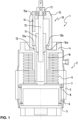
- Figure 1 shows a schematic sectional view of a vacuum variable capacitor according to an embodiment of the present invention.
- Figure 1 shows a schematic sectional view of a vacuum variable capacitor 1 according to an embodiment of the present invention.
- the vacuum variable capacitor 1 comprises a vacuum sealed enclosure 2 with a first plate 3 and a second plate 4 electrically separated by an insulating element 5.
- a fixed electrode 6 advantageously a spiral or cylindrical electrode (or a set of cylindrical surfaces forming an electrode)
- these capacitance generating electrodes can be arranged as intertwined spirals or concentric, equally spaced, cylinders in order to optimize voltage and power capabilities of the capacitor for a given available volume of vacuum dielectric, hence for a given size or footprint of the capacitor.
- a mechanical drive system 10 is provided for translating the movable plate 7 and with it the movable electrode 8 relative to the first plate 3 and the fixed electrode 6 so as to vary the capacitance of the capacitor.
- the mechanical drive 10 comprises a ball screw 11 with a threaded shaft 12 arranged such that by rotating the shaft 12 the distance between the movable plate 7 and the first plate 3 can be adjusted. Thanks to the ball screw, the distance between the movable electrode 7 and the first plate 3 can be modified by applying a small torque to the threaded shaft 12.
- the ball screw 11 is configured such that the capacitance of the capacitor can be adjusted by applying a torque less than or equal to 0.5 N ⁇ m, even more advantageously less than or equal to 0.3 N ⁇ m, especially 0.25 N m.
- a nut 13 is attached to the ball screw 11 and exhibits a first shoulder 13a arranged to abut against the limiting element 14 that is provided to limit the maximum distance between the first plate 3 and the movable plate 7 and with that to define the minimum capacitance of the capacitor 1.
- the limiting element 14 is configured such that the maximum distance between the first plate and the movable plate, and thus the minimum capacitance of the capacitor, is reached when the first shoulder 13a of the nut 13 abuts against the limiting element 14.
- the minimum capacitance is not defined, like in the prior art capacitors, by the maximum compressibility of the vacuum bellows 9 but by the distance between the end of the limiting element facing the movable plate and the first shoulder of the nut.
- the limiting element 14 has the form a threaded pin screwed partially in cap 15 covering the mechanical drive system 10 in particular the ball screw 11.
- the threaded pin 14 can be screwed and unscrewed from outside the cap 15, for instance by means of a screwdriver.
- the maximum distance between the first plate 3 and the movable plate 7, and with this the minimum capacitance of the capacitor 1 can precisely be adjusted.
- the minimum capacitance of the capacitor 1 can also be adjusted by choosing a limiting element of a different length.
- the nut 13 is partially arranged in a guiding element 16 and exhibits a second shoulder 13b arranged to abut against an edge 16a of the guiding element for limiting the minimum distance between the first plate 3 and the movable plate 7 and thus for defining the maximum capacitance of the capacitor.
- a coupling element 17 is provided for attaching the threaded shaft 12 to a drive motor.
Landscapes
- Engineering & Computer Science (AREA)
- Power Engineering (AREA)
- Microelectronics & Electronic Packaging (AREA)
- Fixed Capacitors And Capacitor Manufacturing Machines (AREA)
Description
- The present invention relates to the field of vacuum capacitors, in particular to the field of vacuum variable capacitor.
- Vacuum capacitors are electric capacitors that are suitable for high power applications, typically compatible with voltages of several thousand Volts, or even tens of thousands of Volts thanks to the excellent dielectric properties of vacuum. Vacuum capacitors can carry AC currents (especially RF currents) of tens of Amperes or even hundreds of Amperes thanks to the very low losses of the conducting parts, i.e., metal electrodes and metal collars used for connecting vacuum capacitors to other circuit elements.
- Vacuum variable capacitors constitute a sub-group of vacuum capacitors and are also known for their excellent suitability for high power applications. These vacuum variable capacitors permit the adjustment of the capacitance value by adjusting an electrode position with respect to the other electrode, both situated inside of the vacuum enclosure of the vacuum capacitor. In practice, it is not the electrode separation which is changed but the electrode surface overlap by changing the distance between the plates carrying the electrodes. The range of adjustment of the capacitance value is called tunability and is defined by t = (Cmax-Cmin)/Cmax where Cmax and Cmin are the maximum and the minimum capacitance value which can be achieved with a given capacitor. Most vacuum variable capacitors are designed to provide at least 90% tunability, some will provide tunability of 98% or even more. Typically, a screw and nut system associated with expandable connection joints, also called bellows, allow to bring the actuation from outside the vacuum to the adjustable electrode inside the vacuum enclosure. For example, a stepper motor controlled by a control software may be used for the actuation part to precisely position the movable electrode and therefore to achieve a specific and precise value of the capacitance of the vacuum variable capacitor. The aforementioned elements used to adjust the capacitance value of the vacuum variable capacitor define its mechanical drive system.
- Besides high voltage and current capabilities, a specific quality criterion of the sub-group of vacuum variable capacitors is their drive system's performance. Not only, is it valuable to have a high tunability, but also to provide a long life of the drive system, which can be defined as the number of cycles between Cmax and Cmin until failure, to provide a drive system which is adjustable by relatively modest torque, to provide fast and precise mechanical adjustment to fulfil the high demands of many applications.
- Typical applications of vacuum capacitors include power delivery systems used in the semiconductor manufacturing industry using radio-frequency (for example at 13.56 MHz) powered plasma tools for deposition and etch processes. The primary function of the vacuum variable capacitor is to adjust and match the impedance of the application load to the impedance of the radio-frequency generator in the power delivery circuitry. Because a plasma load has a time-varying impedance (depending on each processing step, ionizing gas state, residual gas pressure, and other factors) it needs to be adapted ("matched") to the impedance of the generator and RF cables which are optimized by industry standards to work for 50 Ohm impedance. Any impedance mismatch can result in the semiconductor manufacturing process being unsuccessful, and in some cases can also result in the destruction of the generator due to reflected electrical power due to the impedance mismatch between generator and load.
- Coming back now to the drive system of vacuum variable capacitors. As stated above, it is desirable to provide a system which can be actuated with modest or low torque. Today most vacuum variable capacitors will require typically stepper motors or other actuators to provide torques larger than 0.4 N·m. in order to be adjusted. It is a goal of the present invention to deliver a vacuum variable capacitor which can be actuated with a reduced torque and without compromising on precision and repeatability of the drive system. To achieve this goal, the vacuum variable capacitor requires a mechanical end stop at the position of the movable electrode corresponding to minimum capacitance Cmin. Prior art vacuum variable capacitors do not normally provide for means to determine a precise value for Cmin. The only available means are basically the bellows being fully compressed. Bellows are not a high precision component, so that this end stop would correspond for example to 32pF in some cases and in other cases to 35pF or 27pF even though the same components (nominally) are being used. Due to this problem, the datasheet of a series-produced vacuum variable capacitor today has to show a higher Cmin value resulting in a smaller capacitance range, and therefore a poorer indicated tunability simply because of this uncertainty. In the example just mentioned, the manufacturer would publish a "safer" Cmin value of, for example, 40pF because the manufacturer knows by experience that whatever the bellows properties within its component tolerances will result in that "safe Cmin" being attainable. In other words, the value published in the datasheet can indeed be reached by the customer for all the delivered capacitors of that type. This reliability is important and the manufacturer agrees to publish a poorer tunability characteristic than would be necessary.
- Vacuum variable capacitors comprising a limiting element for limiting the maximum distance between the movable and the fixed plates of the capacitor are known from
US3040220A ,JP2964248B1 US2002163398A1 andUS2010254066A1 , the proposed limiting elements do not however provide for a satisfactory solution for the problems mentioned above. - The aim of the present invention, therefore, is to provide a vacuum variable capacitor whose capacitance can be adjusted by low torque while allowing for a precise definition of its minimum capacitance value.
- Thus, the object of the present invention is to propose a novel vacuum variable capacitor, with which the above-described drawbacks of the known systems are completely overcome or at least greatly diminished.
- An object of the present invention is in particular to propose a vacuum variable capacitor, whose capacitance can be adjusted with low torque while guaranteeing high precision in the capacitance value.
- According to the present invention, these objectives are achieved in particular through the elements of the independent claim.
- In particular, the objects of the present invention are achieved by a vacuum variable capacitor comprising a vacuum sealed enclosure to contain a vacuum dielectric medium, wherein the enclosure comprises a first plate and a second plate, the said first plate and the said second plate being separated by an electrically insulating element, a fixed electrode attached inside the enclosure to the first plate and a movable electrode attached to a movable plate, wherein the movable plate is attached inside the enclosure to the second plate by means of at least one vacuum bellows, wherein the vacuum capacitor comprises a mechanical drive system for displacing, in particular translating, the movable plate relative to the first plate so as to vary the capacitance of the vacuum capacitor, wherein the mechanical drive system comprises a ball screw arranged to drive the movable plate and wherein the mechanical drive system comprises outside of the vacuum sealed enclosure a limiting element limiting the maximum distance between the first plate and the movable plate, wherein the drive system comprises a nut attached to the ball screw, and wherein the nut comprises a first shoulder configured to abut against the limiting element to limit the maximum distance between the first plate and the movable plate.
- Thanks to the ball screw, the distance between the first plate and the moving plate, and thus the capacitance of the capacitor, can be changed with low torque. This is particularly advantageous in applications where the capacitance must be changed repeatedly and quickly. With low torque, the requirements for the motor normally used to drive the moving plate can be lowered, allowing smaller and cheaper motors to be used. The limiting element makes it possible to define a precise value for the maximum distance between the plates and thus a minimum value for the capacitance. This value can then be used as a reference value for all capacitance values corresponding to other distances between the plates. Since the capacitance varies inversely with the distance between the plates, it is advantageous to use the minimum capacitance as the reference value. An absolute error on the distance between the plates has less influence on the capacitance at the minimum capacitance value than at the maximum value. An accurate reference value at the minimum capacitance is therefore advantageous. In prior art vacuum variable capacitors, the minimum capacitance value is defined by an element inside the vacuum enclosure such as for instance the bellows. This means that this value must be defined before the enclosure is assembled and evacuated and cannot be defined subsequently. The possibility of defining the reference value for the minimum capacitance by a limiting element outside the vacuum enclosure is therefore advantageous. It is in fact possible to measure the capacitance and define this value as a function of this measurement. Furthermore, several prior art vacuum variable capacitors define the minimum capacitance by means of the maximum compressibility of the bellows. This is problematic since this cannot lead to a precise reference value at minimum capacitance.
- As explained above, typical applications of vacuum capacitors include power delivery systems used in the semiconductor manufacturing industry using radio-frequency (for example at 13.56 MHz) powered plasma tools for deposition and etch processes. The primary function of the vacuum variable capacitor is to adjust and match the impedance of the application load to the impedance of the radio-frequency generator in the power delivery circuitry. Because a plasma load has a time-varying impedance (depending on each processing step, ionizing gas state, residual gas pressure, and other factors) it needs to be adapted ("matched") to the impedance of the generator and RF cables which are optimized by industry standards to work for 50 Ohm impedance. Any impedance mismatch can result in the semiconductor manufacturing process being unsuccessful, and in some cases can also result in the destruction of the generator due to reflected electrical power due to the impedance mismatch of the load. It is therefore of primary importance to provide for a vacuum variable capacitor with a precise reference value at minimum capacitance.
- Finally, providing for a drive system that comprises a nut attached to the ball screw, wherein the nut comprises a first shoulder configured to abut against the limiting element to limit the maximum distance between the first plate and the movable plate, represents a simple and cost effective way for defining the reference value at the minimum capacitance value.
- In a first preferred embodiment of the present invention, the maximum distance between the fist plate and the movable plate is adjustable by means of the limiting element. This particularly advantageous since the characteristics of the capacitor can change over time or due to external conditions like temperature. The possibility of being able to adjust the maximum distance and thus the reference value at minimum capacitance thus represents an advantage over the vacuum variable capacitor known in the prior art.
- In a further preferred embodiment of the present invention, the nut is at least partially arranged in a guiding element of the enclosure and the nut comprises a second shoulder configured to abut against an edge of the guiding element to limit the minimum distance between the first plate and the movable plate. With this the maximum capacitance value of the capacitor can be defined.
- In yet another preferred embodiment of the present invention, the vacuum variable capacitor comprises a cap arranged to cover the ball screw. This is advantageous to protect the drive system and in particular the ball screw in order to have a capacitor which performances are guaranteed over a long period of time. The cap can advantageously be configured to cover entirely the ball screw in order to protect the latter against dust and mechanical shocks.
- In a further preferred embodiment of the present invention, the limiting element is at least partially arranged inside the cap. With this the limiting element is also protected by the cap, guaranteeing that the reference value at minimum capacitance value remains constant over time.
- In yet a further preferred embodiment of the present invention, the cap comprises a thread into which the limiting element is at least partially screwed. This represents a particularly simple and cost-effective way of implementing the limiting element.
- In another preferred embodiment of the present invention, the limiting element is a threaded pin. A threaded pin can easily be provided, and the length of the pin can be used to define the minimum capacitance value.
- In yet another preferred embodiment of the present invention, the maximum distance between the first plate and the movable plate is adjustable from outside the cap. With this the minimum capacitance value can be defined and adjusted when the capacitor is fully assembled and even in operation.
- In a further preferred embodiment of the present invention, the maximum distance between the first plate and the movable plate is adjustable by screwing and unscrewing the limiting element into the cap. This represents a particular simple and cost-effective way to provide for a limiting element allowing for adjusting the minimum capacitance value.
- In yet a further preferred embodiment of the present invention, the ball screw is configured such as to be able to increase the distance between the first plate and the movable plate with a torque less than or equal to 0.5 N·m, advantageously less than or equal to 0.3 N·m, especially less than or equal to 0.25 N·m. This allows to lower the requirements of the motor used to drive the movable plate and thus to adjust the capacitance value. With this is smaller and cheaper motor can be used.
- In yet another preferred embodiment of the present invention, the mechanical drive system comprises a coupling element for attaching a threaded shaft of the ball screw to a drive motor. This allows for driving the ball screw with a motor.
-
Figure 1 shows a schematic sectional view of a vacuum variable capacitor according to an embodiment of the present invention. -
Figure 1 shows a schematic sectional view of avacuum variable capacitor 1 according to an embodiment of the present invention. - The
vacuum variable capacitor 1 comprises a vacuum sealedenclosure 2 with afirst plate 3 and a second plate 4 electrically separated by an insulating element 5. Inside the enclosure 2 a fixedelectrode 6, advantageously a spiral or cylindrical electrode (or a set of cylindrical surfaces forming an electrode), is attached to thefirst plate 3. Amovable plate 7 with amovable electrode 8, advantageously a spiral or cylindrical electrode (or as set of cylindrical surfaces forming an electrode), is attached inside theenclosure 2 to the first plate 4 by means of a vacuum bellows 9. As is well known to the skilled person, these capacitance generating electrodes can be arranged as intertwined spirals or concentric, equally spaced, cylinders in order to optimize voltage and power capabilities of the capacitor for a given available volume of vacuum dielectric, hence for a given size or footprint of the capacitor. - A mechanical drive system 10 is provided for translating the
movable plate 7 and with it themovable electrode 8 relative to thefirst plate 3 and the fixedelectrode 6 so as to vary the capacitance of the capacitor. The mechanical drive 10 comprises aball screw 11 with a threadedshaft 12 arranged such that by rotating theshaft 12 the distance between themovable plate 7 and thefirst plate 3 can be adjusted. Thanks to the ball screw, the distance between themovable electrode 7 and thefirst plate 3 can be modified by applying a small torque to the threadedshaft 12. Advantageously, theball screw 11 is configured such that the capacitance of the capacitor can be adjusted by applying a torque less than or equal to 0.5 N·m, even more advantageously less than or equal to 0.3 N·m, especially 0.25 N m. - As can be seen in
Figure 1 , anut 13 is attached to theball screw 11 and exhibits afirst shoulder 13a arranged to abut against the limitingelement 14 that is provided to limit the maximum distance between thefirst plate 3 and themovable plate 7 and with that to define the minimum capacitance of thecapacitor 1. It is important to understand that the limitingelement 14 is configured such that the maximum distance between the first plate and the movable plate, and thus the minimum capacitance of the capacitor, is reached when thefirst shoulder 13a of thenut 13 abuts against the limitingelement 14. With other words, the minimum capacitance is not defined, like in the prior art capacitors, by the maximum compressibility of the vacuum bellows 9 but by the distance between the end of the limiting element facing the movable plate and the first shoulder of the nut. - In the embodiment of
Figure 1 , the limitingelement 14 has the form a threaded pin screwed partially incap 15 covering the mechanical drive system 10 in particular theball screw 11. As it can easily understood fromFigure 1 , the threadedpin 14 can be screwed and unscrewed from outside thecap 15, for instance by means of a screwdriver. By screwing and unscrewing the threadedpin 14, the maximum distance between thefirst plate 3 and themovable plate 7, and with this the minimum capacitance of thecapacitor 1, can precisely be adjusted. Of course, the minimum capacitance of thecapacitor 1 can also be adjusted by choosing a limiting element of a different length. - The
nut 13 is partially arranged in a guidingelement 16 and exhibits asecond shoulder 13b arranged to abut against anedge 16a of the guiding element for limiting the minimum distance between thefirst plate 3 and themovable plate 7 and thus for defining the maximum capacitance of the capacitor. - Advantageously, a
coupling element 17 is provided for attaching the threadedshaft 12 to a drive motor. - Finally, it should be pointed out that the foregoing has outlined one pertinent non-limiting embodiment. It will be clear to those skilled in the art that modifications to the disclosed non-limiting embodiment can be effected. As such, the described non-limiting embodiment ought to be considered merely illustrative of some of the more prominent features and applications. Other beneficial results can be realized by applying the non-limiting embodiments in a different manner or modifying them in ways known to those familiar with the art that fall within the scope of the invention as set forth with the appended claims.
Claims (11)
- Vacuum variable capacitor (1) comprising a vacuum sealed enclosure (2) to contain a vacuum dielectric medium, wherein the enclosure (2) comprises a first plate (3) and a second plate (4), the said first plate (3) and the said second plate (4) being separated by an electrically insulating element (5), a fixed electrode (6) attached inside the enclosure (2) to the first plate (3) and a movable electrode (8) attached to a movable plate (7), wherein the movable plate (7) is attached inside the enclosure (2) to the second plate (4) by means of at least one vacuum bellows (9), wherein the vacuum capacitor (1) comprises a mechanical drive system (10) for displacing, in particular translating, the movable plate (7) relative to the first plate (3) so as to vary the capacitance of the vacuum capacitor (1), wherein the mechanical drive system (10) comprises a ball screw (11) arranged to drive the movable plate (7) and wherein the mechanical drive system (10) comprises outside of the vacuum sealed enclosure (2) a limiting element (14) limiting the maximum distance between the first plate (3) and the movable plate (7),
characterized in that
the drive system comprises a nut (13) attached to the ball screw (11), wherein the nut (13) comprises a first shoulder (13a) configured to abut against the limiting element (14) to limit the maximum distance between the first plate (3) and the movable plate (7). - Vacuum capacitor (1) according to claim 1, wherein the maximum distance between the fist plate (3) and the movable plate (7) is adjustable by means of the limiting element (14).
- Vacuum capacitor (1) according to claim 1 or 2, wherein the nut (13) is at least partially arranged in a guiding element (16) of the enclosure (2) and wherein the nut (13) comprises a second shoulder (13b) configured to abut against an edge (16a) of the guiding element (16) to limit the minimum distance between the first plate (3) and the movable plate (7).
- Vacuum capacitor according to any of the preceding claims, wherein it comprises a cap (15) arranged to cover the ball screw (11).
- Vacuum capacitor according to claim 4, wherein the limiting element (14) is at least partially arranged inside the cap (15).
- Vacuum capacitor according to claim 5, wherein the cap (15) comprises a thread (15a) into which the limiting element (14) is at least partially screwed.
- Vacuum capacitor according to claim 6, wherein the limiting element (14) is a threaded pin.
- Vacuum capacitor according to any one of the claims 4 to 7, wherein the maximum distance between the first plate (3) and the movable plate (7) is adjustable from outside the cap (15).
- Vacuum capacitor according to any one of the claims 6 or 8, wherein the maximum distance between the first plate (3) and the movable plate (7) is adjustable by screwing and unscrewing the limiting element (14) into the cap (15).
- Vacuum capacitor according to any of the preceding claims, wherein the ball screw (11) is configured such as to be able to increase the distance between the first plate (3) and the movable plate (7) with a torque less than or equal to 0.5 N·m, advantageously less than or equal to 0.3 N·m, especially less than or equal to 0.25 N·m.
- Vacuum capacitor according to any of the preceding claims, wherein the mechanical drive system (10) comprises a coupling element (17) for attaching a drive motor to a threaded shaft (12) of the ball screw (11).
Applications Claiming Priority (2)
| Application Number | Priority Date | Filing Date | Title |
|---|---|---|---|
| EP21210518.3A EP4187565A1 (en) | 2021-11-25 | 2021-11-25 | Vacuum variable capacitor |
| PCT/EP2022/077428 WO2023094056A1 (en) | 2021-11-25 | 2022-10-03 | Vacuum variable capacitor |
Publications (2)
| Publication Number | Publication Date |
|---|---|
| EP4214729A1 EP4214729A1 (en) | 2023-07-26 |
| EP4214729B1 true EP4214729B1 (en) | 2024-11-06 |
Family
ID=78789875
Family Applications (2)
| Application Number | Title | Priority Date | Filing Date |
|---|---|---|---|
| EP21210518.3A Withdrawn EP4187565A1 (en) | 2021-11-25 | 2021-11-25 | Vacuum variable capacitor |
| EP22793437.9A Active EP4214729B1 (en) | 2021-11-25 | 2022-10-03 | Vacuum variable capacitor |
Family Applications Before (1)
| Application Number | Title | Priority Date | Filing Date |
|---|---|---|---|
| EP21210518.3A Withdrawn EP4187565A1 (en) | 2021-11-25 | 2021-11-25 | Vacuum variable capacitor |
Country Status (7)
| Country | Link |
|---|---|
| US (1) | US12580133B2 (en) |
| EP (2) | EP4187565A1 (en) |
| JP (1) | JP2024541398A (en) |
| KR (1) | KR20240108405A (en) |
| CN (1) | CN118302832A (en) |
| TW (1) | TW202324462A (en) |
| WO (1) | WO2023094056A1 (en) |
Family Cites Families (10)
| Publication number | Priority date | Publication date | Assignee | Title |
|---|---|---|---|---|
| US3040220A (en) * | 1957-07-16 | 1962-06-19 | Jennings Radio Mfg Corp | Vacuum variable capacitor |
| JP3365082B2 (en) * | 1994-09-29 | 2003-01-08 | 株式会社明電舎 | Vacuum condenser |
| JPH10106888A (en) * | 1996-10-02 | 1998-04-24 | Kyosan Electric Mfg Co Ltd | Vacuum variable capacitor |
| JP2964248B1 (en) * | 1998-08-05 | 1999-10-18 | 株式会社 コムクラフト | Control method of capacitance in vacuum variable capacitor and vacuum variable capacitor using the same |
| JP3960808B2 (en) * | 2001-03-01 | 2007-08-15 | 株式会社ダイヘン | Impedance matcher |
| JP2005174988A (en) * | 2003-12-08 | 2005-06-30 | Meidensha Corp | Vacuum capacitor |
| JP5217382B2 (en) * | 2007-11-20 | 2013-06-19 | 株式会社明電舎 | Vacuum capacitor |
| CN102959657B (en) * | 2010-06-28 | 2016-05-18 | 康姆艾德公司 | Vacuum condenser |
| CN104081484B (en) * | 2012-02-03 | 2017-05-31 | 康姆艾德公司 | variable vacuum capacitor |
| JP6220047B2 (en) * | 2013-03-19 | 2017-10-25 | コメット アクチェンゲゼルシャフト | High voltage capacitor |
-
2021
- 2021-11-25 EP EP21210518.3A patent/EP4187565A1/en not_active Withdrawn
-
2022
- 2022-10-03 US US18/711,161 patent/US12580133B2/en active Active
- 2022-10-03 CN CN202280077819.0A patent/CN118302832A/en active Pending
- 2022-10-03 EP EP22793437.9A patent/EP4214729B1/en active Active
- 2022-10-03 JP JP2024529260A patent/JP2024541398A/en active Pending
- 2022-10-03 WO PCT/EP2022/077428 patent/WO2023094056A1/en not_active Ceased
- 2022-10-03 KR KR1020247016361A patent/KR20240108405A/en active Pending
- 2022-10-13 TW TW111138731A patent/TW202324462A/en unknown
Also Published As
| Publication number | Publication date |
|---|---|
| US20250022662A1 (en) | 2025-01-16 |
| EP4214729A1 (en) | 2023-07-26 |
| KR20240108405A (en) | 2024-07-09 |
| EP4187565A1 (en) | 2023-05-31 |
| CN118302832A (en) | 2024-07-05 |
| TW202324462A (en) | 2023-06-16 |
| US12580133B2 (en) | 2026-03-17 |
| JP2024541398A (en) | 2024-11-08 |
| WO2023094056A1 (en) | 2023-06-01 |
Similar Documents
| Publication | Publication Date | Title |
|---|---|---|
| EP3005385B1 (en) | Vacuum variable capacitor | |
| US11657980B1 (en) | Dielectric fluid variable capacitor | |
| US10110119B2 (en) | Power supply and method of manufacturing | |
| EP2810287B1 (en) | Variable vacuum capacitor | |
| US12580133B2 (en) | Vacuum variable capacitor having a vacuum sealed enclosure and a mechanical drive system | |
| US12051549B2 (en) | Coaxial variable capacitor | |
| US20230360858A1 (en) | Variable capacitor with linear impedance and high voltage breakdown | |
| US12132435B2 (en) | Method for repeatable stepper motor homing | |
| JP4388846B2 (en) | Variable capacitor and impedance matching device including the variable capacitor | |
| EP3005386B1 (en) | Vacuum variable capacitor | |
| HK1229547B (en) | Power suppy and method of manufacturing |
Legal Events
| Date | Code | Title | Description |
|---|---|---|---|
| STAA | Information on the status of an ep patent application or granted ep patent |
Free format text: STATUS: UNKNOWN |
|
| STAA | Information on the status of an ep patent application or granted ep patent |
Free format text: STATUS: THE INTERNATIONAL PUBLICATION HAS BEEN MADE |
|
| PUAI | Public reference made under article 153(3) epc to a published international application that has entered the european phase |
Free format text: ORIGINAL CODE: 0009012 |
|
| STAA | Information on the status of an ep patent application or granted ep patent |
Free format text: STATUS: REQUEST FOR EXAMINATION WAS MADE |
|
| 17P | Request for examination filed |
Effective date: 20230419 |
|
| AK | Designated contracting states |
Kind code of ref document: A1 Designated state(s): AL AT BE BG CH CY CZ DE DK EE ES FI FR GB GR HR HU IE IS IT LI LT LU LV MC ME MK MT NL NO PL PT RO RS SE SI SK SM TR |
|
| P01 | Opt-out of the competence of the unified patent court (upc) registered |
Effective date: 20231115 |
|
| GRAP | Despatch of communication of intention to grant a patent |
Free format text: ORIGINAL CODE: EPIDOSNIGR1 |
|
| STAA | Information on the status of an ep patent application or granted ep patent |
Free format text: STATUS: GRANT OF PATENT IS INTENDED |
|
| RIC1 | Information provided on ipc code assigned before grant |
Ipc: H01G 5/04 20060101ALN20240506BHEP Ipc: H01G 5/013 20060101ALN20240506BHEP Ipc: H01G 2/08 20060101ALN20240506BHEP Ipc: H01G 5/38 20060101ALI20240506BHEP Ipc: H01G 5/017 20060101ALI20240506BHEP Ipc: H01G 5/14 20060101AFI20240506BHEP |
|
| DAV | Request for validation of the european patent (deleted) | ||
| DAX | Request for extension of the european patent (deleted) | ||
| INTG | Intention to grant announced |
Effective date: 20240522 |
|
| GRAS | Grant fee paid |
Free format text: ORIGINAL CODE: EPIDOSNIGR3 |
|
| GRAA | (expected) grant |
Free format text: ORIGINAL CODE: 0009210 |
|
| STAA | Information on the status of an ep patent application or granted ep patent |
Free format text: STATUS: THE PATENT HAS BEEN GRANTED |
|
| AK | Designated contracting states |
Kind code of ref document: B1 Designated state(s): AL AT BE BG CH CY CZ DE DK EE ES FI FR GB GR HR HU IE IS IT LI LT LU LV MC ME MK MT NL NO PL PT RO RS SE SI SK SM TR |
|
| REG | Reference to a national code |
Ref country code: GB Ref legal event code: FG4D |
|
| REG | Reference to a national code |
Ref country code: CH Ref legal event code: EP |
|
| REG | Reference to a national code |
Ref country code: DE Ref legal event code: R096 Ref document number: 602022007566 Country of ref document: DE |
|
| REG | Reference to a national code |
Ref country code: IE Ref legal event code: FG4D |
|
| REG | Reference to a national code |
Ref country code: LT Ref legal event code: MG9D |
|
| REG | Reference to a national code |
Ref country code: NL Ref legal event code: MP Effective date: 20241106 |
|
| PG25 | Lapsed in a contracting state [announced via postgrant information from national office to epo] |
Ref country code: HR Free format text: LAPSE BECAUSE OF FAILURE TO SUBMIT A TRANSLATION OF THE DESCRIPTION OR TO PAY THE FEE WITHIN THE PRESCRIBED TIME-LIMIT Effective date: 20241106 Ref country code: PT Free format text: LAPSE BECAUSE OF FAILURE TO SUBMIT A TRANSLATION OF THE DESCRIPTION OR TO PAY THE FEE WITHIN THE PRESCRIBED TIME-LIMIT Effective date: 20250306 Ref country code: IS Free format text: LAPSE BECAUSE OF FAILURE TO SUBMIT A TRANSLATION OF THE DESCRIPTION OR TO PAY THE FEE WITHIN THE PRESCRIBED TIME-LIMIT Effective date: 20250306 |
|
| PG25 | Lapsed in a contracting state [announced via postgrant information from national office to epo] |
Ref country code: FI Free format text: LAPSE BECAUSE OF FAILURE TO SUBMIT A TRANSLATION OF THE DESCRIPTION OR TO PAY THE FEE WITHIN THE PRESCRIBED TIME-LIMIT Effective date: 20241106 Ref country code: NL Free format text: LAPSE BECAUSE OF FAILURE TO SUBMIT A TRANSLATION OF THE DESCRIPTION OR TO PAY THE FEE WITHIN THE PRESCRIBED TIME-LIMIT Effective date: 20241106 |
|
| REG | Reference to a national code |
Ref country code: AT Ref legal event code: MK05 Ref document number: 1740341 Country of ref document: AT Kind code of ref document: T Effective date: 20241106 |
|
| PG25 | Lapsed in a contracting state [announced via postgrant information from national office to epo] |
Ref country code: BG Free format text: LAPSE BECAUSE OF FAILURE TO SUBMIT A TRANSLATION OF THE DESCRIPTION OR TO PAY THE FEE WITHIN THE PRESCRIBED TIME-LIMIT Effective date: 20241106 |
|
| PG25 | Lapsed in a contracting state [announced via postgrant information from national office to epo] |
Ref country code: ES Free format text: LAPSE BECAUSE OF FAILURE TO SUBMIT A TRANSLATION OF THE DESCRIPTION OR TO PAY THE FEE WITHIN THE PRESCRIBED TIME-LIMIT Effective date: 20241106 |
|
| PG25 | Lapsed in a contracting state [announced via postgrant information from national office to epo] |
Ref country code: NO Free format text: LAPSE BECAUSE OF FAILURE TO SUBMIT A TRANSLATION OF THE DESCRIPTION OR TO PAY THE FEE WITHIN THE PRESCRIBED TIME-LIMIT Effective date: 20250206 |
|
| PG25 | Lapsed in a contracting state [announced via postgrant information from national office to epo] |
Ref country code: LV Free format text: LAPSE BECAUSE OF FAILURE TO SUBMIT A TRANSLATION OF THE DESCRIPTION OR TO PAY THE FEE WITHIN THE PRESCRIBED TIME-LIMIT Effective date: 20241106 Ref country code: GR Free format text: LAPSE BECAUSE OF FAILURE TO SUBMIT A TRANSLATION OF THE DESCRIPTION OR TO PAY THE FEE WITHIN THE PRESCRIBED TIME-LIMIT Effective date: 20250207 Ref country code: AT Free format text: LAPSE BECAUSE OF FAILURE TO SUBMIT A TRANSLATION OF THE DESCRIPTION OR TO PAY THE FEE WITHIN THE PRESCRIBED TIME-LIMIT Effective date: 20241106 |
|
| PG25 | Lapsed in a contracting state [announced via postgrant information from national office to epo] |
Ref country code: PL Free format text: LAPSE BECAUSE OF FAILURE TO SUBMIT A TRANSLATION OF THE DESCRIPTION OR TO PAY THE FEE WITHIN THE PRESCRIBED TIME-LIMIT Effective date: 20241106 |
|
| PG25 | Lapsed in a contracting state [announced via postgrant information from national office to epo] |
Ref country code: RS Free format text: LAPSE BECAUSE OF FAILURE TO SUBMIT A TRANSLATION OF THE DESCRIPTION OR TO PAY THE FEE WITHIN THE PRESCRIBED TIME-LIMIT Effective date: 20250206 |
|
| PG25 | Lapsed in a contracting state [announced via postgrant information from national office to epo] |
Ref country code: SM Free format text: LAPSE BECAUSE OF FAILURE TO SUBMIT A TRANSLATION OF THE DESCRIPTION OR TO PAY THE FEE WITHIN THE PRESCRIBED TIME-LIMIT Effective date: 20241106 |
|
| PG25 | Lapsed in a contracting state [announced via postgrant information from national office to epo] |
Ref country code: DK Free format text: LAPSE BECAUSE OF FAILURE TO SUBMIT A TRANSLATION OF THE DESCRIPTION OR TO PAY THE FEE WITHIN THE PRESCRIBED TIME-LIMIT Effective date: 20241106 |
|
| PG25 | Lapsed in a contracting state [announced via postgrant information from national office to epo] |
Ref country code: EE Free format text: LAPSE BECAUSE OF FAILURE TO SUBMIT A TRANSLATION OF THE DESCRIPTION OR TO PAY THE FEE WITHIN THE PRESCRIBED TIME-LIMIT Effective date: 20241106 |
|
| PG25 | Lapsed in a contracting state [announced via postgrant information from national office to epo] |
Ref country code: RO Free format text: LAPSE BECAUSE OF FAILURE TO SUBMIT A TRANSLATION OF THE DESCRIPTION OR TO PAY THE FEE WITHIN THE PRESCRIBED TIME-LIMIT Effective date: 20241106 |
|
| PG25 | Lapsed in a contracting state [announced via postgrant information from national office to epo] |
Ref country code: SK Free format text: LAPSE BECAUSE OF FAILURE TO SUBMIT A TRANSLATION OF THE DESCRIPTION OR TO PAY THE FEE WITHIN THE PRESCRIBED TIME-LIMIT Effective date: 20241106 |
|
| PG25 | Lapsed in a contracting state [announced via postgrant information from national office to epo] |
Ref country code: CZ Free format text: LAPSE BECAUSE OF FAILURE TO SUBMIT A TRANSLATION OF THE DESCRIPTION OR TO PAY THE FEE WITHIN THE PRESCRIBED TIME-LIMIT Effective date: 20241106 |
|
| PG25 | Lapsed in a contracting state [announced via postgrant information from national office to epo] |
Ref country code: IT Free format text: LAPSE BECAUSE OF FAILURE TO SUBMIT A TRANSLATION OF THE DESCRIPTION OR TO PAY THE FEE WITHIN THE PRESCRIBED TIME-LIMIT Effective date: 20241106 |
|
| REG | Reference to a national code |
Ref country code: DE Ref legal event code: R097 Ref document number: 602022007566 Country of ref document: DE |
|
| PG25 | Lapsed in a contracting state [announced via postgrant information from national office to epo] |
Ref country code: SE Free format text: LAPSE BECAUSE OF FAILURE TO SUBMIT A TRANSLATION OF THE DESCRIPTION OR TO PAY THE FEE WITHIN THE PRESCRIBED TIME-LIMIT Effective date: 20241106 |
|
| PLBE | No opposition filed within time limit |
Free format text: ORIGINAL CODE: 0009261 |
|
| STAA | Information on the status of an ep patent application or granted ep patent |
Free format text: STATUS: NO OPPOSITION FILED WITHIN TIME LIMIT |
|
| 26N | No opposition filed |
Effective date: 20250807 |
|
| REG | Reference to a national code |
Ref country code: CH Ref legal event code: U11 Free format text: ST27 STATUS EVENT CODE: U-0-0-U10-U11 (AS PROVIDED BY THE NATIONAL OFFICE) Effective date: 20251101 |
|
| PGFP | Annual fee paid to national office [announced via postgrant information from national office to epo] |
Ref country code: DE Payment date: 20251021 Year of fee payment: 4 |
|
| PGFP | Annual fee paid to national office [announced via postgrant information from national office to epo] |
Ref country code: FR Payment date: 20251030 Year of fee payment: 4 |
|
| PGFP | Annual fee paid to national office [announced via postgrant information from national office to epo] |
Ref country code: CH Payment date: 20251101 Year of fee payment: 4 |