EP4214412B1 - Joint for segmented wind turbine blade, segmented wind turbine blade and method for manufacturing the same - Google Patents
Joint for segmented wind turbine blade, segmented wind turbine blade and method for manufacturing the same Download PDFInfo
- Publication number
- EP4214412B1 EP4214412B1 EP20962718.1A EP20962718A EP4214412B1 EP 4214412 B1 EP4214412 B1 EP 4214412B1 EP 20962718 A EP20962718 A EP 20962718A EP 4214412 B1 EP4214412 B1 EP 4214412B1
- Authority
- EP
- European Patent Office
- Prior art keywords
- laminate
- scarfed
- blade
- protruding
- laminates
- Prior art date
- Legal status (The legal status is an assumption and is not a legal conclusion. Google has not performed a legal analysis and makes no representation as to the accuracy of the status listed.)
- Active
Links
Images

Classifications
-
- B—PERFORMING OPERATIONS; TRANSPORTING
- B29—WORKING OF PLASTICS; WORKING OF SUBSTANCES IN A PLASTIC STATE IN GENERAL
- B29C—SHAPING OR JOINING OF PLASTICS; SHAPING OF MATERIAL IN A PLASTIC STATE, NOT OTHERWISE PROVIDED FOR; AFTER-TREATMENT OF THE SHAPED PRODUCTS, e.g. REPAIRING
- B29C70/00—Shaping composites, i.e. plastics material comprising reinforcements, fillers or preformed parts, e.g. inserts
- B29C70/04—Shaping composites, i.e. plastics material comprising reinforcements, fillers or preformed parts, e.g. inserts comprising reinforcements only, e.g. self-reinforcing plastics
- B29C70/28—Shaping operations therefor
- B29C70/30—Shaping by lay-up, i.e. applying fibres, tape or broadsheet on a mould, former or core; Shaping by spray-up, i.e. spraying of fibres on a mould, former or core
- B29C70/34—Shaping by lay-up, i.e. applying fibres, tape or broadsheet on a mould, former or core; Shaping by spray-up, i.e. spraying of fibres on a mould, former or core and shaping or impregnating by compression, i.e. combined with compressing after the lay-up operation
- B29C70/342—Shaping by lay-up, i.e. applying fibres, tape or broadsheet on a mould, former or core; Shaping by spray-up, i.e. spraying of fibres on a mould, former or core and shaping or impregnating by compression, i.e. combined with compressing after the lay-up operation using isostatic pressure
-
- B—PERFORMING OPERATIONS; TRANSPORTING
- B29—WORKING OF PLASTICS; WORKING OF SUBSTANCES IN A PLASTIC STATE IN GENERAL
- B29C—SHAPING OR JOINING OF PLASTICS; SHAPING OF MATERIAL IN A PLASTIC STATE, NOT OTHERWISE PROVIDED FOR; AFTER-TREATMENT OF THE SHAPED PRODUCTS, e.g. REPAIRING
- B29C70/00—Shaping composites, i.e. plastics material comprising reinforcements, fillers or preformed parts, e.g. inserts
- B29C70/68—Shaping composites, i.e. plastics material comprising reinforcements, fillers or preformed parts, e.g. inserts by incorporating or moulding on preformed parts, e.g. inserts or layers, e.g. foam blocks
- B29C70/86—Incorporated in coherent impregnated reinforcing layers, e.g. by winding
-
- B—PERFORMING OPERATIONS; TRANSPORTING
- B29—WORKING OF PLASTICS; WORKING OF SUBSTANCES IN A PLASTIC STATE IN GENERAL
- B29D—PRODUCING PARTICULAR ARTICLES FROM PLASTICS OR FROM SUBSTANCES IN A PLASTIC STATE
- B29D99/00—Subject matter not provided for in other groups of this subclass
- B29D99/0025—Producing blades or the like, e.g. blades for turbines, propellers, or wings
- B29D99/0028—Producing blades or the like, e.g. blades for turbines, propellers, or wings hollow blades
-
- F—MECHANICAL ENGINEERING; LIGHTING; HEATING; WEAPONS; BLASTING
- F03—MACHINES OR ENGINES FOR LIQUIDS; WIND, SPRING, OR WEIGHT MOTORS; PRODUCING MECHANICAL POWER OR A REACTIVE PROPULSIVE THRUST, NOT OTHERWISE PROVIDED FOR
- F03D—WIND MOTORS
- F03D1/00—Wind motors with rotation axis substantially parallel to the air flow entering the rotor
- F03D1/06—Rotors
- F03D1/065—Rotors characterised by their construction elements
- F03D1/0675—Rotors characterised by their construction elements of the blades
- F03D1/0677—Longitudinally segmented blades; Connectors therefor
-
- F—MECHANICAL ENGINEERING; LIGHTING; HEATING; WEAPONS; BLASTING
- F05—INDEXING SCHEMES RELATING TO ENGINES OR PUMPS IN VARIOUS SUBCLASSES OF CLASSES F01-F04
- F05B—INDEXING SCHEME RELATING TO WIND, SPRING, WEIGHT, INERTIA OR LIKE MOTORS, TO MACHINES OR ENGINES FOR LIQUIDS COVERED BY SUBCLASSES F03B, F03D AND F03G
- F05B2230/00—Manufacture
- F05B2230/60—Assembly methods
-
- F—MECHANICAL ENGINEERING; LIGHTING; HEATING; WEAPONS; BLASTING
- F05—INDEXING SCHEMES RELATING TO ENGINES OR PUMPS IN VARIOUS SUBCLASSES OF CLASSES F01-F04
- F05B—INDEXING SCHEME RELATING TO WIND, SPRING, WEIGHT, INERTIA OR LIKE MOTORS, TO MACHINES OR ENGINES FOR LIQUIDS COVERED BY SUBCLASSES F03B, F03D AND F03G
- F05B2240/00—Components
- F05B2240/20—Rotors
- F05B2240/30—Characteristics of rotor blades, i.e. of any element transforming dynamic fluid energy to or from rotational energy and being attached to a rotor
- F05B2240/302—Segmented or sectional blades
-
- Y—GENERAL TAGGING OF NEW TECHNOLOGICAL DEVELOPMENTS; GENERAL TAGGING OF CROSS-SECTIONAL TECHNOLOGIES SPANNING OVER SEVERAL SECTIONS OF THE IPC; TECHNICAL SUBJECTS COVERED BY FORMER USPC CROSS-REFERENCE ART COLLECTIONS [XRACs] AND DIGESTS
- Y02—TECHNOLOGIES OR APPLICATIONS FOR MITIGATION OR ADAPTATION AGAINST CLIMATE CHANGE
- Y02E—REDUCTION OF GREENHOUSE GAS [GHG] EMISSIONS, RELATED TO ENERGY GENERATION, TRANSMISSION OR DISTRIBUTION
- Y02E10/00—Energy generation through renewable energy sources
- Y02E10/70—Wind energy
- Y02E10/72—Wind turbines with rotation axis in wind direction
-
- Y—GENERAL TAGGING OF NEW TECHNOLOGICAL DEVELOPMENTS; GENERAL TAGGING OF CROSS-SECTIONAL TECHNOLOGIES SPANNING OVER SEVERAL SECTIONS OF THE IPC; TECHNICAL SUBJECTS COVERED BY FORMER USPC CROSS-REFERENCE ART COLLECTIONS [XRACs] AND DIGESTS
- Y02—TECHNOLOGIES OR APPLICATIONS FOR MITIGATION OR ADAPTATION AGAINST CLIMATE CHANGE
- Y02P—CLIMATE CHANGE MITIGATION TECHNOLOGIES IN THE PRODUCTION OR PROCESSING OF GOODS
- Y02P70/00—Climate change mitigation technologies in the production process for final industrial or consumer products
- Y02P70/50—Manufacturing or production processes characterised by the final manufactured product
Definitions
- the present disclosure relates generally to wind turbines and more particularly to a joint for a segmented wind turbine blade, a segmented wind turbine blade and a method for manufacturing the same.
- a segmented blade can be joined or assembled in various different ways, such as by means of bolted joint connections, adhesive joints, joining by lamination etc. These methods of joining are well known and proven from many applications in e.g. automotive, aerospace, and even within wind turbine blade design. However, implementation of these joining strategies are not well proven, and are not widespread in the application of segmented blades. This is strongly influenced from the fact that, although segmented blade concepts have existed in theory for decades, actual implementation and industrialization is limited within the wind industry. The increased technical complexity and derived cost increase of the blade has historically not favoured segmented blade design. But as the development of ever increasing rotor size for wind turbines in complex terrain is accelerating, this picture is starting to change. The need for segmented blades is emerging rapidly, having positive impact on the economy of certain wind projects. Hence, development and application of mechanical joints for segmented blades are an emerging technology, where mechanical joint technologies will be applied in new and innovative solutions.
- Some embodiments of the present invention provide a joint for a segmented wind turbine blade, a segmented wind turbine blade and a method for manufacturing a segmented wind turbine blade.
- a joint for a segmented wind turbine blade comprises a laminate glove integrally formed on a first blade segment of the segmented wind turbine blade, and a protruding laminate integrally formed on a second blade segment of the segmented wind turbine blade.
- the laminate glove is configured for housing the protruding laminate, and when the segmented wind turbine blade is assembled on-site, the laminate glove and the protruding laminate are connected together so that the first blade segment is assembled with the second blade segment.
- the laminate glove has an outer glove laminate and an inner glove laminate, and the protruding laminate is located between the outer glove laminate and the inner glove laminate.
- the protruding laminate is tapered in a spanwise direction of the segmented wind turbine blade, and the outer glove laminate and the inner glove laminate form a tapered glove opening for housing the tapered protruding laminate.
- the joint comprises the laminate gloves respectively formed on a suction side and a pressure side of the first blade segment, and the protruding laminates respectively formed on a suction side and a pressure side of the second blade segment, and wherein the laminate glove on the suction side is configured for housing the protruding laminate on the suction side, and the laminate glove on the pressure side is configured for housing the protruding laminate on the pressure side.
- the laminate glove and the protruding laminate are connected by adhesive or resin; or the laminate glove and the protruding laminate are connected by mechanical fasteners.
- a segmented wind turbine blade comprises at least two blade segments and one or more joints.
- the at least two blade segments comprises a first blade segment and a second blade segment.
- the one or more joints are configured for connecting the first blade segment and the second blade segment.
- Each of the one or more joints comprises a laminate glove integrally formed on the first blade segment, and a protruding laminate integrally formed on the second blade segment.
- the protruding laminate is housed in and connected with the laminate glove so that the first blade segment and the second blade segment are assembled together.
- the joint is positioned at any given desired spanwise location of the segmented wind turbine blade; or the joint is positioned at any given desired chordwise location of the segmented wind turbine blade; or the joint is positioned in any given desired orientation in a cross section of the segmented wind turbine blade.
- a method for manufacturing a segmented wind turbine blade at least comprising a first blade segment and a second blade segment.
- the method comprises steps of: laying up one or more material layers in a blade mold, the one or more material layers comprising a laminate glove of the first blade segment and a protruding laminate of the second blade segment, the laminate glove housing the protruding laminate; co-infusing the one or more material layers together in the blade mold so as to form a single-piece wind turbine blade; demolding the single-piece wind turbine blade from the blade mold; and separating the laminate glove from the protruding laminate to form the first blade segment with the laminate glove and the second blade segment with the protruding laminate so that the segmented wind turbine blade is formed, and the first blade segment and the second blade segment are able to be reassembled together by connection of the laminate glove and the protruding laminate when the segmented wind turbine blade is assembled on-site.
- the laminate glove has an outer glove laminate and an inner glove laminate, and the protruding laminate is located between the outer glove laminate and the inner glove laminate.
- the laying up the one or more material layers comprises: wrapping the inner glove laminate onto the protruding laminate prior to co-infusion.
- the method further comprising adding between the laminate glove and the protruding laminate, a processing material for facilitating disassembly of the laminate glove and the protruding laminate during laying up the one or more material layers; or adding between the laminate glove and the protruding laminate, a processing material for facilitating disassembly of the laminate glove and the protruding laminate during laying up the one or more material layers, and covering the protruding laminate with the processing material.
- the method further comprising removing the processing material from the protruding laminate before re-assembly.
- the blade mold comprises two mold halves, and the laying up the one or more material layers in the blade mold and the co-infusing the one or more material layers together in the blade mold comprises: laying up and co-infusing the one or more material layers respectively in the two mold halves so as to form a suction side blade shell and a pressure side blade shell respectively, wherein the laminate glove and the protruding laminate are placed in each of the two mold halves.
- the method further comprising: closing the two mold halves; and assembling the suction side blade shell and the pressure side blade shell together to form the single-piece wind turbine blade.
- the co-infusing the one or more material layers together in the blade mold comprises: co-infusing the one or more material layers together with a liquid resin in the blade mold so as to cure the one or more material layers.
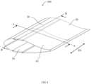
- FIG. 1 illustrates a schematic view of a segmented wind turbine blade 100 according to one embodiment of the present disclosure.
- the segmented wind turbine blade 100 may include at least two blade segments and one or more joints 30 for connecting the at least two blade segments.
- the at least two blade segments may include for example, but be not limited to a first blade segment 10 and a second blade segment 20.
- the one or more joints 30 is used for the segmented wind turbine blade 100 and is configured for connecting the first blade segment 10 and the second blade segment 20.
- the first blade segment 10 and the second blade segment 20 of the segmented wind turbine blade 100 can be assembled together, thereby enabling transportation of the wind turbine blade 100 in segments, and for the segments to be assembled on-site.
- the first blade segment 10 of the segmented wind turbine blade 100 includes one of a blade root segment and a blade tip segment
- the second blade segment 20 of the segmented wind turbine blade 100 includes the other of the blade root segment and the blade tip segment.
- the first blade segment 10 may include a blade root segment
- the second blade segment 20 may include a blade tip segment
- the first blade segment 10 may include the blade tip segment
- the second blade segment 20 may include the blade root segment.
- segmented wind turbine blade 100 of the present disclosure should be not limited to include only two blade segments. In other embodiments, the segmented wind turbine blade 100 of the present disclosure may also include three, four or even more blade segments. The number of the segmented wind turbine blade 100 of the present disclosure may vary from two to any desired number. Furthermore, the segmented wind turbine blade 100 of the present disclosure should be not limited to include the blade root segment and the blade tip segment. In other embodiments, the segmented wind turbine blade 100 of the present disclosure may also include one or more medium blade segments located between the blade root segment and the blade tip segment.
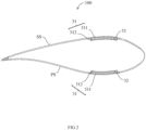
- FIG. 2 illustrates a cross-sectional view of the segmented wind turbine blade 100 of FIG. 1 taken along line A-A.
- FIG. 3 illustrates a cross-sectional view of the segmented wind turbine blade 100 of FIG. 1 taken along line B-B.
- each joint 30 may include a laminate glove 31 and a protruding laminate 32.
- the laminate glove 31 is configured for housing the protruding laminate 32.
- the laminate glove 31 has the size and the shape so to fit the protruding laminate 32.
- the laminate glove 31 and the protruding laminate 32 of the joint 30 are co-infused during manufacturing of the segmented wind turbine blade 100.
- FIG. 4 illustrates a schematic view of a portion of a first blade segment 10 of one embodiment according to the present disclosure.
- the laminate glove 31 of the joint 30 is integrally formed on the first blade segment 10 of the segmented wind turbine blade 100.
- the laminate glove 31 is as an integral part of the first blade segment 10.
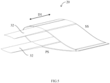
- FIG. 5 illustrates a schematic view of a second blade segment 20 according to one embodiment of the present disclosure.
- the protruding laminate 32 of the joint 30 is integrally formed on the second blade segment 20 of the segmented wind turbine blade 100.
- the protruding laminate 32 is as an integral part of the second blade segment 20.
- the laminate glove 31 may house the protruding laminate 32 and the laminate glove 31 and the protruding laminate 32 may be connected together by various connecting methods so that the first blade segment 10 is assembled with the second blade segment 20.
- the joint 30 of the present disclosure may realize disassembly for transportation of the wind turbine blade 100 and re-assembly on-site for installation.
- the laminate glove 31 of the joint 30 may have an outer glove laminate 311 and an inner glove laminate 312.
- the protruding laminate 32 of the joint 30 may be located between the outer glove laminate 311 and the inner glove laminate 312 of the laminate glove 31. Therefore, the protruding laminate 32 may be housed in the laminate glove 31.
- the laminate glove 31 and the protruding laminate 32 may be connected together by adhesive or resin.
- the adhesive or the resin may act as a load transferring mechanism between the laminate glove 31 and the protruding laminate 32.
- the laminate glove 31 and the protruding laminate 32 may define one or more holes (not shown) for mechanical fasteners, and the laminate glove 31 and the protruding laminate 32 may be connected together by the mechanical fasteners.
- the protruding laminate 32 is tapered in a spanwise direction D1 of the segmented wind turbine blade 100, and correspondingly, the outer glove laminate 311 and the inner glove laminate 312 of the laminate glove 31 form a tapered glove opening 313 for housing the tapered protruding laminate 32.
- Such a tapered mating structure of the laminate glove 31 and the protruding laminate 32 can facilitate disassembly of the laminate glove 31 and the protruding laminate 32.
- the segmented wind turbine blade 100 may include the one or more joints 30 on a suction side (SS) and the one or more joints 30 on a pressure side (PS).
- SS suction side
- PS pressure side
- one joint 30 on the suction side and one joint 30 on the pressure side are shown as an example.
- Each joint 30 on the suction side includes the laminate glove 31 formed on a suction side of the first blade segment 10 and the protruding laminate 32 formed on a suction side of the second blade segment 20.
- the laminate glove 31 on the suction side is configured for housing the protruding laminate 32 on the suction side so as to create a load transferring joint connecting the first blade segment 10 and the second blade segment 20 on the suction side.
- Each joint 30 on the pressure side includes the laminate glove 31 formed on the pressure side of the first blade segment 10 and the protruding laminate 32 formed on the pressure side of the second blade segment 20.
- the laminate glove 31 on the pressure side is configured for housing the protruding laminate 32 on the pressure side so as to create a load transferring joint connecting the first blade segment 10 and the second blade segment 20 on the pressure side.
- the joint 30, i.e. the laminate glove 31 and the corresponding protruding laminate 32 may be positioned at any given desired spanwise location of the segmented wind turbine blade 100, and the joint 30 may be positioned at any given desired chordwise location of the segmented wind turbine blade 100.
- the joint 30 may also be positioned in any given desired orientation in a cross section of the segmented wind turbine blade 100.
- the segmented wind turbine blade 100 may include a plurality of joints 30 in a cross-section.
- the plurality of joints 30 may be positioned in any desired pattern or spacing sequence in a given cross section. That is to say, the first blade segment 10 may include one or more laminate gloves 31, and the second blade segment 20 may include one or more corresponding protruding laminates 32.
- the segmented wind turbine blade 100 of the present disclosure adopts the joint 30 with the laminate glove 31 fitting the protruding laminate 32 and may be thus disassembled for transportation and re-assembled on-site for installation.
- the segmented wind turbine blade 100 of the present disclosure is completely scalable in the number of connections per joint 30.
- the segmented wind turbine blade 100 of the present disclosure is completely scalable in dimensions, positioning, and orientation.
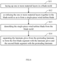
- FIG. 6 illustrates a flow chart of a method for manufacturing the segmented wind turbine blade 100 according to one embodiment of the present disclosure.
- the segmented wind turbine blade 100 at least includes the first blade segment 10 and the second blade segment 20.
- a method for manufacturing the segmented wind turbine blade 100 according to one embodiment of the present disclosure may include steps S11 to S14.
- step S11 one or more material layers are laid up in a blade mold.
- the one or more material layers include the laminate glove 31 of the first blade segment 10 and the protruding laminate 32 of the second blade segment 20.
- the laminate glove 31 of the first blade segment 10 houses the protruding laminate 32 of the second blade segment 20.
- the one or more material layers may include one or more fiber layers.
- the one or more fiber layers may include at least one of glass fiber layers and carbon fiber layers.
- the one or more material layers may further include one or more core material layers made of polymer foam or balsa wood.
- step S12 the one or more material layers are co-infused together in the blade mold so as to form a single-piece wind turbine blade 100.
- the one or more material layers are co-infused together with a liquid resin in the blade mold so as to cure the one or more material layers.
- step S13 the single-piece wind turbine blade 100 is demolded from the blade mold.
- step S14 the laminate glove 31 is separated from the protruding laminate 32 to form the first blade segment 10 with the laminate glove 31 and the second blade segment 20 with the protruding laminate 32 so that the segmented wind turbine blade 100 is formed, and the first blade segment 10 and the second blade segment 20 are able to be reassembled together by connection of the laminate glove 31 and the protruding laminate 32 when the segmented wind turbine blade 100 is assembled on-site.
- the method of the present disclosure may manufacture the segmented wind turbine blade 100 in a non-segmented blade mold with the co-infused laminate glove 31 fitting the protruding laminate 32, which can be subsequently disassembled for transportation and re-assembled on-site for installation.
- the method of the present disclosure enables a unique elimination of tolerance chains, elsewhere causing difficulties of aligning segments for assembly on-site.
- the method of the present disclosure does not incur additional capital expenditures on manufacturing as the non-segmented blade mold is utilized.
- the laminate glove 31 has an outer glove laminate 311 and an inner glove laminate 312 as shown in FIGS. 3 and 4 , and the protruding laminate 32 is located between the outer glove laminate 311 and the inner glove laminate 312.
- the laying up the one or more material layers of step S11 may include: wrapping the inner glove laminate 312 onto the protruding laminate 32 prior to co-infusion.
- the laminate glove 31 and the protruding laminate 32 are co-infused in the blade mold.
- the laminate glove 31 and the protruding laminate 32 are processed in such a specific way, which enables disassembly of the two elements subsequent to demolding, and for re-assembly after transportation to the wind farm site.
- the method of the present disclosure may further include: adding between the laminate glove 31 and the protruding laminate 32, a processing material for facilitating disassembly of the laminate glove 31 and the protruding laminate 32 during laying up the one or more material layers of step S11.
- the adding the processing material between the laminate glove 31 and the protruding laminate 32 may include: covering the protruding laminate 32 with the processing material.
- the processing material of the present disclosure may have the characteristics of surface tension and bonding characteristics, which enables disassembly of the protruding laminate 32 and the laminate glove 31. Hence making possible for having such the segmented wind turbine blade 100, which can be re-assembled.
- the processing material may include Teflon.
- the method of the present disclosure may further include: removing the processing material from the protruding laminate 32 before re-assembly.
- the blade mold for manufacturing the segmented wind turbine blade 100 according to the present disclosure may include two mold halves.
- the one or more material layers may be laid up and co-infused respectively in the two mold halves so as to form a suction side blade shell and a pressure side blade shell respectively.
- the laminate glove 31 and the protruding laminate 32 are placed in each of the two mold halves. Therefore, the laminate glove 31 and the corresponding protruding laminate 32 on the suction side, as well as the laminate glove 31 and the corresponding protruding laminate 32 on the pressure side are formed.
- the method of the present disclosure may further include: closing the two mold halves; and assembling the suction side blade shell and the pressure side blade shell together to form the single-piece wind turbine blade 100.
- the method of the present disclosure can manufacture the segmented wind turbine blade 100 in a blade mold in a single piece, and can be demolded in a single piece. Thus, the method of the present disclosure has a lower manufacturing cost.
Landscapes
- Engineering & Computer Science (AREA)
- Mechanical Engineering (AREA)
- Chemical & Material Sciences (AREA)
- Composite Materials (AREA)
- Life Sciences & Earth Sciences (AREA)
- Sustainable Development (AREA)
- Sustainable Energy (AREA)
- Combustion & Propulsion (AREA)
- General Engineering & Computer Science (AREA)
- Wind Motors (AREA)
Description
- The present disclosure relates generally to wind turbines and more particularly to a joint for a segmented wind turbine blade, a segmented wind turbine blade and a method for manufacturing the same.
- Modern wind turbines continue to grow in size and be equipped with increasingly long wind turbine blades in order to increase the power production. As the blades get longer, transportation of such blades can be challenging or even impossible in some regions of the world. Navigating in complex terrain and in regions with poor infrastructure poses a challenge for transporting the long blades by road, and in some cases, there is a limit to the length of a blade that can be transported to the wind turbine site. A way of solving this challenge is by blade segmentation, whereby the blade is transported in two or more segments, and is later assembled on-site. A segmented blade offers several additional benefits. The investment into manufacturing assets for producing very long blades can be reduced and transportation cost can be reduced. Hence segmented blades have the potential of bringing sustainable clean wind energy to regions that would otherwise not be a possibility, and improve the business case and economic performance of wind farms located in areas where transportation is challenging.
- A segmented blade can be joined or assembled in various different ways, such as by means of bolted joint connections, adhesive joints, joining by lamination etc. These methods of joining are well known and proven from many applications in e.g. automotive, aerospace, and even within wind turbine blade design. However, implementation of these joining strategies are not well proven, and are not widespread in the application of segmented blades. This is strongly influenced from the fact that, although segmented blade concepts have existed in theory for decades, actual implementation and industrialization is limited within the wind industry. The increased technical complexity and derived cost increase of the blade has historically not favoured segmented blade design. But as the development of ever increasing rotor size for wind turbines in complex terrain is accelerating, this picture is starting to change. The need for segmented blades is emerging rapidly, having positive impact on the economy of certain wind projects. Hence, development and application of mechanical joints for segmented blades are an emerging technology, where mechanical joint technologies will be applied in new and innovative solutions.
- An example of a prior art system can be found in
DE 10 2010 015392 B4 . - Some embodiments of the present invention provide a joint for a segmented wind turbine blade, a segmented wind turbine blade and a method for manufacturing a segmented wind turbine blade.
- In one aspect, a joint for a segmented wind turbine blade is provided. The joint comprises a laminate glove integrally formed on a first blade segment of the segmented wind turbine blade, and a protruding laminate integrally formed on a second blade segment of the segmented wind turbine blade. The laminate glove is configured for housing the protruding laminate, and when the segmented wind turbine blade is assembled on-site, the laminate glove and the protruding laminate are connected together so that the first blade segment is assembled with the second blade segment.
In a particular embodiment, the laminate glove has an outer glove laminate and an inner glove laminate, and the protruding laminate is located between the outer glove laminate and the inner glove laminate.
In a particular embodiment, the protruding laminate is tapered in a spanwise direction of the segmented wind turbine blade, and the outer glove laminate and the inner glove laminate form a tapered glove opening for housing the tapered protruding laminate.
In a particular embodiment, the joint comprises the laminate gloves respectively formed on a suction side and a pressure side of the first blade segment, and the protruding laminates respectively formed on a suction side and a pressure side of the second blade segment, and wherein the laminate glove on the suction side is configured for housing the protruding laminate on the suction side, and the laminate glove on the pressure side is configured for housing the protruding laminate on the pressure side.
In a particular embodiment, the laminate glove and the protruding laminate are connected by adhesive or resin; or the laminate glove and the protruding laminate are connected by mechanical fasteners. - In another aspect, a segmented wind turbine blade is provided. The segmented wind turbine blade comprises at least two blade segments and one or more joints. The at least two blade segments comprises a first blade segment and a second blade segment. The one or more joints are configured for connecting the first blade segment and the second blade segment. Each of the one or more joints comprises a laminate glove integrally formed on the first blade segment, and a protruding laminate integrally formed on the second blade segment. The protruding laminate is housed in and connected with the laminate glove so that the first blade segment and the second blade segment are assembled together.
In a particular embodiment, the joint is positioned at any given desired spanwise location of the segmented wind turbine blade; or the joint is positioned at any given desired chordwise location of the segmented wind turbine blade; or the joint is positioned in any given desired orientation in a cross section of the segmented wind turbine blade. - In still another aspect, a method for manufacturing a segmented wind turbine blade is provided. The segmented wind turbine blade at least comprising a first blade segment and a second blade segment. The method comprises steps of: laying up one or more material layers in a blade mold, the one or more material layers comprising a laminate glove of the first blade segment and a protruding laminate of the second blade segment, the laminate glove housing the protruding laminate; co-infusing the one or more material layers together in the blade mold so as to form a single-piece wind turbine blade; demolding the single-piece wind turbine blade from the blade mold; and separating the laminate glove from the protruding laminate to form the first blade segment with the laminate glove and the second blade segment with the protruding laminate so that the segmented wind turbine blade is formed, and the first blade segment and the second blade segment are able to be reassembled together by connection of the laminate glove and the protruding laminate when the segmented wind turbine blade is assembled on-site.
In a particular embodiment, the laminate glove has an outer glove laminate and an inner glove laminate, and the protruding laminate is located between the outer glove laminate and the inner glove laminate.
In a particular embodiment, the laying up the one or more material layers comprises: wrapping the inner glove laminate onto the protruding laminate prior to co-infusion.
In a particular embodiment, the method further comprising adding between the laminate glove and the protruding laminate, a processing material for facilitating disassembly of the laminate glove and the protruding laminate during laying up the one or more material layers; or adding between the laminate glove and the protruding laminate, a processing material for facilitating disassembly of the laminate glove and the protruding laminate during laying up the one or more material layers, and covering the protruding laminate with the processing material.
In a particular embodiment, the method further comprising removing the processing material from the protruding laminate before re-assembly.
In a particular embodiment, the blade mold comprises two mold halves, and the laying up the one or more material layers in the blade mold and the co-infusing the one or more material layers together in the blade mold comprises: laying up and co-infusing the one or more material layers respectively in the two mold halves so as to form a suction side blade shell and a pressure side blade shell respectively, wherein the laminate glove and the protruding laminate are placed in each of the two mold halves.
In a particular embodiment, the method further comprising: closing the two mold halves; and assembling the suction side blade shell and the pressure side blade shell together to form the single-piece wind turbine blade.
In a particular embodiment, the co-infusing the one or more material layers together in the blade mold comprises: co-infusing the one or more material layers together with a liquid resin in the blade mold so as to cure the one or more material layers. - To describe the technical solutions in embodiments of the present disclosure more clearly, drawings in descriptions of the embodiments of the present disclosure will be briefly introduced below. It is apparent that the drawings described below are merely some embodiments of the present disclosure and other drawings may be obtained by those of ordinary skill in the art based on these drawings without resorting to creative labor.
-
FIG. 1 illustrates a schematic view of a segmented wind turbine blade according to one embodiment of the present disclosure. -
FIG. 2 illustrates a cross-sectional view of the segmented wind turbine blade ofFIG. 1 taken along line A-A. -
FIG. 3 illustrates a cross-sectional view of the segmented wind turbine blade ofFIG. 1 taken along line B-B. -
FIG. 4 illustrates a schematic view of a portion of a first blade segment of one embodiment according to the present disclosure. -
FIG. 5 illustrates a schematic view of a second blade segment according to one embodiment of the present disclosure. -
FIG. 6 is a flow chart of a method for manufacturing a segmented wind turbine blade according to one embodiment of the present disclosure. - The technical solutions of embodiments of the present disclosure will be described clearly and fully below in combination with drawings in the embodiments of the present disclosure. It is apparent that the described embodiments are merely part of embodiments of the present disclosure rather than all the embodiments. Other embodiments achieved by those of ordinary skill in the art based on the embodiments in the present disclosure without paying creative labor shall all fall within the protective scope of the present disclosure.
-
FIG. 1 illustrates a schematic view of a segmentedwind turbine blade 100 according to one embodiment of the present disclosure. Referring now toFIG. 1 , the segmentedwind turbine blade 100 according to one embodiment of the present disclosure may include at least two blade segments and one ormore joints 30 for connecting the at least two blade segments. The at least two blade segments may include for example, but be not limited to afirst blade segment 10 and asecond blade segment 20. The one ormore joints 30 is used for the segmentedwind turbine blade 100 and is configured for connecting thefirst blade segment 10 and thesecond blade segment 20. Thus, by the one ormore joints 30, thefirst blade segment 10 and thesecond blade segment 20 of the segmentedwind turbine blade 100 can be assembled together, thereby enabling transportation of thewind turbine blade 100 in segments, and for the segments to be assembled on-site. - The
first blade segment 10 of the segmentedwind turbine blade 100 includes one of a blade root segment and a blade tip segment, and thesecond blade segment 20 of the segmentedwind turbine blade 100 includes the other of the blade root segment and the blade tip segment. For example, in one embodiment, thefirst blade segment 10 may include a blade root segment, and thesecond blade segment 20 may include a blade tip segment. In another embodiment, thefirst blade segment 10 may include the blade tip segment, and thesecond blade segment 20 may include the blade root segment. - However, it is noted that the segmented
wind turbine blade 100 of the present disclosure should be not limited to include only two blade segments. In other embodiments, the segmentedwind turbine blade 100 of the present disclosure may also include three, four or even more blade segments. The number of the segmentedwind turbine blade 100 of the present disclosure may vary from two to any desired number. Furthermore, the segmentedwind turbine blade 100 of the present disclosure should be not limited to include the blade root segment and the blade tip segment. In other embodiments, the segmentedwind turbine blade 100 of the present disclosure may also include one or more medium blade segments located between the blade root segment and the blade tip segment. -
FIG. 2 illustrates a cross-sectional view of the segmentedwind turbine blade 100 ofFIG. 1 taken along line A-A.FIG. 3 illustrates a cross-sectional view of the segmentedwind turbine blade 100 ofFIG. 1 taken along line B-B. As shown inFIG. 2 andFIG. 3 , each joint 30 may include alaminate glove 31 and a protrudinglaminate 32. Thelaminate glove 31 is configured for housing the protrudinglaminate 32. Thelaminate glove 31 has the size and the shape so to fit the protrudinglaminate 32. In one embodiment, thelaminate glove 31 and the protrudinglaminate 32 of the joint 30 are co-infused during manufacturing of the segmentedwind turbine blade 100. -
FIG. 4 illustrates a schematic view of a portion of afirst blade segment 10 of one embodiment according to the present disclosure. As shown inFIG. 4 , thelaminate glove 31 of the joint 30 is integrally formed on thefirst blade segment 10 of the segmentedwind turbine blade 100. Thelaminate glove 31 is as an integral part of thefirst blade segment 10.FIG. 5 illustrates a schematic view of asecond blade segment 20 according to one embodiment of the present disclosure. As shown inFIG. 5 , the protrudinglaminate 32 of the joint 30 is integrally formed on thesecond blade segment 20 of the segmentedwind turbine blade 100. The protrudinglaminate 32 is as an integral part of thesecond blade segment 20. - When the segmented
wind turbine blade 100 is required to be assembled on-site, thelaminate glove 31 may house the protrudinglaminate 32 and thelaminate glove 31 and the protrudinglaminate 32 may be connected together by various connecting methods so that thefirst blade segment 10 is assembled with thesecond blade segment 20. The joint 30 of the present disclosure may realize disassembly for transportation of thewind turbine blade 100 and re-assembly on-site for installation. - Referring now to
FIGS. 2-5 , in some embodiments, thelaminate glove 31 of the joint 30 may have anouter glove laminate 311 and aninner glove laminate 312. The protrudinglaminate 32 of the joint 30 may be located between theouter glove laminate 311 and theinner glove laminate 312 of thelaminate glove 31. Therefore, the protrudinglaminate 32 may be housed in thelaminate glove 31. When re-assembly, in one embodiment, thelaminate glove 31 and the protrudinglaminate 32 may be connected together by adhesive or resin. The adhesive or the resin may act as a load transferring mechanism between thelaminate glove 31 and the protrudinglaminate 32. In another embodiment, thelaminate glove 31 and the protrudinglaminate 32 may define one or more holes (not shown) for mechanical fasteners, and thelaminate glove 31 and the protrudinglaminate 32 may be connected together by the mechanical fasteners. - In some embodiment, the protruding
laminate 32 is tapered in a spanwise direction D1 of the segmentedwind turbine blade 100, and correspondingly, theouter glove laminate 311 and theinner glove laminate 312 of thelaminate glove 31 form atapered glove opening 313 for housing the tapered protrudinglaminate 32. Such a tapered mating structure of thelaminate glove 31 and the protrudinglaminate 32 can facilitate disassembly of thelaminate glove 31 and the protrudinglaminate 32. - In some embodiment, the segmented
wind turbine blade 100 may include the one ormore joints 30 on a suction side (SS) and the one ormore joints 30 on a pressure side (PS). In the figures of the present disclosure, one joint 30 on the suction side and one joint 30 on the pressure side are shown as an example. Each joint 30 on the suction side includes thelaminate glove 31 formed on a suction side of thefirst blade segment 10 and the protrudinglaminate 32 formed on a suction side of thesecond blade segment 20. Thelaminate glove 31 on the suction side is configured for housing the protrudinglaminate 32 on the suction side so as to create a load transferring joint connecting thefirst blade segment 10 and thesecond blade segment 20 on the suction side. Each joint 30 on the pressure side includes thelaminate glove 31 formed on the pressure side of thefirst blade segment 10 and the protrudinglaminate 32 formed on the pressure side of thesecond blade segment 20. Thelaminate glove 31 on the pressure side is configured for housing the protrudinglaminate 32 on the pressure side so as to create a load transferring joint connecting thefirst blade segment 10 and thesecond blade segment 20 on the pressure side. - The joint 30, i.e. the
laminate glove 31 and the corresponding protrudinglaminate 32 may be positioned at any given desired spanwise location of the segmentedwind turbine blade 100, and the joint 30 may be positioned at any given desired chordwise location of the segmentedwind turbine blade 100. The joint 30 may also be positioned in any given desired orientation in a cross section of the segmentedwind turbine blade 100. The segmentedwind turbine blade 100 may include a plurality ofjoints 30 in a cross-section. The plurality ofjoints 30 may be positioned in any desired pattern or spacing sequence in a given cross section. That is to say, thefirst blade segment 10 may include one or morelaminate gloves 31, and thesecond blade segment 20 may include one or more corresponding protruding laminates 32. - The segmented
wind turbine blade 100 of the present disclosure adopts the joint 30 with thelaminate glove 31 fitting the protrudinglaminate 32 and may be thus disassembled for transportation and re-assembled on-site for installation. - The segmented
wind turbine blade 100 of the present disclosure is completely scalable in the number of connections perjoint 30. The segmentedwind turbine blade 100 of the present disclosure is completely scalable in dimensions, positioning, and orientation. - The present disclosure further provides a method for manufacturing the segmented
wind turbine blade 100 above-mentioned.FIG. 6 illustrates a flow chart of a method for manufacturing the segmentedwind turbine blade 100 according to one embodiment of the present disclosure. As described above, the segmentedwind turbine blade 100 at least includes thefirst blade segment 10 and thesecond blade segment 20. As shown inFIG. 6 , a method for manufacturing the segmentedwind turbine blade 100 according to one embodiment of the present disclosure may include steps S11 to S14. - In step S11, one or more material layers are laid up in a blade mold. The one or more material layers include the
laminate glove 31 of thefirst blade segment 10 and the protrudinglaminate 32 of thesecond blade segment 20. Thelaminate glove 31 of thefirst blade segment 10 houses the protrudinglaminate 32 of thesecond blade segment 20. - The one or more material layers may include one or more fiber layers. The one or more fiber layers may include at least one of glass fiber layers and carbon fiber layers. Optionally, the one or more material layers may further include one or more core material layers made of polymer foam or balsa wood.
- In step S12, the one or more material layers are co-infused together in the blade mold so as to form a single-piece
wind turbine blade 100. For example, the one or more material layers are co-infused together with a liquid resin in the blade mold so as to cure the one or more material layers. - In step S13, the single-piece
wind turbine blade 100 is demolded from the blade mold. - In step S14, the
laminate glove 31 is separated from the protrudinglaminate 32 to form thefirst blade segment 10 with thelaminate glove 31 and thesecond blade segment 20 with the protrudinglaminate 32 so that the segmentedwind turbine blade 100 is formed, and thefirst blade segment 10 and thesecond blade segment 20 are able to be reassembled together by connection of thelaminate glove 31 and the protrudinglaminate 32 when the segmentedwind turbine blade 100 is assembled on-site. - The method of the present disclosure may manufacture the segmented
wind turbine blade 100 in a non-segmented blade mold with theco-infused laminate glove 31 fitting the protrudinglaminate 32, which can be subsequently disassembled for transportation and re-assembled on-site for installation. - By manufacturing the segmented
wind turbine blade 100 in a non-segmented blade mold, the method of the present disclosure enables a unique elimination of tolerance chains, elsewhere causing difficulties of aligning segments for assembly on-site. - The method of the present disclosure does not incur additional capital expenditures on manufacturing as the non-segmented blade mold is utilized.
- In some embodiment, the
laminate glove 31 has anouter glove laminate 311 and aninner glove laminate 312 as shown inFIGS. 3 and 4 , and the protrudinglaminate 32 is located between theouter glove laminate 311 and theinner glove laminate 312. Thus, the laying up the one or more material layers of step S11 may include: wrapping theinner glove laminate 312 onto the protrudinglaminate 32 prior to co-infusion. - The
laminate glove 31 and the protrudinglaminate 32 are co-infused in the blade mold. Thelaminate glove 31 and the protrudinglaminate 32 are processed in such a specific way, which enables disassembly of the two elements subsequent to demolding, and for re-assembly after transportation to the wind farm site. Thus, the method of the present disclosure may further include: adding between thelaminate glove 31 and the protrudinglaminate 32, a processing material for facilitating disassembly of thelaminate glove 31 and the protrudinglaminate 32 during laying up the one or more material layers of step S11. In an optional embodiment, the adding the processing material between thelaminate glove 31 and the protrudinglaminate 32 may include: covering the protrudinglaminate 32 with the processing material. - The processing material of the present disclosure may have the characteristics of surface tension and bonding characteristics, which enables disassembly of the protruding
laminate 32 and thelaminate glove 31. Hence making possible for having such the segmentedwind turbine blade 100, which can be re-assembled. For example, the processing material may include Teflon. - In some embodiments, the method of the present disclosure may further include: removing the processing material from the protruding
laminate 32 before re-assembly. - In one embodiment, the blade mold for manufacturing the segmented
wind turbine blade 100 according to the present disclosure may include two mold halves. Thus, in step S11 and step S12, the one or more material layers may be laid up and co-infused respectively in the two mold halves so as to form a suction side blade shell and a pressure side blade shell respectively. Thelaminate glove 31 and the protrudinglaminate 32 are placed in each of the two mold halves. Therefore, thelaminate glove 31 and the corresponding protrudinglaminate 32 on the suction side, as well as thelaminate glove 31 and the corresponding protrudinglaminate 32 on the pressure side are formed. - In this case, the method of the present disclosure may further include: closing the two mold halves; and assembling the suction side blade shell and the pressure side blade shell together to form the single-piece
wind turbine blade 100. - The method of the present disclosure can manufacture the segmented
wind turbine blade 100 in a blade mold in a single piece, and can be demolded in a single piece. Thus, the method of the present disclosure has a lower manufacturing cost. - In the descriptions of the present specification, terms such as "an example", "some examples", "illustrative examples", "embodiments", "a specific example" or "some examples" are intended to refer to that a specific feature, structure, material, or characteristic described in combination with an embodiment or an example are included in at least one embodiment or example of the present disclosure. In the present specification, the illustrative expressions of the above terms do not necessarily refer to a same embodiment or example. Further, specific feature, structure, material or characteristic described above may be combined in a proper way in one or more embodiments or examples.
Claims (15)
- A joint (30) for a segmented wind turbine blade (100), comprising:one or more scarfed laminate gloves (31) integrally formed on a first blade segment (10) of the segmented wind turbine blade, wherein the one or more scarfed laminate gloves (30) are arranged along a chordwise direction of the first blade segment (10), and the one or more scarfed laminate gloves (30) are inside the first blade segment (10); andone or more scarfed protruding laminates (32) integrally formed on a second blade segment (20) of the segmented wind turbine blade, wherein the one or more scarfed protruding laminates (32) are arranged along the chordwise direction of the second blade segment (20), and the one or more scarfed protruding laminates (32) protrude from the second blade segment (20),wherein the one or more scarfed laminate gloves are configured for housing the one or more scarfed protruding laminates, and when the segmented wind turbine blade is assembled on-site, the one or more scarfed laminate gloves and the one or more scarfed protruding laminates are connected together so that the first blade segment is assembled with the second blade segment.
- The joint according to claim 1, wherein each of the one or more scarfed laminate gloves has an outer glove laminate (311) and an inner glove laminate (312), and each of the one or more scarfed protruding laminates is located between the outer glove laminate and the inner glove laminate.
- The joint according to claim 2, wherein each of the one or more scarfed protruding laminates is tapered in a spanwise direction (D1) of the segmented wind turbine blade, and the outer glove laminate and the inner glove laminate form a tapered glove opening (313) for housing the tapered protruding laminate.
- The joint according to claim 1, wherein the joint comprises two of the one or more scarfed laminate gloves respectively formed on a suction side (SS) and a pressure side (PS) of the first blade segment, and two of the one or more scarfed protruding laminates respectively formed on a suction side (SS) and a pressure side (PS) of the second blade segment, and
wherein the one or more scarfed laminate gloves on the suction side are configured for housing the one or more scarfed protruding laminates on the suction side, and the one or more scarfed laminate gloves on the pressure side are configured for housing the one or more scarfed protruding laminates on the pressure side. - The joint according to claim 1, wherein the one or more scarfed laminate gloves and the one or more scarfed protruding laminates are connected by adhesive or resin ; or the one or more scarfed laminate gloves and the one or more scarfed protruding laminates are connected by mechanical fasteners.
- A segmented wind turbine blade (100), comprising:at least two blade segments comprising a first blade segment (10) and a second blade segment (20); andone or more joints (30) for connecting the first blade segment and the second blade segment according to any one of claims 1-5.
- The segmented wind turbine blade according to claim 6, wherein the joint is positioned at any given desired spanwise location of the segmented wind turbine blade; or
the joint is positioned at any given desired chordwise location of the segmented wind turbine blade; or the joint is positioned in any given desired orientation in a cross section of the segmented wind turbine blade. - A method for manufacturing a segmented wind turbine blade (100), the segmented wind turbine blade at least comprising a first blade segment (10) and a second blade segment (20), the method comprising steps of:laying up (S11) one or more material layers in a blade mold, the one or more material layers comprising one or more scarfed laminate gloves (31) of the first blade segment and one or more scarfed protruding laminates (32) of the second blade segment, the one or more scarfed laminate gloves housing the one or more scarfed protruding laminates, wherein the one or more scarfed laminate gloves (30) are arranged along a chordwise direction of the first blade segment (10), and the one or more scarfed laminate gloves (30) are inside the first blade segment (10), and the one or more scarfed protruding laminates (32) are arranged along the chordwise direction of the second blade segment (20), and the one or more scarfed protruding laminates (32) protrude from the second blade segment (20);co-infusing (S12) the one or more material layers together in the blade mold so as to form a single-piece wind turbine blade;demolding (S13) the single-piece wind turbine blade from the blade mold; andseparating (S14) the one or more scarfed laminate gloves from the one or more scarfed protruding laminates to form the first blade segment with the one or more scarfed laminate gloves and the second blade segment with the one or more scarfed protruding laminates so that the segmented wind turbine blade is formed, and the first blade segment and the second blade segment are able to be reassembled together by connection of the one or more scarfed laminate gloves and the one or more scarfed protruding laminates when the segmented wind turbine blade is assembled on-site.
- The method according to claim 8, wherein each of the one or more scarfed laminate gloves has an outer glove laminate (311) and an inner glove laminate (312), and each of the one or more scarfed protruding laminates is located between the outer glove laminate and the inner glove laminate.
- The method according to claim 9, wherein the laying up (S11) the one or more material layers comprises:
wrapping the inner glove laminate (312) onto each of the one or more scarfed protruding laminates (32) prior to co-infusion. - The method according to claim 8, further comprising:adding between each of the one or more scarfed laminate gloves (31) and each of the one or more scarfed protruding laminates (32), a processing material for facilitating disassembly of the one or more scarfed laminate gloves and the one or more scarfed protruding laminates during laying up the one or more material layers; oradding between each of the one or more scarfed laminate gloves (31) and each of the one or more scarfed protruding laminates (32), a processing material for facilitating disassembly of the one or more scarfed laminate gloves and the one or more scarfed protruding laminates during laying up the one or more material layers, and covering each of the one or more scarfed protruding laminates with the processing material.
- The method according to claim 11, further comprising:
removing the processing material from each of the one or more scarfed protruding laminates (32) before re-assembly. - The method according to claim 8, wherein the blade mold comprises two mold halves, and the laying up the one or more material layers in the blade mold and the co-infusing the one or more material layers together in the blade mold comprises:
laying up and co-infusing the one or more material layers respectively in the two mold halves so as to form a suction side blade shell and a pressure side blade shell respectively, wherein the one or more scarfed laminate gloves and the one or more scarfed protruding laminates are placed in each of the two mold halves. - The method according to claim 13, further comprising:closing the two mold halves; andassembling the suction side blade shell and the pressure side blade shell together to form the single-piece wind turbine blade.
- The method according to claim 8, wherein the co-infusing the one or more material layers together in the blade mold comprises:
co-infusing the one or more material layers together with a liquid resin in the blade mold so as to cure the one or more material layers.
Applications Claiming Priority (1)
| Application Number | Priority Date | Filing Date | Title |
|---|---|---|---|
| PCT/CN2020/131322 WO2022109827A1 (en) | 2020-11-25 | 2020-11-25 | Joint for segmented wind turbine blade, segmented wind turbine blade and method for manufacturing the same |
Publications (3)
| Publication Number | Publication Date |
|---|---|
| EP4214412A1 EP4214412A1 (en) | 2023-07-26 |
| EP4214412A4 EP4214412A4 (en) | 2023-11-29 |
| EP4214412B1 true EP4214412B1 (en) | 2024-11-06 |
Family
ID=81753787
Family Applications (1)
| Application Number | Title | Priority Date | Filing Date |
|---|---|---|---|
| EP20962718.1A Active EP4214412B1 (en) | 2020-11-25 | 2020-11-25 | Joint for segmented wind turbine blade, segmented wind turbine blade and method for manufacturing the same |
Country Status (3)
| Country | Link |
|---|---|
| EP (1) | EP4214412B1 (en) |
| CN (1) | CN116096995B (en) |
| WO (1) | WO2022109827A1 (en) |
Family Cites Families (16)
| Publication number | Priority date | Publication date | Assignee | Title |
|---|---|---|---|---|
| US8348622B2 (en) * | 2004-06-30 | 2013-01-08 | Vestas Wind Systems A/S | Wind turbine blades made of two separate sections, and method of assembly |
| ES2369442B1 (en) * | 2008-06-27 | 2012-10-09 | Gamesa Innovation & Technology, S.L. | BLADE INSERT AND INSERT PLACEMENT METHOD IN THE ROLLING OF A SHOVEL. |
| US7891947B2 (en) * | 2008-12-12 | 2011-02-22 | General Electric Company | Turbine blade and method of fabricating the same |
| CN101718250B (en) * | 2010-01-11 | 2011-11-09 | 华锐风电科技(集团)股份有限公司 | Sectional type wind wheel vanes of wind power generator set and assembly method thereof |
| DE102010015392B4 (en) * | 2010-04-19 | 2019-07-25 | Aero-Dynamik-Consult Gmbh | Connecting element for a rotor blade of a wind turbine |
| DK2749765T3 (en) * | 2012-12-27 | 2022-01-10 | Siemens Gamesa Renewable Energy As | Wind turbine rotor blade |
| EP2815861B1 (en) * | 2013-06-18 | 2016-09-07 | Nordex Energy GmbH | Method and forming tool for producing a chord segment for a wind energy plant rotor blade |
| US20150369211A1 (en) * | 2014-06-19 | 2015-12-24 | General Electric Company | Wind blade tip joint |
| EP3144526A1 (en) * | 2015-09-16 | 2017-03-22 | Siemens Aktiengesellschaft | Joint for a segmented wind turbine rotor blade |
| CN105526044A (en) * | 2015-12-24 | 2016-04-27 | 东方电气风电有限公司 | Connection structure of sectionally-assembled blade of wind-driven generator and manufacture method thereof |
| CN106121935A (en) * | 2016-08-26 | 2016-11-16 | 三重型能源装备有限公司 | Manufacture method for bolt sleeve assembly, blade and the blade of blade |
| US10801469B2 (en) * | 2017-11-07 | 2020-10-13 | General Electric Company | Wind blade joints with floating connectors |
| US10794359B2 (en) * | 2018-09-24 | 2020-10-06 | General Electric Company | Jointed wind turbine blade with noise reduction tape |
| US11353002B2 (en) * | 2019-01-16 | 2022-06-07 | Roller Bearing Company Of America, Inc. | Multi segment wind turbine blade joint bushing |
| CN211549890U (en) * | 2019-12-26 | 2020-09-22 | 中材科技风电叶片股份有限公司 | Wind turbine blade root modular prefabricated parts, blade root components and blades |
| GB202002062D0 (en) * | 2020-02-14 | 2020-04-01 | Blade Dynamics Ltd | Wind turbine rotor blade with framed access window |
-
2020
- 2020-11-25 WO PCT/CN2020/131322 patent/WO2022109827A1/en not_active Ceased
- 2020-11-25 EP EP20962718.1A patent/EP4214412B1/en active Active
- 2020-11-25 CN CN202080105157.4A patent/CN116096995B/en active Active
Also Published As
| Publication number | Publication date |
|---|---|
| CN116096995B (en) | 2025-07-22 |
| CN116096995A (en) | 2023-05-09 |
| WO2022109827A1 (en) | 2022-06-02 |
| EP4214412A1 (en) | 2023-07-26 |
| EP4214412A4 (en) | 2023-11-29 |
Similar Documents
| Publication | Publication Date | Title |
|---|---|---|
| CN101749181B (en) | Turbine blade and method of fabricating same | |
| EP2188522B1 (en) | Wind turbine blade | |
| EP3418557B1 (en) | A wind turbine blade with hybrid spar cap and associated method for making | |
| US9394881B2 (en) | Wind turbine blade and method of fabricating a wind turbine blade | |
| US8123488B2 (en) | System and method for joining turbine blades | |
| US20140271217A1 (en) | Efficient wind turbine blade design and associated manufacturing methods using rectangular spars and segmented shear web | |
| US20160377052A1 (en) | Blade root section for a modular rotor blade and method of manufacturing same | |
| CN112912620B (en) | Jointed wind turbine rotor blade having varying material combinations for pin reinforcement along its span | |
| US12350899B2 (en) | Wind turbine blade tool and method for producing a wind turbine blade | |
| CN113685309A (en) | Modularized wind power blade and assembling method thereof | |
| CN114270030B (en) | Angled connection for wind turbine rotor blades | |
| CA3079494A1 (en) | A wind turbine blade comprising a root end structure with a pultruded element having a transition portion | |
| CN111279070B (en) | Wind blade joint with floating connector | |
| US20220018327A1 (en) | Manufacturing of segmented wind turbine blade | |
| US20200132053A1 (en) | Method to Retrofit a Wind Turbine Rotor Blade with a Replacement Blade Tip Segment | |
| EP3380293B1 (en) | Method and apparatus for manufacturing a wind turbine blade body | |
| US9333555B2 (en) | Manufacturing method of a component of a split blade of a wind turbine | |
| EP3874154B1 (en) | A wind turbine rotor blade pre-staged for retrofitting with a replacement blade tip segment | |
| WO2022109827A1 (en) | Joint for segmented wind turbine blade, segmented wind turbine blade and method for manufacturing the same | |
| US20220112876A1 (en) | Wind turbine rotor blade shell with varying fiber types | |
| EP4158184B1 (en) | Jointed wind turbine blade with pre-bend | |
| CN113167217A (en) | Joined rotor blades having internal support structures with different fiber orientations for pin reinforcement | |
| US20240254960A1 (en) | Manufacturing of segmented wind turbine blade | |
| CN113167211A (en) | Beam structure for a segmented rotor blade with transition shape |
Legal Events
| Date | Code | Title | Description |
|---|---|---|---|
| STAA | Information on the status of an ep patent application or granted ep patent |
Free format text: STATUS: THE INTERNATIONAL PUBLICATION HAS BEEN MADE |
|
| PUAI | Public reference made under article 153(3) epc to a published international application that has entered the european phase |
Free format text: ORIGINAL CODE: 0009012 |
|
| STAA | Information on the status of an ep patent application or granted ep patent |
Free format text: STATUS: REQUEST FOR EXAMINATION WAS MADE |
|
| 17P | Request for examination filed |
Effective date: 20230421 |
|
| AK | Designated contracting states |
Kind code of ref document: A1 Designated state(s): AL AT BE BG CH CY CZ DE DK EE ES FI FR GB GR HR HU IE IS IT LI LT LU LV MC MK MT NL NO PL PT RO RS SE SI SK SM TR |
|
| A4 | Supplementary search report drawn up and despatched |
Effective date: 20231031 |
|
| RIC1 | Information provided on ipc code assigned before grant |
Ipc: F03D 13/10 20160101ALI20231025BHEP Ipc: F03D 1/06 20060101AFI20231025BHEP |
|
| DAV | Request for validation of the european patent (deleted) | ||
| DAX | Request for extension of the european patent (deleted) | ||
| GRAP | Despatch of communication of intention to grant a patent |
Free format text: ORIGINAL CODE: EPIDOSNIGR1 |
|
| STAA | Information on the status of an ep patent application or granted ep patent |
Free format text: STATUS: GRANT OF PATENT IS INTENDED |
|
| INTG | Intention to grant announced |
Effective date: 20240705 |
|
| GRAS | Grant fee paid |
Free format text: ORIGINAL CODE: EPIDOSNIGR3 |
|
| GRAA | (expected) grant |
Free format text: ORIGINAL CODE: 0009210 |
|
| STAA | Information on the status of an ep patent application or granted ep patent |
Free format text: STATUS: THE PATENT HAS BEEN GRANTED |
|
| AK | Designated contracting states |
Kind code of ref document: B1 Designated state(s): AL AT BE BG CH CY CZ DE DK EE ES FI FR GB GR HR HU IE IS IT LI LT LU LV MC MK MT NL NO PL PT RO RS SE SI SK SM TR |
|
| REG | Reference to a national code |
Ref country code: GB Ref legal event code: FG4D |
|
| P01 | Opt-out of the competence of the unified patent court (upc) registered |
Free format text: CASE NUMBER: APP_54115/2024 Effective date: 20241001 |
|
| REG | Reference to a national code |
Ref country code: CH Ref legal event code: EP |
|
| REG | Reference to a national code |
Ref country code: DE Ref legal event code: R096 Ref document number: 602020041134 Country of ref document: DE |
|
| REG | Reference to a national code |
Ref country code: IE Ref legal event code: FG4D |
|
| REG | Reference to a national code |
Ref country code: LT Ref legal event code: MG9D |
|
| REG | Reference to a national code |
Ref country code: NL Ref legal event code: MP Effective date: 20241106 |
|
| PG25 | Lapsed in a contracting state [announced via postgrant information from national office to epo] |
Ref country code: IS Free format text: LAPSE BECAUSE OF FAILURE TO SUBMIT A TRANSLATION OF THE DESCRIPTION OR TO PAY THE FEE WITHIN THE PRESCRIBED TIME-LIMIT Effective date: 20250306 Ref country code: PT Free format text: LAPSE BECAUSE OF FAILURE TO SUBMIT A TRANSLATION OF THE DESCRIPTION OR TO PAY THE FEE WITHIN THE PRESCRIBED TIME-LIMIT Effective date: 20250306 Ref country code: HR Free format text: LAPSE BECAUSE OF FAILURE TO SUBMIT A TRANSLATION OF THE DESCRIPTION OR TO PAY THE FEE WITHIN THE PRESCRIBED TIME-LIMIT Effective date: 20241106 |
|
| PG25 | Lapsed in a contracting state [announced via postgrant information from national office to epo] |
Ref country code: FI Free format text: LAPSE BECAUSE OF FAILURE TO SUBMIT A TRANSLATION OF THE DESCRIPTION OR TO PAY THE FEE WITHIN THE PRESCRIBED TIME-LIMIT Effective date: 20241106 Ref country code: NL Free format text: LAPSE BECAUSE OF FAILURE TO SUBMIT A TRANSLATION OF THE DESCRIPTION OR TO PAY THE FEE WITHIN THE PRESCRIBED TIME-LIMIT Effective date: 20241106 |
|
| REG | Reference to a national code |
Ref country code: AT Ref legal event code: MK05 Ref document number: 1739581 Country of ref document: AT Kind code of ref document: T Effective date: 20241106 |
|
| PG25 | Lapsed in a contracting state [announced via postgrant information from national office to epo] |
Ref country code: BG Free format text: LAPSE BECAUSE OF FAILURE TO SUBMIT A TRANSLATION OF THE DESCRIPTION OR TO PAY THE FEE WITHIN THE PRESCRIBED TIME-LIMIT Effective date: 20241106 |
|
| PG25 | Lapsed in a contracting state [announced via postgrant information from national office to epo] |
Ref country code: ES Free format text: LAPSE BECAUSE OF FAILURE TO SUBMIT A TRANSLATION OF THE DESCRIPTION OR TO PAY THE FEE WITHIN THE PRESCRIBED TIME-LIMIT Effective date: 20241106 |
|
| PG25 | Lapsed in a contracting state [announced via postgrant information from national office to epo] |
Ref country code: NO Free format text: LAPSE BECAUSE OF FAILURE TO SUBMIT A TRANSLATION OF THE DESCRIPTION OR TO PAY THE FEE WITHIN THE PRESCRIBED TIME-LIMIT Effective date: 20250206 |
|
| PG25 | Lapsed in a contracting state [announced via postgrant information from national office to epo] |
Ref country code: LV Free format text: LAPSE BECAUSE OF FAILURE TO SUBMIT A TRANSLATION OF THE DESCRIPTION OR TO PAY THE FEE WITHIN THE PRESCRIBED TIME-LIMIT Effective date: 20241106 Ref country code: GR Free format text: LAPSE BECAUSE OF FAILURE TO SUBMIT A TRANSLATION OF THE DESCRIPTION OR TO PAY THE FEE WITHIN THE PRESCRIBED TIME-LIMIT Effective date: 20250207 Ref country code: AT Free format text: LAPSE BECAUSE OF FAILURE TO SUBMIT A TRANSLATION OF THE DESCRIPTION OR TO PAY THE FEE WITHIN THE PRESCRIBED TIME-LIMIT Effective date: 20241106 |
|
| PG25 | Lapsed in a contracting state [announced via postgrant information from national office to epo] |
Ref country code: PL Free format text: LAPSE BECAUSE OF FAILURE TO SUBMIT A TRANSLATION OF THE DESCRIPTION OR TO PAY THE FEE WITHIN THE PRESCRIBED TIME-LIMIT Effective date: 20241106 |
|
| PG25 | Lapsed in a contracting state [announced via postgrant information from national office to epo] |
Ref country code: RS Free format text: LAPSE BECAUSE OF FAILURE TO SUBMIT A TRANSLATION OF THE DESCRIPTION OR TO PAY THE FEE WITHIN THE PRESCRIBED TIME-LIMIT Effective date: 20250206 |
|
| REG | Reference to a national code |
Ref country code: DE Ref legal event code: R119 Ref document number: 602020041134 Country of ref document: DE |
|
| REG | Reference to a national code |
Ref country code: CH Ref legal event code: PL |
|
| PG25 | Lapsed in a contracting state [announced via postgrant information from national office to epo] |
Ref country code: SM Free format text: LAPSE BECAUSE OF FAILURE TO SUBMIT A TRANSLATION OF THE DESCRIPTION OR TO PAY THE FEE WITHIN THE PRESCRIBED TIME-LIMIT Effective date: 20241106 |
|
| PG25 | Lapsed in a contracting state [announced via postgrant information from national office to epo] |
Ref country code: DK Free format text: LAPSE BECAUSE OF FAILURE TO SUBMIT A TRANSLATION OF THE DESCRIPTION OR TO PAY THE FEE WITHIN THE PRESCRIBED TIME-LIMIT Effective date: 20241106 |
|
| PG25 | Lapsed in a contracting state [announced via postgrant information from national office to epo] |
Ref country code: LU Free format text: LAPSE BECAUSE OF NON-PAYMENT OF DUE FEES Effective date: 20241125 |
|
| REG | Reference to a national code |
Ref country code: CH Ref legal event code: PL |
|
| PG25 | Lapsed in a contracting state [announced via postgrant information from national office to epo] |
Ref country code: EE Free format text: LAPSE BECAUSE OF FAILURE TO SUBMIT A TRANSLATION OF THE DESCRIPTION OR TO PAY THE FEE WITHIN THE PRESCRIBED TIME-LIMIT Effective date: 20241106 |
|
| PG25 | Lapsed in a contracting state [announced via postgrant information from national office to epo] |
Ref country code: CH Free format text: LAPSE BECAUSE OF NON-PAYMENT OF DUE FEES Effective date: 20241130 |
|
| PG25 | Lapsed in a contracting state [announced via postgrant information from national office to epo] |
Ref country code: RO Free format text: LAPSE BECAUSE OF FAILURE TO SUBMIT A TRANSLATION OF THE DESCRIPTION OR TO PAY THE FEE WITHIN THE PRESCRIBED TIME-LIMIT Effective date: 20241106 |
|
| PG25 | Lapsed in a contracting state [announced via postgrant information from national office to epo] |
Ref country code: SK Free format text: LAPSE BECAUSE OF FAILURE TO SUBMIT A TRANSLATION OF THE DESCRIPTION OR TO PAY THE FEE WITHIN THE PRESCRIBED TIME-LIMIT Effective date: 20241106 |
|
| PG25 | Lapsed in a contracting state [announced via postgrant information from national office to epo] |
Ref country code: CZ Free format text: LAPSE BECAUSE OF FAILURE TO SUBMIT A TRANSLATION OF THE DESCRIPTION OR TO PAY THE FEE WITHIN THE PRESCRIBED TIME-LIMIT Effective date: 20241106 |
|
| PG25 | Lapsed in a contracting state [announced via postgrant information from national office to epo] |
Ref country code: IT Free format text: LAPSE BECAUSE OF FAILURE TO SUBMIT A TRANSLATION OF THE DESCRIPTION OR TO PAY THE FEE WITHIN THE PRESCRIBED TIME-LIMIT Effective date: 20241106 |
|
| REG | Reference to a national code |
Ref country code: BE Ref legal event code: MM Effective date: 20241130 |
|
| PG25 | Lapsed in a contracting state [announced via postgrant information from national office to epo] |
Ref country code: SE Free format text: LAPSE BECAUSE OF FAILURE TO SUBMIT A TRANSLATION OF THE DESCRIPTION OR TO PAY THE FEE WITHIN THE PRESCRIBED TIME-LIMIT Effective date: 20241106 |
|
| PLBE | No opposition filed within time limit |
Free format text: ORIGINAL CODE: 0009261 |
|
| STAA | Information on the status of an ep patent application or granted ep patent |
Free format text: STATUS: NO OPPOSITION FILED WITHIN TIME LIMIT |
|
| PG25 | Lapsed in a contracting state [announced via postgrant information from national office to epo] |
Ref country code: MC Free format text: LAPSE BECAUSE OF FAILURE TO SUBMIT A TRANSLATION OF THE DESCRIPTION OR TO PAY THE FEE WITHIN THE PRESCRIBED TIME-LIMIT Effective date: 20241106 |
|
| PG25 | Lapsed in a contracting state [announced via postgrant information from national office to epo] |
Ref country code: DE Free format text: LAPSE BECAUSE OF NON-PAYMENT OF DUE FEES Effective date: 20250603 |
|
| 26N | No opposition filed |
Effective date: 20250807 |
|
| PG25 | Lapsed in a contracting state [announced via postgrant information from national office to epo] |
Ref country code: BE Free format text: LAPSE BECAUSE OF NON-PAYMENT OF DUE FEES Effective date: 20241130 |
|
| PG25 | Lapsed in a contracting state [announced via postgrant information from national office to epo] |
Ref country code: FR Free format text: LAPSE BECAUSE OF NON-PAYMENT OF DUE FEES Effective date: 20250106 |
|
| PG25 | Lapsed in a contracting state [announced via postgrant information from national office to epo] |
Ref country code: IE Free format text: LAPSE BECAUSE OF NON-PAYMENT OF DUE FEES Effective date: 20241125 |
|
| PGFP | Annual fee paid to national office [announced via postgrant information from national office to epo] |
Ref country code: GB Payment date: 20251104 Year of fee payment: 6 |
|
| PG25 | Lapsed in a contracting state [announced via postgrant information from national office to epo] |
Ref country code: HU Free format text: LAPSE BECAUSE OF FAILURE TO SUBMIT A TRANSLATION OF THE DESCRIPTION OR TO PAY THE FEE WITHIN THE PRESCRIBED TIME-LIMIT; INVALID AB INITIO Effective date: 20201125 |
|
| PG25 | Lapsed in a contracting state [announced via postgrant information from national office to epo] |
Ref country code: CY Free format text: LAPSE BECAUSE OF FAILURE TO SUBMIT A TRANSLATION OF THE DESCRIPTION OR TO PAY THE FEE WITHIN THE PRESCRIBED TIME-LIMIT; INVALID AB INITIO Effective date: 20201125 |