EP4214396B1 - Method and system for remotely signalling a downhole assembly comprising one or more downhole tool - Google Patents
Method and system for remotely signalling a downhole assembly comprising one or more downhole tool Download PDFInfo
- Publication number
- EP4214396B1 EP4214396B1 EP21773646.1A EP21773646A EP4214396B1 EP 4214396 B1 EP4214396 B1 EP 4214396B1 EP 21773646 A EP21773646 A EP 21773646A EP 4214396 B1 EP4214396 B1 EP 4214396B1
- Authority
- EP
- European Patent Office
- Prior art keywords
- pressure
- downhole
- fluid flow
- production fluid
- signal
- Prior art date
- Legal status (The legal status is an assumption and is not a legal conclusion. Google has not performed a legal analysis and makes no representation as to the accuracy of the status listed.)
- Active
Links
Images

Classifications
-
- E—FIXED CONSTRUCTIONS
- E21—EARTH OR ROCK DRILLING; MINING
- E21B—EARTH OR ROCK DRILLING; OBTAINING OIL, GAS, WATER, SOLUBLE OR MELTABLE MATERIALS OR A SLURRY OF MINERALS FROM WELLS
- E21B43/00—Methods or apparatus for obtaining oil, gas, water, soluble or meltable materials or a slurry of minerals from wells
- E21B43/14—Obtaining from a multiple-zone well
-
- E—FIXED CONSTRUCTIONS
- E21—EARTH OR ROCK DRILLING; MINING
- E21B—EARTH OR ROCK DRILLING; OBTAINING OIL, GAS, WATER, SOLUBLE OR MELTABLE MATERIALS OR A SLURRY OF MINERALS FROM WELLS
- E21B34/00—Valve arrangements for boreholes or wells
- E21B34/02—Valve arrangements for boreholes or wells in well heads
- E21B34/025—Chokes or valves in wellheads and sub-sea wellheads for variably regulating fluid flow
-
- E—FIXED CONSTRUCTIONS
- E21—EARTH OR ROCK DRILLING; MINING
- E21B—EARTH OR ROCK DRILLING; OBTAINING OIL, GAS, WATER, SOLUBLE OR MELTABLE MATERIALS OR A SLURRY OF MINERALS FROM WELLS
- E21B43/00—Methods or apparatus for obtaining oil, gas, water, soluble or meltable materials or a slurry of minerals from wells
- E21B43/12—Methods or apparatus for controlling the flow of the obtained fluid to or in wells
-
- E—FIXED CONSTRUCTIONS
- E21—EARTH OR ROCK DRILLING; MINING
- E21B—EARTH OR ROCK DRILLING; OBTAINING OIL, GAS, WATER, SOLUBLE OR MELTABLE MATERIALS OR A SLURRY OF MINERALS FROM WELLS
- E21B47/00—Survey of boreholes or wells
- E21B47/06—Measuring temperature or pressure
-
- E—FIXED CONSTRUCTIONS
- E21—EARTH OR ROCK DRILLING; MINING
- E21B—EARTH OR ROCK DRILLING; OBTAINING OIL, GAS, WATER, SOLUBLE OR MELTABLE MATERIALS OR A SLURRY OF MINERALS FROM WELLS
- E21B47/00—Survey of boreholes or wells
- E21B47/10—Locating fluid leaks, intrusions or movements
- E21B47/11—Locating fluid leaks, intrusions or movements using tracers; using radioactivity
-
- E—FIXED CONSTRUCTIONS
- E21—EARTH OR ROCK DRILLING; MINING
- E21B—EARTH OR ROCK DRILLING; OBTAINING OIL, GAS, WATER, SOLUBLE OR MELTABLE MATERIALS OR A SLURRY OF MINERALS FROM WELLS
- E21B47/00—Survey of boreholes or wells
- E21B47/12—Means for transmitting measuring-signals or control signals from the well to the surface, or from the surface to the well, e.g. for logging while drilling
- E21B47/14—Means for transmitting measuring-signals or control signals from the well to the surface, or from the surface to the well, e.g. for logging while drilling using acoustic waves
- E21B47/18—Means for transmitting measuring-signals or control signals from the well to the surface, or from the surface to the well, e.g. for logging while drilling using acoustic waves through the well fluid, e.g. mud pressure pulse telemetry
-
- E—FIXED CONSTRUCTIONS
- E21—EARTH OR ROCK DRILLING; MINING
- E21B—EARTH OR ROCK DRILLING; OBTAINING OIL, GAS, WATER, SOLUBLE OR MELTABLE MATERIALS OR A SLURRY OF MINERALS FROM WELLS
- E21B34/00—Valve arrangements for boreholes or wells
- E21B34/06—Valve arrangements for boreholes or wells in wells
- E21B34/10—Valve arrangements for boreholes or wells in wells operated by control fluid supplied from outside the borehole
Definitions
- US 4,856,595 A describes a formation testing tool suspended in a well on a pipe string including a valve actuator control system which responds to a command signal having a certain signature.
- the command signal is applied at the surface to the well annulus, and includes a series of two or more low level pressure pulses which are detected at the downhole tool, each pressure pulse having, for example, a certain peak value which lasts for a certain time.
- a control system within the testing tool permits selective application of hydrostatic pressure which forces the valve actuator to shift from one position to another, thereby to open or close an associated valve element.
- Determining which of the one or more downhole tools is to receive the command signal comprises detecting and/or analysing a tracer element disposed in the fluid flowing in the downhole assembly. Detecting and/or analysing the tracer element may be carried out at surface. Alternatively or additionally, detecting and/or analysing the tracer element may be carried out downhole.
- a plurality of the tracer elements are provided, with one or more tracer element disposed on, coupled to, forming part of and/or operatively associated with the one or more downhole tools.
- the or each downhole tool may be provided with a tracer element.
- a selected number or subset of the downhole tools may be provided with a tracer element.
- the tracer element may comprise or take the form of a dye.
- the or each downhole tool may be operatively associated with a particular predetermined time period following the first pressure signature.
- the one or more downhole tools associated with a given formation zone may be associated with a particular predetermined time period following the first pressure signature.
- the method may comprise detecting the first pressure signature and the second pressure signature using a downhole sensor arrangement.
- the method may comprise operating the selected downhole tool or group of downhole tools in response to the detected command signal.
- a downhole assembly comprising:
- the tracer element is disposed on, forms part of and/or is operatively associated with the one or more downhole tool.
- the tracer element may be soluble in contact with a selected fluid, for example water or hydrocarbons.
- a selected fluid for example water or hydrocarbons.
- the tracer element may dissolve in contact with water or hydrocarbons entering the wellbore, and thus provide an indication of where water or hydrocarbon ingress is present.
- the tracer element may be dispersable in contact with the selected fluid, e.g. water or hydrocarbons.
- the tracer element may disperse or disintegrate in contact with water or hydrocarbons entering the wellbore, and thus provide an indication of where water or hydrocarbon ingress is present.
- a plurality of the tracer elements are provided, with one or more tracer element disposed on, coupled to, forming part of and/or operatively associated with the one or more downhole tools.
- the or each downhole tool may be provided with a tracer element.
- a selected number or subset of the downhole tools may be provided with a tracer element.
- the tracer element may be used to identify one or more downhole tool associated with a given wellbore zone.
- a condition at a particular downhole tool may be determined, e.g. that a particular wellbore zone is subject to water ingress.
- the tracer element may comprise or take the form of a dye.
- the tracer element may comprise or take the form of a chemical tracer, or other suitable tracer element.
- the assembly may comprise or take the form of a completion system.
- the one or more downhole tool may comprise a downhole flow control device.
- the downhole flow control device may comprise or take the form of a valve.
- the downhole flow control device may comprise a lateral flow passage for communicating production fluid into the downhole assembly.
- the downhole flow control device may be configurable between a first, open, configuration in which production fluid ingress into the downhole assembly is permitted and a second, closed, configuration in which production fluid ingress is prevented or at least restricted.
- the downhole flow control device may comprise a body and valve member, such as flapper or sliding sleeve, the valve member being movable relative to the body to reconfigure the flow control device between the first configuration and the second configuration.
- a system for remotely signalling a downhole assembly comprising one or more downhole tools, according to the appended claims.
- the choke arrangement may comprise or form part of a surface choke arrangement, for example provided in or forming part of a wellhead of an oil and/or wellbore. More specifically, but not exclusively, the choke arrangement may form part of, may be coupled to or operatively associated with a valve arrangement, such as a Christmas tree.
- the choke arrangement may comprise or take the form of an adjustable choke.
- the choke arrangement may comprise or take the form of a valve having an adjustable orifice.
- FIG. 1 of the accompanying drawings there is shown a system 10 for remotely signalling a downhole assembly 12 comprising a number of downhole tools 14A,14B,14C,14D,14E,14F.
- the illustrated system 10 includes a subsea wellbore 16 extending from a wellhead 18 disposed at the seabed S.
- the valve arrangement 20 comprises a choke arrangement 24 configured to control production fluid flow from the wellbore 18.
- the choke arrangement 24 comprises an adjustable choke having a valve member movable relative to a valve seat so as to vary the area of a flow passage defined therebetween.
- the area of the flow passage is reduced by moving the valve member of the choke arrangement 24 towards the valve seat, the resultant reduction in the area of the flow passage causing an increase in pressure in the production fluid.
- the area of the flow passage is increased by moving the valve member of the choke arrangement 24 away from the valve seat, the resultant increase in the area of the flow passage causing a decrease in pressure in the production fluid.
- the downhole assembly 12 takes the form of a completion string, with a number of the downhole tools 14A,14B,14C disposed adjacent to, and operatively associated with, a first formation zone FZ1 and a number of the downhole tools 14D,14E,14F disposed adjacent to, and operatively associated with, a second formation zone FZ2.
- the downhole tools 14A,14B,14C,14D,14E,14F take the form of flow control devices, each having a body 28A,28B,28C,28D,28E,28F having a lateral flow passage 30A,30B,30C,30D,30E,30F disposed therethrough for communicating production fluid into the downhole assembly 12 and a valve member 32A,32B,32C,32D,32E,32F configured to provide selective communication of the production fluid through the respective lateral flow passage 30A,30B,30C,30D,30E,30F.
- the downhole tools 14A,14B,14C,14D,14E,14F are each configurable between a first, open, configuration in which production fluid ingress into the downhole assembly 12 is permitted and a second, closed, configuration in which production fluid ingress is prevented or at least restricted.
- each of the downhole tools 14A,14B,14C,14D,14E,14F has a sensor arrangement, generally denoted 38A,38B,38C,38D,38E,38F.
- the sensor arrangements 38A,38B,38C,38D,38E,38F each comprise one or more pressure gauge 40A,40B,40C,40D,40E,40F operable to detect the pressure of the production fluid.
- the choke arrangement 24 is operable to relay a trigger signal to the downhole assembly 12 in the form of a first pressure signature imparted into the production fluid flow and a command signal for initiating operation of a selected one or more downhole tool of the downhole assembly 12 in the form of a second pressure signature imparted into the production fluid flow.
- the trigger signal takes the form of a first pressure signature comprising three pressure pulses produced by adjusting the choke arrangement 24 as described above.
- the first pressure signature comprises a first pressure signal, a second pressure signal and a third pressure signal.
- the first pressure signal takes the form of a predetermined increase in fluid pressure of the production fluid flow maintained for a predetermined time period followed by a predetermined decrease in the fluid pressure of the production fluid flow.
- the second first pressure signal is identical to the first pressure signal, taking the form of a predetermined increase in fluid pressure of the production fluid flow maintained for a predetermined time period followed by a predetermined decrease in fluid pressure of the production fluid flow.
- the third pressure signal is identical to the first and second pressure signals, taking the form of a predetermined increase in fluid pressure of the production fluid flow maintained for a predetermined time period followed by a predetermined decrease in fluid pressure of the production fluid flow.
- the command signal takes the form of a second pressure signature in the production fluid flow at a predetermined time period following the first pressure signature.
- the second pressure signature comprises two pressure pulses at a time interval with corresponds to the downhole tools 14A,14C.
- each of the downhole tools 14A,14B,14C,14D,14E,14F has a sensor arrangement 38A,38B,38C,38D,38E,38F
- the downhole tools 14A,14B,14C operatively associated with the formation zone FZ1 may alternatively comprise a common sensor arrangement and the downhole tools 14D,14E,14F operatively associated with formation zone FZ2 may comprise a common sensor arrangement, such that all of the downhole tools operatively associated with a given formation zone may be operated together.
Landscapes
- Engineering & Computer Science (AREA)
- Geology (AREA)
- Life Sciences & Earth Sciences (AREA)
- Mining & Mineral Resources (AREA)
- Physics & Mathematics (AREA)
- Environmental & Geological Engineering (AREA)
- Fluid Mechanics (AREA)
- General Life Sciences & Earth Sciences (AREA)
- Geochemistry & Mineralogy (AREA)
- Geophysics (AREA)
- Acoustics & Sound (AREA)
- Remote Sensing (AREA)
- Measuring Fluid Pressure (AREA)
- External Artificial Organs (AREA)
- Toys (AREA)
Description
- This relates to a method and system for remotely signalling a downhole assembly comprising one or more downhole tool. More particularly, this relates to a method and system for remotely signalling a downhole valve arrangement.
- In the oil and gas exploration and production industry, in order to access a hydrocarbon bearing formation containing an oil and/or gas reservoir, a well borehole ("wellbore") is drilled from surface, the wellbore typically then being lined with sections of metal bore-lining tubing, commonly known as casing, which is cemented in place. The wellbore is then completed by installation of a wellbore completion system, including production equipment which facilitates the controlled ingress and transportation of production fluid, e.g. oil and/or gas, from the reservoir towards surface.
- Wellbore completion systems are operable to facilitate a variety of operations in or on the well and are becoming ever more sophisticated. One challenge for operators is how to manage the ingress of water from the well, commonly known as water production, and completion systems have been employed which are capable of isolating water producing zones with a view to increasing production efficiency. However, while such completion systems are effective, they can be technically challenging and involve significant time and cost to install. Moreover, identification of water producing zones is difficult, typically requiring production logging and mechanical workover operations to be carried out, at significant cost, time and risk. Workover operations also require specialist equipment and in the offshore environment require specialist vessels which have limited availability.
- One particular challenge is the ability to communicate with the downhole assembly, such as downhole valves and the like used to control fluid ingress into the completion system. In some instances, communication with downhole assembly is achieved by transmitting a pressure cycle from surface using the pumps at surface. In other instances, communication with downhole assembly is achieved by circulation of radio frequency identification (RFID) tags. However, neither technique is suited to signalling downhole assembly within a well that is actively producing.
-
US 2015/285063 A1 describes a completion apparatus for completing a wellbore including a tool to alternatively open and close a throughbore; a tool to alternatively open and close an annulus between the outer surface of the completion and the inner surface of the wellbore; a tool to alternatively provide and prevent a fluid circulation route from the throughbore of the completion to the annulus; and at least one signal receiver and processing tool capable of decoding signals received. The apparatus is run into the well bore, the throughbore is closed and the fluid pressure in the tubing is increased to pressure test the completion; the annulus is closed and a fluid circulation route is provided from the throughbore to the annulus and fluid is circulated through the production tubing into the annulus and back to surface. The fluid circulation route is then closed and the throughbore is opened. -
WO 2018/226216 A1 describes hydraulic setting tools, packer setting systems, and methods thereof. The hydraulic setting tool includes a mandrel containing a main flow path, a piston housing surrounding at least a portion of the mandrel, and a piston disposed between the piston housing and the mandrel. A cavity is defined at least partially between the piston, the piston housing, and the mandrel. The tool also includes a port passing through the mandrel and configured to provide fluid communication between the main flow path and the cavity, and an isolation sleeve located within the mandrel and movable along the main flow path between a closed position and an opened position to control the fluid communication between the main flow path and the cavity via the port. A remotely activated valve is located downstream from the isolation sleeve along the main flow path and controls the fluid passing therethrough. -
US 2018/347315 A1 describes a flow control method and assembly for an oil or gas well comprising generating a pressure signature in the fluid in a bore of the well comprising a minimum rate of change of pressure, and transmitting the pressure signature to a control mechanism to trigger a change in the configuration of a flow control device in the bore in response to the detection of the pressure signature in the fluid. The flow control device can comprise a barrier, such as a flapper, sleeve, valve or similar. The pressure signature is transmitted via fluid flowing in the bore, typically being injected into the well, optionally during or before frac operations, via fluid being used for the frac operations. The control mechanism typically includes an RFID reader to receive RF signals from tags deployed in the fluid flowing in the bore. -
WO 2018/145215 A1 describes an apparatus for controlling flow in a well bore, comprising: a housing defining a fluid passage; a flow control device sealing an outlet of said fluid passage; an actuator for manipulating said flow control device to an open condition to permit fluid flow through said outlet; a controller for selectively activating said actuator; an acoustic receiver in communication with said controller, said acoustic receiver configured to receive acoustic signals comprising programming instructions for said controller. -
WO 99/31351 A1 -
US 4,856,595 A describes a formation testing tool suspended in a well on a pipe string including a valve actuator control system which responds to a command signal having a certain signature. The command signal is applied at the surface to the well annulus, and includes a series of two or more low level pressure pulses which are detected at the downhole tool, each pressure pulse having, for example, a certain peak value which lasts for a certain time. On detection of the command signal, a control system within the testing tool permits selective application of hydrostatic pressure which forces the valve actuator to shift from one position to another, thereby to open or close an associated valve element. - Aspects of the present disclosure relate to a method and system for remotely signalling a downhole assembly comprising one or more downhole tool.
- According to a first aspect, there is provided a method for remotely signalling a downhole assembly comprising one or more downhole tools, according to the appended claims.
- Beneficially, the method permits a downhole assembly to be signaled using the production fluid flowing from the wellbore, and during production, i.e. while production fluid is flowing; while obviating the cost, time and risk associated with conventional systems and methodologies. Moreover, the method obviates the requirement for placement and/or running of control lines conventionally used to control operation of the downhole assembly.
- The method comprises the step of determining which of the one or more downhole tools is to receive the command signal. Determining which of the one or more downhole tools is to receive the command signal is carried out before operating the choke arrangement to produce the first pressure signature in the production fluid flow.
- Determining which of the one or more downhole tools is to receive the command signal comprises detecting and/or analysing a tracer element disposed in the fluid flowing in the downhole assembly. Detecting and/or analysing the tracer element may be carried out at surface. Alternatively or additionally, detecting and/or analysing the tracer element may be carried out downhole.
- The tracer element may initially be disposed on, form part of and/or may be operatively associated with the one or more downhole tool. The tracer element may then be transported to surface with the fluid flow.
- The tracer element may be soluble in contact with a selected fluid, for example water or hydrocarbons. In use, the tracer element may dissolve in contact with water or hydrocarbons entering the wellbore, and thus provide an indication of where water or hydrocarbon ingress is present.
- The tracer element may be dispersable in contact with the selected fluid, e.g. water or hydrocarbons. In use, the tracer element may disperse or disintegrate in contact with water or hydrocarbons entering the downhole assembly, and thus provide an indication of where water or hydrocarbon ingress is present.
- A plurality of the tracer elements are provided, with one or more tracer element disposed on, coupled to, forming part of and/or operatively associated with the one or more downhole tools. The or each downhole tool may be provided with a tracer element. Alternatively, where a plurality of downhole tools are provided a selected number or subset of the downhole tools may be provided with a tracer element.
- In use, the tracer element may be used to identify one or more downhole tool associated with a given formation zone. By detecting and/or analysing the tracer element, a condition at a particular downhole tool may be determined, e.g. that a particular formation zone is subject to water ingress.
- The tracer element may comprise or take the form of a dye.
- Alternatively or additionally, the tracer element may comprise or take the form of a chemical tracer, or other suitable tracer element.
- As described above, the first pressure signature comprises a first pressure signal.
- The first pressure signal may comprise or take the form of a predetermined increase in fluid pressure of the fluid flowing in the downhole assembly. The predetermined increase in fluid pressure of the fluid flowing in the downhole assembly may be maintained for a predetermined time period.
- The first pressure signal may comprise or take the form of a predetermined decrease in fluid pressure of the fluid flowing in the downhole assembly. In particular but not exclusively, the first pressure signal may take the form of a predetermined increase in fluid pressure of the fluid flowing in the downhole assembly maintained for a predetermined time period followed by a predetermined decrease in fluid pressure of the fluid flowing in the downhole assembly.
- However, the first pressure signal may take other forms. For example, the first pressure signal may comprise or take the form of a predetermined decrease in fluid pressure of the fluid flowing in the downhole assembly followed by a predetermined increase in fluid pressure of the fluid flowing in the downhole assembly. The predetermined decrease in fluid pressure of the fluid flowing in the downhole assembly may be maintained for a predetermined time period. Alternatively or additionally, the first pressure signal may comprise or take the form of a static pressure, that is the pressure may be maintained at a constant or substantially constant pressure for a predetermined time period.
- As described above, the first pressure signature comprises a second pressure signal.
- The second pressure signal may comprise or take the form of a predetermined increase in fluid pressure of the fluid flowing in the downhole assembly. The predetermined increase in fluid pressure of the fluid flowing in the downhole assembly may be maintained for a predetermined time period.
- The second pressure signal may comprise or take the form of a predetermined decrease in fluid pressure of the fluid flowing in the downhole assembly. In particular but not exclusively, the second pressure signal may take the form of a predetermined increase in fluid pressure of the fluid flowing in the downhole assembly maintained for a predetermined time period followed by a predetermined decrease in fluid pressure of the fluid flowing in the downhole assembly.
- However, the second pressure signal may take other forms. For example, the second pressure signal may comprise or take the form of a predetermined decrease in fluid pressure of the fluid flowing in the downhole assembly followed by a predetermined increase in fluid pressure of the fluid flowing in the downhole assembly. The predetermined decrease in fluid pressure of the fluid flowing in the downhole assembly may be maintained for a predetermined time period. Alternatively or additionally, the second pressure signal may comprise or take the form of a static pressure, that is the pressure may be maintained at a constant or substantially constant pressure for a predetermined time period.
- The second pressure signal may be identical to the first pressure signal. Alternatively, the second pressure signal may be different to the first pressure signal.
- The first pressure signature may comprise a third pressure signal.
- The third pressure signal may comprise or take the form of a predetermined increase in fluid pressure of the fluid flowing in the downhole assembly. The predetermined increase in fluid pressure of the fluid flowing in the downhole assembly may be maintained for a predetermined time period.
- The third pressure signal may comprise or take the form of a predetermined decrease in fluid pressure of the fluid flowing in the downhole assembly. In particular but not exclusively, the third pressure signal may comprise a predetermined increase in fluid pressure of the fluid flowing in the downhole assembly maintained for a predetermined time period followed by a predetermined decrease in fluid pressure of the fluid flowing in the downhole assembly.
- However, the third pressure signal may take other forms. For example, the third pressure signal may comprise a predetermined decrease in fluid pressure of the fluid flowing in the downhole assembly followed by a predetermined increase in fluid pressure of the fluid flowing in the downhole assembly. The predetermined decrease in fluid pressure of the fluid flowing in the downhole assembly may be maintained for a predetermined time period. Alternatively or additionally, the third pressure signal may comprise or take the form of a static pressure, that is the pressure may be maintained at a constant or substantially constant pressure for a predetermined time period.
- The third pressure signal may be identical to at least one of the first and second pressure signals. Alternatively, the third pressure signal may be different to at least one of the first and second pressure signals.
- The first pressure signature may comprise n pressure signals, where n ≥ 2.
- The nth pressure signal may comprise a predetermined increase in fluid pressure of the fluid flowing in the downhole assembly. The predetermined increase in fluid pressure of the fluid flowing in the downhole assembly may be maintained for a predetermined time period.
- The nth pressure signal may comprise a predetermined decrease in fluid pressure of the fluid flowing in the downhole assembly. In particular but not exclusively, the nth pressure signal may comprise a predetermined increase in fluid pressure of the fluid flowing in the downhole assembly maintained for a predetermined time period followed by a predetermined decrease in fluid pressure of the fluid flowing in the downhole assembly.
- However, the nth pressure signal may take other forms. For example, the nth pressure signal may comprise a predetermined decrease in fluid pressure of the fluid flowing in the downhole assembly followed by a predetermined increase in fluid pressure of the fluid flowing in the downhole assembly. The predetermined decrease in fluid pressure of the fluid flowing in the downhole assembly may be maintained for a predetermined time period. Alternatively or additionally, the nth pressure signal may comprise or take the form of a static pressure, that is the pressure may be maintained at a constant or substantially constant pressure for a predetermined time period.
- The nth pressure signal may be identical to at least one of the first, second and third pressure signals. Alternatively, the nth pressure signal may be different to at least one of the first, second and third pressure signals.
- As described above, the method comprises operating the choke arrangement to produce one or more command signals for initiating operation of one or more of the downhole tools of the downhole assembly.
- Beneficially, this permits an operator to selectively communicate a command signal to a particular downhole tool or selection of the downhole tools using the production fluid flowing through the downhole assembly.
- The or each downhole tool may be operatively associated with a particular predetermined time period following the first pressure signature. For example but not exclusively, the one or more downhole tools associated with a given formation zone may be associated with a particular predetermined time period following the first pressure signature.
- The second pressure signature may comprise a first pressure signal.
- The first pressure signal of the second pressure signature may be produced at a first predetermined time following the first pressure signature. The first pressure signal of the second pressure signature may be associated with a first downhole tool or selection of the downhole tools.
- The first pressure signal of the second pressure signature may comprise or take the form of a predetermined increase in fluid pressure of the fluid flowing in the downhole assembly. The predetermined increase in fluid pressure of the fluid flowing in the downhole assembly may be maintained for a predetermined time period.
- The first pressure signal of the second pressure signature may comprise a predetermined decrease in fluid pressure of the fluid flowing in the downhole assembly. In particular but not exclusively, the first pressure signal of the second pressure signature may comprise a predetermined increase in fluid pressure of the fluid flowing in the downhole assembly maintained for a predetermined time period followed by a predetermined decrease in fluid pressure of the fluid flowing in the downhole assembly.
- However, the first pressure signal of the second pressure signature may take other forms. For example, the first pressure signal of the second pressure signature may comprise a predetermined decrease in fluid pressure of the fluid flowing in the downhole assembly followed by a predetermined increase in fluid pressure of the fluid flowing in the downhole assembly. The predetermined decrease in fluid pressure of the fluid flowing in the downhole assembly may be maintained for a predetermined time period. Alternatively or additionally, the first pressure signal of the second pressure signature may comprise or take the form of a static pressure, that is the pressure may be maintained at a constant or substantially constant pressure for a predetermined time period.
- The second pressure signature may comprise a second pressure signal.
- The second pressure signal of the second pressure signature may be produced at a second predetermined time following the first pressure signature. The second pressure signal of the second pressure signature may be associated with a second downhole tool or selection of the downhole tools.
- The second pressure signal of the second pressure signature may comprise or take the form of a predetermined increase in fluid pressure of the fluid flowing in the downhole assembly. The predetermined increase in fluid pressure of the fluid flowing in the downhole assembly may be maintained for a predetermined time period.
- The second pressure signal of the second pressure signature may comprise or take the form of a predetermined decrease in fluid pressure of the fluid flowing in the downhole assembly. In particular but not exclusively, the second pressure signal of the second pressure signature may comprise or take the form of a predetermined increase in fluid pressure of the fluid flowing in the downhole assembly maintained for a predetermined time period followed by a predetermined decrease in fluid pressure of the fluid flowing in the downhole assembly.
- However, the second pressure signal of the second pressure signature may take other forms. For example, the second pressure signal of the second pressure signature may comprise or take the form of a predetermined decrease in fluid pressure of the fluid flowing in the downhole assembly followed by a predetermined increase in fluid pressure of the fluid flowing in the downhole assembly. The predetermined decrease in fluid pressure of the fluid flowing in the downhole assembly may be maintained for a predetermined time period. Alternatively or additionally, the second pressure signal of the second pressure signature may comprise or take the form of a static pressure, that is the pressure may be maintained at a constant or substantially constant pressure for a predetermined time period.
- The second pressure signal may be identical to the first pressure signal. Alternatively, the second pressure signal may be different to the first pressure signal.
- The second pressure signature may comprise n number of pressure signals, where n ≥ 1.
- The nth pressure signal may comprise a predetermined increase in fluid pressure of the fluid flowing in the downhole assembly. The predetermined increase in fluid pressure of the fluid flowing in the downhole assembly may be maintained for a predetermined time period.
- The nth pressure signal may comprise a predetermined decrease in fluid pressure of the fluid flowing in the downhole assembly. In particular but not exclusively, the nth pressure signal may comprise a predetermined increase in fluid pressure of the fluid flowing in the downhole assembly maintained for a predetermined time period followed by a predetermined decrease in fluid pressure of the fluid flowing in the downhole assembly.
- However, the nth pressure signal may take other forms. For example, the nth pressure signal may comprise a predetermined decrease in fluid pressure of the fluid flowing in the downhole assembly followed by a predetermined increase in fluid pressure of the fluid flowing in the downhole assembly. The predetermined decrease in fluid pressure of the fluid flowing in the downhole assembly may be maintained for a predetermined time period. Alternatively or additionally, the nth pressure signal of the second pressure signature may comprise or take the form of a static pressure, that is the pressure may be maintained at a constant or substantially constant pressure for a predetermined time period.
- The nth pressure signal may be identical to at least one of the first and second pressure signals. Alternatively, the nth pressure signal may be different to at least one of the first, second and third pressure signals.
- As described above, the first pressure signature and the second pressure signature are created by operating the choke arrangement.
- The method may comprise operating the choke arrangement to increase the pressure of the fluid flowing in the downhole assembly. In particular, operating the choke arrangement to increase the pressure of the fluid flowing in the downhole assembly may comprise reducing the size of a flow passage, e.g. orifice, through the choke arrangement. The flow passage may be reduced by moving a valve member of the choke arrangement towards a valve seat of the choke arrangement, so as to reduce the flow area therebetween. Alternatively or additionally, the flow passage may be reduced by moving the valve seat towards the valve member of the choke arrangement, so as to reduce the flow area therebetween.
- The method may comprise operating the choke arrangement to decrease the pressure of the fluid flowing in the downhole assembly. In particular, operating the choke arrangement to decrease the pressure of the fluid flowing in the downhole assembly may comprise increasing the size of the flow passage, e.g. orifice, through the choke arrangement. The flow passage may be increased by moving the valve member of the choke arrangement away from the valve seat of the choke arrangement, so as to increase the flow area therebetween. Alternatively or additionally, the flow passage may be increased by moving the valve seat away from the valve member of the choke arrangement, so as to increase the flow area therebetween.
- The method may comprise operating the choke arrangement to provide a static pressure of the production fluid flow.
- The method may comprise the step of detecting the first pressure signature.
- The method may comprise the step of detecting the second pressure signature.
- The method may comprise detecting the first pressure signature and the second pressure signature using a downhole sensor arrangement.
- The downhole sensor arrangement may form part of, may be coupled to or operatively associated with the downhole assembly. For example, the sensor arrangement may comprise one pressure sensor or a plurality of pressure sensors configured to detect the first pressure signature and the second pressure signature.
- Each of the downhole tools, or each group of downhole tools, e.g. the one or more downhole tools operatively associated with a particular formation zone, may be provided with one or more pressure sensor of the downhole sensor arrangement.
- The method may comprise operating the selected downhole tool or group of downhole tools in response to the detected command signal.
- Also described is a downhole assembly comprising:
- one or more downhole tool for location in a wellbore;
- a sensor arrangement forming part of, coupled to or operatively associated with the one or more downhole tool,
- wherein the sensor arrangement is configured to detect a first pressure signature produced in the fluid flow in the downhole assembly by a choke arrangement, the first pressure signature defining a trigger signal for the downhole assembly,
- wherein the first pressure signature comprises at least a first pressure signal and a second pressure signal in the fluid flow in the downhole assembly,
- and wherein the sensor arrangement is configured to detect a second pressure signature produced in the fluid flow in the downhole assembly by the choke arrangement, the second pressure signature defining a command signal for initiating operation of a predetermined one or more downhole tool of the downhole assembly; and
- an actuation arrangement forming part of, coupled to or operatively associated with the one or more downhole tool, the actuation arrangement configured to initiate operation of the selected one or more downhole tool of the downhole assembly in response to the second pressure signature.
- The assembly comprises a tracer element disposed on, coupled to, forming part of and/or operatively associated with the one or more downhole tools, the tracer element configured to be transported towards surface with the fluid flow from the wellbore, the tracer element indicating which of the one or more downhole tools is to receive the command signal.
- The tracer element is disposed on, forms part of and/or is operatively associated with the one or more downhole tool.
- The tracer element may initially be disposed on, form part of and/or may be operatively associated with the one or more downhole tool. The tracer element may then be transported to surface with the fluid flow.
- The tracer element may be soluble in contact with a selected fluid, for example water or hydrocarbons. In use, the tracer element may dissolve in contact with water or hydrocarbons entering the wellbore, and thus provide an indication of where water or hydrocarbon ingress is present.
- The tracer element may be dispersable in contact with the selected fluid, e.g. water or hydrocarbons. In use, the tracer element may disperse or disintegrate in contact with water or hydrocarbons entering the wellbore, and thus provide an indication of where water or hydrocarbon ingress is present.
- A plurality of the tracer elements are provided, with one or more tracer element disposed on, coupled to, forming part of and/or operatively associated with the one or more downhole tools. The or each downhole tool may be provided with a tracer element. Alternatively, where a plurality of downhole tools are provided a selected number or subset of the downhole tools may be provided with a tracer element.
- In use, the tracer element may be used to identify one or more downhole tool associated with a given wellbore zone. By detecting and/or analysing the tracer element, a condition at a particular downhole tool may be determined, e.g. that a particular wellbore zone is subject to water ingress.
- The tracer element may comprise or take the form of a dye.
- Alternatively or additionally, the tracer element may comprise or take the form of a chemical tracer, or other suitable tracer element.
- The assembly may comprise or take the form of a completion system.
- The one or more downhole tool may comprise a downhole flow control device. The downhole flow control device may comprise or take the form of a valve. The downhole flow control device may comprise a lateral flow passage for communicating production fluid into the downhole assembly. The downhole flow control device may be configurable between a first, open, configuration in which production fluid ingress into the downhole assembly is permitted and a second, closed, configuration in which production fluid ingress is prevented or at least restricted. The downhole flow control device may comprise a body and valve member, such as flapper or sliding sleeve, the valve member being movable relative to the body to reconfigure the flow control device between the first configuration and the second configuration.
- According to a second aspect, there is provided a system for remotely signalling a downhole assembly comprising one or more downhole tools, according to the appended claims.
- The choke arrangement may comprise or form part of a surface choke arrangement, for example provided in or forming part of a wellhead of an oil and/or wellbore. More specifically, but not exclusively, the choke arrangement may form part of, may be coupled to or operatively associated with a valve arrangement, such as a Christmas tree.
- Alternatively or additionally, part of the choke arrangement may be disposed downhole.
- The choke arrangement may comprise or take the form of an adjustable choke. The choke arrangement may comprise or take the form of a valve having an adjustable orifice.
- The invention is defined by the appended claims. However, for the purposes of the present disclosure it will be understood that any of the features defined above or described below may be utilised in isolation or in combination. For example, features described above in relation to one of the above aspects or below in relation to the detailed description may be utilised in any other aspect, or together form a new aspect.
- These and other aspects will now be described, by way of example, with reference to the accompanying drawings, of which:
-
Figure 1 shows a diagrammatic view of a system for remotely signalling a downhole assembly comprising one or more downhole tool; -
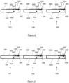
Figure 2 shows an enlarged view of first, downhole, part of the downhole assembly of the system shown inFigure 1 ; -
Figure 3 shows an enlarged view of second, uphole, part of the downhole assembly of the system shown inFigure 1 ; and -
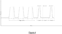
Figure 4 shows a graph showing an example of the first pressure signature and the second pressure signature used to remotely signal one or more selected downhole tool of the downhole assembly shown inFigures 1 and2 . - Referring first to
Figure 1 of the accompanying drawings, there is shown asystem 10 for remotely signalling adownhole assembly 12 comprising a number ofdownhole tools - As shown in
Figure 1 , the illustratedsystem 10 includes a subsea wellbore 16 extending from awellhead 18 disposed at the seabed S. Avalve arrangement 20, which in the illustratedsystem 10 takes the form of a Christmas tree, is disposed on thewellhead 18 and communicates with surface via amarine riser 22. - While the illustrated
system 10 takes the form of asubsea system 10, it will be understood that thesystem 10 may take any suitable form, whether subsea or onshore. - As also shown in
Figure 1 , thevalve arrangement 20 comprises achoke arrangement 24 configured to control production fluid flow from thewellbore 18. In the illustratedsystem 10, thechoke arrangement 24 comprises an adjustable choke having a valve member movable relative to a valve seat so as to vary the area of a flow passage defined therebetween. The area of the flow passage is reduced by moving the valve member of thechoke arrangement 24 towards the valve seat, the resultant reduction in the area of the flow passage causing an increase in pressure in the production fluid. The area of the flow passage is increased by moving the valve member of thechoke arrangement 24 away from the valve seat, the resultant increase in the area of the flow passage causing a decrease in pressure in the production fluid. - As will be described further below, the
choke arrangement 24 is operable to relay a trigger signal to thedownhole assembly 12 and a command signal for initiating operation of a selected one or more downhole tool of thedownhole assembly 12. - In the illustrated
system 10 shown inFigure 1 , thedownhole assembly 12 takes the form of a completion string, with a number of thedownhole tools downhole tools - The
downhole assembly 12 further comprisesbarrier members 26, which in the illustratedsystem 10 comprise packers, for isolating portions of the annulus A between theassembly 12 and the wellbore 16 to facilitate zonal isolation of the formation zones FZ1,FZ2, and facilitate ingress of production fluid into theassembly 12 via thedownhole tools - Referring now also to
Figures 2 and 3 of the accompanying drawings, which shows an enlarged view of part of thedownhole assembly 12 shown inFigure 1 , it can be seen that thedownhole tools body lateral flow passage downhole assembly 12 and avalve member lateral flow passage - In the illustrated
downhole tools valve members - The
downhole tools downhole assembly 12 is permitted and a second, closed, configuration in which production fluid ingress is prevented or at least restricted. - As shown in
Figures 2 and 3 , each of thedownhole tools system 10, theactuation arrangements actuation piston pistons respective valve member downhole tool - As also shown in
Figures 2 and 3 , each of thedownhole tools sensor arrangements more pressure gauge - As shown in
Figures 2 and 3 , each of thedownhole tools controllers sensor arrangements actuation arrangements valve members - As described above, the
choke arrangement 24 is operable to relay a trigger signal to thedownhole assembly 12 in the form of a first pressure signature imparted into the production fluid flow and a command signal for initiating operation of a selected one or more downhole tool of thedownhole assembly 12 in the form of a second pressure signature imparted into the production fluid flow. - Referring now also to
Figure 4 of the accompanying drawings, there is shown an example of the trigger signal and command signal used to operatedownhole tools downhole assembly 12. - As shown in
Figure 4 , the trigger signal takes the form of a first pressure signature comprising three pressure pulses produced by adjusting thechoke arrangement 24 as described above. In the illustratedsystem 10, the first pressure signature comprises a first pressure signal, a second pressure signal and a third pressure signal. The first pressure signal takes the form of a predetermined increase in fluid pressure of the production fluid flow maintained for a predetermined time period followed by a predetermined decrease in the fluid pressure of the production fluid flow. The second first pressure signal is identical to the first pressure signal, taking the form of a predetermined increase in fluid pressure of the production fluid flow maintained for a predetermined time period followed by a predetermined decrease in fluid pressure of the production fluid flow. The third pressure signal is identical to the first and second pressure signals, taking the form of a predetermined increase in fluid pressure of the production fluid flow maintained for a predetermined time period followed by a predetermined decrease in fluid pressure of the production fluid flow. - The
sensor arrangements downhole tools downhole assembly 12 monitor - continuously or with sufficient sample rate to detect the trigger signal - the pressure of the production fluid flow, thecontrollers sensor arrangements - The
sensor arrangements downhole tools downhole assembly 12 continue to monitor - continuously or with sufficient sample rate - the pressure of the production fluid flow,controllers sensor arrangements - The command signal takes the form of a second pressure signature in the production fluid flow at a predetermined time period following the first pressure signature. As shown in
Figure 4 , the second pressure signature comprises two pressure pulses at a time interval with corresponds to thedownhole tools - On detecting the second pressure signature, which will vary depending on which of the
downhole tools 14A has been selected to operate, thecontrollers system 10, thecontrollers respective actuation arrangements downhole tools controllers actuation arrangements 34B,34D34E34F to remain in their present state. Thecontrollers - In order to determine which of the downhole tools is to be operated, and as shown in
Figure 2 , each of thedownhole tools tracer element - The
tracer elements system 10 thetracer elements - By detecting and/or analysing the
tracer elements downhole tool - It will be recognised that the method, assembly and system described above are merely exemplary and that various modifications may be made without departing from the scope of the claimed invention as defined by the appended claims.
- For example, while in the illustrated
system 10, each of thedownhole tools sensor arrangement downhole tools downhole tools - While in the illustrated
system 10, each of thedownhole tools actuation arrangement downhole tools downhole tools - While in the illustrated
system 10, each of thedownhole tools tracer element downhole tools downhole tools
Claims (15)
- A method for remotely signalling a downhole assembly (12) comprising one or more downhole tools (14A, 14B, 14C, 14D, 14E, 14F) located in a wellbore (16), the method comprising:detecting and/or analysing a tracer element (44A, 44B, 44C, 44D, 44E, 44F) associated with one or more of the downhole tools (14A, 14B, 14C, 14D, 14E, 14F) and which is transportable with a production fluid flow from the wellbore (16);determining from said tracer element (44A, 44B, 44C, 44D, 44E, 44F) which of said one or more downhole tools (14A, 14B, 14C, 14D, 14E, 14F) of the downhole assembly (12) is to receive a command signal for initiating its operation; and thenoperating a choke arrangement (24) configured to control production fluid flow from the wellbore (16) to produce a trigger signal for the determined one or more downhole tools (14A, 14B, 14C, 14D, 14E, 14F) of the downhole assembly (12),wherein the trigger signal takes the form of a first pressure signature comprising at least a first pressure signal and a second pressure signal in the production fluid flow in the downhole assembly (12); andoperating the choke arrangement (24) to produce the command signal for initiating the operation of the determined one or more of the downhole tools (14A, 14B, 14C, 14D, 14E, 14F), wherein the command signal takes the form of a second pressure signature in the production fluid flow in the downhole assembly (12) at a predetermined time period following the first pressure signature.
- The method of claim 1, comprising detecting the first pressure signature and the second pressure signature using a downhole sensor arrangement (38A, 38B, 38C, 38D, 38E, 38F) forming part of, coupled to or operatively associated with one or more of the downhole tools (14A, 14B, 14C, 14D, 14E, 14F) of the downhole assembly (12).
- The method of claim 1 or 2, comprising operating the determined one or more downhole tools (14A, 14B, 14C, 14D, 14E, 14F) in response to the detected command signal.
- The method of any preceding claim, wherein at least one of the first pressure signal and the second pressure signal comprises or takes the form of at least one of:a predetermined increase in fluid pressure of the production fluid flow;a predetermined decrease in fluid pressure of the production fluid flow; a static fluid pressure of the production fluid flow.
- The method of any preceding claim, wherein the first pressure signature comprises n pressure signals, where n ≥ 2.
- The method of any preceding claim, wherein the or each downhole tool (14A, 14B, 14C, 14D, 14E, 14F) is operatively associated with a particular predetermined time period following the first pressure signature.
- The method of any preceding claim, wherein the second pressure signature comprises a first pressure signal at a first predetermined time following the first pressure signature, the first pressure signal comprising at least one of:a predetermined increase in fluid pressure of the production fluid flowa predetermined decrease in fluid pressure of the production fluid flow;a static fluid pressure of the production fluid flow.
- The method of claim 7, wherein the second pressure signature comprises a second pressure signal at a second predetermined time following the first pressure signature, the second pressure signal comprising at least one of:a predetermined increase in fluid pressure of the production fluid flowa predetermined decrease in fluid pressure of the production fluid flow;a static fluid pressure of the production fluid flow.
- The method of any preceding claim, wherein the second pressure signature comprises n number of pressure signals, where n ≥ 1.
- The method of any preceding claim, comprising operating the choke arrangement (24) to at least one of:increase the pressure of the production fluid flow;decrease the pressure of the production fluid flow;provide a static pressure of the production fluid flow.
- A system (10) comprising:a downhole assembly (12) comprising:one or more downhole tools (14A, 14B, 14C, 14D, 14E, 14F) for location in a wellbore (16);a sensor arrangement (38A, 38B, 38C, 38D, 38E, 38F) forming part of, coupled to or operatively associated with the one or more downhole tools (14A, 14B, 14C, 14D, 14E, 14F),wherein the sensor arrangement (38A, 38B, 38C, 38D, 38E, 38F) is configured to detect a trigger signal for a determined one or more downhole tools (14A, 14B, 14C, 14D, 14E, 14F) of the downhole assembly (12), wherein the trigger signal takes the form of a first pressure signature comprising at least a first pressure signal and a second pressure signal in a production fluid flow in the downhole assembly (12),and wherein the sensor arrangement (38A, 38B, 38C, 38D, 38E, 38F) is configured to detect a command signal for initiating operation of the determined one or more of the downhole tools (14A, 14B, 14C, 14D, 14E, 14F), wherein the command signal takes the form of a second pressure signature in the production fluid flow in the downhole assembly (12);an actuation arrangement (34A, 34B, 34C, 34D, 34E, 34F) forming part of, coupled to or operatively associated with the one or more downhole tools (14A, 14B, 14C, 14D, 14E, 14F),wherein the actuation arrangement (34A, 34B, 34C, 34D, 34E, 34F) is configured to initiate operation of the selected one or more downhole tool (14A, 14B, 14C, 14D, 14E, 14F) of the downhole assembly (12) in response to the command signal; anda tracer element disposed on, coupled to, forming part of and/or operatively associated with the one or more downhole tools (14A, 14B, 14C, 14D, 14E, 14F),wherein the tracer element is configured to be transported towards surface with the production fluid flow; anda choke arrangement (24) configured to control the production fluid flow from the wellbore (16),wherein the choke arrangement (24) is configurable to produce the first pressure signature in the production fluid flow,and wherein the choke arrangement (24) is configurable to produce the second pressure signature in the production fluid flow at a predetermined time period following the first pressure signature, andwherein the system (10) is configured to determine which of said one or more downhole tools (14A, 14B, 14C, 14D, 14E, 14F) of the downhole assembly (12) is to receive the command signal by detecting and/or analysing the tracer element associated with one or more of the downhole tools (14A, 14B, 14C, 14D, 14E, 14F).
- The system (10) of claim 11, wherein the choke arrangement (24) comprises or forms part of a surface choke arrangement.
- The system (10) of claim 11 or 12, wherein part of the choke arrangement (24) is disposed downhole.
- The system (10) of any one of claims 11 to 13, wherein the tracer element is soluble and/or dispersable in contact with a selected fluid, for example water or hydrocarbons.
- The system (10) of any one of claims 11 to 14, wherein the one or more downhole tools (14A, 14B, 14C, 14D, 14E, 14F) comprises a downhole flow control device.
Applications Claiming Priority (2)
| Application Number | Priority Date | Filing Date | Title |
|---|---|---|---|
| GB2014518.1A GB2598797B (en) | 2020-09-15 | 2020-09-15 | Method and system for remotely signalling a downhole assembly comprising one or more downhole tool |
| PCT/GB2021/052377 WO2022058722A1 (en) | 2020-09-15 | 2021-09-14 | Method and system for remotely signalling a downhole assembly comprising one or more downhole tool |
Publications (2)
| Publication Number | Publication Date |
|---|---|
| EP4214396A1 EP4214396A1 (en) | 2023-07-26 |
| EP4214396B1 true EP4214396B1 (en) | 2024-07-10 |
Family
ID=73149599
Family Applications (1)
| Application Number | Title | Priority Date | Filing Date |
|---|---|---|---|
| EP21773646.1A Active EP4214396B1 (en) | 2020-09-15 | 2021-09-14 | Method and system for remotely signalling a downhole assembly comprising one or more downhole tool |
Country Status (7)
| Country | Link |
|---|---|
| US (1) | US12152486B2 (en) |
| EP (1) | EP4214396B1 (en) |
| AU (1) | AU2021344819B2 (en) |
| BR (1) | BR112023004798A2 (en) |
| CA (1) | CA3191824A1 (en) |
| GB (1) | GB2598797B (en) |
| WO (1) | WO2022058722A1 (en) |
Family Cites Families (21)
| Publication number | Priority date | Publication date | Assignee | Title |
|---|---|---|---|---|
| US4856595A (en) * | 1988-05-26 | 1989-08-15 | Schlumberger Technology Corporation | Well tool control system and method |
| US5355960A (en) | 1992-12-18 | 1994-10-18 | Halliburton Company | Pressure change signals for remote control of downhole tools |
| GB9314464D0 (en) | 1993-07-13 | 1993-08-25 | Buyers Mark | Trigger module |
| US5887657A (en) | 1995-02-09 | 1999-03-30 | Baker Hughes Incorporated | Pressure test method for permanent downhole wells and apparatus therefore |
| US6199629B1 (en) | 1997-09-24 | 2001-03-13 | Baker Hughes Incorporated | Computer controlled downhole safety valve system |
| US6041864A (en) * | 1997-12-12 | 2000-03-28 | Schlumberger Technology Corporation | Well isolation system |
| US6182764B1 (en) | 1998-05-27 | 2001-02-06 | Schlumberger Technology Corporation | Generating commands for a downhole tool using a surface fluid loop |
| US6712160B1 (en) * | 2000-11-07 | 2004-03-30 | Halliburton Energy Services Inc. | Leadless sub assembly for downhole detection system |
| US6920085B2 (en) * | 2001-02-14 | 2005-07-19 | Halliburton Energy Services, Inc. | Downlink telemetry system |
| US7026950B2 (en) | 2003-03-12 | 2006-04-11 | Varco I/P, Inc. | Motor pulse controller |
| GB2403488B (en) | 2003-07-04 | 2005-10-05 | Flight Refueling Ltd | Downhole data communication |
| US7171309B2 (en) | 2003-10-24 | 2007-01-30 | Schlumberger Technology Corporation | Downhole tool controller using autocorrelation of command sequences |
| GB0411121D0 (en) | 2004-05-19 | 2004-06-23 | Omega Completion Technology | Method for signalling a downhole device in a flowing well |
| US7337850B2 (en) * | 2005-09-14 | 2008-03-04 | Schlumberger Technology Corporation | System and method for controlling actuation of tools in a wellbore |
| GB0720421D0 (en) * | 2007-10-19 | 2007-11-28 | Petrowell Ltd | Method and apparatus for completing a well |
| US7775273B2 (en) * | 2008-07-25 | 2010-08-17 | Schlumberber Technology Corporation | Tool using outputs of sensors responsive to signaling |
| AU2013333712B2 (en) | 2012-10-16 | 2017-05-25 | Weatherford Technology Holdings, Llc | Flow control assembly |
| DK178108B1 (en) | 2014-03-14 | 2015-05-26 | Yellow Shark Holding Aps | Activation mechanism for a downhole tool and a method thereof |
| US20180106144A1 (en) * | 2016-10-14 | 2018-04-19 | Meduna Investments, LLC | Pinpointing Water Producing Zone During Multizone Production |
| US11255169B2 (en) * | 2017-02-13 | 2022-02-22 | Ncs Multistage Inc. | System and method for wireless control of well bore equipment |
| AU2017417486B2 (en) * | 2017-06-07 | 2023-08-17 | Halliburton Energy Services, Inc. | Downhole interventionless tools, systems, and methods for setting packers |
-
2020
- 2020-09-15 GB GB2014518.1A patent/GB2598797B/en active Active
-
2021
- 2021-09-14 US US18/042,218 patent/US12152486B2/en active Active
- 2021-09-14 EP EP21773646.1A patent/EP4214396B1/en active Active
- 2021-09-14 CA CA3191824A patent/CA3191824A1/en active Pending
- 2021-09-14 WO PCT/GB2021/052377 patent/WO2022058722A1/en not_active Ceased
- 2021-09-14 AU AU2021344819A patent/AU2021344819B2/en active Active
- 2021-09-14 BR BR112023004798A patent/BR112023004798A2/en unknown
Also Published As
| Publication number | Publication date |
|---|---|
| GB202014518D0 (en) | 2020-10-28 |
| EP4214396A1 (en) | 2023-07-26 |
| US12152486B2 (en) | 2024-11-26 |
| BR112023004798A2 (en) | 2023-04-18 |
| AU2021344819B2 (en) | 2026-05-07 |
| GB2598797B (en) | 2023-07-12 |
| AU2021344819A1 (en) | 2023-04-06 |
| CA3191824A1 (en) | 2022-03-24 |
| US20230323767A1 (en) | 2023-10-12 |
| WO2022058722A1 (en) | 2022-03-24 |
| GB2598797A (en) | 2022-03-16 |
Similar Documents
| Publication | Publication Date | Title |
|---|---|---|
| EP2318645B1 (en) | A tool using outputs of sensors responsive to signaling | |
| EP1669541B1 (en) | Locating joins in coiled tubing operations | |
| US7543641B2 (en) | System and method for controlling wellbore pressure during gravel packing operations | |
| US9051810B1 (en) | Frac valve with ported sleeve | |
| US8757265B1 (en) | Frac valve | |
| US10584563B2 (en) | Remotely operated and multi-functional down-hole control tools | |
| US6041864A (en) | Well isolation system | |
| US10233725B2 (en) | Downhole system having isolation flow valve and method | |
| US9371714B2 (en) | Downhole smart control system | |
| EP0584997A2 (en) | Downhole tool operating system and method | |
| AU2018456049B2 (en) | Remote-open barrier valve | |
| US11078769B2 (en) | Multi stage chemical injection | |
| US11649692B2 (en) | System and method for cementing a wellbore | |
| WO2022146492A1 (en) | Reverse cementing tool | |
| US11566490B2 (en) | Gravel pack service tool used to set a packer | |
| EP0500343B1 (en) | Downhole tool with hydraulic actuating system | |
| EP3559395B1 (en) | Staged annular restriction for managed pressure drilling | |
| AU2021344819B2 (en) | Method and system for remotely signalling a downhole assembly comprising one or more downhole tool | |
| EP2576957B1 (en) | System and method for passing matter in a flow passage | |
| US20250369308A1 (en) | System for control and treatment in a well | |
| US20090139714A1 (en) | Interventionless pinpoint completion and treatment | |
| GB2474560A (en) | Fluid logic tool for use in a well |
Legal Events
| Date | Code | Title | Description |
|---|---|---|---|
| STAA | Information on the status of an ep patent application or granted ep patent |
Free format text: STATUS: UNKNOWN |
|
| STAA | Information on the status of an ep patent application or granted ep patent |
Free format text: STATUS: THE INTERNATIONAL PUBLICATION HAS BEEN MADE |
|
| PUAI | Public reference made under article 153(3) epc to a published international application that has entered the european phase |
Free format text: ORIGINAL CODE: 0009012 |
|
| STAA | Information on the status of an ep patent application or granted ep patent |
Free format text: STATUS: REQUEST FOR EXAMINATION WAS MADE |
|
| 17P | Request for examination filed |
Effective date: 20230215 |
|
| AK | Designated contracting states |
Kind code of ref document: A1 Designated state(s): AL AT BE BG CH CY CZ DE DK EE ES FI FR GB GR HR HU IE IS IT LI LT LU LV MC MK MT NL NO PL PT RO RS SE SI SK SM TR |
|
| P01 | Opt-out of the competence of the unified patent court (upc) registered |
Effective date: 20230908 |
|
| DAV | Request for validation of the european patent (deleted) | ||
| DAX | Request for extension of the european patent (deleted) | ||
| GRAP | Despatch of communication of intention to grant a patent |
Free format text: ORIGINAL CODE: EPIDOSNIGR1 |
|
| STAA | Information on the status of an ep patent application or granted ep patent |
Free format text: STATUS: GRANT OF PATENT IS INTENDED |
|
| INTG | Intention to grant announced |
Effective date: 20240207 |
|
| GRAS | Grant fee paid |
Free format text: ORIGINAL CODE: EPIDOSNIGR3 |
|
| GRAA | (expected) grant |
Free format text: ORIGINAL CODE: 0009210 |
|
| STAA | Information on the status of an ep patent application or granted ep patent |
Free format text: STATUS: THE PATENT HAS BEEN GRANTED |
|
| AK | Designated contracting states |
Kind code of ref document: B1 Designated state(s): AL AT BE BG CH CY CZ DE DK EE ES FI FR GB GR HR HU IE IS IT LI LT LU LV MC MK MT NL NO PL PT RO RS SE SI SK SM TR |
|
| REG | Reference to a national code |
Ref country code: CH Ref legal event code: EP |
|
| REG | Reference to a national code |
Ref country code: DE Ref legal event code: R096 Ref document number: 602021015577 Country of ref document: DE |
|
| REG | Reference to a national code |
Ref country code: LT Ref legal event code: MG9D |
|
| REG | Reference to a national code |
Ref country code: NL Ref legal event code: MP Effective date: 20240710 |
|
| PG25 | Lapsed in a contracting state [announced via postgrant information from national office to epo] |
Ref country code: PT Free format text: LAPSE BECAUSE OF FAILURE TO SUBMIT A TRANSLATION OF THE DESCRIPTION OR TO PAY THE FEE WITHIN THE PRESCRIBED TIME-LIMIT Effective date: 20241111 |
|
| REG | Reference to a national code |
Ref country code: AT Ref legal event code: MK05 Ref document number: 1702177 Country of ref document: AT Kind code of ref document: T Effective date: 20240710 |
|
| PG25 | Lapsed in a contracting state [announced via postgrant information from national office to epo] |
Ref country code: NL Free format text: LAPSE BECAUSE OF FAILURE TO SUBMIT A TRANSLATION OF THE DESCRIPTION OR TO PAY THE FEE WITHIN THE PRESCRIBED TIME-LIMIT Effective date: 20240710 |
|
| PG25 | Lapsed in a contracting state [announced via postgrant information from national office to epo] |
Ref country code: PT Free format text: LAPSE BECAUSE OF FAILURE TO SUBMIT A TRANSLATION OF THE DESCRIPTION OR TO PAY THE FEE WITHIN THE PRESCRIBED TIME-LIMIT Effective date: 20241111 Ref country code: NL Free format text: LAPSE BECAUSE OF FAILURE TO SUBMIT A TRANSLATION OF THE DESCRIPTION OR TO PAY THE FEE WITHIN THE PRESCRIBED TIME-LIMIT Effective date: 20240710 |
|
| PG25 | Lapsed in a contracting state [announced via postgrant information from national office to epo] |
Ref country code: FI Free format text: LAPSE BECAUSE OF FAILURE TO SUBMIT A TRANSLATION OF THE DESCRIPTION OR TO PAY THE FEE WITHIN THE PRESCRIBED TIME-LIMIT Effective date: 20240710 Ref country code: GR Free format text: LAPSE BECAUSE OF FAILURE TO SUBMIT A TRANSLATION OF THE DESCRIPTION OR TO PAY THE FEE WITHIN THE PRESCRIBED TIME-LIMIT Effective date: 20241011 Ref country code: PL Free format text: LAPSE BECAUSE OF FAILURE TO SUBMIT A TRANSLATION OF THE DESCRIPTION OR TO PAY THE FEE WITHIN THE PRESCRIBED TIME-LIMIT Effective date: 20240710 |
|
| PG25 | Lapsed in a contracting state [announced via postgrant information from national office to epo] |
Ref country code: BG Free format text: LAPSE BECAUSE OF FAILURE TO SUBMIT A TRANSLATION OF THE DESCRIPTION OR TO PAY THE FEE WITHIN THE PRESCRIBED TIME-LIMIT Effective date: 20240710 |
|
| PG25 | Lapsed in a contracting state [announced via postgrant information from national office to epo] |
Ref country code: LV Free format text: LAPSE BECAUSE OF FAILURE TO SUBMIT A TRANSLATION OF THE DESCRIPTION OR TO PAY THE FEE WITHIN THE PRESCRIBED TIME-LIMIT Effective date: 20240710 |
|
| PG25 | Lapsed in a contracting state [announced via postgrant information from national office to epo] |
Ref country code: AT Free format text: LAPSE BECAUSE OF FAILURE TO SUBMIT A TRANSLATION OF THE DESCRIPTION OR TO PAY THE FEE WITHIN THE PRESCRIBED TIME-LIMIT Effective date: 20240710 Ref country code: IS Free format text: LAPSE BECAUSE OF FAILURE TO SUBMIT A TRANSLATION OF THE DESCRIPTION OR TO PAY THE FEE WITHIN THE PRESCRIBED TIME-LIMIT Effective date: 20241110 |
|
| PG25 | Lapsed in a contracting state [announced via postgrant information from national office to epo] |
Ref country code: HR Free format text: LAPSE BECAUSE OF FAILURE TO SUBMIT A TRANSLATION OF THE DESCRIPTION OR TO PAY THE FEE WITHIN THE PRESCRIBED TIME-LIMIT Effective date: 20240710 |
|
| PG25 | Lapsed in a contracting state [announced via postgrant information from national office to epo] |
Ref country code: ES Free format text: LAPSE BECAUSE OF FAILURE TO SUBMIT A TRANSLATION OF THE DESCRIPTION OR TO PAY THE FEE WITHIN THE PRESCRIBED TIME-LIMIT Effective date: 20240710 Ref country code: RS Free format text: LAPSE BECAUSE OF FAILURE TO SUBMIT A TRANSLATION OF THE DESCRIPTION OR TO PAY THE FEE WITHIN THE PRESCRIBED TIME-LIMIT Effective date: 20241010 |
|
| PG25 | Lapsed in a contracting state [announced via postgrant information from national office to epo] |
Ref country code: RS Free format text: LAPSE BECAUSE OF FAILURE TO SUBMIT A TRANSLATION OF THE DESCRIPTION OR TO PAY THE FEE WITHIN THE PRESCRIBED TIME-LIMIT Effective date: 20241010 Ref country code: PL Free format text: LAPSE BECAUSE OF FAILURE TO SUBMIT A TRANSLATION OF THE DESCRIPTION OR TO PAY THE FEE WITHIN THE PRESCRIBED TIME-LIMIT Effective date: 20240710 Ref country code: LV Free format text: LAPSE BECAUSE OF FAILURE TO SUBMIT A TRANSLATION OF THE DESCRIPTION OR TO PAY THE FEE WITHIN THE PRESCRIBED TIME-LIMIT Effective date: 20240710 Ref country code: IS Free format text: LAPSE BECAUSE OF FAILURE TO SUBMIT A TRANSLATION OF THE DESCRIPTION OR TO PAY THE FEE WITHIN THE PRESCRIBED TIME-LIMIT Effective date: 20241110 Ref country code: HR Free format text: LAPSE BECAUSE OF FAILURE TO SUBMIT A TRANSLATION OF THE DESCRIPTION OR TO PAY THE FEE WITHIN THE PRESCRIBED TIME-LIMIT Effective date: 20240710 Ref country code: GR Free format text: LAPSE BECAUSE OF FAILURE TO SUBMIT A TRANSLATION OF THE DESCRIPTION OR TO PAY THE FEE WITHIN THE PRESCRIBED TIME-LIMIT Effective date: 20241011 Ref country code: FI Free format text: LAPSE BECAUSE OF FAILURE TO SUBMIT A TRANSLATION OF THE DESCRIPTION OR TO PAY THE FEE WITHIN THE PRESCRIBED TIME-LIMIT Effective date: 20240710 Ref country code: ES Free format text: LAPSE BECAUSE OF FAILURE TO SUBMIT A TRANSLATION OF THE DESCRIPTION OR TO PAY THE FEE WITHIN THE PRESCRIBED TIME-LIMIT Effective date: 20240710 Ref country code: BG Free format text: LAPSE BECAUSE OF FAILURE TO SUBMIT A TRANSLATION OF THE DESCRIPTION OR TO PAY THE FEE WITHIN THE PRESCRIBED TIME-LIMIT Effective date: 20240710 Ref country code: AT Free format text: LAPSE BECAUSE OF FAILURE TO SUBMIT A TRANSLATION OF THE DESCRIPTION OR TO PAY THE FEE WITHIN THE PRESCRIBED TIME-LIMIT Effective date: 20240710 |
|
| REG | Reference to a national code |
Ref country code: DE Ref legal event code: R119 Ref document number: 602021015577 Country of ref document: DE |
|
| PG25 | Lapsed in a contracting state [announced via postgrant information from national office to epo] |
Ref country code: DK Free format text: LAPSE BECAUSE OF FAILURE TO SUBMIT A TRANSLATION OF THE DESCRIPTION OR TO PAY THE FEE WITHIN THE PRESCRIBED TIME-LIMIT Effective date: 20240710 Ref country code: RO Free format text: LAPSE BECAUSE OF FAILURE TO SUBMIT A TRANSLATION OF THE DESCRIPTION OR TO PAY THE FEE WITHIN THE PRESCRIBED TIME-LIMIT Effective date: 20240710 Ref country code: SM Free format text: LAPSE BECAUSE OF FAILURE TO SUBMIT A TRANSLATION OF THE DESCRIPTION OR TO PAY THE FEE WITHIN THE PRESCRIBED TIME-LIMIT Effective date: 20240710 |
|
| PG25 | Lapsed in a contracting state [announced via postgrant information from national office to epo] |
Ref country code: MC Free format text: LAPSE BECAUSE OF FAILURE TO SUBMIT A TRANSLATION OF THE DESCRIPTION OR TO PAY THE FEE WITHIN THE PRESCRIBED TIME-LIMIT Effective date: 20240710 Ref country code: EE Free format text: LAPSE BECAUSE OF FAILURE TO SUBMIT A TRANSLATION OF THE DESCRIPTION OR TO PAY THE FEE WITHIN THE PRESCRIBED TIME-LIMIT Effective date: 20240710 |
|
| PG25 | Lapsed in a contracting state [announced via postgrant information from national office to epo] |
Ref country code: CZ Free format text: LAPSE BECAUSE OF FAILURE TO SUBMIT A TRANSLATION OF THE DESCRIPTION OR TO PAY THE FEE WITHIN THE PRESCRIBED TIME-LIMIT Effective date: 20240710 |
|
| PG25 | Lapsed in a contracting state [announced via postgrant information from national office to epo] |
Ref country code: SK Free format text: LAPSE BECAUSE OF FAILURE TO SUBMIT A TRANSLATION OF THE DESCRIPTION OR TO PAY THE FEE WITHIN THE PRESCRIBED TIME-LIMIT Effective date: 20240710 Ref country code: IT Free format text: LAPSE BECAUSE OF FAILURE TO SUBMIT A TRANSLATION OF THE DESCRIPTION OR TO PAY THE FEE WITHIN THE PRESCRIBED TIME-LIMIT Effective date: 20240710 |
|
| REG | Reference to a national code |
Ref country code: CH Ref legal event code: PL |
|
| PLBE | No opposition filed within time limit |
Free format text: ORIGINAL CODE: 0009261 |
|
| STAA | Information on the status of an ep patent application or granted ep patent |
Free format text: STATUS: NO OPPOSITION FILED WITHIN TIME LIMIT |
|
| PG25 | Lapsed in a contracting state [announced via postgrant information from national office to epo] |
Ref country code: LU Free format text: LAPSE BECAUSE OF NON-PAYMENT OF DUE FEES Effective date: 20240914 |
|
| 26N | No opposition filed |
Effective date: 20250411 |
|
| PG25 | Lapsed in a contracting state [announced via postgrant information from national office to epo] |
Ref country code: DE Free format text: LAPSE BECAUSE OF NON-PAYMENT OF DUE FEES Effective date: 20250401 |
|
| REG | Reference to a national code |
Ref country code: BE Ref legal event code: MM Effective date: 20240930 |
|
| PG25 | Lapsed in a contracting state [announced via postgrant information from national office to epo] |
Ref country code: BE Free format text: LAPSE BECAUSE OF NON-PAYMENT OF DUE FEES Effective date: 20240930 |
|
| PG25 | Lapsed in a contracting state [announced via postgrant information from national office to epo] |
Ref country code: FR Free format text: LAPSE BECAUSE OF NON-PAYMENT OF DUE FEES Effective date: 20240930 |
|
| PG25 | Lapsed in a contracting state [announced via postgrant information from national office to epo] |
Ref country code: CH Free format text: LAPSE BECAUSE OF NON-PAYMENT OF DUE FEES Effective date: 20240930 |
|
| PG25 | Lapsed in a contracting state [announced via postgrant information from national office to epo] |
Ref country code: IE Free format text: LAPSE BECAUSE OF NON-PAYMENT OF DUE FEES Effective date: 20240914 |
|
| PG25 | Lapsed in a contracting state [announced via postgrant information from national office to epo] |
Ref country code: SE Free format text: LAPSE BECAUSE OF FAILURE TO SUBMIT A TRANSLATION OF THE DESCRIPTION OR TO PAY THE FEE WITHIN THE PRESCRIBED TIME-LIMIT Effective date: 20240710 |
|
| PGFP | Annual fee paid to national office [announced via postgrant information from national office to epo] |
Ref country code: NO Payment date: 20250909 Year of fee payment: 5 |
|
| PGFP | Annual fee paid to national office [announced via postgrant information from national office to epo] |
Ref country code: GB Payment date: 20250703 Year of fee payment: 5 |
|
| PG25 | Lapsed in a contracting state [announced via postgrant information from national office to epo] |
Ref country code: CY Free format text: LAPSE BECAUSE OF FAILURE TO SUBMIT A TRANSLATION OF THE DESCRIPTION OR TO PAY THE FEE WITHIN THE PRESCRIBED TIME-LIMIT; INVALID AB INITIO Effective date: 20210914 |
|
| PG25 | Lapsed in a contracting state [announced via postgrant information from national office to epo] |
Ref country code: HU Free format text: LAPSE BECAUSE OF FAILURE TO SUBMIT A TRANSLATION OF THE DESCRIPTION OR TO PAY THE FEE WITHIN THE PRESCRIBED TIME-LIMIT; INVALID AB INITIO Effective date: 20210914 |
|
| PG25 | Lapsed in a contracting state [announced via postgrant information from national office to epo] |
Ref country code: TR Free format text: LAPSE BECAUSE OF FAILURE TO SUBMIT A TRANSLATION OF THE DESCRIPTION OR TO PAY THE FEE WITHIN THE PRESCRIBED TIME-LIMIT Effective date: 20240710 |
|
| PG25 | Lapsed in a contracting state [announced via postgrant information from national office to epo] |
Ref country code: SI Free format text: LAPSE BECAUSE OF FAILURE TO SUBMIT A TRANSLATION OF THE DESCRIPTION OR TO PAY THE FEE WITHIN THE PRESCRIBED TIME-LIMIT Effective date: 20240710 |
|
| PG25 | Lapsed in a contracting state [announced via postgrant information from national office to epo] |
Ref country code: LT Free format text: LAPSE BECAUSE OF FAILURE TO SUBMIT A TRANSLATION OF THE DESCRIPTION OR TO PAY THE FEE WITHIN THE PRESCRIBED TIME-LIMIT Effective date: 20240710 |