EP4213898B1 - A sanitiser - Google Patents
A sanitiser Download PDFInfo
- Publication number
- EP4213898B1 EP4213898B1 EP21778207.7A EP21778207A EP4213898B1 EP 4213898 B1 EP4213898 B1 EP 4213898B1 EP 21778207 A EP21778207 A EP 21778207A EP 4213898 B1 EP4213898 B1 EP 4213898B1
- Authority
- EP
- European Patent Office
- Prior art keywords
- outlet
- plasma
- sanitiser
- user
- controller
- Prior art date
- Legal status (The legal status is an assumption and is not a legal conclusion. Google has not performed a legal analysis and makes no representation as to the accuracy of the status listed.)
- Active
Links
Images




Classifications
-
- A—HUMAN NECESSITIES
- A61—MEDICAL OR VETERINARY SCIENCE; HYGIENE
- A61L—METHODS OR APPARATUS FOR STERILISING MATERIALS OR OBJECTS IN GENERAL; DISINFECTION, STERILISATION OR DEODORISATION OF AIR; CHEMICAL ASPECTS OF BANDAGES, DRESSINGS, ABSORBENT PADS OR SURGICAL ARTICLES; MATERIALS FOR BANDAGES, DRESSINGS, ABSORBENT PADS OR SURGICAL ARTICLES
- A61L2/00—Disinfection or sterilisation of materials or objects, in general; Accessories therefor
- A61L2/16—Disinfection or sterilisation of materials or objects, in general; Accessories therefor using chemical substances
-
- A—HUMAN NECESSITIES
- A47—FURNITURE; DOMESTIC ARTICLES OR APPLIANCES; COFFEE MILLS; SPICE MILLS; SUCTION CLEANERS IN GENERAL
- A47K—SANITARY EQUIPMENT; ACCESSORIES THEREFOR, e.g. TOILET ACCESSORIES
- A47K10/00—Body-drying implements; Toilet paper; Holders therefor
- A47K10/48—Drying by means of hot air
-
- A—HUMAN NECESSITIES
- A61—MEDICAL OR VETERINARY SCIENCE; HYGIENE
- A61L—METHODS OR APPARATUS FOR STERILISING MATERIALS OR OBJECTS IN GENERAL; DISINFECTION, STERILISATION OR DEODORISATION OF AIR; CHEMICAL ASPECTS OF BANDAGES, DRESSINGS, ABSORBENT PADS OR SURGICAL ARTICLES; MATERIALS FOR BANDAGES, DRESSINGS, ABSORBENT PADS OR SURGICAL ARTICLES
- A61L2/00—Disinfection or sterilisation of materials or objects, in general; Accessories therefor
- A61L2/02—Disinfection or sterilisation of materials or objects, in general; Accessories therefor using physical processes
- A61L2/14—Plasma, i.e. ionised gases
-
- A—HUMAN NECESSITIES
- A61—MEDICAL OR VETERINARY SCIENCE; HYGIENE
- A61L—METHODS OR APPARATUS FOR STERILISING MATERIALS OR OBJECTS IN GENERAL; DISINFECTION, STERILISATION OR DEODORISATION OF AIR; CHEMICAL ASPECTS OF BANDAGES, DRESSINGS, ABSORBENT PADS OR SURGICAL ARTICLES; MATERIALS FOR BANDAGES, DRESSINGS, ABSORBENT PADS OR SURGICAL ARTICLES
- A61L9/00—Disinfection, sterilisation or deodorisation of air
- A61L9/16—Disinfection, sterilisation or deodorisation of air using physical phenomena
- A61L9/22—Ionisation
-
- A—HUMAN NECESSITIES
- A61—MEDICAL OR VETERINARY SCIENCE; HYGIENE
- A61L—METHODS OR APPARATUS FOR STERILISING MATERIALS OR OBJECTS IN GENERAL; DISINFECTION, STERILISATION OR DEODORISATION OF AIR; CHEMICAL ASPECTS OF BANDAGES, DRESSINGS, ABSORBENT PADS OR SURGICAL ARTICLES; MATERIALS FOR BANDAGES, DRESSINGS, ABSORBENT PADS OR SURGICAL ARTICLES
- A61L2103/00—Materials or objects being the target of disinfection or sterilisation
- A61L2103/05—Living organisms or biological materials
-
- A—HUMAN NECESSITIES
- A61—MEDICAL OR VETERINARY SCIENCE; HYGIENE
- A61L—METHODS OR APPARATUS FOR STERILISING MATERIALS OR OBJECTS IN GENERAL; DISINFECTION, STERILISATION OR DEODORISATION OF AIR; CHEMICAL ASPECTS OF BANDAGES, DRESSINGS, ABSORBENT PADS OR SURGICAL ARTICLES; MATERIALS FOR BANDAGES, DRESSINGS, ABSORBENT PADS OR SURGICAL ARTICLES
- A61L2202/00—Aspects relating to methods or apparatus for disinfecting or sterilising materials or objects
- A61L2202/10—Apparatus features
- A61L2202/11—Apparatus for generating biocidal substances, e.g. vaporisers, UV lamps
-
- A—HUMAN NECESSITIES
- A61—MEDICAL OR VETERINARY SCIENCE; HYGIENE
- A61L—METHODS OR APPARATUS FOR STERILISING MATERIALS OR OBJECTS IN GENERAL; DISINFECTION, STERILISATION OR DEODORISATION OF AIR; CHEMICAL ASPECTS OF BANDAGES, DRESSINGS, ABSORBENT PADS OR SURGICAL ARTICLES; MATERIALS FOR BANDAGES, DRESSINGS, ABSORBENT PADS OR SURGICAL ARTICLES
- A61L2202/00—Aspects relating to methods or apparatus for disinfecting or sterilising materials or objects
- A61L2202/10—Apparatus features
- A61L2202/14—Means for controlling sterilisation processes, data processing, presentation and storage means, e.g. sensors, controllers, programs
-
- A—HUMAN NECESSITIES
- A61—MEDICAL OR VETERINARY SCIENCE; HYGIENE
- A61L—METHODS OR APPARATUS FOR STERILISING MATERIALS OR OBJECTS IN GENERAL; DISINFECTION, STERILISATION OR DEODORISATION OF AIR; CHEMICAL ASPECTS OF BANDAGES, DRESSINGS, ABSORBENT PADS OR SURGICAL ARTICLES; MATERIALS FOR BANDAGES, DRESSINGS, ABSORBENT PADS OR SURGICAL ARTICLES
- A61L2202/00—Aspects relating to methods or apparatus for disinfecting or sterilising materials or objects
- A61L2202/10—Apparatus features
- A61L2202/15—Biocide distribution means, e.g. nozzles, pumps, manifolds, fans, baffles, sprayers
-
- A—HUMAN NECESSITIES
- A61—MEDICAL OR VETERINARY SCIENCE; HYGIENE
- A61L—METHODS OR APPARATUS FOR STERILISING MATERIALS OR OBJECTS IN GENERAL; DISINFECTION, STERILISATION OR DEODORISATION OF AIR; CHEMICAL ASPECTS OF BANDAGES, DRESSINGS, ABSORBENT PADS OR SURGICAL ARTICLES; MATERIALS FOR BANDAGES, DRESSINGS, ABSORBENT PADS OR SURGICAL ARTICLES
- A61L2209/00—Aspects relating to disinfection, sterilisation or deodorisation of air
- A61L2209/10—Apparatus features
- A61L2209/11—Apparatus for controlling air treatment
Definitions
- the present invention relates to a sanitising apparatus. More particularly to a sanitizing apparatus for sanitizing all or part of a user using plasma created by ultraviolet light. Aspects of the invention may be combined with a dryer system to create a combined drier/sanitiser.
- UV-C ultraviolet photocatalytic oxidation
- the Radic8 Viruskiller air purifier and the Sterillo TM Hand Dryer use UV-C and PCO to sterilise ambient air and surrounding surfaces however neither are capable of sanitising a user in a convenient time period.
- American Dryer's ExtremeAir TM CPC utilises as cold plasma generator claimed to produce hydroxyl ions that are expelled in the direction of a user at a claimed 221 mph, therefore it is questionable how effective ions at such a low concentration and high velocity are at sanitizing a user's hands.
- aspects and/or embodiments seek to provide sanitised and sanitising air and plasma for sanitizing a user and the ambient surroundings of the sanitiser. Further embodiments may also provide air for drying the user's hands.
- a sanitiser as defined in claim 1 is proposed.
- the reservoir can provide storage in which plasma can be accumulated to allow sufficient plasma to be directed to the user to effectively sanitise the user in an acceptable amount of time to the user.
- the plasma generator is contained within the reservoir to directly fill the reservoir with plasma when required.
- the first outlet towards the upper portion configured to direct plasma outwardly and downwardly can provide the advantage of the plasma being distributed around the environment in which the sanitiser is located. Thereby providing a sanitising effect on the air and surfaces in said environment.
- the sanitiser may include a drier. This provides the dual benefit of drying a user after washing and consuming the time required to build up sufficient plasma in the reservoir to sanitise the user.
- the drier may be a jet drier for creating a jet of air and may further include an outlet for directing said air towards a user.
- the second outlet of the reservoir may be positioned proximal to the drier outlet for directing plasma towards the user.
- the drier may include a heater for heating air and an outlet for directing said heated air to towards a user.
- the second outlet of the reservoir may be positioned proximal to the drier outlet for directing plasma towards the user.
- the second outlet from the reservoir may surround the drier outlet. Thereby providing no perceptible shift in the supply direction of the fluid provided to the user.
- the second outlet may include an outlet plenum comprising a plenum inlet and a plenum outlet.
- the plenum outlet may be offset from the inlet to slow the velocity and control the direction of plasma directed to the user. Thereby, providing increased contact between the user and the plasma provided by the machine and enhancing the sanitising effect.
- the controller may be operable in a first mode to cause the operation of the one or more fluid movers such as to cause the flow of plasma out of the first outlet alone. Therefore, advantageously sanitising the ambient surroundings of the sanitiser.
- the controller may be operable in a second mode to prevent operation of the one or more fluid movers such as to store plasma in said reservoir. Allowing a high quantity of dense plasma to be generated by the plasma generator to accumulate in the reservoir in preparation for sanitising a user in the manner described in the third or fourth modes below.
- controller may be operable in a third mode to cause the operation of the one or more fluid movers such as to cause the flow of plasma out of the second outlet alone.
- controller may be operable in a fourth mode to cause the operation of the one or more fluid movers such as to cause the flow of plasma out of both the first and second outlets simultaneously.
- the controller may be operably connected to the presence sensor and to the one or more fluid movers for ceasing the operation thereof and, thereby, preventing flow of plasma from said reservoir for a period of time upon the detection of a user. Therefore, allowing a contact free operation by the user and reducing the chance of transmission of pathogens by touch.
- the controller may be operably connected to the hand drier for detecting the operation thereof.
- the controller may be operably connected to the presence sensor and to the one or more fluid movers for allowing the flow of plasma from said reservoir out of said second outlet and towards the user upon cessation of the flow of air from the hand drier.
- controller may be operable upon receipt of a signal from the presence sensor to operate the one or more fluid movers to cause plasma to be directed out of said first outlet when no user is detected.
- the controller may be operable upon receipt of a signal from the presence sensor to operate the one or more fluid movers to cause plasma to be directed out of said first outlet when a user is detected.
- the one or more air movers may comprise one or more fans.
- a first fan of said one or more fans may be at the first outlet to the reservoir.
- a second fan of said one or more fans may be at the second of said outlets to the reservoir.
- the one or more fluid movers from the reservoir may comprise a single bi-directional fan.
- said one or more inlets to the reservoir may comprise one or other of the first and second outlets. Therefore, requiring fewer components and a simpler fluid flow through the sanitiser.
- the sanitiser may further include a timer that may be connected to the controller for causing the operation of the one or more fluid movers after the cessation of flow from the hand drier.
- the sanitiser may include a display for informing the user when the sanitising process is complete.
- the display may include a plurality of LEDs for indicating the time remaining until the sanitising process is complete. It is important that the full reservoir of plasma is directed at the user for the maximum sanitising effect. The display will clearly indicate to the user the relative time remaining until sanitising is complete to ensure the user remains for the full process.
- the sanitiser may include a gas sensor for detecting the concentration of a particular gas.
- the controller may be operably connected to the gas sensor.
- the controller may include a comparator for comparing a gas concentration threshold for the particular gas with the concentration of the particular gas detected by the gas sensor.
- the controller may be operable to activate or deactivate the plasma generator when the concentration of the particular gas is at or passes the gas concentration threshold.
- the controller may be operable to deactivate the plasma generator if the concentration of the particular gas is at or above the gas concentration threshold.
- the particular gas may be ozone.
- the gas sensor allows the dryer to respond to the changing concentration of gasses in the air.
- it is advantageous to control the concentration of ozone that can result from the super oxide ions created by the plasma generator.
- the sanitiser may be for sanitising the hands of a user.
- the drier may be a hand drier for drying the hands of a user.
- the sanitiser 10 may include a reservoir 30, connected to a plasma generator 20 (not shown in Figure 1 ) for generating plasma 22.
- One or more inlets 32 may be connected to the plasma generator 22.
- the reservoir 30 may have a first outlet 34 that may include a first duct 34A and a second outlet 36 that may include a second duct 36A, all are preferably fluidly connected to one or more inlets 32 for providing a passage for fluid from the one or more inlets 32 to outlets 34,36.
- the outlet 34 has a first end 34B connected to the reservoir 30 and a second end 34C open to the environment surrounding or outside the sanitiser 10.
- the two ends 34B, 34C may be connected by the duct 34A.
- the outlet 36 has a first end 36B connected to the reservoir 30 and a second end 36C open to the air surrounding or outside the sanitiser 10.
- the two ends 36B, 36C may be connected by the duct 36A.
- the reservoir 30 maybe sealed apart from the one or more inlets 32 and outlets 34,36 for collecting and storing plasma 22 generated by the plasma generator 20.
- the plasma 22 generated by the plasma generator 20 is in the form of a gaseous plasma 22.
- the fluid entering the one or more inlets 32 is air that is provided to the plasma generator 20 from which the plasma generator 20 generates plasma 22.
- plasma 22 is the fluid provided to and supplied by the outlets 34, 36 that may include a mixture of plasma 20 generated by the plasma generator 20 and air.
- the first outlet 34 of the reservoir 30 may further include a divergent outlet 38 for providing plasma 22 from the reservoir 30 to the external casing 12 and the ambient surroundings for sanitising the external casing 12, the air and ambient surroundings.
- the ambient surroundings may be the area local to the sanitiser 10 or the room in which the sanitiser 10 is located including the air and surfaces in the area.
- the second outlet 36 of the reservoir 30 may include the duct 36A connecting the first end 36B and the second end 36C for providing and directing plasma to a user to sanitise the user.
- the first outlet 34 may be situated in a first portion 14 of the sanitiser 10 and the second outlet 36 may be situated in a second portion of the sanitiser 10.
- the first outlet 34 may include a divergent outlet 38 that may be located towards the upper portion 14A of the sanitiser 10.
- the divergent outlet 38 directs plasma 22 outwardly and downwardly for sanitising the external casing and/or surroundings. It will be appreciated that whilst in Figure 1 the divergent outlet 38 of the first outlet 34 is paced towards the upper portion 14A of the sanitiser 10 the divergent outlet 38 can be placed at a lower portion 16B of the sanitiser or another point suitable for providing plasma 22 to the ambient surroundings.
- the second outlet 36 is situated in the second portion 16 of the sanitiser 10.
- the outlet 36 is in the lower portion 16A of the sanitiser 10 and specifically the base of the sanitiser 10, it will be appreciated the outlet 36 can be located in any location suitable for providing plasma 22 to the user for sanitising the user.
- the sanitiser 10 may supply plasma to the user for sanitising a user's hands.
- the embodiment of Figure 1 may include an optional drier 60 that may include a fan 66 and a motor 68 for supplying air to an outlet 64 for directing air to a user.
- the drier 50 shown in Figure 1 is a jet drier 60 that provides ambient temperature air at high velocity for drying the user.
- any other form of drier 60 including a hot air drier 60 further including a heater 62 may be used.
- the outlet of the drier 64 may be positioned proximal, next to or adjacent the second outlet 36 of the sanitiser 10 such that the user does not need to move, or must move only a very short distance, to receive the air from the drier 60 or the plasma 22 from the sanitiser 10.
- the second outlet 36 may surround the outlet of the drier 64 or visa-versa for directing plasma towards a user. Surrounding the outlet may be a coaxial arrangement, or a plurality of outlets 36, 64 surrounding a central outlet 36, 64. For Example the second outlet 36 may include two outlets either side of the drier outlet 64.
- the outlets 36, 64 may be configured to direct fluid in a convergent path in order to reduce the perceived difference between drying air and plasma 22 delivery or to better surround the user's hands with fluid for sanitising or drying.
- the drier 60 may be a hand drier 60.
- FIG 2 shows a similar embodiment of the sanitiser 10 of Figure 1 with the external cover 12 removed and the reservoir 30 removed. Removing the reservoir 30 exposes the plasma generator 20, the one or more inlets 32 and one or more fluid movers 40, 42. In the embodiment of figure 2 the plasma generator 20 may be contained within the reservoir 30, however may be remote from the reservoir 30.
- the plasma generator 20 may include an Ultraviolet light (UV) source 24 and photo-catalytic plates 26.
- UV has a dual effect. UV light, specifically short wavelength ultraviolet light known as UV-C kills or deactivates pathogens directly exposed to the UV light by destroying or disrupting their genetic material, therefore, sanitising the fluid that passes through the reservoir that is directly exposed to the UV light.
- the plasma generator 20 also generates plasma 22.
- the photo-catalytic plates 26 may include the material Titanium Dioxide, that when exposed to UV light cause water molecules in the air to oxidise to form Hydroxyl radicals and super oxide ions in the air. The Hydroxyl radicals have anti-bacterial and anti-viral effects by damaging the molecular structure of the pathogens.
- the super oxide ions cause small particles such as viruses to clump together and form clusters. Thus, removing them from the atmosphere.
- the advantage of the hydroxyl radicals and the super oxide ions are that they are effective outside of the sanitiser 10 in which they are created and permeate the ambient surroundings or room in which the sanitiser 10 is located and therefore sanitise the air and surfaces and the item or user that are external to the sanitiser 10.
- the purpose of the reservoir 30 is to create a mixture of air and plasma 22 with a high concentration of plasma 22, comprised of hydroxyl radicals and super oxide ions, to provide an improved sanitising effect for the user or item outside of the sanitiser 10.
- the sanitiser 10 may include one or more fluid movers 40, 42 for moving and directing fluid through the sanitiser 10.
- Figure 2 shows an embodiment with 2 fluid movers 40, 42.
- the first outlet 34 may include the first fluid mover 40 for supplying plasma 22 to the first outlet 34.
- the second outlet 36 may include the second air mover 42 for supplying plasma 22 to the second outlet 36.
- the embodiment of Figure 2 may also include a separate one or more inlets 32 connected to the plasma generator 20. Note a separate inlet 32 is not included in the embodiment of Figure 1 .
- a separate inlet 32 is not included in the embodiment of Figure 1 .
- the first fluid mover 40 when the first fluid mover 40 is supplying plasma 22 from the reservoir 30 to the outlet 34 air enters the outlet 36 and outlet 36 performs the function of the one or more inlets 32 and when the second fluid mover 42 is supplying plasma 22 to the outlet 36 air enters outlet 34 and outlet 34 preforms the function of the one or more inlets 32.
- the plasma generator 20 in the preferred embodiment of Figure 2 is contained within the reservoir 30 the plasma generator 20 may be contained within the inlet 32 or another position for generating plasma 22 to be stored in the reservoir 30 and outputs 34 and 36.
- a first fluid mover 40 may be located at the first outlet 34 of the reservoir 30 for causing flow of plasma 22 out of the first outlet 34.
- a second fluid mover 42 may be located at the second outlet 36 of the reservoir 30 for causing the flow of plasma 22 out of the second outlet 36.
- An alternative embodiment is envisaged wherein there is only one fluid mover 40, 42 for example only the first fluid mover 40 or the second fluid mover 42 for supplying plasma 22 to both the first outlet 34 and the second outlet 36.
- the fluid mover 40, 42 may be a bi-directional fluid mover 40C.
- the one or more fluid movers 40, 42 may include one or more fans 40A, 42A and one or more motors 40B, 42B for causing flow of air and/or plasma into or from outlets 34, 36 or one or more inlets 32.
- the fluid movers 40, 42 may each include a director 40D, 42D for obturating or partially obturating the outlets 34, 36 or the inlet 32 to prevent or impede flow of plasma from said outlets 34, 36 or the inlet 32.
- the first fluid mover 40 for supplying plasma 22 to the first outlet 34 supplies a low volume flow that may be suitably matched to the speed of plasma generation by the plasma generator 20 and the second fluid mover 42 may supply a higher volume of stored plasma 22 from the reservoir 30 to the second outlet 36. Therefore, the first fluid mover 40 may be smaller than the second fluid mover 42.
- a controller 50 comprising a timer 80, a presence sensor 70 and a gas sensor 72 are also visible in Figure 1 and Figure 2 .
- the timer 80 may also be separate from the controller 50.
- the timer 80, the sensor 70, the one or more air movers 40, 42 and the drier 60 if present are all communicatively and/or operatively connected to the controller 50.
- the controller 50 may be operably connected to the one or more fluid movers 40, 42 for causing the flow of plasma 22 from the reservoir 30 to one or both of the outlets 34 and 36.
- the controller 50 may be operably connected to the one or more air movers 40, 42 to prevent or not actively cause the flow of plasma 22 from the reservoir 30 and/or the outlets 34, 36.
- the controller 50 may be operably connected to the one or more air movers 40, 42 to prevent the flow of plasma 22 from the reservoir 30 by preventing operation of the one or more air movers 40, 42 or by causing the air movers 40, 42 to obturate or partially obturate both or either of the outlets 34 and 36.
- the controller 50 in response to a signal received from the presence sensor 70 indicating the present of the user may activate the timer 80 and cause any one or any combination of the above actions of the one or more air movers 40, 42 in response to one or more of a signal from the presence sensor 70 and information from the timer 80.
- the gas sensor 72 may be a gas concentration sensor 72.
- the gas sensor 72 may detect a particular gas or particular gases and send a signal to the controller 50 indicating the presence or concentration of that gas or gases to the controller 50.
- the controller 50 may include a gas concentration threshold for each particular gas and a comparator 52 for comparing the concentration of the particular gases with the threshold gas concentration and indicating to the controller 50 if the concentration of the particular gas exceeds the gas concentration threshold.
- the comparator 52 may also indicate to the controller 50 if the concentration is at or passes the threshold and in response the controller may control the plasma generator 20. Controlling the plasma generator 20 can include activating or deactivating the plasma generator 20.
- the controller 50 includes the concentration threshold and the comparator 52, their relative location is immaterial.
- the comparator 52 and the threshold may be included in the gas sensor 72.
- the controller 50 may deactivate the plasma generator 20; alternatively, if the comparator 52 sends a signal to the controller 50 indicating that the concentration of the particular gas has reached or exceeded the gas concentration threshold the controller 50 may deactivate the plasma generator. Once the particular gas is no longer detected, or the concentration of the gas falls below the threshold, the sensor 72 or the comparator 52 may signal the fact to the controller 50 and the controller 50 may activate the plasma generator 20.
- the sanitiser 10 may include closed loop control of the concentration of the particular gas.
- the gas sensor 72 may be located on the exterior of the sanitiser 10 for monitoring the ambient air surrounding the sanitiser 10 or it may be located on the inlet 37 of the sanitiser 10.
- the particular gas may be Ozone which can be produced as a result of the super oxide ions released by the sanitizer. Therefore, turning the plasma generator 20 on and off can regulate the concentration of Ozone gas.
- Figure 3 shows an alternative embodiment of the sanitizer 10 tilted back to display the second portion 16 that in this embodiment is the lower portion 16A.
- the embodiment of figure 3 is similar to the embodiment of figure 1 with the addition that the second outlet 36 includes an outlet plenum 37.
- the outlet plenum is a chamber for controlling the velocity of the plasma 22, supplied by the one or more fluid movers 40, 42 and directing it to the user.
- the outlet plenum 37 has an inlet 37A, a body 37B and an outlet 37C.
- the outlet 37C may be offset from the inlet 37A.
- the outlet 37C may be laterally offset from the inlet 37A and/or of greater area than the inlet 37A to reduce the output velocity of the plasma 22, deliver plasma 22 over a greater area and/or introduce turbulent flow in order to improve the distribution over the user to enhance the sanitising effect.
- the drier outlet 64 may be positioned in front of the second outlet 36 or visa-versa.
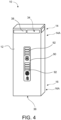
- Figure 4 shows the sanitiser 10 fully assembled in a preferred embodiment including an external casing 12 comprising an upper portion 14A, a lower portion 16A, and a display 90 for indicating to the user the proportion of time remaining until the sanitising process is complete, the time remaining and/or that sanitising is complete.
- the display 90 may be operably connected to one or more of the controller 50 and/or the timer 80.
- the display 90 may include a plurality of LEDs 92, wherein the proportion of time remaining until sanitising is complete is indicated by illuminated LEDs 92. Said LEDs 92 extinguishing in sequence as the time remaining diminishes.
- the display 90 may include a numerical count down. When a drier 60 is fitted the display 90 may include the time the drier 60 is active when displaying the time remaining.
- Figure 4 also shows the divergent outlet 38 of the first outlet 34 emerging in the upper portion 14A of the external case 12 however it will be understood that in alternative embodiments the first outlet may emerge towards the lower portion 16A or any other location suitable for providing plasma to the ambient surroundings for sanitising said ambient surroundings.
- the divergent outlet 38 has 4 apertures 38A but any number of apertures 38A is possible.
- the second outlet 36 emerges from the lower portion 16A of the external case 12 for supplying plasma 22 to a user, in particular from the base of the sanitiser 10. In other embodiments the second outlet 38 may emerge from any position suitable for sanitising the user.
- Figure 5 shows modes of operation of the sanitiser 10.
- the controller 50 may operate the one or more fluid movers 40, 42 to cause the flow of plasma out of the first outlet 34 alone for sanitising the ambient surroundings of the sanitiser 10. In a preferred embodiment the controller 50 activates the first fluid mover 40 to cause the flow of plasma out of the first outlet 34 alone. In the first mode air flows into the intake 32 and plasma 22 generated by the plasma generator 20 flows out of the first outlet 34. In a preferred embodiment the air flows into the intake 32 comprising the second outlet 36.
- the controller 50 may prevent operation of the one or more fluid movers 40, 42 thereby ceasing movement of fluid through the reservoir 30 and storing the plasma 22 generated by the plasma generator 20 in the reservoir 30.
- the controller 50 may cause the fluid movers 40, 42 to obturate the outlets 34, 36.
- the drier 60 may be activated by the controller 50 for drying the user.
- the reservoir 30 of the sanitiser 10 stores the plasma 20 generated by the plasma generator 20.
- plasma 22 is built up within the reservoir 30, to provide a high concentration of plasma 22 in the air and plasma mixture to provide an improved sanitising effect when the plasma 22 is directed at a user or item to be sanitised in the air outside of the sanitiser 10.
- the controller 50 activates the one or more fluid movers 40, 42 to cause the flow of plasma 22 out of the second outlet 36 alone, for sanitising the user after deactivating the dryer 60 if its operation is detected.
- the controller 50 activates the second fluid mover 42 to cause the flow of plasma out of the second outlet 36.
- the controller 50 may activate the one or more fluid movers 40, 42 to cause the flow of plasma 22 out of the first outlet 34 and the second outlet 36 simultaneously.
- controller 50 may activate the one or more fluid movers 40, 42 to cause the flow of plasma out of the second outlet 36 for sanitising the user and activate the drier 60 concurrently.
- the modes of operation can occur in any order under the control of the controller 50.
- the controller 50 on receiving a signal from the presence sensor 70, indicating the presence of a user has been detected, may cause the first mode, the second mode and the third mode or the second mode and third mode to occur in sequence or only the second mode for a period of time.
- the first mode may be a default or standby mode for sanitising the room or ambient surroundings of the sanitiser 10 to which the controller 50 returns the sanitiser 10 after being in other modes when no user is detected by the presence sensor 70.
- the controller 50 may cause the sanitiser 10 to move to the second mode to store plasma in preparation for sanitising the user and may further activate the timer 80.
- the controller 50 may cause the sanitizer 10 to move to the third mode once sufficient time has elapsed and/or sufficient plasma is stored in the reservoir 30 to sanitise the user.
- the controller 50 in communication with the timer 80 may, after a predefined period, cause the sanitiser to move from the second mode to the third mode to sanitise the user using the plasma from the reservoir 30 accumulated during the second mode.
- the controller will activate the drier during the second mode so that the user may be dried or dry themselves whist waiting for the reservoir to accumulate sufficient plasma for the sanitiser 10 to sanitise the user in the third mode.
- Figure 6 shows a schematic of the connections between the controller 50 which may include the comparator 52 and the presence sensor 70, the gas sensor 72 if fitted, the timer 80, the display 90, the air movers 40, 42 and the drier 60.
- connection 54 between the controller 50 and the one or more fluid movers 40, 42, that may be an electrical connection 54 for powering the one or more fluid movers 40, 42 or it may be a signal connection 54 for passing signals from the controller 50 to the one or more fluid movers 40, 42 for activating and deactivating the fluid movers 40, 42.
- the signal connection 54 may also control the speed of the fluid movers 40, 42 or cause the fluid movers 40, 42 to obturate the one or more outlets 34, 36 or one or more inlets 32.
- the signal connection 54 may also pass information on the status of the one or more fluid movers 40, 42 to the controller 54.
- connection 56 between the controller 50 and the drier 60 may be an electrical connection for powering the drier 60 or may be a signal connection 56 for controlling the drier or receiving signals at the controller 50 from the drier 60 regarding the status of the drier 60.
- connection 57 may be between the controller 50 and the presence sensor 70.
- the connection 57 may be a signal connection 57 for providing the controller 50 with a signal indicating the presence of a user.
- connection 57a between the controller 50 including the comparator 52 and the gas sensor 72.
- the connection 57a may be a signal connection 57 for providing the controller 50 with a signal indicating the presence or concentration of a particular gas.
- connection 58 between the timer 80 and the controller 50 that is a signal connection 58 for providing signals from the controller 50 to the timer 80.
- a signal connection 58 for providing signals from the controller 50 to the timer 80.
- the signal connection 58 may also provide timing signals from the timer 80 to the controller 50.
- connection 59 may be a signal connection 59 for providing timing or status information to the display 90.
- connection 89 direction between the timer and the display 90 may also be a signal connection 89 for passing timing information from the timer 80 to the display 90.
- the sanitiser 10 may be in the first mode described above to sanitise the ambient surroundings of the sanitiser 10.
- the presence sensor 70 senses a signal to the controller 50.
- the presence sensor 70 may sense the user entering the room or the presence of the user at the sanitiser 10 or the presence of the user, in particular the hands of a user, in front of the second outlet 36.
- the controller 50 may activate the timer 80 and cause the sanitiser 10 to operate in the second mode in order to store plasma 22 in preparation for sanitising the user.
- the drier 60 may be activated during the second mode for drying the user.
- the drier may be for drying the user's hands. After a period of time has elapsed, this may be a pre-defined period of time, that may be sufficient for the aforementioned actions of the second mode to be completed the controller 50 may on receipt of a signal from the timer 80 or from an input from the user move to the third mode.
- the plasma 22 stored in the reservoir 30 during the period in the second mode is directed to the user via outlet 36 in order to sanitise the user.
- the display 90 in response to a signal from the controller 50 and/or the timer 80 will indicate to the user that the sanitising process is complete and the controller 50 will return the sanitiser to the first mode.
- the controller 50 may include a processor and a memory and the functions of the controller 50 and/or the timer 80 can by implemented using software and/or hardware.
Landscapes
- Health & Medical Sciences (AREA)
- Public Health (AREA)
- Animal Behavior & Ethology (AREA)
- Epidemiology (AREA)
- Life Sciences & Earth Sciences (AREA)
- General Health & Medical Sciences (AREA)
- Veterinary Medicine (AREA)
- Physics & Mathematics (AREA)
- Engineering & Computer Science (AREA)
- Plasma & Fusion (AREA)
- Chemical & Material Sciences (AREA)
- Chemical Kinetics & Catalysis (AREA)
- General Chemical & Material Sciences (AREA)
- Disinfection, Sterilisation Or Deodorisation Of Air (AREA)
Description
- The present invention relates to a sanitising apparatus. More particularly to a sanitizing apparatus for sanitizing all or part of a user using plasma created by ultraviolet light. Aspects of the invention may be combined with a dryer system to create a combined drier/sanitiser.
- Sanitising after touching potentially contaminated surfaces concerns many people. Current government advice is to wash hands and contact surfaces frequently using soap or use greater than 70% alcohol sanitizing products to reduce transmission of bacterial and viral pathogens. To be effective when washing with soap and water government advice recommends a minimum of 20 seconds is spent washing hands and that up to a 10-step process is used to ensure that all surfaces of the hands are sanitised.
- After washing a user needs to dry themselves. Conventional cotton towelling is not sterile after the first use, disposable paper towels are expensive, non-recyclable and require constant attention to ensure stocks are maintained and used towels are disposed of. Similarly, alcohol sanitizer is both expensive and requires monitoring to ensure stocks are maintained. Standard air driers are available as a noncontact solution; however, they provide no further sanitizing action.
- Conventional air sanitizing units employ filters and ultraviolet light and ultraviolet photocatalytic oxidation (PCO) to sanitise air that is circulated. Short wavelength ultraviolet light (UV-C) penetrates micro-organisms such as virus and bacteria to kill or deactivate them through disrupting their nuclear material leaving them unable to perform their intended function. Ultraviolet photocatalytic oxidation creates hydroxyl radicals that can be circulated in the ambient air that also act to sanitise and super oxide ions that cause small particles to clump into clusters and remove them from the air.
- The Radic8 Viruskiller air purifier and the Sterillo™ Hand Dryer use UV-C and PCO to sterilise ambient air and surrounding surfaces however neither are capable of sanitising a user in a convenient time period. American Dryer's ExtremeAir™ CPC utilises as cold plasma generator claimed to produce hydroxyl ions that are expelled in the direction of a user at a claimed 221 mph, therefore it is questionable how effective ions at such a low concentration and high velocity are at sanitizing a user's hands.
- In addition to the above, it is known to provide hand driers with a sanitising arrangement, but such tend not to provide an effective low maintenance sanitiser capable of sanitising a user or for both a user and the ambient surroundings. Document
US2007/207054A1 discloses a sanitiser having a plasma generator. - Therefore, aspects and/or embodiments seek to provide sanitised and sanitising air and plasma for sanitizing a user and the ambient surroundings of the sanitiser. Further embodiments may also provide air for drying the user's hands.
- According to the invention, a sanitiser as defined in
claim 1 is proposed. - In an embodiment, the reservoir can provide storage in which plasma can be accumulated to allow sufficient plasma to be directed to the user to effectively sanitise the user in an acceptable amount of time to the user.
- Optionally, the plasma generator is contained within the reservoir to directly fill the reservoir with plasma when required. There may be a first outlet towards an upper portion of the sanitiser. The outlet positioned for directing plasma generally outwardly and downwardly from the sanitiser.
- In some embodiments, the first outlet towards the upper portion configured to direct plasma outwardly and downwardly can provide the advantage of the plasma being distributed around the environment in which the sanitiser is located. Thereby providing a sanitising effect on the air and surfaces in said environment. In an alternative embodiment the sanitiser may include a drier. This provides the dual benefit of drying a user after washing and consuming the time required to build up sufficient plasma in the reservoir to sanitise the user. The drier may be a jet drier for creating a jet of air and may further include an outlet for directing said air towards a user. The second outlet of the reservoir may be positioned proximal to the drier outlet for directing plasma towards the user.
- In an alternative embodiment the drier may include a heater for heating air and an outlet for directing said heated air to towards a user. Wherein, the second outlet of the reservoir may be positioned proximal to the drier outlet for directing plasma towards the user.
- In a further embodiment the second outlet from the reservoir may surround the drier outlet. Thereby providing no perceptible shift in the supply direction of the fluid provided to the user.
- In an alternative embodiment the second outlet may include an outlet plenum comprising a plenum inlet and a plenum outlet. The plenum outlet may be offset from the inlet to slow the velocity and control the direction of plasma directed to the user. Thereby, providing increased contact between the user and the plasma provided by the machine and enhancing the sanitising effect.
- In a preferred embodiment the controller may be operable in a first mode to cause the operation of the one or more fluid movers such as to cause the flow of plasma out of the first outlet alone. Therefore, advantageously sanitising the ambient surroundings of the sanitiser.
- In a further embodiment the controller may be operable in a second mode to prevent operation of the one or more fluid movers such as to store plasma in said reservoir. Allowing a high quantity of dense plasma to be generated by the plasma generator to accumulate in the reservoir in preparation for sanitising a user in the manner described in the third or fourth modes below.
- In a further embodiment the controller may be operable in a third mode to cause the operation of the one or more fluid movers such as to cause the flow of plasma out of the second outlet alone.
- In a further embodiment the controller may be operable in a fourth mode to cause the operation of the one or more fluid movers such as to cause the flow of plasma out of both the first and second outlets simultaneously.
- In an embodiment the controller may be operably connected to the presence sensor and to the one or more fluid movers for ceasing the operation thereof and, thereby, preventing flow of plasma from said reservoir for a period of time upon the detection of a user. Therefore, allowing a contact free operation by the user and reducing the chance of transmission of pathogens by touch.
- In an alternative embodiment the controller may be operably connected to the hand drier for detecting the operation thereof. The controller may be operably connected to the presence sensor and to the one or more fluid movers for allowing the flow of plasma from said reservoir out of said second outlet and towards the user upon cessation of the flow of air from the hand drier.
- In a further embodiment the controller may be operable upon receipt of a signal from the presence sensor to operate the one or more fluid movers to cause plasma to be directed out of said first outlet when no user is detected.
- In an alternative embodiment the controller may be operable upon receipt of a signal from the presence sensor to operate the one or more fluid movers to cause plasma to be directed out of said first outlet when a user is detected.
- In a further embodiment the one or more air movers may comprise one or more fans. A first fan of said one or more fans may be at the first outlet to the reservoir. A second fan of said one or more fans may be at the second of said outlets to the reservoir. Alternatively, the one or more fluid movers from the reservoir may comprise a single bi-directional fan.
- In a further embodiment said one or more inlets to the reservoir may comprise one or other of the first and second outlets. Therefore, requiring fewer components and a simpler fluid flow through the sanitiser.
- In an alternative embodiment the sanitiser may further include a timer that may be connected to the controller for causing the operation of the one or more fluid movers after the cessation of flow from the hand drier.
- In a further embodiment the sanitiser may include a display for informing the user when the sanitising process is complete. The display may include a plurality of LEDs for indicating the time remaining until the sanitising process is complete. It is important that the full reservoir of plasma is directed at the user for the maximum sanitising effect. The display will clearly indicate to the user the relative time remaining until sanitising is complete to ensure the user remains for the full process.
- In a further embodiment the sanitiser may include a gas sensor for detecting the concentration of a particular gas. The controller may be operably connected to the gas sensor. The controller may include a comparator for comparing a gas concentration threshold for the particular gas with the concentration of the particular gas detected by the gas sensor. The controller may be operable to activate or deactivate the plasma generator when the concentration of the particular gas is at or passes the gas concentration threshold. The controller may be operable to deactivate the plasma generator if the concentration of the particular gas is at or above the gas concentration threshold. The particular gas may be ozone.
- The gas sensor allows the dryer to respond to the changing concentration of gasses in the air. In particular it is advantageous to control the concentration of ozone that can result from the super oxide ions created by the plasma generator.
- In an embodiment the sanitiser may be for sanitising the hands of a user.
- In an embodiment the drier may be a hand drier for drying the hands of a user.
- Aspects of the present invention will now be described, by way of example only and with reference to the accompanying drawings having like-reference numerals, in which:
-
Figure 1 shows the steriliser including a high-speed jet drier with the external casing removed; -
Figure 2 shows the steriliser including a high-speed jet drier with the external casing and the reservoir removed; -
Figure 3 shows a partial view of a steriliser similar toFigure 1 displayed at an angle to view the lower portion from below therefore showing the outlet plenum; -
Figure 4 shows the steriliser with the outer casing in place; -
Figure 5 shows a schematic of the fluid flow in the various modes of operation of the steriliser; and -
Figure 6 shows a schematic of the connections of the controller within the sanitiser. - Referring to
Figure 1 , a first embodiment will now be described. FromFigure 1 it can be appreciated that thesanitiser 10 may include areservoir 30, connected to a plasma generator 20 (not shown inFigure 1 ) for generatingplasma 22. One or more inlets 32 (not shown inFigure 1 ) may be connected to theplasma generator 22. Thereservoir 30 may have afirst outlet 34 that may include afirst duct 34A and asecond outlet 36 that may include asecond duct 36A, all are preferably fluidly connected to one ormore inlets 32 for providing a passage for fluid from the one ormore inlets 32 tooutlets outlet 34 has afirst end 34B connected to thereservoir 30 and asecond end 34C open to the environment surrounding or outside thesanitiser 10. The two ends 34B, 34C may be connected by theduct 34A. Theoutlet 36 has afirst end 36B connected to thereservoir 30 and asecond end 36C open to the air surrounding or outside thesanitiser 10. The two ends 36B, 36C may be connected by theduct 36A. - The
reservoir 30 maybe sealed apart from the one ormore inlets 32 andoutlets plasma 22 generated by theplasma generator 20. In a preferred arrangement theplasma 22 generated by theplasma generator 20 is in the form of agaseous plasma 22. The fluid entering the one ormore inlets 32 is air that is provided to theplasma generator 20 from which theplasma generator 20 generatesplasma 22. For the purposes of thisdocument plasma 22 is the fluid provided to and supplied by theoutlets plasma 20 generated by theplasma generator 20 and air. - The
first outlet 34 of thereservoir 30 may further include adivergent outlet 38 for providingplasma 22 from thereservoir 30 to theexternal casing 12 and the ambient surroundings for sanitising theexternal casing 12, the air and ambient surroundings. The ambient surroundings may be the area local to thesanitiser 10 or the room in which thesanitiser 10 is located including the air and surfaces in the area. Thesecond outlet 36 of thereservoir 30 may include theduct 36A connecting thefirst end 36B and thesecond end 36C for providing and directing plasma to a user to sanitise the user. - The
first outlet 34 may be situated in afirst portion 14 of thesanitiser 10 and thesecond outlet 36 may be situated in a second portion of thesanitiser 10. InFigure 1 it can be seen that thefirst outlet 34 may include adivergent outlet 38 that may be located towards theupper portion 14A of thesanitiser 10. In a preferred arrangement thedivergent outlet 38 directsplasma 22 outwardly and downwardly for sanitising the external casing and/or surroundings. It will be appreciated that whilst inFigure 1 thedivergent outlet 38 of thefirst outlet 34 is paced towards theupper portion 14A of thesanitiser 10 thedivergent outlet 38 can be placed at a lower portion 16B of the sanitiser or another point suitable for providingplasma 22 to the ambient surroundings. Similarly, thesecond outlet 36 is situated in thesecond portion 16 of thesanitiser 10. Whist inFigure 1 theoutlet 36 is in thelower portion 16A of thesanitiser 10 and specifically the base of thesanitiser 10, it will be appreciated theoutlet 36 can be located in any location suitable for providingplasma 22 to the user for sanitising the user. Thesanitiser 10 may supply plasma to the user for sanitising a user's hands. - The embodiment of
Figure 1 may include an optional drier 60 that may include afan 66 and amotor 68 for supplying air to anoutlet 64 for directing air to a user. The drier 50 shown inFigure 1 is a jet drier 60 that provides ambient temperature air at high velocity for drying the user. However, it will be understood that any other form of drier 60 including a hot air drier 60 further including a heater 62 may be used. The outlet of the drier 64 may be positioned proximal, next to or adjacent thesecond outlet 36 of thesanitiser 10 such that the user does not need to move, or must move only a very short distance, to receive the air from the drier 60 or theplasma 22 from thesanitiser 10. Thesecond outlet 36 may surround the outlet of the drier 64 or visa-versa for directing plasma towards a user. Surrounding the outlet may be a coaxial arrangement, or a plurality ofoutlets central outlet second outlet 36 may include two outlets either side of thedrier outlet 64. Theoutlets plasma 22 delivery or to better surround the user's hands with fluid for sanitising or drying. The drier 60 may be a hand drier 60. -
Figure 2 shows a similar embodiment of thesanitiser 10 ofFigure 1 with theexternal cover 12 removed and thereservoir 30 removed. Removing thereservoir 30 exposes theplasma generator 20, the one ormore inlets 32 and one or morefluid movers figure 2 theplasma generator 20 may be contained within thereservoir 30, however may be remote from thereservoir 30. - The
plasma generator 20 may include an Ultraviolet light (UV) source 24 and photo-catalytic plates 26. The UV has a dual effect. UV light, specifically short wavelength ultraviolet light known as UV-C kills or deactivates pathogens directly exposed to the UV light by destroying or disrupting their genetic material, therefore, sanitising the fluid that passes through the reservoir that is directly exposed to the UV light. Theplasma generator 20 also generatesplasma 22. The photo-catalytic plates 26 may include the material Titanium Dioxide, that when exposed to UV light cause water molecules in the air to oxidise to form Hydroxyl radicals and super oxide ions in the air. The Hydroxyl radicals have anti-bacterial and anti-viral effects by damaging the molecular structure of the pathogens. The super oxide ions cause small particles such as viruses to clump together and form clusters. Thus, removing them from the atmosphere. The advantage of the hydroxyl radicals and the super oxide ions are that they are effective outside of thesanitiser 10 in which they are created and permeate the ambient surroundings or room in which thesanitiser 10 is located and therefore sanitise the air and surfaces and the item or user that are external to thesanitiser 10. The purpose of thereservoir 30 is to create a mixture of air andplasma 22 with a high concentration ofplasma 22, comprised of hydroxyl radicals and super oxide ions, to provide an improved sanitising effect for the user or item outside of thesanitiser 10. - The
sanitiser 10 may include one or morefluid movers sanitiser 10.Figure 2 shows an embodiment with 2fluid movers first outlet 34 may include thefirst fluid mover 40 for supplyingplasma 22 to thefirst outlet 34. Thesecond outlet 36 may include thesecond air mover 42 for supplyingplasma 22 to thesecond outlet 36. - The embodiment of
Figure 2 may also include a separate one ormore inlets 32 connected to theplasma generator 20. Note aseparate inlet 32 is not included in the embodiment ofFigure 1 . In the embodiment ofFigure 1 when thefirst fluid mover 40 is supplyingplasma 22 from thereservoir 30 to theoutlet 34 air enters theoutlet 36 andoutlet 36 performs the function of the one ormore inlets 32 and when thesecond fluid mover 42 is supplyingplasma 22 to theoutlet 36 air entersoutlet 34 andoutlet 34 preforms the function of the one ormore inlets 32. - Whilst it will be appreciated that the
plasma generator 20 in the preferred embodiment ofFigure 2 is contained within thereservoir 30 theplasma generator 20 may be contained within theinlet 32 or another position for generatingplasma 22 to be stored in thereservoir 30 andoutputs - In the embodiments shown there are two
fluid movers fluid movers first fluid mover 40 may be located at thefirst outlet 34 of thereservoir 30 for causing flow ofplasma 22 out of thefirst outlet 34. Asecond fluid mover 42 may be located at thesecond outlet 36 of thereservoir 30 for causing the flow ofplasma 22 out of thesecond outlet 36. An alternative embodiment is envisaged wherein there is only onefluid mover first fluid mover 40 or thesecond fluid mover 42 for supplyingplasma 22 to both thefirst outlet 34 and thesecond outlet 36. In such an embodiment thefluid mover fluid movers outlets more inlets 32. Thefluid movers outlets inlet 32 to prevent or impede flow of plasma from saidoutlets inlet 32. - In a preferred embodiment the
first fluid mover 40 for supplyingplasma 22 to thefirst outlet 34 supplies a low volume flow that may be suitably matched to the speed of plasma generation by theplasma generator 20 and thesecond fluid mover 42 may supply a higher volume of storedplasma 22 from thereservoir 30 to thesecond outlet 36. Therefore, thefirst fluid mover 40 may be smaller than thesecond fluid mover 42. - A
controller 50 comprising atimer 80, apresence sensor 70 and agas sensor 72 are also visible inFigure 1 andFigure 2 . Thetimer 80 may also be separate from thecontroller 50. Thetimer 80, thesensor 70, the one ormore air movers controller 50. Thecontroller 50 may be operably connected to the one or morefluid movers plasma 22 from thereservoir 30 to one or both of theoutlets controller 50 may be operably connected to the one ormore air movers plasma 22 from thereservoir 30 and/or theoutlets controller 50 may be operably connected to the one ormore air movers plasma 22 from thereservoir 30 by preventing operation of the one ormore air movers air movers outlets controller 50, in response to a signal received from thepresence sensor 70 indicating the present of the user may activate thetimer 80 and cause any one or any combination of the above actions of the one ormore air movers presence sensor 70 and information from thetimer 80. Thegas sensor 72 may be agas concentration sensor 72. Thegas sensor 72 may detect a particular gas or particular gases and send a signal to thecontroller 50 indicating the presence or concentration of that gas or gases to thecontroller 50. Thecontroller 50 may include a gas concentration threshold for each particular gas and acomparator 52 for comparing the concentration of the particular gases with the threshold gas concentration and indicating to thecontroller 50 if the concentration of the particular gas exceeds the gas concentration threshold. Thecomparator 52 may also indicate to thecontroller 50 if the concentration is at or passes the threshold and in response the controller may control theplasma generator 20. Controlling theplasma generator 20 can include activating or deactivating theplasma generator 20. Whilst it is stated above that thecontroller 50 includes the concentration threshold and thecomparator 52, their relative location is immaterial. For example, thecomparator 52 and the threshold may be included in thegas sensor 72. In response to the presence of the particular gas thecontroller 50 may deactivate theplasma generator 20; alternatively, if thecomparator 52 sends a signal to thecontroller 50 indicating that the concentration of the particular gas has reached or exceeded the gas concentration threshold thecontroller 50 may deactivate the plasma generator. Once the particular gas is no longer detected, or the concentration of the gas falls below the threshold, thesensor 72 or thecomparator 52 may signal the fact to thecontroller 50 and thecontroller 50 may activate theplasma generator 20. In short, thesanitiser 10 may include closed loop control of the concentration of the particular gas. Thegas sensor 72 may be located on the exterior of thesanitiser 10 for monitoring the ambient air surrounding thesanitiser 10 or it may be located on theinlet 37 of thesanitiser 10. - The particular gas may be Ozone which can be produced as a result of the super oxide ions released by the sanitizer. Therefore, turning the
plasma generator 20 on and off can regulate the concentration of Ozone gas. -
Figure 3 shows an alternative embodiment of thesanitizer 10 tilted back to display thesecond portion 16 that in this embodiment is thelower portion 16A. The embodiment offigure 3 is similar to the embodiment offigure 1 with the addition that thesecond outlet 36 includes anoutlet plenum 37. The outlet plenum is a chamber for controlling the velocity of theplasma 22, supplied by the one or morefluid movers outlet plenum 37 has aninlet 37A, abody 37B and anoutlet 37C. Theoutlet 37C may be offset from theinlet 37A. Theoutlet 37C may be laterally offset from theinlet 37A and/or of greater area than theinlet 37A to reduce the output velocity of theplasma 22, deliverplasma 22 over a greater area and/or introduce turbulent flow in order to improve the distribution over the user to enhance the sanitising effect. In such an arrangement thedrier outlet 64 may be positioned in front of thesecond outlet 36 or visa-versa. -
Figure 4 shows thesanitiser 10 fully assembled in a preferred embodiment including anexternal casing 12 comprising anupper portion 14A, alower portion 16A, and adisplay 90 for indicating to the user the proportion of time remaining until the sanitising process is complete, the time remaining and/or that sanitising is complete. Thedisplay 90 may be operably connected to one or more of thecontroller 50 and/or thetimer 80. Thedisplay 90 may include a plurality ofLEDs 92, wherein the proportion of time remaining until sanitising is complete is indicated by illuminatedLEDs 92. SaidLEDs 92 extinguishing in sequence as the time remaining diminishes. Alternatively, thedisplay 90 may include a numerical count down. When a drier 60 is fitted thedisplay 90 may include the time the drier 60 is active when displaying the time remaining. -
Figure 4 also shows thedivergent outlet 38 of thefirst outlet 34 emerging in theupper portion 14A of theexternal case 12 however it will be understood that in alternative embodiments the first outlet may emerge towards thelower portion 16A or any other location suitable for providing plasma to the ambient surroundings for sanitising said ambient surroundings. In this case thedivergent outlet 38 has 4 apertures 38A but any number of apertures 38A is possible. In the embodiment ofFigure 4 thesecond outlet 36 emerges from thelower portion 16A of theexternal case 12 for supplyingplasma 22 to a user, in particular from the base of thesanitiser 10. In other embodiments thesecond outlet 38 may emerge from any position suitable for sanitising the user. -
Figure 5 shows modes of operation of thesanitiser 10. - In a first mode the
controller 50 may operate the one or morefluid movers first outlet 34 alone for sanitising the ambient surroundings of thesanitiser 10. In a preferred embodiment thecontroller 50 activates thefirst fluid mover 40 to cause the flow of plasma out of thefirst outlet 34 alone. In the first mode air flows into theintake 32 andplasma 22 generated by theplasma generator 20 flows out of thefirst outlet 34. In a preferred embodiment the air flows into theintake 32 comprising thesecond outlet 36. - In a second mode the
controller 50 may prevent operation of the one or morefluid movers reservoir 30 and storing theplasma 22 generated by theplasma generator 20 in thereservoir 30. Alternatively, thecontroller 50 may cause thefluid movers outlets controller 50 for drying the user. When in the second mode thereservoir 30 of thesanitiser 10 stores theplasma 20 generated by theplasma generator 20. In thesecond mode plasma 22 is built up within thereservoir 30, to provide a high concentration ofplasma 22 in the air and plasma mixture to provide an improved sanitising effect when theplasma 22 is directed at a user or item to be sanitised in the air outside of thesanitiser 10. - In a third mode the
controller 50 activates the one or morefluid movers plasma 22 out of thesecond outlet 36 alone, for sanitising the user after deactivating thedryer 60 if its operation is detected. In a preferred embodiment thecontroller 50 activates thesecond fluid mover 42 to cause the flow of plasma out of thesecond outlet 36. In the third mode air flows in theinlet 32 and plasma flows out of thesecond outlet 36. In an embodiment the air flows in theinlet 32 comprising thefirst outlet 34. - In a fourth mode the
controller 50 may activate the one or morefluid movers plasma 22 out of thefirst outlet 34 and thesecond outlet 36 simultaneously. In the fourth mode air flows in theintake 32 and plasma flows out of the first andsecond outlets - In a fifth mode the
controller 50 may activate the one or morefluid movers second outlet 36 for sanitising the user and activate the drier 60 concurrently. - The modes of operation can occur in any order under the control of the
controller 50. In a preferred embodiment thecontroller 50, on receiving a signal from thepresence sensor 70, indicating the presence of a user has been detected, may cause the first mode, the second mode and the third mode or the second mode and third mode to occur in sequence or only the second mode for a period of time. The first mode may be a default or standby mode for sanitising the room or ambient surroundings of thesanitiser 10 to which thecontroller 50 returns thesanitiser 10 after being in other modes when no user is detected by thepresence sensor 70. On receipt of a signal from thepresence sensor 70 indicating presence of a user thecontroller 50 may cause thesanitiser 10 to move to the second mode to store plasma in preparation for sanitising the user and may further activate thetimer 80. Thecontroller 50 may cause thesanitizer 10 to move to the third mode once sufficient time has elapsed and/or sufficient plasma is stored in thereservoir 30 to sanitise the user. Thecontroller 50 in communication with thetimer 80 may, after a predefined period, cause the sanitiser to move from the second mode to the third mode to sanitise the user using the plasma from thereservoir 30 accumulated during the second mode. - In an embodiment including a drier 60 the controller will activate the drier during the second mode so that the user may be dried or dry themselves whist waiting for the reservoir to accumulate sufficient plasma for the
sanitiser 10 to sanitise the user in the third mode. -
Figure 6 shows a schematic of the connections between thecontroller 50 which may include thecomparator 52 and thepresence sensor 70, thegas sensor 72 if fitted, thetimer 80, thedisplay 90, theair movers - There may be a
connection 54 between thecontroller 50 and the one or morefluid movers electrical connection 54 for powering the one or morefluid movers signal connection 54 for passing signals from thecontroller 50 to the one or morefluid movers fluid movers signal connection 54 may also control the speed of thefluid movers fluid movers more outlets more inlets 32. Thesignal connection 54 may also pass information on the status of the one or morefluid movers controller 54. - There may be a
connection 56 between thecontroller 50 and the drier 60 that may be an electrical connection for powering the drier 60 or may be asignal connection 56 for controlling the drier or receiving signals at thecontroller 50 from the drier 60 regarding the status of the drier 60. - There may be a
connection 57 between thecontroller 50 and thepresence sensor 70. Theconnection 57 may be asignal connection 57 for providing thecontroller 50 with a signal indicating the presence of a user. - There may be a connection 57a between the
controller 50 including thecomparator 52 and thegas sensor 72. The connection 57a may be asignal connection 57 for providing thecontroller 50 with a signal indicating the presence or concentration of a particular gas. - There may be a
connection 58 between thetimer 80 and thecontroller 50 that is asignal connection 58 for providing signals from thecontroller 50 to thetimer 80. For example, to start the timer if thecontroller 50 receives asignal presence sensor 70 indicating the presence of a user. Thesignal connection 58 may also provide timing signals from thetimer 80 to thecontroller 50. - There may be a
connection 59 between thecontroller 50 and thedisplay 90. Theconnection 59 may be asignal connection 59 for providing timing or status information to thedisplay 90. Alternatively, or in addition there may be aconnection 89 direction between the timer and thedisplay 90 that may also be asignal connection 89 for passing timing information from thetimer 80 to thedisplay 90. - By default, the
sanitiser 10 may be in the first mode described above to sanitise the ambient surroundings of thesanitiser 10. On sensing the presence of a user, thepresence sensor 70 senses a signal to thecontroller 50. Thepresence sensor 70 may sense the user entering the room or the presence of the user at thesanitiser 10 or the presence of the user, in particular the hands of a user, in front of thesecond outlet 36. On receipt of the signal from thepresence sensor 70 indicating the presence of the user thecontroller 50 may activate thetimer 80 and cause thesanitiser 10 to operate in the second mode in order to storeplasma 22 in preparation for sanitising the user. Thus, at the end of the period in the second mode a high concentration ofplasma 22 is available to sanitize the user. If included the drier 60 may be activated during the second mode for drying the user. - The drier may be for drying the user's hands. After a period of time has elapsed, this may be a pre-defined period of time, that may be sufficient for the aforementioned actions of the second mode to be completed the
controller 50 may on receipt of a signal from thetimer 80 or from an input from the user move to the third mode. In the third mode theplasma 22 stored in thereservoir 30 during the period in the second mode is directed to the user viaoutlet 36 in order to sanitise the user. Once sanitising is complete thedisplay 90 in response to a signal from thecontroller 50 and/or thetimer 80 will indicate to the user that the sanitising process is complete and thecontroller 50 will return the sanitiser to the first mode. - The
controller 50 may include a processor and a memory and the functions of thecontroller 50 and/or thetimer 80 can by implemented using software and/or hardware. - Any system feature, as described herein may also be provided as a method feature, and vice versa. As used herein, means plus function features may be expressed alternatively in terms of their corresponding structure.
- Any feature in one aspect or embodiment may be applied to other aspects, in any appropriate combination as long it falls within the scope of the claims.
Claims (15)
- A sanitiser (10) having an external casing (12), a first portion (14) and a second portion (16):a) a plasma generator (20), for generating a plasma (22);b) a reservoir (30), for storing gaseous plasma (22) generated by the plasma generator (20) prior to use and having one or more inlets (32) connected to the plasma generator (20) and the reservoir (30) further including a first and a second outlet (34, 36) connected to an environment outside the sanitiser (10) for discharging plasma (22) from the reservoir (30),c) one or more fluid movers (40, 42), for causing movement of the gaseous plasma (22),d) a controller (50), for controlling the one or more fluid movers (40, 42) such as to cause storing of plasma (22) and the flow of gaseous plasma (22) from the reservoir (30) out of one or other or both of said outlets (34, 36).
- A sanitiser (10) as claimed in claim 1 and wherein said plasma generator (20) is contained within the reservoir (30).
- A sanitiser (10) as claimed in claim 1 and wherein said sanitiser (10) has an upper portion (14A) and a lower portion (16A) and wherein said first outlet (34) of the reservoir (30) comprises a divergent outlet (38) towards the upper portion (14A) of the sanitiser (10) for directing gaseous plasma (22) generally outwardly and downwardly from the sanitiser (10).
- A sanitiser (10) as claimed in claim 1 and further including a drier (60); orfurther including a drier (60) comprising a jet drier for creating a jet of air and an outlet (64) for directing said air towards a user and wherein said second outlet (36) of the reservoir (30) is positioned proximal to the hand drier outlet (64) for directing gaseous plasma (22) towards a user; orfurther including a drier (60) comprising a heater (62) for heating air and an outlet (64) for directing said heated air towards a user and wherein said second outlet (36) of the reservoir (30) is positioned proximal to the drier outlet (64) for directing gaseous plasma (22) towards the user; orfurther including a drier (60) and a drier outlet (64) for directing said air towards a user wherein said second outlet (36) from the reservoir (30) surrounds the drier outlet (64); orwherein said second outlet (36) includes an outlet plenum (37) comprising a plenum inlet (37A) and a plenum outlet (37B), the plenum outlet (37B) offset from the plenum inlet (37A) to slow the velocity and control the direction of gaseous plasma (22) directed to the user.
- A sanitiser (10) as claimed in claim 1 and wherein said controller (50) is operable in a first mode to cause the operation of the one or more fluid movers (40, 42) such as to cause the flow of plasma out of said first outlet (34) alone; orwherein said controller (50) is operable in a second mode to prevent operation of the one or more fluid movers (40, 42) such as to store plasma in said reservoir (30); orwherein said controller (50) is operable in a third mode to cause the operation of the one or more fluid movers (40, 42) such as to cause the flow of plasma out of the second outlet (36) alone; orwherein said controller (50) is operable in a fourth mode to cause the operation of the one or more fluid movers (40, 42) such as to cause the flow of plasma out of both the first and second outlets (34, 36) simultaneously.
- A sanitiser (10) as claimed in claim 1 and including a presence sensor (70) for sensing the presence of a user and wherein said controller (50) is operably connected to said sensor (70) for receiving a signal upon the detection of a user.
- A sanitiser (10) as claimed in claim 6 and wherein said controller (50) is operably connected to the presence sensor (70) and to the one or more fluid movers (40, 42) for ceasing the operation thereof and, thereby, preventing flow of gaseous plasma (22) from said reservoir (30) for a period of time upon the detection of a user; orwherein said controller (50) is operably connected to said hand drier (60) for detecting the operation thereof and is operably connected to the presence sensor (70) and to the one or more fluid movers(40, 42) for allowing the flow of plasma from said reservoir (30) out of said second outlet (36) and towards the user upon cessation of the flow of air from the hand drier (60); orwherein said controller (50) is operable upon receipt of a signal from the presence sensor (70) to operate the one or more fluid movers (40, 42) to cause gaseous plasma (22) to be directed out of said first outlet (36) when no user is detected; orwherein said controller (50) is operable upon receipt of a signal from the presence sensor (70) to operate the one or more fluid movers (40, 42) to cause gaseous plasma (22) to be directed out of said first outlet (36) when a user is detected.
- A sanitiser (10) as claimed in claim 1 and wherein said one or more fluid movers (40, 42) comprise one or more fans (40A, 42A); and
optionally wherein a first fan (40A) of said one or more fans is at the first outlet (34) to the reservoir (30) whilst a second fan (40B) of said one or more fans is at the second of said outlets (36) to the reservoir. - A sanitiser (10) as claimed in claim 1 and wherein said one or more fluid movers (40) from the reservoir (30) comprise a single bi-directional fan (40C); or
wherein said one or more inlets (32) to the reservoir (30) comprises one or other of the first and second outlets (34, 36). - A sanitiser (10) as claimed in claim 4 and including a timer (80) connected to the controller (70) for causing the operation of the one or more fluid movers (40, 42) after the cessation of flow from the hand drier (60).
- A sanitiser (10) as claimed in claim 1 further including a display (90) for informing the user when the sanitising process is complete;
and optionally wherein the display (90) comprises a plurality of LEDs (92) for indicating the time remaining until the sanitising process is complete. - A sanitiser (10) as claimed in claim 1 further including a gas sensor (72) for detecting the concentration of a particular gas, operably connected to the controller (50), the controller (50) including a comparator (52) for comparing a gas concentration threshold for the particular gas with the concentration of the particular gas detected by the gas sensor (72) and operable to activate or deactivate the plasma generator (20) when the concentration of the particular gas is at or passes the gas concentration threshold;
and optionally wherein the controller (50) is operable to deactivate the plasma generator (20) if the concentration of the particular gas is at or above the gas concentration threshold. - A sanitiser (10) according to claim 12 wherein the particular gas is ozone.
- A sanitiser (10) as claimed in claim 1 for sanitising the hands of a user.
- A sanitiser (10) as claimed in claim 4 wherein the drier (60) is a hand drier (60).
Applications Claiming Priority (3)
| Application Number | Priority Date | Filing Date | Title |
|---|---|---|---|
| GB2014526.4A GB2598798B (en) | 2020-09-15 | 2020-09-15 | A sanitiser |
| US17/337,948 US20220080061A1 (en) | 2020-09-15 | 2021-06-03 | Sanitiser |
| PCT/GB2021/052395 WO2022058729A1 (en) | 2020-09-15 | 2021-09-15 | A sanitiser |
Publications (3)
| Publication Number | Publication Date |
|---|---|
| EP4213898A1 EP4213898A1 (en) | 2023-07-26 |
| EP4213898C0 EP4213898C0 (en) | 2024-10-30 |
| EP4213898B1 true EP4213898B1 (en) | 2024-10-30 |
Family
ID=73149670
Family Applications (1)
| Application Number | Title | Priority Date | Filing Date |
|---|---|---|---|
| EP21778207.7A Active EP4213898B1 (en) | 2020-09-15 | 2021-09-15 | A sanitiser |
Country Status (5)
| Country | Link |
|---|---|
| US (2) | US20220080061A1 (en) |
| EP (1) | EP4213898B1 (en) |
| CN (1) | CN116867522A (en) |
| GB (1) | GB2598798B (en) |
| WO (1) | WO2022058729A1 (en) |
Citations (4)
| Publication number | Priority date | Publication date | Assignee | Title |
|---|---|---|---|---|
| KR20100058088A (en) * | 2008-11-24 | 2010-06-03 | 최은경 | Medical apparatus for sterilizing and drying of handpieces |
| US20130272929A1 (en) * | 2012-04-06 | 2013-10-17 | EP Technologies LLC | Sanitization station using plasma activated fluid |
| WO2017014436A1 (en) * | 2015-07-23 | 2017-01-26 | 주식회사 에스엠아이 | Counting machine storage type bill sterilizer using ion cluster |
| CN208355805U (en) * | 2017-11-22 | 2019-01-11 | 合肥诺为智能科技有限公司 | A kind of low-temperature plasma sterilization device |
Family Cites Families (9)
| Publication number | Priority date | Publication date | Assignee | Title |
|---|---|---|---|---|
| CN2815252Y (en) * | 2005-08-05 | 2006-09-13 | 高仕彬 | Quick hand-drying disinfecting machine |
| US20070207054A1 (en) * | 2006-03-03 | 2007-09-06 | Langford Terrence R | Sterilizing apparatus and method |
| JP4474483B1 (en) * | 2009-02-06 | 2010-06-02 | シャープ株式会社 | Hand dryer |
| WO2012141992A1 (en) * | 2011-04-15 | 2012-10-18 | Boyle William P | Apparatus for sterilizing the inside of a container |
| US9421291B2 (en) * | 2011-05-12 | 2016-08-23 | Fifth Third Bank | Hand dryer with sanitizing ionization assembly |
| DE102012003563B4 (en) * | 2012-02-23 | 2017-07-06 | Drägerwerk AG & Co. KGaA | Device for disinfecting wound treatment |
| CN203757957U (en) * | 2014-03-05 | 2014-08-06 | 中国科学院等离子体物理研究所 | Preferential plasma purification device |
| CN204813658U (en) * | 2015-07-22 | 2015-12-02 | 连云港佑源医药设备制造有限公司 | Plasma hand dryer |
| US20180117196A1 (en) * | 2016-10-13 | 2018-05-03 | Purdue Research Foundation | Plasma systems driven by dc voltage and methods of using the same |
-
2020
- 2020-09-15 GB GB2014526.4A patent/GB2598798B/en active Active
-
2021
- 2021-06-03 US US17/337,948 patent/US20220080061A1/en not_active Abandoned
- 2021-09-15 US US18/026,284 patent/US12263258B2/en active Active
- 2021-09-15 CN CN202180074902.8A patent/CN116867522A/en active Pending
- 2021-09-15 EP EP21778207.7A patent/EP4213898B1/en active Active
- 2021-09-15 WO PCT/GB2021/052395 patent/WO2022058729A1/en not_active Ceased
Patent Citations (4)
| Publication number | Priority date | Publication date | Assignee | Title |
|---|---|---|---|---|
| KR20100058088A (en) * | 2008-11-24 | 2010-06-03 | 최은경 | Medical apparatus for sterilizing and drying of handpieces |
| US20130272929A1 (en) * | 2012-04-06 | 2013-10-17 | EP Technologies LLC | Sanitization station using plasma activated fluid |
| WO2017014436A1 (en) * | 2015-07-23 | 2017-01-26 | 주식회사 에스엠아이 | Counting machine storage type bill sterilizer using ion cluster |
| CN208355805U (en) * | 2017-11-22 | 2019-01-11 | 合肥诺为智能科技有限公司 | A kind of low-temperature plasma sterilization device |
Also Published As
| Publication number | Publication date |
|---|---|
| EP4213898A1 (en) | 2023-07-26 |
| EP4213898C0 (en) | 2024-10-30 |
| WO2022058729A1 (en) | 2022-03-24 |
| US12263258B2 (en) | 2025-04-01 |
| US20230355816A1 (en) | 2023-11-09 |
| GB2598798B (en) | 2024-06-05 |
| CN116867522A (en) | 2023-10-10 |
| GB2598798A (en) | 2022-03-16 |
| US20220080061A1 (en) | 2022-03-17 |
| GB202014526D0 (en) | 2020-10-28 |
Similar Documents
| Publication | Publication Date | Title |
|---|---|---|
| AU2004283684B2 (en) | Vapor decontamination system for increasing concentration of sterilant in region | |
| EP2273004B1 (en) | Cleaning system | |
| JP6165177B2 (en) | Air treatment system | |
| EP2852314B1 (en) | Combined hand dryer and air steriliser apparatus | |
| WO2008103719A1 (en) | Sterilizer | |
| US20060272170A1 (en) | Hand dryer | |
| KR102165102B1 (en) | Cleaning apparatus | |
| KR20110127373A (en) | Air sterilizer and air sterilization method using moist ozone and air vortex generation | |
| US12263258B2 (en) | Sanitiser | |
| US20120213672A1 (en) | Apparatus for use with sterilant vapour generators | |
| US20230371760A1 (en) | Air-flow apparatus | |
| KR20120025841A (en) | Hand drier | |
| US20240263380A1 (en) | Laundry treatment cabinet with a device for treating the interior air | |
| KR101416877B1 (en) | Hand dryer | |
| KR200445336Y1 (en) | Circulating humidifier | |
| KR102477068B1 (en) | Disinfection device for entrance | |
| EP1848304A1 (en) | Multi-functional child care storage | |
| KR20110048761A (en) | Compound Sterilization Air Purifier | |
| KR20210149555A (en) | Sterilizing Device | |
| JP7749176B2 (en) | Bathroom sterilization and cleaning system | |
| KR20130118286A (en) | Hand dryer | |
| JP2020128859A (en) | Air blower | |
| HK1253946A1 (en) | Germicidal apparatuses with configurations to selectively conduct different disinfection modes interior and exterior to the apparatus | |
| TWM278407U (en) | Ozone/anion disinfection, sterilization machine | |
| HK1171702B (en) | Apparatus and method for treating impurities in air and materials |
Legal Events
| Date | Code | Title | Description |
|---|---|---|---|
| STAA | Information on the status of an ep patent application or granted ep patent |
Free format text: STATUS: UNKNOWN |
|
| STAA | Information on the status of an ep patent application or granted ep patent |
Free format text: STATUS: THE INTERNATIONAL PUBLICATION HAS BEEN MADE |
|
| PUAI | Public reference made under article 153(3) epc to a published international application that has entered the european phase |
Free format text: ORIGINAL CODE: 0009012 |
|
| STAA | Information on the status of an ep patent application or granted ep patent |
Free format text: STATUS: REQUEST FOR EXAMINATION WAS MADE |
|
| 17P | Request for examination filed |
Effective date: 20230329 |
|
| AK | Designated contracting states |
Kind code of ref document: A1 Designated state(s): AL AT BE BG CH CY CZ DE DK EE ES FI FR GB GR HR HU IE IS IT LI LT LU LV MC MK MT NL NO PL PT RO RS SE SI SK SM TR |
|
| DAV | Request for validation of the european patent (deleted) | ||
| DAX | Request for extension of the european patent (deleted) | ||
| GRAP | Despatch of communication of intention to grant a patent |
Free format text: ORIGINAL CODE: EPIDOSNIGR1 |
|
| STAA | Information on the status of an ep patent application or granted ep patent |
Free format text: STATUS: GRANT OF PATENT IS INTENDED |
|
| INTG | Intention to grant announced |
Effective date: 20240415 |
|
| GRAS | Grant fee paid |
Free format text: ORIGINAL CODE: EPIDOSNIGR3 |
|
| GRAA | (expected) grant |
Free format text: ORIGINAL CODE: 0009210 |
|
| STAA | Information on the status of an ep patent application or granted ep patent |
Free format text: STATUS: THE PATENT HAS BEEN GRANTED |
|
| AK | Designated contracting states |
Kind code of ref document: B1 Designated state(s): AL AT BE BG CH CY CZ DE DK EE ES FI FR GB GR HR HU IE IS IT LI LT LU LV MC MK MT NL NO PL PT RO RS SE SI SK SM TR |
|
| REG | Reference to a national code |
Ref country code: GB Ref legal event code: FG4D |
|
| REG | Reference to a national code |
Ref country code: CH Ref legal event code: EP |
|
| REG | Reference to a national code |
Ref country code: DE Ref legal event code: R096 Ref document number: 602021021088 Country of ref document: DE |
|
| REG | Reference to a national code |
Ref country code: IE Ref legal event code: FG4D |
|
| U01 | Request for unitary effect filed |
Effective date: 20241128 |
|
| U07 | Unitary effect registered |
Designated state(s): AT BE BG DE DK EE FI FR IT LT LU LV MT NL PT RO SE SI Effective date: 20241219 |
|
| PG25 | Lapsed in a contracting state [announced via postgrant information from national office to epo] |
Ref country code: IS Free format text: LAPSE BECAUSE OF FAILURE TO SUBMIT A TRANSLATION OF THE DESCRIPTION OR TO PAY THE FEE WITHIN THE PRESCRIBED TIME-LIMIT Effective date: 20250228 Ref country code: HR Free format text: LAPSE BECAUSE OF FAILURE TO SUBMIT A TRANSLATION OF THE DESCRIPTION OR TO PAY THE FEE WITHIN THE PRESCRIBED TIME-LIMIT Effective date: 20241030 |
|
| PG25 | Lapsed in a contracting state [announced via postgrant information from national office to epo] |
Ref country code: ES Free format text: LAPSE BECAUSE OF FAILURE TO SUBMIT A TRANSLATION OF THE DESCRIPTION OR TO PAY THE FEE WITHIN THE PRESCRIBED TIME-LIMIT Effective date: 20241030 |
|
| PG25 | Lapsed in a contracting state [announced via postgrant information from national office to epo] |
Ref country code: NO Free format text: LAPSE BECAUSE OF FAILURE TO SUBMIT A TRANSLATION OF THE DESCRIPTION OR TO PAY THE FEE WITHIN THE PRESCRIBED TIME-LIMIT Effective date: 20250130 |
|
| PG25 | Lapsed in a contracting state [announced via postgrant information from national office to epo] |
Ref country code: GR Free format text: LAPSE BECAUSE OF FAILURE TO SUBMIT A TRANSLATION OF THE DESCRIPTION OR TO PAY THE FEE WITHIN THE PRESCRIBED TIME-LIMIT Effective date: 20250131 |
|
| PG25 | Lapsed in a contracting state [announced via postgrant information from national office to epo] |
Ref country code: PL Free format text: LAPSE BECAUSE OF FAILURE TO SUBMIT A TRANSLATION OF THE DESCRIPTION OR TO PAY THE FEE WITHIN THE PRESCRIBED TIME-LIMIT Effective date: 20241030 |
|
| PG25 | Lapsed in a contracting state [announced via postgrant information from national office to epo] |
Ref country code: RS Free format text: LAPSE BECAUSE OF FAILURE TO SUBMIT A TRANSLATION OF THE DESCRIPTION OR TO PAY THE FEE WITHIN THE PRESCRIBED TIME-LIMIT Effective date: 20250130 |
|
| PG25 | Lapsed in a contracting state [announced via postgrant information from national office to epo] |
Ref country code: SM Free format text: LAPSE BECAUSE OF FAILURE TO SUBMIT A TRANSLATION OF THE DESCRIPTION OR TO PAY THE FEE WITHIN THE PRESCRIBED TIME-LIMIT Effective date: 20241030 |
|
| PG25 | Lapsed in a contracting state [announced via postgrant information from national office to epo] |
Ref country code: SK Free format text: LAPSE BECAUSE OF FAILURE TO SUBMIT A TRANSLATION OF THE DESCRIPTION OR TO PAY THE FEE WITHIN THE PRESCRIBED TIME-LIMIT Effective date: 20241030 |
|
| PG25 | Lapsed in a contracting state [announced via postgrant information from national office to epo] |
Ref country code: CZ Free format text: LAPSE BECAUSE OF FAILURE TO SUBMIT A TRANSLATION OF THE DESCRIPTION OR TO PAY THE FEE WITHIN THE PRESCRIBED TIME-LIMIT Effective date: 20241030 |
|
| PLBE | No opposition filed within time limit |
Free format text: ORIGINAL CODE: 0009261 |
|
| STAA | Information on the status of an ep patent application or granted ep patent |
Free format text: STATUS: NO OPPOSITION FILED WITHIN TIME LIMIT |
|
| 26N | No opposition filed |
Effective date: 20250731 |
|
| PGFP | Annual fee paid to national office [announced via postgrant information from national office to epo] |
Ref country code: GB Payment date: 20250923 Year of fee payment: 5 |
|
| U20 | Renewal fee for the european patent with unitary effect paid |
Year of fee payment: 5 Effective date: 20250925 |
|
| REG | Reference to a national code |
Ref country code: CH Ref legal event code: H13 Free format text: ST27 STATUS EVENT CODE: U-0-0-H10-H13 (AS PROVIDED BY THE NATIONAL OFFICE) Effective date: 20260504 |