EP4213471A1 - Screen state detection using an electrostatic charge variation sensor - Google Patents
Screen state detection using an electrostatic charge variation sensor Download PDFInfo
- Publication number
- EP4213471A1 EP4213471A1 EP23151090.0A EP23151090A EP4213471A1 EP 4213471 A1 EP4213471 A1 EP 4213471A1 EP 23151090 A EP23151090 A EP 23151090A EP 4213471 A1 EP4213471 A1 EP 4213471A1
- Authority
- EP
- European Patent Office
- Prior art keywords
- electrostatic charge
- charge variation
- key signal
- processor
- electrode
- Prior art date
- Legal status (The legal status is an assumption and is not a legal conclusion. Google has not performed a legal analysis and makes no representation as to the accuracy of the status listed.)
- Granted
Links
Images




Classifications
-
- G—PHYSICS
- G09—EDUCATION; CRYPTOGRAPHY; DISPLAY; ADVERTISING; SEALS
- G09G—ARRANGEMENTS OR CIRCUITS FOR CONTROL OF INDICATING DEVICES USING STATIC MEANS TO PRESENT VARIABLE INFORMATION
- G09G3/00—Control arrangements or circuits, of interest only in connection with visual indicators other than cathode-ray tubes
- G09G3/006—Electronic inspection or testing of displays and display drivers, e.g. of LED or LCD displays
-
- G—PHYSICS
- G06—COMPUTING OR CALCULATING; COUNTING
- G06F—ELECTRIC DIGITAL DATA PROCESSING
- G06F1/00—Details not covered by groups G06F3/00 - G06F13/00 and G06F21/00
- G06F1/16—Constructional details or arrangements
- G06F1/1613—Constructional details or arrangements for portable computers
- G06F1/1633—Constructional details or arrangements of portable computers not specific to the type of enclosures covered by groups G06F1/1615 - G06F1/1626
- G06F1/1637—Details related to the display arrangement, including those related to the mounting of the display in the housing
- G06F1/1652—Details related to the display arrangement, including those related to the mounting of the display in the housing the display being flexible, e.g. mimicking a sheet of paper, or rollable
-
- G—PHYSICS
- G06—COMPUTING OR CALCULATING; COUNTING
- G06F—ELECTRIC DIGITAL DATA PROCESSING
- G06F1/00—Details not covered by groups G06F3/00 - G06F13/00 and G06F21/00
- G06F1/16—Constructional details or arrangements
- G06F1/1613—Constructional details or arrangements for portable computers
- G06F1/1615—Constructional details or arrangements for portable computers with several enclosures having relative motions, each enclosure supporting at least one I/O or computing function
- G06F1/1616—Constructional details or arrangements for portable computers with several enclosures having relative motions, each enclosure supporting at least one I/O or computing function with folding flat displays, e.g. laptop computers or notebooks having a clamshell configuration, with body parts pivoting to an open position around an axis parallel to the plane they define in closed position
-
- G—PHYSICS
- G06—COMPUTING OR CALCULATING; COUNTING
- G06F—ELECTRIC DIGITAL DATA PROCESSING
- G06F1/00—Details not covered by groups G06F3/00 - G06F13/00 and G06F21/00
- G06F1/16—Constructional details or arrangements
- G06F1/1613—Constructional details or arrangements for portable computers
- G06F1/1633—Constructional details or arrangements of portable computers not specific to the type of enclosures covered by groups G06F1/1615 - G06F1/1626
- G06F1/1637—Details related to the display arrangement, including those related to the mounting of the display in the housing
- G06F1/1641—Details related to the display arrangement, including those related to the mounting of the display in the housing the display being formed by a plurality of foldable display components
-
- G—PHYSICS
- G06—COMPUTING OR CALCULATING; COUNTING
- G06F—ELECTRIC DIGITAL DATA PROCESSING
- G06F1/00—Details not covered by groups G06F3/00 - G06F13/00 and G06F21/00
- G06F1/16—Constructional details or arrangements
- G06F1/1613—Constructional details or arrangements for portable computers
- G06F1/1633—Constructional details or arrangements of portable computers not specific to the type of enclosures covered by groups G06F1/1615 - G06F1/1626
- G06F1/1675—Miscellaneous details related to the relative movement between the different enclosures or enclosure parts
- G06F1/1677—Miscellaneous details related to the relative movement between the different enclosures or enclosure parts for detecting open or closed state or particular intermediate positions assumed by movable parts of the enclosure, e.g. detection of display lid position with respect to main body in a laptop, detection of opening of the cover of battery compartment
-
- G—PHYSICS
- G09—EDUCATION; CRYPTOGRAPHY; DISPLAY; ADVERTISING; SEALS
- G09F—DISPLAYING; ADVERTISING; SIGNS; LABELS OR NAME-PLATES; SEALS
- G09F9/00—Indicating arrangements for variable information in which the information is built-up on a support by selection or combination of individual elements
- G09F9/30—Indicating arrangements for variable information in which the information is built-up on a support by selection or combination of individual elements in which the desired character or characters are formed by combining individual elements
- G09F9/301—Indicating arrangements for variable information in which the information is built-up on a support by selection or combination of individual elements in which the desired character or characters are formed by combining individual elements flexible foldable or roll-able electronic displays, e.g. thin LCD, OLED
-
- H—ELECTRICITY
- H04—ELECTRIC COMMUNICATION TECHNIQUE
- H04M—TELEPHONIC COMMUNICATION
- H04M1/00—Substation equipment, e.g. for use by subscribers
- H04M1/02—Constructional features of telephone sets
- H04M1/0202—Portable telephone sets, e.g. cordless phones, mobile phones or bar type handsets
- H04M1/0206—Portable telephones comprising a plurality of mechanically joined movable body parts, e.g. hinged housings
- H04M1/0241—Portable telephones comprising a plurality of mechanically joined movable body parts, e.g. hinged housings using relative motion of the body parts to change the operational status of the telephone set, e.g. switching on/off, answering incoming call
- H04M1/0245—Portable telephones comprising a plurality of mechanically joined movable body parts, e.g. hinged housings using relative motion of the body parts to change the operational status of the telephone set, e.g. switching on/off, answering incoming call using open/close detection
Definitions
- the present invention is directed to screen state detection for electronic devices.
- Display technology has significantly improved.
- displays such as organic light-emitting diode (OLED) displays
- OLED organic light-emitting diode
- Many portable electronic device have incorporated these displays to create foldable or rollable devices.
- smartphones and tablets include foldable displays to open and close similar to a book.
- Foldable and rollable devices typically include screen state detection in order to detect whether the device is open with the display being unfolded or unrolled, or closed with the display being folded or rolled.
- the device may, for example, turn the display on or off depending on whether the device is open or closed.
- a device and a method for performing screen state detection for a bendable display are provided, as defined in the attached claims.
- the screen state detection may be used in conjunction with, for example, foldable and rollable display devices.
- the device includes a stimulus electrode that transmits a key signal, a receiving electrode that detects electrostatic charge variation, and an electrostatic charge variation sensor that measures the variation of electrostatic charge received by the receiving electrode.
- the device decodes the sequence of the measured electrostatic charge variation to determine whether the key signal has been received by the receiving electrode.
- the device determines the bendable display is in a closed state ( e.g., folded or rolled) when the key signal has been received by the receiving electrode.
- the device and method utilize an electrostatic charge variation sensor to detect whether the display is in an open state or a closed state.
- the electrostatic charge variation sensor provides a low cost and low power solution for screen state detection.
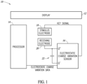
- FIG. 1 is a block diagram of a device 10 according to an embodiment.
- the device 10 may be any type of electronic device with a bendable display, such as a foldable or rollable mobile device, electronic reader, cellular phone, and tablet.
- the device 10 includes a display 12, a processor 14, an electrostatic charge variation sensor 16, a stimulus electrode 18, and a receiving electrode 20.
- the device 10 may include an equal number of stimulus and receiving electrodes.
- the display 12 is a bendable display that may be bent ( e.g., folded or rolled) onto itself. When the display 12 is in an open state, the display 12 is unbent ( e.g ., unfolded or unrolled). When the display 12 is in a closed state, the display 12 is bent ( e.g., folded or rolled) on to itself.
- the display 12 may be any type of flexible display, such as a light-emitting diode (LED) display, an organic light-emitting diode (OLED) display, and an electronic ink display.
- the processor 14 is electrically coupled to the electrostatic charge variation sensor 16.
- the processor 14 receives electrostatic charge variation data from the electrostatic charge variation sensor 16.
- the electrostatic charge variation data indicates measurements by the electrostatic charge variation sensor 16.
- the processor 14 decodes and validates the electrostatic charge variation data in order to determine whether the display 12 is in an open state or a closed state.
- the processor 14 may be any type of processor, controller, or microcontroller that is able to process data.
- the electrostatic charge variation sensor 16 is electrically coupled also to the stimulus electrode 18, and the receiving electrode 20.
- the electrostatic charge variation sensor 16 may be embedded in a multi-sensor device that includes a plurality of different sensors (e.g ., motion sensors, optical sensor, pressure sensors, etc.).
- the electrostatic charge variation sensor 16 measures variation of electrostatic charge (i.e., a change in electrostatic charge) on the receiving electrode 20. Measurement is made in a passive mode by a high impedance stage of the electrostatic charge variation sensor 16, without internal source of electric charges variation.
- the electrostatic charge variation sensor 16 provides the measured electrostatic charge variation as electrostatic charge variation data to the processor 14.
- the electrostatic charge variation sensor 16 includes a first input Q + (a positive terminal) and a second input Q - (a negative terminal).
- the electrostatic charge variation sensor 16 measures electrostatic charge variation on the receiving electrode 20 via the first input Q + and the second input Q-.
- the electrostatic charge variation sensor 16 measures electrostatic charge variation as a differential between signals received by the first input Q + and the second input Q-.
- an electrostatic charge variation measurement may not be based on a single data point. Rather, the electrostatic charge variation sensor 16 may have a sampling rate, for example, in the range of 200 hertz to 800 hertz, and determine an electrostatic charge variation measurement based on multiple measurements.
- a capacitor 22 may be electrically coupled between the first input Q + and the second input Q-. The capacitor 22 may receive and stores the electrostatic charge received by the receiving electrode 20. In this case, the electrostatic charge variation sensor 16 measures electrostatic charge stored in the capacitor 22.
- the electrostatic charge variation sensor 16 includes various electronic components (e.g., capacitors, resistors, amplifiers, etc.) to measure electrostatic charge variation.
- the electrostatic charge variation sensor 16 also generates and transmits a key signal to the stimulus electrode 18.
- the key signal is a signal that is encoded with a key.
- the processor 14 determines that the display 12 is in a closed state upon determining that the key signal has been received by the receiving electrode 20.
- the stimulus electrode 18 is made of a conductive material, such as copper.
- the stimulus electrode 18 receives the key signal from the electrostatic charge variation sensor 16, and transmits the key signal.
- the stimulus electrode 18 transmits the key signal repeatedly ( e.g ., every 300 to 400 milliseconds).
- the stimulus electrode 18 may pause transmission after every transmission of the key signal, for example for 100 to 200 milliseconds.
- the geometry of the stimulus electrode 18 determines the directivity of the electrode.
- the stimulus electrode 18 is square or rectangular in shape.
- the receiving electrode 20 is electrically coupled to the first input Q + and to the second input Q - of the electrostatic charge variation sensor 16 via the capacitor 22.
- the receiving electrode 20 is made of a conductive material, such as copper.
- the receiving electrode 20 receives an electrostatic charge variation in a surrounding environment.
- the electrostatic charge variation may be generated from a wide variety of sources, such as motion by a person, a presence of an alternating current (AC) power line, and the key signal being transmitted by the stimulus electrode 18.
- AC alternating current
- the receiving electrode 20 When the receiving electrode 20 is in proximity to the stimulus electrode 18 ( e.g ., within 1 to 15 millimeters of the stimulus electrode 18), the receiving electrode 20 receives the key signal transmitted by the stimulus electrode 18. As will be discussed in further detail below, the receiving electrode 20 receiving the key signal indicates that the display 12 is in a closed state.
- the geometry of the receiving electrode 20 determines the sensitivity of the electrode.
- the receiving electrode 20 is square or rectangular in shape.
- the stimulus electrode 18 and the receiving electrode 20 are positioned within a casing of the device 10 and directly underlie the display 12. Thereby, The a stimulus electrode 18, and the receiving electrode 20 are hidden.
- the electrostatic charge variation sensor 16 generates and transmits a key signal to the stimulus electrode 18, which in turn transmits the key signal repeatedly.
- the key signal may be generated by other components within the device 10 as well, as shone in Figure 2 disclosed herein.
- the device 10 in Figure 2 includes the display 12, the processor 14, the electrostatic charge variation sensor 16, the stimulus electrode 18, and the receiving electrode 20.
- the processor 14 generates and transmits the key signal to the stimulus electrode 18 instead of the electrostatic charge variation sensor 16.
- the processor 14 both generates and transmits the key signal, and decodes and validates the electrostatic charge variation data.
- the electrostatic charge variation sensor 16 does not need to be informed of the key used to generate the key signal.
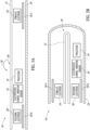
- Figure 3A shows the device 10 in an open state.
- Figure 3B shows the device 10 of Figure 3A in a closed state.
- Figures 3A and 3B show a case where the device 10 is a foldable device. It is beneficial to review Figures 3A and 3B together.
- the device 10 includes the display 12, the processor 14, the electrostatic charge variation sensor 16, the stimulus electrode 18, and the receiving electrode 20.
- the processor 14, the electrostatic charge variation sensor 16, the stimulus electrode 18, and the receiving electrode 20 are positioned within a casing or housing 24 of the device 10.
- the casing 24 encloses internal components of the device 10.
- the device 10 is configured to be folded at a portion 30 of the display 12.
- the stimulus electrode 18 is positioned on an opposite side of the portion 30 with respect to the processor 14, the electrostatic charge variation sensor 16, and the receiving electrode 20. Stated differently, the stimulus electrode 18 is positioned at a first end of the display 12, and the processor 14, the electrostatic charge variation sensor 16, and the receiving electrode 20 are positioned at a second end, opposite to the first end, of the display 12. Further, the processor 14, the electrostatic charge variation sensor 16, the stimulus electrode 18, and the receiving electrode 20 directly underlie the display 12. For example, the processor 14, the electrostatic charge variation sensor 16, the stimulus electrode 18, and the receiving electrode 20 are on a printed circuit board positioned on a surface of the casing 24 that faces the display 12.
- the device 10 also includes shields 26A, 26B.
- the shields 26A, 26B prevent or reduce noise in a surrounding environment from interfering with signals transmitted by the stimulus electrode 18 and signals received by the receiving electrode 20.
- the shields 26 may be grounded.
- shields 26A, 26B are respectively aligned with the stimulus electrode 18 and the receiving electrode 20, and are spaced from the display 12 by the stimulus electrode 18 and the receiving electrode 20, but the arrangement may be different.
- the display 12 in an open state, the display 12 is unfolded and is flat. A first end of the display 12 is spaced from a second end, opposite to the first end, of the display 12.
- the stimulus electrode 18 and the receiving electrode 20 do not face each other. The sides of the stimulus electrode 18 and the receiving electrode 20 that face the display 12 are facing the same direction. In the open state, the receiving electrode 20 is unable to receive and detect the key signal generated by the stimulus electrode 18.
- the display 12 may be folded in a direction 28 ( Figure 3A ).
- Figure 3B shows the display 12 in a closed state, folded onto itself.
- the first end is closer to the second end in the closed state than the in the open state.
- the display 12 is bent at the portion 30.
- the sides of the stimulus electrode 18 and the receiving electrode 20 that face the display 12 are facing each other, and the stimulus electrode 18 and the receiving electrode 20 are directly aligned with each other.
- the shield 26A behind the stimulus electrode 18 i.e., directly overlying the stimulus electrode 18 in Figure 3B
- the receiving electrode 20 i.e., directly underlying the receiving electrode 20 in Figure 3B
- the stimulus electrode 18 and the receiving electrode 20 are in close proximity to each other (e.g., within 1 to 15 millimeters of each other) such that the receiving electrode 20 is able to receive and detect the key signal transmitted by the stimulus electrode 18.
- Figure 4A is the device 10 in an open state according to another embodiment.
- Figure 4B shows the device 10 of Figure 4A in a closed state.
- Figures 4A and 4B show a case where the device 10 is a rollable device. It is beneficial to review Figures 4A and 4B together.
- the device 10 in Figures 4A and 4B include the display 12, the processor 14, the electrostatic charge variation sensor 16, the stimulus electrode 18, the receiving electrode 20, and shield 26A.
- the display 12 is a rollable display that is positioned between a first casing 32 and a second casing 34, and couples the first casing 32 and the second casing 34 to each other.
- the stimulus electrode 18 and a shield 26B are positioned within the first casing 32; and the processor 14, the electrostatic charge variation sensor 16, the receiving electrode 20, and the shield 26B are positioned in the second casing 34.
- the sides of the stimulus electrode 18 and the receiving electrode 20 that face the display 12 are facing each other.
- the display 12 in an open state, the display 12 is unrolled and is flat.
- the stimulus electrode 18 and the receiving electrode 20 are spaced from each other by the display 12.
- the stimulus electrode 18 and the receiving electrode 20 are spaced from each other by a sufficient distance such that the receiving electrode 20 is unable to receive and detect the key signal generated by the stimulus electrode 18.
- the display 12 in a closed state, is rolled on to itself in a direction 36.
- the first casing 32 and the second casing 34 are immediately adjacent to each other ( e.g ., physically contact each other), and the stimulus electrode 18 and the receiving electrode 20 are directly aligned with each other.
- the shield 26A adjacent to the stimulus electrode 18 i.e., within the first casing 32
- the shield 26B adjacent to the receiving electrode 20 i.e., within the second casing 34
- the stimulus electrode 18 and the receiving electrode 20 are in close proximity to each other ( e.g ., within 1 to 15 millimeters of each other) such that the receiving electrode 20 is able to receive and detect the key signal transmitted by the stimulus electrode 18.
- Figure 5 is a flow diagram of a possible method 38 for performing screen state. The method 38 is performed by the device 10.
- screen detection is initialized. For example, screen detection is performed periodically at fixed intervals. In an alternative, screen detection may be started in response to movement being detected by motion sensors (e.g ., accelerometer, gyroscope, etc.) of the device 10.
- motion sensors e.g ., accelerometer, gyroscope, etc.
- a key is selected.
- the key is a data word that includes a plurality of bits.
- the key may be 10110111.
- the key is selected by the electrostatic charge variation sensor 16.
- the key is selected by the processor 14.
- a key signal is generated and transmitted from the stimulus electrode 18.
- the key signal is a signal that is encoded with the key generated in block 40.
- the key signal is generated by the electrostatic charge variation sensor 16.
- the key signal is generated by the processor 14.
- the key signal is generated by interleaving zeroes into the key.
- the key of 10110111 is modified to 1000101000101010, and 1000101000101010 is encoded in the key signal.
- the key signal has twice as many bits as the key (e.g., an 8 bit key interleaved with zeroes will have 16 bits).
- Zeroes are interleaved into the key because the electrostatic charge variation sensor 16 measures electrostatic charge variation or change on the receiving electrode 20.
- the key signal should switch from a 0 bit to a 1 bit.
- Each bit of the key signal is transmitted from the stimulus electrode 18 serially. For example, a bit of the key signal may be transmitted every 15 to 25 milliseconds. Upon transmission of the entire key signal ( e.g., all the bits of 1000101000101010), transmission of the key signal is repeated. For example, the key signal may be transmitted every 300 to 400 milliseconds. The stimulus electrode 18 may pause transmission after every transmission of the key signal, for example for 100 to 200 milliseconds.
- Blocks 44, 46, 48, 50, 52 are performed concurrently with blocks 40 and 42.
- the processor 14 receives electrostatic charge variation data from the electrostatic charge variation sensor 16. Specifically, the receiving electrode 20 detects and receives electrostatic charges in a surrounding environment, the electrostatic charge variation sensor 16 measures electrostatic charge variations on the receiving electrode 20, and the processor 14 receives measurements of the electrostatic charge variations by the electrostatic charge variation sensor 16 as the electrostatic charge variation data.
- the electrostatic charge variation sensor 16 may measure electrostatic charge variation synchronously with transmission of a bit of the key signal by the stimulus electrode 18. For example, the stimulus electrode 18 transmits a bit of the key signal every 20 milliseconds, and the electrostatic charge variation sensor 16 outputs an electrostatic charge variation measurement every 20 milliseconds ( i.e., after every transmission of a bit).
- an electrostatic charge variation measurement may not be based on a single data point. Rather, the electrostatic charge variation sensor 16 may have a sampling rate, for example, in the range of 200 hertz to 800 hertz, and determine an electrostatic charge variation measurement based on multiple measurements. Thus, for a bit that is transmitted every 20 milliseconds, the electrostatic charge variation will make, for example, 4 to 16 measurements before outputting an electrostatic charge variation measurement.
- the processor 14 decodes electrostatic charge variation data received from the electrostatic charge variation sensor 16.
- the processor 14 decodes electrostatic charge variation data to extract a bit pattern of the electrostatic data. For example, the processor 14 determines a zero bit has been received by the receiving electrode 20 in a case where the electrostatic data indicates the electrostatic charge variation sensor 16 measured an electrostatic charge variation (e.g ., measured a voltage level of the electrostatic charge variation) below a threshold value, and determines a 1 bit has been received by the receiving electrode 20 in a case where the electrostatic data indicates the electrostatic charge variation sensor 16 measured an electrostatic charge variation ( e.g ., measured a voltage level of the electrostatic charge variation) equal to or greater than the threshold value.
- the processor 14 determines a zero bit has been received by the receiving electrode 20 in a case where the electrostatic data indicates the electrostatic charge variation sensor 16 measured an electrostatic charge variation ( e.g ., measured a voltage level of the electrostatic charge variation) below a threshold value, and determines a 1
- the processor 14 may collect electrostatic charge variation data over a period of time, and decode the electrostatic charge variation data after all of the bits of the key signal have been received. For example, in a case where the key signal has 16 bits, the processor 14 may collect 16 bits worth of electrostatic charge variation data, and decode the data after transmission of the last bit (the 16 th bit).
- the processor 14 determines whether the decoded electrostatic charge variation data matches the key used to generate the key signal in block 40. For example, the processor 14 determines whether the decoded electrostatic charge variation data has a bit pattern of 10110111.
- the receiving electrode 20 will receive the key signal transmitted by the stimulus electrode 18 in a closed state.
- the decoded electrostatic charge variation data will match the key in block 48.
- the method 38 moves to block 50 in which the processor 14 determines the device 10 is in a closed state.
- the receiving electrode 20 will not receive the key signal transmitted by the stimulus electrode 18 when the device 10 is in an open state.
- the decoded electrostatic charge variation data will not match the key in block 48.
- the method 38 moves to block 52 in which the processor 14 determines the device 10 is in an open state.
- the processor 14 is unable to determine whether the decoded electrostatic charge variation data matches the key in block 48.
- the electrostatic charge variation data may be unreadable because the electrostatic data is saturated or noisy due to, for example, a person touching the device. In this case, no decision may be made by the processor 14 in block 48, and the method 38 returns to block 44 in which additional electrostatic charge variation data is received by the processor 14.
- the display status (open state or closed state) of the device 10 does not change.
- the determined state may be outputted for further processing. For example, a power state of the device 10 may be adjusted based on whether the device 10 is in the closed state or the open state.
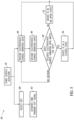
- Figure 6 is a flow diagram of a method 54 for performing screen state detection according to another solution.
- the method 54 determines whether the device 10 is in a closed state or an open state based on a number of valid signals and a number of invalid signals received by the receiving electrode 20.
- an N bit key is generated.
- the key is a data word that includes a plurality of bits.
- the key may be 10110111.
- the key is generated by the electrostatic charge variation sensor 16.
- the key is generated by the processor 14.
- a 2N bit key signal is generated and transmitted from the stimulus electrode 18.
- the key signal is generated by the electrostatic charge variation sensor 16.
- the key signal is generated by the processor 14.
- the key signal may be generated by interleaving zeroes into the key.
- the key of 10110111 is modified to 1000101000101010, and 1000101000101010 is encoded in the key signal.
- the key signal includes 2N bits, which is twice as many bits as the N bit key generated in block 56.
- each bit of the key signal is transmitted from the stimulus electrode 18 serially.
- a bit of the key signal may be transmitted every 15 to 25 milliseconds.
- transmission of the key signal is repeated.
- the key signal may be transmitted every 300 to 400 milliseconds.
- the receiving electrode 20 detects and receives electrostatic charge in a surrounding environment, and the electrostatic charge variation sensor 16 measures electrostatic charge variation received on the receiving electrode 20.
- the processor 14 determines whether a transmission count is equal to 2N, which is the number of bits included in the key signal.
- the transmission count indicates a total number of potential or candidate bits of the key signal that have been currently transmitted by the stimulus electrode 18.
- the transmission count is initialized at zero (i.e., the transmission count is zero when the method 54 is started at block 56), and is incremented in block 78, which will be discussed in further detail below.
- the method 54 moves to block 64.
- the processor 14 receives electrostatic charge variation data from the electrostatic charge variation sensor 16.
- the electrostatic charge variation data indicates the measurement of the electrostatic charge variation in block 60. Stated differently, the electrostatic charge variation is a measurement of a potential bit of the key signal.
- the processor 14 determines whether the electrostatic charge variation data is saturated. If the electrostatic charge variation data is saturated, the electrostatic charge variation on the receiving electrode 20 is outside of a readable range of the electrostatic charge variation sensor 16. Saturation of the electrostatic data may be caused by, for example, a person touching the receiving electrode 20.
- the processor 14 determines the electrostatic charge variation data is saturated in a case where the electrostatic charge variation data indicates the electrostatic charge variation sensor 16 measured an electrostatic charge variation (e.g ., measured a voltage level of the electrostatic charge variation) in block 60 that is greater than a threshold value for a determined period of time.
- the processor 14 may determine the electrostatic charge variation data as unsaturated in a case where the electrostatic charge variation data indicates the electrostatic charge variation sensor 16 measured an electrostatic charge variation ( e.g ., measured a voltage level of the electrostatic charge variation) in block 60 that is not greater than the threshold value for the determined period of time.
- the method 54 moves to block 70.
- the processor 14 determines that reception by the receiving electrode 20 is saturated. Consequently, the display status (open state or closed state) of the device 10 does not change.
- the method 54 then moves to block 84.
- the transmission count is reset to zero, along with a valid signal count and an invalid signal count.
- the valid signal count and the invalid signal count will be discussed in further detail below with respect to blocks 74 and 76, respectively.
- the processor 14 restarts checking reception of the key signal at a first, initial bit.
- the method 54 then returns to block 60 where the receiving electrode 20 detects and receives another electrostatic charge variation in a surrounding environment, and the electrostatic charge variation sensor 16 measures the electrostatic charge variation on the receiving electrode 20.
- the method 54 moves to block 72.
- the processor 14 determines whether the electrostatic charge variation data is valid or invalid.
- the processor 14 determines the electrostatic charge variation data is valid in a case where the electrostatic charge variation data indicates the (1) the electrostatic charge variation sensor 16 measured an electrostatic charge variation (e.g ., measured a voltage level of the electrostatic charge) in block 60 that is greater than a threshold value, and (2) the receiving electrode 20 received the electrostatic charge variation in block 60 in a determined time slot (e.g., a time slot in which the stimulus electrode 18 transmits a bit of the key signal).
- a determined time slot e.g., a time slot in which the stimulus electrode 18 transmits a bit of the key signal.
- the processor 14 may determine the electrostatic charge variation data is invalid in a case where the electrostatic charge variation data indicates the (1) the electrostatic charge variation sensor 16 measured an electrostatic charge variation (e.g ., measured a voltage level of the electrostatic charge variation in block 58) in block 60 that is not greater than the threshold value, or (2) the receiving electrode 20 received the electrostatic charge variation in block 60 outside of the determined time slot.
- the electrostatic charge variation data indicates the (1) the electrostatic charge variation sensor 16 measured an electrostatic charge variation (e.g ., measured a voltage level of the electrostatic charge variation in block 58) in block 60 that is not greater than the threshold value, or (2) the receiving electrode 20 received the electrostatic charge variation in block 60 outside of the determined time slot.
- the threshold value in block 72 may be less than the threshold value used in block 68.
- the method 54 moves to block 74.
- a valid signal count is incremented.
- the valid signal count indicates a total number of valid electrostatic data that has been generated by the electrostatic charge variation sensor 16.
- the valid signal count is initialized at zero (i.e., the valid signal count is zero when the method 54 is started at block 56). The method 54 then moves to block 78.
- the transmission count which was discussed with respect to block 62, is incremented.
- the method 54 then moves back to block 60 to detect and receive another electrostatic charge variation in the surrounding environment.
- the method 54 moves to block 76.
- an invalid signal count is incremented.
- the invalid signal count indicates a total number of invalid electrostatic data that has been generated by the electrostatic charge variation sensor 16.
- the invalid signal count is initialized at zero (i.e., the invalid signal count is zero when the method 54 is started at block 56). The method 54 then moves to block 78.
- the transmission count is incremented.
- the method 54 then moves back to block 60 to detect and receive another electrostatic charge variation in the surrounding environment.
- the method moves to block 80.
- the transmission count is 2N the receiving electrode 20 has possibly received all of the 2N bits of the key signal.
- the processor 14 determines whether the invalid signal count is less than an invalid signal threshold.
- the method 54 moves to block 82.
- the processor 14 determines the reception signal received by the receiving electrode 20 is too noisy. Consequently, the display status (open state or closed state) of the device 10 does not change. The method 54 then moves to block 84.
- the transmission count, the valid signal count, and the invalid signal count are reset to zero.
- the processor 14 restarts checking reception of the key signal at a first, initial bit. The method 54 then moves back to block 60 to detect and receive another electrostatic charge variation in the surrounding environment.
- the method 54 moves to block 86.
- the processor 14 determines whether the valid signal count is greater than a valid signal threshold.
- the method 54 moves to block 88.
- the processor 14 determines that the device 10 is in an open state as discussed above.
- the method 54 then moves to block 84, where the transmission count, the valid signal count, and the invalid signal count are reset to zero.
- the method 54 moves to block 90.
- the processor 14 determines that the device 10 is in a closed state as discussed above.
- the method 54 then moves to block 84, where the transmission count, the valid signal count, and the invalid signal count are reset to zero.
- the device 10 includes a stimulus electrode 18 and a corresponding receiving electrode 20.
- the device 10 may include any number of stimulus and receiving electrodes.
- Figure 7A shows the device 10 in an open state according to another embodiment disclosed herein.
- Figure 7B shows the device 10 of Figure 7A in a closed state.
- the device 10 shown in Figures 7A and 7B is the same as the device 10 shown in Figures 3A and 3B , except that the device 10 of Figures 7A, 7B includes two stimulus electrodes 18 adjacent to each other, and two receiving electrodes 20 adjacent to each other.
- each of the stimulus electrodes 18 are aligned with a respective receiving electrode 20.
- the stimulus electrodes 18 concurrently transmit key signals, and the receiving electrodes 20 concurrently receive electrostatic charge.
- Including two stimulus electrodes 18 and two receiving electrodes 20 as shown in Figures 7A and 7B allows a differential configuration for both reception and transmission.
- a first key signal e.g., 10100011
- a second key signal that is complementary to the first key signal e.g ., 01011100
- a second stimulus electrode e.g ., rightmost stimulus electrode in Figure 7B
- a first receiving electrode receives the first key signal from the first stimulus electrode
- a second receiving electrode receives the second key signal from the second stimulus electrode.
- the first receiving electrode is electrically coupled to the first input Q + (the positive terminal) of the electrostatic charge variation sensor 16
- the second receiving electrode 12B is electrically coupled to the second input Q - (the negative terminal) of the electrostatic charge variation sensor 16.
- the electrostatic charge variation sensor 16 measures electrostatic charge variation as a differential between signals received by the first input Q + and the second input Q-.
- the electrostatic charge variation sensor 16 measures the difference between the first input Q + and the second input Q-, noise, which is common to both inputs, will be canceled or at least strongly attenuated. Further, as the first and key signals are complementary and opposite in phase at the first input Q + and the second input Q - , the data signal will be doubled. As a result, the signal to noise ratio of the device 10 is greatly improved.
- the various embodiments disclosed herein provide devices and methods for performing screen state detection.
- the screen state detection may be used in conjunction with any device having a bendable display.
- the device and method utilizes an electrostatic charge variation sensor to detect whether the display is in an open state or a closed state.
- Example 1 A device, comprising:
- Example 2 The device of Example 1 wherein the processor is configured to generate the first key signal, and provide the first key signal to the first stimulus electrode for transmission.
- Example 3 The device of Example 1 wherein the electrostatic charge variation sensor is configured to generate the first key signal, and provide the first key signal to the first stimulus electrode for transmission.
- Example 4 The device of Example 1 wherein the bendable display includes a first end and a second end opposite to the first end, the first end is spaced from the second end in the open state, and the first end is closer to the second end in the closed state than in the open state.
- Example 5 The device of Example 1 wherein the bendable display is a foldable display that is in an unfolded state in the open state and in a folded state in the closed state.
- Example 6 The device of Example 1 wherein the bendable display is a rollable display that is in an unrolled state in the open state and in a rolled state in the closed state.
- Example 7 The device of Example 1, further comprising:
- Example 8 The device of Example 1 wherein the processor is configured to determine the bendable display is in the open state in a case where the electrostatic charge variation data does not match a key included in the first key signal, and determine the bendable display is in the closed state in a case where the electrostatic charge variation data matches a key included in the first key signal.
- Example 9 The device of Example 1 wherein
- Example 10 The device of Example 1 wherein
- Example 11 The device of Example 1 wherein first key signal is a key with zeroes inserted between key bits.
- Example 12 The device of Example 1, further comprising:
- Example 13 A method, comprising:
- Example 14 The method of Example 13 wherein the generating of the key signal is performed by the electrostatic charge variation sensor.
- Example 15 The method of Example 13 wherein the generating of the key signal is performed by the processor.
- Example 16 The method of Example 13 wherein the generating of the key includes inserting zeroes between bits of the key.
- Example 17 A method, comprising:
- Example 18 The method of Example 17, further comprising: filtering, by the processor, the electrostatic charge variation data to remove signals within a range of frequencies.
- Example 19 The method of Example 17, further comprising: determining, by the processor, whether or not the electrostatic charge variation data is saturated, the determining of the first number and the second number being performed in a case where the processor determines the electrostatic charge variation data is unsaturated.
- Example 20 The method of Example 17 wherein
Landscapes
- Engineering & Computer Science (AREA)
- Theoretical Computer Science (AREA)
- Computer Hardware Design (AREA)
- Physics & Mathematics (AREA)
- General Physics & Mathematics (AREA)
- Human Computer Interaction (AREA)
- General Engineering & Computer Science (AREA)
- Mathematical Physics (AREA)
- Signal Processing (AREA)
- Electronic Switches (AREA)
- Transmission And Conversion Of Sensor Element Output (AREA)
Abstract
Description
- The present invention is directed to screen state detection for electronic devices.
- Display technology has significantly improved. Today, displays, such as organic light-emitting diode (OLED) displays, are bendable and may be folded or rolled onto itself. Many portable electronic device have incorporated these displays to create foldable or rollable devices. For example, many smartphones and tablets include foldable displays to open and close similar to a book.
- Foldable and rollable devices typically include screen state detection in order to detect whether the device is open with the display being unfolded or unrolled, or closed with the display being folded or rolled. The device may, for example, turn the display on or off depending on whether the device is open or closed.
- Various techniques may be used to perform screen state detection. For example, capacitive sensing, switch mechanisms, and magnetic and optical solutions are common techniques to perform screen state detection. These solutions, however, involve complex algorithms, have high power consumptions, and often suffer from noise in a surrounding environment.
- Therefore, it is an aim to overcome the drawbacks of the prior art.
- According to the invention, a device and a method for performing screen state detection for a bendable display are provided, as defined in the attached claims.
- The screen state detection may be used in conjunction with, for example, foldable and rollable display devices. The device includes a stimulus electrode that transmits a key signal, a receiving electrode that detects electrostatic charge variation, and an electrostatic charge variation sensor that measures the variation of electrostatic charge received by the receiving electrode. The device decodes the sequence of the measured electrostatic charge variation to determine whether the key signal has been received by the receiving electrode. The device determines the bendable display is in a closed state (e.g., folded or rolled) when the key signal has been received by the receiving electrode.
- In the drawings, identical reference numbers identify similar features or elements. The size and relative positions of features in the drawings are not necessarily drawn to scale.
-
Figure 1 is a block diagram of a device for performing screen state detection, according to an embodiment disclosed herein. -
Figure 2 is a block diagram of the device according to another embodiment disclosed herein. -
Figure 3A shows the present device in an open state . -
Figure 3B shows the device ofFigure 3A in a closed state . -
Figure 4A shows the present device in an open state according to another embodiment. -
Figure 4B shows the device ofFigure 4A in a closed state. -
Figure 5 is a flow diagram of a method for performing screen state detection according to an embodiment. -
Figure 6 is a flow diagram of the present method for performing screen state detection according to another embodiment. -
Figure 7A is the present device in an open state according to another embodiment. -
Figure 7B is the device ofFigure 7A in a closed state. - Hereinafter, a device and method that performs screen state detection for a bendable display are described. The device and method utilize an electrostatic charge variation sensor to detect whether the display is in an open state or a closed state. The electrostatic charge variation sensor provides a low cost and low power solution for screen state detection.
-
Figure 1 is a block diagram of adevice 10 according to an embodiment. Thedevice 10 may be any type of electronic device with a bendable display, such as a foldable or rollable mobile device, electronic reader, cellular phone, and tablet. Thedevice 10 includes adisplay 12, aprocessor 14, an electrostaticcharge variation sensor 16, astimulus electrode 18, and a receivingelectrode 20. Thedevice 10 may include an equal number of stimulus and receiving electrodes. - The
display 12 is a bendable display that may be bent (e.g., folded or rolled) onto itself. When thedisplay 12 is in an open state, thedisplay 12 is unbent (e.g., unfolded or unrolled). When thedisplay 12 is in a closed state, thedisplay 12 is bent (e.g., folded or rolled) on to itself. Thedisplay 12 may be any type of flexible display, such as a light-emitting diode (LED) display, an organic light-emitting diode (OLED) display, and an electronic ink display. - The
processor 14 is electrically coupled to the electrostaticcharge variation sensor 16. Theprocessor 14 receives electrostatic charge variation data from the electrostaticcharge variation sensor 16. The electrostatic charge variation data indicates measurements by the electrostaticcharge variation sensor 16. As will be discussed in further detail below, theprocessor 14 decodes and validates the electrostatic charge variation data in order to determine whether thedisplay 12 is in an open state or a closed state. Theprocessor 14 may be any type of processor, controller, or microcontroller that is able to process data. - The electrostatic
charge variation sensor 16 is electrically coupled also to thestimulus electrode 18, and thereceiving electrode 20. The electrostaticcharge variation sensor 16 may be embedded in a multi-sensor device that includes a plurality of different sensors (e.g., motion sensors, optical sensor, pressure sensors, etc.). The electrostaticcharge variation sensor 16 measures variation of electrostatic charge (i.e., a change in electrostatic charge) on thereceiving electrode 20. Measurement is made in a passive mode by a high impedance stage of the electrostaticcharge variation sensor 16, without internal source of electric charges variation. The electrostaticcharge variation sensor 16 provides the measured electrostatic charge variation as electrostatic charge variation data to theprocessor 14. - The electrostatic
charge variation sensor 16 includes a first input Q+ (a positive terminal) and a second input Q- (a negative terminal). The electrostaticcharge variation sensor 16 measures electrostatic charge variation on thereceiving electrode 20 via the first input Q+ and the second input Q-. For example, the electrostaticcharge variation sensor 16 measures electrostatic charge variation as a differential between signals received by the first input Q+ and the second input Q-. It is noted that an electrostatic charge variation measurement may not be based on a single data point. Rather, the electrostaticcharge variation sensor 16 may have a sampling rate, for example, in the range of 200 hertz to 800 hertz, and determine an electrostatic charge variation measurement based on multiple measurements. For example, acapacitor 22 may be electrically coupled between the first input Q+ and the second input Q-. Thecapacitor 22 may receive and stores the electrostatic charge received by thereceiving electrode 20. In this case, the electrostaticcharge variation sensor 16 measures electrostatic charge stored in thecapacitor 22. - The electrostatic
charge variation sensor 16 includes various electronic components (e.g., capacitors, resistors, amplifiers, etc.) to measure electrostatic charge variation. The electrostaticcharge variation sensor 16, for example, includes an analog-to-digital converter to convert the measured electrostatic charge variation signal to a digital value, and output electrostatic charge variation data as a digital value. - The electrostatic
charge variation sensor 16 also generates and transmits a key signal to thestimulus electrode 18. As will be discussed in further detail below, the key signal is a signal that is encoded with a key. Theprocessor 14 determines that thedisplay 12 is in a closed state upon determining that the key signal has been received by the receivingelectrode 20. - The
stimulus electrode 18 is made of a conductive material, such as copper. Thestimulus electrode 18 receives the key signal from the electrostaticcharge variation sensor 16, and transmits the key signal. Thestimulus electrode 18 transmits the key signal repeatedly (e.g., every 300 to 400 milliseconds). Thestimulus electrode 18 may pause transmission after every transmission of the key signal, for example for 100 to 200 milliseconds. - The geometry of the
stimulus electrode 18 determines the directivity of the electrode. For example, thestimulus electrode 18 is square or rectangular in shape. - The receiving
electrode 20 is electrically coupled to the first input Q+ and to the second input Q- of the electrostaticcharge variation sensor 16 via thecapacitor 22. The receivingelectrode 20 is made of a conductive material, such as copper. The receivingelectrode 20 receives an electrostatic charge variation in a surrounding environment. The electrostatic charge variation may be generated from a wide variety of sources, such as motion by a person, a presence of an alternating current (AC) power line, and the key signal being transmitted by thestimulus electrode 18. - When the receiving
electrode 20 is in proximity to the stimulus electrode 18 (e.g., within 1 to 15 millimeters of the stimulus electrode 18), the receivingelectrode 20 receives the key signal transmitted by thestimulus electrode 18. As will be discussed in further detail below, the receivingelectrode 20 receiving the key signal indicates that thedisplay 12 is in a closed state. - The geometry of the receiving
electrode 20 determines the sensitivity of the electrode. For example, the receivingelectrode 20 is square or rectangular in shape. - As will be discussed in further detail below, the
stimulus electrode 18 and the receivingelectrode 20 are positioned within a casing of thedevice 10 and directly underlie thedisplay 12. Thereby, The astimulus electrode 18, and the receivingelectrode 20 are hidden. - In
Figure 1 , the electrostaticcharge variation sensor 16 generates and transmits a key signal to thestimulus electrode 18, which in turn transmits the key signal repeatedly. However, the key signal may be generated by other components within thedevice 10 as well, as shone inFigure 2 disclosed herein. - Similar to the device shown in
Figure 1 , thedevice 10 inFigure 2 includes thedisplay 12, theprocessor 14, the electrostaticcharge variation sensor 16, thestimulus electrode 18, and the receivingelectrode 20. However, in contrast toFigure 1 , theprocessor 14 generates and transmits the key signal to thestimulus electrode 18 instead of the electrostaticcharge variation sensor 16. As such, theprocessor 14 both generates and transmits the key signal, and decodes and validates the electrostatic charge variation data. Here, the electrostaticcharge variation sensor 16 does not need to be informed of the key used to generate the key signal. -
Figure 3A shows thedevice 10 in an open state.Figure 3B shows thedevice 10 ofFigure 3A in a closed state.Figures 3A and 3B show a case where thedevice 10 is a foldable device. It is beneficial to reviewFigures 3A and 3B together. - As discussed above, the
device 10 includes thedisplay 12, theprocessor 14, the electrostaticcharge variation sensor 16, thestimulus electrode 18, and the receivingelectrode 20. Theprocessor 14, the electrostaticcharge variation sensor 16, thestimulus electrode 18, and the receivingelectrode 20 are positioned within a casing orhousing 24 of thedevice 10. Thecasing 24 encloses internal components of thedevice 10. - In particular, here, the
device 10 is configured to be folded at aportion 30 of thedisplay 12. - The
stimulus electrode 18 is positioned on an opposite side of theportion 30 with respect to theprocessor 14, the electrostaticcharge variation sensor 16, and the receivingelectrode 20. Stated differently, thestimulus electrode 18 is positioned at a first end of thedisplay 12, and theprocessor 14, the electrostaticcharge variation sensor 16, and the receivingelectrode 20 are positioned at a second end, opposite to the first end, of thedisplay 12. Further, theprocessor 14, the electrostaticcharge variation sensor 16, thestimulus electrode 18, and the receivingelectrode 20 directly underlie thedisplay 12. For example, theprocessor 14, the electrostaticcharge variation sensor 16, thestimulus electrode 18, and the receivingelectrode 20 are on a printed circuit board positioned on a surface of thecasing 24 that faces thedisplay 12. - The
device 10 also includesshields shields stimulus electrode 18 and signals received by the receivingelectrode 20. Theshields 26 may be grounded. InFigures 3A and 3B , shields 26A, 26B are respectively aligned with thestimulus electrode 18 and the receivingelectrode 20, and are spaced from thedisplay 12 by thestimulus electrode 18 and the receivingelectrode 20, but the arrangement may be different. - As shown in
Figure 3A , in an open state, thedisplay 12 is unfolded and is flat. A first end of thedisplay 12 is spaced from a second end, opposite to the first end, of thedisplay 12. Thestimulus electrode 18 and the receivingelectrode 20 do not face each other. The sides of thestimulus electrode 18 and the receivingelectrode 20 that face thedisplay 12 are facing the same direction. In the open state, the receivingelectrode 20 is unable to receive and detect the key signal generated by thestimulus electrode 18. - The
display 12 may be folded in a direction 28 (Figure 3A ). -
Figure 3B shows thedisplay 12 in a closed state, folded onto itself. The first end is closer to the second end in the closed state than the in the open state. Thedisplay 12 is bent at theportion 30. The sides of thestimulus electrode 18 and the receivingelectrode 20 that face thedisplay 12 are facing each other, and thestimulus electrode 18 and the receivingelectrode 20 are directly aligned with each other. Further, theshield 26A behind the stimulus electrode 18 (i.e., directly overlying thestimulus electrode 18 inFigure 3B ) is spaced from theshield 26B behind the receiving electrode 20 (i.e., directly underlying the receivingelectrode 20 inFigure 3B ) by thestimulus electrode 18 and the receivingelectrode 20. In the closed state, thestimulus electrode 18 and the receivingelectrode 20 are in close proximity to each other (e.g., within 1 to 15 millimeters of each other) such that the receivingelectrode 20 is able to receive and detect the key signal transmitted by thestimulus electrode 18. -
Figure 4A is thedevice 10 in an open state according to another embodiment.Figure 4B shows thedevice 10 ofFigure 4A in a closed state.Figures 4A and 4B show a case where thedevice 10 is a rollable device. It is beneficial to reviewFigures 4A and 4B together. - Similar to the embodiment shown in
Figures 3A and 3B , thedevice 10 inFigures 4A and 4B include thedisplay 12, theprocessor 14, the electrostaticcharge variation sensor 16, thestimulus electrode 18, the receivingelectrode 20, and shield 26A. However, in contrast to the embodiment shown inFigures 3A and 3B , thedisplay 12 is a rollable display that is positioned between afirst casing 32 and asecond casing 34, and couples thefirst casing 32 and thesecond casing 34 to each other. Thestimulus electrode 18 and ashield 26B are positioned within thefirst casing 32; and theprocessor 14, the electrostaticcharge variation sensor 16, the receivingelectrode 20, and theshield 26B are positioned in thesecond casing 34. The sides of thestimulus electrode 18 and the receivingelectrode 20 that face thedisplay 12 are facing each other. - As shown in
Figure 4A , in an open state, thedisplay 12 is unrolled and is flat. Thestimulus electrode 18 and the receivingelectrode 20 are spaced from each other by thedisplay 12. Thestimulus electrode 18 and the receivingelectrode 20 are spaced from each other by a sufficient distance such that the receivingelectrode 20 is unable to receive and detect the key signal generated by thestimulus electrode 18. - As shown in
Figure 4B , in a closed state, thedisplay 12 is rolled on to itself in adirection 36. Thefirst casing 32 and thesecond casing 34 are immediately adjacent to each other (e.g., physically contact each other), and thestimulus electrode 18 and the receivingelectrode 20 are directly aligned with each other. Further, theshield 26A adjacent to the stimulus electrode 18 (i.e., within the first casing 32) is spaced from theshield 26B adjacent to the receiving electrode 20 (i.e., within the second casing 34) by thestimulus electrode 18 and the receivingelectrode 20. Thestimulus electrode 18 and the receivingelectrode 20 are in close proximity to each other (e.g., within 1 to 15 millimeters of each other) such that the receivingelectrode 20 is able to receive and detect the key signal transmitted by thestimulus electrode 18. -
Figure 5 is a flow diagram of apossible method 38 for performing screen state. Themethod 38 is performed by thedevice 10. - In
block 39, screen detection is initialized. For example, screen detection is performed periodically at fixed intervals. In an alternative, screen detection may be started in response to movement being detected by motion sensors (e.g., accelerometer, gyroscope, etc.) of thedevice 10. - In
block 40, a key is selected. The key is a data word that includes a plurality of bits. For example, the key may be 10110111. In thedevice 10 shown inFigure 1 , the key is selected by the electrostaticcharge variation sensor 16. In thedevice 10 shown inFigure 2 , the key is selected by theprocessor 14. - In
block 42, a key signal is generated and transmitted from thestimulus electrode 18. The key signal is a signal that is encoded with the key generated inblock 40. In thedevice 10 shown inFigure 1 , the key signal is generated by the electrostaticcharge variation sensor 16. In thedevice 10 shown inFigure 2 , the key signal is generated by theprocessor 14. - The key signal is generated by interleaving zeroes into the key. For example, the key of 10110111 is modified to 1000101000101010, and 1000101000101010 is encoded in the key signal. As a result, the key signal has twice as many bits as the key (e.g., an 8 bit key interleaved with zeroes will have 16 bits). Zeroes are interleaved into the key because the electrostatic
charge variation sensor 16 measures electrostatic charge variation or change on the receivingelectrode 20. As such, in order for 1 bit to be detected properly by the electrostaticcharge variation sensor 16, the key signal should switch from a 0 bit to a 1 bit. - Each bit of the key signal is transmitted from the
stimulus electrode 18 serially. For example, a bit of the key signal may be transmitted every 15 to 25 milliseconds. Upon transmission of the entire key signal (e.g., all the bits of 1000101000101010), transmission of the key signal is repeated. For example, the key signal may be transmitted every 300 to 400 milliseconds. Thestimulus electrode 18 may pause transmission after every transmission of the key signal, for example for 100 to 200 milliseconds. -
Blocks blocks block 44, theprocessor 14 receives electrostatic charge variation data from the electrostaticcharge variation sensor 16. Specifically, the receivingelectrode 20 detects and receives electrostatic charges in a surrounding environment, the electrostaticcharge variation sensor 16 measures electrostatic charge variations on the receivingelectrode 20, and theprocessor 14 receives measurements of the electrostatic charge variations by the electrostaticcharge variation sensor 16 as the electrostatic charge variation data. - The electrostatic
charge variation sensor 16 may measure electrostatic charge variation synchronously with transmission of a bit of the key signal by thestimulus electrode 18. For example, thestimulus electrode 18 transmits a bit of the key signal every 20 milliseconds, and the electrostaticcharge variation sensor 16 outputs an electrostatic charge variation measurement every 20 milliseconds (i.e., after every transmission of a bit). - As noted above, an electrostatic charge variation measurement may not be based on a single data point. Rather, the electrostatic
charge variation sensor 16 may have a sampling rate, for example, in the range of 200 hertz to 800 hertz, and determine an electrostatic charge variation measurement based on multiple measurements. Thus, for a bit that is transmitted every 20 milliseconds, the electrostatic charge variation will make, for example, 4 to 16 measurements before outputting an electrostatic charge variation measurement. - In
block 46, theprocessor 14 decodes electrostatic charge variation data received from the electrostaticcharge variation sensor 16. Theprocessor 14 decodes electrostatic charge variation data to extract a bit pattern of the electrostatic data. For example, theprocessor 14 determines a zero bit has been received by the receivingelectrode 20 in a case where the electrostatic data indicates the electrostaticcharge variation sensor 16 measured an electrostatic charge variation (e.g., measured a voltage level of the electrostatic charge variation) below a threshold value, and determines a 1 bit has been received by the receivingelectrode 20 in a case where the electrostatic data indicates the electrostaticcharge variation sensor 16 measured an electrostatic charge variation (e.g., measured a voltage level of the electrostatic charge variation) equal to or greater than the threshold value. - The
processor 14 may collect electrostatic charge variation data over a period of time, and decode the electrostatic charge variation data after all of the bits of the key signal have been received. For example, in a case where the key signal has 16 bits, theprocessor 14 may collect 16 bits worth of electrostatic charge variation data, and decode the data after transmission of the last bit (the 16th bit). - In
block 48, theprocessor 14 determines whether the decoded electrostatic charge variation data matches the key used to generate the key signal inblock 40. For example, theprocessor 14 determines whether the decoded electrostatic charge variation data has a bit pattern of 10110111. - As discussed above with respect to
Figures 3B and4B , the receivingelectrode 20 will receive the key signal transmitted by thestimulus electrode 18 in a closed state. Thus, in a case where thedevice 10 is in a closed state, the decoded electrostatic charge variation data will match the key inblock 48. Accordingly, in a case where the decoded electrostatic charge variation data matches the key inblock 48, themethod 38 moves to block 50 in which theprocessor 14 determines thedevice 10 is in a closed state. - Conversely, as discussed above with respect to
Figures 3A and4A , the receivingelectrode 20 will not receive the key signal transmitted by thestimulus electrode 18 when thedevice 10 is in an open state. Thus, in a case where thedevice 10 is in an open state, the decoded electrostatic charge variation data will not match the key inblock 48. Accordingly, in a case where the decoded electrostatic charge variation data does not match the key inblock 48, themethod 38 moves to block 52 in which theprocessor 14 determines thedevice 10 is in an open state. - In some cases, the
processor 14 is unable to determine whether the decoded electrostatic charge variation data matches the key inblock 48. For example, the electrostatic charge variation data may be unreadable because the electrostatic data is saturated or noisy due to, for example, a person touching the device. In this case, no decision may be made by theprocessor 14 inblock 48, and themethod 38 returns to block 44 in which additional electrostatic charge variation data is received by theprocessor 14. The display status (open state or closed state) of thedevice 10 does not change. - Upon determining the closed state in
block 50 or the open state inblock 52, the determined state may be outputted for further processing. For example, a power state of thedevice 10 may be adjusted based on whether thedevice 10 is in the closed state or the open state. -
Figure 6 is a flow diagram of amethod 54 for performing screen state detection according to another solution. In contrast to themethod 38 shown inFigure 5 , themethod 54 determines whether thedevice 10 is in a closed state or an open state based on a number of valid signals and a number of invalid signals received by the receivingelectrode 20. - In
block 56, similar to block 40 inFigure 5 , an N bit key is generated. As discussed above, the key is a data word that includes a plurality of bits. For example, the key may be 10110111. InFigure 1 , the key is generated by the electrostaticcharge variation sensor 16. InFigure 2 , the key is generated by theprocessor 14. - In
block 58, similar to block 42 inFigure 5 , a 2N bit key signal is generated and transmitted from thestimulus electrode 18. In theFigure 1 , the key signal is generated by the electrostaticcharge variation sensor 16. InFigure 2 , the key signal is generated by theprocessor 14. - As discussed above, the key signal may be generated by interleaving zeroes into the key. For example, the key of 10110111 is modified to 1000101000101010, and 1000101000101010 is encoded in the key signal. As a result, the key signal includes 2N bits, which is twice as many bits as the N bit key generated in
block 56. - Further, as discussed above, each bit of the key signal is transmitted from the
stimulus electrode 18 serially. For example, a bit of the key signal may be transmitted every 15 to 25 milliseconds. Upon transmission of the entire key signal (e.g., all the bits of 1000101000101010), transmission of the key signal is repeated. For example, the key signal may be transmitted every 300 to 400 milliseconds. - In
block 60, the receivingelectrode 20 detects and receives electrostatic charge in a surrounding environment, and the electrostaticcharge variation sensor 16 measures electrostatic charge variation received on the receivingelectrode 20. - In
block 62, theprocessor 14 determines whether a transmission count is equal to 2N, which is the number of bits included in the key signal. The transmission count indicates a total number of potential or candidate bits of the key signal that have been currently transmitted by thestimulus electrode 18. The transmission count is initialized at zero (i.e., the transmission count is zero when themethod 54 is started at block 56), and is incremented inblock 78, which will be discussed in further detail below. - In a case where the transmission count is not equal to 2N, the
method 54 moves to block 64. Inblock 64, theprocessor 14 receives electrostatic charge variation data from the electrostaticcharge variation sensor 16. The electrostatic charge variation data indicates the measurement of the electrostatic charge variation inblock 60. Stated differently, the electrostatic charge variation is a measurement of a potential bit of the key signal. - In
block 66, theprocessor 14 filters the electrostatic charge variation data to remove certain frequencies from the electrostatic charge variation data (e.g., noise, electrostatic charge variation caused by unwanted sources, such as an AC power line, etc.). Theprocessor 14 may apply a low pass filter, a high pass filter, a band pass filter, or a combination thereof to the electrostatic charge variation data. - In
block 68, theprocessor 14 determines whether the electrostatic charge variation data is saturated. If the electrostatic charge variation data is saturated, the electrostatic charge variation on the receivingelectrode 20 is outside of a readable range of the electrostaticcharge variation sensor 16. Saturation of the electrostatic data may be caused by, for example, a person touching the receivingelectrode 20. - For example, the
processor 14 determines the electrostatic charge variation data is saturated in a case where the electrostatic charge variation data indicates the electrostaticcharge variation sensor 16 measured an electrostatic charge variation (e.g., measured a voltage level of the electrostatic charge variation) inblock 60 that is greater than a threshold value for a determined period of time. Theprocessor 14 may determine the electrostatic charge variation data as unsaturated in a case where the electrostatic charge variation data indicates the electrostaticcharge variation sensor 16 measured an electrostatic charge variation (e.g., measured a voltage level of the electrostatic charge variation) inblock 60 that is not greater than the threshold value for the determined period of time. - In a case where the electrostatic charge variation data is saturated, the
method 54 moves to block 70. Inblock 70, theprocessor 14 determines that reception by the receivingelectrode 20 is saturated. Consequently, the display status (open state or closed state) of thedevice 10 does not change. Themethod 54 then moves to block 84. - In
block 84, the transmission count is reset to zero, along with a valid signal count and an invalid signal count. The valid signal count and the invalid signal count will be discussed in further detail below with respect toblocks processor 14 restarts checking reception of the key signal at a first, initial bit. Themethod 54 then returns to block 60 where the receivingelectrode 20 detects and receives another electrostatic charge variation in a surrounding environment, and the electrostaticcharge variation sensor 16 measures the electrostatic charge variation on the receivingelectrode 20. - Returning to block 68, in a case where the electrostatic charge variation data is unsaturated, the
method 54 moves to block 72. Inblock 72, theprocessor 14 determines whether the electrostatic charge variation data is valid or invalid. - In one embodiment, the
processor 14 determines the electrostatic charge variation data is valid in a case where the electrostatic charge variation data indicates the (1) the electrostaticcharge variation sensor 16 measured an electrostatic charge variation (e.g., measured a voltage level of the electrostatic charge) inblock 60 that is greater than a threshold value, and (2) the receivingelectrode 20 received the electrostatic charge variation inblock 60 in a determined time slot (e.g., a time slot in which thestimulus electrode 18 transmits a bit of the key signal). - The
processor 14 may determine the electrostatic charge variation data is invalid in a case where the electrostatic charge variation data indicates the (1) the electrostaticcharge variation sensor 16 measured an electrostatic charge variation (e.g., measured a voltage level of the electrostatic charge variation in block 58) inblock 60 that is not greater than the threshold value, or (2) the receivingelectrode 20 received the electrostatic charge variation inblock 60 outside of the determined time slot. - The threshold value in
block 72 may be less than the threshold value used inblock 68. - In a case where the electrostatic charge variation data is valid, the
method 54 moves to block 74. Inblock 74, a valid signal count is incremented. The valid signal count indicates a total number of valid electrostatic data that has been generated by the electrostaticcharge variation sensor 16. The valid signal count is initialized at zero (i.e., the valid signal count is zero when themethod 54 is started at block 56). Themethod 54 then moves to block 78. - In
block 78, the transmission count, which was discussed with respect to block 62, is incremented. Themethod 54 then moves back to block 60 to detect and receive another electrostatic charge variation in the surrounding environment. - Returning to block 72, in a case where the electrostatic charge variation data is invalid, the
method 54 moves to block 76. Inblock 76, an invalid signal count is incremented. The invalid signal count indicates a total number of invalid electrostatic data that has been generated by the electrostaticcharge variation sensor 16. The invalid signal count is initialized at zero (i.e., the invalid signal count is zero when themethod 54 is started at block 56). Themethod 54 then moves to block 78. - As discussed above, in
block 78, the transmission count is incremented. Themethod 54 then moves back to block 60 to detect and receive another electrostatic charge variation in the surrounding environment. - Returning to block 62, in a case where the transmission count is equal to 2N, the method moves to block 80. When the transmission count is 2N the receiving
electrode 20 has possibly received all of the 2N bits of the key signal. Inblock 80, theprocessor 14 determines whether the invalid signal count is less than an invalid signal threshold. - In a case where the invalid signal count is not less than the invalid signal threshold, the
method 54 moves to block 82. Inblock 82, theprocessor 14 determines the reception signal received by the receivingelectrode 20 is too noisy. Consequently, the display status (open state or closed state) of thedevice 10 does not change. Themethod 54 then moves to block 84. - As discussed above, in
block 84, the transmission count, the valid signal count, and the invalid signal count are reset to zero. By resetting the transmission count, the valid signal count, and the invalid signal count to zero, theprocessor 14 restarts checking reception of the key signal at a first, initial bit. Themethod 54 then moves back to block 60 to detect and receive another electrostatic charge variation in the surrounding environment. - Returning to block 80, in a case where the invalid signal count is less than the invalid signal threshold, the
method 54 moves to block 86. Inblock 86, theprocessor 14 determines whether the valid signal count is greater than a valid signal threshold. - In a case where the valid signal count is not greater than the valid signal threshold, the
method 54 moves to block 88. Inblock 88, theprocessor 14 determines that thedevice 10 is in an open state as discussed above. Themethod 54 then moves to block 84, where the transmission count, the valid signal count, and the invalid signal count are reset to zero. - Returning to block 86, in a case where the valid signal count is greater than the valid signal threshold, the
method 54 moves to block 90. Inblock 90, theprocessor 14 determines that thedevice 10 is in a closed state as discussed above. Themethod 54 then moves to block 84, where the transmission count, the valid signal count, and the invalid signal count are reset to zero. - In the discussion above, the
device 10 includes astimulus electrode 18 and a corresponding receivingelectrode 20. However, thedevice 10 may include any number of stimulus and receiving electrodes. For example,Figure 7A shows thedevice 10 in an open state according to another embodiment disclosed herein.Figure 7B shows thedevice 10 ofFigure 7A in a closed state. Thedevice 10 shown inFigures 7A and 7B is the same as thedevice 10 shown inFigures 3A and 3B , except that thedevice 10 ofFigures 7A, 7B includes twostimulus electrodes 18 adjacent to each other, and two receivingelectrodes 20 adjacent to each other. In the closed state, each of thestimulus electrodes 18 are aligned with arespective receiving electrode 20. Thestimulus electrodes 18 concurrently transmit key signals, and the receivingelectrodes 20 concurrently receive electrostatic charge. - Including two
stimulus electrodes 18 and two receivingelectrodes 20 as shown inFigures 7A and 7B allows a differential configuration for both reception and transmission. Here, a first key signal (e.g., 10100011) is transmitted from a first stimulus electrode (e.g., leftmost stimulus electrode inFigure 7B ), and a second key signal that is complementary to the first key signal (e.g., 01011100) is transmitted from a second stimulus electrode (e.g., rightmost stimulus electrode inFigure 7B ). In the closed state as shown inFigure 7B , a first receiving electrode (e.g., leftmost receiving electrode inFigure 7B ) receives the first key signal from the first stimulus electrode, and a second receiving electrode (e.g., rightmost stimulus electrode inFigure 7B ) receives the second key signal from the second stimulus electrode. The first receiving electrode is electrically coupled to the first input Q+ (the positive terminal) of the electrostaticcharge variation sensor 16, and the second receiving electrode 12B is electrically coupled to the second input Q- (the negative terminal) of the electrostaticcharge variation sensor 16. As such, the electrostaticcharge variation sensor 16 measures electrostatic charge variation as a differential between signals received by the first input Q+ and the second input Q-. - As the electrostatic
charge variation sensor 16 measures the difference between the first input Q+ and the second input Q-, noise, which is common to both inputs, will be canceled or at least strongly attenuated. Further, as the first and key signals are complementary and opposite in phase at the first input Q+ and the second input Q-, the data signal will be doubled. As a result, the signal to noise ratio of thedevice 10 is greatly improved. - The various embodiments disclosed herein provide devices and methods for performing screen state detection. The screen state detection may be used in conjunction with any device having a bendable display. The device and method utilizes an electrostatic charge variation sensor to detect whether the display is in an open state or a closed state.
- Finally, it is clear that modifications and variations may be made to the device described and illustrated herein without departing from the scope of the present invention, as defined in the attached claims.
- For example, the various embodiments described above can be combined to provide further embodiments. Example embodiments of the present invention are summarized here.
- Example 1. A device, comprising:
- a bendable display;
- a first stimulus electrode configured to transmit a first key signal;
- a first receiving electrode configured to receive an electrostatic charge variation in a surrounding environment;
- an electrostatic charge variation sensor configured to measure the electrostatic charge variation, and generate electrostatic charge variation data based on the measured electrostatic charge variation; and
- a processor configured to determine whether the bendable display is in an open state or a closed state based on the electrostatic charge variation data and the first key signal.
- Example 2. The device of Example 1 wherein the processor is configured to generate the first key signal, and provide the first key signal to the first stimulus electrode for transmission.
- Example 3. The device of Example 1 wherein the electrostatic charge variation sensor is configured to generate the first key signal, and provide the first key signal to the first stimulus electrode for transmission.
- Example 4. The device of Example 1 wherein the bendable display includes a first end and a second end opposite to the first end, the first end is spaced from the second end in the open state, and the first end is closer to the second end in the closed state than in the open state.
- Example 5. The device of Example 1 wherein the bendable display is a foldable display that is in an unfolded state in the open state and in a folded state in the closed state.
- Example 6. The device of Example 1 wherein the bendable display is a rollable display that is in an unrolled state in the open state and in a rolled state in the closed state.
- Example 7. The device of Example 1, further comprising:
- a first shield, the first stimulus electrode being positioned between the bendable display and the first shield; and
- a second shield, the first receiving electrode being positioned between the bendable display and the second shield.
- Example 8. The device of Example 1 wherein the processor is configured to determine the bendable display is in the open state in a case where the electrostatic charge variation data does not match a key included in the first key signal, and determine the bendable display is in the closed state in a case where the electrostatic charge variation data matches a key included in the first key signal.
- Example 9. The device of Example 1 wherein
- the processor is configured to determine a number of times valid electrostatic charge variation data has been generated by the electrostatic charge variation sensor, and
- the processor is configured to determine the bendable display is in the open state in a case where the number of times is greater than a threshold value, and determines the bendable display is in the closed state in a case where the number of times is not greater than the threshold value.
- Example 10. The device of Example 1 wherein
- the processor is configured to determine a number of times invalid electrostatic charge variation data has been generated by the electrostatic charge variation sensor, and
- the processor is configured to determine the electrostatic charge variation is noise in a case where the number of times is not less than a threshold value.
- Example 11. The device of Example 1 wherein first key signal is a key with zeroes inserted between key bits.
- Example 12. The device of Example 1, further comprising:
- a second stimulus electrode positioned adjacent to the first stimulus electrode and configured to transmit a second key signal that is complementary to the first key signal; and
- a second receiving electrode positioned adjacent to the first receiving electrode and configured to receive the electrostatic charge variation.
- Example 13. A method, comprising:
- generating a key signal based on a key;
- transmitting, by a stimulus electrode, the key signal;
- receiving, by a receiving electrode, an electrostatic charge variation in a surrounding environment;
- measuring, by an electrostatic charge variation sensor, the electrostatic charge variation ;
- generating, by the electrostatic charge variation sensor, electrostatic charge variation data based on the measured electrostatic charge variation; and
- determining, by a processor, whether a bendable display is in an open state or a closed state based on the electrostatic charge variation data and the key signal.
- Example 14. The method of Example 13 wherein the generating of the key signal is performed by the electrostatic charge variation sensor.
- Example 15. The method of Example 13 wherein the generating of the key signal is performed by the processor.
- Example 16. The method of Example 13 wherein the generating of the key includes inserting zeroes between bits of the key.
- Example 17. A method, comprising:
- transmitting, by a stimulus electrode, a key signal;
- receiving, by a receiving electrode, an electrostatic charge variation in a surrounding environment;
- measuring, by an electrostatic charge variation sensor, the electrostatic charge variation;
- generating, by the electrostatic charge variation sensor, electrostatic charge variation data based on the measured electrostatic charge variation;
- determining, by a processor, a first number indicating a number of times valid electrostatic charge variation data has been generated by the electrostatic charge variation sensor;
- determining, by the processor, a second number indicating a number of times invalid electrostatic charge variation data has been generated by the electrostatic charge variation sensor; and
- determining, by the processor, whether a bendable display is in an open state or a closed state based on the first number and the second number.
- Example 18. The method of Example 17, further comprising:
filtering, by the processor, the electrostatic charge variation data to remove signals within a range of frequencies. - Example 19. The method of Example 17, further comprising:
determining, by the processor, whether or not the electrostatic charge variation data is saturated, the determining of the first number and the second number being performed in a case where the processor determines the electrostatic charge variation data is unsaturated. - Example 20. The method of Example 17 wherein
- the processor determines the electrostatic charge variation data is valid in a case where electrostatic charge variation data indicates (1) a voltage level of the measured electrostatic charge variation is greater than a threshold value, and (2) the receiving electrode received the electrostatic charge variation in a determined time slot, and
- the processor determines the electrostatic charge variation data is invalid in a case where electrostatic charge variation data indicates (1) the voltage level of the measured electrostatic charge variation is not greater than the threshold value, or (2) the receiving electrode did not receive the electrostatic charge variation in the determined time slot.
Claims (15)
- A device, comprising:a bendable display (12);a first stimulus electrode (18) configured to transmit a first key signal;a first receiving electrode (20) configured to receive an electrostatic charge variation in a surrounding environment;an electrostatic charge variation sensor (16) configured to measure the electrostatic charge variation, and generate electrostatic charge variation data based on the measured electrostatic charge variation; anda processor (14) configured to determine whether the bendable display is in an open state or a closed state based on the electrostatic charge variation data and the first key signal.
- The device of claim 1, wherein the processor (14) is configured to generate the first key signal, and provide the first key signal to the first stimulus electrode for transmission.
- The device of claim 1, wherein the electrostatic charge variation sensor (16) is configured to generate the first key signal, and provide the first key signal to the first stimulus electrode for transmission.
- The device of any of the preceding claims, wherein the bendable display (12) includes a first end and a second end opposite to the first end, the first end is spaced from the second end in the open state, and the first end is closer to the second end in the closed state than in the open state.
- The device of any of the preceding claims, wherein the bendable display (12) is a foldable display that is in an unfolded state in the open state and in a folded state in the closed state or is a rollable display that is in an unrolled state in the open state and in a rolled state in the closed state.
- The device of any of claims 1-4, further comprising:a first shield (24), the first stimulus electrode (18) being positioned between the bendable display and the first shield; anda second shield (34), the first receiving electrode (20) being positioned between the bendable display and the second shield.
- The device of any of the preceding claims, wherein the processor (14) is configured to determine the bendable display is in the open state in a case where the electrostatic charge variation data does not match a key included in the first key signal, and determine the bendable display is in the closed state in a case where the electrostatic charge variation data matches a key included in the first key signal.
- The device of any of the preceding claims, whereinthe processor (14) is configured to determine a number of times valid electrostatic charge variation data has been generated by the electrostatic charge variation sensor, andthe processor is configured to determine the bendable display is in the open state in a case where the number of times is greater than a threshold value, and determines the bendable display is in the closed state in a case where the number of times is not greater than the threshold value.
- The device of any of the preceding claims, whereinthe processor (14) is configured to determine a number of times invalid electrostatic charge variation data has been generated by the electrostatic charge variation sensor, andthe processor is configured to determine the electrostatic charge variation is noise in a case where the number of times is not less than a threshold value.
- The device of any of the preceding claims, further comprising:a second stimulus electrode (18) positioned adjacent to the first stimulus electrode (18) and configured to transmit a second key signal that is complementary to the first key signal; anda second receiving electrode (20) positioned adjacent to the first receiving electrode (20) and configured to receive the electrostatic charge variation.
- A method, comprising:generating a key signal based on a key;transmitting, by a stimulus electrode (18), the key signal;receiving, by a receiving electrode (20), an electrostatic charge variation in a surrounding environment;measuring, by an electrostatic charge variation sensor (16), the electrostatic charge variation ;generating, by the electrostatic charge variation sensor (16), electrostatic charge variation data based on the measured electrostatic charge variation; anddetermining, by a processor (14), whether a bendable display is in an open state or a closed state based on the electrostatic charge variation data and the key signal.
- The method of claim 13 wherein the generating of the key signal is performed by the electrostatic charge variation sensor or by the processor.
- The method of claim 11 or 12, wherein the generating of the key includes inserting zeroes between bits of the key.
- The method of any of claims 11-13, wherein determining whether a bendable display is in an open state or a closed state comprises determining, a first number indicating a number of times valid electrostatic charge variation data has been generated by the electrostatic charge variation sensor;determining a second number indicating a number of times invalid electrostatic charge variation data has been generated by the electrostatic charge variation sensor; anddetermining whether the bendable display is in an open state or a closed state based on the first number and the second number.
- The method of the preceding claim, further comprising:
filtering, by the processor (14), the electrostatic charge variation data to remove signals within a range of frequencies.
Applications Claiming Priority (1)
| Application Number | Priority Date | Filing Date | Title |
|---|---|---|---|
| US17/578,336 US11989065B2 (en) | 2022-01-18 | 2022-01-18 | Screen state detection using an electrostatic charge variation sensor |
Publications (2)
| Publication Number | Publication Date |
|---|---|
| EP4213471A1 true EP4213471A1 (en) | 2023-07-19 |
| EP4213471B1 EP4213471B1 (en) | 2025-06-04 |
Family
ID=84943626
Family Applications (1)
| Application Number | Title | Priority Date | Filing Date |
|---|---|---|---|
| EP23151090.0A Active EP4213471B1 (en) | 2022-01-18 | 2023-01-11 | Screen state detection using an electrostatic charge variation sensor |
Country Status (3)
| Country | Link |
|---|---|
| US (1) | US11989065B2 (en) |
| EP (1) | EP4213471B1 (en) |
| CN (1) | CN116469325B (en) |
Citations (5)
| Publication number | Priority date | Publication date | Assignee | Title |
|---|---|---|---|---|
| KR20080095447A (en) * | 2007-04-24 | 2008-10-29 | 에이디반도체(주) | Slide cell phone to determine whether it is opened or closed through the capacitive sensor |
| US20090086879A1 (en) * | 2007-09-26 | 2009-04-02 | Kabushiki Kaisha Toshiba | Sensor device, and sensor system and electronic device using the sensor device |
| US20110304564A1 (en) * | 2010-06-10 | 2011-12-15 | Kim Tae-Hwan | Liquid crystal display device associated with touch panel |
| US20120315847A1 (en) * | 2010-03-25 | 2012-12-13 | Silego Technology, Inc. | Capacitive coupling based proximity sensor |
| US20200033992A1 (en) * | 2017-10-02 | 2020-01-30 | Murata Manufacturing Co., Ltd. | Pressure sensor for use in folding structure, and electronic device |
Family Cites Families (27)
| Publication number | Priority date | Publication date | Assignee | Title |
|---|---|---|---|---|
| US20070100666A1 (en) | 2002-08-22 | 2007-05-03 | Stivoric John M | Devices and systems for contextual and physiological-based detection, monitoring, reporting, entertainment, and control of other devices |
| AU2006292891A1 (en) * | 2005-09-20 | 2007-03-29 | David Norris Kenwright | Apparatus and method for proximity-responsive display materials |
| KR101118984B1 (en) | 2009-12-02 | 2012-03-13 | 최용환 | Door opening -closing Method and Transmitting Apparatus for opening - closing Door using thereof |
| JP2011146915A (en) | 2010-01-14 | 2011-07-28 | Sony Corp | Information processing device, opening/closing angle detecting method, and opening/closing angle detecting program |
| CN102759949A (en) | 2011-04-28 | 2012-10-31 | 富泰华工业(深圳)有限公司 | Electronic device and state control method |
| WO2013084087A1 (en) * | 2011-12-08 | 2013-06-13 | Sony Mobile Communications Ab | System and method for identifying the shape of a display device |
| US9524030B2 (en) | 2013-04-26 | 2016-12-20 | Immersion Corporation | Haptic feedback for interactions with foldable-bendable displays |
| ES2534702B1 (en) | 2013-09-24 | 2016-02-09 | Ontech Security, Sl | ELECTROSTATIC FIELD SENSOR AND SECURITY SYSTEM IN INTERIOR SPACES |
| KR102511325B1 (en) * | 2014-04-18 | 2023-03-20 | 가부시키가이샤 한도오따이 에네루기 켄큐쇼 | Display device and operation method thereof |
| KR20160001602A (en) | 2014-06-26 | 2016-01-06 | 삼성전자주식회사 | Foldable electronic apparatus and method for performing interfacing thereof |
| CN104407675B (en) * | 2014-12-12 | 2017-07-28 | 京东方科技集团股份有限公司 | Display screen reel system and its control method |
| CN104700762A (en) * | 2015-04-07 | 2015-06-10 | 京东方科技集团股份有限公司 | Array substrate, display panel and bending degree detection method |
| KR20160136013A (en) | 2015-05-19 | 2016-11-29 | 엘지전자 주식회사 | Mobile terminal and method for controlling the same |
| CN105739637B (en) * | 2016-03-14 | 2018-12-28 | 京东方科技集团股份有限公司 | Key board unit |
| US10191147B2 (en) | 2016-08-05 | 2019-01-29 | Microsoft Technology Licensing, Llc | Ultrasound based configuration detection of a multipart electronic apparatus |
| KR102496467B1 (en) * | 2016-11-23 | 2023-02-06 | 엘지디스플레이 주식회사 | Flexible display device |
| US20190064950A1 (en) | 2017-08-24 | 2019-02-28 | Int Tech Co., Ltd. | Foldable electronic device and control method thereof |
| KR20190100795A (en) | 2018-02-21 | 2019-08-29 | 삼성전자주식회사 | Flexible electronic device including light sensor and operation method thereof |
| CN109584725B (en) * | 2019-01-02 | 2021-10-01 | 上海天马有机发光显示技术有限公司 | A display panel and display device |
| US10712862B1 (en) * | 2019-03-22 | 2020-07-14 | Stmicroelectronics Asia Pacific Pte Ltd | Open/close detection of foldable touch screen using touch screen controller |
| US11150082B2 (en) | 2019-06-18 | 2021-10-19 | Sharp Kabushiki Kaisha | Optical shape sensor for determining shape of a flexible substrate |
| CN110379309B (en) | 2019-07-12 | 2021-11-23 | 京东方科技集团股份有限公司 | Display panel and detection method thereof |
| CN112506386B (en) * | 2019-09-16 | 2023-08-01 | 华为技术有限公司 | Folding screen display method and electronic equipment |
| IT202000011221A1 (en) * | 2020-05-15 | 2021-11-15 | St Microelectronics Srl | SYSTEM AND METHOD OF DETECTING THE LIFTING AND LOWERING OF A USER'S FOOT FOR THE PURPOSE OF ENABLING A FUNCTIONALITY OF A USER'S DEVICE, AND THE USER'S DEVICE |
| US12032415B2 (en) | 2020-09-25 | 2024-07-09 | Intel Corporation | Locking and position status detection scheme for an electronic device |
| IT202100000293A1 (en) * | 2021-01-08 | 2022-07-08 | St Microelectronics Srl | DEVICE AND METHOD OF DETECTING A CHANGE IN THE OPERATING ENVIRONMENT FOR AN ELECTRONIC APPLIANCE |
| US11921548B2 (en) | 2021-10-25 | 2024-03-05 | Stmicroelectronics S.R.L. | Method for detecting an open or closed state of a foldable electronic device |
-
2022
- 2022-01-18 US US17/578,336 patent/US11989065B2/en active Active
-
2023
- 2023-01-11 EP EP23151090.0A patent/EP4213471B1/en active Active
- 2023-01-17 CN CN202310059886.6A patent/CN116469325B/en active Active
Patent Citations (5)
| Publication number | Priority date | Publication date | Assignee | Title |
|---|---|---|---|---|
| KR20080095447A (en) * | 2007-04-24 | 2008-10-29 | 에이디반도체(주) | Slide cell phone to determine whether it is opened or closed through the capacitive sensor |
| US20090086879A1 (en) * | 2007-09-26 | 2009-04-02 | Kabushiki Kaisha Toshiba | Sensor device, and sensor system and electronic device using the sensor device |
| US20120315847A1 (en) * | 2010-03-25 | 2012-12-13 | Silego Technology, Inc. | Capacitive coupling based proximity sensor |
| US20110304564A1 (en) * | 2010-06-10 | 2011-12-15 | Kim Tae-Hwan | Liquid crystal display device associated with touch panel |
| US20200033992A1 (en) * | 2017-10-02 | 2020-01-30 | Murata Manufacturing Co., Ltd. | Pressure sensor for use in folding structure, and electronic device |
Also Published As
| Publication number | Publication date |
|---|---|
| CN116469325B (en) | 2026-01-30 |
| EP4213471B1 (en) | 2025-06-04 |
| US11989065B2 (en) | 2024-05-21 |
| US20230229201A1 (en) | 2023-07-20 |
| CN116469325A (en) | 2023-07-21 |
Similar Documents
| Publication | Publication Date | Title |
|---|---|---|
| US7986153B2 (en) | Method and apparatus for sensing | |
| US9658720B2 (en) | Capacitive sense array for detecting passive touch objects and an active stylus | |
| CN111902801B (en) | Capacitance detection circuit, touch chip and electronic equipment | |
| US9946410B2 (en) | System and method for energy efficient measurement of sensor signal | |
| CN103593099A (en) | Input system and method for detecting touch using the same | |
| US7602383B2 (en) | Touch sensing apparatus with differential signal source | |
| CN115485653B (en) | Touch input device | |
| US9354263B2 (en) | Measuring device and method for the detection of an approach | |
| US20120319993A1 (en) | Multitouch touch-sensitive device with multifrequency capacitive detection | |
| CN112187244B (en) | Switch operation sensing apparatus and detecting apparatus | |
| US11075634B2 (en) | Switching operation sensing apparatus with touch input member identification | |
| US7714848B2 (en) | Touch sensing apparatus | |
| US20140327645A1 (en) | Touchscreen accessory attachment | |
| EP4213471B1 (en) | Screen state detection using an electrostatic charge variation sensor | |
| CN109508108A (en) | Electronic device, receiving circuit and touch signal processing method | |
| CN212300514U (en) | Non-contact container liquid level measuring device | |
| JP4710573B2 (en) | Capacitive digital touch panel | |
| TWI574193B (en) | Touch sensing device | |
| JP2010108884A (en) | Capacitance type touch sensor and electronic equipment | |
| KR101620830B1 (en) | A calibration method for increasing the touch of a capacitive touch sensor sensitivity of the self capacitance | |
| CN112306307A (en) | Touch sensing device and electronic device | |
| CN116482595A (en) | Self-Test of Static Charge Change Sensor | |
| CN101192822B (en) | Sensing control device | |
| WO2019033809A1 (en) | Touch detection apparatus, touch control apparatus, touch and display driver integration chip, touch control display apparatus, and touch detection and resistance measurement method | |
| KR20210004773A (en) | Sensing device using fingerprint sensor |
Legal Events
| Date | Code | Title | Description |
|---|---|---|---|
| PUAI | Public reference made under article 153(3) epc to a published international application that has entered the european phase |
Free format text: ORIGINAL CODE: 0009012 |
|
| STAA | Information on the status of an ep patent application or granted ep patent |
Free format text: STATUS: THE APPLICATION HAS BEEN PUBLISHED |
|
| AK | Designated contracting states |
Kind code of ref document: A1 Designated state(s): AL AT BE BG CH CY CZ DE DK EE ES FI FR GB GR HR HU IE IS IT LI LT LU LV MC ME MK MT NL NO PL PT RO RS SE SI SK SM TR |
|
| STAA | Information on the status of an ep patent application or granted ep patent |
Free format text: STATUS: REQUEST FOR EXAMINATION WAS MADE |
|
| 17P | Request for examination filed |
Effective date: 20240118 |
|
| RBV | Designated contracting states (corrected) |
Designated state(s): AL AT BE BG CH CY CZ DE DK EE ES FI FR GB GR HR HU IE IS IT LI LT LU LV MC ME MK MT NL NO PL PT RO RS SE SI SK SM TR |
|
| GRAP | Despatch of communication of intention to grant a patent |
Free format text: ORIGINAL CODE: EPIDOSNIGR1 |
|
| STAA | Information on the status of an ep patent application or granted ep patent |
Free format text: STATUS: GRANT OF PATENT IS INTENDED |
|
| INTG | Intention to grant announced |
Effective date: 20250102 |
|
| RIC1 | Information provided on ipc code assigned before grant |
Ipc: H04M 1/02 20060101AFI20241217BHEP |
|
| GRAS | Grant fee paid |
Free format text: ORIGINAL CODE: EPIDOSNIGR3 |
|
| GRAA | (expected) grant |
Free format text: ORIGINAL CODE: 0009210 |
|
| STAA | Information on the status of an ep patent application or granted ep patent |
Free format text: STATUS: THE PATENT HAS BEEN GRANTED |
|
| AK | Designated contracting states |
Kind code of ref document: B1 Designated state(s): AL AT BE BG CH CY CZ DE DK EE ES FI FR GB GR HR HU IE IS IT LI LT LU LV MC ME MK MT NL NO PL PT RO RS SE SI SK SM TR |
|
| REG | Reference to a national code |
Ref country code: GB Ref legal event code: FG4D |
|
| REG | Reference to a national code |
Ref country code: CH Ref legal event code: EP |
|
| REG | Reference to a national code |
Ref country code: DE Ref legal event code: R096 Ref document number: 602023003739 Country of ref document: DE |
|
| REG | Reference to a national code |
Ref country code: IE Ref legal event code: FG4D |
|
| REG | Reference to a national code |
Ref country code: NL Ref legal event code: MP Effective date: 20250604 |
|
| PG25 | Lapsed in a contracting state [announced via postgrant information from national office to epo] |
Ref country code: ES Free format text: LAPSE BECAUSE OF FAILURE TO SUBMIT A TRANSLATION OF THE DESCRIPTION OR TO PAY THE FEE WITHIN THE PRESCRIBED TIME-LIMIT Effective date: 20250604 Ref country code: FI Free format text: LAPSE BECAUSE OF FAILURE TO SUBMIT A TRANSLATION OF THE DESCRIPTION OR TO PAY THE FEE WITHIN THE PRESCRIBED TIME-LIMIT Effective date: 20250604 |
|
| REG | Reference to a national code |
Ref country code: LT Ref legal event code: MG9D |
|
| PG25 | Lapsed in a contracting state [announced via postgrant information from national office to epo] |
Ref country code: GR Free format text: LAPSE BECAUSE OF FAILURE TO SUBMIT A TRANSLATION OF THE DESCRIPTION OR TO PAY THE FEE WITHIN THE PRESCRIBED TIME-LIMIT Effective date: 20250905 Ref country code: NO Free format text: LAPSE BECAUSE OF FAILURE TO SUBMIT A TRANSLATION OF THE DESCRIPTION OR TO PAY THE FEE WITHIN THE PRESCRIBED TIME-LIMIT Effective date: 20250904 |
|
| PG25 | Lapsed in a contracting state [announced via postgrant information from national office to epo] |
Ref country code: PL Free format text: LAPSE BECAUSE OF FAILURE TO SUBMIT A TRANSLATION OF THE DESCRIPTION OR TO PAY THE FEE WITHIN THE PRESCRIBED TIME-LIMIT Effective date: 20250604 |
|
| PG25 | Lapsed in a contracting state [announced via postgrant information from national office to epo] |
Ref country code: BG Free format text: LAPSE BECAUSE OF FAILURE TO SUBMIT A TRANSLATION OF THE DESCRIPTION OR TO PAY THE FEE WITHIN THE PRESCRIBED TIME-LIMIT Effective date: 20250604 |
|
| PG25 | Lapsed in a contracting state [announced via postgrant information from national office to epo] |
Ref country code: HR Free format text: LAPSE BECAUSE OF FAILURE TO SUBMIT A TRANSLATION OF THE DESCRIPTION OR TO PAY THE FEE WITHIN THE PRESCRIBED TIME-LIMIT Effective date: 20250604 |
|
| PG25 | Lapsed in a contracting state [announced via postgrant information from national office to epo] |
Ref country code: RS Free format text: LAPSE BECAUSE OF FAILURE TO SUBMIT A TRANSLATION OF THE DESCRIPTION OR TO PAY THE FEE WITHIN THE PRESCRIBED TIME-LIMIT Effective date: 20250904 |
|
| PG25 | Lapsed in a contracting state [announced via postgrant information from national office to epo] |
Ref country code: LV Free format text: LAPSE BECAUSE OF FAILURE TO SUBMIT A TRANSLATION OF THE DESCRIPTION OR TO PAY THE FEE WITHIN THE PRESCRIBED TIME-LIMIT Effective date: 20250604 |
|
| PG25 | Lapsed in a contracting state [announced via postgrant information from national office to epo] |
Ref country code: NL Free format text: LAPSE BECAUSE OF FAILURE TO SUBMIT A TRANSLATION OF THE DESCRIPTION OR TO PAY THE FEE WITHIN THE PRESCRIBED TIME-LIMIT Effective date: 20250604 |
|
| PG25 | Lapsed in a contracting state [announced via postgrant information from national office to epo] |
Ref country code: PT Free format text: LAPSE BECAUSE OF FAILURE TO SUBMIT A TRANSLATION OF THE DESCRIPTION OR TO PAY THE FEE WITHIN THE PRESCRIBED TIME-LIMIT Effective date: 20251006 |
|
| REG | Reference to a national code |
Ref country code: AT Ref legal event code: MK05 Ref document number: 1801472 Country of ref document: AT Kind code of ref document: T Effective date: 20250604 |
|
| PG25 | Lapsed in a contracting state [announced via postgrant information from national office to epo] |
Ref country code: IS Free format text: LAPSE BECAUSE OF FAILURE TO SUBMIT A TRANSLATION OF THE DESCRIPTION OR TO PAY THE FEE WITHIN THE PRESCRIBED TIME-LIMIT Effective date: 20251004 |
|
| PG25 | Lapsed in a contracting state [announced via postgrant information from national office to epo] |
Ref country code: AT Free format text: LAPSE BECAUSE OF FAILURE TO SUBMIT A TRANSLATION OF THE DESCRIPTION OR TO PAY THE FEE WITHIN THE PRESCRIBED TIME-LIMIT Effective date: 20250604 Ref country code: SM Free format text: LAPSE BECAUSE OF FAILURE TO SUBMIT A TRANSLATION OF THE DESCRIPTION OR TO PAY THE FEE WITHIN THE PRESCRIBED TIME-LIMIT Effective date: 20250604 |
|
| PG25 | Lapsed in a contracting state [announced via postgrant information from national office to epo] |
Ref country code: CZ Free format text: LAPSE BECAUSE OF FAILURE TO SUBMIT A TRANSLATION OF THE DESCRIPTION OR TO PAY THE FEE WITHIN THE PRESCRIBED TIME-LIMIT Effective date: 20250604 |
|
| PG25 | Lapsed in a contracting state [announced via postgrant information from national office to epo] |
Ref country code: EE Free format text: LAPSE BECAUSE OF FAILURE TO SUBMIT A TRANSLATION OF THE DESCRIPTION OR TO PAY THE FEE WITHIN THE PRESCRIBED TIME-LIMIT Effective date: 20250604 |
|
| PG25 | Lapsed in a contracting state [announced via postgrant information from national office to epo] |
Ref country code: SK Free format text: LAPSE BECAUSE OF FAILURE TO SUBMIT A TRANSLATION OF THE DESCRIPTION OR TO PAY THE FEE WITHIN THE PRESCRIBED TIME-LIMIT Effective date: 20250604 |
|
| PG25 | Lapsed in a contracting state [announced via postgrant information from national office to epo] |
Ref country code: IT Free format text: LAPSE BECAUSE OF FAILURE TO SUBMIT A TRANSLATION OF THE DESCRIPTION OR TO PAY THE FEE WITHIN THE PRESCRIBED TIME-LIMIT Effective date: 20250604 |
|
| REG | Reference to a national code |
Ref country code: DE Ref legal event code: R097 Ref document number: 602023003739 Country of ref document: DE |
|
| PLBE | No opposition filed within time limit |
Free format text: ORIGINAL CODE: 0009261 |
|
| STAA | Information on the status of an ep patent application or granted ep patent |
Free format text: STATUS: NO OPPOSITION FILED WITHIN TIME LIMIT |
|
| PG25 | Lapsed in a contracting state [announced via postgrant information from national office to epo] |
Ref country code: DK Free format text: LAPSE BECAUSE OF FAILURE TO SUBMIT A TRANSLATION OF THE DESCRIPTION OR TO PAY THE FEE WITHIN THE PRESCRIBED TIME-LIMIT Effective date: 20250604 |
|
| PGFP | Annual fee paid to national office [announced via postgrant information from national office to epo] |
Ref country code: DE Payment date: 20251217 Year of fee payment: 4 |
|
| REG | Reference to a national code |
Ref country code: CH Ref legal event code: L10 Free format text: ST27 STATUS EVENT CODE: U-0-0-L10-L00 (AS PROVIDED BY THE NATIONAL OFFICE) Effective date: 20260416 |
|
| 26N | No opposition filed |
Effective date: 20260305 |