EP4213380A1 - Power converter and associated control method for high-efficiency audio amplifier - Google Patents
Power converter and associated control method for high-efficiency audio amplifier Download PDFInfo
- Publication number
- EP4213380A1 EP4213380A1 EP22217143.1A EP22217143A EP4213380A1 EP 4213380 A1 EP4213380 A1 EP 4213380A1 EP 22217143 A EP22217143 A EP 22217143A EP 4213380 A1 EP4213380 A1 EP 4213380A1
- Authority
- EP
- European Patent Office
- Prior art keywords
- switch
- inductor
- supply voltage
- voltage
- period
- Prior art date
- Legal status (The legal status is an assumption and is not a legal conclusion. Google has not performed a legal analysis and makes no representation as to the accuracy of the status listed.)
- Pending
Links
Images



Classifications
-
- H—ELECTRICITY
- H03—ELECTRONIC CIRCUITRY
- H03F—AMPLIFIERS
- H03F3/00—Amplifiers with only discharge tubes or only semiconductor devices as amplifying elements
- H03F3/20—Power amplifiers, e.g. Class B amplifiers, Class C amplifiers
- H03F3/21—Power amplifiers, e.g. Class B amplifiers, Class C amplifiers with semiconductor devices only
- H03F3/217—Class D power amplifiers; Switching amplifiers
-
- H—ELECTRICITY
- H03—ELECTRONIC CIRCUITRY
- H03F—AMPLIFIERS
- H03F3/00—Amplifiers with only discharge tubes or only semiconductor devices as amplifying elements
- H03F3/181—Low-frequency amplifiers, e.g. audio preamplifiers
- H03F3/183—Low-frequency amplifiers, e.g. audio preamplifiers with semiconductor devices only
-
- H—ELECTRICITY
- H02—GENERATION; CONVERSION OR DISTRIBUTION OF ELECTRIC POWER
- H02M—APPARATUS FOR CONVERSION BETWEEN AC AND AC, BETWEEN AC AND DC, OR BETWEEN DC AND DC, AND FOR USE WITH MAINS OR SIMILAR POWER SUPPLY SYSTEMS; CONVERSION OF DC OR AC INPUT POWER INTO SURGE OUTPUT POWER; CONTROL OR REGULATION THEREOF
- H02M1/00—Details of apparatus for conversion
- H02M1/0067—Converter structures employing plural converter units, other than for parallel operation of the units on a single load
- H02M1/008—Plural converter units for generating at two or more independent and non-parallel outputs, e.g. systems with plural point of load switching regulators
-
- H—ELECTRICITY
- H02—GENERATION; CONVERSION OR DISTRIBUTION OF ELECTRIC POWER
- H02M—APPARATUS FOR CONVERSION BETWEEN AC AND AC, BETWEEN AC AND DC, OR BETWEEN DC AND DC, AND FOR USE WITH MAINS OR SIMILAR POWER SUPPLY SYSTEMS; CONVERSION OF DC OR AC INPUT POWER INTO SURGE OUTPUT POWER; CONTROL OR REGULATION THEREOF
- H02M3/00—Conversion of DC power input into DC power output
- H02M3/02—Conversion of DC power input into DC power output without intermediate conversion into AC
- H02M3/04—Conversion of DC power input into DC power output without intermediate conversion into AC by static converters
- H02M3/06—Conversion of DC power input into DC power output without intermediate conversion into AC by static converters using resistors or capacitors, e.g. potential divider
- H02M3/07—Conversion of DC power input into DC power output without intermediate conversion into AC by static converters using resistors or capacitors, e.g. potential divider using capacitors charged and discharged alternately by semiconductor devices with control electrode, e.g. charge pumps
-
- H—ELECTRICITY
- H02—GENERATION; CONVERSION OR DISTRIBUTION OF ELECTRIC POWER
- H02M—APPARATUS FOR CONVERSION BETWEEN AC AND AC, BETWEEN AC AND DC, OR BETWEEN DC AND DC, AND FOR USE WITH MAINS OR SIMILAR POWER SUPPLY SYSTEMS; CONVERSION OF DC OR AC INPUT POWER INTO SURGE OUTPUT POWER; CONTROL OR REGULATION THEREOF
- H02M3/00—Conversion of DC power input into DC power output
- H02M3/02—Conversion of DC power input into DC power output without intermediate conversion into AC
- H02M3/04—Conversion of DC power input into DC power output without intermediate conversion into AC by static converters
- H02M3/10—Conversion of DC power input into DC power output without intermediate conversion into AC by static converters using discharge tubes with control electrode or semiconductor devices with control electrode
- H02M3/145—Conversion of DC power input into DC power output without intermediate conversion into AC by static converters using discharge tubes with control electrode or semiconductor devices with control electrode using devices of a triode or transistor type requiring continuous application of a control signal
- H02M3/155—Conversion of DC power input into DC power output without intermediate conversion into AC by static converters using discharge tubes with control electrode or semiconductor devices with control electrode using devices of a triode or transistor type requiring continuous application of a control signal using semiconductor devices only
- H02M3/156—Conversion of DC power input into DC power output without intermediate conversion into AC by static converters using discharge tubes with control electrode or semiconductor devices with control electrode using devices of a triode or transistor type requiring continuous application of a control signal using semiconductor devices only with automatic control of output voltage or current, e.g. switching regulators
- H02M3/158—Conversion of DC power input into DC power output without intermediate conversion into AC by static converters using discharge tubes with control electrode or semiconductor devices with control electrode using devices of a triode or transistor type requiring continuous application of a control signal using semiconductor devices only with automatic control of output voltage or current, e.g. switching regulators including plural semiconductor devices as final control devices for a single load
- H02M3/1582—Buck-boost converters
-
- H—ELECTRICITY
- H03—ELECTRONIC CIRCUITRY
- H03F—AMPLIFIERS
- H03F1/00—Details of amplifiers with only discharge tubes, only semiconductor devices or only unspecified devices as amplifying elements
- H03F1/02—Modifications of amplifiers to raise the efficiency, e.g. gliding Class A stages, use of an auxiliary oscillation
- H03F1/0205—Modifications of amplifiers to raise the efficiency, e.g. gliding Class A stages, use of an auxiliary oscillation in transistor amplifiers
- H03F1/0211—Modifications of amplifiers to raise the efficiency, e.g. gliding Class A stages, use of an auxiliary oscillation in transistor amplifiers with control of the supply voltage or current
- H03F1/0216—Continuous control
- H03F1/0222—Continuous control by using a signal derived from the input signal
- H03F1/0227—Continuous control by using a signal derived from the input signal using supply converters
-
- H—ELECTRICITY
- H03—ELECTRONIC CIRCUITRY
- H03F—AMPLIFIERS
- H03F1/00—Details of amplifiers with only discharge tubes, only semiconductor devices or only unspecified devices as amplifying elements
- H03F1/02—Modifications of amplifiers to raise the efficiency, e.g. gliding Class A stages, use of an auxiliary oscillation
- H03F1/0205—Modifications of amplifiers to raise the efficiency, e.g. gliding Class A stages, use of an auxiliary oscillation in transistor amplifiers
- H03F1/0211—Modifications of amplifiers to raise the efficiency, e.g. gliding Class A stages, use of an auxiliary oscillation in transistor amplifiers with control of the supply voltage or current
- H03F1/0244—Stepped control
- H03F1/025—Stepped control by using a signal derived from the input signal
-
- H—ELECTRICITY
- H03—ELECTRONIC CIRCUITRY
- H03F—AMPLIFIERS
- H03F3/00—Amplifiers with only discharge tubes or only semiconductor devices as amplifying elements
- H03F3/20—Power amplifiers, e.g. Class B amplifiers, Class C amplifiers
- H03F3/21—Power amplifiers, e.g. Class B amplifiers, Class C amplifiers with semiconductor devices only
Definitions
- a power converter In a conventional audio amplifier, two or more supply voltages are required for the audio amplifier to process a digital input audio signal to generate an analog output audio signal.
- a power converter In order to generate the two or more supply voltages, a power converter is generally designed to have two or more inductors, which increases the form factor and manufacturing costs.
- an amplifier system comprising an audio amplifier and a power converter.
- the audio amplifier is supplied by at least a first supply voltage and a second supply voltage, and the audio amplifier is configured to receive an audio signal to generate an output signal.
- the power converter comprises only one inductor, and is configured to generate the first supply voltage and the second supply voltage according to an input voltage.
- a power converter configured to receive an input voltage to generate a first supply voltage and a second supply voltage, and the power converter comprises an inductor, a first switch, a second switch, a third switch, a fourth switch and a fifth switch.
- the inductor has a first terminal and a second terminal; the first switch is configured to selectively connect the input voltage to the first terminal of the inductor; the second switch is configured to selectively connect the second terminal of the inductor to a ground voltage; the third switch is configured to selectively connect the second terminal of the inductor to the first supply voltage; the fourth switch is configured to selectively connect the first terminal of the inductor to the second supply voltage; and the fifth switch is configured to selectively connect the first terminal of the inductor to the ground voltage.
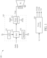
- FIG. 1 is a diagram illustrating an amplifier system 100 according to one embodiment of the present invention.
- the amplifier system 100 comprises audio amplifier 110 and a power converter 120, wherein the audio amplifier 110 comprises a low dropout regulator (LDO) 112, a digital-to-analog converter (DAC) 114, a regulator 116 and a power amplifier 118.
- the LDO 112 and the regulator 116 are configured to provide supply voltages to the DAC 114, for the DAC 114 to perform the digital-to-analog conversion operation upon an audio signal to generate an analog signal, and the power amplifier 118 amplifies the analog signal to generate an output signal Vout to drive a speaker (a resistor RL serves as a load or an equivalent resistance of the speaker).
- a resistor RL serves as a load or an equivalent resistance of the speaker.
- the amplifier system 100 is supplied by four different supply voltages, wherein an input voltage VI is provided to the LDO 112, a negative supply voltage VN is provided to the regulator 116, and supply voltages PVDD and PVSS are used by the power amplifier 118.
- the power converter 120 is configured to receive the input voltage VI to generate the other supply voltages PVDD, PVSS and VN.
- the negative supply voltage VN has a fixed voltage level
- the supply voltages PVDD and PVSS are signal-dependent supply voltages.
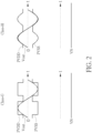
- the power amplifier 118 may be a class-G amplifier or a class-H amplifier that provides several power rails at different voltages, and the supply voltage PVDD/PVSS is controlled to at least have one of the power rails based on the information of the audio signal, to make the supply voltage PVDD/PVSS be only a few hundred-millivolts larger than the output signal Vout.
- FIG. 3 is a diagram illustrating the power converter 120 according to one embodiment of the present invention.
- the power converter 120 comprises an input capacitor C1, an inductor L, three output capacitors C2 - C4 and a plurality of switches SW1 - SW6.
- the input capacitor C1 is coupled between a node N1 and a ground voltage
- the output capacitor C2 is coupled between a node N4 and the ground voltage
- the output capacitor C3 is coupled between a node N5 and the ground voltage
- the output capacitor C4 is coupled between a node N6 and the ground voltage.
- the switch SW1 is coupled between the node N1 and a node N2, and the switch SW1 is configured to selectively connect an input voltage (i.e., the supply voltage VI) to a first terminal of the inductor L.
- the switch SW6 is coupled between the node N2 and the ground voltage, and the switch SW6 is configured to selectively connect the first terminal of the inductor L to the ground voltage.
- the switch SW3 is coupled between a node N3 and the node N4, and the switch SW3 is configured to selectively connect a second terminal of the inductor L to the node N4 to adjust a voltage level of the supply voltage PVDD.
- the switch SW2 is coupled between the node N3 and the ground voltage, and the switch SW2 is configured to selectively connect the second terminal of the inductor L to the ground voltage.
- the switch SW4 is coupled between the node N2 and the node N5, and the switch SW4 is configured to selectively connect the first terminal of the inductor L to the node N5 to adjust a voltage level of the supply voltage PVSS.
- the switch SW5 is coupled between the node N2 and the node N6, and the switch SW5 is configured to selectively connect the first terminal of the inductor L to the node N6 to stabilize a voltage level of the negative supply voltage VN.
- the controls of the switches SW1 - SW6 are based on the audio signal, the voltage levels of the supply voltages PVDD, PVSS and the negative supply voltage VN, and by controlling the switches SW1 - SW6 to control a current of the inductor L to generate the supply voltages PVDD, PVSS and the negative supply voltage VN with suitable voltage levels, the power converter 120 will have better efficiency. The details are described as follows.
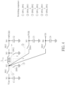
- FIG. 4 shows a control method of the switches SW1 - SW6 according to one embodiment of the present invention. Referring to FIG. 4 and FIG. 5 together, in a first period, the switches SW1 and SW2 are enabled, and the switches SW3 - SW6 are disabled.
- the inductor current I L will decrease rapidly due to the large voltage difference between two terminals of the inductor L, for example, a slope of the inductor current drop is equal to PVDD + PVSS L .
- the supply voltage PVDD rises while the supply voltage PVSS falls within the second period, so the efficiency of the power converter 120 can be improved.
- the power converter 120 switches from the second period to the third period when the inductor current I L drops to near zero.
- the switches SW6 and SW2 are enabled, and the switches S1, SW3 - SW5 are disabled.
- two terminals of the inductor L are connected to the ground voltage to make sure that the inductor current I L become zero.
- the switches SW1 - SW6 can be controlled based on the audio signal, the voltage levels of the supply voltages PVDD, PVSS and the negative supply voltage VN.
- the power converter 120 can perform the above operations corresponding to the first period to the third period again.
- FIG. 6 shows a control method of the switches SW1 - SW6 according to one embodiment of the present invention.
- the switches SW1 and SW2 are enabled, and the switches SW3 - SW6 are disabled.
- a current is flowing from the node N1, the switch SW1, the node N2, the inductor L, the node N3 and the switch SW2 to the ground voltage, and an inductor current I L is increasing.
- the switches SW5 and SW3 are enabled, and the switches SW1, SW2, SW4 and SW6 are disabled.
- the switches SW6 and SW2 are enabled, and the switches S1, SW3 - SW5 are disabled. At this time, two terminals of the inductor L are connected to the ground voltage to make sure that the inductor current I L become zero.
- the switches SW1 - SW6 can be controlled based on the audio signal, the voltage levels of the supply voltages PVDD, PVSS and the negative supply voltage VN. For example, the power converter 120 can perform the above operations corresponding to the first period to the third period again.
- the power converter 120 can have lower conduction power loss and higher efficiency.
- the power converter 120 of this embodiment has more switching times, for example, the six periods shown in FIG. 4 or FIG. 6 have eleven switching times, the power converter 120 may have higher switching power loss.
- each of the switches SW2 and SW6 can be designed to have a large part and a small part, and only the smaller parts of the switches SW2 and SW6 are enabled during the third period, to decrease the switching power loss.
- the switch SW2 shown in FIG. 3 can be implemented by using a large switch SW2L and a small switch SW2S, wherein the large switch SW2L is coupled between the node N2 and the ground voltage, and the small switch SW6S is coupled between the node N2 and the ground voltage.
- the large switch SW6L has a large size and larger current when it is enabled
- the small switch SW6S has a small size and smaller current when it is enabled.
- the switch SW2 shown in FIG. 3 can be implemented by using a large switch SW2L and a small switch SW2S, wherein the large switch SW2L is coupled between the node N2 and the ground voltage, and the small switch SW2S is coupled between the node N2 and the ground voltage.
- the large switch SW2L has a large size and larger current when it is enabled
- the small switch SW2S has a small size and smaller current when it is enabled.
- the switches SW1 and SW2 are enabled (in the switch SW2, at least the large switch SW2L is enabled), and the switches SW3 - SW6 are disabled.
- a current is flowing from the node N1, the switch SW1, the node N2, the inductor L, the node N3 and the large switch SW2 to the ground voltage, and an inductor current I L is increasing.
- the switches SW4 and SW3 are enabled, and the switches SW1, SW2, SW5 and SW6 are disabled.
- the switches SW1 and SW2 are enabled (in the switch SW2, at least the large switch SW2L is enabled), and the switches SW3 - SW6 are disabled.
- a current is flowing from the node N1, the switch SW1, the node N2, the inductor L, the node N3 and the large switch SW2 to the ground voltage, and an inductor current I L is increasing.
- the switches SW5 and SW3 are enabled, and the switches SW1, SW2, SW4 and SW6 are disabled.
- the small switches SW6S and SW2S are enough for the operation.
- the small switches SW6S and SW2S have low switching power loss, by only enabling the small switches SW6S and SW2S in the third period, the overall switching power loss can be effectively reduced.
- the power converter 120 is configured to receive the input voltage VI to generate three supply voltages PVDD, PVSS and VN.
- the switch SW6, the node N6 and the output capacitor C4 can be removed from the power converter 120, that is the power converter 120 is configured to receive the input voltage VI to generate two supply voltages PVDD and PVSS. This alternative design shall fall within the scope of the present invention.
- the power converter of the amplifier system of the present invention only one inductor is used to generate two or three supply voltages, so the power converter can have a lower manufacturing cost.
- the power converter has higher efficiency, lower conduction power loss and lower switching power loss.
Landscapes
- Engineering & Computer Science (AREA)
- Power Engineering (AREA)
- Multimedia (AREA)
- Amplifiers (AREA)
Abstract
Description
- This application claims the benefit of
U.S. Provisional Application No. 63/299,422, filed on January 14th, 2022 - In a conventional audio amplifier, two or more supply voltages are required for the audio amplifier to process a digital input audio signal to generate an analog output audio signal. In order to generate the two or more supply voltages, a power converter is generally designed to have two or more inductors, which increases the form factor and manufacturing costs.
- It is therefore an objective of the present invention to provide an audio amplifier and related power converter, wherein the power converter can use only one inductor to generate two or three supply voltages for use of the audio amplifier, and the power converter has higher efficiency, to solve the above-mentioned problems.
- According to one embodiment of the present invention, an amplifier system comprising an audio amplifier and a power converter is disclosed. The audio amplifier is supplied by at least a first supply voltage and a second supply voltage, and the audio amplifier is configured to receive an audio signal to generate an output signal. The power converter comprises only one inductor, and is configured to generate the first supply voltage and the second supply voltage according to an input voltage.
- According to one embodiment of the present invention, a power converter is disclosed. The power converter is configured to receive an input voltage to generate a first supply voltage and a second supply voltage, and the power converter comprises an inductor, a first switch, a second switch, a third switch, a fourth switch and a fifth switch. The inductor has a first terminal and a second terminal; the first switch is configured to selectively connect the input voltage to the first terminal of the inductor; the second switch is configured to selectively connect the second terminal of the inductor to a ground voltage; the third switch is configured to selectively connect the second terminal of the inductor to the first supply voltage; the fourth switch is configured to selectively connect the first terminal of the inductor to the second supply voltage; and the fifth switch is configured to selectively connect the first terminal of the inductor to the ground voltage.
- These and other objectives of the present invention will no doubt become obvious to those of ordinary skill in the art after reading the following detailed description of the preferred embodiment that is illustrated in the various figures and drawings.
-
-
FIG. 1 is a diagram illustrating an amplifier system according to one embodiment of the present invention. -
FIG. 2 shows supply voltages of the audio amplifier for class-G and class-H amplifier. -
FIG. 3 is a diagram illustrating a power converter according to one embodiment of the present invention. -
FIG. 4 shows a control method of the power converter according to one embodiment of the present invention. -
FIG. 5 shows the inductor current in the power converter according to one embodiment of the present invention. -
FIG. 6 shows a control method of the power converter according to one embodiment of the present invention. -
FIG. 7 is a diagram illustrating another power converter according to one embodiment of the present invention. - Certain terms are used throughout the following description and claims to refer to particular system components. As one skilled in the art will appreciate, manufacturers may refer to a component by different names. This document does not intend to distinguish between components that differ in name but not function. In the following discussion and in the claims, the terms "including" and "comprising" are used in an open-ended fashion, and thus should be interpreted to mean "including, but not limited to ...". The terms "couple" and "couples" are intended to mean either an indirect or a direct electrical connection. Thus, if a first device couples to a second device, that connection may be through a direct electrical connection, or through an indirect electrical connection via other devices and connections.
-
FIG. 1 is a diagram illustrating anamplifier system 100 according to one embodiment of the present invention. As shown inFIG. 1 , theamplifier system 100 comprisesaudio amplifier 110 and apower converter 120, wherein theaudio amplifier 110 comprises a low dropout regulator (LDO) 112, a digital-to-analog converter (DAC) 114, aregulator 116 and apower amplifier 118. The LDO 112 and theregulator 116 are configured to provide supply voltages to theDAC 114, for theDAC 114 to perform the digital-to-analog conversion operation upon an audio signal to generate an analog signal, and thepower amplifier 118 amplifies the analog signal to generate an output signal Vout to drive a speaker (a resistor RL serves as a load or an equivalent resistance of the speaker). In this embodiment, theamplifier system 100 is supplied by four different supply voltages, wherein an input voltage VI is provided to theLDO 112, a negative supply voltage VN is provided to theregulator 116, and supply voltages PVDD and PVSS are used by thepower amplifier 118. In addition, thepower converter 120 is configured to receive the input voltage VI to generate the other supply voltages PVDD, PVSS and VN. - In one embodiment, the negative supply voltage VN has a fixed voltage level, and the supply voltages PVDD and PVSS are signal-dependent supply voltages. For example, referring to
FIG. 2 , thepower amplifier 118 may be a class-G amplifier or a class-H amplifier that provides several power rails at different voltages, and the supply voltage PVDD/PVSS is controlled to at least have one of the power rails based on the information of the audio signal, to make the supply voltage PVDD/PVSS be only a few hundred-millivolts larger than the output signal Vout. -
FIG. 3 is a diagram illustrating thepower converter 120 according to one embodiment of the present invention. As shown inFIG. 3 , thepower converter 120 comprises an input capacitor C1, an inductor L, three output capacitors C2 - C4 and a plurality of switches SW1 - SW6. The input capacitor C1 is coupled between a node N1 and a ground voltage, the output capacitor C2 is coupled between a node N4 and the ground voltage, the output capacitor C3 is coupled between a node N5 and the ground voltage, and the output capacitor C4 is coupled between a node N6 and the ground voltage. The switch SW1 is coupled between the node N1 and a node N2, and the switch SW1 is configured to selectively connect an input voltage (i.e., the supply voltage VI) to a first terminal of the inductor L. The switch SW6 is coupled between the node N2 and the ground voltage, and the switch SW6 is configured to selectively connect the first terminal of the inductor L to the ground voltage. The switch SW3 is coupled between a node N3 and the node N4, and the switch SW3 is configured to selectively connect a second terminal of the inductor L to the node N4 to adjust a voltage level of the supply voltage PVDD. The switch SW2 is coupled between the node N3 and the ground voltage, and the switch SW2 is configured to selectively connect the second terminal of the inductor L to the ground voltage. The switch SW4 is coupled between the node N2 and the node N5, and the switch SW4 is configured to selectively connect the first terminal of the inductor L to the node N5 to adjust a voltage level of the supply voltage PVSS. The switch SW5 is coupled between the node N2 and the node N6, and the switch SW5 is configured to selectively connect the first terminal of the inductor L to the node N6 to stabilize a voltage level of the negative supply voltage VN. - In the
power converter 120 shown inFIG. 1 , because only one inductor L is used to generate the supply voltages PVDD, PVSS and the negative supply voltage VN, the form factor and manufacturing cost of thepower converter 120 can be reduced. In addition, the controls of the switches SW1 - SW6 are based on the audio signal, the voltage levels of the supply voltages PVDD, PVSS and the negative supply voltage VN, and by controlling the switches SW1 - SW6 to control a current of the inductor L to generate the supply voltages PVDD, PVSS and the negative supply voltage VN with suitable voltage levels, thepower converter 120 will have better efficiency. The details are described as follows. - When the load RL shown in
FIG. 1 is a full-bridge load, there is a current path through the load RL between the supply voltages PVDD and PVSS, and the level of the supply voltage PVDD will drop while the level of the supply voltage PVSS will rise. To make the supply voltages PVDD and PVSS have the desired voltage levels with higher efficiency,FIG. 4 shows a control method of the switches SW1 - SW6 according to one embodiment of the present invention. Referring toFIG. 4 andFIG. 5 together, in a first period, the switches SW1 and SW2 are enabled, and the switches SW3 - SW6 are disabled. At this time, a current is flowing from the node N1, the switch SW1, the node N2, the inductor L, the node N3 and the switch SW2 to the ground voltage, and an inductor current IL is increasing. In a second period immediately following the first period, the switches SW4 and SW3 are enabled, and the switches SW1, SW2, SW5 and SW6 are disabled. At this time, a current is flowing from the node N5, the switch SW4, the node N2, the inductor L, the node N3, the switch SW3 to the node N4, and the inductor current IL is decreasing. In the second period, because the supply voltage PVDD is coupled to the supply voltage PVSS through the inductor L, the inductor current IL will decrease rapidly due to the large voltage difference between two terminals of the inductor L, for example, a slope of the inductor current drop is equal to
- Referring to
FIG. 5 , in the first period and the second period, the conduction power loss of the switches can be represented in the following formula:
power converter 120 have lower conduction power loss. - In addition, the supply voltage PVDD rises while the supply voltage PVSS falls within the second period, so the efficiency of the
power converter 120 can be improved. - The
power converter 120 switches from the second period to the third period when the inductor current IL drops to near zero. In a third period immediately following the second period, the switches SW6 and SW2 are enabled, and the switches S1, SW3 - SW5 are disabled. At this time, two terminals of the inductor L are connected to the ground voltage to make sure that the inductor current IL become zero. After the third period, the switches SW1 - SW6 can be controlled based on the audio signal, the voltage levels of the supply voltages PVDD, PVSS and the negative supply voltage VN. For example, thepower converter 120 can perform the above operations corresponding to the first period to the third period again. - In one embodiment, when the level of the supply voltage PVDD is lower than the desired level while the negative supply voltage VN is above its desired level,
FIG. 6 shows a control method of the switches SW1 - SW6 according to one embodiment of the present invention. Referring toFIG. 6 , in a first period, the switches SW1 and SW2 are enabled, and the switches SW3 - SW6 are disabled. At this time, a current is flowing from the node N1, the switch SW1, the node N2, the inductor L, the node N3 and the switch SW2 to the ground voltage, and an inductor current IL is increasing. In a second period immediately following the first period, the switches SW5 and SW3 are enabled, and the switches SW1, SW2, SW4 and SW6 are disabled. At this time, a current is flowing from the node N6, the switch SW5, the node N2, the inductor L, the node N3, the switch SW3 to the node N4, and the inductor current IL is decreasing. In the second period, because the supply voltage PVDD is coupled to the supply voltage PVSS through the inductor L, the inductor current IL will decrease rapidly due to the large voltage difference between two terminals of the inductor L. Referring to the above formula (1), because the embodiment has a larger slope of the inductor current drop, the parameter "TOFF" in the formula (1) will have a smaller value, so that the switches in thepower converter 120 have lower conduction power loss. - In a third period immediately following the second period, the switches SW6 and SW2 are enabled, and the switches S1, SW3 - SW5 are disabled. At this time, two terminals of the inductor L are connected to the ground voltage to make sure that the inductor current IL become zero. After the third period, the switches SW1 - SW6 can be controlled based on the audio signal, the voltage levels of the supply voltages PVDD, PVSS and the negative supply voltage VN. For example, the
power converter 120 can perform the above operations corresponding to the first period to the third period again. - In the above embodiments shown in
FIG. 4 - FIG. 6 , by connecting the supply voltage PVSS to the supply voltage PVDD or connecting the negative supply voltage VN to the supply voltage PVDD in the second period, thepower converter 120 can have lower conduction power loss and higher efficiency. However, because thepower converter 120 of this embodiment has more switching times, for example, the six periods shown inFIG. 4 orFIG. 6 have eleven switching times, thepower converter 120 may have higher switching power loss. To solve this problem, each of the switches SW2 and SW6 can be designed to have a large part and a small part, and only the smaller parts of the switches SW2 and SW6 are enabled during the third period, to decrease the switching power loss. Specifically, referring toFIG. 7 , the switch SW6 shown inFIG. 3 can be implemented by using a large switch SW6L and a small switch SW6S, wherein the large switch SW6L is coupled between the node N2 and the ground voltage, and the small switch SW6S is coupled between the node N2 and the ground voltage. In this embodiment, the large switch SW6L has a large size and larger current when it is enabled, and the small switch SW6S has a small size and smaller current when it is enabled. Similarly, the switch SW2 shown inFIG. 3 can be implemented by using a large switch SW2L and a small switch SW2S, wherein the large switch SW2L is coupled between the node N2 and the ground voltage, and the small switch SW2S is coupled between the node N2 and the ground voltage. In this embodiment, the large switch SW2L has a large size and larger current when it is enabled, and the small switch SW2S has a small size and smaller current when it is enabled. - In the embodiment shown in
FIG. 7 , when the level of the supply voltage PVDD is lower than the desired level while the supply voltage PVSS is above its desired level, in a first period, the switches SW1 and SW2 are enabled (in the switch SW2, at least the large switch SW2L is enabled), and the switches SW3 - SW6 are disabled. At this time, a current is flowing from the node N1, the switch SW1, the node N2, the inductor L, the node N3 and the large switch SW2 to the ground voltage, and an inductor current IL is increasing. In a second period immediately following the first period, the switches SW4 and SW3 are enabled, and the switches SW1, SW2, SW5 and SW6 are disabled. At this time, a current is flowing from the node N5, the switch SW4, the node N2, the inductor L, the node N3, the switch SW3 to the node N4, and the inductor current IL is decreasing. In a third period immediately following the second period, only the small switches SW6S and SW2S are enabled, and the switches S1, SW3 - SW5, the large switch SW6L and SW2L are disabled. At this time, two terminals of the inductor L are connected to the ground voltage to make sure that the inductor current IL become zero. After the third period, the switches SW1 - SW6 can be controlled based on the audio signal, the voltage levels of the supply voltages PVDD, PVSS and the negative supply voltage VN. For example, thepower converter 120 can perform the above operations corresponding to the first period to the third period again. - In another embodiment shown in
FIG. 7 , when the level of the supply voltage PVDD is lower than the desired level while the negative supply voltage VN is above its desired level, in a first period, the switches SW1 and SW2 are enabled (in the switch SW2, at least the large switch SW2L is enabled), and the switches SW3 - SW6 are disabled. At this time, a current is flowing from the node N1, the switch SW1, the node N2, the inductor L, the node N3 and the large switch SW2 to the ground voltage, and an inductor current IL is increasing. In a second period immediately following the first period, the switches SW5 and SW3 are enabled, and the switches SW1, SW2, SW4 and SW6 are disabled. At this time, a current is flowing from the node N6, the switch SW5, the node N2, the inductor L, the node N3, the switch SW3 to the node N4, and the inductor current IL is decreasing. In a third period immediately following the second period, only the small switches SW6S and SW2S are enabled, and the switches S1, SW3 - SW5, the large switch SW6L and SW2L are disabled. At this time, two terminals of the inductor L are connected to the ground voltage to make sure that the inductor current IL become zero. After the third period, the switches SW1 - SW6 can be controlled based on the audio signal, the voltage levels of the supply voltages PVDD, PVSS and the negative supply voltage VN. For example, thepower converter 120 can perform the above operations corresponding to the first period to the third period again. - In the above two embodiments, because the inductor current IL is very small in the inductor-current freewheeling period (i.e., the above third period), the small switches SW6S and SW2S are enough for the operation. In addition, because the small switches SW6S and SW2S have low switching power loss, by only enabling the small switches SW6S and SW2S in the third period, the overall switching power loss can be effectively reduced.
- In the above embodiments, the
power converter 120 is configured to receive the input voltage VI to generate three supply voltages PVDD, PVSS and VN. In another embodiment, the switch SW6, the node N6 and the output capacitor C4 can be removed from thepower converter 120, that is thepower converter 120 is configured to receive the input voltage VI to generate two supply voltages PVDD and PVSS. This alternative design shall fall within the scope of the present invention. - Briefly summarized, in the power converter of the amplifier system of the present invention, only one inductor is used to generate two or three supply voltages, so the power converter can have a lower manufacturing cost. In addition, by using a specific switch control method proposed in the embodiments of the present invention, the power converter has higher efficiency, lower conduction power loss and lower switching power loss.
- Those skilled in the art will readily observe that numerous modifications and alterations of the device and method may be made while retaining the teachings of the invention. Accordingly, the above disclosure should be construed as limited only by the metes and bounds of the appended claims.
- The present application may also be defined by the following numbered clauses.
- 1. An amplifier system, comprising:
- an audio amplifier supplied by at least a first supply voltage and a second supply voltage, configured to receive an audio signal to generate an output signal; and
- a power converter comprising only one inductor, configured to generate the first supply voltage and the second supply voltage according to an input voltage.
- 2. The amplifier system of
clause 1, wherein the first supply voltage and the second supply voltage are signal-dependent supply voltages whose voltage levels are determined according to the audio signal. - 3. The amplifier system of
clause 1, wherein the power converter comprises:
an inductor, wherein a first terminal of the inductor is selectively coupled to the input voltage or the first supply voltage, and a second terminal of the inductor is selectively coupled to the second supply voltage. - 4. The amplifier system of
clause 3, wherein in a first period, the input voltage is inputted to the inductor and an inductor current is increasing; in a second period following the first period, the input voltage is disconnected from the inductor, and the second supply voltage is coupled to the first supply voltage through the inductor, and the inductor current is decreasing; and in a third period following the second period, the input voltage, the first supply voltage and the second supply voltage are disconnected from the inductor. - 5. The amplifier system of
clause 3, wherein the power converter further comprises:- a first switch, configured to selectively connect the input voltage to the first terminal of the inductor;
- a second switch, configured to selectively connect the second terminal of the inductor to a ground voltage;
- a third switch, configured to selectively connect the second terminal of the inductor to the first supply voltage;
- a fourth switch, configured to selectively connect the first terminal of the inductor to the second supply voltage; and
- a fifth switch, configured to selectively connect the first terminal of the inductor to the ground voltage.
- 6. The amplifier system of clause 5, wherein in a first period, the first switch and the second switch are enabled, the third switch, the fourth switch and the fifth switch are disabled, and the input voltage is inputted to the inductor and an inductor current is increasing; in a second period following the first period, the third switch and the fourth switch are enabled, the first switch, the second switch and the fifth switch are disabled, and the second supply voltage is coupled to the first supply voltage through the inductor, and the inductor current is decreasing; and in a third period following the second period, the second switch and the fifth switch are enabled, and the first switch, the third switch and the fourth switch are disabled.
- 7. The amplifier system of clause 6, wherein the second switch comprises a large switch and a small switch, wherein the large switch is configured to selectively connect the second terminal of the inductor to the ground voltage, the small switch is configured to selectively connect the second terminal of the inductor to the ground voltage, and a current of the large switch is greater than a current of the small switch; and in the third period following the second period, only the small switch is enabled, and the large switch is disabled.
- 8. The amplifier system of clause 6, wherein the fifth switch comprises a large switch and a small switch, wherein the large switch is configured to selectively connect the second terminal of the inductor to the ground voltage, the small switch is configured to selectively connect the second terminal of the inductor to the ground voltage, and a current of the large switch is greater than a current of the small switch; and in the third period following the second period, only the small switch is enabled, and the large switch is disabled.
- 9. The amplifier system of
clause 1, wherein the audio amplifier is supplied by the first supply voltage, the second supply voltage and a negative supply voltage, and the power converter is configured to generate the first supply voltage, the second supply voltage and the negative supply voltage according to the input voltage, wherein the first supply voltage and the second supply voltage are signal-dependent supply voltages whose voltage levels are determined according to the audio signal, and the negative supply voltage has a fixed voltage level. - 10. The amplifier system of clause 9, wherein the power converter comprises:
- an inductor having a first terminal and second terminal;
- a first switch, configured to selectively connect the input voltage to the first terminal of the inductor;
- a second switch, configured to selectively connect the second terminal of the inductor to a ground voltage;
- a third switch, configured to selectively connect the second terminal of the inductor to the first supply voltage;
- a fourth switch, configured to selectively connect the first terminal of the inductor to the second supply voltage;
- a fifth switch, configured to selectively connect the first terminal of the inductor to the negative supply voltage; and
- a sixth switch, configured to selectively connect the first terminal of the inductor to the ground voltage.
- 11. The amplifier system of clause 10, wherein in a first period, the first switch and the second switch are enabled, the third switch, the fourth switch, the fifth switch and the sixth switch are disabled, and the input voltage is inputted to the inductor and an inductor current is increasing; in a second period following the first period, the third switch and the fourth switch are enabled, the first switch, the second switch, the fifth switch and the sixth switch are disabled, and the second supply voltage is coupled to the first supply voltage through the inductor, and the inductor current is decreasing; and in a third period following the second period, the second switch and the sixth switch are enabled, and the first switch, the third switch, the fourth switch and the fifth switch are disabled.
- 12. The amplifier system of clause 10, wherein in a first period, the first switch and the second switch are enabled, the third switch, the fourth switch, the fifth switch and the sixth switch are disabled, and the input voltage is inputted to the inductor and an inductor current is increasing; in a second period following the first period, the third switch and the fifth switch are enabled, the first switch, the second switch, the fourth switch and the sixth switch are disabled, and the second supply voltage is coupled to the first supply voltage through the inductor, and the inductor current is decreasing; and in a third period following the second period, the second switch and the sixth switch are enabled, and the first switch, the third switch, the fourth switch and the fifth switch are disabled.
- 13. A power converter configured to receive an input voltage to generate a first supply voltage, a second supply voltage, and a third supply voltage, comprising:
- an inductor having a first terminal and a second terminal;
- a first switch, configured to selectively connect the input voltage to the first terminal of the inductor;
- a second switch, configured to selectively connect the second terminal of the inductor to a ground voltage;
- a third switch, configured to selectively connect the second terminal of the inductor to the first supply voltage;
- a fourth switch, configured to selectively connect the first terminal of the inductor to the second supply voltage;
- a fifth switch, configured to selectively connect the first terminal of the inductor to the third voltage; and
- a sixth switch, configured to selectively connect the first terminal of the inductor to the ground voltage.
- 14. The power converter of clause 13,wherein in a first period, the first switch and the second switch are enabled, the third switch, the fourth switch, the fifth switch and the sixth switch are disabled, and the input voltage is inputted to the inductor and an inductor current is increasing; in a second period following the first period, the third switch and the fourth switch are enabled, the first switch, the second switch, the fifth switch and the sixth switch are disabled, and the second supply voltage is coupled to the first supply voltage through the inductor, and the inductor current is decreasing; and in a third period following the second period, the second switch and the sixth switch are enabled, and the first switch, the third switch, the fourth switch and the fifth switch are disabled.
- 15. The power converter of clause 14, wherein the sixth switch comprises a large switch and a small switch, wherein the large switch is configured to selectively connect the second terminal of the inductor to the ground voltage, the small switch is configured to selectively connect the second terminal of the inductor to the ground voltage, and a current of the large switch is greater than a current of the small switch; and in the third period following the second period, only the small switch is enabled, and the large switch is disabled.
- 16. The power converter of clause 14, the second switch comprises a large switch and a small switch, wherein the large switch is configured to selectively connect the second terminal of the inductor to the ground voltage, the small switch is configured to selectively connect the second terminal of the inductor to the ground voltage, and a current of the large switch is greater than a current of the small switch; and in the third period following the second period, only the small switch is enabled, and the large switch is disabled.
- 17. The power converter of clause 14, wherein the audio amplifier is supplied by the first supply voltage, the second supply voltage and a negative supply voltage, and the power converter is configured to generate the first supply voltage, the second supply voltage and the negative supply voltage according to the input voltage, wherein the first supply voltage and the second supply voltage are signal-dependent supply voltages whose voltage levels are determined according to the audio signal, and the negative supply voltage has a fixed voltage level.
Claims (15)
- An amplifier system (100), comprising:an audio amplifier supplied by at least a first supply voltage and a second supply voltage, configured to receive an audio signal to generate an output signal; anda power converter (120) comprising only one inductor, configured to generate the first supply voltage and the second supply voltage according to an input voltage.
- The amplifier system (100) of claim 1, wherein the first supply voltage and the second supply voltage are signal-dependent supply voltages whose voltage levels are determined according to the audio signal.
- The amplifier system (100) of claim 1, wherein the power converter (120) comprises:
an inductor (L), wherein a first terminal of the inductor (L) is selectively coupled to the input voltage or the first supply voltage, and a second terminal of the inductor (L) is selectively coupled to the second supply voltage. - The amplifier system (100) of claim 3, wherein in a first period, the input voltage is inputted to the inductor (L) and an inductor (L) current is increasing; in a second period following the first period, the input voltage is disconnected from the inductor (L), and the second supply voltage is coupled to the first supply voltage through the inductor (L), and the inductor (L) current is decreasing; and in a third period following the second period, the input voltage, the first supply voltage and the second supply voltage are disconnected from the inductor (L).
- The amplifier system (100) of claim 3, wherein the power converter (120) further comprises:a first switch (SW1), configured to selectively connect the input voltage to the first terminal of the inductor (L);a second switch (SW2), configured to selectively connect the second terminal of the inductor (L) to a ground voltage;a third switch (SW3), configured to selectively connect the second terminal of the inductor (L) to the first supply voltage;a fourth switch (SW4), configured to selectively connect the first terminal of the inductor (L) to the second supply voltage; anda fifth switch (SW5), configured to selectively connect the first terminal of the inductor (L) to the ground voltage.
- The amplifier system (100) of claim 5, wherein in a first period, the first switch (SW1) and the second switch (SW2) are enabled, the third switch (SW3), the fourth switch (SW4) and the fifth switch (SW5) are disabled, and the input voltage is inputted to the inductor (L) and an inductor current (IL) is increasing; in a second period following the first period, the third switch (SW3) and the fourth switch (SW4) are enabled, the first switch (SW1), the second switch (SW2) and the fifth switch (SW5) are disabled, and the second supply voltage is coupled to the first supply voltage through the inductor (L), and the inductor current (IL) is decreasing; and in a third period following the second period, the second switch (SW2) and the fifth switch (SW5) are enabled, and the first switch (SW1), the third switch (SW3) and the fourth switch (SW4) are disabled.
- The amplifier system (100) of claim 6, wherein the second switch comprises a large switch and a small switch, wherein the large switch is configured to selectively connect the second terminal of the inductor (L) to the ground voltage, the small switch is configured to selectively connect the second terminal of the inductor (L) to the ground voltage, and a current of the large switch is greater than a current of the small switch; and in the third period following the second period, only the small switch is enabled, and the large switch is disabled; or
wherein the fifth switch (SW5) comprises a large switch and a small switch, wherein the large switch is configured to selectively connect the second terminal of the inductor (L) to the ground voltage, the small switch is configured to selectively connect the second terminal of the inductor (L) to the ground voltage, and a current of the large switch is greater than a current of the small switch; and in the third period following the second period, only the small switch is enabled, and the large switch is disabled. - The amplifier system (100) of claim 1, wherein the audio amplifier is supplied by the first supply voltage, the second supply voltage and a negative supply voltage, and the power converter (120) is configured to generate the first supply voltage, the second supply voltage and the negative supply voltage according to the input voltage, wherein the first supply voltage and the second supply voltage are signal-dependent supply voltages whose voltage levels are determined according to the audio signal, and the negative supply voltage has a fixed voltage level.
- The amplifier system (100) of claim 8, wherein the power converter (120) comprises:an inductor (L) having a first terminal and second terminal;a first switch (SW1), configured to selectively connect the input voltage to the first terminal of the inductor (L);a second switch (SW2), configured to selectively connect the second terminal of the inductor (L) to a ground voltage;a third switch (SW3), configured to selectively connect the second terminal of the inductor (L) to the first supply voltage;a fourth switch (SW4), configured to selectively connect the first terminal of the inductor (L) to the second supply voltage;a fifth switch (SW5), configured to selectively connect the first terminal of the inductor (L) to the negative supply voltage; anda sixth switch (SW6), configured to selectively connect the first terminal of the inductor (L) to the ground voltage.
- The amplifier system (100) of claim 9, wherein in a first period, the first switch (SW1) and the second switch (SW2) are enabled, the third switch (SW3), the fourth switch (SW4), the fifth switch (SW5) and the sixth switch (SW6) are disabled, and the input voltage is inputted to the inductor (L) and an inductor current (IL) is increasing; in a second period following the first period, the third switch (SW3) and the fourth switch (SW4) are enabled, the first switch (SW1), the second switch (SW2), the fifth switch (SW5) and the sixth switch (SW6) are disabled, and the second supply voltage is coupled to the first supply voltage through the inductor (L), and the inductor current (IL) is decreasing; and in a third period following the second period, the second switch (SW2) and the sixth switch (SW6) are enabled, and the first switch (SW1), the third switch (SW3), the fourth switch (SW4) and the fifth switch (SW5) are disabled.
- The amplifier system (100) of claim 9, wherein in a first period, the first switch (SW1) and the second switch (SW2) are enabled, the third switch (SW3), the fourth switch (SW4), the fifth switch (SW5) and the sixth switch (SW6) are disabled, and the input voltage is inputted to the inductor (L) and an inductor current (IL) is increasing; in a second period following the first period, the third switch (SW3) and the fifth switch (SW5) are enabled, the first switch (SW1), the second switch (SW2), the fourth switch (SW4)and the sixth switch (SW6) are disabled, and the second supply voltage is coupled to the first supply voltage through the inductor (L), and the inductor current (IL) is decreasing; and in a third period following the second period, the second switch (SW2) and the sixth switch (SW6) are enabled, and the first switch (SW1), the third switch (SW3), the fourth switch (SW4) and the fifth switch (SW5) are disabled.
- A power converter (120) configured to receive an input voltage to generate a first supply voltage, a second supply voltage, and a third supply voltage, comprising:an inductor (L) having a first terminal and a second terminal;a first switch (SW1), configured to selectively connect the input voltage to the first terminal of the inductor;a second switch (SW2), configured to selectively connect the second terminal of the inductor (L) to a ground voltage;a third switch (SW3), configured to selectively connect the second terminal of the inductor (L) to the first supply voltage;a fourth switch (SW4), configured to selectively connect the first terminal of the inductor (L) to the second supply voltage;a fifth switch (SW5), configured to selectively connect the first terminal of the inductor (L) to the third voltage; anda sixth switch (SW6), configured to selectively connect the first terminal of the inductor (L) to the ground voltage.
- The power converter (120) of claim 12, wherein in a first period, the first switch (SW1) and the second switch (SW2) are enabled, the third switch (SW3), the fourth switch (SW4), the fifth switch (SW5) and the sixth switch (SW6) are disabled, and the input voltage is inputted to the inductor (L) and an inductor current (IL) is increasing; in a second period following the first period, the third switch (SW3) and the fourth switch (SW4) are enabled, the first switch (SW1), the second switch (SW2), the fifth switch (SW5) and the sixth switch (SW6) are disabled, and the second supply voltage is coupled to the first supply voltage through the inductor (L), and the inductor current (IL) is decreasing; and in a third period following the second period, the second switch (SW2) and the sixth switch (SW6) are enabled, and the first switch (SW1), the third switch (SW3), the fourth switch (SW4)and the fifth switch (SW5)are disabled.
- The power converter (120) of claim 13, wherein the sixth switch (SW6) comprises a large switch and a small switch, wherein the large switch is configured to selectively connect the second terminal of the inductor (L) to the ground voltage, the small switch is configured to selectively connect the second terminal of the inductor (L) to the ground voltage, and a current of the large switch is greater than a current of the small switch; and in the third period following the second period, only the small switch is enabled, and the large switch is disabled.
- The power converter (120) of claim 13, the second switch (SW2) comprises a large switch and a small switch, wherein the large switch is configured to selectively connect the second terminal of the inductor (L) to the ground voltage, the small switch is configured to selectively connect the second terminal of the inductor (L) to the ground voltage, and a current of the large switch is greater than a current of the small switch; and in the third period following the second period, only the small switch is enabled, and the large switch is disabled; or
wherein the audio amplifier is supplied by the first supply voltage, the second supply voltage and a negative supply voltage, and the power converter (120) is configured to generate the first supply voltage, the second supply voltage and the negative supply voltage according to the input voltage, wherein the first supply voltage and the second supply voltage are signal-dependent supply voltages whose voltage levels are determined according to the audio signal, and the negative supply voltage has a fixed voltage level.
Applications Claiming Priority (2)
| Application Number | Priority Date | Filing Date | Title |
|---|---|---|---|
| US202263299422P | 2022-01-14 | 2022-01-14 | |
| US18/085,579 US12519432B2 (en) | 2022-01-14 | 2022-12-21 | Power converter and associated control method for high-efficiency audio amplifier |
Publications (1)
| Publication Number | Publication Date |
|---|---|
| EP4213380A1 true EP4213380A1 (en) | 2023-07-19 |
Family
ID=84689021
Family Applications (1)
| Application Number | Title | Priority Date | Filing Date |
|---|---|---|---|
| EP22217143.1A Pending EP4213380A1 (en) | 2022-01-14 | 2022-12-29 | Power converter and associated control method for high-efficiency audio amplifier |
Country Status (3)
| Country | Link |
|---|---|
| US (2) | US12519432B2 (en) |
| EP (1) | EP4213380A1 (en) |
| TW (1) | TWI833545B (en) |
Citations (3)
| Publication number | Priority date | Publication date | Assignee | Title |
|---|---|---|---|---|
| US20110084760A1 (en) * | 2009-10-09 | 2011-04-14 | Richtek Technology Corp. | Highly efficient class-g amplifier and control method thereof |
| CN102751868B (en) * | 2011-07-07 | 2015-05-13 | 矽创电子股份有限公司 | Voltage converter |
| US20210408908A1 (en) * | 2020-06-30 | 2021-12-30 | Analog Devices International Unlimited Company | Inductor current dependent pulse width modulator in a simo converter |
Family Cites Families (8)
| Publication number | Priority date | Publication date | Assignee | Title |
|---|---|---|---|---|
| US7276886B2 (en) | 2005-10-03 | 2007-10-02 | Texas Instruments Incorporated | Dual buck-boost converter with single inductor |
| US20070139121A1 (en) * | 2005-12-21 | 2007-06-21 | Texas Instruments Incorporated | Amplifier symmetric supply regulation |
| KR101786587B1 (en) | 2011-10-14 | 2017-10-19 | 삼성전자주식회사 | Apparatus and method for modulating supply of power amplifier |
| US9189002B1 (en) | 2012-12-20 | 2015-11-17 | Maxim Integrated Products, Inc. | Single-inductor power converter with buck-boost capability |
| US9837901B1 (en) | 2015-06-22 | 2017-12-05 | Maxim Integrated Products, Inc. | Single-input multiple-output inverting and non-inverting buck/boost switching regulator control method and apparatus |
| EP3242385A1 (en) | 2016-05-06 | 2017-11-08 | Merus Audio ApS | A load adaptable boost dc-dc power converter |
| US20170373600A1 (en) | 2016-06-23 | 2017-12-28 | Cirrus Logic International Semiconductor Ltd. | Multi-mode switching power converter |
| US20190334750A1 (en) | 2018-04-30 | 2019-10-31 | Samsung Electronics Co., Ltd. | Symbol power tracking amplification system and a wireless communication device including the same |
-
2022
- 2022-12-21 US US18/085,579 patent/US12519432B2/en active Active
- 2022-12-29 EP EP22217143.1A patent/EP4213380A1/en active Pending
-
2023
- 2023-01-11 TW TW112101159A patent/TWI833545B/en active
-
2025
- 2025-12-14 US US19/419,072 patent/US20260106580A1/en active Pending
Patent Citations (3)
| Publication number | Priority date | Publication date | Assignee | Title |
|---|---|---|---|---|
| US20110084760A1 (en) * | 2009-10-09 | 2011-04-14 | Richtek Technology Corp. | Highly efficient class-g amplifier and control method thereof |
| CN102751868B (en) * | 2011-07-07 | 2015-05-13 | 矽创电子股份有限公司 | Voltage converter |
| US20210408908A1 (en) * | 2020-06-30 | 2021-12-30 | Analog Devices International Unlimited Company | Inductor current dependent pulse width modulator in a simo converter |
Non-Patent Citations (1)
| Title |
|---|
| XAVIER BRANCA ET AL: "Single-Inductor Bipolar-Outputs Converter for the Supply of Audio Amplifiers in Mobile Platforms", IEEE TRANSACTIONS ON POWER ELECTRONICS, INSTITUTE OF ELECTRICAL AND ELECTRONICS ENGINEERS, USA, vol. 28, no. 9, 2 September 2013 (2013-09-02), pages 4248 - 4259, XP011494221, ISSN: 0885-8993, DOI: 10.1109/TPEL.2013.2238252 * |
Also Published As
| Publication number | Publication date |
|---|---|
| US20230231523A1 (en) | 2023-07-20 |
| TWI833545B (en) | 2024-02-21 |
| US12519432B2 (en) | 2026-01-06 |
| US20260106580A1 (en) | 2026-04-16 |
| TW202329610A (en) | 2023-07-16 |
Similar Documents
| Publication | Publication Date | Title |
|---|---|---|
| US7508176B2 (en) | Controller for a DC to DC converter having linear mode and switch mode capabilities | |
| US10199928B1 (en) | Soft start of switched capacitor converters by reducing voltage provided by initial power switch | |
| US6381159B2 (en) | Inductor current synthesizer for switching power supplies | |
| US6150798A (en) | Voltage regulator | |
| CN108306489A (en) | Drive circuit, control circuit and drive method of buck-boost switching converter | |
| EP3627703A1 (en) | Gate driver with continuously-variable current | |
| US20060001410A1 (en) | Power supply apparatus using synchronous rectified step-down converter | |
| EP0932858A1 (en) | Hybrid regulator | |
| HK1041119B (en) | Power converter | |
| CN108616210A (en) | Drive circuit, control circuit and bootstrap voltage refreshing method of switching converter | |
| KR20070056068A (en) | Converter circuit and method | |
| US20080061757A1 (en) | Output load adaptable mosfet gate drive voltage level in a dc-dc controller | |
| US5744943A (en) | Circuitry for supplying DC power to a small-size electronic apparatus | |
| EP1830458A2 (en) | Method and apparatus for power conversion and regulation | |
| CN103683889A (en) | Soft-start circuit applied to DC-DC (direct-current) converter | |
| US11387731B2 (en) | DC-DC converter with improved regulation accuracy | |
| CN112927662B (en) | Driving method and driving circuit of display panel | |
| EP3764530A1 (en) | Power supply | |
| CN116317584B (en) | A kind of control method of DC converter and PWM controller | |
| US20080297127A1 (en) | Method of controlling a switched-mode power supply having a single inductive element and several outputs, and corresponding power supply, in particular for a cellular mobile telephone | |
| CN104052282B (en) | The internal compensation of power management integrated circuit | |
| US20260106580A1 (en) | Power converter and associated control method for high-efficiency audio amplifier | |
| US20250247020A1 (en) | Energy recovery driver for pzt actuators | |
| US20070257732A1 (en) | Circuits and methods for amplifying signals | |
| JP3091973U (en) | Active backup power supply having power factor compensation function and power output adjustment function |
Legal Events
| Date | Code | Title | Description |
|---|---|---|---|
| PUAI | Public reference made under article 153(3) epc to a published international application that has entered the european phase |
Free format text: ORIGINAL CODE: 0009012 |
|
| STAA | Information on the status of an ep patent application or granted ep patent |
Free format text: STATUS: THE APPLICATION HAS BEEN PUBLISHED |
|
| AK | Designated contracting states |
Kind code of ref document: A1 Designated state(s): AL AT BE BG CH CY CZ DE DK EE ES FI FR GB GR HR HU IE IS IT LI LT LU LV MC ME MK MT NL NO PL PT RO RS SE SI SK SM TR |
|
| STAA | Information on the status of an ep patent application or granted ep patent |
Free format text: STATUS: REQUEST FOR EXAMINATION WAS MADE |
|
| 17P | Request for examination filed |
Effective date: 20240116 |
|
| RBV | Designated contracting states (corrected) |
Designated state(s): AL AT BE BG CH CY CZ DE DK EE ES FI FR GB GR HR HU IE IS IT LI LT LU LV MC ME MK MT NL NO PL PT RO RS SE SI SK SM TR |
|
| STAA | Information on the status of an ep patent application or granted ep patent |
Free format text: STATUS: EXAMINATION IS IN PROGRESS |
|
| 17Q | First examination report despatched |
Effective date: 20260324 |