EP4213315A1 - Housing part for an electrical connector with improved mating characteristics - Google Patents
Housing part for an electrical connector with improved mating characteristics Download PDFInfo
- Publication number
- EP4213315A1 EP4213315A1 EP23151928.1A EP23151928A EP4213315A1 EP 4213315 A1 EP4213315 A1 EP 4213315A1 EP 23151928 A EP23151928 A EP 23151928A EP 4213315 A1 EP4213315 A1 EP 4213315A1
- Authority
- EP
- European Patent Office
- Prior art keywords
- housing part
- chamfer
- front edge
- distance
- housing
- Prior art date
- Legal status (The legal status is an assumption and is not a legal conclusion. Google has not performed a legal analysis and makes no representation as to the accuracy of the status listed.)
- Granted
Links
Images

Classifications
-
- H—ELECTRICITY
- H01—ELECTRIC ELEMENTS
- H01R—ELECTRICALLY-CONDUCTIVE CONNECTIONS; STRUCTURAL ASSOCIATIONS OF A PLURALITY OF MUTUALLY-INSULATED ELECTRICAL CONNECTING ELEMENTS; COUPLING DEVICES; CURRENT COLLECTORS
- H01R13/00—Details of coupling devices of the kinds covered by groups H01R12/70 or H01R24/00 - H01R33/00
- H01R13/46—Bases; Cases
- H01R13/502—Bases; Cases composed of different pieces
-
- H—ELECTRICITY
- H01—ELECTRIC ELEMENTS
- H01R—ELECTRICALLY-CONDUCTIVE CONNECTIONS; STRUCTURAL ASSOCIATIONS OF A PLURALITY OF MUTUALLY-INSULATED ELECTRICAL CONNECTING ELEMENTS; COUPLING DEVICES; CURRENT COLLECTORS
- H01R13/00—Details of coupling devices of the kinds covered by groups H01R12/70 or H01R24/00 - H01R33/00
- H01R13/62—Means for facilitating engagement or disengagement of coupling parts or for holding them in engagement
- H01R13/629—Additional means for facilitating engagement or disengagement of coupling parts, e.g. aligning or guiding means, levers, gas pressure electrical locking indicators, manufacturing tolerances
- H01R13/631—Additional means for facilitating engagement or disengagement of coupling parts, e.g. aligning or guiding means, levers, gas pressure electrical locking indicators, manufacturing tolerances for engagement only
-
- H—ELECTRICITY
- H01—ELECTRIC ELEMENTS
- H01R—ELECTRICALLY-CONDUCTIVE CONNECTIONS; STRUCTURAL ASSOCIATIONS OF A PLURALITY OF MUTUALLY-INSULATED ELECTRICAL CONNECTING ELEMENTS; COUPLING DEVICES; CURRENT COLLECTORS
- H01R13/00—Details of coupling devices of the kinds covered by groups H01R12/70 or H01R24/00 - H01R33/00
- H01R13/46—Bases; Cases
- H01R13/52—Dustproof, splashproof, drip-proof, waterproof, or flameproof cases
- H01R13/5202—Sealing means between parts of housing or between housing part and a wall, e.g. sealing rings
-
- H—ELECTRICITY
- H01—ELECTRIC ELEMENTS
- H01R—ELECTRICALLY-CONDUCTIVE CONNECTIONS; STRUCTURAL ASSOCIATIONS OF A PLURALITY OF MUTUALLY-INSULATED ELECTRICAL CONNECTING ELEMENTS; COUPLING DEVICES; CURRENT COLLECTORS
- H01R13/00—Details of coupling devices of the kinds covered by groups H01R12/70 or H01R24/00 - H01R33/00
- H01R13/46—Bases; Cases
- H01R13/52—Dustproof, splashproof, drip-proof, waterproof, or flameproof cases
- H01R13/5219—Sealing means between coupling parts, e.g. interfacial seal
-
- H—ELECTRICITY
- H01—ELECTRIC ELEMENTS
- H01R—ELECTRICALLY-CONDUCTIVE CONNECTIONS; STRUCTURAL ASSOCIATIONS OF A PLURALITY OF MUTUALLY-INSULATED ELECTRICAL CONNECTING ELEMENTS; COUPLING DEVICES; CURRENT COLLECTORS
- H01R13/00—Details of coupling devices of the kinds covered by groups H01R12/70 or H01R24/00 - H01R33/00
- H01R13/62—Means for facilitating engagement or disengagement of coupling parts or for holding them in engagement
- H01R13/629—Additional means for facilitating engagement or disengagement of coupling parts, e.g. aligning or guiding means, levers, gas pressure electrical locking indicators, manufacturing tolerances
-
- H—ELECTRICITY
- H01—ELECTRIC ELEMENTS
- H01R—ELECTRICALLY-CONDUCTIVE CONNECTIONS; STRUCTURAL ASSOCIATIONS OF A PLURALITY OF MUTUALLY-INSULATED ELECTRICAL CONNECTING ELEMENTS; COUPLING DEVICES; CURRENT COLLECTORS
- H01R13/00—Details of coupling devices of the kinds covered by groups H01R12/70 or H01R24/00 - H01R33/00
- H01R13/46—Bases; Cases
- H01R13/50—Bases; Cases formed as an integral body
Definitions
- Housing parts for electrical connectors are known in the art. They can form part of a connector housing. Alternatively, in particular in the case where the housing part is formed monolithically with the remaining connector housing, the housing part may be the connector housing.
- An electrical connector can be used for accommodating electrical contacts. Such electrical contacts may be arranged in the opening of the housing part. In some cases, a maximum mating force may not be exceeded.
- a connector which is equipped with the housing part mentioned above can be mated with a complementary connector with reduced mating force.
- the housing part provides improved mating characteristics.
- the mating force between these connectors can be reduced due to reduced friction during mating.
- the reason for the reduced friction is due to the fact that the complementary connector engages only the parts of the front edge having a lower distance in the beginning of a mating procedure. As the complementary connector does not engage the whole chamfer, the friction is reduced compared to a connector having a chamfer with constant distance. Only during further mating, does the complementary connector also engage parts of the front edge having the chamfer with longer distances. Another benefit is a reduced piston effect during mating.
- the at least one side of the housing wall that comprises the chamfer is preferably configured to engage a seal or another part of a complementary connector, such as a housing wall.
- a variation of the distance along the front edge may be mirror-symmetrical.
- the at least one chamfer preferably extends between two opposing border areas of the housing wall in a mirror-symmetrical manner with respect to a mirror plane extending through the mid-section of the housing wall.
- the mirror plane may extend parallel to a plug direction and perpendicular to a circumferential direction.
- the housing part has at least two straight sections that are interconnected by at least one further section that is one of curved, bent and cornered section, wherein the chamfer extends continuously along the sections, preferably along all sections.
- the housing wall is preferably provided with a single, continuously extending chamfer that forms a closed loop along the circumferential direction.
- the housing part may have an overall round or ellipsoid cross section.
- the side of the housing wall having the chamfer may be oriented away from the opening.
- the housing part may, in this case, be configured to be inserted into an opening in a complementary connector.
- the chamfer has a minimum distance and a maximum distance, the maximum distance being up to 5 times the minimum distance, more preferably between 3 and 4 times the minimum distance.
- the housing part 1 can be regarded as extending also along a width direction 15 and a height direction 17, that extends perpendicular to the width direction 15.
- the width direction 15 and the height direction 17 both extend perpendicular to the longitudinal direction 13.
- the opening 3 extends along the longitudinal direction 13 into the housing part 1 and is encircled by the housing wall 5 along the circumferential direction 11.
- the front edge 7 has a chamfer 19.
- the chamfer 19 extends away from the front edge 7 on one side 21 of the housing wall 5.
- the chamfer 19 extends away from the front edge 7 against the plug direction 9.
- the side 21 is the inner side of the housing wall 5 with respect to the opening 3.
- the side 21 having the chamfer 19 may be the outer side of the housing wall 5 and thus orientated away from the opening 3.
- the chamfer 19 extends away from the front edge 7 along a distance 23 that is measured from the front edge 7 towards an end line 38 of the chamfer 19.
- the distance 23 is measured along the plug direction 9.
- the distance 23 of the chamfer 19 varies in a wavelike manner along the front edge 7.
- a wave trough 25 preferably extends against the plug direction 9 away from the front edge 7.
- the housing part 1 of the exemplary embodiment shows an overall polygonal form having a rectangular cross section with rounded corners.
- the housing wall 5 comprises four straight sections 27, of which two straight sections 27 form two long sides 29, the long sides 29 being parallel with and spaced apart from each other.
- the long sides 29 extend parallel with the widths direction 15.
- the distance 23 is similar in all four curved sections 33 and does not vary in these sections. In the straight sections 27, however, the distance 23 preferably varies along the front edge 7.
- the end line 38 of the chamfer 19 has a wave-form in each of the four straight sections 27, wherein each wave trough 25 extends away from the front edge 7.
- the distance 23 is longer in the mid-section 35 of each straight section 27.
- the chamfer 19 preferably extends parallel with the front edge 7 in a curved section 33 and extends with an increasing distance in a straight section 27, until a maximum distance 39 is reached in a mid-section 35 of a straight section 27.
- the distance 23 decreases until the chamfer 19 reaches the next curved section 33, where the distance 23 is at its minimum 41, as also in the other curved sections 33.
- Contact elements 47 may be arranged in the opening 3 and may be configured to electrically contact counter contacts of a complementary connector (not shown here).
- the chamfer 19 allows air to escape the opening 3 during the insertion of the complementary connector 49 into the opening 3.
- the complementary connector 49 does not yet engage sections of the housing wall 5 where the chamfer 19 has a long distance 23.
- air may escape.
- the friction between the seal 51 and the housing wall 5 is reduced.
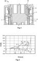
- Fig.5 shows the mating force 53 in Newton over a displacement 55 in Millimeters.
- curve 69 shows the pull out force for a connector having the improved chamfer according to the invention.
- the negative maximum 71 of this curve 69 is at 30 Newton. Thus, the pull out force is reduced in comparison with the connector without the improved chamfer.
Landscapes
- Connector Housings Or Holding Contact Members (AREA)
Abstract
Description
- The invention relates to a housing part for an electrical connector. The invention further relates to an electrical connector, a set comprising an electrical connector and a complementary connector.
- Housing parts for electrical connectors are known in the art. They can form part of a connector housing. Alternatively, in particular in the case where the housing part is formed monolithically with the remaining connector housing, the housing part may be the connector housing. An electrical connector can be used for accommodating electrical contacts. Such electrical contacts may be arranged in the opening of the housing part. In some cases, a maximum mating force may not be exceeded.
- There is a need to facilitate the mating of an electrical connector with a complementary connector.
- This need is met for the housing part in that the housing part has an opening and at least one housing wall adjacent to the opening, the housing wall having a front edge, the front edge having a chamfer extending away from the front edge at least on one side of the housing wall along a distance that varies along the front edge.
- For the electrical connector mentioned in the beginning, this need is met in that the connector comprises a housing with at least one housing part according to the invention. For the set mentioned in the beginning, the need is met in that at least one of the connectors of the set is provided with a housing part of the aforementioned type.
- Due to the varying chamfer distance, a connector which is equipped with the housing part mentioned above, can be mated with a complementary connector with reduced mating force. Thus, the housing part provides improved mating characteristics. This is of particular advantage in the case in which the complementary connector is provided with a seal, wherein the seal engages the side of the housing wall with the chamfer in a mated state. The mating force between these connectors can be reduced due to reduced friction during mating. The reason for the reduced friction is due to the fact that the complementary connector engages only the parts of the front edge having a lower distance in the beginning of a mating procedure. As the complementary connector does not engage the whole chamfer, the friction is reduced compared to a connector having a chamfer with constant distance. Only during further mating, does the complementary connector also engage parts of the front edge having the chamfer with longer distances. Another benefit is a reduced piston effect during mating.
- Since the complementary connector only engages regions of the housing wall with shorter chamfer distances in the beginning, air that is enclosed between the two connectors, in particular in the opening of the housing part, can leave the connectors in the regions having longer chamfer distances. In regions with longer distances, air can escape from air vents formed between the two connectors.
- The chamfer may extend against a plug direction of the housing part from the front edge up to the chamfer distance, wherein the chamfer distance varies along a circumferential direction of the housing part. The plug direction of the housing part is the direction, along which a connector that is provided with the housing part can be connected with a complementary connector. The circumferential direction of the housing part can be a direction along which the housing wall extends around the opening, at least in parts. Preferably, the housing wall and the front edge extend continuously around the opening. The circumferential direction preferably extends perpendicular to the plug direction.
- The at least one side of the housing wall that comprises the chamfer is preferably configured to engage a seal or another part of a complementary connector, such as a housing wall.
- In the following, further improvements of the invention are described. The additional improvements may be combined independently of each other, depending on whether a particular advantage of a particular improvement is needed in a specific application.
- According to a first advantageous improvement, the distance may vary in a wave-like manner, in particular along the front edge. In other words, an end line of the chamfer may have a waveform. Thus, a continuous chamfer with a continuous and smooth varying distance can be achieved. The end line can be the part of the chamfer having the largest distance from the front edge. A wave trough of the wave-form preferably extends away from the front edge against a plug direction of the housing part.
- The distance preferably increases towards a mid-section of the housing wall. More preferably, the distance may be longer in a mid-section of the housing wall than in a border area of the housing wall. The housing wall preferably has two border areas. The border areas may be the lateral sides of the housing wall, which are spaced apart in a width direction or in a height direction of the housing part. The width direction and the height direction are perpendicular to the plug direction. Preferably, the distance is similar at the two border areas. The mid-section may thus provide reduced friction during the beginning of a mating procedure. In addition, air can escape the opening at the mid-section with the longer distance.
- A variation of the distance along the front edge may be mirror-symmetrical. In particular, the at least one chamfer preferably extends between two opposing border areas of the housing wall in a mirror-symmetrical manner with respect to a mirror plane extending through the mid-section of the housing wall. The mirror plane may extend parallel to a plug direction and perpendicular to a circumferential direction.
- According to another advantageous improvement, the housing wall may extend at least partly around the opening, wherein the housing wall has at least one straight section and at least one further section, which is one of curved, bent and cornered. The at least one curved, bent or cornered further section is preferably arranged between two straight sections, interconnecting the two straight sections. A straight section preferably extends over 15% to 100% of a connector width or a connector height.
- Preferably, the housing part has at least two straight sections that are interconnected by at least one further section that is one of curved, bent and cornered section, wherein the chamfer extends continuously along the sections, preferably along all sections.
- The housing part may have an overall polygonal cross section formed by a plurality of straight sections, wherein each of the straight sections has a chamfer with a chamfer distance that varies along the front edge of the straight section. The straight sections are preferably interconnected by further sections, that are preferably one of curved, bent and cornered. Preferably, the chamfers of the straight sections are continuously interconnected. If curved, bent or cornered sections are arranged between straight sections, the chamfer preferably extends over the straight sections and the curved, bent or cornered sections. The distance of the chamfer may vary in at least one of the straight sections and/or in at least one of the further sections.
- The housing wall is preferably provided with a single, continuously extending chamfer that forms a closed loop along the circumferential direction.
- In an alternative to a polygonal shape, the housing part may have an overall round or ellipsoid cross section.
- According to another advantageous improvement of the housing part, contact elements are arranged in the opening, the contact elements being configured to electrically contact counter contact elements of a complementary connector.
- The opening of the housing part is configured to receive a complementary connector.
- Preferably, the side of the housing wall having the chamfer is orientated towards the opening. Thus, a complementary connector that is received in the opening may engage the chamfer at least during mating.
- Alternatively, the side of the housing wall having the chamfer may be oriented away from the opening. The housing part may, in this case, be configured to be inserted into an opening in a complementary connector.
- An inclination of the chamfer may vary along the front edge. The inclination of the chamfer is preferably measured with respect to the direction, in which the front edge faces. This direction is preferably the plug direction. The inclination may vary due to the varying distance. However, the chamfer inclination may also vary independently of the distance.
- Preferably, the chamfer has a minimum distance and a maximum distance, the maximum distance being up to 5 times the minimum distance, more preferably between 3 and 4 times the minimum distance.
- In the following, the invention and its improvements are described in greater detail using exemplary embodiments and with reference to the drawings. As described above, the various features shown in the embodiments may be used independently of each other in specific applications.
- In the following figures, elements having the same function and/or the same structure will be referenced by the same reference signs.
- In the drawings:
- Fig. 1
- shows a perspective view of an exemplary embodiment of a housing part according to the invention;
- Fig. 2
- shows a cut view of the housing part of
Fig. 1 along line II-II; - Fig. 3
- shows a cut view of the housing part of
Fig. 1 along line III-III; - Fig. 4
- shows a perspective view of an exemplary embodiment of a connector having a housing part according to the invention; and
- Fig. 5
- shows a comparison of the mating forces between different chamfers.
- In the following, an exemplary embodiment of a
housing part 1 is described with respect toFig. 1 to 3 . - The
housing part 1 is intended to be used as part of anelectrical connector 2. The housing part has anopening 3 and at least onehousing wall 5 adjacent to theopening 3. Thehousing wall 5 has afront edge 7. - Preferably, the
housing part 1 is configured to be mated with a complementary connector, wherein thefront edge 7 is orientated towards the complementary connector before mating. Thus, thefront edge 7 faces in thedirection 9, which defines aplug direction 9 of thehousing part 1. Preferably, thehousing wall 5 extends along acircumferential direction 11, which extends perpendicular to theplug direction 9. - Considering that the
plug direction 9 is parallel to alongitudinal direction 13 of thehousing part 1, thehousing part 1 can be regarded as extending also along awidth direction 15 and aheight direction 17, that extends perpendicular to thewidth direction 15. Thewidth direction 15 and theheight direction 17 both extend perpendicular to thelongitudinal direction 13. - The
opening 3 extends along thelongitudinal direction 13 into thehousing part 1 and is encircled by thehousing wall 5 along thecircumferential direction 11. - The
front edge 7 has achamfer 19. Thechamfer 19 extends away from thefront edge 7 on oneside 21 of thehousing wall 5. Thechamfer 19 extends away from thefront edge 7 against theplug direction 9. - For example, the
side 21 is the inner side of thehousing wall 5 with respect to theopening 3. In an alternative embodiment, theside 21 having thechamfer 19 may be the outer side of thehousing wall 5 and thus orientated away from theopening 3. - The
chamfer 19 extends away from thefront edge 7 along adistance 23 that is measured from thefront edge 7 towards anend line 38 of thechamfer 19. Preferably, thedistance 23 is measured along theplug direction 9. - In
Figs. 2 and 3 , two examples of thedistance 23 are shown. Thedistance 23 varies along thefront edge 7. In other words, thedistance 23 varies along thecircumferential direction 11. - Preferably, the
distance 23 of thechamfer 19 varies in a wavelike manner along thefront edge 7. Thereby, awave trough 25 preferably extends against theplug direction 9 away from thefront edge 7. - The
housing part 1 of the exemplary embodiment shows an overall polygonal form having a rectangular cross section with rounded corners. Thus, thehousing wall 5 comprises four straight sections 27, of which two straight sections 27 form two long sides 29, the long sides 29 being parallel with and spaced apart from each other. The long sides 29 extend parallel with thewidths direction 15. - Two other straight sections 27 form short sides 31 of the rectangular shape. The short sides 31 are spaced apart from and parallel with each other, and extend perpendicular to the long sides 29. The four straight sections 27 are interconnected by further sections 33. In the exemplary embodiment, the further sections 33 are curved sections 33. that form the rounded corners of the rectangular shape.
- The straight sections 27 comprise the
mid-sections 35 of thehousing wall 5 and the curved sections 33 comprise the border areas 37 of thehousing wall 5. - Preferably, the
distance 23 is similar in all four curved sections 33 and does not vary in these sections. In the straight sections 27, however, thedistance 23 preferably varies along thefront edge 7. Preferably, theend line 38 of thechamfer 19 has a wave-form in each of the four straight sections 27, wherein eachwave trough 25 extends away from thefront edge 7. - The
distance 23 is longer in the mid-section 35 of each straight section 27. In other words, thechamfer 19 preferably extends parallel with thefront edge 7 in a curved section 33 and extends with an increasing distance in a straight section 27, until amaximum distance 39 is reached in a mid-section 35 of a straight section 27. - Following the course of the
chamfer 19 further, thedistance 23 decreases until thechamfer 19 reaches the next curved section 33, where thedistance 23 is at its minimum 41, as also in the other curved sections 33. - The
chamfer 19 extends in a mirror symmetrical manner with respect to amirror plane 45 extending through themid-sections 35 of both straight sections 27. The mirror planes 45 are only indicated by dashed lines inFigs. 2 and 3 . - Due to the varying
distance 23, achamfer inclination 43 also varies along thefront edge 7. - Contact elements 47 (indicated in
Fig. 2 ) may be arranged in theopening 3 and may be configured to electrically contact counter contacts of a complementary connector (not shown here). - In the following, reference is made to
Fig. 4 that shows ahousing part 1 as part of anelectrical connector 2 in a mated state with acomplementary connector 49. Thehousing part 1 is preferably ahousing part 1 as described above with respect toFigs. 1 to 3 . Thecomplementary connector 49 and theconnector 2 may form aset 50. - The
complementary connector 49 is provided with aseal 51 that extends around a part of theconnector 49. In the mated state, theseal 51 engages thehousing wall 5 of thehousing part 1. Thereby, seal 51 abuts theside 21 of thehousing wall 5 that is provided with thechamfer 19. - The
chamfer 19 allows air to escape theopening 3 during the insertion of thecomplementary connector 49 into theopening 3. During the start of the mating procedure, thecomplementary connector 49 does not yet engage sections of thehousing wall 5 where thechamfer 19 has along distance 23. Thus, in the regions between thehousing wall 5 and theseal 51, air may escape. In addition, the friction between theseal 51 and thehousing wall 5 is reduced. - In summary, the mating force between the
connectors chamfer 19 having the varyingdistance 23. - This is also shown in
Fig.5 , which shows themating force 53 in Newton over adisplacement 55 in Millimeters. - Thereby,
curve 57 shows the insertion force of a connector having a chamfer with a constant distance along a front edge. Thiscurve 57 has a maximum 59 around 107 Newton. -
Curve 61 shows the mating force of a connector that is provided with ahousing part 1 according to the invention. Thus, the maximum 63 of the mating force is around 70 Newton. Hence, the mating force is reduced due to theimproved chamfer 19. -
Curve 65 shows the pull out force of a connector without the improved chamfer. The pull out force has its negative maximum 67 at 45 Newton. - On the other side,
curve 69 shows the pull out force for a connector having the improved chamfer according to the invention. Thenegative maximum 71 of thiscurve 69 is at 30 Newton. Thus, the pull out force is reduced in comparison with the connector without the improved chamfer. -
- 1
- Housing part
- 2
- Electrical connector
- 3
- Opening
- 5
- Housing wall
- 7
- Front edge
- 9
- Direction in which the front edge faces
- 11
- Circumferential direction
- 13
- Longitudinal direction
- 15
- Width direction
- 17
- Height direction
- 19
- Chamfer
- 21
- Side
- 23
- Distance
- 25
- Wave trough
- 27
- Straight section
- 29
- Long side
- 31
- Short side
- 33
- Further section
- 35
- Mid-section
- 37
- Border area
- 38
- End line
- 39
- Maximum distance
- 41
- Minimum distance
- 43
- Chamfer inclination
- 45
- Mirror plane
- 47
- Contact element
- 49
- Complementary connector
- 50
- Set
- 51
- Seal
- 53
- Mating force
- 55
- Displacement
- 57
- Curve
- 59
- Maximum
- 61
- Curve
- 63
- Maximum
- 65
- Curve
- 67
- Maximum
- 69
- Curve
- 71
- Maximum
Claims (13)
- Housing part (1) for an electrical connector (2), the housing part (1) having an opening (3) and at least one housing wall (5) adjacent to the opening (3), the housing wall (1) having a front edge (7), the front edge (7) having a chamfer (19) extending away from the front edge (7) at least on one side (21) of the housing wall (1) along a distance (23) that varies along the front edge (7).
- Housing part (1) according to claim 1, wherein the distance (23) varies in a wave-like manner along the front edge (7).
- Housing part (1) according to claim 1 or 2, wherein the distance (23) increases towards a mid-section (35) of the housing wall (5).
- Housing part (1) according to claim 3, wherein a variation of the distance (23) along the front edge (7) is mirror-symmetrical.
- Housing part (1) according to any one of claims 1 to 4, wherein the housing wall (1) extends at least partly around the opening (3), wherein the housing wall (5) has at least one straight section (27) and at least one further section (33), which is one of curved, bent and cornered.
- Housing part (1) according to any one of claims 1 to 5, wherein the housing part (1) has at least two straight sections (27) that are interconnected by at least one further section (33), which is one of curved, bent and cornered, wherein the chamfer (19) extends continuously along these sections (27, 33).
- Housing part (1) according to any one of claims 1 to 6, wherein the housing part (1) has an overall polygonal cross section formed by a plurality of straight sections (27), wherein each of the straight sections (27) is provided with the chamfer (19).
- Housing part (1) according to any one of claims 1 to 7, wherein contact elements (47) are arranged in the opening (3), the contact elements (47) being configured to electrically contact counter contact elements of a complementary connector (49).
- Housing part (1) according to any one of claims 1 to 8, wherein the side (21) of the housing wall (5) having the chamfer (19) is orientated towards the opening (3).
- Housing part (1) according to any one of claims 1 to 9, wherein an inclination (43) of the chamfer (19) with respect to the direction (9) in which the front edge (7) faces, varies along the front edge (7).
- Housing part (1) according to any one of claims 1 to 10, wherein the chamfer (19) has a minimum distance (41) and a maximum distance (39), the maximum distance (39) being up to 5 times the minimum distance (41).
- Electrical connector (2) having at least one housing part (1) according to any of claims 1 to 11.
- Set (50) comprising an electrical connector (2) according to claim 12 and a complementary connector (49), the complementary connector (49) having a seal (51) that is configured to engage the at least one side (21) of the housing wall (1), the at least one side (21) being provided with the chamfer (19).
Applications Claiming Priority (1)
| Application Number | Priority Date | Filing Date | Title |
|---|---|---|---|
| IN202241002555 | 2022-01-17 |
Publications (2)
| Publication Number | Publication Date |
|---|---|
| EP4213315A1 true EP4213315A1 (en) | 2023-07-19 |
| EP4213315B1 EP4213315B1 (en) | 2025-10-15 |
Family
ID=84982000
Family Applications (1)
| Application Number | Title | Priority Date | Filing Date |
|---|---|---|---|
| EP23151928.1A Active EP4213315B1 (en) | 2022-01-17 | 2023-01-17 | Housing part for an electrical connector with improved mating characteristics |
Country Status (3)
| Country | Link |
|---|---|
| US (1) | US12706411B2 (en) |
| EP (1) | EP4213315B1 (en) |
| CN (1) | CN116454670A (en) |
Families Citing this family (1)
| Publication number | Priority date | Publication date | Assignee | Title |
|---|---|---|---|---|
| CN116454670A (en) * | 2022-01-17 | 2023-07-18 | 泰科电子连接印度私有有限公司 | Housing component for an electrical connector with improved mating characteristics |
Citations (3)
| Publication number | Priority date | Publication date | Assignee | Title |
|---|---|---|---|---|
| US5637019A (en) * | 1994-11-14 | 1997-06-10 | The Panda Project | Electrical interconnect system having insulative shrouds for preventing mismating |
| US20080102683A1 (en) * | 2004-08-30 | 2008-05-01 | Fci | Electrical connector for attenuating vibrations, in particular for the injector of a motor vehicle engine |
| US10355413B2 (en) * | 2016-08-08 | 2019-07-16 | Goodrich Actuation System Sas | Electrical connection |
Family Cites Families (6)
| Publication number | Priority date | Publication date | Assignee | Title |
|---|---|---|---|---|
| US6514098B2 (en) * | 2000-12-28 | 2003-02-04 | Tyco Electronics Corporation | Electrical connector with terminal and connector position assurance devices |
| JP2014239002A (en) * | 2013-06-10 | 2014-12-18 | ヒロセ電機株式会社 | Electric connector and electric connector assembly |
| JP6243897B2 (en) * | 2015-12-15 | 2017-12-06 | 矢崎総業株式会社 | connector |
| CN207368367U (en) * | 2017-10-30 | 2018-05-15 | 浙江弗沙朗能源股份有限公司 | A kind of connection in series-parallel connector |
| DE102019112576B3 (en) * | 2019-05-14 | 2020-10-08 | Te Connectivity Germany Gmbh | Connector housing, mating connector housing and system |
| CN116454670A (en) * | 2022-01-17 | 2023-07-18 | 泰科电子连接印度私有有限公司 | Housing component for an electrical connector with improved mating characteristics |
-
2023
- 2023-01-12 CN CN202310042167.3A patent/CN116454670A/en active Pending
- 2023-01-17 US US18/155,174 patent/US12706411B2/en active Active
- 2023-01-17 EP EP23151928.1A patent/EP4213315B1/en active Active
Patent Citations (3)
| Publication number | Priority date | Publication date | Assignee | Title |
|---|---|---|---|---|
| US5637019A (en) * | 1994-11-14 | 1997-06-10 | The Panda Project | Electrical interconnect system having insulative shrouds for preventing mismating |
| US20080102683A1 (en) * | 2004-08-30 | 2008-05-01 | Fci | Electrical connector for attenuating vibrations, in particular for the injector of a motor vehicle engine |
| US10355413B2 (en) * | 2016-08-08 | 2019-07-16 | Goodrich Actuation System Sas | Electrical connection |
Also Published As
| Publication number | Publication date |
|---|---|
| CN116454670A (en) | 2023-07-18 |
| EP4213315B1 (en) | 2025-10-15 |
| US20230231337A1 (en) | 2023-07-20 |
| US12706411B2 (en) | 2026-08-11 |
Similar Documents
| Publication | Publication Date | Title |
|---|---|---|
| US5380220A (en) | Connector | |
| US5577928A (en) | Hermaphroditic electrical contact member | |
| JP3518178B2 (en) | Female terminal fitting | |
| US10193258B2 (en) | Two piece clean body female electric terminal | |
| US5911605A (en) | Universal terminal connection | |
| US4979912A (en) | Electrical connector | |
| US4007977A (en) | Electrical connector | |
| JPH1040996A (en) | Terminal fitting | |
| US3789343A (en) | Electrical connector | |
| KR960016876B1 (en) | Male electrical terminals with transient stress protection means | |
| US4368942A (en) | Keyed connector to prevent intermating with a standard connector | |
| KR950007195A (en) | Electrical connector with improved terminal latching | |
| EP4213315B1 (en) | Housing part for an electrical connector with improved mating characteristics | |
| US5860836A (en) | Contact which enables reliable discrimination of its orientation and connector using the same | |
| US5295874A (en) | Weak mating force female terminal | |
| US5030130A (en) | Connector | |
| US6585544B2 (en) | Terminal fitting | |
| US6890220B2 (en) | Electrical connector assembly | |
| US6589080B2 (en) | Terminal fitting and a connector | |
| KR100255471B1 (en) | Electrical connector having terminals with improved retention means | |
| EP0214022A2 (en) | Contact for connector | |
| KR20260012162A (en) | Female terminal, female connector and connector assembly | |
| JP7639262B2 (en) | CONNECTOR SHIELD HAVING CIRCUMFERENTIAL RETAINING ELEMENT - Patent application | |
| US6080005A (en) | Terminal fitting | |
| CN110729579A (en) | Terminal with a terminal body |
Legal Events
| Date | Code | Title | Description |
|---|---|---|---|
| PUAI | Public reference made under article 153(3) epc to a published international application that has entered the european phase |
Free format text: ORIGINAL CODE: 0009012 |
|
| STAA | Information on the status of an ep patent application or granted ep patent |
Free format text: STATUS: THE APPLICATION HAS BEEN PUBLISHED |
|
| AK | Designated contracting states |
Kind code of ref document: A1 Designated state(s): AL AT BE BG CH CY CZ DE DK EE ES FI FR GB GR HR HU IE IS IT LI LT LU LV MC ME MK MT NL NO PL PT RO RS SE SI SK SM TR |
|
| STAA | Information on the status of an ep patent application or granted ep patent |
Free format text: STATUS: REQUEST FOR EXAMINATION WAS MADE |
|
| 17P | Request for examination filed |
Effective date: 20240119 |
|
| RBV | Designated contracting states (corrected) |
Designated state(s): AL AT BE BG CH CY CZ DE DK EE ES FI FR GB GR HR HU IE IS IT LI LT LU LV MC ME MK MT NL NO PL PT RO RS SE SI SK SM TR |
|
| GRAP | Despatch of communication of intention to grant a patent |
Free format text: ORIGINAL CODE: EPIDOSNIGR1 |
|
| STAA | Information on the status of an ep patent application or granted ep patent |
Free format text: STATUS: GRANT OF PATENT IS INTENDED |
|
| RIC1 | Information provided on ipc code assigned before grant |
Ipc: H01R 13/50 20060101ALN20250528BHEP Ipc: H01R 13/629 20060101ALI20250528BHEP Ipc: H01R 13/52 20060101ALI20250528BHEP Ipc: H01R 13/631 20060101AFI20250528BHEP |
|
| INTG | Intention to grant announced |
Effective date: 20250617 |
|
| GRAS | Grant fee paid |
Free format text: ORIGINAL CODE: EPIDOSNIGR3 |
|
| GRAA | (expected) grant |
Free format text: ORIGINAL CODE: 0009210 |
|
| STAA | Information on the status of an ep patent application or granted ep patent |
Free format text: STATUS: THE PATENT HAS BEEN GRANTED |
|
| AK | Designated contracting states |
Kind code of ref document: B1 Designated state(s): AL AT BE BG CH CY CZ DE DK EE ES FI FR GB GR HR HU IE IS IT LI LT LU LV MC ME MK MT NL NO PL PT RO RS SE SI SK SM TR |
|
| REG | Reference to a national code |
Ref country code: GB Ref legal event code: FG4D Ref country code: CH Ref legal event code: F10 Free format text: ST27 STATUS EVENT CODE: U-0-0-F10-F00 (AS PROVIDED BY THE NATIONAL OFFICE) Effective date: 20251015 |
|
| REG | Reference to a national code |
Ref country code: IE Ref legal event code: FG4D |
|
| REG | Reference to a national code |
Ref country code: DE Ref legal event code: R096 Ref document number: 602023007392 Country of ref document: DE |
|
| PGFP | Annual fee paid to national office [announced via postgrant information from national office to epo] |
Ref country code: FR Payment date: 20251208 Year of fee payment: 4 |
|
| PGFP | Annual fee paid to national office [announced via postgrant information from national office to epo] |
Ref country code: SE Payment date: 20251210 Year of fee payment: 4 |
|
| REG | Reference to a national code |
Ref country code: SE Ref legal event code: TRGR |
|
| REG | Reference to a national code |
Ref country code: NL Ref legal event code: MP Effective date: 20251015 |
|
| REG | Reference to a national code |
Ref country code: AT Ref legal event code: MK05 Ref document number: 1847894 Country of ref document: AT Kind code of ref document: T Effective date: 20251015 |
|
| PG25 | Lapsed in a contracting state [announced via postgrant information from national office to epo] |
Ref country code: NL Free format text: LAPSE BECAUSE OF FAILURE TO SUBMIT A TRANSLATION OF THE DESCRIPTION OR TO PAY THE FEE WITHIN THE PRESCRIBED TIME-LIMIT Effective date: 20251015 |
|
| PG25 | Lapsed in a contracting state [announced via postgrant information from national office to epo] |
Ref country code: ES Free format text: LAPSE BECAUSE OF FAILURE TO SUBMIT A TRANSLATION OF THE DESCRIPTION OR TO PAY THE FEE WITHIN THE PRESCRIBED TIME-LIMIT Effective date: 20251015 |
|
| REG | Reference to a national code |
Ref country code: LT Ref legal event code: MG9D |
|
| PG25 | Lapsed in a contracting state [announced via postgrant information from national office to epo] |
Ref country code: NO Free format text: LAPSE BECAUSE OF FAILURE TO SUBMIT A TRANSLATION OF THE DESCRIPTION OR TO PAY THE FEE WITHIN THE PRESCRIBED TIME-LIMIT Effective date: 20260115 |
|
| PGFP | Annual fee paid to national office [announced via postgrant information from national office to epo] |
Ref country code: DE Payment date: 20251203 Year of fee payment: 4 |
|
| PG25 | Lapsed in a contracting state [announced via postgrant information from national office to epo] |
Ref country code: AT Free format text: LAPSE BECAUSE OF FAILURE TO SUBMIT A TRANSLATION OF THE DESCRIPTION OR TO PAY THE FEE WITHIN THE PRESCRIBED TIME-LIMIT Effective date: 20251015 Ref country code: FI Free format text: LAPSE BECAUSE OF FAILURE TO SUBMIT A TRANSLATION OF THE DESCRIPTION OR TO PAY THE FEE WITHIN THE PRESCRIBED TIME-LIMIT Effective date: 20251015 Ref country code: HR Free format text: LAPSE BECAUSE OF FAILURE TO SUBMIT A TRANSLATION OF THE DESCRIPTION OR TO PAY THE FEE WITHIN THE PRESCRIBED TIME-LIMIT Effective date: 20251015 |
|
| PGFP | Annual fee paid to national office [announced via postgrant information from national office to epo] |
Ref country code: IT Payment date: 20260131 Year of fee payment: 4 |
|
| PG25 | Lapsed in a contracting state [announced via postgrant information from national office to epo] |
Ref country code: RS Free format text: LAPSE BECAUSE OF FAILURE TO SUBMIT A TRANSLATION OF THE DESCRIPTION OR TO PAY THE FEE WITHIN THE PRESCRIBED TIME-LIMIT Effective date: 20260115 |
|
| PG25 | Lapsed in a contracting state [announced via postgrant information from national office to epo] |
Ref country code: IS Free format text: LAPSE BECAUSE OF FAILURE TO SUBMIT A TRANSLATION OF THE DESCRIPTION OR TO PAY THE FEE WITHIN THE PRESCRIBED TIME-LIMIT Effective date: 20260215 |
|
| PG25 | Lapsed in a contracting state [announced via postgrant information from national office to epo] |
Ref country code: PT Free format text: LAPSE BECAUSE OF FAILURE TO SUBMIT A TRANSLATION OF THE DESCRIPTION OR TO PAY THE FEE WITHIN THE PRESCRIBED TIME-LIMIT Effective date: 20260216 |
|
| PG25 | Lapsed in a contracting state [announced via postgrant information from national office to epo] |
Ref country code: PL Free format text: LAPSE BECAUSE OF FAILURE TO SUBMIT A TRANSLATION OF THE DESCRIPTION OR TO PAY THE FEE WITHIN THE PRESCRIBED TIME-LIMIT Effective date: 20251015 |
|
| PG25 | Lapsed in a contracting state [announced via postgrant information from national office to epo] |
Ref country code: LV Free format text: LAPSE BECAUSE OF FAILURE TO SUBMIT A TRANSLATION OF THE DESCRIPTION OR TO PAY THE FEE WITHIN THE PRESCRIBED TIME-LIMIT Effective date: 20251015 |
|
| PG25 | Lapsed in a contracting state [announced via postgrant information from national office to epo] |
Ref country code: BG Free format text: LAPSE BECAUSE OF FAILURE TO SUBMIT A TRANSLATION OF THE DESCRIPTION OR TO PAY THE FEE WITHIN THE PRESCRIBED TIME-LIMIT Effective date: 20251015 |
|
| PG25 | Lapsed in a contracting state [announced via postgrant information from national office to epo] |
Ref country code: LT Free format text: LAPSE BECAUSE OF FAILURE TO SUBMIT A TRANSLATION OF THE DESCRIPTION OR TO PAY THE FEE WITHIN THE PRESCRIBED TIME-LIMIT Effective date: 20251015 |
|
| PG25 | Lapsed in a contracting state [announced via postgrant information from national office to epo] |
Ref country code: SM Free format text: LAPSE BECAUSE OF FAILURE TO SUBMIT A TRANSLATION OF THE DESCRIPTION OR TO PAY THE FEE WITHIN THE PRESCRIBED TIME-LIMIT Effective date: 20251015 |
|
| PG25 | Lapsed in a contracting state [announced via postgrant information from national office to epo] |
Ref country code: DK Free format text: LAPSE BECAUSE OF FAILURE TO SUBMIT A TRANSLATION OF THE DESCRIPTION OR TO PAY THE FEE WITHIN THE PRESCRIBED TIME-LIMIT Effective date: 20251015 |
|
| PG25 | Lapsed in a contracting state [announced via postgrant information from national office to epo] |
Ref country code: EE Free format text: LAPSE BECAUSE OF FAILURE TO SUBMIT A TRANSLATION OF THE DESCRIPTION OR TO PAY THE FEE WITHIN THE PRESCRIBED TIME-LIMIT Effective date: 20251015 |
|
| PG25 | Lapsed in a contracting state [announced via postgrant information from national office to epo] |
Ref country code: CZ Free format text: LAPSE BECAUSE OF FAILURE TO SUBMIT A TRANSLATION OF THE DESCRIPTION OR TO PAY THE FEE WITHIN THE PRESCRIBED TIME-LIMIT Effective date: 20251015 |
|
| PG25 | Lapsed in a contracting state [announced via postgrant information from national office to epo] |
Ref country code: SK Free format text: LAPSE BECAUSE OF FAILURE TO SUBMIT A TRANSLATION OF THE DESCRIPTION OR TO PAY THE FEE WITHIN THE PRESCRIBED TIME-LIMIT Effective date: 20251015 |