EP4213303A1 - Antenna - Google Patents
Antenna Download PDFInfo
- Publication number
- EP4213303A1 EP4213303A1 EP23151139.5A EP23151139A EP4213303A1 EP 4213303 A1 EP4213303 A1 EP 4213303A1 EP 23151139 A EP23151139 A EP 23151139A EP 4213303 A1 EP4213303 A1 EP 4213303A1
- Authority
- EP
- European Patent Office
- Prior art keywords
- antenna
- feed line
- radio frequency
- frequency signals
- switch
- Prior art date
- Legal status (The legal status is an assumption and is not a legal conclusion. Google has not performed a legal analysis and makes no representation as to the accuracy of the status listed.)
- Pending
Links
Images






Classifications
-
- H—ELECTRICITY
- H01—ELECTRIC ELEMENTS
- H01Q—ANTENNAS, i.e. RADIO AERIALS
- H01Q5/00—Arrangements for simultaneous operation of antennas on two or more different wavebands, e.g. dual-band or multi-band arrangements
- H01Q5/40—Imbricated or interleaved structures; Combined or electromagnetically coupled arrangements, e.g. comprising two or more non-connected fed radiating elements
- H01Q5/48—Combinations of two or more dipole type antennas
-
- H—ELECTRICITY
- H01—ELECTRIC ELEMENTS
- H01Q—ANTENNAS, i.e. RADIO AERIALS
- H01Q21/00—Antenna arrays or systems
- H01Q21/24—Combinations of antenna units polarised in different directions for transmitting or receiving circularly and elliptically polarised waves or waves linearly polarised in any direction
- H01Q21/26—Turnstile or like antennas comprising arrangements of three or more elongated elements disposed radially and symmetrically in a horizontal plane about a common centre
-
- H—ELECTRICITY
- H01—ELECTRIC ELEMENTS
- H01Q—ANTENNAS, i.e. RADIO AERIALS
- H01Q21/00—Antenna arrays or systems
- H01Q21/06—Arrays of individually energised antenna units similarly polarised and spaced apart
- H01Q21/061—Two dimensional planar arrays
- H01Q21/062—Two dimensional planar arrays using dipole aerials
-
- H—ELECTRICITY
- H01—ELECTRIC ELEMENTS
- H01Q—ANTENNAS, i.e. RADIO AERIALS
- H01Q25/00—Antennas or antenna systems providing at least two radiating patterns
-
- H—ELECTRICITY
- H01—ELECTRIC ELEMENTS
- H01Q—ANTENNAS, i.e. RADIO AERIALS
- H01Q3/00—Arrangements for changing or varying the orientation or the shape of the directional pattern of the waves radiated from an antenna or antenna system
- H01Q3/24—Arrangements for changing or varying the orientation or the shape of the directional pattern of the waves radiated from an antenna or antenna system varying the orientation by switching energy from one active radiating element to another, e.g. for beam switching
- H01Q3/247—Arrangements for changing or varying the orientation or the shape of the directional pattern of the waves radiated from an antenna or antenna system varying the orientation by switching energy from one active radiating element to another, e.g. for beam switching by switching different parts of a primary active element
-
- H—ELECTRICITY
- H01—ELECTRIC ELEMENTS
- H01Q—ANTENNAS, i.e. RADIO AERIALS
- H01Q9/00—Electrically-short antennas having dimensions not more than twice the operating wavelength and consisting of conductive active radiating elements
- H01Q9/04—Resonant antennas
- H01Q9/0407—Substantially flat resonant element parallel to ground plane, e.g. patch antenna
- H01Q9/0421—Substantially flat resonant element parallel to ground plane, e.g. patch antenna with a shorting wall or a shorting pin at one end of the element
-
- H—ELECTRICITY
- H01—ELECTRIC ELEMENTS
- H01Q—ANTENNAS, i.e. RADIO AERIALS
- H01Q9/00—Electrically-short antennas having dimensions not more than twice the operating wavelength and consisting of conductive active radiating elements
- H01Q9/04—Resonant antennas
- H01Q9/16—Resonant antennas with feed intermediate between the extremities of the antenna, e.g. centre-fed dipole
- H01Q9/28—Conical, cylindrical, cage, strip, gauze, or like elements having an extended radiating surface; Elements comprising two conical surfaces having collinear axes and adjacent apices and fed by two-conductor transmission lines
- H01Q9/285—Planar dipole
Definitions
- the present invention relates to an antenna device, and, in particular, to a wide coverage shared aperture antenna.
- An antenna device is defined by the independent claim.
- An embodiment of the present invention provides an antenna device.
- the antenna device includes a first antenna and a second antenna.
- the first antenna receives or transmits first radio frequency signals to a first direction.
- the second antenna receives or transmits second radio frequency signals to a second direction.
- the first direction is different from the second direction.
- Radiators of the first antenna and the second antenna are shared.
- the direction-angle difference between the first direction and the second direction is larger than 30 degrees.
- the frequency of the first radio frequency signals is the same as that of the second radio frequency signals; or the frequency of the first radio frequency signals is different from that of the second radio frequency signals.
- the first antenna is a dipole antenna
- the second antenna is a planar inverted-F (PIFA) liked antenna.
- the first antenna includes a first feed line.
- the second antenna includes a second feed line.
- the first feed line electrically couples the first radio frequency signals to the radiators of the first antenna.
- the second feed line electrically connects or couples the second radio frequency signals to the radiators of the second antenna.
- the second antenna includes a tuning circuit.
- the tuning circuit is electrically connected to the second feed line or to the radiators of the second antenna.
- the first antenna includes a tuning circuit.
- the tuning circuit is electrically connected to the first feed line or to the radiators of the first antenna.
- the tuning circuit includes a phase shifter and a switch.
- the phase shifter delays the phase of the second radio frequency signals.
- the switch shorts the second feed line to a ground, or opens the second feed line.
- the phase shifter includes a variable capacitor and a transmission line.
- the variable capacitor is electrically connected in parallel between the second feed line and the ground, and it changes the impedance of the second feed line.
- the transmission line is electrically connected to the second feed line in series, and it delays the phase of the second radio frequency signals.
- the radiators of the first antenna include a first portion and a second portion.
- the first feed line is disposed between the first portion and the second portion.
- the first portion and the second portion form the shape of a pair of gull wings.
- the radiators of the second antenna include the first portion of the radiators of the first antenna, the second feed line, and a ground.
- the switch when the first antenna receives or transmits the first radio frequency signals to the first direction, the switch opens the second feed line. When the second antenna receives or transmits the second radio frequency signals to the second direction, the switch shorts the second feed line to the ground.
- the antenna device further includes a third antenna.
- the third antenna receives or transmits third radio frequency signals to a third direction.
- the third direction and the second direction are in opposite directions.
- the radiators of the first antenna and the third antenna are shared.
- the third antenna includes a third feed line.
- the third feed line is electrically connects or couples the third radio frequency signals to the radiators of the third antenna.
- the third antenna is a planar inverted-F (PIFA) antenna.
- PIFA planar inverted-F
- the polarization direction of the first radio frequency signals is the same as the second direction or the opposite direction of the second direction.
- the polarization direction of the second frequency signals is the same as the first direction or the opposite direction of the first direction.
- the antenna device further includes a fourth antenna.
- the fourth antenna receives or transmits fourth radio frequency signals to the first direction.
- the polarization direction of the fourth radio frequency signals is a fourth direction.
- the fourth direction is orthogonal to the second direction.
- the fourth antenna includes a fourth feed line.
- the fourth feed line is electrically couples the fourth radio frequency signals to the radiators of the fourth antenna.
- the fourth antenna is a dipole antenna.
- the radiators of the fourth antenna include a third portion and a fourth portion.
- the fourth feed line is disposed between the third portion and the fourth portion.
- the third portion and the fourth portion form the shape of a pair of gull wings.
- the corresponding component such as layer or area
- it may be directly on this other component, or other components may exist between them.
- the component when the component is referred to as being “directly on another component (or the variant thereof)", there is no component between them.
- the corresponding component and the other component when the corresponding component is referred to as being “on another component”, the corresponding component and the other component have a disposition relationship along a top-view/vertical direction, the corresponding component may be below or above the other component, and the disposition relationship along the top-view/vertical direction is determined by the orientation of the device.
- the electrical connection or coupling described in this disclosure may refer to direct connection or indirect connection.
- direct connection the endpoints of the components on the two circuits are directly connected or connected to each other by a conductor line segment, while in the case of indirect connection, there are switches, diodes, capacitors, inductors, resistors, other suitable components, or a combination of the above components between the endpoints of the components on the two circuits, but the intermediate component is not limited thereto.
- Fig. 1A is a schematic diagram of an antenna device in accordance with some embodiments of the present invention.
- the antenna device includes a first antenna, a second antenna, and a third antenna.
- the first antenna includes a radiator 100, a radiator 102, and a feed line 106.
- the first antenna receives or transmits first radio frequency signals to a first direction (e.g., the Z direction).
- the feed line 106 electrically couples the first radio frequency signals to the radiators 100 and 102 of the first antenna.
- the feed line 106 passes through a ground GND along the Z direction and is disposed between the radiators 100 and 102, and the radiators 100 and 102 form the shape of a pair of gull wings, but the present invention is not limited thereto.
- the polarization direction of the first radio frequency signals transmitted from the first antenna is the same as the X direction or the -X direction.
- the first antenna is a dipole antenna, but the present invention is not limited thereto.
- the second antenna includes the radiator 100, the ground GND, and a feed line 104.
- the radiator 100 is shared by the first antenna and the second antenna.
- the second antenna receives or transmits second radio frequency signals to a second direction (e.g., the -X direction).
- the feed line 104 electrically couples the second radio frequency signals to the radiator 100 of the second antenna.
- the feed line 104 passes through the ground GND along the Z direction and is covered by the radiator 100 in view of the -Z direction.
- the feed line 104 and the radiator 100 form the shape of an inverted F, but the present invention is not limited thereto.
- the polarization direction of the second radio frequency signals transmitted from the second antenna is the same as the Z direction or the -Z direction.
- the second antenna is a planar inverted-F (PIFA) liked antenna, but the present invention is not limited thereto.
- the third antenna includes the radiator 102, the ground GND, and a feed line 108.
- the radiator 102 is shared by the first antenna and the third antenna.
- the third antenna receives or transmits third radio frequency signals to a third direction (e.g., the X direction).
- the feed line 108 electrically couples the third radio frequency signals to the radiator 102 of the third antenna.
- the feed line 108 passes through the ground GND along the Z direction and is covered by the radiator 102 in view of the -Z direction.
- the feed line 108 and the radiator 102 form the shape of an inverted F, but the present invention is not limited thereto.
- the polarization direction of the third radio frequency signals transmitted from the third antenna is the same as the Z direction or the -Z direction.
- the third antenna is a PIFA antenna, but the present invention is not limited thereto.
- the frequency of the first radio frequency signals is the same or different from that of the second radio frequency signals.
- the frequency of the second radio frequency signals is the same or different from that of the third radio frequency signals.
- the frequency of the third radio frequency signals is the same or different from that of the first radio frequency signals.
- Fig. 1B is a schematic diagram of an antenna device in accordance with some embodiments of the present invention.
- the difference between the antenna device in Fig. 1B and the antenna device Fig. 1A is that the feed line 104 of the second antenna in Fig. 1B electrically connects the second radio frequency signals to the radiator 100 of the second antenna, and the feed line 108 of the third antenna in Fig. 1B electrically connects the third radio frequency signals to the radiator 102 of the third antenna.
- the feed line 104 of the second antenna electrically connects to the horizontal (e.g., the X direction) portion of the radiator 100.
- the feed line 108 of the third antenna electrically connects to the vertical (e.g. the Z direction) portion of the radiator 102.
- Fig. 1C is a schematic diagram of an antenna device in accordance with some embodiments of the present invention.
- the difference between the antenna device in Fig. 1C and the antenna device Fig. 1A is that the feed line 104 of the second antenna in Fig. 1C electrically connects the second radio frequency signals to the radiator 100 of the second antenna, and the feed line 108 of the third antenna in Fig. 1C electrically connects the third radio frequency signals to the radiator 102 of the third antenna.
- the feed line 104 of the second antenna electrically connects to the vertical (e.g., the Z direction) portion of the radiator 100.
- the feed line 108 of the third antenna electrically connects to the horizontal (e.g. the X direction) portion of the radiator 102.
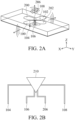
- Fig. 2A is a stereogram of an antenna device in accordance with some embodiments of the present invention.
- the antenna device includes a the first antenna in Fig. 1B , the second antenna in Fig. 1B , the third antenna in Fig. 1B , and a fourth antenna.
- the fourth antenna receives or transmits fourth radio frequency signals to the first direction (e.g., the Z direction).
- the fourth antenna includes a radiator 200, a radiator 202, and a feed line 206.
- the feed line 206 electrically couples the fourth radio frequency signals to the radiators 200 and 202 of the fourth antenna.
- the feed line 206 passes through the ground GND along the Z direction and is disposed between the radiators 200 and 202, and the radiators 200 and 202 form the shape of a pair of gull wings, but the present invention is not limited thereto. Both feed lines 106 and 206 are surrounded by the radiators 100, 102, 200, and 202, but the present invention is not limited thereto.
- the polarization direction of the fourth radio frequency signals transmitted from the fourth antenna is the same as the Y direction or the -Y direction in Fig. 2A .
- the polarization direction of the first radio frequency signals transmitted from the first antenna is the same as the X direction or the -X direction in Fig. 2A .
- the polarization direction of the fourth radio frequency signals is orthogonal to that of the first radio frequency signals.
- the fourth antenna is a dipole antenna, but the present invention is not limited thereto.
- the angle difference between the first direction (e.g., the Z direction in Fig. 2A ) and the second direction (e.g., the X direction in Fig. 2A ) is larger than 30 degrees.
- the angle difference between the Z direction in Fig. 2A and the X direction in Fig. 2A is 90 degrees, but the present invention is not limited thereto.
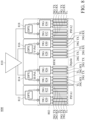
- Fig. 2B is a block diagram of the antenna device in Fig. 2A in accordance with some embodiments of the present invention.
- the antenna device 210 includes the first antenna, the second antenna, the third antenna, and the fourth antenna in Fig. 2A .
- the first antenna includes the feed line 106 to receive or transmit the first radio frequency signals.
- the second antenna includes the feed line 104 to receive or transmit the second radio frequency signals.
- the third antenna includes the feed line 108 to receive or transmit the third radio frequency signals.
- the fourth antenna includes the feed line 206 to receive or transmit the fourth radio frequency signals.
- the first radio frequency signals are radiated by the radiators 100 and 102 of the first antenna.
- the second radio frequency signals are radiated by the radiator 100 and the feed line 104 of the second antenna, and the ground GND.
- the third radio frequency signals are radiated by the radiator 102 and the feed line 108 of the third antenna, and the ground GND.
- the fourth radio frequency signals are radiated by the radiators 200 and 202 of the fourth antenna.
- the frequency of the fourth radio frequency signals is the same or different from that of the first radio frequency signals.
- Fig. 3A is a schematic diagram of an antenna device in accordance with some embodiments of the present invention.
- the difference between the antenna device in Fig. 3A and the antenna device in Fig. 1B is that the second antenna further includes a tuning circuit 300 electrically connected in series on the feed line 104, and the third antenna further includes a tuning circuit 302 electrically connected in series on the feed line 108.
- the tuning circuit 300 is the same as the tuning circuit 302.
- Fig. 3B is a schematic diagram of the tuning circuit 300 in Fig. 3A in accordance with some embodiments of the present invention.
- the tuning circuit 300 includes a phase shifter 310 and a switch 312.
- the tuning circuit 302 includes a phase shifter 320 and a switch 322.
- the phase shifter 310 delays the phase of the second radio frequency signals.
- the switch 312 shorts the feed line 104 to the ground GND or opens the second feed line 104 according which antenna is currently under work.
- the phase shifter 320 delays the phase of the third radio frequency signals.
- the switch 322 shorts the feed line 108 to the ground GND or opens the second feed line 108 according which antenna is currently under work. For example, when the first antenna including the radiators 100 and 102, and the feed line 106 is under work, the first antenna receives or transmits the first radio frequency signals to the first direction (e.g., the Z direction), the switch 312 shorts the feed line 104 to the ground GND and the switch 322 shorts the feed line 108 to the ground GND.
- the first direction e.g., the Z direction
- the second antenna when the second antenna including the radiator 100, the feed line 104, and the ground GND is currently under work, the second antenna receives or transmits the second radio frequency signals to the second direction (e.g., the -X direction), the switch 312 opens the feed line 104 and the switch 322 shorts the feed line 108 to the ground GND.
- the third antenna when the third antenna including the radiator 102, the feed line 108, and the ground is currently under work, the third antenna receives or transmits the third radio frequency signals to the third direction (e.g., the X direction), the switch 322 opens the feed line 108 and the switch 312 shorts the feed line 104 to the ground GND.
- Fig. 3C is a detail schematic diagram of the tuning circuit 300 in Fig. 3A in accordance with some embodiments of the present invention.
- the phase shifter 310 in Fig. 3B includes a variable capacitor 314 and a delay line 316.
- the variable capacitor 314 is electrically connected in parallel between the feed line 104 and the ground GND, and changes the impedance of the feed line 104.
- the delay line 316 is electrically connected to the feed line 104 in series, and delays the phase of the second radio frequency signals.
- the switch 312 is electrically connected in parallel between the feed line 104 and the ground GND.
- the phase shifter 320 in Fig. 3B includes a variable capacitor (not shown) and a delay line (not shown).
- the variable capacitor in the phase shifter 320 is electrically connected in parallel between the feed line 108 and the ground GND, and changes the impedance of the feed line 108.
- the delay line in the phase shifter 320 is electrically connected to the feed line 108 in series, and delays the phase of the third radio frequency signals.
- the switch 322 is electrically connected in parallel between the feed line 108 and the ground GND.
- the impedance of the feed line 108 can be match to a predetermined value (for example, 50 ohms).
- Fig. 4A is a schematic diagram of an antenna device in accordance with some embodiments of the present invention.
- the difference between the antenna device in Fig. 4A and the antenna device in Fig. 2A is that the antenna device in Fig. 4A further includes a fifth antenna including the radiator 200, a feed line 400, and the ground GND, and a sixth antenna including the radiator 202, a feed line 402, and the ground.
- the fifth antenna receives or transmits fifth radio frequency signals to the -Y direction.
- the feed line 400 electrically connects the fifth radio frequency signals to the radiator 200.
- the feed line 400 passes through the ground GND along the Z direction and is covered by the radiator 200 in view of the -Z direction.
- the radiator 200 is shared by the fourth antenna and the fifth antenna.
- the polarization direction of the fifth radio frequency signals is the same as the Z direction or the -Z direction.
- the sixth antenna receives or transmits sixth radio frequency signals to the Y direction.
- the feed line 402 electrically connects the sixth radio frequency signals to the radiator 202.
- the feed line 402 passes through the ground GND along the Z direction and is covered by the radiator 202 in view of the -Z direction.
- the radiator 202 is shared by the fourth antenna and the sixth antenna.
- the polarization direction of the sixth radio frequency signals is the same as the Z direction or the -Z direction.
- the fifth antenna and the sixth antenna are PIFA antenna, but the present invention is not limited thereto.
- Fig. 4B is a block diagram of the antenna device in Fig. 4A in accordance with some embodiments of the present invention.
- the antenna device 410 includes the first antenna, the second antenna, the third antenna, the fourth antenna, the fifth antenna, and the sixth antenna in Fig. 4A .
- the first antenna includes the feed line 106 to receive or transmit the first radio frequency signals.
- the second antenna includes the feed line 104 to receive or transmit the second radio frequency signals.
- the third antenna includes the feed line 108 to receive or transmit the third radio frequency signals.
- the fourth antenna includes the feed line 206 to receive or transmit the fourth radio frequency signals.
- the fifth antenna includes the feed line 400 to receive or transmit the fifth radio frequency signals.
- the sixth antenna includes the feed line 402 to receive or transmit the sixth radio frequency signals.
- the first radio frequency signals are radiated by the radiators 100 and 102 of the first antenna.
- the second radio frequency signals are radiated by the radiator 100 and the feed line 104 of the second antenna, and the ground GND.
- the third radio frequency signals are radiated by the radiator 102 and the feed line 108 of the third antenna, and the ground GND.
- the fourth radio frequency signals are radiated by the radiators 200 and 202 of the fourth antenna.
- the fifth radio frequency signals are radiated by the radiator 200 and the feed line 400 of the fifth antenna, and the ground GND.
- the sixth radio frequency signals are radiated by the radiator 202 and the feed line 402 of the sixth antenna, and the ground GND.
- Fig. 5A is a schematic diagram of an antenna device in accordance with some embodiments of the present invention.
- the difference between the antenna device in Fig. 5A and the antenna device in Fig. 4A is that the antenna device in Fig. 5A is obtained by clockwise rotating the antenna device in Fig. 4A about 45 degrees. That is, the first antenna including the radiators 100 and 102, and the feed line 106 receives or transmits the first radio frequency signals to the Z direction.
- the polarization direction of the first radio frequency signals is equal to the direction between the X direction and the -Y direction.
- the polarization direction of the first radio frequency signals is equal to the direction with the direction-angle difference of -45 degrees from the X direction, or the direction with the direction-angle difference of 135 degrees from the X direction.
- the second antenna including the radiator 100, the feed line 104, and the ground GND receives or transmits the second radio frequency signals to the direction between the X direction and the -Y direction.
- the direction between the X direction and the -Y direction may be the direction with the direction-angle difference of -45 degrees from the X direction.
- the polarization direction of the second radio frequency signals is equal to the Z direction or the -Z direction.
- the third antenna including the radiator 102, the feed line 108, and the ground GND receives or transmits the third radio frequency signals to the direction between the -X direction and the Y direction.
- the direction between the -X direction and the Y direction may be the direction with the direction-angle difference of 135 degrees from the X direction.
- the polarization direction of the third radio frequency signals is equal to the Z direction or the -Z direction.
- the fourth antenna including the radiators 200 and 202, and the feed line 206 receives or transmits the fourth radio frequency signals to the Z direction.
- the polarization direction of the fourth radio frequency signals is equal to the direction between the X direction and the Y direction.
- the polarization direction of the fourth radio frequency signals is equal to the direction with the direction-angle difference of 45 degrees from the X direction.
- the fifth antenna including the radiator 200, the feed line 400, and the ground GND receives or transmits the fifth radio frequency signals to the direction between the -X direction and the -Y direction.
- the direction between the -X direction and the -Y direction may be the direction with the direction-angle difference of - 135 degrees from the X direction.
- the polarization direction of the fifth radio frequency signals is equal to the Z direction or the -Z direction.
- the sixth antenna including radiator 202, the feed line 402, and the ground GND receives or transmits the sixth radio frequency signals to the direction between the X direction and the Y direction.
- the direction between the X direction and the Y direction may be the direction with the direction-angle difference of 45 degrees from the X direction.
- the polarization direction of the sixth radio frequency signals is equal to the Z direction or the -Z direction.
- Fig. 5B is a block diagram of the antenna device in Fig. 5A in accordance with some embodiments of the present invention.
- the antenna device 510 includes the first antenna, the second antenna, the third antenna, the fourth antenna, the fifth antenna, and the sixth antenna in Fig. 5A .
- the first antenna includes the feed line 106 to receive or transmit the first radio frequency signals.
- the second antenna includes the feed line 104 to receive or transmit the second radio frequency signals.
- the third antenna includes the feed line 108 to receive or transmit the third radio frequency signals.
- the fourth antenna includes the feed line 206 to receive or transmit the fourth radio frequency signals.
- the fifth antenna includes the feed line 400 to receive or transmit the fifth radio frequency signals.
- the sixth antenna includes the feed line 402 to receive or transmit the sixth radio frequency signals.
- the first radio frequency signals are radiated by the radiators 100 and 102 of the first antenna.
- the second radio frequency signals are radiated by the radiator 100 and the feed line 104 of the second antenna, and the ground GND.
- the third radio frequency signals are radiated by the radiator 102 and the feed line 108 of the third antenna, and the ground GND.
- the fourth radio frequency signals are radiated by the radiators 200 and 202 of the fourth antenna.
- the fifth radio frequency signals are radiated by the radiator 200 and the feed line 400 of the fifth antenna, and the ground GND.
- the sixth radio frequency signals are radiated by the radiator 202 and the feed line 402 of the sixth antenna, and the ground GND.
- Fig. 6A is a schematic diagram of an antenna device in accordance with some embodiments of the present invention.
- the difference between the antenna device 510 in Fig. 6A and the antenna device in Fig. 5A is that the second radio frequency signals transmitted from the second antenna including the radiator 100, the feed line 104, and the ground GND are combined with the sixth radio frequency signals transmitted from the sixth antenna including the radiator 202, the feed line 402, and the ground GND.
- the fifth radio frequency signals transmitted from the fifth antenna including the radiator 200, the feed line 400, and the ground GND are combined with the third radio frequency signals transmitted from the third antenna including the radiator 102, the feed line 108, and the ground GND.
- the second radio frequency signals are propagated to the direction 610
- the sixth radio frequency signals are propagated to the direction 620.
- the first subcomponents of the second radio frequency signals propagated to the direction 612 are combined with the first subcomponents of the sixth radio frequency signals propagated to the direction 622.
- the direction 612 is the same as the direction 622.
- the directions 612 and 622 are the same as the X direction.
- the second subcomponents of the second radio frequency signals propagated to the direction 614 and the second subcomponents of the sixth radio frequency signals propagated to the direction 624 are cancelled by each other.
- Fig. 6B is a schematic diagram of an antenna array including the antenna device in Fig. 6A in accordance with some embodiments of the present invention.
- the antenna array includes four antenna devices 510 in Fig. 6A , but the present invention is not limited thereto.
- the antenna array in Fig. 6B may transmit the combined radio frequency signals to the X direction (e.g., the directions 612 and 622) with higher gain and narrow beam width due to physical characteristics of the antenna array.
- Fig. 6C is a block diagram of the antenna device in Fig. 6A in accordance with some embodiments of the present invention. As shown in Fig.
- the antenna device further includes a combiner 600 and a combiner 602.
- the combiner 600 combines the feed line 104 of the second antenna and the feed line 402 of the sixth antenna to obtain a combined feed line 630.
- the combiner 602 combines the feed line 108 of the third antenna and the feed line 400 of the fifth antenna to obtain a combined feed line 640.
- the combined feed line 630 controls the antenna array to receive or transmit the combined radio frequency signals to the X direction.
- the combined feed line 640 controls the antenna array to receive or transmit the combined radio frequency signals to the -X direction.
- the feed lines 106 and 206 controls the antenna array to receive or transmit the radio frequency signals to the Z direction with different polarization directions, respectively.
- Fig. 7 is a schematic diagram of an antenna control system 700 including the antenna device 210 in Fig. 2B in accordance with some embodiments of the present invention.
- the feed line 104 of the second antenna in the antenna device 210 is electrically connected to an SPDT switch 702.
- the first output end of the SPDT switch 702 is electrically connected to an RF terminal (T/R) 720.
- the second output end of the SPDT switch 702 is electrically connected to a load 710.
- the feed line 106 of the first antenna in the antenna device 210 is electrically connected to an SPDT switch 704.
- the first output end of the SPDT switch 704 is electrically connected to a load 712.
- the second output end of the SPDT switch 704 is electrically connected to an RF terminal 722.
- the feed line 206 of the fourth antenna in the antenna device 210 is electrically connected to an SPDT switch 706.
- the first output end of the SPDT switch 706 is electrically connected to an RF terminal 724.
- the second output end of the SPDT switch 706 is electrically connected to a load 714.
- the feed line 108 of the third antenna in the antenna device 210 is electrically connected to an SPDT switch 708.
- the first output end of the SPDT switch 708 is electrically connected to a load 716.
- the second output end of the SPDT switch 708 is electrically connected to an RF terminal 726.
- the loads 710, 712, 714, and 716 may be, for example, impedance tuners, open traces, short traces, tuning capacitors, tuning inductors, and phase shifters, but the present invention is not limited thereto.
- the RF terminals 720, 722, 724, and 726 are RF function ports of an RFIC (for example, a transceiver), but the present invention is not limited thereto.
- the feed line 106 is electrically connected to the RF terminal 722 through the SPDT switch 704, and the feed line 206 is electrically connected to the RF terminal 724 through the SPDT switch 706.
- the second antenna and the third antenna in the antenna device 210 are not under work, the feed line 104 is electrically connected to the load 710 through the SPDT switch 702, and the feed line 108 is electrically connected to the load 716 through the SPDT switch 708.
- the feed line 104 is electrically connected to the RF terminal 720 through the SPDT switch 702, and the feed line 108 is electrically connected to the RF terminal 726 through the SPDT switch 708.
- the first antenna and the fourth antenna in the antenna device 210 are not under work, the feed line 106 is electrically connected to the load 712 through the SPDT switch 704, and the feed line 206 is electrically connected to the load 714 through the SPDT switch 706.
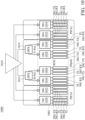
- Fig. 8 is a schematic diagram of an antenna control system 800 in accordance with some embodiments of the present invention.
- the antenna control system 800 includes an antenna device 810, a diplexer (DPX) 812, a diplexer 814, a diplexer 816, a diplexer 818, and an RFIC 802.
- the diplexer 812 is used for a first PIFA antenna (PIFA1)
- the diplexer 814 is used for a first dipole antenna (Dipole)
- the diplexer 816 is used for a second dipole antenna (Dipole)
- the diplexer 818 is used for a second PIFA antenna (PIFA2).
- the RFIC 802 includes switches 820, 822, 824, 826, 828, 830, 832, and 834.
- the switches 820, 824, 830 834 are used to control the receiving (the block 39G RX) or transmitting (the block 39G TX) of high band RF signals (e.g., the 39GHz RF signals) or to connect the respective diplexers to the tuning load TL.
- the switches 822, 826, 828, and 832 are used to control the receiving (the block 28G RX) or transmitting (the block 28G TX) of low band RF signals(e.g., the 28GHz RF signals) or to connect the respective diplexers to the tuning load TL.
- the antenna device 810 includes the first PIFA antenna (the second antenna in Fig. 2A ), the first dipole antenna (the first antenna in Fig. 2A ), the second dipole antenna (the fourth antenna in Fig. 2A ), and the second PIFA antenna (the third antenna in Fig. 2A ).
- the feed line of the first PIFA antenna is electrically connected to the diplexer 812.
- the feed line of the first dipole antenna is electrically connected to the diplexer 814.
- the feed line of the second dipole antenna is electrically connected to the diplexer 816.
- the feed line of the second PIFA antenna is electrically connected to the diplexer 818.
- the diplexer 814 electrically connects the feed line of the first dipole antenna to the switch 824, and the switch 824 enables the transmitting of the high band RF signals (39G TX).
- the diplexer 816 electrically connects the feed line of the second dipole antenna to the switch 830, and the switch 830 also enables the transmitting of the high band RF signals (39G TX).
- the diplexer 812 electrically connects the feed line of the first PIFA antenna to the switch 820, and the switch 820 electrically connects the tuning load TL to the diplexer 812.
- the diplexer 818 electrically connects the feed line of the second PIFA antenna to the switch 834, and the switch 834 electrically connects the tuning load TL to the diplexer 818.
- the diplexer 812 electrically connects the feed line of the first PIFA antenna to the switch 822, and the switch 822 enables the receiving of the low band RF signals (28G RX).
- the diplexer 818 electrically connects the feed line of the second PIFA antenna to the switch 832, and the switch 832 electrically connects the tuning load TL to the diplexer 812.
- the diplexer 814 electrically connects the feed line of the first dipole antenna to the r the switch 826, and the switch 824 electrically connects the tuning load TL to the diplexer 814.
- the diplexer 816 electrically connects the feed line of the second dipole antenna to the switch 828, and the switch 828 electrically connects the tuning load TL to the diplexer 816.
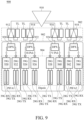
- Fig. 9 is a schematic diagram of an antenna control system 900 in accordance with some embodiments of the present invention.
- the antenna control system 900 includes an antenna device 910, an external IC 902 nearby the antenna device 910, diplexers (DPX) 920, 922, 924, and 926, and an RFIC 904.
- the antenna device 910 includes a first PIFA antenna (PIFA1), a second PIFA antenna (PIFA2), a first dipole antenna (Dipole), and a second dipole antenna (Dipole).
- the external IC 902 includes switches 912, 914, 916, and 918, and tuning loads TL.
- the input end of the switch 912 electrically connects to the feed line of the first PIFA antenna.
- the first output end of the switch 912 electrically connects to the diplexer 920.
- the second output end of the switch 912 electrically connects to the tuning load TL.
- the input end of the switch 914 electrically connects to the feed line of the first dipole antenna.
- the first output end of the switch 914 electrically connects to the tuning load TL.
- the second output end of the switch 914 electrically connects to the diplexer 922.
- the input end of the switch 916 electrically connects to the feed line of the second dipole antenna.
- the first output end of the switch 916 electrically connects to the diplexer 924.
- the second output end of the switch 916 electrically connects to the tuning load TL.
- the input end of the switch 918 electrically connects to the feed line of the second PIFA antenna.
- the first output end of the switch 918 electrically connects to the tuning load TL.
- the second output end of the switch 918 electrically connects to the diplexer 926.
- the tuning load TL may be, for example, impedance tuners, open traces, short traces, tuning capacitors, tuning inductors, and phase shifters, but the present invention is not limited thereto.
- the RFIC 904 includes switches 930, 932, 934, 936, 938, 940, 942, and 944.
- the switches 930, 934, 940, and 944 are used to control the receiving (the block 39G RX) or transmitting (the block 39G TX) of high band RF signals (e.g., the 39GHz RF signals).
- the switches 932, 936, 938, and 942 are used to control the receiving (the block 28G RX) or transmitting (the block 28G TX) of low band RF signals (e.g., the 28GHz RF signals).
- the switch 914 electrically connects the feed line of the first dipole antenna to the diplexer 922, and the diplexer 922 electrically connects the switch 934, so that the switch 934 enables the transmitting of the high band RF signals (39G TX).
- the switch 916 electrically connects the feed line of the second dipole antenna to the diplexer 924, and the diplexer 924 electrically connects the switch 940, so that the switch 940 enables the transmitting of the high band RF signals (39G TX).
- the switch 912 electrically connects the feed line of the first PIFA antenna to the tuning load TL
- the switch 918 electrically connects the feed line of the second PIFA antenna to the tuning load TL.
- the switch 912 electrically connects the feed line of the first PIFA antenna to the diplexer 920, and the diplexer 920 electrically connects the switch 930, so that the switch 930 enables the receiving of the high band RF signals (39G RX).
- the switch 918 electrically connects the feed line of the second PIFA antenna to the tuning load TL
- the switch 914 electrically connects the feed line of the first dipole antenna to the tuning load TL
- the switch 916 electrically connects the feed line of the second dipole antenna to the tuning load TL.
- Fig. 10 is a schematic diagram of an antenna control system 1000 in accordance with some embodiments of the present invention.
- the antenna control system 1000 includes an antenna device 1010, a diplexer 1012, a diplexer 1014, and an RFIC 1002.
- the antenna device 1010 includes a first PIFA antenna (PIFA1), a second PIFA antenna (PIFA2), a first dipole antenna (Dipole), and a second dipole antenna (Dipole).
- the diplexer 1012 is used to electrically connect the feed line of the first dipole antenna to the switch 1024 or the switch 1026.
- the diplexer 1014 is used to electrically connect the feed line of the second dipole antenna to the switch 1028 or the switch 1030.
- the RFIC 1002 includes switches 1020, 1022, 1024, 1026, 1028, 1030, 1032, and 1034.
- the switches 1020, 1024, 1030, and 1034 are used to control the receiving (the block 39G RX) or transmitting (the block 39G TX) of high band RF signals (e.g., the 39GHz RF signals).
- the switches 1022, 1026, 1028, and 1032 are used to control the receiving (the block 28G RX) or transmitting (the block 28G TX) of low band RF signals (e.g., the 28GHz RF signals).
- the diplexer 1012 electrically connects the switch 1024, and the switch 1024 enables the transmitting of the high band RF signals (39G TX).
- the diplexer 1014 electrically connects the switch 1030, and the switch 1030 enables the transmitting of the high band RF signals (39G TX).
- the switch 1020 electrically connects the high band feed line of the first PIFA antenna to the tuning load TL
- the switch 1022 electrically connects the low band feed line of the first PIFA antenna to the tuning load TL.
- the switch 1032 electrically connects the low band feed line of the second PIFA antenna
- the switch 1034 electrically connects the high band feed line of the second PIFA antenna.
- the switch 1032 when the second PIFA antenna is under work to receive the low band RF signals from the -X direction, the switch 1032 enables the receiving of the low band RF signals (28G RX), but the switch 1034 electrically connects the high band feed line of the second PIFA antenna to the tuning load TL.
- the switch 1020 electrically connects the high band feed line of the first PIFA antenna to the tuning load TL
- the switch 1022 electrically connects the low band feed line of the first PIFA antenna to the tuning load TL.
- the diplexer 1012 electrically connects the switch 1024 or the switch 1026 to the feed line of the first dipole antenna, and the switch 1024 or the switch 1026 electrically connects the feed line of the first dipole antenna to the tuning load TL.
- the diplexer 1014 electrically connects the switch 1028 or the switch 1030 to the feed line of the second dipole antenna, and the switch 1028 or the switch 1030 electrically connects the feed line of the second dipole antenna to the tuning load TL.
- Fig. 11 is a schematic diagram of an antenna control system 1100 in accordance with some embodiments of the present invention.
- the antenna control system 1100 includes an antenna device 1101, an external IC 1102 nearby the antenna device 1101, a diplexer 1120, a diplexer 1122, and an RFIC 1104.
- the antenna device 1101 includes a first PIFA antenna (PIFA1), a second PIFA antenna (PIFA2), a first dipole antenna (Dipole), and a second dipole antenna (Dipole).
- the external IC 1102 includes switches 1112, 1114, 1116, and 1118, and tuning loads TL.
- the first input end of the switch 1112 electrically connects the high band feed line of the first PIFA antenna.
- the second input end of the switch 1112 electrically connects the low band feed line of the first PIFA antenna.
- the first output end of the switch 1112 electrically connects the switch 1130.
- the second output end of the switch 1112 electrically connects the switch 1132.
- the third output end of the switch 1112 electrically connects the tuning load TL.
- the input end of the switch 1114 electrically connects the feed line of the first dipole antenna.
- the first output end of the switch 1114 electrically connects the tuning load TL.
- the second output end of the switch 1114 electrically connects the diplexer 1120.
- the input end of the switch 1116 electrically connects the feed line of the second dipole antenna.
- the first output end of the switch 1116 electrically connects the diplexer 1122.
- the second output end of the switch 1116 electrically connects the tuning load TL.
- the first input end of the switch 1118 electrically connects the low band feed line of the second PIFA antenna.
- the second input end of the switch 1118 electrically connects the high band feed line of the second PIFA antenna.
- the first output end of the switch 1118 electrically connects the tuning load TL.
- the second output end of the switch 1118 electrically connects the switch 1142.
- the third output end of the switch 1118 electrically connects the switch 1144.
- the diplexer 1120 is used to electrically connect the feed line of the first dipole antenna to the switch 1134 or the switch 1136.
- the diplexer 1122 is used to electrically connect the feed line of the second dipole antenna to the switch 1138 or the switch 1140.
- the RFIC 1104 includes switches 1130, 1132, 1134, 1136, 1138, 1140, 1142, and 1144.
- the switches 1130, 1134, 1140, and 1144 are used to control the receiving (the block 39G RX) or transmitting (the block 39G TX) of high band RF signals (e.g., the 39GHz RF signals).
- the switches 1132, 1136, 1138, and 1142 are used to control the receiving (the block 28G RX) or transmitting (the block 28G TX) of low band RF signals (e.g., the 28GHz RF signals).
- the switch 1114 electrically connects the feed line of the first dipole antenna to the diplexer 1120
- the diplexer 1120 electrically connects the feed line of the first dipole antenna to the switch 1136, so that the switch 1136 enables the transmitting of the low band RF signals (28G TX).
- the switch 1116 electrically connects the feed line of the second dipole antenna to the diplexer 1122, and the diplexer 1122 electrically connects the feed line of the second dipole antenna to the switch 1138, so that the switch 1138 enables the transmitting of the low band RF signals (28G TX).
- the switch 1112 electrically connects the high band feed line and/or the low band feed line of the first PIFA antenna to the tuning load TL
- the switch 1118 electrically connects the high band feed line and/or the low band feed line of the second PIFA antenna to the tuning load TL.
- the tuning load TL may be, for example, impedance tuners, open traces, short traces, tuning capacitors, tuning inductors, and phase shifters, but the present invention is not limited thereto.
- Fig. 12 is a schematic diagram of an antenna control system 1200 in accordance with some embodiments of the present invention.
- the control system 1200 includes an antenna device 1201, an RFIC 1202, a diplexer (DPX) 1210, and a diplexer 1212.
- the antenna device 1201 includes a first PIFA antenna (PIFA1), a second PIFA antenna (PIFA2), a first dipole antenna (Dipole), and a second dipole antenna (Dipole).
- the diplexer 1210 is used to electrically connect the feed line of the first dipole antenna to the switch 1224 or the switch 1226.
- the diplexer 1212 is used to electrically connect the feed line of the second dipole antenna to the switch 1228 or the switch 1230.
- the RFIC 1202 includes switches 1120, 1222, 1224, 1226, 1228, 1230, 1232, and 1234.
- the switches 1224, 1230, and 1234 are used to control the receiving (the block 39G RX) or transmitting (the block 39G TX) of high band RF signals (e.g., the 39GHz RF signals), or to electrically connect the feed line of the antenna device 1201 to the tuning loads TL.
- the switches 1222, 1226, and 1228 are used to control the receiving (the block 28G RX) or transmitting (the block 28G TX) of low band RF signals (e.g., the 28GHz RF signals), or to electrically connect the feed line of the antenna device 1201 to the tuning loads TL.
- the switches 1220 and 1232 do not electrically connect any feed lines of the antenna device 1201.
- the switch 1222 electrically connects the feed line of the first PIFA antenna.
- the switch 1234 electrically connects the feed line of the second PIFA antenna.
- the diplexer 1210 electrically connects the feed line of the first dipole antenna to the switch 1224, and the switch 1224 enables the transmitting of the high band RF signals (39G TX).
- the diplexer 1212 electrically connects the feed line of the second dipole antenna to the switch 1230, and the switch 1230 enables the transmitting of the high band RF signals (39G TX).
- the switch 1222 electrically connects the feed line of the first PIFA antenna to the tuning load TL
- the switch 1234 electrically connects the feed line of the first PIFA antenna to the tuning load TL.
- the switch 1222 when the first PIFA antenna is under work to receive the low band RF signals from the X direction, the switch 1222 enables the receiving of the low band RF signals (28G RX).
- the diplexer 1210 electrically connects the switch 1224 or the switch 1226 to the feed line of the first dipole antenna, and the switch 1224 or the switch 1226 electrically connects the feed line of the first dipole antenna to the tuning load TL.
- the diplexer 1212 electrically connects the switch 1228 or the switch 1230 to the feed line of the second dipole antenna, and the switch 1228 or the switch 1230 electrically connects the feed line of the second dipole antenna to the tuning load TL.
- the switch 1234 electrically connects the feed line of the second PIFA antenna to the tuning load TL.
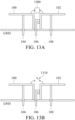
- Fig. 13A is a schematic diagram of an antenna device in accordance with some embodiments of the present invention.
- the difference between the antenna device in Fig. 13A and the antenna device in Fig. 1A is that a tuning circuit 1300 is electrically connected between the radiator 100 and the radiator 102.
- Fig. 13B is a schematic diagram of the antenna device in Fig. 13A in accordance with some embodiments of the present invention.
- the tuning circuit 1300 can be a switch 1310, but the present invention is not limited thereto.
- the switch 1310 is off to disconnect the connection between the radiator 100 and the radiator 102.
- the dipole antenna is not under work, but one of the PIFA antenna is under work, the 1310 is on to connect the radiator 100 and the radiator 102.
- Fig. 14A is a schematic diagram of an antenna device in accordance with some embodiments of the present invention.
- the difference between the antenna device in Fig. 13A and the antenna device in Fig. 1A is that an open trace 1404 is orthogonally connected to the horizontal portions of the radiator 100, an open trace 1406 is orthogonally connected to the horizontal portions of the radiator 102, a tuning circuit 1400 is electrically connected between the open trace 1404 and the ground GND, and a tuning circuit 1402 is electrically connected between the open trace 1406 and the ground GND.
- Fig. 14B is a schematic diagram of the antenna device in Fig. 14A in accordance with some embodiments of the present invention.
- the tuning circuit 1400 can be a switch 1410.
- the tuning circuit 1402 can be a switch 1412. , but the present invention is not limited thereto.
- the switch 1410 when the dipole antenna is under work to transmit the RF signals to the Z direction, the switch 1410 is on to connect the connection between the open trace 1404 and the ground GND, and the switch 1412 is on to connect the open trance 1406 and the ground GND.
- the switch 1410 is off to disconnect the connection between the open trace 1404 and the ground GND, or the switch 1412 is off to disconnect the connection between the open trance 1406 and the ground GND.
Landscapes
- Physics & Mathematics (AREA)
- Electromagnetism (AREA)
- Variable-Direction Aerials And Aerial Arrays (AREA)
- Aerials With Secondary Devices (AREA)
Abstract
Description
- This application claims the benefit of
United States Provisional Application No.63/299,449, filed on January 14, 2022 - The present invention relates to an antenna device, and, in particular, to a wide coverage shared aperture antenna.
- In current smartphone designs, different antennas are used to get coverage in another radiation direction. Therefore, these antennas may be double the necessary size. The BOM cost-including the cost of the antenna substrate and the flexible printed circuit (FPC)-may likewise be nearly double. Furthermore, the coverage of antennas using the current design may cover two sides, and these antennas can only be disposed on the edges of the phone. How to use the same antenna to get another radiation direction while reducing the antenna's size and the BOM cost has become an important topic.
- An antenna device according to the invention is defined by the independent claim. An embodiment of the present invention provides an antenna device. The antenna device includes a first antenna and a second antenna. The first antenna receives or transmits first radio frequency signals to a first direction. The second antenna receives or transmits second radio frequency signals to a second direction. The first direction is different from the second direction. Radiators of the first antenna and the second antenna are shared.
- According to the antenna device described above, the direction-angle difference between the first direction and the second direction is larger than 30 degrees.
- According to the antenna device described above, the frequency of the first radio frequency signals is the same as that of the second radio frequency signals; or the frequency of the first radio frequency signals is different from that of the second radio frequency signals.
- According to the antenna device described above, the first antenna is a dipole antenna, and the second antenna is a planar inverted-F (PIFA) liked antenna.
- According to the antenna device described above, the first antenna includes a first feed line. The second antenna includes a second feed line. The first feed line electrically couples the first radio frequency signals to the radiators of the first antenna. The second feed line electrically connects or couples the second radio frequency signals to the radiators of the second antenna.
- According to the antenna device described above, the second antenna includes a tuning circuit. The tuning circuit is electrically connected to the second feed line or to the radiators of the second antenna.
- According to the antenna device described above, the first antenna includes a tuning circuit. The tuning circuit is electrically connected to the first feed line or to the radiators of the first antenna.
- According to the antenna device described above, the tuning circuit includes a phase shifter and a switch. The phase shifter delays the phase of the second radio frequency signals. The switch shorts the second feed line to a ground, or opens the second feed line.
- According to the antenna device described above, the phase shifter includes a variable capacitor and a transmission line. The variable capacitor is electrically connected in parallel between the second feed line and the ground, and it changes the impedance of the second feed line. The transmission line is electrically connected to the second feed line in series, and it delays the phase of the second radio frequency signals.
- According to the antenna device described above, the radiators of the first antenna include a first portion and a second portion. The first feed line is disposed between the first portion and the second portion. The first portion and the second portion form the shape of a pair of gull wings.
- According to the antenna device described above, the radiators of the second antenna include the first portion of the radiators of the first antenna, the second feed line, and a ground.
- According to the antenna device described above, when the first antenna receives or transmits the first radio frequency signals to the first direction, the switch opens the second feed line. When the second antenna receives or transmits the second radio frequency signals to the second direction, the switch shorts the second feed line to the ground.
- According to the antenna device described above, the antenna device further includes a third antenna. The third antenna receives or transmits third radio frequency signals to a third direction. The third direction and the second direction are in opposite directions. The radiators of the first antenna and the third antenna are shared.
- According to the antenna device described above, the third antenna includes a third feed line. The third feed line is electrically connects or couples the third radio frequency signals to the radiators of the third antenna.
- According to the antenna device described above, the third antenna is a planar inverted-F (PIFA) antenna.
- According to the antenna device described above, the polarization direction of the first radio frequency signals is the same as the second direction or the opposite direction of the second direction. The polarization direction of the second frequency signals is the same as the first direction or the opposite direction of the first direction.
- According to the antenna device described above, the antenna device further includes a fourth antenna. The fourth antenna receives or transmits fourth radio frequency signals to the first direction. The polarization direction of the fourth radio frequency signals is a fourth direction. The fourth direction is orthogonal to the second direction.
- According to the antenna device described above, the fourth antenna includes a fourth feed line. The fourth feed line is electrically couples the fourth radio frequency signals to the radiators of the fourth antenna.
- According to the antenna device described above, the fourth antenna is a dipole antenna.
- According to the antenna device described above, the radiators of the fourth antenna include a third portion and a fourth portion. The fourth feed line is disposed between the third portion and the fourth portion. The third portion and the fourth portion form the shape of a pair of gull wings.
- The disclosure can be more fully understood by reading the subsequent detailed description with references made to the accompanying figures. It should be understood that the figures are not drawn to scale in accordance with standard practice in the industry. In fact, it is allowed to arbitrarily enlarge or reduce the size of components for clear illustration. This means that many special details, relationships and methods are disclosed to provide a complete understanding of the disclosure.
-
Fig. 1A is a schematic diagram of an antenna device in accordance with some embodiments of the present invention. -
Fig. 1B is a schematic diagram of an antenna device in accordance with some embodiments of the present invention. -
Fig. 1C is a schematic diagram of an antenna device in accordance with some embodiments of the present invention. -
Fig. 2A is a stereogram of an antenna device in accordance with some embodiments of the present invention. -
Fig. 2B is a block diagram of the antenna device inFig. 2A in accordance with some embodiments of the present invention. -
Fig. 3A is a schematic diagram of an antenna device in accordance with some embodiments of the present invention. -
Fig. 3B is a schematic diagram of a tuning circuit inFig. 3A in accordance with some embodiments of the present invention. -
Fig. 3C is a detail schematic diagram of a tuning circuit inFig. 3A in accordance with some embodiments of the present invention. -
Fig. 4A is a schematic diagram of an antenna device in accordance with some embodiments of the present invention. -
Fig. 4B is a block diagram of the antenna device inFig. 4A in accordance with some embodiments of the present invention. -
Fig. 5A is a schematic diagram of an antenna device in accordance with some embodiments of the present invention. -
Fig. 5B is a block diagram of the antenna device inFig. 5A in accordance with some embodiments of the present invention. -
Fig. 6A is a schematic diagram of an antenna device in accordance with some embodiments of the present invention. -
Fig. 6B is a schematic diagram of an antenna array including the antenna device inFig. 6A in accordance with some embodiments of the present invention. -
Fig. 6C is a block diagram of the antenna device inFig. 6A in accordance with some embodiments of the present invention. -
Fig. 7 is a schematic diagram of an antenna control system including the antenna device inFig. 2B in accordance with some embodiments of the present invention. -
Fig. 8 is a schematic diagram of an antenna control system in accordance with some embodiments of the present invention. -
Fig. 9 is a schematic diagram of an antenna control system in accordance with some embodiments of the present invention. -
Fig. 10 is a schematic diagram of an antenna control system in accordance with some embodiments of the present invention. -
Fig. 11 is a schematic diagram of an antenna control system in accordance with some embodiments of the present invention. -
Fig. 12 is a schematic diagram of an antenna control system in accordance with some embodiments of the present invention. -
Fig. 13A is a schematic diagram of an antenna device in accordance with some embodiments of the present invention. -
Fig. 13B is a schematic diagram of the antenna device inFig. 13A in accordance with some embodiments of the present invention. -
Fig. 14A is a schematic diagram of an antenna device in accordance with some embodiments of the present invention. -
Fig. 14B is a schematic diagram of the antenna device inFig. 14A in accordance with some embodiments of the present invention. - In order to make the above purposes, features, and advantages of some embodiments of the present invention more comprehensible, the following is a detailed description in conjunction with the accompanying drawing.
- Certain terms are used throughout the description and following claims to refer to particular components. As one skilled in the art will understand, electronic equipment manufacturers may refer to a component by different names. This document does not intend to distinguish between components that differ in name but not function. It is understood that the words "comprise", "have" and "include" are used in an open-ended fashion, and thus should be interpreted to mean "include, but not limited to...". Thus, when the terms "comprise" , "have" and/or "include" used in the present invention are used to indicate the existence of specific technical features, values, method steps, operations, units and/or components. However, it does not exclude the possibility that more technical features, numerical values, method steps, work processes, units, components, or any combination of the above can be added.
- The directional terms used throughout the description and following claims, such as: "on", "up", "above", "down", "below", "front", "rear", "back", "left", "right", etc., are only directions referring to the drawings. Therefore, the directional terms are used for explaining and not used for limiting the present invention. Regarding the drawings, the drawings show the general characteristics of methods, structures, and/or materials used in specific embodiments. However, the drawings should not be construed as defining or limiting the scope or properties encompassed by these embodiments. For example, for clarity, the relative size, thickness, and position of each layer, each area, and/or each structure may be reduced or enlarged.
- When the corresponding component such as layer or area is referred to as being "on another component", it may be directly on this other component, or other components may exist between them. On the other hand, when the component is referred to as being "directly on another component (or the variant thereof)", there is no component between them. Furthermore, when the corresponding component is referred to as being "on another component", the corresponding component and the other component have a disposition relationship along a top-view/vertical direction, the corresponding component may be below or above the other component, and the disposition relationship along the top-view/vertical direction is determined by the orientation of the device.
- It should be understood that when a component or layer is referred to as being "connected to" another component or layer, it can be directly connected to this other component or layer, or intervening components or layers may be present. In contrast, when a component is referred to as being "directly connected to" another component or layer, there are no intervening components or layers present.
- The electrical connection or coupling described in this disclosure may refer to direct connection or indirect connection. In the case of direct connection, the endpoints of the components on the two circuits are directly connected or connected to each other by a conductor line segment, while in the case of indirect connection, there are switches, diodes, capacitors, inductors, resistors, other suitable components, or a combination of the above components between the endpoints of the components on the two circuits, but the intermediate component is not limited thereto.
- The words "first", "second", "third", "fourth", "fifth", and "sixth" are used to describe components. They are not used to indicate the priority order of or advance relationship, but only to distinguish components with the same name.
- It should be noted that the technical features in different embodiments described in the following can be replaced, recombined, or mixed with one another to constitute another embodiment without departing from the spirit of the present invention.
-
Fig. 1A is a schematic diagram of an antenna device in accordance with some embodiments of the present invention. As shown inFig. 1A , the antenna device includes a first antenna, a second antenna, and a third antenna. The first antenna includes aradiator 100, aradiator 102, and afeed line 106. The first antenna receives or transmits first radio frequency signals to a first direction (e.g., the Z direction). Thefeed line 106 electrically couples the first radio frequency signals to theradiators feed line 106 passes through a ground GND along the Z direction and is disposed between theradiators radiators - The second antenna includes the
radiator 100, the ground GND, and afeed line 104. Theradiator 100 is shared by the first antenna and the second antenna. The second antenna receives or transmits second radio frequency signals to a second direction (e.g., the -X direction). Thefeed line 104 electrically couples the second radio frequency signals to theradiator 100 of the second antenna. Thefeed line 104 passes through the ground GND along the Z direction and is covered by theradiator 100 in view of the -Z direction. Thefeed line 104 and theradiator 100 form the shape of an inverted F, but the present invention is not limited thereto. The polarization direction of the second radio frequency signals transmitted from the second antenna is the same as the Z direction or the -Z direction. Preferably, the second antenna is a planar inverted-F (PIFA) liked antenna, but the present invention is not limited thereto. - The third antenna includes the
radiator 102, the ground GND, and afeed line 108. Theradiator 102 is shared by the first antenna and the third antenna. The third antenna receives or transmits third radio frequency signals to a third direction (e.g., the X direction). Thefeed line 108 electrically couples the third radio frequency signals to theradiator 102 of the third antenna. Thefeed line 108 passes through the ground GND along the Z direction and is covered by theradiator 102 in view of the -Z direction. Thefeed line 108 and theradiator 102 form the shape of an inverted F, but the present invention is not limited thereto. The polarization direction of the third radio frequency signals transmitted from the third antenna is the same as the Z direction or the -Z direction. Preferably, the third antenna is a PIFA antenna, but the present invention is not limited thereto. Preferably, the frequency of the first radio frequency signals is the same or different from that of the second radio frequency signals. The frequency of the second radio frequency signals is the same or different from that of the third radio frequency signals. The frequency of the third radio frequency signals is the same or different from that of the first radio frequency signals. -
Fig. 1B is a schematic diagram of an antenna device in accordance with some embodiments of the present invention. The difference between the antenna device inFig. 1B and the antenna deviceFig. 1A is that thefeed line 104 of the second antenna inFig. 1B electrically connects the second radio frequency signals to theradiator 100 of the second antenna, and thefeed line 108 of the third antenna inFig. 1B electrically connects the third radio frequency signals to theradiator 102 of the third antenna. Preferably, thefeed line 104 of the second antenna electrically connects to the horizontal (e.g., the X direction) portion of theradiator 100. Thefeed line 108 of the third antenna electrically connects to the vertical (e.g. the Z direction) portion of theradiator 102. -
Fig. 1C is a schematic diagram of an antenna device in accordance with some embodiments of the present invention. The difference between the antenna device inFig. 1C and the antenna deviceFig. 1A is that thefeed line 104 of the second antenna inFig. 1C electrically connects the second radio frequency signals to theradiator 100 of the second antenna, and thefeed line 108 of the third antenna inFig. 1C electrically connects the third radio frequency signals to theradiator 102 of the third antenna. Preferably, thefeed line 104 of the second antenna electrically connects to the vertical (e.g., the Z direction) portion of theradiator 100. Thefeed line 108 of the third antenna electrically connects to the horizontal (e.g. the X direction) portion of theradiator 102. -
Fig. 2A is a stereogram of an antenna device in accordance with some embodiments of the present invention. As shown inFig. 2A , the antenna device includes a the first antenna inFig. 1B , the second antenna inFig. 1B , the third antenna inFig. 1B , and a fourth antenna. The fourth antenna receives or transmits fourth radio frequency signals to the first direction (e.g., the Z direction). The fourth antenna includes aradiator 200, aradiator 202, and afeed line 206. Thefeed line 206 electrically couples the fourth radio frequency signals to theradiators feed line 206 passes through the ground GND along the Z direction and is disposed between theradiators radiators feed lines radiators Fig. 2A . However, the polarization direction of the first radio frequency signals transmitted from the first antenna is the same as the X direction or the -X direction inFig. 2A . In other words, the polarization direction of the fourth radio frequency signals is orthogonal to that of the first radio frequency signals. Preferably, the fourth antenna is a dipole antenna, but the present invention is not limited thereto. Preferably, the angle difference between the first direction (e.g., the Z direction inFig. 2A ) and the second direction (e.g., the X direction inFig. 2A ) is larger than 30 degrees. For example, the angle difference between the Z direction inFig. 2A and the X direction inFig. 2A is 90 degrees, but the present invention is not limited thereto. -
Fig. 2B is a block diagram of the antenna device inFig. 2A in accordance with some embodiments of the present invention. As shown inFig. 2B , theantenna device 210 includes the first antenna, the second antenna, the third antenna, and the fourth antenna inFig. 2A . In detail, the first antenna includes thefeed line 106 to receive or transmit the first radio frequency signals. The second antenna includes thefeed line 104 to receive or transmit the second radio frequency signals. The third antenna includes thefeed line 108 to receive or transmit the third radio frequency signals. The fourth antenna includes thefeed line 206 to receive or transmit the fourth radio frequency signals. The first radio frequency signals are radiated by theradiators radiator 100 and thefeed line 104 of the second antenna, and the ground GND. The third radio frequency signals are radiated by theradiator 102 and thefeed line 108 of the third antenna, and the ground GND. The fourth radio frequency signals are radiated by theradiators -
Fig. 3A is a schematic diagram of an antenna device in accordance with some embodiments of the present invention. The difference between the antenna device inFig. 3A and the antenna device inFig. 1B is that the second antenna further includes atuning circuit 300 electrically connected in series on thefeed line 104, and the third antenna further includes atuning circuit 302 electrically connected in series on thefeed line 108. Thetuning circuit 300 is the same as thetuning circuit 302.Fig. 3B is a schematic diagram of thetuning circuit 300 inFig. 3A in accordance with some embodiments of the present invention. Thetuning circuit 300 includes aphase shifter 310 and aswitch 312. Thetuning circuit 302 includes aphase shifter 320 and aswitch 322. Thephase shifter 310 delays the phase of the second radio frequency signals. Theswitch 312 shorts thefeed line 104 to the ground GND or opens thesecond feed line 104 according which antenna is currently under work. Thephase shifter 320 delays the phase of the third radio frequency signals. Theswitch 322 shorts thefeed line 108 to the ground GND or opens thesecond feed line 108 according which antenna is currently under work. For example, when the first antenna including theradiators feed line 106 is under work, the first antenna receives or transmits the first radio frequency signals to the first direction (e.g., the Z direction), theswitch 312 shorts thefeed line 104 to the ground GND and theswitch 322 shorts thefeed line 108 to the ground GND. - Preferably, when the second antenna including the
radiator 100, thefeed line 104, and the ground GND is currently under work, the second antenna receives or transmits the second radio frequency signals to the second direction (e.g., the -X direction), theswitch 312 opens thefeed line 104 and theswitch 322 shorts thefeed line 108 to the ground GND. Preferably, when the third antenna including theradiator 102, thefeed line 108, and the ground is currently under work, the third antenna receives or transmits the third radio frequency signals to the third direction (e.g., the X direction), theswitch 322 opens thefeed line 108 and theswitch 312 shorts thefeed line 104 to the ground GND. -
Fig. 3C is a detail schematic diagram of thetuning circuit 300 inFig. 3A in accordance with some embodiments of the present invention. As shown inFig. 3C , thephase shifter 310 inFig. 3B includes avariable capacitor 314 and adelay line 316. Thevariable capacitor 314 is electrically connected in parallel between thefeed line 104 and the ground GND, and changes the impedance of thefeed line 104. Thedelay line 316 is electrically connected to thefeed line 104 in series, and delays the phase of the second radio frequency signals. Theswitch 312 is electrically connected in parallel between thefeed line 104 and the ground GND. By tuning the capacitance of thevariable capacitor 314 and/or the length of thedelay line 316, the impedance of thefeed line 104 can be match to a predetermined value (for example, 50 ohms). Similarly, thephase shifter 320 inFig. 3B includes a variable capacitor (not shown) and a delay line (not shown). The variable capacitor in thephase shifter 320 is electrically connected in parallel between thefeed line 108 and the ground GND, and changes the impedance of thefeed line 108. The delay line in thephase shifter 320 is electrically connected to thefeed line 108 in series, and delays the phase of the third radio frequency signals. Theswitch 322 is electrically connected in parallel between thefeed line 108 and the ground GND. By tuning the capacitance of the variable capacitor in thephase shifter 320 and/or the length of the delay line in thephase shifter 320, the impedance of thefeed line 108 can be match to a predetermined value (for example, 50 ohms). -
Fig. 4A is a schematic diagram of an antenna device in accordance with some embodiments of the present invention. The difference between the antenna device inFig. 4A and the antenna device inFig. 2A is that the antenna device inFig. 4A further includes a fifth antenna including theradiator 200, afeed line 400, and the ground GND, and a sixth antenna including theradiator 202, afeed line 402, and the ground. The fifth antenna receives or transmits fifth radio frequency signals to the -Y direction. Thefeed line 400 electrically connects the fifth radio frequency signals to theradiator 200. Thefeed line 400 passes through the ground GND along the Z direction and is covered by theradiator 200 in view of the -Z direction. Theradiator 200 is shared by the fourth antenna and the fifth antenna. The polarization direction of the fifth radio frequency signals is the same as the Z direction or the -Z direction. The sixth antenna receives or transmits sixth radio frequency signals to the Y direction. Thefeed line 402 electrically connects the sixth radio frequency signals to theradiator 202. Thefeed line 402 passes through the ground GND along the Z direction and is covered by theradiator 202 in view of the -Z direction. Theradiator 202 is shared by the fourth antenna and the sixth antenna. The polarization direction of the sixth radio frequency signals is the same as the Z direction or the -Z direction. Preferably, the fifth antenna and the sixth antenna are PIFA antenna, but the present invention is not limited thereto. -
Fig. 4B is a block diagram of the antenna device inFig. 4A in accordance with some embodiments of the present invention. As shown inFig. 4B , theantenna device 410 includes the first antenna, the second antenna, the third antenna, the fourth antenna, the fifth antenna, and the sixth antenna inFig. 4A . In detail, the first antenna includes thefeed line 106 to receive or transmit the first radio frequency signals. The second antenna includes thefeed line 104 to receive or transmit the second radio frequency signals. The third antenna includes thefeed line 108 to receive or transmit the third radio frequency signals. The fourth antenna includes thefeed line 206 to receive or transmit the fourth radio frequency signals. The fifth antenna includes thefeed line 400 to receive or transmit the fifth radio frequency signals. The sixth antenna includes thefeed line 402 to receive or transmit the sixth radio frequency signals. - In some embodiments of
Fig. 4A and Fig. 4B , the first radio frequency signals are radiated by theradiators radiator 100 and thefeed line 104 of the second antenna, and the ground GND. The third radio frequency signals are radiated by theradiator 102 and thefeed line 108 of the third antenna, and the ground GND. The fourth radio frequency signals are radiated by theradiators radiator 200 and thefeed line 400 of the fifth antenna, and the ground GND. The sixth radio frequency signals are radiated by theradiator 202 and thefeed line 402 of the sixth antenna, and the ground GND. -
Fig. 5A is a schematic diagram of an antenna device in accordance with some embodiments of the present invention. The difference between the antenna device inFig. 5A and the antenna device inFig. 4A is that the antenna device inFig. 5A is obtained by clockwise rotating the antenna device inFig. 4A about 45 degrees. That is, the first antenna including theradiators feed line 106 receives or transmits the first radio frequency signals to the Z direction. However, the polarization direction of the first radio frequency signals is equal to the direction between the X direction and the -Y direction. In detail, the polarization direction of the first radio frequency signals is equal to the direction with the direction-angle difference of -45 degrees from the X direction, or the direction with the direction-angle difference of 135 degrees from the X direction. Preferably, the second antenna including theradiator 100, thefeed line 104, and the ground GND receives or transmits the second radio frequency signals to the direction between the X direction and the -Y direction. In detail, the direction between the X direction and the -Y direction may be the direction with the direction-angle difference of -45 degrees from the X direction. The polarization direction of the second radio frequency signals is equal to the Z direction or the -Z direction. - The third antenna including the
radiator 102, thefeed line 108, and the ground GND receives or transmits the third radio frequency signals to the direction between the -X direction and the Y direction. In detail, the direction between the -X direction and the Y direction may be the direction with the direction-angle difference of 135 degrees from the X direction. The polarization direction of the third radio frequency signals is equal to the Z direction or the -Z direction. The fourth antenna including theradiators feed line 206 receives or transmits the fourth radio frequency signals to the Z direction. However, the polarization direction of the fourth radio frequency signals is equal to the direction between the X direction and the Y direction. In detail, the polarization direction of the fourth radio frequency signals is equal to the direction with the direction-angle difference of 45 degrees from the X direction. - Preferably, the fifth antenna including the
radiator 200, thefeed line 400, and the ground GND receives or transmits the fifth radio frequency signals to the direction between the -X direction and the -Y direction. In detail, the direction between the -X direction and the -Y direction may be the direction with the direction-angle difference of - 135 degrees from the X direction. The polarization direction of the fifth radio frequency signals is equal to the Z direction or the -Z direction. The sixthantenna including radiator 202, thefeed line 402, and the ground GND receives or transmits the sixth radio frequency signals to the direction between the X direction and the Y direction. The direction between the X direction and the Y direction may be the direction with the direction-angle difference of 45 degrees from the X direction. The polarization direction of the sixth radio frequency signals is equal to the Z direction or the -Z direction. -
Fig. 5B is a block diagram of the antenna device inFig. 5A in accordance with some embodiments of the present invention. As shown inFig. 5B , theantenna device 510 includes the first antenna, the second antenna, the third antenna, the fourth antenna, the fifth antenna, and the sixth antenna inFig. 5A . In detail, the first antenna includes thefeed line 106 to receive or transmit the first radio frequency signals. The second antenna includes thefeed line 104 to receive or transmit the second radio frequency signals. The third antenna includes thefeed line 108 to receive or transmit the third radio frequency signals. The fourth antenna includes thefeed line 206 to receive or transmit the fourth radio frequency signals. The fifth antenna includes thefeed line 400 to receive or transmit the fifth radio frequency signals. The sixth antenna includes thefeed line 402 to receive or transmit the sixth radio frequency signals. - In some embodiments of
Fig. 5A and Fig. 5B , the first radio frequency signals are radiated by theradiators radiator 100 and thefeed line 104 of the second antenna, and the ground GND. The third radio frequency signals are radiated by theradiator 102 and thefeed line 108 of the third antenna, and the ground GND. The fourth radio frequency signals are radiated by theradiators radiator 200 and thefeed line 400 of the fifth antenna, and the ground GND. The sixth radio frequency signals are radiated by theradiator 202 and thefeed line 402 of the sixth antenna, and the ground GND. -
Fig. 6A is a schematic diagram of an antenna device in accordance with some embodiments of the present invention. The difference between theantenna device 510 inFig. 6A and the antenna device inFig. 5A is that the second radio frequency signals transmitted from the second antenna including theradiator 100, thefeed line 104, and the ground GND are combined with the sixth radio frequency signals transmitted from the sixth antenna including theradiator 202, thefeed line 402, and the ground GND. Furthermore, the fifth radio frequency signals transmitted from the fifth antenna including theradiator 200, thefeed line 400, and the ground GND are combined with the third radio frequency signals transmitted from the third antenna including theradiator 102, thefeed line 108, and the ground GND. For example, the second radio frequency signals are propagated to thedirection 610, and the sixth radio frequency signals are propagated to thedirection 620. The first subcomponents of the second radio frequency signals propagated to thedirection 612 are combined with the first subcomponents of the sixth radio frequency signals propagated to thedirection 622. Thedirection 612 is the same as thedirection 622. Preferably, thedirections direction 614 is opposite to thedirection 624, the second subcomponents of the second radio frequency signals propagated to thedirection 614 and the second subcomponents of the sixth radio frequency signals propagated to thedirection 624 are cancelled by each other. -
Fig. 6B is a schematic diagram of an antenna array including the antenna device inFig. 6A in accordance with some embodiments of the present invention. As shown inFig. 6B , the antenna array includes fourantenna devices 510 inFig. 6A , but the present invention is not limited thereto. When the second antenna and the sixth antenna in each of the antenna device are under work, the antenna array inFig. 6B may transmit the combined radio frequency signals to the X direction (e.g., thedirections 612 and 622) with higher gain and narrow beam width due to physical characteristics of the antenna array.Fig. 6C is a block diagram of the antenna device inFig. 6A in accordance with some embodiments of the present invention. As shown inFig. 6C , the antenna device further includes acombiner 600 and acombiner 602. Thecombiner 600 combines thefeed line 104 of the second antenna and thefeed line 402 of the sixth antenna to obtain a combinedfeed line 630. Thecombiner 602 combines thefeed line 108 of the third antenna and thefeed line 400 of the fifth antenna to obtain a combinedfeed line 640. Preferably, the combinedfeed line 630 controls the antenna array to receive or transmit the combined radio frequency signals to the X direction. The combinedfeed line 640 controls the antenna array to receive or transmit the combined radio frequency signals to the -X direction. The feed lines 106 and 206 controls the antenna array to receive or transmit the radio frequency signals to the Z direction with different polarization directions, respectively. -
Fig. 7 is a schematic diagram of anantenna control system 700 including theantenna device 210 inFig. 2B in accordance with some embodiments of the present invention. As shown inFig. 7 , thefeed line 104 of the second antenna in theantenna device 210 is electrically connected to anSPDT switch 702. The first output end of theSPDT switch 702 is electrically connected to an RF terminal (T/R) 720. The second output end of theSPDT switch 702 is electrically connected to aload 710. Thefeed line 106 of the first antenna in theantenna device 210 is electrically connected to anSPDT switch 704. The first output end of theSPDT switch 704 is electrically connected to aload 712. The second output end of theSPDT switch 704 is electrically connected to anRF terminal 722. Thefeed line 206 of the fourth antenna in theantenna device 210 is electrically connected to anSPDT switch 706. The first output end of theSPDT switch 706 is electrically connected to anRF terminal 724. The second output end of theSPDT switch 706 is electrically connected to aload 714. Thefeed line 108 of the third antenna in theantenna device 210 is electrically connected to anSPDT switch 708. The first output end of theSPDT switch 708 is electrically connected to aload 716. The second output end of theSPDT switch 708 is electrically connected to anRF terminal 726. Preferably, theloads RF terminals - For example, when the first antenna and the fourth antenna in the
antenna device 210 are under work, thefeed line 106 is electrically connected to theRF terminal 722 through theSPDT switch 704, and thefeed line 206 is electrically connected to theRF terminal 724 through theSPDT switch 706. At the same time, the second antenna and the third antenna in theantenna device 210 are not under work, thefeed line 104 is electrically connected to theload 710 through theSPDT switch 702, and thefeed line 108 is electrically connected to theload 716 through theSPDT switch 708. - Preferably, when the second antenna and the third antenna in the
antenna device 210 are under work, thefeed line 104 is electrically connected to theRF terminal 720 through theSPDT switch 702, and thefeed line 108 is electrically connected to theRF terminal 726 through theSPDT switch 708. At the same time, the first antenna and the fourth antenna in theantenna device 210 are not under work, thefeed line 106 is electrically connected to theload 712 through theSPDT switch 704, and thefeed line 206 is electrically connected to theload 714 through theSPDT switch 706. -
Fig. 8 is a schematic diagram of anantenna control system 800 in accordance with some embodiments of the present invention. As shown inFig. 8 , theantenna control system 800 includes anantenna device 810, a diplexer (DPX) 812, adiplexer 814, adiplexer 816, adiplexer 818, and anRFIC 802. Preferably, thediplexer 812 is used for a first PIFA antenna (PIFA1), thediplexer 814 is used for a first dipole antenna (Dipole), thediplexer 816 is used for a second dipole antenna (Dipole), and thediplexer 818 is used for a second PIFA antenna (PIFA2). Preferably, theRFIC 802 includesswitches switches block 39G RX) or transmitting (theblock 39G TX) of high band RF signals (e.g., the 39GHz RF signals) or to connect the respective diplexers to the tuning load TL. Theswitches block 28G RX) or transmitting (theblock 28G TX) of low band RF signals(e.g., the 28GHz RF signals) or to connect the respective diplexers to the tuning load TL. - Please refer to
Fig. 2A andFig. 8 at the same time. In some embodiments, theantenna device 810 includes the first PIFA antenna (the second antenna inFig. 2A ), the first dipole antenna (the first antenna inFig. 2A ), the second dipole antenna (the fourth antenna inFig. 2A ), and the second PIFA antenna (the third antenna inFig. 2A ). The feed line of the first PIFA antenna is electrically connected to thediplexer 812. The feed line of the first dipole antenna is electrically connected to thediplexer 814. The feed line of the second dipole antenna is electrically connected to thediplexer 816. The feed line of the second PIFA antenna is electrically connected to thediplexer 818. Preferably, when the first dipole antenna and the second dipole antenna are under work to transmit the high band RF signals with different polarization directions (e.g., the polarization directions H-Pol. and V-Pol.) to the Z direction, thediplexer 814 electrically connects the feed line of the first dipole antenna to theswitch 824, and theswitch 824 enables the transmitting of the high band RF signals (39G TX). Similarly, thediplexer 816 electrically connects the feed line of the second dipole antenna to theswitch 830, and theswitch 830 also enables the transmitting of the high band RF signals (39G TX). - At the same time, the first PIFA antenna and the second PIFA antenna are not under work, the
diplexer 812 electrically connects the feed line of the first PIFA antenna to theswitch 820, and theswitch 820 electrically connects the tuning load TL to thediplexer 812. Similarly, thediplexer 818 electrically connects the feed line of the second PIFA antenna to theswitch 834, and theswitch 834 electrically connects the tuning load TL to thediplexer 818. - Preferably, when the first PIFA antenna is under work to receive the low band RF signals from the X direction, the
diplexer 812 electrically connects the feed line of the first PIFA antenna to theswitch 822, and theswitch 822 enables the receiving of the low band RF signals (28G RX). At the same time, the second PIFA antenna, the first dipole antenna, and the second dipole antenna are not work, thediplexer 818 electrically connects the feed line of the second PIFA antenna to theswitch 832, and theswitch 832 electrically connects the tuning load TL to thediplexer 812. Thediplexer 814 electrically connects the feed line of the first dipole antenna to the r theswitch 826, and theswitch 824 electrically connects the tuning load TL to thediplexer 814. Similarly, thediplexer 816 electrically connects the feed line of the second dipole antenna to theswitch 828, and theswitch 828 electrically connects the tuning load TL to thediplexer 816. -
Fig. 9 is a schematic diagram of anantenna control system 900 in accordance with some embodiments of the present invention. As shown inFig. 9 , theantenna control system 900 includes anantenna device 910, anexternal IC 902 nearby theantenna device 910, diplexers (DPX) 920, 922, 924, and 926, and anRFIC 904. Please refer toFig. 2A andFig. 9 at the same time. Preferably, theantenna device 910 includes a first PIFA antenna (PIFA1), a second PIFA antenna (PIFA2), a first dipole antenna (Dipole), and a second dipole antenna (Dipole). Theexternal IC 902 includesswitches switch 912 electrically connects to the feed line of the first PIFA antenna. The first output end of theswitch 912 electrically connects to thediplexer 920. The second output end of theswitch 912 electrically connects to the tuning load TL. The input end of theswitch 914 electrically connects to the feed line of the first dipole antenna. The first output end of theswitch 914 electrically connects to the tuning load TL. The second output end of theswitch 914 electrically connects to thediplexer 922. The input end of theswitch 916 electrically connects to the feed line of the second dipole antenna. The first output end of theswitch 916 electrically connects to thediplexer 924. The second output end of theswitch 916 electrically connects to the tuning load TL. The input end of theswitch 918 electrically connects to the feed line of the second PIFA antenna. The first output end of theswitch 918 electrically connects to the tuning load TL. The second output end of theswitch 918 electrically connects to thediplexer 926. Preferably, the tuning load TL may be, for example, impedance tuners, open traces, short traces, tuning capacitors, tuning inductors, and phase shifters, but the present invention is not limited thereto. - The
RFIC 904 includesswitches switches block 39G RX) or transmitting (theblock 39G TX) of high band RF signals (e.g., the 39GHz RF signals). Theswitches block 28G RX) or transmitting (theblock 28G TX) of low band RF signals (e.g., the 28GHz RF signals). Preferably, when the first dipole antenna and the second dipole antenna are under work to transmit the high band RF signals with different polarization directions (e.g., the polarization directions H-Pol. and V-Pol.) to the Z direction, theswitch 914 electrically connects the feed line of the first dipole antenna to thediplexer 922, and thediplexer 922 electrically connects theswitch 934, so that theswitch 934 enables the transmitting of the high band RF signals (39G TX). Theswitch 916 electrically connects the feed line of the second dipole antenna to thediplexer 924, and thediplexer 924 electrically connects theswitch 940, so that theswitch 940 enables the transmitting of the high band RF signals (39G TX). At the same time, the first PIFA antenna and the second PIFA antenna are not under work, theswitch 912 electrically connects the feed line of the first PIFA antenna to the tuning load TL, and theswitch 918 electrically connects the feed line of the second PIFA antenna to the tuning load TL. - Preferably, when the first PIFA antenna is under work to receive the high band RF signals from the X direction, the
switch 912 electrically connects the feed line of the first PIFA antenna to thediplexer 920, and thediplexer 920 electrically connects theswitch 930, so that theswitch 930 enables the receiving of the high band RF signals (39G RX). At the same time, the second PIFA antenna, the first dipole antenna, and the second dipole antenna are not under work, theswitch 918 electrically connects the feed line of the second PIFA antenna to the tuning load TL, theswitch 914 electrically connects the feed line of the first dipole antenna to the tuning load TL, and theswitch 916 electrically connects the feed line of the second dipole antenna to the tuning load TL. -
Fig. 10 is a schematic diagram of anantenna control system 1000 in accordance with some embodiments of the present invention. As shown inFig. 10 , theantenna control system 1000 includes anantenna device 1010, adiplexer 1012, adiplexer 1014, and anRFIC 1002. Please refer toFig. 2A andFig. 10 at the same time. Preferably, theantenna device 1010 includes a first PIFA antenna (PIFA1), a second PIFA antenna (PIFA2), a first dipole antenna (Dipole), and a second dipole antenna (Dipole). Thediplexer 1012 is used to electrically connect the feed line of the first dipole antenna to theswitch 1024 or theswitch 1026. Thediplexer 1014 is used to electrically connect the feed line of the second dipole antenna to theswitch 1028 or theswitch 1030. Preferably, theRFIC 1002 includesswitches switches block 39G RX) or transmitting (theblock 39G TX) of high band RF signals (e.g., the 39GHz RF signals). Theswitches block 28G RX) or transmitting (theblock 28G TX) of low band RF signals (e.g., the 28GHz RF signals). - Preferably, when the first dipole antenna and the second dipole antenna are under work to transmit the high band RF signals with different polarization directions (e.g., the polarization directions H-Pol. and V-Pol.) to the Z direction, the
diplexer 1012 electrically connects theswitch 1024, and theswitch 1024 enables the transmitting of the high band RF signals (39G TX). Thediplexer 1014 electrically connects theswitch 1030, and theswitch 1030 enables the transmitting of the high band RF signals (39G TX). At the same time, the first PIFA antenna and the second PIFA antenna are not under work, theswitch 1020 electrically connects the high band feed line of the first PIFA antenna to the tuning load TL, and theswitch 1022 electrically connects the low band feed line of the first PIFA antenna to the tuning load TL. Similarly, theswitch 1032 electrically connects the low band feed line of the second PIFA antenna, and theswitch 1034 electrically connects the high band feed line of the second PIFA antenna. - Preferably, when the second PIFA antenna is under work to receive the low band RF signals from the -X direction, the
switch 1032 enables the receiving of the low band RF signals (28G RX), but theswitch 1034 electrically connects the high band feed line of the second PIFA antenna to the tuning load TL. At the same time, the first PIFA antenna, the first dipole antenna, and the second dipole antenna are not under work, theswitch 1020 electrically connects the high band feed line of the first PIFA antenna to the tuning load TL, and theswitch 1022 electrically connects the low band feed line of the first PIFA antenna to the tuning load TL. Thediplexer 1012 electrically connects theswitch 1024 or theswitch 1026 to the feed line of the first dipole antenna, and theswitch 1024 or theswitch 1026 electrically connects the feed line of the first dipole antenna to the tuning load TL. Similarly, thediplexer 1014 electrically connects theswitch 1028 or theswitch 1030 to the feed line of the second dipole antenna, and theswitch 1028 or theswitch 1030 electrically connects the feed line of the second dipole antenna to the tuning load TL. -
Fig. 11 is a schematic diagram of anantenna control system 1100 in accordance with some embodiments of the present invention. As shown inFig. 11 , theantenna control system 1100 includes anantenna device 1101, anexternal IC 1102 nearby theantenna device 1101, adiplexer 1120, adiplexer 1122, and anRFIC 1104. Please refer toFig. 2A andFig. 11 at the same time. Preferably, theantenna device 1101 includes a first PIFA antenna (PIFA1), a second PIFA antenna (PIFA2), a first dipole antenna (Dipole), and a second dipole antenna (Dipole). Theexternal IC 1102 includesswitches switch 1112 electrically connects the high band feed line of the first PIFA antenna. The second input end of theswitch 1112 electrically connects the low band feed line of the first PIFA antenna. The first output end of theswitch 1112 electrically connects theswitch 1130. The second output end of theswitch 1112 electrically connects theswitch 1132. The third output end of theswitch 1112 electrically connects the tuning load TL. Preferably, the input end of theswitch 1114 electrically connects the feed line of the first dipole antenna. The first output end of theswitch 1114 electrically connects the tuning load TL. The second output end of theswitch 1114 electrically connects thediplexer 1120. The input end of theswitch 1116 electrically connects the feed line of the second dipole antenna. The first output end of theswitch 1116 electrically connects thediplexer 1122. The second output end of theswitch 1116 electrically connects the tuning load TL. The first input end of theswitch 1118 electrically connects the low band feed line of the second PIFA antenna. The second input end of theswitch 1118 electrically connects the high band feed line of the second PIFA antenna. The first output end of theswitch 1118 electrically connects the tuning load TL. The second output end of theswitch 1118 electrically connects theswitch 1142. The third output end of theswitch 1118 electrically connects theswitch 1144. - The
diplexer 1120 is used to electrically connect the feed line of the first dipole antenna to theswitch 1134 or theswitch 1136. Thediplexer 1122 is used to electrically connect the feed line of the second dipole antenna to theswitch 1138 or theswitch 1140. TheRFIC 1104 includesswitches switches block 39G RX) or transmitting (theblock 39G TX) of high band RF signals (e.g., the 39GHz RF signals). Theswitches block 28G RX) or transmitting (theblock 28G TX) of low band RF signals (e.g., the 28GHz RF signals). Preferably, when the first dipole antenna and the second dipole antenna are under work to transmit the low band RF signals with different polarization directions (e.g., the polarization directions H-Pol. and V-Pol.) to the Z direction, theswitch 1114 electrically connects the feed line of the first dipole antenna to thediplexer 1120, and thediplexer 1120 electrically connects the feed line of the first dipole antenna to theswitch 1136, so that theswitch 1136 enables the transmitting of the low band RF signals (28G TX). Theswitch 1116 electrically connects the feed line of the second dipole antenna to thediplexer 1122, and thediplexer 1122 electrically connects the feed line of the second dipole antenna to theswitch 1138, so that theswitch 1138 enables the transmitting of the low band RF signals (28G TX). At the same time, the first PIFA antenna and the second PIFA antenna are not under work, theswitch 1112 electrically connects the high band feed line and/or the low band feed line of the first PIFA antenna to the tuning load TL, and theswitch 1118 electrically connects the high band feed line and/or the low band feed line of the second PIFA antenna to the tuning load TL. Preferably, the tuning load TL may be, for example, impedance tuners, open traces, short traces, tuning capacitors, tuning inductors, and phase shifters, but the present invention is not limited thereto. -
Fig. 12 is a schematic diagram of anantenna control system 1200 in accordance with some embodiments of the present invention. As shown inFig. 12 , thecontrol system 1200 includes anantenna device 1201, an RFIC 1202, a diplexer (DPX) 1210, and adiplexer 1212. Please refer toFig. 2A andFig. 11 at the same time. Preferably, theantenna device 1201 includes a first PIFA antenna (PIFA1), a second PIFA antenna (PIFA2), a first dipole antenna (Dipole), and a second dipole antenna (Dipole). Thediplexer 1210 is used to electrically connect the feed line of the first dipole antenna to theswitch 1224 or theswitch 1226. Thediplexer 1212 is used to electrically connect the feed line of the second dipole antenna to theswitch 1228 or theswitch 1230. The RFIC 1202 includesswitches switches block 39G RX) or transmitting (theblock 39G TX) of high band RF signals (e.g., the 39GHz RF signals), or to electrically connect the feed line of theantenna device 1201 to the tuning loads TL. Theswitches block 28G RX) or transmitting (theblock 28G TX) of low band RF signals (e.g., the 28GHz RF signals), or to electrically connect the feed line of theantenna device 1201 to the tuning loads TL. Theswitches antenna device 1201. Theswitch 1222 electrically connects the feed line of the first PIFA antenna. Theswitch 1234 electrically connects the feed line of the second PIFA antenna. - Preferably, when the first dipole antenna and the second dipole antenna are under work to transmit the high band RF signals with different polarization directions (e.g., the polarization directions H-Pol. and V-Pol.) to the Z direction, the
diplexer 1210 electrically connects the feed line of the first dipole antenna to theswitch 1224, and theswitch 1224 enables the transmitting of the high band RF signals (39G TX). Thediplexer 1212 electrically connects the feed line of the second dipole antenna to theswitch 1230, and theswitch 1230 enables the transmitting of the high band RF signals (39G TX). At the same time, theswitch 1222 electrically connects the feed line of the first PIFA antenna to the tuning load TL, and theswitch 1234 electrically connects the feed line of the first PIFA antenna to the tuning load TL. - Preferably, when the first PIFA antenna is under work to receive the low band RF signals from the X direction, the
switch 1222 enables the receiving of the low band RF signals (28G RX). At the same time, thediplexer 1210 electrically connects theswitch 1224 or theswitch 1226 to the feed line of the first dipole antenna, and theswitch 1224 or theswitch 1226 electrically connects the feed line of the first dipole antenna to the tuning load TL. Thediplexer 1212 electrically connects theswitch 1228 or theswitch 1230 to the feed line of the second dipole antenna, and theswitch 1228 or theswitch 1230 electrically connects the feed line of the second dipole antenna to the tuning load TL. Theswitch 1234 electrically connects the feed line of the second PIFA antenna to the tuning load TL. -
Fig. 13A is a schematic diagram of an antenna device in accordance with some embodiments of the present invention. The difference between the antenna device inFig. 13A and the antenna device inFig. 1A is that atuning circuit 1300 is electrically connected between theradiator 100 and theradiator 102.Fig. 13B is a schematic diagram of the antenna device inFig. 13A in accordance with some embodiments of the present invention. As shown inFig. 13B , thetuning circuit 1300 can be aswitch 1310, but the present invention is not limited thereto. Preferably, when the dipole antenna is under work to transmit the RF signals to the Z direction, theswitch 1310 is off to disconnect the connection between theradiator 100 and theradiator 102. Preferably, when the dipole antenna is not under work, but one of the PIFA antenna is under work, the 1310 is on to connect theradiator 100 and theradiator 102. -
Fig. 14A is a schematic diagram of an antenna device in accordance with some embodiments of the present invention. The difference between the antenna device inFig. 13A and the antenna device inFig. 1A is that anopen trace 1404 is orthogonally connected to the horizontal portions of theradiator 100, anopen trace 1406 is orthogonally connected to the horizontal portions of theradiator 102, atuning circuit 1400 is electrically connected between theopen trace 1404 and the ground GND, and atuning circuit 1402 is electrically connected between theopen trace 1406 and the ground GND. -
Fig. 14B is a schematic diagram of the antenna device inFig. 14A in accordance with some embodiments of the present invention. As shown inFig. 14B , thetuning circuit 1400 can be aswitch 1410. Thetuning circuit 1402 can be aswitch 1412. , but the present invention is not limited thereto. Preferably, when the dipole antenna is under work to transmit the RF signals to the Z direction, theswitch 1410 is on to connect the connection between theopen trace 1404 and the ground GND, and theswitch 1412 is on to connect theopen trance 1406 and the ground GND. Preferably, when the dipole antenna is not under work, theswitch 1410 is off to disconnect the connection between theopen trace 1404 and the ground GND, or theswitch 1412 is off to disconnect the connection between theopen trance 1406 and the ground GND. - While the invention has been described by way of example and in terms of the preferred embodiments, it should be understood that the invention is not limited to the disclosed embodiments. On the contrary, it is intended to cover various modifications and similar arrangements (as would be apparent to those skilled in the art). Therefore, the scope of the appended claims should be accorded the broadest interpretation so as to encompass all such modifications and similar arrangements.
Claims (15)
- An antenna device, comprising:a first antenna (100, 102, 106), configured to receive or transmit first radio frequency signals to a first direction; anda second antenna (100, 104, GND), configured to receive or transmit second radio frequency signals to a second direction;wherein the first direction is different from the second direction;wherein radiators (100) of the first antenna (100, 102, 106) and the second antenna (100, 104, GND) are shared.
- The antenna device as claimed in claim 1, wherein the direction-angle difference between the first direction and the second direction is larger than 30 degrees.
- The antenna device as claimed in claim 1,wherein the frequency of the first radio frequency signals is the same as that of the second radio frequency signals; or the frequency of the first radio frequency signals is different from that of the second radio frequency signals, and/orwherein the first antenna (100, 102, 106) is a dipole antenna, and the second antenna (100, 104, GND) is a planar inverted-F (PIFA) liked antenna.
- The antenna device as claimed in any one of claims 1 to 3, wherein the first antenna (100, 102, 106) comprises a first feed line (106), and the second antenna (100, 104, GND) comprises a second feed line (104); wherein the first feed line (106) electrically couples the first radio frequency signals to the radiators of the first antenna (100, 102, 106); wherein the second feed line (104) electrically connects or couples the second radio frequency signals to the radiators of the second antenna (100, 104, GND).
- The antenna device as claimed in claim 4,wherein the second antenna (100, 104, GND) comprises a tuning circuit (300); wherein the tuning circuit (300) is electrically connected to the second feed line (104) or is electrically connected to the radiators of the second antenna (100, 104, GND), orwherein the first antenna (100, 102, 106) comprises a tuning circuit (300); wherein the tuning circuit (300) is electrically connected to the first feed line (106) or is electrically connected to the radiators of the first antenna.
- The antenna device as claimed in claim 5, wherein the tuning circuit (300) comprises:a phase shifter (310), configured to delay the phase of the second radio frequency signals; anda switch (322), configured to short the second feed line (104) to a ground, or to open the second feed line (104).
- The antenna device as claimed in claim 6, wherein the phase shifter (310) comprises:a variable capacitor (314), electrically connected in parallel between the second feed line (104) and the ground, wherein the variable capacitor (315) is configured to change the impedance of the second feed line (104); anda transmission line (316), electrically connected to the second feed line (104) in series, wherein the variable capacitor (314) is configured to delay the phase of the second radio frequency signals.
- The antenna device as claimed in any one of claims 4 to 7, wherein the radiators of the first antenna (100, 102, 106) comprise a first portion and a second portion; the first feed line (106) is disposed between the first portion and the second portion, and the first portion and the second portion form the shape of a pair of gull wings, wherein the radiators of the second antenna (100, 104, GND) preferably comprise the first portion of the radiators of the first antenna (100, 102, 106), the second feed line (104), and a ground.
- The antenna device as claimed in any one of claims 6 to 8, wherein when the first antenna (100, 102, 106) receives or transmits the first radio frequency signals to the first direction, the switch shorts the second feed line (104) to the ground; when the second antenna (100, 104, GND) receives or transmits the second radio frequency signals to the second direction, the switch opens the second feed line (104).
- The antenna device as claimed in any one of claims 1 to 9, further comprising:a third antenna, configured to receive or transmit third radio frequency signals to a third direction;wherein the third direction is opposite to the second direction;wherein the radiators of the first antenna (100, 102, 106) and the third antenna are shared.
- The antenna device as claimed in claim 10,wherein the third antenna comprises a third feed line (108); wherein the third feed line electrically connects or couples the third radio frequency signals to the radiators of the third antenna; wherein the frequency of the third radio frequency signals is the same as that of the second radio frequency signals; or the frequency of the third radio frequency signals is different from that of the second radio frequency signals, and/orwherein the third antenna is a planar inverted-F, PIFA, liked antenna.
- The antenna device as claimed in any one of claims 1 to 11, wherein the polarization direction of the first radio frequency signals is the same as the second direction or the opposite direction of the second direction; wherein the polarization direction of the second frequency signals is the same as the first direction or the opposite direction of the first direction.
- The antenna device as claimed in any one of claims 1 to 12, further comprising:a fourth antenna, configured to receive or transmit fourth radio frequency signals to the first direction;wherein the polarization direction of the fourth radio frequency signals is a fourth direction;wherein the fourth direction is orthogonal to the second direction,wherein the fourth antenna is preferably a dipole antenna.
- The antenna device as claimed in claim 13,
wherein the fourth antenna comprises a fourth feed line (206); wherein the fourth feed line (206) electrically couples the fourth radio frequency signals to the radiators of the fourth antenna; wherein the frequency of the fourth radio frequency signals is the same as that of the first radio frequency signals; or the frequency of the fourth radio frequency signals is different from that of the first radio frequency signals. - The antenna device as claimed in claim 14, wherein the radiators of the fourth antenna comprise a third portion and a fourth portion; the fourth feed line is disposed between the third portion and the fourth portion, and the third portion and the fourth portion form the shape of a pair of gull wings.
Applications Claiming Priority (2)
| Application Number | Priority Date | Filing Date | Title |
|---|---|---|---|
| US202263299449P | 2022-01-14 | 2022-01-14 | |
| US18/146,570 US20230231307A1 (en) | 2022-01-14 | 2022-12-27 | Antenna |
Publications (1)
| Publication Number | Publication Date |
|---|---|
| EP4213303A1 true EP4213303A1 (en) | 2023-07-19 |
Family
ID=84923180
Family Applications (1)
| Application Number | Title | Priority Date | Filing Date |
|---|---|---|---|
| EP23151139.5A Pending EP4213303A1 (en) | 2022-01-14 | 2023-01-11 | Antenna |
Country Status (3)
| Country | Link |
|---|---|
| US (1) | US20230231307A1 (en) |
| EP (1) | EP4213303A1 (en) |
| TW (1) | TWI867408B (en) |
Citations (3)
| Publication number | Priority date | Publication date | Assignee | Title |
|---|---|---|---|---|
| WO2006062060A1 (en) * | 2004-12-09 | 2006-06-15 | Matsushita Electric Industrial Co., Ltd. | Radio antenna device and mobile radio device using the same |
| WO2009044540A1 (en) * | 2007-10-02 | 2009-04-09 | Panasonic Corporation | Portable wireless communication device |
| US20210313695A1 (en) * | 2020-01-10 | 2021-10-07 | Shenzhen Sunway Communication Co., Ltd. | 5g mmw dual-polarized antenna module and handheld device |
Family Cites Families (7)
| Publication number | Priority date | Publication date | Assignee | Title |
|---|---|---|---|---|
| EP1756914A4 (en) * | 2004-04-12 | 2008-04-02 | Airgain Inc | Switched multi-beam antenna |
| US7868818B2 (en) * | 2006-12-21 | 2011-01-11 | Bae Systems, Plc | Multi-element antenna |
| US8570233B2 (en) * | 2010-09-29 | 2013-10-29 | Laird Technologies, Inc. | Antenna assemblies |
| EP3683891B1 (en) * | 2017-10-19 | 2024-04-10 | Sony Group Corporation | Antenna device |
| TWI671951B (en) * | 2018-03-09 | 2019-09-11 | 啟碁科技股份有限公司 | Smart antenna device |
| US11387557B2 (en) * | 2019-07-10 | 2022-07-12 | Mediatek Inc. | Antenna for multi-broadband and multi-polarization communication |
| CN112751168B (en) * | 2019-10-31 | 2022-11-08 | Oppo广东移动通信有限公司 | Antenna modules and electronic equipment |
-
2022
- 2022-12-27 US US18/146,570 patent/US20230231307A1/en active Pending
-
2023
- 2023-01-11 EP EP23151139.5A patent/EP4213303A1/en active Pending
- 2023-01-13 TW TW112101506A patent/TWI867408B/en active
Patent Citations (3)
| Publication number | Priority date | Publication date | Assignee | Title |
|---|---|---|---|---|
| WO2006062060A1 (en) * | 2004-12-09 | 2006-06-15 | Matsushita Electric Industrial Co., Ltd. | Radio antenna device and mobile radio device using the same |
| WO2009044540A1 (en) * | 2007-10-02 | 2009-04-09 | Panasonic Corporation | Portable wireless communication device |
| US20210313695A1 (en) * | 2020-01-10 | 2021-10-07 | Shenzhen Sunway Communication Co., Ltd. | 5g mmw dual-polarized antenna module and handheld device |
Also Published As
| Publication number | Publication date |
|---|---|
| US20230231307A1 (en) | 2023-07-20 |
| TWI867408B (en) | 2024-12-21 |
| TW202329534A (en) | 2023-07-16 |
Similar Documents
| Publication | Publication Date | Title |
|---|---|---|
| US11024955B2 (en) | Antenna module and communication apparatus | |
| US11936096B2 (en) | Wiring substrate, antenna module, and communication device | |
| US7289064B2 (en) | Compact multi-band, multi-port antenna | |
| US20190123441A1 (en) | Multi-antenna module and mobile terminal | |
| US11710903B2 (en) | Antenna-like matching component | |
| WO2018230475A1 (en) | Antenna module and communication device | |
| US12126070B2 (en) | Antenna module and communication device equipped with the same | |
| US10535926B2 (en) | Antenna and antenna module comprising the same | |
| EP3678260A1 (en) | Multiple-input multiple-output antenna device for terminal and method for realizing transmission of antenna signal | |
| US12095163B2 (en) | Antenna module and communication device equipped with the same | |
| WO2011078029A1 (en) | Array antenna device with shortest wiring distance to antenna element | |
| CN112313831B (en) | Three distributors | |
| US12068526B2 (en) | Antenna device | |
| US20230231307A1 (en) | Antenna | |
| US20240313423A1 (en) | Antenna module and communication apparatus equipped with the same | |
| US20240178578A1 (en) | Antenna device | |
| US11095320B2 (en) | Communication system and communication method | |
| CN116454603A (en) | Antenna device | |
| CN118715722A (en) | Electronic equipment and communication systems | |
| US20170229780A1 (en) | Planar printed antenna and system | |
| EP4723375A1 (en) | Electronic telecommunication device hosting antennae | |
| EP4258474A1 (en) | Edge enabled void constructions | |
| US20250023243A1 (en) | Antenna module | |
| CN109742523B (en) | Antenna device | |
| KR20010004076A (en) | Amnidirectional antenna |
Legal Events
| Date | Code | Title | Description |
|---|---|---|---|
| PUAI | Public reference made under article 153(3) epc to a published international application that has entered the european phase |
Free format text: ORIGINAL CODE: 0009012 |
|
| STAA | Information on the status of an ep patent application or granted ep patent |
Free format text: STATUS: THE APPLICATION HAS BEEN PUBLISHED |
|
| AK | Designated contracting states |
Kind code of ref document: A1 Designated state(s): AL AT BE BG CH CY CZ DE DK EE ES FI FR GB GR HR HU IE IS IT LI LT LU LV MC ME MK MT NL NO PL PT RO RS SE SI SK SM TR |
|
| STAA | Information on the status of an ep patent application or granted ep patent |
Free format text: STATUS: REQUEST FOR EXAMINATION WAS MADE |
|
| 17P | Request for examination filed |
Effective date: 20240117 |
|
| RBV | Designated contracting states (corrected) |
Designated state(s): AL AT BE BG CH CY CZ DE DK EE ES FI FR GB GR HR HU IE IS IT LI LT LU LV MC ME MK MT NL NO PL PT RO RS SE SI SK SM TR |