EP4213289A1 - Suppression of safety gases - Google Patents
Suppression of safety gases Download PDFInfo
- Publication number
- EP4213289A1 EP4213289A1 EP23152078.4A EP23152078A EP4213289A1 EP 4213289 A1 EP4213289 A1 EP 4213289A1 EP 23152078 A EP23152078 A EP 23152078A EP 4213289 A1 EP4213289 A1 EP 4213289A1
- Authority
- EP
- European Patent Office
- Prior art keywords
- venting
- area
- battery
- battery cell
- safety vent
- Prior art date
- Legal status (The legal status is an assumption and is not a legal conclusion. Google has not performed a legal analysis and makes no representation as to the accuracy of the status listed.)
- Granted
Links
Images

Classifications
-
- H—ELECTRICITY
- H01—ELECTRIC ELEMENTS
- H01M—PROCESSES OR MEANS, e.g. BATTERIES, FOR THE DIRECT CONVERSION OF CHEMICAL ENERGY INTO ELECTRICAL ENERGY
- H01M50/00—Constructional details or processes of manufacture of the non-active parts of electrochemical cells other than fuel cells, e.g. hybrid cells
- H01M50/30—Arrangements for facilitating escape of gases
-
- H—ELECTRICITY
- H01—ELECTRIC ELEMENTS
- H01M—PROCESSES OR MEANS, e.g. BATTERIES, FOR THE DIRECT CONVERSION OF CHEMICAL ENERGY INTO ELECTRICAL ENERGY
- H01M50/00—Constructional details or processes of manufacture of the non-active parts of electrochemical cells other than fuel cells, e.g. hybrid cells
- H01M50/20—Mountings; Secondary casings or frames; Racks, modules or packs; Suspension devices; Shock absorbers; Transport or carrying devices; Holders
- H01M50/204—Racks, modules or packs for multiple batteries or multiple cells
-
- H—ELECTRICITY
- H01—ELECTRIC ELEMENTS
- H01M—PROCESSES OR MEANS, e.g. BATTERIES, FOR THE DIRECT CONVERSION OF CHEMICAL ENERGY INTO ELECTRICAL ENERGY
- H01M50/00—Constructional details or processes of manufacture of the non-active parts of electrochemical cells other than fuel cells, e.g. hybrid cells
- H01M50/30—Arrangements for facilitating escape of gases
- H01M50/35—Gas exhaust passages comprising elongated, tortuous or labyrinth-shaped exhaust passages
-
- H—ELECTRICITY
- H01—ELECTRIC ELEMENTS
- H01M—PROCESSES OR MEANS, e.g. BATTERIES, FOR THE DIRECT CONVERSION OF CHEMICAL ENERGY INTO ELECTRICAL ENERGY
- H01M50/00—Constructional details or processes of manufacture of the non-active parts of electrochemical cells other than fuel cells, e.g. hybrid cells
- H01M50/30—Arrangements for facilitating escape of gases
- H01M50/375—Vent means sensitive to or responsive to temperature
-
- H—ELECTRICITY
- H01—ELECTRIC ELEMENTS
- H01M—PROCESSES OR MEANS, e.g. BATTERIES, FOR THE DIRECT CONVERSION OF CHEMICAL ENERGY INTO ELECTRICAL ENERGY
- H01M50/00—Constructional details or processes of manufacture of the non-active parts of electrochemical cells other than fuel cells, e.g. hybrid cells
- H01M50/30—Arrangements for facilitating escape of gases
- H01M50/383—Flame arresting or ignition-preventing means
-
- H—ELECTRICITY
- H01—ELECTRIC ELEMENTS
- H01M—PROCESSES OR MEANS, e.g. BATTERIES, FOR THE DIRECT CONVERSION OF CHEMICAL ENERGY INTO ELECTRICAL ENERGY
- H01M2200/00—Safety devices for primary or secondary batteries
- H01M2200/20—Pressure-sensitive devices
-
- H—ELECTRICITY
- H01—ELECTRIC ELEMENTS
- H01M—PROCESSES OR MEANS, e.g. BATTERIES, FOR THE DIRECT CONVERSION OF CHEMICAL ENERGY INTO ELECTRICAL ENERGY
- H01M50/00—Constructional details or processes of manufacture of the non-active parts of electrochemical cells other than fuel cells, e.g. hybrid cells
- H01M50/20—Mountings; Secondary casings or frames; Racks, modules or packs; Suspension devices; Shock absorbers; Transport or carrying devices; Holders
- H01M50/204—Racks, modules or packs for multiple batteries or multiple cells
- H01M50/207—Racks, modules or packs for multiple batteries or multiple cells characterised by their shape
- H01M50/213—Racks, modules or packs for multiple batteries or multiple cells characterised by their shape adapted for cells having curved cross-section, e.g. round or elliptic
-
- Y—GENERAL TAGGING OF NEW TECHNOLOGICAL DEVELOPMENTS; GENERAL TAGGING OF CROSS-SECTIONAL TECHNOLOGIES SPANNING OVER SEVERAL SECTIONS OF THE IPC; TECHNICAL SUBJECTS COVERED BY FORMER USPC CROSS-REFERENCE ART COLLECTIONS [XRACs] AND DIGESTS
- Y02—TECHNOLOGIES OR APPLICATIONS FOR MITIGATION OR ADAPTATION AGAINST CLIMATE CHANGE
- Y02E—REDUCTION OF GREENHOUSE GAS [GHG] EMISSIONS, RELATED TO ENERGY GENERATION, TRANSMISSION OR DISTRIBUTION
- Y02E60/00—Enabling technologies; Technologies with a potential or indirect contribution to GHG emissions mitigation
- Y02E60/10—Energy storage using batteries
Definitions
- the invention relates to a system comprising a battery mounting area and a venting area, and a method of managing a battery energy storage system.
- the disclosure pertains to the art of lithium ion batteries, and more particularly, to a battery energy storage system.
- Existing lithium ion battery cells are equipped with a safety vent.
- the safety vent is configured to relieve the internal pressure of the battery cell by venting materials, such as gases, liquid, and solids into the air surrounding the battery cells.
- the materials that are vented are typically flammable. If these materials are ignited, the resulting fire event could heat up the neighboring battery cells causing a cascading thermal event to occur. Further, the accumulation of the exhausted materials within the area surrounding the battery cells may achieve a concentration which may create a potential risk of explosion.
- a system includes a battery mounting area, a venting area fluidly isolated from the battery mounting area, and a battery cell arranged at least partially within the battery mounting area.
- the battery cell includes at least one safety vent (e.g., one or more safety vents) that is fluidly coupled to the venting area.
- the venting area may be located directly adjacent to the battery mounting area.
- the venting area may be located remotely from the battery mounting area.
- the battery cell may comprise a battery can having a first open end, a second closed end, and a sidewall extending between the first open end and the second closed end; and a cap affixed to the battery can adjacent to the first open end.
- the at least one safety vent may be formed in the sidewall.
- the at least one safety vent may also be considered as one of the one or more safety vents.
- the at least one safety vent may be formed in the cap.
- the at least one safety vent may also be considered as one of the one or more safety vents.
- the at least one safety vent may be directly coupled to the venting area.
- the at least one safety vent may also be considered as one of the one or more safety vents.
- a portion of the battery cell including the at least one safety vent may be arranged within the venting area.
- the at least one safety vent may also be considered as one of the one or more safety vents.
- the system may comprise a conduit extending between the at least one safety vent and the venting area such that the at least one safety vent is indirectly coupled to the venting area.
- the at least one safety vent may also be considered as one of the one or more safety vents.
- the system may comprise a movement mechanism operable to move exhaust materials output from the at least one safety vent to the venting area.
- the at least one safety vent may also be considered as one of the one or more safety vents.
- the system may comprise an inerting system in fluid communication with the venting area, the inerting system including: at least one spray nozzle (e.g., one or more spray nozzles), a source of inerting agent, and a delivery piping system fluidly connecting the source of inerting agent and the at least one spray nozzle.
- the at least one spray nozzle may also be considered as one of the one or more spray nozzles.
- the system may comprise a suppression system in fluid communication with the venting area, the suppression system including at least one spray nozzle (e.g., one or more spray nozzles), a source of suppression agent, and a delivery piping system fluidly connecting the source of suppression agent and the at least one spray nozzle.
- the at least one spray nozzle may also be considered as one or another of the one or more spray nozzles.
- a method of managing a battery energy storage system includes operating a battery cell arranged within a battery mounting area and venting an exhaust material from the battery cell in response to a thermal event. Venting the exhaust material from the battery cell comprises (e.g., further comprises) venting the exhaust material to a venting area fluidly isolated from the battery mounting area.
- Venting the exhaust material to the venting area may comprise venting the exhaust material directly to the venting area.
- Venting the exhaust material to the venting area may comprise venting the exhaust material to the venting area via a conduit extending between the battery cell and the venting area.
- the method may comprise inerting the exhaust material within the venting area via an inerting system.
- the method may comprise suppressing a fire within the venting area via a suppression system.
- Venting the exhaust material to the venting area fluidly isolated from the battery mounting area may comprise drawing the exhaust material into the venting area via a movement mechanism.
- Venting of the exhaust material may occur in response to an increase in a pressure within the battery cell in response to the thermal event.
- Venting of the exhaust material may occur when the pressure within the battery cell exceeds a predetermined threshold.
- the battery 20 such as a lithium ion battery for example, is illustrated.
- the battery 20, also referred to herein as a cell or battery cell includes a battery housing or can 22.
- the battery can 22 may have a first open end 24, a second sealed end 26, and at least one sidewall 28 extending between the first end 24 and the second end 26 to define a hollow interior 30 therein.
- the battery can 22 may be formed from any suitable material, including but not limited to a metal material.
- the battery can 22 illustrated in the FIGS. is generally rectangular in shape, it should be understood that examples where the battery can 22 has another configuration, such as where the battery can 22 is cylindrical in shape for example, are also within the scope of the disclosure.
- a cap or lid 32 is connected to the first open end 24 of the battery can 22 to seal the hollow interior 30.
- the cap 32 may be a generally flat panel and has a size and shape corresponding to the size and shape of the battery can 22.
- the cap 32 may, but need not be formed from the same material as the battery can 22.
- a battery unit, illustrated schematically at 34, is arranged within the hollow interior 30 of the battery can 22.
- the battery unit 34 includes an electrode assembly having a positive electrode 36 and a negative electrode 38.
- the positive and negative electrodes 36, 38 may be sheets stacked on top of one another and separated from one another by a separator 40 to form the battery unit 34.
- the stacked positive electrode 36, separator 40, and negative electrode 38 may be wound into a coil prior to installation within the hollow interior 30 of the battery can 22.
- At least one safety vent 42 may be located at a surface of the battery can 22.
- the safety vent 42 in FIG. 1 is illustrated as being positioned near the first end 24 of the battery can 22, examples including a safety vent 42 arranged at another location of the battery can 22, such as at the sidewall 28 thereof for example, and/or examples where a safety vent 42 is formed in the cap 32 are also within the scope of the disclosure.
- the safety vent 42 is closed such that the interior 30 of the battery can 22 remains hermetically sealed.
- the safety vent 42 is automatically activated.
- Activation of the safety vent 42 may include opening the safety vent 42 to exhaust material, such as one or more of gases, liquids, and solids, from the interior 30 of the battery can 22, thereby reducing the pressure within the battery can 22.
- material such as one or more of gases, liquids, and solids.
- the BESS 50 includes a plurality of substantially identical battery cells 52, such as similar to battery cell 20, for example.
- examples where a configuration of one or more of the battery cells 52 varies relative to another of the battery cells 52 is within the scope of the disclosure.
- the BESS 50 shown in the FIGS. includes a plurality of battery cells 52, it should be understood that a BESS 50 having a single battery cell is also within the scope of the disclosure.
- the BESS includes a first space or area 54, also referred to herein as a battery mounting area, and at least a portion of one or more of the battery cells 52 is mounted within battery mounting area 54. In the illustrated, non-limiting example, a majority or substantially entirety of each of the plurality of battery cells 52 is arranged within the battery mounting area 54.
- the BESS 50 includes a second space or area 56, also referred to herein as a venting area, that is fluidly isolated from the battery mounting area 54.
- the venting area 56 may be located directly adjacent to the battery mounting area 54 as shown in the FIGS., or alternatively, may be located remotely from the battery mounting area 54.
- the battery cell 52 is positioned such that at least one safety vent(s) 58 of at least one battery cell 52 is arranged in fluid communication with the venting area 56.
- each battery cell 52 includes two safety vents 58 and both safety vents 58 of each battery cell 52 are arranged within the venting area 56.
- the exhaust materials that are released from the battery cell 52 via the safety vents 58 are released directly into the venting area 56 from the interior of the battery cell 52.
- a safety vent 58 of one or more of the battery cells 52 is indirectly fluidly coupled to the venting area 56 by a pipe or other conduit 60.
- the exhaust materials are configured to flow into the venting area 56 as a result of the pressure within the battery cell 52.
- one or more movement mechanisms 62 such as a fan for example, is configured to further facilitate the flow of the exhaust materials towards the venting area 56 are also within the scope of the disclosure.
- the movement mechanism 62 may be arranged within the vent area 56, as shown in FIG. 2 .
- the flammable and/or explosive exhaust gases and other materials are substantially isolated from the battery cells 52 of the BESS 50.
- the thermal runaway of a battery cell 52 would not have a cascading effect on the adjacent battery cells 52, and the potential occurrence of a fire event within the battery mounting area 54 is significantly reduced.
- an inerting and/or suppression system 70 is arranged in fluid communication with the venting area 56.
- the inerting or suppression system 70 includes at least one spray nozzle 72 associated with the venting area 56 and a source of a suppression agent 74a and/or a source of inerting agent 74b.
- the sources of suppression agent and inerting agent 74a, 74b are in the form of self-contained pressure vessels.
- suitable suppression agents or inerting agents include, but are not limited to water, clean agent, inert gas or other approved media.
- the source of suppression agent 74a and/or the source of inerting agent 74b is arranged in fluid communication with the nozzles 72 via a delivery path defined by a delivery piping system 76.
- inerting agent from the source thereof 74b is allowed to flow through the delivery piping system 76 to the one or more spray nozzles 72 for release directly into the venting area 56.
- the system 70 may be configured to inert the exhaust materials as they are evacuated from the BESS into the venting area 56.
- the suppression agent from the source of suppression agent 74a is allowed to flow through the delivery piping system 76 to the one or more spray nozzles 72 for release directly into the venting area 56.
- Such operation of the system 70 prevents, or at least mitigates, flames present in the venting area from spreading back into the battery cell 52 or into the BESS 50.
- a single system 70 is illustrated and described herein as being operable to perform both inerting and fire suppression, it should be understood that examples where the system 70 is configured to perform only one of inerting and fire suppression are also contemplated herein.
- a secondary system having a similar or different configuration may be arranged in fluid communication with the venting area 56 to perform the other of the inerting and fire suppression.
Landscapes
- Chemical & Material Sciences (AREA)
- Chemical Kinetics & Catalysis (AREA)
- Electrochemistry (AREA)
- General Chemical & Material Sciences (AREA)
- Battery Mounting, Suspending (AREA)
- Gas Exhaust Devices For Batteries (AREA)
Abstract
Description
- The invention relates to a system comprising a battery mounting area and a venting area, and a method of managing a battery energy storage system. The disclosure pertains to the art of lithium ion batteries, and more particularly, to a battery energy storage system.
- Existing lithium ion battery cells are equipped with a safety vent. When the battery cell undergoes a thermal event, the pressure within the battery cell can exceed a threshold value. In such instances, the safety vent is configured to relieve the internal pressure of the battery cell by venting materials, such as gases, liquid, and solids into the air surrounding the battery cells. However, the materials that are vented are typically flammable. If these materials are ignited, the resulting fire event could heat up the neighboring battery cells causing a cascading thermal event to occur. Further, the accumulation of the exhausted materials within the area surrounding the battery cells may achieve a concentration which may create a potential risk of explosion.
- According to an aspect of the invention, a system includes a battery mounting area, a venting area fluidly isolated from the battery mounting area, and a battery cell arranged at least partially within the battery mounting area. The battery cell includes at least one safety vent (e.g., one or more safety vents) that is fluidly coupled to the venting area.
- The venting area may be located directly adjacent to the battery mounting area.
- The venting area may be located remotely from the battery mounting area.
- The battery cell may comprise a battery can having a first open end, a second closed end, and a sidewall extending between the first open end and the second closed end; and a cap affixed to the battery can adjacent to the first open end.
- The at least one safety vent may be formed in the sidewall. The at least one safety vent may also be considered as one of the one or more safety vents.
- The at least one safety vent may be formed in the cap. The at least one safety vent may also be considered as one of the one or more safety vents.
- The at least one safety vent may be directly coupled to the venting area. The at least one safety vent may also be considered as one of the one or more safety vents.
- A portion of the battery cell including the at least one safety vent may be arranged within the venting area. The at least one safety vent may also be considered as one of the one or more safety vents.
- The system may comprise a conduit extending between the at least one safety vent and the venting area such that the at least one safety vent is indirectly coupled to the venting area. The at least one safety vent may also be considered as one of the one or more safety vents.
- The system may comprise a movement mechanism operable to move exhaust materials output from the at least one safety vent to the venting area. The at least one safety vent may also be considered as one of the one or more safety vents.
- The system may comprise an inerting system in fluid communication with the venting area, the inerting system including: at least one spray nozzle (e.g., one or more spray nozzles), a source of inerting agent, and a delivery piping system fluidly connecting the source of inerting agent and the at least one spray nozzle. The at least one spray nozzle may also be considered as one of the one or more spray nozzles.
- The system may comprise a suppression system in fluid communication with the venting area, the suppression system including at least one spray nozzle (e.g., one or more spray nozzles), a source of suppression agent, and a delivery piping system fluidly connecting the source of suppression agent and the at least one spray nozzle. The at least one spray nozzle may also be considered as one or another of the one or more spray nozzles.
- According to another aspect of the invention, a method of managing a battery energy storage system includes operating a battery cell arranged within a battery mounting area and venting an exhaust material from the battery cell in response to a thermal event. Venting the exhaust material from the battery cell comprises (e.g., further comprises) venting the exhaust material to a venting area fluidly isolated from the battery mounting area.
- Venting the exhaust material to the venting area may comprise venting the exhaust material directly to the venting area.
- Venting the exhaust material to the venting area may comprise venting the exhaust material to the venting area via a conduit extending between the battery cell and the venting area.
- The method may comprise inerting the exhaust material within the venting area via an inerting system.
- The method may comprise suppressing a fire within the venting area via a suppression system.
- Venting the exhaust material to the venting area fluidly isolated from the battery mounting area may comprise drawing the exhaust material into the venting area via a movement mechanism.
- Venting of the exhaust material may occur in response to an increase in a pressure within the battery cell in response to the thermal event.
- Venting of the exhaust material may occur when the pressure within the battery cell exceeds a predetermined threshold.
- Optional embodiments of the present invention will now be described by way of example only and with reference to the accompanying drawings. The following descriptions should not be considered limiting in any way. With reference to the accompanying drawings, like elements are numbered alike:
-
FIG. 1 is a schematic diagram of an exemplary battery cell; -
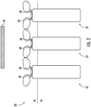
FIG. 2 is a schematic diagram of an exemplary battery energy storage system; -
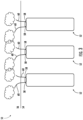
FIG. 3 is a schematic diagram of an exemplary battery energy storage system; and -
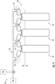
FIG. 4 is a schematic diagram of an exemplary battery energy storage system and an inerting and/or suppression system associated with the battery energy storage system. - A detailed description of one or more embodiments of the disclosed apparatus and method are presented herein by way of exemplification and not limitation with reference to the Figures.
- With reference now to
FIG. 1 , anexemplary battery 20, such as a lithium ion battery for example, is illustrated. As shown, thebattery 20, also referred to herein as a cell or battery cell, includes a battery housing or can 22. The battery can 22 may have a firstopen end 24, a second sealedend 26, and at least onesidewall 28 extending between thefirst end 24 and thesecond end 26 to define ahollow interior 30 therein. Further, the battery can 22 may be formed from any suitable material, including but not limited to a metal material. Although the battery can 22 illustrated in the FIGS. is generally rectangular in shape, it should be understood that examples where the battery can 22 has another configuration, such as where the battery can 22 is cylindrical in shape for example, are also within the scope of the disclosure. A cap orlid 32 is connected to the firstopen end 24 of the battery can 22 to seal thehollow interior 30. Thecap 32 may be a generally flat panel and has a size and shape corresponding to the size and shape of the battery can 22. Thecap 32 may, but need not be formed from the same material as the battery can 22. - A battery unit, illustrated schematically at 34, is arranged within the
hollow interior 30 of the battery can 22. Thebattery unit 34 includes an electrode assembly having apositive electrode 36 and anegative electrode 38. The positive andnegative electrodes separator 40 to form thebattery unit 34. Furthermore, the stackedpositive electrode 36,separator 40, andnegative electrode 38, may be wound into a coil prior to installation within thehollow interior 30 of the battery can 22. - At least one
safety vent 42 may be located at a surface of the battery can 22. Although thesafety vent 42 inFIG. 1 is illustrated as being positioned near thefirst end 24 of the battery can 22, examples including asafety vent 42 arranged at another location of the battery can 22, such as at thesidewall 28 thereof for example, and/or examples where asafety vent 42 is formed in thecap 32 are also within the scope of the disclosure. During normal operation of thebattery cell 20, thesafety vent 42 is closed such that theinterior 30 of the battery can 22 remains hermetically sealed. However, when necessary, such as when a pressure within theinterior 30 of the battery can 22 reaches a predetermined threshold due to an abnormality of thebattery cell 20 for example, thesafety vent 42 is automatically activated. Activation of thesafety vent 42 may include opening thesafety vent 42 to exhaust material, such as one or more of gases, liquids, and solids, from theinterior 30 of the battery can 22, thereby reducing the pressure within the battery can 22. Thebattery cell 20 illustrated and described herein is intended as an example only and it should be understood that a lithiumion battery cell 20 having another configuration is also contemplated herein. - With reference now to
FIGS. 2-4 , an exemplary battery energy storage system (BESS) 50 including one ormore battery cells 52 is illustrated. In the illustrated, non-limiting example, theBESS 50 includes a plurality of substantiallyidentical battery cells 52, such as similar tobattery cell 20, for example. However, examples where a configuration of one or more of thebattery cells 52 varies relative to another of thebattery cells 52 is within the scope of the disclosure. In addition, although theBESS 50 shown in the FIGS. includes a plurality ofbattery cells 52, it should be understood that aBESS 50 having a single battery cell is also within the scope of the disclosure. - As shown, the BESS includes a first space or
area 54, also referred to herein as a battery mounting area, and at least a portion of one or more of thebattery cells 52 is mounted withinbattery mounting area 54. In the illustrated, non-limiting example, a majority or substantially entirety of each of the plurality ofbattery cells 52 is arranged within thebattery mounting area 54. In an example, theBESS 50 includes a second space orarea 56, also referred to herein as a venting area, that is fluidly isolated from thebattery mounting area 54. The ventingarea 56 may be located directly adjacent to thebattery mounting area 54 as shown in the FIGS., or alternatively, may be located remotely from thebattery mounting area 54. - The
battery cell 52 is positioned such that at least one safety vent(s) 58 of at least onebattery cell 52 is arranged in fluid communication with the ventingarea 56. In the illustrated, non-limiting example ofFIG. 2 , eachbattery cell 52 includes twosafety vents 58 and bothsafety vents 58 of eachbattery cell 52 are arranged within the ventingarea 56. In such examples, the exhaust materials that are released from thebattery cell 52 via the safety vents 58 are released directly into the ventingarea 56 from the interior of thebattery cell 52. In another example, best shown inFIG. 3 , asafety vent 58 of one or more of thebattery cells 52 is indirectly fluidly coupled to the ventingarea 56 by a pipe orother conduit 60. By positioning thesafety vent 58 in fluid communication with the ventingarea 56, the exhaust materials are configured to flow into the ventingarea 56 as a result of the pressure within thebattery cell 52. However, examples where one ormore movement mechanisms 62, such as a fan for example, is configured to further facilitate the flow of the exhaust materials towards the ventingarea 56 are also within the scope of the disclosure. In such examples themovement mechanism 62 may be arranged within thevent area 56, as shown inFIG. 2 . - By directing the exhaust gases and other materials from the
battery cells 52 into the ventingarea 56, the flammable and/or explosive exhaust gases and other materials are substantially isolated from thebattery cells 52 of theBESS 50. As a result, the thermal runaway of abattery cell 52 would not have a cascading effect on theadjacent battery cells 52, and the potential occurrence of a fire event within thebattery mounting area 54 is significantly reduced. - With reference now to
FIG. 4 , in an example, an inerting and/orsuppression system 70 is arranged in fluid communication with the ventingarea 56. As shown, the inerting orsuppression system 70 includes at least onespray nozzle 72 associated with the ventingarea 56 and a source of asuppression agent 74a and/or a source ofinerting agent 74b. In an example, the sources of suppression agent andinerting agent suppression agent 74a and/or the source ofinerting agent 74b is arranged in fluid communication with thenozzles 72 via a delivery path defined by adelivery piping system 76. Upon detection of the presence of exhaust materials within the ventingarea 56, inerting agent from thesource thereof 74b, is allowed to flow through thedelivery piping system 76 to the one ormore spray nozzles 72 for release directly into the ventingarea 56. Accordingly, thesystem 70 may be configured to inert the exhaust materials as they are evacuated from the BESS into the ventingarea 56. Upon detection of smoke, fire, or an explosion within the ventingarea 56, the suppression agent from the source ofsuppression agent 74a is allowed to flow through thedelivery piping system 76 to the one ormore spray nozzles 72 for release directly into the ventingarea 56. Such operation of thesystem 70 prevents, or at least mitigates, flames present in the venting area from spreading back into thebattery cell 52 or into theBESS 50. - Although a
single system 70 is illustrated and described herein as being operable to perform both inerting and fire suppression, it should be understood that examples where thesystem 70 is configured to perform only one of inerting and fire suppression are also contemplated herein. In such examples, a secondary system having a similar or different configuration may be arranged in fluid communication with the ventingarea 56 to perform the other of the inerting and fire suppression. - The term "about" is intended to include the degree of error associated with measurement of the particular quantity based upon the equipment available at the time of filing the application.
- The terminology used herein is for the purpose of describing particular examples only and is not intended to be limiting of the present disclosure. As used herein, the singular forms "a", "an" and "the" are intended to include the plural forms as well, unless the context clearly indicates otherwise. It will be further understood that the terms "comprises" and/or "comprising," when used in this specification, specify the presence of stated features, integers, steps, operations, elements, and/or components, but do not preclude the presence or addition of one or more other features, integers, steps, operations, element components, and/or groups thereof.
- While the present disclosure has been described with reference to an example or examples, it will be understood by those skilled in the art that various changes may be made without departing from the scope of the invention as defined by the appended claims. In addition, many modifications may be made to adapt a particular situation or material to the teachings of the present disclosure without departing from the essential scope thereof. Therefore, it is intended that the present disclosure not be limited to the particular example disclosed as the best mode contemplated for carrying out this present invention, but that the present invention will include all embodiments falling within the scope of the claims.
Claims (15)
- A system (70) comprising:a battery mounting area (54);a venting area (56) fluidly isolated from the battery mounting area (54); anda battery cell (20; 52) arranged at least partially within the battery mounting area (54), the battery cell (20; 52) including at least one safety vent (42; 58), the at least one safety vent (42; 58) being fluidly coupled to the venting area (56).
- The system (70) of claim 1, wherein the venting area (56) is located directly adjacent to the battery mounting area (54).
- The system (70) of claim 1, wherein the venting area (56) is located remotely from the battery mounting area (54).
- The system (70) of claim 1, 2 or 3, wherein the battery cell (20; 52) comprises:a battery can (22) having a first open end (24), a second closed end (26), and a sidewall (28) extending between the first open end (24) and the second closed end; anda cap (32) affixed to the battery can (22) adjacent to the first open end (24).
- The system (70) of claim 4, wherein:the at least one safety vent (42; 58) is formed in the sidewall (28); and/orthe at least one safety vent (42; 58) is formed in the cap (32).
- The system (70) of any preceding claim, wherein the at least one safety vent (42; 58) is directly coupled to the venting area (56), wherein, optionally, a portion of the battery cell (20; 52) including the at least one safety vent (42; 58) is arranged within the venting area (56).
- The system (70) of any preceding claim, comprising a conduit (60) extending between the at least one safety vent (42; 58) and the venting area (56) such that the at least one safety vent (42; 58) is indirectly coupled to the venting area (56).
- The system (70) of any preceding claim, comprising a movement mechanism (62) operable to move exhaust materials output from the at least one safety vent (42; 58) to the venting area (56).
- The system (70) of any preceding claim, comprising an inerting system (70) in fluid communication with the venting area (56), the inerting system (70) including:at least one spray nozzle (72);a source of inerting agent (74b); anda delivery piping system (76) fluidly connecting the source of inerting agent (74b) and the at least one spray nozzle (72).
- The system (70) of any preceding claim, comprising a suppression system (70) in fluid communication with the venting area (56), the suppression system (70) including:at least one spray nozzle (72);a source of suppression agent (74a); anda delivery piping system (76) fluidly connecting the source of suppression agent (74a) and the at least one spray nozzle (72).
- A method of managing a battery (20) energy storage system (70) comprising:operating a battery cell (20; 52) arranged within a battery mounting area (54); andventing an exhaust material from the battery cell (20; 52) in response to a thermal event, wherein the venting the exhaust material from the battery cell (20; 52) comprises venting the exhaust material to a venting area (56) fluidly isolated from the battery mounting area (54).
- The method of claim 11, wherein venting the exhaust material to the venting area (56) comprises:venting the exhaust material directly to the venting area (56); and/orventing the exhaust material to the venting area (56) via a conduit (60) extending between the battery cell (20; 52) and the venting area (56).
- The method of claim 11 or 12, comprising:inerting the exhaust material within the venting area (56) via an inerting system (70); and/orsuppressing a fire within the venting area (56) via a suppression system (70).
- The method of any of claims 11-13, wherein venting the exhaust material to the venting area (56) fluidly isolated from the battery mounting area (54) comprises drawing the exhaust material into the venting area (56) via a movement mechanism (62).
- The method of any of claims 11-14, wherein the venting of the exhaust material occurs in response to an increase in a pressure within the battery cell (20; 52) in response to the thermal event, wherein, optionally, venting of the exhaust material occurs when the pressure within the battery cell (20; 52) exceeds a predetermined threshold.
Applications Claiming Priority (1)
| Application Number | Priority Date | Filing Date | Title |
|---|---|---|---|
| US202263300415P | 2022-01-18 | 2022-01-18 |
Publications (2)
| Publication Number | Publication Date |
|---|---|
| EP4213289A1 true EP4213289A1 (en) | 2023-07-19 |
| EP4213289B1 EP4213289B1 (en) | 2025-03-26 |
Family
ID=84982111
Family Applications (1)
| Application Number | Title | Priority Date | Filing Date |
|---|---|---|---|
| EP23152078.4A Active EP4213289B1 (en) | 2022-01-18 | 2023-01-17 | Suppression of safety gases |
Country Status (4)
| Country | Link |
|---|---|
| US (1) | US20230231268A1 (en) |
| EP (1) | EP4213289B1 (en) |
| CN (1) | CN116470226A (en) |
| ES (1) | ES3020688T3 (en) |
Families Citing this family (1)
| Publication number | Priority date | Publication date | Assignee | Title |
|---|---|---|---|---|
| EP4621949A1 (en) | 2024-03-20 | 2025-09-24 | Airbus S.A.S. | Quenching arrangment, energy storage device and vehicle comprising same |
Citations (5)
| Publication number | Priority date | Publication date | Assignee | Title |
|---|---|---|---|---|
| US20120003511A1 (en) * | 2010-07-02 | 2012-01-05 | Gm Global Technology Operations, Inc. | Lithium ion battery failure mitigation |
| US20130059175A1 (en) * | 2009-11-04 | 2013-03-07 | Robert Bosch Gmbh | Battery with degassing system and method for dissipating emerging substances |
| US20190351268A1 (en) * | 2017-01-26 | 2019-11-21 | Samsung Sdi Co., Ltd. | Battery pack including fire extinguishing system |
| KR20210017535A (en) * | 2019-08-08 | 2021-02-17 | 주식회사 엘지화학 | Battery Pack Having Fire Extinguishing Unit |
| KR20210097523A (en) * | 2020-01-30 | 2021-08-09 | 주식회사 엘지에너지솔루션 | Battery Pack Having Fire Extinguishing Unit, Battery Rack Including the Same and Power Storage System |
-
2023
- 2023-01-10 CN CN202310031624.9A patent/CN116470226A/en active Pending
- 2023-01-10 US US18/152,526 patent/US20230231268A1/en active Pending
- 2023-01-17 ES ES23152078T patent/ES3020688T3/en active Active
- 2023-01-17 EP EP23152078.4A patent/EP4213289B1/en active Active
Patent Citations (5)
| Publication number | Priority date | Publication date | Assignee | Title |
|---|---|---|---|---|
| US20130059175A1 (en) * | 2009-11-04 | 2013-03-07 | Robert Bosch Gmbh | Battery with degassing system and method for dissipating emerging substances |
| US20120003511A1 (en) * | 2010-07-02 | 2012-01-05 | Gm Global Technology Operations, Inc. | Lithium ion battery failure mitigation |
| US20190351268A1 (en) * | 2017-01-26 | 2019-11-21 | Samsung Sdi Co., Ltd. | Battery pack including fire extinguishing system |
| KR20210017535A (en) * | 2019-08-08 | 2021-02-17 | 주식회사 엘지화학 | Battery Pack Having Fire Extinguishing Unit |
| KR20210097523A (en) * | 2020-01-30 | 2021-08-09 | 주식회사 엘지에너지솔루션 | Battery Pack Having Fire Extinguishing Unit, Battery Rack Including the Same and Power Storage System |
Also Published As
| Publication number | Publication date |
|---|---|
| ES3020688T3 (en) | 2025-05-23 |
| CN116470226A (en) | 2023-07-21 |
| US20230231268A1 (en) | 2023-07-20 |
| EP4213289B1 (en) | 2025-03-26 |
Similar Documents
| Publication | Publication Date | Title |
|---|---|---|
| JP7403665B2 (en) | box, battery and equipment | |
| US12062807B2 (en) | Battery housing with spark trap | |
| US12407063B2 (en) | Fire mitigation system for energy storage systems | |
| EP3306705B1 (en) | Pressure relief mechanism | |
| JP2023550400A (en) | Battery housing, battery, power consumption device, battery manufacturing method and device | |
| US9437854B2 (en) | Battery pack | |
| JP5619154B2 (en) | Battery pack | |
| KR102955583B1 (en) | Batteries, electric devices, battery manufacturing methods and devices | |
| US12390675B2 (en) | Flameless venting system | |
| CN111668410A (en) | Power battery pack and vehicle | |
| JP7433251B2 (en) | Batteries with ventilation holes | |
| US20220052413A1 (en) | Battery housing for a motor vehicle | |
| CN210628393U (en) | Battery, battery module and battery system | |
| EP4213289B1 (en) | Suppression of safety gases | |
| CN110168266A (en) | Pressure relief module | |
| KR101929696B1 (en) | Ion implanter comprising integrated ventilation system | |
| EP4274976A1 (en) | Breathable overpressure assembly | |
| US20240079714A1 (en) | Thermal Runaway Prevention System | |
| CN219739200U (en) | Battery module, battery pack and electronic equipment | |
| EP4386936A1 (en) | Cooling arrangement for thermal runaway events | |
| JPH06104007A (en) | Disaster prevention device for sodium-sulfur batteries | |
| EP4006933B1 (en) | A pressure relief arrangement | |
| CN224096875U (en) | Battery device and electric equipment | |
| CN223843027U (en) | Seepage-proofing broken sodium ion battery | |
| CN221239734U (en) | Battery pack and apparatus |
Legal Events
| Date | Code | Title | Description |
|---|---|---|---|
| PUAI | Public reference made under article 153(3) epc to a published international application that has entered the european phase |
Free format text: ORIGINAL CODE: 0009012 |
|
| STAA | Information on the status of an ep patent application or granted ep patent |
Free format text: STATUS: THE APPLICATION HAS BEEN PUBLISHED |
|
| AK | Designated contracting states |
Kind code of ref document: A1 Designated state(s): AL AT BE BG CH CY CZ DE DK EE ES FI FR GB GR HR HU IE IS IT LI LT LU LV MC ME MK MT NL NO PL PT RO RS SE SI SK SM TR |
|
| STAA | Information on the status of an ep patent application or granted ep patent |
Free format text: STATUS: REQUEST FOR EXAMINATION WAS MADE |
|
| 17P | Request for examination filed |
Effective date: 20240119 |
|
| RBV | Designated contracting states (corrected) |
Designated state(s): AL AT BE BG CH CY CZ DE DK EE ES FI FR GB GR HR HU IE IS IT LI LT LU LV MC ME MK MT NL NO PL PT RO RS SE SI SK SM TR |
|
| RAP1 | Party data changed (applicant data changed or rights of an application transferred) |
Owner name: KIDDE-FENWAL, LLC |
|
| GRAP | Despatch of communication of intention to grant a patent |
Free format text: ORIGINAL CODE: EPIDOSNIGR1 |
|
| STAA | Information on the status of an ep patent application or granted ep patent |
Free format text: STATUS: GRANT OF PATENT IS INTENDED |
|
| INTG | Intention to grant announced |
Effective date: 20241016 |
|
| RIN1 | Information on inventor provided before grant (corrected) |
Inventor name: KLIEM, JOHN Inventor name: PENDEN, KARL FREDRIK |
|
| GRAS | Grant fee paid |
Free format text: ORIGINAL CODE: EPIDOSNIGR3 |
|
| GRAA | (expected) grant |
Free format text: ORIGINAL CODE: 0009210 |
|
| STAA | Information on the status of an ep patent application or granted ep patent |
Free format text: STATUS: THE PATENT HAS BEEN GRANTED |
|
| AK | Designated contracting states |
Kind code of ref document: B1 Designated state(s): AL AT BE BG CH CY CZ DE DK EE ES FI FR GB GR HR HU IE IS IT LI LT LU LV MC ME MK MT NL NO PL PT RO RS SE SI SK SM TR |
|
| P01 | Opt-out of the competence of the unified patent court (upc) registered |
Free format text: CASE NUMBER: APP_8175/2025 Effective date: 20250218 |
|
| REG | Reference to a national code |
Ref country code: GB Ref legal event code: FG4D |
|
| REG | Reference to a national code |
Ref country code: CH Ref legal event code: EP |
|
| REG | Reference to a national code |
Ref country code: DE Ref legal event code: R096 Ref document number: 602023002519 Country of ref document: DE |
|
| REG | Reference to a national code |
Ref country code: IE Ref legal event code: FG4D |
|
| REG | Reference to a national code |
Ref country code: ES Ref legal event code: FG2A Ref document number: 3020688 Country of ref document: ES Kind code of ref document: T3 Effective date: 20250523 |
|
| PG25 | Lapsed in a contracting state [announced via postgrant information from national office to epo] |
Ref country code: RS Free format text: LAPSE BECAUSE OF FAILURE TO SUBMIT A TRANSLATION OF THE DESCRIPTION OR TO PAY THE FEE WITHIN THE PRESCRIBED TIME-LIMIT Effective date: 20250626 |
|
| PG25 | Lapsed in a contracting state [announced via postgrant information from national office to epo] |
Ref country code: FI Free format text: LAPSE BECAUSE OF FAILURE TO SUBMIT A TRANSLATION OF THE DESCRIPTION OR TO PAY THE FEE WITHIN THE PRESCRIBED TIME-LIMIT Effective date: 20250326 |
|
| REG | Reference to a national code |
Ref country code: LT Ref legal event code: MG9D |
|
| PG25 | Lapsed in a contracting state [announced via postgrant information from national office to epo] |
Ref country code: NO Free format text: LAPSE BECAUSE OF FAILURE TO SUBMIT A TRANSLATION OF THE DESCRIPTION OR TO PAY THE FEE WITHIN THE PRESCRIBED TIME-LIMIT Effective date: 20250626 |
|
| PG25 | Lapsed in a contracting state [announced via postgrant information from national office to epo] |
Ref country code: HR Free format text: LAPSE BECAUSE OF FAILURE TO SUBMIT A TRANSLATION OF THE DESCRIPTION OR TO PAY THE FEE WITHIN THE PRESCRIBED TIME-LIMIT Effective date: 20250326 |
|
| PG25 | Lapsed in a contracting state [announced via postgrant information from national office to epo] |
Ref country code: LV Free format text: LAPSE BECAUSE OF FAILURE TO SUBMIT A TRANSLATION OF THE DESCRIPTION OR TO PAY THE FEE WITHIN THE PRESCRIBED TIME-LIMIT Effective date: 20250326 |
|
| PG25 | Lapsed in a contracting state [announced via postgrant information from national office to epo] |
Ref country code: BG Free format text: LAPSE BECAUSE OF FAILURE TO SUBMIT A TRANSLATION OF THE DESCRIPTION OR TO PAY THE FEE WITHIN THE PRESCRIBED TIME-LIMIT Effective date: 20250326 Ref country code: GR Free format text: LAPSE BECAUSE OF FAILURE TO SUBMIT A TRANSLATION OF THE DESCRIPTION OR TO PAY THE FEE WITHIN THE PRESCRIBED TIME-LIMIT Effective date: 20250627 |
|
| REG | Reference to a national code |
Ref country code: NL Ref legal event code: MP Effective date: 20250326 |
|
| PG25 | Lapsed in a contracting state [announced via postgrant information from national office to epo] |
Ref country code: NL Free format text: LAPSE BECAUSE OF FAILURE TO SUBMIT A TRANSLATION OF THE DESCRIPTION OR TO PAY THE FEE WITHIN THE PRESCRIBED TIME-LIMIT Effective date: 20250326 |
|
| PG25 | Lapsed in a contracting state [announced via postgrant information from national office to epo] |
Ref country code: SE Free format text: LAPSE BECAUSE OF FAILURE TO SUBMIT A TRANSLATION OF THE DESCRIPTION OR TO PAY THE FEE WITHIN THE PRESCRIBED TIME-LIMIT Effective date: 20250326 |
|
| REG | Reference to a national code |
Ref country code: AT Ref legal event code: MK05 Ref document number: 1779886 Country of ref document: AT Kind code of ref document: T Effective date: 20250326 |
|
| PG25 | Lapsed in a contracting state [announced via postgrant information from national office to epo] |
Ref country code: SM Free format text: LAPSE BECAUSE OF FAILURE TO SUBMIT A TRANSLATION OF THE DESCRIPTION OR TO PAY THE FEE WITHIN THE PRESCRIBED TIME-LIMIT Effective date: 20250326 |
|
| PG25 | Lapsed in a contracting state [announced via postgrant information from national office to epo] |
Ref country code: PT Free format text: LAPSE BECAUSE OF FAILURE TO SUBMIT A TRANSLATION OF THE DESCRIPTION OR TO PAY THE FEE WITHIN THE PRESCRIBED TIME-LIMIT Effective date: 20250728 |
|
| PG25 | Lapsed in a contracting state [announced via postgrant information from national office to epo] |
Ref country code: IT Free format text: LAPSE BECAUSE OF FAILURE TO SUBMIT A TRANSLATION OF THE DESCRIPTION OR TO PAY THE FEE WITHIN THE PRESCRIBED TIME-LIMIT Effective date: 20250326 Ref country code: PL Free format text: LAPSE BECAUSE OF FAILURE TO SUBMIT A TRANSLATION OF THE DESCRIPTION OR TO PAY THE FEE WITHIN THE PRESCRIBED TIME-LIMIT Effective date: 20250326 |
|
| PG25 | Lapsed in a contracting state [announced via postgrant information from national office to epo] |
Ref country code: AT Free format text: LAPSE BECAUSE OF FAILURE TO SUBMIT A TRANSLATION OF THE DESCRIPTION OR TO PAY THE FEE WITHIN THE PRESCRIBED TIME-LIMIT Effective date: 20250326 |
|
| PG25 | Lapsed in a contracting state [announced via postgrant information from national office to epo] |
Ref country code: EE Free format text: LAPSE BECAUSE OF FAILURE TO SUBMIT A TRANSLATION OF THE DESCRIPTION OR TO PAY THE FEE WITHIN THE PRESCRIBED TIME-LIMIT Effective date: 20250326 |
|
| PG25 | Lapsed in a contracting state [announced via postgrant information from national office to epo] |
Ref country code: RO Free format text: LAPSE BECAUSE OF FAILURE TO SUBMIT A TRANSLATION OF THE DESCRIPTION OR TO PAY THE FEE WITHIN THE PRESCRIBED TIME-LIMIT Effective date: 20250326 |
|
| PG25 | Lapsed in a contracting state [announced via postgrant information from national office to epo] |
Ref country code: SK Free format text: LAPSE BECAUSE OF FAILURE TO SUBMIT A TRANSLATION OF THE DESCRIPTION OR TO PAY THE FEE WITHIN THE PRESCRIBED TIME-LIMIT Effective date: 20250326 |
|
| PG25 | Lapsed in a contracting state [announced via postgrant information from national office to epo] |
Ref country code: IS Free format text: LAPSE BECAUSE OF FAILURE TO SUBMIT A TRANSLATION OF THE DESCRIPTION OR TO PAY THE FEE WITHIN THE PRESCRIBED TIME-LIMIT Effective date: 20250726 |
|
| REG | Reference to a national code |
Ref country code: DE Ref legal event code: R097 Ref document number: 602023002519 Country of ref document: DE |
|
| PG25 | Lapsed in a contracting state [announced via postgrant information from national office to epo] |
Ref country code: DK Free format text: LAPSE BECAUSE OF FAILURE TO SUBMIT A TRANSLATION OF THE DESCRIPTION OR TO PAY THE FEE WITHIN THE PRESCRIBED TIME-LIMIT Effective date: 20250326 |
|
| PG25 | Lapsed in a contracting state [announced via postgrant information from national office to epo] |
Ref country code: CZ Free format text: LAPSE BECAUSE OF FAILURE TO SUBMIT A TRANSLATION OF THE DESCRIPTION OR TO PAY THE FEE WITHIN THE PRESCRIBED TIME-LIMIT Effective date: 20250326 |
|
| PLBE | No opposition filed within time limit |
Free format text: ORIGINAL CODE: 0009261 |
|
| STAA | Information on the status of an ep patent application or granted ep patent |
Free format text: STATUS: NO OPPOSITION FILED WITHIN TIME LIMIT |
|
| REG | Reference to a national code |
Ref country code: CH Ref legal event code: L10 Free format text: ST27 STATUS EVENT CODE: U-0-0-L10-L00 (AS PROVIDED BY THE NATIONAL OFFICE) Effective date: 20260211 |
|
| 26N | No opposition filed |
Effective date: 20260105 |
|
| PGFP | Annual fee paid to national office [announced via postgrant information from national office to epo] |
Ref country code: ES Payment date: 20260213 Year of fee payment: 4 |