EP4213288A1 - Cooling device, battery module, power storage system comprising same, and automobile - Google Patents
Cooling device, battery module, power storage system comprising same, and automobile Download PDFInfo
- Publication number
- EP4213288A1 EP4213288A1 EP22811670.3A EP22811670A EP4213288A1 EP 4213288 A1 EP4213288 A1 EP 4213288A1 EP 22811670 A EP22811670 A EP 22811670A EP 4213288 A1 EP4213288 A1 EP 4213288A1
- Authority
- EP
- European Patent Office
- Prior art keywords
- battery cell
- cooling device
- battery
- mount portion
- upper plate
- Prior art date
- Legal status (The legal status is an assumption and is not a legal conclusion. Google has not performed a legal analysis and makes no representation as to the accuracy of the status listed.)
- Pending
Links
Images







Classifications
-
- H—ELECTRICITY
- H01—ELECTRIC ELEMENTS
- H01M—PROCESSES OR MEANS, e.g. BATTERIES, FOR THE DIRECT CONVERSION OF CHEMICAL ENERGY INTO ELECTRICAL ENERGY
- H01M10/00—Secondary cells; Manufacture thereof
- H01M10/60—Heating or cooling; Temperature control
- H01M10/64—Heating or cooling; Temperature control characterised by the shape of the cells
- H01M10/643—Cylindrical cells
-
- H—ELECTRICITY
- H01—ELECTRIC ELEMENTS
- H01M—PROCESSES OR MEANS, e.g. BATTERIES, FOR THE DIRECT CONVERSION OF CHEMICAL ENERGY INTO ELECTRICAL ENERGY
- H01M50/00—Constructional details or processes of manufacture of the non-active parts of electrochemical cells other than fuel cells, e.g. hybrid cells
- H01M50/30—Arrangements for facilitating escape of gases
- H01M50/342—Non-re-sealable arrangements
- H01M50/3425—Non-re-sealable arrangements in the form of rupturable membranes or weakened parts, e.g. pierced with the aid of a sharp member
-
- H—ELECTRICITY
- H01—ELECTRIC ELEMENTS
- H01M—PROCESSES OR MEANS, e.g. BATTERIES, FOR THE DIRECT CONVERSION OF CHEMICAL ENERGY INTO ELECTRICAL ENERGY
- H01M10/00—Secondary cells; Manufacture thereof
- H01M10/60—Heating or cooling; Temperature control
- H01M10/61—Types of temperature control
- H01M10/613—Cooling or keeping cold
-
- H—ELECTRICITY
- H01—ELECTRIC ELEMENTS
- H01M—PROCESSES OR MEANS, e.g. BATTERIES, FOR THE DIRECT CONVERSION OF CHEMICAL ENERGY INTO ELECTRICAL ENERGY
- H01M10/00—Secondary cells; Manufacture thereof
- H01M10/60—Heating or cooling; Temperature control
- H01M10/62—Heating or cooling; Temperature control specially adapted for specific applications
- H01M10/625—Vehicles
-
- H—ELECTRICITY
- H01—ELECTRIC ELEMENTS
- H01M—PROCESSES OR MEANS, e.g. BATTERIES, FOR THE DIRECT CONVERSION OF CHEMICAL ENERGY INTO ELECTRICAL ENERGY
- H01M10/00—Secondary cells; Manufacture thereof
- H01M10/60—Heating or cooling; Temperature control
- H01M10/62—Heating or cooling; Temperature control specially adapted for specific applications
- H01M10/627—Stationary installations, e.g. power plant buffering or backup power supplies
-
- H—ELECTRICITY
- H01—ELECTRIC ELEMENTS
- H01M—PROCESSES OR MEANS, e.g. BATTERIES, FOR THE DIRECT CONVERSION OF CHEMICAL ENERGY INTO ELECTRICAL ENERGY
- H01M10/00—Secondary cells; Manufacture thereof
- H01M10/60—Heating or cooling; Temperature control
- H01M10/64—Heating or cooling; Temperature control characterised by the shape of the cells
- H01M10/647—Prismatic or flat cells, e.g. pouch cells
-
- H—ELECTRICITY
- H01—ELECTRIC ELEMENTS
- H01M—PROCESSES OR MEANS, e.g. BATTERIES, FOR THE DIRECT CONVERSION OF CHEMICAL ENERGY INTO ELECTRICAL ENERGY
- H01M10/00—Secondary cells; Manufacture thereof
- H01M10/60—Heating or cooling; Temperature control
- H01M10/65—Means for temperature control structurally associated with the cells
- H01M10/655—Solid structures for heat exchange or heat conduction
- H01M10/6556—Solid parts with flow channel passages or pipes for heat exchange
-
- H—ELECTRICITY
- H01—ELECTRIC ELEMENTS
- H01M—PROCESSES OR MEANS, e.g. BATTERIES, FOR THE DIRECT CONVERSION OF CHEMICAL ENERGY INTO ELECTRICAL ENERGY
- H01M10/00—Secondary cells; Manufacture thereof
- H01M10/60—Heating or cooling; Temperature control
- H01M10/65—Means for temperature control structurally associated with the cells
- H01M10/656—Means for temperature control structurally associated with the cells characterised by the type of heat-exchange fluid
- H01M10/6567—Liquids
-
- H—ELECTRICITY
- H01—ELECTRIC ELEMENTS
- H01M—PROCESSES OR MEANS, e.g. BATTERIES, FOR THE DIRECT CONVERSION OF CHEMICAL ENERGY INTO ELECTRICAL ENERGY
- H01M50/00—Constructional details or processes of manufacture of the non-active parts of electrochemical cells other than fuel cells, e.g. hybrid cells
- H01M50/20—Mountings; Secondary casings or frames; Racks, modules or packs; Suspension devices; Shock absorbers; Transport or carrying devices; Holders
- H01M50/204—Racks, modules or packs for multiple batteries or multiple cells
- H01M50/207—Racks, modules or packs for multiple batteries or multiple cells characterised by their shape
- H01M50/209—Racks, modules or packs for multiple batteries or multiple cells characterised by their shape adapted for prismatic or rectangular cells
-
- H—ELECTRICITY
- H01—ELECTRIC ELEMENTS
- H01M—PROCESSES OR MEANS, e.g. BATTERIES, FOR THE DIRECT CONVERSION OF CHEMICAL ENERGY INTO ELECTRICAL ENERGY
- H01M50/00—Constructional details or processes of manufacture of the non-active parts of electrochemical cells other than fuel cells, e.g. hybrid cells
- H01M50/20—Mountings; Secondary casings or frames; Racks, modules or packs; Suspension devices; Shock absorbers; Transport or carrying devices; Holders
- H01M50/204—Racks, modules or packs for multiple batteries or multiple cells
- H01M50/207—Racks, modules or packs for multiple batteries or multiple cells characterised by their shape
- H01M50/213—Racks, modules or packs for multiple batteries or multiple cells characterised by their shape adapted for cells having curved cross-section, e.g. round or elliptic
-
- H—ELECTRICITY
- H01—ELECTRIC ELEMENTS
- H01M—PROCESSES OR MEANS, e.g. BATTERIES, FOR THE DIRECT CONVERSION OF CHEMICAL ENERGY INTO ELECTRICAL ENERGY
- H01M50/00—Constructional details or processes of manufacture of the non-active parts of electrochemical cells other than fuel cells, e.g. hybrid cells
- H01M50/20—Mountings; Secondary casings or frames; Racks, modules or packs; Suspension devices; Shock absorbers; Transport or carrying devices; Holders
- H01M50/218—Mountings; Secondary casings or frames; Racks, modules or packs; Suspension devices; Shock absorbers; Transport or carrying devices; Holders characterised by the material
- H01M50/22—Mountings; Secondary casings or frames; Racks, modules or packs; Suspension devices; Shock absorbers; Transport or carrying devices; Holders characterised by the material of the casings or racks
- H01M50/222—Inorganic material
- H01M50/224—Metals
-
- H—ELECTRICITY
- H01—ELECTRIC ELEMENTS
- H01M—PROCESSES OR MEANS, e.g. BATTERIES, FOR THE DIRECT CONVERSION OF CHEMICAL ENERGY INTO ELECTRICAL ENERGY
- H01M50/00—Constructional details or processes of manufacture of the non-active parts of electrochemical cells other than fuel cells, e.g. hybrid cells
- H01M50/20—Mountings; Secondary casings or frames; Racks, modules or packs; Suspension devices; Shock absorbers; Transport or carrying devices; Holders
- H01M50/218—Mountings; Secondary casings or frames; Racks, modules or packs; Suspension devices; Shock absorbers; Transport or carrying devices; Holders characterised by the material
- H01M50/22—Mountings; Secondary casings or frames; Racks, modules or packs; Suspension devices; Shock absorbers; Transport or carrying devices; Holders characterised by the material of the casings or racks
- H01M50/227—Organic material
-
- H—ELECTRICITY
- H01—ELECTRIC ELEMENTS
- H01M—PROCESSES OR MEANS, e.g. BATTERIES, FOR THE DIRECT CONVERSION OF CHEMICAL ENERGY INTO ELECTRICAL ENERGY
- H01M50/00—Constructional details or processes of manufacture of the non-active parts of electrochemical cells other than fuel cells, e.g. hybrid cells
- H01M50/20—Mountings; Secondary casings or frames; Racks, modules or packs; Suspension devices; Shock absorbers; Transport or carrying devices; Holders
- H01M50/218—Mountings; Secondary casings or frames; Racks, modules or packs; Suspension devices; Shock absorbers; Transport or carrying devices; Holders characterised by the material
- H01M50/22—Mountings; Secondary casings or frames; Racks, modules or packs; Suspension devices; Shock absorbers; Transport or carrying devices; Holders characterised by the material of the casings or racks
- H01M50/231—Mountings; Secondary casings or frames; Racks, modules or packs; Suspension devices; Shock absorbers; Transport or carrying devices; Holders characterised by the material of the casings or racks having a layered structure
-
- H—ELECTRICITY
- H01—ELECTRIC ELEMENTS
- H01M—PROCESSES OR MEANS, e.g. BATTERIES, FOR THE DIRECT CONVERSION OF CHEMICAL ENERGY INTO ELECTRICAL ENERGY
- H01M50/00—Constructional details or processes of manufacture of the non-active parts of electrochemical cells other than fuel cells, e.g. hybrid cells
- H01M50/20—Mountings; Secondary casings or frames; Racks, modules or packs; Suspension devices; Shock absorbers; Transport or carrying devices; Holders
- H01M50/233—Mountings; Secondary casings or frames; Racks, modules or packs; Suspension devices; Shock absorbers; Transport or carrying devices; Holders characterised by physical properties of casings or racks, e.g. dimensions
-
- H—ELECTRICITY
- H01—ELECTRIC ELEMENTS
- H01M—PROCESSES OR MEANS, e.g. BATTERIES, FOR THE DIRECT CONVERSION OF CHEMICAL ENERGY INTO ELECTRICAL ENERGY
- H01M50/00—Constructional details or processes of manufacture of the non-active parts of electrochemical cells other than fuel cells, e.g. hybrid cells
- H01M50/20—Mountings; Secondary casings or frames; Racks, modules or packs; Suspension devices; Shock absorbers; Transport or carrying devices; Holders
- H01M50/249—Mountings; Secondary casings or frames; Racks, modules or packs; Suspension devices; Shock absorbers; Transport or carrying devices; Holders specially adapted for aircraft or vehicles, e.g. cars or trains
-
- H—ELECTRICITY
- H01—ELECTRIC ELEMENTS
- H01M—PROCESSES OR MEANS, e.g. BATTERIES, FOR THE DIRECT CONVERSION OF CHEMICAL ENERGY INTO ELECTRICAL ENERGY
- H01M50/00—Constructional details or processes of manufacture of the non-active parts of electrochemical cells other than fuel cells, e.g. hybrid cells
- H01M50/20—Mountings; Secondary casings or frames; Racks, modules or packs; Suspension devices; Shock absorbers; Transport or carrying devices; Holders
- H01M50/251—Mountings; Secondary casings or frames; Racks, modules or packs; Suspension devices; Shock absorbers; Transport or carrying devices; Holders specially adapted for stationary devices, e.g. power plant buffering or backup power supplies
-
- H—ELECTRICITY
- H01—ELECTRIC ELEMENTS
- H01M—PROCESSES OR MEANS, e.g. BATTERIES, FOR THE DIRECT CONVERSION OF CHEMICAL ENERGY INTO ELECTRICAL ENERGY
- H01M50/00—Constructional details or processes of manufacture of the non-active parts of electrochemical cells other than fuel cells, e.g. hybrid cells
- H01M50/30—Arrangements for facilitating escape of gases
- H01M50/375—Vent means sensitive to or responsive to temperature
-
- H—ELECTRICITY
- H01—ELECTRIC ELEMENTS
- H01M—PROCESSES OR MEANS, e.g. BATTERIES, FOR THE DIRECT CONVERSION OF CHEMICAL ENERGY INTO ELECTRICAL ENERGY
- H01M50/00—Constructional details or processes of manufacture of the non-active parts of electrochemical cells other than fuel cells, e.g. hybrid cells
- H01M50/30—Arrangements for facilitating escape of gases
- H01M50/383—Flame arresting or ignition-preventing means
-
- H—ELECTRICITY
- H01—ELECTRIC ELEMENTS
- H01M—PROCESSES OR MEANS, e.g. BATTERIES, FOR THE DIRECT CONVERSION OF CHEMICAL ENERGY INTO ELECTRICAL ENERGY
- H01M2200/00—Safety devices for primary or secondary batteries
- H01M2200/10—Temperature sensitive devices
-
- H—ELECTRICITY
- H01—ELECTRIC ELEMENTS
- H01M—PROCESSES OR MEANS, e.g. BATTERIES, FOR THE DIRECT CONVERSION OF CHEMICAL ENERGY INTO ELECTRICAL ENERGY
- H01M2200/00—Safety devices for primary or secondary batteries
- H01M2200/20—Pressure-sensitive devices
-
- H—ELECTRICITY
- H01—ELECTRIC ELEMENTS
- H01M—PROCESSES OR MEANS, e.g. BATTERIES, FOR THE DIRECT CONVERSION OF CHEMICAL ENERGY INTO ELECTRICAL ENERGY
- H01M2220/00—Batteries for particular applications
- H01M2220/10—Batteries in stationary systems, e.g. emergency power source in plant
-
- H—ELECTRICITY
- H01—ELECTRIC ELEMENTS
- H01M—PROCESSES OR MEANS, e.g. BATTERIES, FOR THE DIRECT CONVERSION OF CHEMICAL ENERGY INTO ELECTRICAL ENERGY
- H01M2220/00—Batteries for particular applications
- H01M2220/20—Batteries in motive systems, e.g. vehicle, ship, plane
-
- Y—GENERAL TAGGING OF NEW TECHNOLOGICAL DEVELOPMENTS; GENERAL TAGGING OF CROSS-SECTIONAL TECHNOLOGIES SPANNING OVER SEVERAL SECTIONS OF THE IPC; TECHNICAL SUBJECTS COVERED BY FORMER USPC CROSS-REFERENCE ART COLLECTIONS [XRACs] AND DIGESTS
- Y02—TECHNOLOGIES OR APPLICATIONS FOR MITIGATION OR ADAPTATION AGAINST CLIMATE CHANGE
- Y02E—REDUCTION OF GREENHOUSE GAS [GHG] EMISSIONS, RELATED TO ENERGY GENERATION, TRANSMISSION OR DISTRIBUTION
- Y02E60/00—Enabling technologies; Technologies with a potential or indirect contribution to GHG emissions mitigation
- Y02E60/10—Energy storage using batteries
Definitions
- the present disclosure relates to a cooling device, a battery module and an energy storage system and a vehicle comprising the battery module, and more particularly, to a cooling device for minimizing the spread of gas and flame vented from at least one of battery cells to adjacent other battery cells.
- a lithium-based oxide and a carbon material are primarily used for a positive electrode active material and a negative electrode active material, respectively.
- the lithium secondary battery includes an electrode assembly including a positive electrode plate and a negative electrode plate coated with the positive electrode active material and the negative electrode active material, respectively, with a separator interposed between the positive electrode plate and the negative electrode plate, and a packaging or a battery pouch packaging in which the electrode assembly is hermetically received together with an electrolyte solution.
- secondary batteries are widely used in not only small devices such as mobile electronic devices but also small- and medium-sized devices such as vehicles or energy storage systems (ESSs).
- ESSs energy storage systems
- a plurality of secondary batteries is electrically connected to increase the capacity and output.
- battery modules include a plurality of battery cells arranged with high density.
- the conventional battery module includes a cooling device to cool the plurality of battery cells. Additionally, in some cases, the cooling device equipped in the battery module is placed in direct contact with at least some of the battery cells to increase the heat conduction efficiency. Additionally, each of the plurality of battery cells in the conventional battery module includes a vent to release high temperature gas and flame from the battery cell in the event of thermal runaway or a fire in the battery cell.
- the conventional cooling device including Al plate-Al plate brazed together, each having the thickness of a few mm, blocks the vent of the battery cell.
- the gas and flame trapped in the battery cell increases the internal pressure of the battery cell, and any other part (the side) of the battery cell may rupture, causing gas and flame leaks.
- the leaking gas and flame is not directed in the intended direction of the vent and directly moves to the adjacent other battery cell, causing thermal runaway or a fire in the other battery cell. It significantly reduces the safety of the battery module.
- the present disclosure is designed to solve the above-described problem, and therefore the present disclosure is directed to providing a cooling device for minimizing the spread of gas and flame vented from at least one of battery cells to the adjacent other battery cell, a battery module, and an energy storage system and a vehicle comprising the battery module.
- a cooling device for cooling a plurality of battery cells, and includes a battery cell mount portion on which the plurality of battery cells is mounted on at least one surface, wherein a part of the battery cell mount portion that contacts the battery cell is configured to rupture when at least one of gas or flame is vented from the battery cell.
- the battery cell mount portion may include at least one layer configured such that a part of one surface ruptures by at least one of the gas or flame.
- the battery cell mount portion may include an upper plate on which the plurality of battery cells is mounted on a surface and a lower plate bonded to an opposite surface of the upper plate, and each of the upper plate and the lower plate may include a multilayer film having a thickness of 10 ⁇ m to 900 ⁇ m.
- the multilayer film may include an outer protective layer, a reinforcement metal layer and an inner adhesive layer.
- the outer protective layer may include a polymer resin having insulation properties
- the metal layer may include at least one selected from the group consisting of copper (Cu), aluminum (Al), nickel (Ni), iron (Fe), carbon (C), chrome (Cr), manganese (Mn), stainless steel (SUS) and an alloy including at least two of them
- the inner adhesive layer may include a pressure sensitive adhesive substance or a hot melt polymer resin.
- the reinforcement metal layer may have a thickness ranging from 1 ⁇ m to 100 ⁇ m.
- the cooling device may include a coolant channel along which a cooling medium flows in the battery cell mount portion; a coolant inlet port in communication with the coolant channel, the coolant inlet port through which the cooling medium enters; and a coolant outlet port in communication with the coolant channel, the coolant outlet port through which the cooling medium exits, each of the coolant inlet port and the coolant outlet port may have an adhesive layer on an outer side, and the adhesive layer may be bonded to an inner surface of the battery cell mount portion.
- the battery cell mount portion may include an upper plate on which the plurality of battery cells is mounted on a surface, and a lower plate bonded to an opposite surface of the upper plate, each of the upper plate and the lower plate may include an outer protective layer, a reinforcement metal layer and an inner adhesive layer, and the inner adhesive layer of the upper plate and the inner adhesive layer of the lower plate may be bonded to each other.
- the battery cell mount portion may have a notch configured to tear apart by at least one of the gas or flame at the part that contacts the battery cell.
- the battery cell may be a cylindrical battery cell, and the notch may have a ring shape which is concentric with the battery cell and has a smaller diameter than the battery cell.
- the battery cell mount portion may include an upper plate on which the plurality of battery cells is mounted on a surface and a lower plate bonded to an opposite surface of the upper plate, each of the upper plate and the lower plate may include an outer protective layer, a reinforcement metal layer and an inner adhesive layer, and the notch may be formed by reducing a thickness of part of the reinforcement metal layer.
- the battery cell mount portion may have an opening configured to melt by at least one of the gas or flame at the part that contacts the battery cell.
- the battery cell may be a cylindrical battery cell, and the opening may have a circular shape which is concentric with the battery cell and has a smaller diameter than the battery cell.
- the battery cell mount portion may include an upper plate on which the plurality of battery cells is mounted on a surface and a lower plate bonded to an opposite surface of the upper plate, each of the upper plate and the lower plate may include an outer protective layer, a reinforcement metal layer and an inner adhesive layer, and the opening may be formed by punching the reinforcement metal layer.
- a battery module according to the present disclosure includes the cooling device according to the present disclosure; and a plurality of battery cells mounted on at least one surface of the battery cell mount portion of the cooling device.
- the battery cell may include a vent at a part of the battery cell that contacts the cooling device, the vent configured to vent gas or flame within a body toward the cooling device when abnormal behavior of the battery cell occurs.
- the cooling device may be disposed on the plurality of battery cells, each of the plurality of battery cells may be mounted in contact with a lower surface of the cooling device, and the vent may be disposed in contact with the cooling device.
- the cooling device may be configured to release a cooling medium within the cooling device through the ruptured part of the battery cell mount portion.
- the battery cell is a cylindrical battery cell with the vent on bottom, the vent configured to vent the gas or flame within a body toward the cooling device when abnormal behavior of the battery cell occurs, and the cooling device is fusion bonded to a bottom of the battery cell.
- the cooling medium within the cooling device is water, and the cooling medium is fed into the vented battery cell through the ruptured part of the battery cell mount portion.
- an energy storage system of the present disclosure includes the battery module.
- a vehicle of the present disclosure includes the battery module.
- the present disclosure since the present disclosure includes the battery cell mount portion on which the plurality of battery cells is mounted on at least one surface, and configured such that part of the battery cell mount portion that contacts the battery cell ruptures when at least one of gas or flame is vented from the battery cell, it is possible to prevent the vent through which gas or flame is vented from the battery cell from being blocked by the cooling device and allow the gas or flame out through the opening of the cooling member ripped open.
- the present disclosure may prevent high temperature gas and flame from being vented from the side of the battery cell due to the side rupture of the battery cell by the trapped gas or flame. Accordingly, it is possible to prevent the gas and flame vented from the battery cell from moving to the adjacent other battery cell, thereby preventing thermal runaway or a fire in the other battery cell. Accordingly, it is possible to greatly increase the safety of the battery module.
- the vent makes it easy for the cooling device to rupture in the event of a fire in the battery cell, thereby effectively venting the gas or flame from the battery cell through the vent. Since the neighboring battery cells adjacent to the vented battery cell are protected through the cooling device, it is possible to prevent the direct contact of the flame vented through venting in the cell in which the fire occurred with the neighboring battery cells, thereby ensuring the safety.
- the present disclosure since the present disclosure includes the upper plate on which the plurality of battery cells is mounted and the lower plate bonded to the upper plate, it is possible to bring the plurality of battery cells into direct contact with the cooling device without an addition of a heat conduction member interposed between, thereby increasing the cooling efficiency. Since each of the upper plate and the lower plate includes a multilayer film having a thickness of 10 ⁇ m to 900 ⁇ m, it is possible to easily rupture by gas or flame vented from the battery cell compared to the conventional cooling device including Al plate-Al plate, each having the thickness of a few mm.
- the present disclosure since the lower plate of the cooling device is fusion bonded to the other surface of the upper plate, it is possible to perform the assembly process of the cooling device without any fastening member. Accordingly, compared to the conventional art, the present disclosure may reduce the number of components and shorten the manufacturing time, thereby reducing the manufacturing cost.
- the present disclosure may further increase the bond strength between them. Accordingly, the present disclosure may prevent the cooling medium from leaking through a gap between the upper plate and the lower plate due to cracking in the cooling device when external impacts occur during the use of the battery module.
- FIG. 1 is a perspective view schematically showing a battery module according to an embodiment of the present disclosure.
- FIG. 2 is a perspective view schematically showing a cooling device according to an embodiment of the present disclosure.
- FIG. 3 is a bottom perspective view schematically showing the cooling device according to an embodiment of the present disclosure.
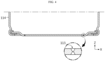
- FIG. 4 is a partial cross-sectional view schematically showing parts of a battery cell of the battery module according to an embodiment of the present disclosure.
- FIG. 5 is a partial cross-sectional view schematically showing the battery module according to an embodiment of the present disclosure.
- the X axis direction is the left direction
- the Y axis direction is the rear direction
- the Z axis direction is the upward direction.
- the battery module 100 includes a plurality of battery cells 110 and a cooling device 120.
- the cooling device 120 may be a device for cooling the plurality of battery cells 110.
- the plurality of battery cells 110 may be mounted on one side of the cooling device 120.
- the cooling device 120 may be configured to cool the plurality of battery cells 110 by the conduction of heat generated from the plurality of battery cells 110 mounted on one side.
- the cooling device 120 may contain a cooling medium 123 therein.
- the cooling device 120 may be configured to feed the chilled cooling medium into the body from the outside and release the heated cooling medium to the outside.
- the battery cell 110 may be a can-type secondary battery.
- the battery cell 110 may be a cylindrical battery cell or a prismatic battery cell.
- the cylindrical battery cell is taken as an example.
- the battery cell 110 may include a cylindrical battery can 114.
- the battery cell 110 may include both a positive electrode terminal 111 and a negative electrode terminal 112 on top of the battery can 114.
- an electrical insulating member may be interposed between the positive electrode terminal 111 and the negative electrode terminal 112. That is, the electrical insulating member may prevent the electrical connection between the positive electrode terminal 111 and the negative electrode terminal 112.
- the plurality of battery cells 110 may be arranged, for example, at a predetermined interval of 3 to 5 mm. Additionally, the plurality of battery cells 110 in a row and the plurality of battery cells 110 in another row may be disposed at different positions in the anterior-posterior direction (X axis direction in FIG. 1 ). Additionally, the plurality of battery cells 110 in a column and the plurality of battery cells 110 in another column may be disposed at different positions in the left-right direction (Y axis direction in FIG. 1 ). That is, the plurality of battery cells 110 may be arranged in a zigzag pattern in the front, rear, left and right directions as a whole. This arrangement may increase the integration density of the battery cells 110.
- the battery module 100 of the present disclosure may include the plurality of battery cells 110 electrically connected, for example, through a busbar or an electrical wire. That is, the battery module 100 of the present disclosure may include the plurality of battery cells 110 electrically connected by the contact of the positive electrode terminal 111 and the negative electrode terminal 112 of each of the plurality of battery cells 110 with the busbar or the electrical wire.
- the plurality of battery cells 110 may be, at the bottom, fixed to the cooling device 120 by heat fusion. That is, the cooling device 120 may have a bottom cooling structure.
- the cooling device 120 may include a battery cell mount portion 121 configured such that part of the battery cell mount portion 121 that contacts the battery cell 110 ruptures when at least one of gas or flame P is vented from the battery cell 110.
- the battery cell mount portion 121 may be configured such that part of the battery cell mount portion 121 that contacts the battery cell 110 ruptures by at least one of the gas or flame.
- the battery cell mount portion 121 may rupture as it melts away or is partially torn apart by at least one of the vented gas or flame.
- at least one of the gas or flame vented from the battery cell 110 may move in a direction opposite the direction in which the plurality of battery cells 110 is mounted through an opening O in the battery cell mount portion 121.
- the present disclosure since the present disclosure includes the battery cell mount portion 121 on which the plurality of battery cells 110 is mounted on at least one surface and configured such that part of the battery cell mount portion 121 that contacts the battery cell 110 ruptures when at least one of gas or flame is vented from the battery cell 110, it is possible to prevent a vent 113 through which the gas or flame from the battery cell 110 is vented from being trapped by the cooling device 120, and allow the gas or flame out through the opening O of the cooling member. Accordingly, as opposed to the conventional art, the present disclosure may prevent high temperature gas and flame from being vented from the side of the battery cell 110 due to the side rupture of the battery cell 110 by the trapped gas or flame.
- the cooling device 120 does not block the vent 113 of the battery cell 110, and when flame is vented through the vent 113 of the battery cell 110, the cooling device 120 easily ruptures. It is possible to prevent flame venting by the side rupture of the battery cell 110 and prevent fire propagation caused by the direct exposure of the neighboring battery cells to the flame. Since the cooling device 120 acts as a primary barrier when a fire occurs in any one battery cell 110, it is possible to effectively prevent the propagation of the fire to the other battery cell 110.
- the vent 113 makes it easy for the cooling device 120 to rupture in the event of a fire in the battery cell 110, thereby effectively venting the gas or flame from the battery cell 110 through the vent 113. Since the neighboring other battery cells 110 adjacent to the vented battery cell 110 are protected through the cooling device 120, it is possible to prevent the direct contact of the flame vented through the venting in the cell in which the fire occurred with the neighboring battery cells 110, thereby ensuring the safety.
- the vent 113 since the vent 113 is disposed at the bottom of the battery cell 110 and the cooling device 120 is below the battery cell 110, when overheat or a fire occurs due to an abnormal situation of the battery cell 110, the vent 113 allows gas or flame to be vented through the bottom of the battery module 100, not the top or the side of the battery module 100.
- the battery module 100 is provided in a vehicle, in general, a driver or passenger's seat is above the battery module 100, so it is possible to ensure the safety of the passenger to the maximum extent through the guidance of the gas or flame to the bottom of the battery module 100.
- the battery cell 110 may be a cylindrical battery cell as mentioned above, especially, for example, a cylindrical battery cell with the form factor ratio (defined as the product of dividing the diameter of the cylindrical battery cell by its height, i.e., a height (H)-to-diameter ( ⁇ ) ratio) of more than about 0.4.
- the form factor refers to a value indicating the diameter and height of the cylindrical battery cell.
- the cylindrical battery cell according to an embodiment of the present disclosure may be, for example, 46110 cell, 48750 cell, 48110 cell, 48800 cell and 46800 cell.
- the first two numbers indicate the diameter of the cell
- the next two numbers indicate the height of the cell
- the last number 0 indicates that the cross section of the cell is circular.
- the conventional battery module includes battery cells with the form factor of about 0.4 or less. For example, 1865 cell and 2170 cell have been used.
- the battery cell 110 included in the battery module 100 of the present disclosure is a large-scale battery cell. Accordingly, the battery module 100 of the present disclosure is more suitable for high capacity and high output.
- the improved cooling device 120 makes the battery module 100 of the present disclosure especially suitable as an automobile battery module requiring high capacity and high output.
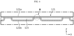
- FIG. 6 is a partial cross-sectional view schematically showing parts of the cooling device according to an embodiment of the present disclosure. Additionally, FIG. 7 is a partial enlarged cross-sectional view of section A in the cooling device of FIG. 6 .
- the battery cell mount portion 121 may include at least one layer configured such that part of one surface of the layer ruptures by at least one of gas or flame.
- the at least one layer of the battery cell mount portion 121 may include a multilayer film having a thickness of 10 ⁇ m to 900 ⁇ m.
- the at least one layer of the battery cell mount portion 121 may include an outer protective layer 122a, a reinforcement metal layer 122b and a first inner adhesive layer 122c1.
- the outer protective layer 122a may be on one surface of the reinforcement metal layer 122b and include a polymer resin having insulation properties.
- the insulating polymer resin of the outer protective layer 122a may include at least one selected from the group consisting of polyethylene, polypropylene, polyester, polyethylene terephthalate (PET), nylon, vinyl chloride, polyimide and polyphenylene sulfide.
- the outer protective layer 122a may be made of an abrasion resistant material.
- the reinforcement metal layer 122b may include at least one selected from the group consisting of copper (Cu), aluminum (Al), nickel (Ni), iron (Fe), carbon (C), chrome (Cr), manganese (Mn), stainless steel (SUS) and an alloy including at least two of them. Additionally, the thickness of the reinforcement metal layer 122b ranges from 1 ⁇ m to 100 ⁇ m. Additionally, the first inner adhesive layer 122c1 may include a pressure sensitive adhesive substance or a hot melt polymer resin. Here, the pressure sensitive adhesive substance may include at least one selected from the group consisting of an acrylic adhesive compound, a rubber-based adhesive compound, a silicone-based adhesive compound and a vinyl ether-based adhesive compound. The first inner adhesive layer 122c1 may be, for example, a cast polypropylene (CPP) film.
- CPP cast polypropylene
- the layer of the battery cell mount portion 121 may be the film having the thickness of 10 ⁇ m to 900 ⁇ m.
- the cooling device 120 formed of the film may be defined as a 'thin film' cooling device compared to the conventional cooling device using Al plates having the thickness of a few mm.
- the conventional cooling device including Al plate-Al plate, each having the thickness of a few mm, does not rupture by gas or flame vented from the battery cell.
- the layer of the battery cell mount portion 121 is the multilayer film having the above-described thickness, compared to the conventional cooling device, the cooling device of the present disclosure easily ruptures by gas or flame vented from the battery cell 110.
- the battery cell mount portion 121 is the film having the thickness of 10 ⁇ m to 900 ⁇ m, it is lighter than the conventional Al plate having the thickness of a few mm. Accordingly, it is possible to further reduce the thickness and weight of the battery module 100 including the cooling device 120 and increase the energy density per volume and the energy density per weight.
- the battery cell mount portion 121 may include the at least one layer.
- the battery cell mount portion 121 may include an upper plate 121a and a lower plate 121b.
- the plurality of battery cells 110 is mounted on one surface of the upper plate 121a.
- the upper plate 121a may have a plate shape of a predetermined size enough to mount the plurality of battery cells 110 on one surface (the upper surface).
- the said surface of the upper plate 121a may be flat.
- the upper plate 121a may include a structure such as protrusions to define the location at which each battery cell 110 is mounted.
- the lower plate 121b may be bonded to the other surface on which the plurality of battery cells 110 of the upper plate 121a is not mounted.
- the lower plate 121b may have an upper surface corresponding to the in-plane size of the upper plate 121a. That is, the lower plate 121b may have an outer periphery corresponding to the outer periphery of the upper plate 121a.
- the upper plate 121a may include at least one layer. Additionally, the lower plate 121b may include at least one layer.
- the upper plate 121a may have a triple layer stack configuration in the vertical direction, including an outer protective layer 122a at the top, a reinforcement metal layer 122b in the middle and a first inner adhesive layer 122c1 at the bottom.
- the lower plate 121b may have a triple layer stack configuration in the vertical direction, including a second inner adhesive layer 122c2 at the top, a reinforcement metal layer 122b in the middle and an outer protective layer 122a at the bottom.
- the first inner adhesive layer 122c1 of the upper plate 121a and the second inner adhesive layer 122c2 of the lower plate 121b may be bonded to each other.
- each of the two adhesive layers 122c1, 122c2 may include a hot melt polymer resin.
- the two adhesive layers may be fusion bonded to each other.
- the outer periphery of the lower plate 121b and the outer periphery of the upper plate 121a may be fusion bonded to each other.
- CPP films are used for the two adhesive layers 122c1, 122c2 they are melted to form a hermetic seal when heated.
- the lower plate 121b may have ridges protruding toward the upper plate 121a in cross section.
- the ridge protruding toward the upper plate 121a may be the upper surface of each of the wall of the lower plate 121b and the outer periphery of the lower plate 121b.
- the outer periphery of the upper plate 121a and the outer periphery of the lower plate 121b may be fusion bonded to each other.
- the present disclosure may reduce the number of components and shorten the manufacturing time, thereby reducing the manufacturing cost. Additionally, since the outer periphery of the upper plate 121a and the outer periphery of the lower plate 121b are fusion bonded to each other, the bond strength between them may be further increased. Accordingly, the present disclosure may prevent the cooling medium 123 from leaking through the gap between the upper plate 121a and the lower plate 121b due to cracking in the cooling device 120 when external impacts occur during the use of the battery module 100.
- FIG. 8 is a bottom perspective view schematically showing a coolant inlet port of the cooling device according to an embodiment of the present disclosure.
- the cooling device 120 may include the cooling medium 123, a coolant channel 124, a coolant inlet port 125 and a coolant outlet port 126.
- the cooling medium 123 may be, for example, water.
- the coolant channel 124 may be a passage along which the cooling medium 123 flows in the internal space of the battery cell mount portion 121.
- the coolant channel 124 may be a gap between the upper plate 121a and the lower plate 121b.
- the coolant channel 124 may be equipped in the lower plate 121b.
- the coolant channel 124 is an empty space protruding downward to allow the coolant to flow.
- the lower plate 121b may include walls protruding upward from the bottom of the coolant channel 124 to form the empty space.
- the coolant inlet port 125 may be in communication with the coolant channel 124 to feed the flow of the chilled cooling medium 123 into the body from the outside.
- the coolant inlet port 125 may be disposed at the front end of the battery cell mount portion 121.
- the coolant outlet port 126 may be in communication with the coolant channel 124 to allow the heated cooling medium 123 to exit.
- the coolant outlet port 126 may be disposed, for example, at the rear end of the battery cell mount portion 121.
- each of the coolant inlet port 125 and the coolant outlet port 126 may have a third adhesive layer 122c3 on the outer side thereof, and the third adhesive layer 122c3 may be bonded to the inner surface of the battery cell mount portion 121.
- the third adhesive layer 122c3 may include a pressure sensitive adhesive substance or a hot melt polymer resin.
- the third adhesive layer 122c3 may be the same as a third adhesive layer 122c3 of the battery cell mount portion 121.
- the third adhesive layer 122c3 of each of the coolant inlet port 125 and the coolant outlet port 126 and the third adhesive layer 122c3 of the battery cell mount portion 121 may be bonded to each other.
- the cooling device 120 of the present disclosure since the cooling device 120 of the present disclosure includes the upper plate 121a on which the plurality of battery cells 110 is mounted and the lower plate 121b bonded to the upper plate 121a, it is possible to bring the plurality of battery cells 110 into direct contact with the upper surface of the cooling device 120 without an addition of a heat conduction member interposed between, thereby increasing the cooling efficiency.
- each of the coolant inlet port 125 and the coolant outlet port 126 has the third adhesive layer 122c3 on the outer side thereof and the third adhesive layer 122c3 is bonded to the inner surface of the battery cell mount portion 121, it is possible to easily bond the third adhesive layer 122c3 of each of the coolant inlet port 125 and the coolant outlet port 126 and the third adhesive layer 122c3 of the battery cell mount portion 121 together.
- FIG. 9 is a plan view schematically showing a cooling device according to another embodiment of the present disclosure.
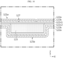
- FIG. 10 is a cross-sectional view of FIG. 9 taken along the line X-X'.
- the cooling device 120 may be the same as the cooling device 120 of FIG. 2 , except a notch 127.
- the battery cell mount 121 may have the notch 127 at part of the battery cell mount portion 121 that contacts the battery cell 110, and the notch 127 may tear apart by at least one of gas or flame.
- the notch 127 at the part of the battery cell mount portion 121 may be thinner than the remaining part of the battery cell mount portion 121.
- the notch 127 may tear apart by gas or flame vented from the battery cell 110 more easily than the remaining part of the battery cell mount portion 121. For example, as shown in FIG.
- the battery cell mount portion 121 of the cooling device 120 may have the notch 127 at part of the battery cell mount portion 121 that contacts each of the plurality of battery cells 110.
- the notch 127 may have a ring shape that is concentric with the battery cell 110 and has a smaller diameter than the battery cell 110.
- the notch 127 may be formed by reducing the thickness of part of the reinforcement metal layer 122b.
- the notch 127 may be formed in the multilayer thin film including the outer protective layer 122a, the reinforcement metal layer 122b and the first inner adhesive layer 122c1, and may be formed by reducing the thickness less than the remaining part by pressing or drilling parts of the outer protective layer 122a and the reinforcement metal layer 122b.
- the present disclosure since the present disclosure includes the notch 127 configured to tear apart by at least one of gas or flame at the part that contacts the battery cell 110, part of the battery cell mount portion 121 may rupture with higher reliability through the notch 127. Accordingly, the present disclosure may prevent the vent 113 (as described below) through which gas or flame from the battery cell 110 is vented from being blocked by the cooling device 120, and allow the gas or flame out through the opening of the cooling member ripped open. Accordingly, the present disclosure may significantly increase the safety of the battery module 100.
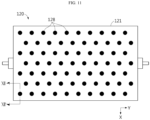
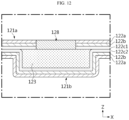
- FIG. 11 is a plan view schematically showing a cooling device according to still another embodiment of the present disclosure.
- FIG. 12 is a cross-sectional view of FIG. 11 taken along the line XII-XII'.
- the cooling device 120 according to still another embodiment of the present disclosure may be the same as the cooling device 120 of FIG. 2 , except an opening 128.
- the battery cell mount portion 121 may have the opening 128 configured to melt by at least one of gas or the flame at part of the battery cell mount portion 121 that contacts the battery cell 110.
- the opening 128 may have a circular shape that is concentric with the battery cell 110 and has a smaller diameter than the battery cell 110.
- the opening 128 may include, for example, a polymer resin having insulation properties and thermoplastic properties.
- the opening 128 may include at least one of polyethylene, polyethylene terephthalate, polyvinyl chloride, polyvinylidene chloride, polystyrene or polypropylene.
- the opening 128 may be formed by forming a hole in the upper plate 121a and filling the hole with the polymer resin having insulation properties and thermoplastic properties.
- FIG. 13 is another cross-sectional view of FIG. 11 taken along the line XII-XII'.
- the opening 128 may be formed without forming a hole in the upper plate 121a.
- the opening 128 may be formed by punching the reinforcement metal layer 122b.
- the outer protective layer 122a covers the punched reinforcement metal layer 122b, but since the outer protective layer 122a can melt well, the upper plate 121a easily ruptures compared to the unpunched reinforcement metal layer 122b.
- the present disclosure further includes the opening 128 configured to melt by at least one of gas or flame at the part that contacts the battery cell 110, when at least one of the gas or flame is vented from the battery cell 110, part of the battery cell mount portion 121 may rupture with high reliability through the opening 128 configured to melt by the gas or flame. Accordingly, the present disclosure prevents the vent 113 through which the gas or flame from the battery cell 110 is vented from being blocked by the cooling device 120 and allow the gas or flame out through the opening of the cooling member ripped open. Accordingly, the present disclosure may significantly improve the safety of the battery module 100.
- the battery module 100 includes the cooling device 120 and the plurality of battery cells 110.
- the battery cell 110 may be mounted on at least one surface of the battery cell mount portion 121 of the cooling device 120.
- the cooling device 120 may be fusion bonded to the bottom of the battery cell 110.
- the battery cell 110 may include the vent 113 at part that contacts the cooling device 120 to transport gas or flame within the body toward the cooling device 120 when abnormal behavior of the battery cell 110 occurs.
- the vent 113 may be the part of the battery can 114 having lower mechanical strength than the other part.
- the battery cell 110 may include the vent 113 at the bottom.
- the vent 113 may be where part of the bottom of the battery can 114 is thinner.
- the vent 113 may have a ring shape on the bottom.
- the vent 113 may be in the shape of an opening or a notch having a predetermined size.
- the vent 113 may further include a film in the opening of the predetermined size and the film ruptures under the pressure of the predetermined level or above.
- the present disclosure since the present disclosure includes the vent 113 at the part that contacts the cooling device 120 to vent the gas or flame within the body when abnormal behavior of the battery cell 110 occurs, it is possible to prevent the gas and flame vented from the battery cell 110 from moving to the adjacent other battery cell 110 and allow the gas and flame out through the opening of the battery cell mount portion 121 of the cooling device 120 ripped open, thereby preventing thermal runaway or a fire in the other battery cell 110. Accordingly, it is possible to greatly increase the safety of the battery module 100.
- FIG. 14 is a bottom perspective view schematically showing a battery module according to another embodiment of the present disclosure. Additionally, FIG. 15 is a partial cross-sectional view schematically showing parts of the battery module of FIG. 14 .
- the battery module 100 may have the same configuration as the battery module 100 of FIG. 1 , except the position of the plurality of battery cells 110 and the cooling device 120.
- the battery module 100 of FIG. 14 may include the cooling device 120 on the plurality of battery cells 110. Additionally, the plurality of battery cells 110 may be positioned upside down. That is, as opposed to the battery module 100 of FIG. 1 , each of the plurality of battery cells 110 may include the vent 113 at the top and the positive electrode terminal 111 and the negative electrode terminal 112 at the bottom. Additionally, the lower surface of the cooling device 120 of the battery module 100 of FIG. 14 may be in contact with the vent 113 of each of the plurality of battery cells 110.
- the cooling device 120 may be configured to release the cooling medium 123 from inside to outside through the ruptured part of the battery cell mount portion 121. That is, when at least one of gas or flame is vented through the vent 113 due to abnormal behavior of at least one of battery cells 110, the part of the battery cell mount portion 121 of the cooling device 120 may rupture, and the cooling medium 123 contained in the cooling device 120 may be released through the opening O. The released cooling medium 123 may move to the plurality of battery cells 110 to directly cool the plurality of battery cells 110.
- each of the plurality of battery cells 110 is mounted in contact with the lower surface of the cooling device 120 and the vent 113 is placed in contact with the cooling device 120, when at least one of gas or flame is vented through the vent 113 in the event of abnormal behavior of at least one of battery cells 110, part of the battery cell mount portion 121 of the cooling device 120 may rupture, and the cooling medium 123 contained in the cooling device 120 may be released through the opening O. Since the released cooling medium 123 moves to the plurality of battery cells 110 to directly cool the plurality of battery cells 110, it is possible to stop a fire in the battery module 100 and prevent the spread of thermal runaway to the plurality of battery cells 110.
- FIG. 16 is a diagram schematically showing a vehicle according to an embodiment of the present disclosure.
- the battery module 100 may be included in the vehicle 200 such as an electric vehicle or a hybrid electric vehicle. That is, the vehicle 200 according to an embodiment of the present disclosure may include the battery module 100 mounted in the vehicle body.
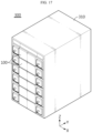
- FIG. 17 is a perspective view schematically showing an energy storage system according to an embodiment of the present disclosure.
- a battery rack 300 of the present disclosure includes a plurality of battery modules 100 and a rack case 310.
- the plurality of battery modules 100 may be vertically arranged and received in the rack case 310.
Landscapes
- Chemical & Material Sciences (AREA)
- Chemical Kinetics & Catalysis (AREA)
- Electrochemistry (AREA)
- General Chemical & Material Sciences (AREA)
- Engineering & Computer Science (AREA)
- Manufacturing & Machinery (AREA)
- Inorganic Chemistry (AREA)
- Aviation & Aerospace Engineering (AREA)
- Battery Mounting, Suspending (AREA)
- Secondary Cells (AREA)
- Gas Exhaust Devices For Batteries (AREA)
Abstract
Description
- The present disclosure relates to a cooling device, a battery module and an energy storage system and a vehicle comprising the battery module, and more particularly, to a cooling device for minimizing the spread of gas and flame vented from at least one of battery cells to adjacent other battery cells.
- The present application claims priority to
Korean Patent Application No. 10-2021-0069517 filed on May 28, 2021 - Currently, commercially available secondary batteries include nickel-cadmium batteries, nickel-hydrogen batteries, nickel-zinc batteries, lithium secondary batteries and the like, and among them, lithium secondary batteries have little or no memory effect, and thus they are gaining more attention than nickel-based secondary batteries for their advantages that recharging can be done whenever it is convenient, the self-discharge rate is very low and the energy density is high.
- In the lithium secondary batteries, a lithium-based oxide and a carbon material are primarily used for a positive electrode active material and a negative electrode active material, respectively. The lithium secondary battery includes an electrode assembly including a positive electrode plate and a negative electrode plate coated with the positive electrode active material and the negative electrode active material, respectively, with a separator interposed between the positive electrode plate and the negative electrode plate, and a packaging or a battery pouch packaging in which the electrode assembly is hermetically received together with an electrolyte solution.
- Recently, secondary batteries are widely used in not only small devices such as mobile electronic devices but also small- and medium-sized devices such as vehicles or energy storage systems (ESSs). In the small- and medium-sized device applications, a plurality of secondary batteries is electrically connected to increase the capacity and output.
- More recently, with the widespread use as an energy storage source and the growing need for high capacity structure, battery modules include a plurality of battery cells arranged with high density.
- In the plurality of battery cells arranged with high density, it is necessary to cool the plurality of battery cells to effectively dissipate heat. Accordingly, the conventional battery module includes a cooling device to cool the plurality of battery cells. Additionally, in some cases, the cooling device equipped in the battery module is placed in direct contact with at least some of the battery cells to increase the heat conduction efficiency. Additionally, each of the plurality of battery cells in the conventional battery module includes a vent to release high temperature gas and flame from the battery cell in the event of thermal runaway or a fire in the battery cell.
- However, in case that the vent of the battery cell is supported or blocked by the cooling device, high temperature gas and flame cannot exit the battery cell through the vent in the event of thermal runaway or a fire in the battery cell. For example, the conventional cooling device including Al plate-Al plate brazed together, each having the thickness of a few mm, blocks the vent of the battery cell. The gas and flame trapped in the battery cell increases the internal pressure of the battery cell, and any other part (the side) of the battery cell may rupture, causing gas and flame leaks. The leaking gas and flame is not directed in the intended direction of the vent and directly moves to the adjacent other battery cell, causing thermal runaway or a fire in the other battery cell. It significantly reduces the safety of the battery module.
- The present disclosure is designed to solve the above-described problem, and therefore the present disclosure is directed to providing a cooling device for minimizing the spread of gas and flame vented from at least one of battery cells to the adjacent other battery cell, a battery module, and an energy storage system and a vehicle comprising the battery module.
- These and other objectives and advantages of the present disclosure can be understood by the following description and will be clearly described by the embodiments of the present disclosure. In addition, it will be readily appreciated that the objectives and advantages of the present disclosure can be realized by the means set forth in the appended claims and a combination thereof.
- To achieve the above-described objective, a cooling device according to the present disclosure is a cooling device for cooling a plurality of battery cells, and includes a battery cell mount portion on which the plurality of battery cells is mounted on at least one surface, wherein a part of the battery cell mount portion that contacts the battery cell is configured to rupture when at least one of gas or flame is vented from the battery cell.
- Additionally, the battery cell mount portion may include at least one layer configured such that a part of one surface ruptures by at least one of the gas or flame.
- The battery cell mount portion may include an upper plate on which the plurality of battery cells is mounted on a surface and a lower plate bonded to an opposite surface of the upper plate, and each of the upper plate and the lower plate may include a multilayer film having a thickness of 10 µm to 900 µm.
- The multilayer film may include an outer protective layer, a reinforcement metal layer and an inner adhesive layer.
- The outer protective layer may include a polymer resin having insulation properties, the metal layer may include at least one selected from the group consisting of copper (Cu), aluminum (Al), nickel (Ni), iron (Fe), carbon (C), chrome (Cr), manganese (Mn), stainless steel (SUS) and an alloy including at least two of them, and the inner adhesive layer may include a pressure sensitive adhesive substance or a hot melt polymer resin.
- The reinforcement metal layer may have a thickness ranging from 1 µm to 100 µm.
- Furthermore, the cooling device may include a coolant channel along which a cooling medium flows in the battery cell mount portion; a coolant inlet port in communication with the coolant channel, the coolant inlet port through which the cooling medium enters; and a coolant outlet port in communication with the coolant channel, the coolant outlet port through which the cooling medium exits, each of the coolant inlet port and the coolant outlet port may have an adhesive layer on an outer side, and the adhesive layer may be bonded to an inner surface of the battery cell mount portion.
- In this instance, the battery cell mount portion may include an upper plate on which the plurality of battery cells is mounted on a surface, and a lower plate bonded to an opposite surface of the upper plate, each of the upper plate and the lower plate may include an outer protective layer, a reinforcement metal layer and an inner adhesive layer, and the inner adhesive layer of the upper plate and the inner adhesive layer of the lower plate may be bonded to each other.
- Additionally, the battery cell mount portion may have a notch configured to tear apart by at least one of the gas or flame at the part that contacts the battery cell.
- The battery cell may be a cylindrical battery cell, and the notch may have a ring shape which is concentric with the battery cell and has a smaller diameter than the battery cell.
- The battery cell mount portion may include an upper plate on which the plurality of battery cells is mounted on a surface and a lower plate bonded to an opposite surface of the upper plate, each of the upper plate and the lower plate may include an outer protective layer, a reinforcement metal layer and an inner adhesive layer, and the notch may be formed by reducing a thickness of part of the reinforcement metal layer.
- Furthermore, the battery cell mount portion may have an opening configured to melt by at least one of the gas or flame at the part that contacts the battery cell.
- The battery cell may be a cylindrical battery cell, and the opening may have a circular shape which is concentric with the battery cell and has a smaller diameter than the battery cell.
- The battery cell mount portion may include an upper plate on which the plurality of battery cells is mounted on a surface and a lower plate bonded to an opposite surface of the upper plate, each of the upper plate and the lower plate may include an outer protective layer, a reinforcement metal layer and an inner adhesive layer, and the opening may be formed by punching the reinforcement metal layer.
- In addition, to achieve the above-described objective, a battery module according to the present disclosure includes the cooling device according to the present disclosure; and a plurality of battery cells mounted on at least one surface of the battery cell mount portion of the cooling device.
- Additionally, the battery cell may include a vent at a part of the battery cell that contacts the cooling device, the vent configured to vent gas or flame within a body toward the cooling device when abnormal behavior of the battery cell occurs.
- Additionally, the cooling device may be disposed on the plurality of battery cells, each of the plurality of battery cells may be mounted in contact with a lower surface of the cooling device, and the vent may be disposed in contact with the cooling device.
- Further, the cooling device may be configured to release a cooling medium within the cooling device through the ruptured part of the battery cell mount portion.
- In a preferred embodiment, the battery cell is a cylindrical battery cell with the vent on bottom, the vent configured to vent the gas or flame within a body toward the cooling device when abnormal behavior of the battery cell occurs, and the cooling device is fusion bonded to a bottom of the battery cell.
- The cooling medium within the cooling device is water, and the cooling medium is fed into the vented battery cell through the ruptured part of the battery cell mount portion.
- In addition, to achieve the above-described objective, an energy storage system of the present disclosure includes the battery module.
- Furthermore, to achieve the above-described objective, a vehicle of the present disclosure includes the battery module.
- According to an aspect of the present disclosure, since the present disclosure includes the battery cell mount portion on which the plurality of battery cells is mounted on at least one surface, and configured such that part of the battery cell mount portion that contacts the battery cell ruptures when at least one of gas or flame is vented from the battery cell, it is possible to prevent the vent through which gas or flame is vented from the battery cell from being blocked by the cooling device and allow the gas or flame out through the opening of the cooling member ripped open.
- Accordingly, as opposed to the conventional art, the present disclosure may prevent high temperature gas and flame from being vented from the side of the battery cell due to the side rupture of the battery cell by the trapped gas or flame. Accordingly, it is possible to prevent the gas and flame vented from the battery cell from moving to the adjacent other battery cell, thereby preventing thermal runaway or a fire in the other battery cell. Accordingly, it is possible to greatly increase the safety of the battery module.
- In particular, when the battery cell has the vent, the vent makes it easy for the cooling device to rupture in the event of a fire in the battery cell, thereby effectively venting the gas or flame from the battery cell through the vent. Since the neighboring battery cells adjacent to the vented battery cell are protected through the cooling device, it is possible to prevent the direct contact of the flame vented through venting in the cell in which the fire occurred with the neighboring battery cells, thereby ensuring the safety.
- According to another aspect of the present disclosure, since the present disclosure includes the upper plate on which the plurality of battery cells is mounted and the lower plate bonded to the upper plate, it is possible to bring the plurality of battery cells into direct contact with the cooling device without an addition of a heat conduction member interposed between, thereby increasing the cooling efficiency. Since each of the upper plate and the lower plate includes a multilayer film having a thickness of 10 µm to 900 µm, it is possible to easily rupture by gas or flame vented from the battery cell compared to the conventional cooling device including Al plate-Al plate, each having the thickness of a few mm.
- According to another aspect of the present disclosure, since the lower plate of the cooling device is fusion bonded to the other surface of the upper plate, it is possible to perform the assembly process of the cooling device without any fastening member. Accordingly, compared to the conventional art, the present disclosure may reduce the number of components and shorten the manufacturing time, thereby reducing the manufacturing cost.
- Additionally, according to another aspect of the present disclosure, since the outer periphery of the upper plate and the outer periphery of the lower plate are fusion bonded to each other, the present disclosure may further increase the bond strength between them. Accordingly, the present disclosure may prevent the cooling medium from leaking through a gap between the upper plate and the lower plate due to cracking in the cooling device when external impacts occur during the use of the battery module.
- The accompanying drawings illustrate the exemplary embodiment of the present disclosure and together with the following detailed description, serve to provide further understanding of the technical features of the present disclosure, and thus, the present disclosure should not be construed as being limited to the drawings.
-
FIG. 1 is a perspective view schematically showing a battery module according to an embodiment of the present disclosure. -
FIG. 2 is a perspective view schematically showing a cooling device according to an embodiment of the present disclosure. -
FIG. 3 is a bottom perspective view schematically showing a cooling device according to an embodiment of the present disclosure. -
FIG. 4 is a partial cross-sectional view schematically showing parts of a battery cell of a battery module according to an embodiment of the present disclosure. -
FIG. 5 is a partial cross-sectional view schematically showing a battery module according to an embodiment of the present disclosure. -
FIG. 6 is a partial cross-sectional view schematically showing parts of a cooling device according to an embodiment of the present disclosure. -
FIG. 7 is a partial enlarged cross-sectional view of section A in the cooling device ofFIG. 6 . -
FIG. 8 is a bottom perspective view schematically showing a coolant inlet port of a cooling device according to an embodiment of the present disclosure. -
FIG. 9 is a plan view schematically showing a cooling device according to another embodiment of the present disclosure. -
FIG. 10 is a cross-sectional view ofFIG. 9 taken along the line X-X'. -
FIG. 11 is a plan view schematically showing a cooling device according to still another embodiment of the present disclosure. -
FIG. 12 is a cross-sectional view ofFIG. 11 taken along the line XII-XII'. -
FIG. 13 is another cross-sectional view ofFIG. 11 taken along the line XII-XII'. -
FIG. 14 is a bottom perspective view schematically showing a battery module according to another embodiment of the present disclosure. -
FIG. 15 is a partial cross-sectional view schematically showing parts of the battery module ofFIG. 14 . -
FIG. 16 is a diagram schematically showing a vehicle according to an embodiment of the present disclosure. -
FIG. 17 is a perspective view schematically showing an energy storage system according to an embodiment of the present disclosure. - Hereinafter, the exemplary embodiments of the present disclosure will be described in detail with reference to the accompanying drawings. Prior to the description, it should be understood that the terms or words used in the specification and the appended claims should not be construed as being limited to general and dictionary meanings, but rather interpreted based on the meanings and concepts corresponding to the technical aspects of the present disclosure on the basis of the principle that the inventor is allowed to define the terms appropriately for the best explanation.
- Therefore, the embodiments described herein and the illustrations shown in the drawings are just an exemplary embodiment of the present disclosure, but not intended to fully describe the technical aspects of the present disclosure, so it should be understood that a variety of other equivalents and modifications could have been made thereto at the time that the application was filed.
-
FIG. 1 is a perspective view schematically showing a battery module according to an embodiment of the present disclosure.FIG. 2 is a perspective view schematically showing a cooling device according to an embodiment of the present disclosure.FIG. 3 is a bottom perspective view schematically showing the cooling device according to an embodiment of the present disclosure.FIG. 4 is a partial cross-sectional view schematically showing parts of a battery cell of the battery module according to an embodiment of the present disclosure. Additionally,FIG. 5 is a partial cross-sectional view schematically showing the battery module according to an embodiment of the present disclosure. For reference, inFIG. 1 , the X axis direction is the left direction, the Y axis direction is the rear direction, and the Z axis direction is the upward direction. - Referring to
FIGS. 1 to 5 , thebattery module 100 according to an embodiment of the present disclosure includes a plurality ofbattery cells 110 and acooling device 120. Thecooling device 120 according to an embodiment of the present disclosure may be a device for cooling the plurality ofbattery cells 110. The plurality ofbattery cells 110 may be mounted on one side of thecooling device 120. Thecooling device 120 may be configured to cool the plurality ofbattery cells 110 by the conduction of heat generated from the plurality ofbattery cells 110 mounted on one side. For example, thecooling device 120 may contain a cooling medium 123 therein. Alternatively, thecooling device 120 may be configured to feed the chilled cooling medium into the body from the outside and release the heated cooling medium to the outside. - Here, the
battery cell 110 may be a can-type secondary battery. For example, thebattery cell 110 may be a cylindrical battery cell or a prismatic battery cell. In this embodiment, the cylindrical battery cell is taken as an example. Thebattery cell 110 may include a cylindrical battery can 114. Thebattery cell 110 may include both apositive electrode terminal 111 and anegative electrode terminal 112 on top of the battery can 114. Although not shown in the drawing, for example, an electrical insulating member may be interposed between thepositive electrode terminal 111 and thenegative electrode terminal 112. That is, the electrical insulating member may prevent the electrical connection between thepositive electrode terminal 111 and thenegative electrode terminal 112. - The plurality of
battery cells 110 may be arranged, for example, at a predetermined interval of 3 to 5 mm. Additionally, the plurality ofbattery cells 110 in a row and the plurality ofbattery cells 110 in another row may be disposed at different positions in the anterior-posterior direction (X axis direction inFIG. 1 ). Additionally, the plurality ofbattery cells 110 in a column and the plurality ofbattery cells 110 in another column may be disposed at different positions in the left-right direction (Y axis direction inFIG. 1 ). That is, the plurality ofbattery cells 110 may be arranged in a zigzag pattern in the front, rear, left and right directions as a whole. This arrangement may increase the integration density of thebattery cells 110. - Additionally, although not shown, the
battery module 100 of the present disclosure may include the plurality ofbattery cells 110 electrically connected, for example, through a busbar or an electrical wire. That is, thebattery module 100 of the present disclosure may include the plurality ofbattery cells 110 electrically connected by the contact of thepositive electrode terminal 111 and thenegative electrode terminal 112 of each of the plurality ofbattery cells 110 with the busbar or the electrical wire. - The plurality of
battery cells 110 may be, at the bottom, fixed to thecooling device 120 by heat fusion. That is, thecooling device 120 may have a bottom cooling structure. - Additionally, the
cooling device 120 may include a batterycell mount portion 121 configured such that part of the batterycell mount portion 121 that contacts thebattery cell 110 ruptures when at least one of gas or flame P is vented from thebattery cell 110. Here, when abnormal behavior such as an internal short circuit or thermal runaway occurs, at least one of the gas or flame may be vented from thebattery cell 110. In this instance, the batterycell mount portion 121 may be configured such that part of the batterycell mount portion 121 that contacts thebattery cell 110 ruptures by at least one of the gas or flame. The batterycell mount portion 121 may rupture as it melts away or is partially torn apart by at least one of the vented gas or flame. In this instance, at least one of the gas or flame vented from thebattery cell 110 may move in a direction opposite the direction in which the plurality ofbattery cells 110 is mounted through an opening O in the batterycell mount portion 121. - According to this configuration of the present disclosure, since the present disclosure includes the battery
cell mount portion 121 on which the plurality ofbattery cells 110 is mounted on at least one surface and configured such that part of the batterycell mount portion 121 that contacts thebattery cell 110 ruptures when at least one of gas or flame is vented from thebattery cell 110, it is possible to prevent avent 113 through which the gas or flame from thebattery cell 110 is vented from being trapped by thecooling device 120, and allow the gas or flame out through the opening O of the cooling member. Accordingly, as opposed to the conventional art, the present disclosure may prevent high temperature gas and flame from being vented from the side of thebattery cell 110 due to the side rupture of thebattery cell 110 by the trapped gas or flame. Accordingly, it is possible to prevent the gas and flame vented from thebattery cell 110 from moving to the adjacentother battery cell 110, thereby preventing thermal runaway or fire in theother battery cell 110. Accordingly, it is possible to greatly increase the safety of thebattery module 100. That is, thecooling device 120 does not block thevent 113 of thebattery cell 110, and when flame is vented through thevent 113 of thebattery cell 110, thecooling device 120 easily ruptures. It is possible to prevent flame venting by the side rupture of thebattery cell 110 and prevent fire propagation caused by the direct exposure of the neighboring battery cells to the flame. Since thecooling device 120 acts as a primary barrier when a fire occurs in any onebattery cell 110, it is possible to effectively prevent the propagation of the fire to theother battery cell 110. - In particular, as shown in this embodiment, when the
battery cell 110 includes thevent 113 at the bottom thereof, thevent 113 makes it easy for thecooling device 120 to rupture in the event of a fire in thebattery cell 110, thereby effectively venting the gas or flame from thebattery cell 110 through thevent 113. Since the neighboringother battery cells 110 adjacent to the ventedbattery cell 110 are protected through thecooling device 120, it is possible to prevent the direct contact of the flame vented through the venting in the cell in which the fire occurred with the neighboringbattery cells 110, thereby ensuring the safety. - In this embodiment, since the
vent 113 is disposed at the bottom of thebattery cell 110 and thecooling device 120 is below thebattery cell 110, when overheat or a fire occurs due to an abnormal situation of thebattery cell 110, thevent 113 allows gas or flame to be vented through the bottom of thebattery module 100, not the top or the side of thebattery module 100. For example, when thebattery module 100 is provided in a vehicle, in general, a driver or passenger's seat is above thebattery module 100, so it is possible to ensure the safety of the passenger to the maximum extent through the guidance of the gas or flame to the bottom of thebattery module 100. - The
battery cell 110 may be a cylindrical battery cell as mentioned above, especially, for example, a cylindrical battery cell with the form factor ratio (defined as the product of dividing the diameter of the cylindrical battery cell by its height, i.e., a height (H)-to-diameter (Φ) ratio) of more than about 0.4. Here, the form factor refers to a value indicating the diameter and height of the cylindrical battery cell. The cylindrical battery cell according to an embodiment of the present disclosure may be, for example, 46110 cell, 48750 cell, 48110 cell, 48800 cell and 46800 cell. In the numbers indicating the form factor, the first two numbers indicate the diameter of the cell, the next two numbers indicate the height of the cell, and the last number 0 indicates that the cross section of the cell is circular. - The conventional battery module includes battery cells with the form factor of about 0.4 or less. For example, 1865 cell and 2170 cell have been used. In contrast, the
battery cell 110 included in thebattery module 100 of the present disclosure is a large-scale battery cell. Accordingly, thebattery module 100 of the present disclosure is more suitable for high capacity and high output. Additionally, theimproved cooling device 120 makes thebattery module 100 of the present disclosure especially suitable as an automobile battery module requiring high capacity and high output. -
FIG. 6 is a partial cross-sectional view schematically showing parts of the cooling device according to an embodiment of the present disclosure. Additionally,FIG. 7 is a partial enlarged cross-sectional view of section A in the cooling device ofFIG. 6 . - Referring to
FIGS. 6 and7 , the batterycell mount portion 121 may include at least one layer configured such that part of one surface of the layer ruptures by at least one of gas or flame. For example, the at least one layer of the batterycell mount portion 121 may include a multilayer film having a thickness of 10 µm to 900 µm. Preferably, the at least one layer of the batterycell mount portion 121 may include an outerprotective layer 122a, areinforcement metal layer 122b and a first inner adhesive layer 122c1. The outerprotective layer 122a may be on one surface of thereinforcement metal layer 122b and include a polymer resin having insulation properties. The insulating polymer resin of the outerprotective layer 122a may include at least one selected from the group consisting of polyethylene, polypropylene, polyester, polyethylene terephthalate (PET), nylon, vinyl chloride, polyimide and polyphenylene sulfide. The outerprotective layer 122a may be made of an abrasion resistant material. - The
reinforcement metal layer 122b may include at least one selected from the group consisting of copper (Cu), aluminum (Al), nickel (Ni), iron (Fe), carbon (C), chrome (Cr), manganese (Mn), stainless steel (SUS) and an alloy including at least two of them. Additionally, the thickness of thereinforcement metal layer 122b ranges from 1 µm to 100 µm. Additionally, the first inner adhesive layer 122c1 may include a pressure sensitive adhesive substance or a hot melt polymer resin. Here, the pressure sensitive adhesive substance may include at least one selected from the group consisting of an acrylic adhesive compound, a rubber-based adhesive compound, a silicone-based adhesive compound and a vinyl ether-based adhesive compound. The first inner adhesive layer 122c1 may be, for example, a cast polypropylene (CPP) film. - As described above, the layer of the battery
cell mount portion 121 may be the film having the thickness of 10 µm to 900 µm. Thecooling device 120 formed of the film may be defined as a 'thin film' cooling device compared to the conventional cooling device using Al plates having the thickness of a few mm. The conventional cooling device including Al plate-Al plate, each having the thickness of a few mm, does not rupture by gas or flame vented from the battery cell. When the layer of the batterycell mount portion 121 is the multilayer film having the above-described thickness, compared to the conventional cooling device, the cooling device of the present disclosure easily ruptures by gas or flame vented from thebattery cell 110. Additionally, since the batterycell mount portion 121 is the film having the thickness of 10 µm to 900 µm, it is lighter than the conventional Al plate having the thickness of a few mm. Accordingly, it is possible to further reduce the thickness and weight of thebattery module 100 including thecooling device 120 and increase the energy density per volume and the energy density per weight. - Additionally, as shown in
FIG. 6 , the batterycell mount portion 121 may include the at least one layer. For example, as shown inFIG. 7 , the batterycell mount portion 121 may include anupper plate 121a and alower plate 121b. The plurality ofbattery cells 110 is mounted on one surface of theupper plate 121a. For example, theupper plate 121a may have a plate shape of a predetermined size enough to mount the plurality ofbattery cells 110 on one surface (the upper surface). The said surface of theupper plate 121a may be flat. In another example, theupper plate 121a may include a structure such as protrusions to define the location at which eachbattery cell 110 is mounted. - The
lower plate 121b may be bonded to the other surface on which the plurality ofbattery cells 110 of theupper plate 121a is not mounted. Thelower plate 121b may have an upper surface corresponding to the in-plane size of theupper plate 121a. That is, thelower plate 121b may have an outer periphery corresponding to the outer periphery of theupper plate 121a. - The
upper plate 121a may include at least one layer. Additionally, thelower plate 121b may include at least one layer. For example, as shown inFIG. 7 , theupper plate 121a may have a triple layer stack configuration in the vertical direction, including an outerprotective layer 122a at the top, areinforcement metal layer 122b in the middle and a first inner adhesive layer 122c1 at the bottom. Thelower plate 121b may have a triple layer stack configuration in the vertical direction, including a second inner adhesive layer 122c2 at the top, areinforcement metal layer 122b in the middle and an outerprotective layer 122a at the bottom. In this instance, the first inner adhesive layer 122c1 of theupper plate 121a and the second inner adhesive layer 122c2 of thelower plate 121b may be bonded to each other. For example, each of the two adhesive layers 122c1, 122c2 may include a hot melt polymer resin. The two adhesive layers may be fusion bonded to each other. Accordingly, the outer periphery of thelower plate 121b and the outer periphery of theupper plate 121a may be fusion bonded to each other. For example, in case that CPP films are used for the two adhesive layers 122c1, 122c2, they are melted to form a hermetic seal when heated. - Referring further to
FIG. 6 , thelower plate 121b may have ridges protruding toward theupper plate 121a in cross section. Here, the ridge protruding toward theupper plate 121a may be the upper surface of each of the wall of thelower plate 121b and the outer periphery of thelower plate 121b. Further, the outer periphery of theupper plate 121a and the outer periphery of thelower plate 121b may be fusion bonded to each other. - Since the first inner adhesive layer 122c1 of the
upper plate 121a and the second inner adhesive layer 122c2 of thelower plate 121b are bonded to each other, it is possible to perform the assembly process of thecooling device 120 without any fastening member. Accordingly, compared to the conventional art, the present disclosure may reduce the number of components and shorten the manufacturing time, thereby reducing the manufacturing cost. Additionally, since the outer periphery of theupper plate 121a and the outer periphery of thelower plate 121b are fusion bonded to each other, the bond strength between them may be further increased. Accordingly, the present disclosure may prevent the cooling medium 123 from leaking through the gap between theupper plate 121a and thelower plate 121b due to cracking in thecooling device 120 when external impacts occur during the use of thebattery module 100. -
FIG. 8 is a bottom perspective view schematically showing a coolant inlet port of the cooling device according to an embodiment of the present disclosure. - Referring to
FIG. 8 together withFIGS. 1 , and2 , thecooling device 120 according to an embodiment of the present disclosure may include the cooling medium 123, acoolant channel 124, acoolant inlet port 125 and acoolant outlet port 126. Here, the cooling medium 123, may be, for example, water. - The
coolant channel 124 may be a passage along which the cooling medium 123 flows in the internal space of the batterycell mount portion 121. For example, thecoolant channel 124 may be a gap between theupper plate 121a and thelower plate 121b. Thecoolant channel 124 may be equipped in thelower plate 121b. Thecoolant channel 124 is an empty space protruding downward to allow the coolant to flow. Thelower plate 121b may include walls protruding upward from the bottom of thecoolant channel 124 to form the empty space. Thecoolant inlet port 125 may be in communication with thecoolant channel 124 to feed the flow of the chilled cooling medium 123 into the body from the outside. For example, thecoolant inlet port 125 may be disposed at the front end of the batterycell mount portion 121. Thecoolant outlet port 126 may be in communication with thecoolant channel 124 to allow theheated cooling medium 123 to exit. Thecoolant outlet port 126 may be disposed, for example, at the rear end of the batterycell mount portion 121. - Additionally, each of the
coolant inlet port 125 and thecoolant outlet port 126 may have a third adhesive layer 122c3 on the outer side thereof, and the third adhesive layer 122c3 may be bonded to the inner surface of the batterycell mount portion 121. The third adhesive layer 122c3 may include a pressure sensitive adhesive substance or a hot melt polymer resin. For example, the third adhesive layer 122c3 may be the same as a third adhesive layer 122c3 of the batterycell mount portion 121. The third adhesive layer 122c3 of each of thecoolant inlet port 125 and thecoolant outlet port 126 and the third adhesive layer 122c3 of the batterycell mount portion 121 may be bonded to each other. - According to this configuration of the present disclosure, since the
cooling device 120 of the present disclosure includes theupper plate 121a on which the plurality ofbattery cells 110 is mounted and thelower plate 121b bonded to theupper plate 121a, it is possible to bring the plurality ofbattery cells 110 into direct contact with the upper surface of thecooling device 120 without an addition of a heat conduction member interposed between, thereby increasing the cooling efficiency. - Additionally, since each of the
coolant inlet port 125 and thecoolant outlet port 126 has the third adhesive layer 122c3 on the outer side thereof and the third adhesive layer 122c3 is bonded to the inner surface of the batterycell mount portion 121, it is possible to easily bond the third adhesive layer 122c3 of each of thecoolant inlet port 125 and thecoolant outlet port 126 and the third adhesive layer 122c3 of the batterycell mount portion 121 together. Accordingly, it is possible to effectively increase the sealability at the connected part of each of thecoolant inlet port 125 and thecoolant outlet port 126 and thecoolant channel 124 of the batterycell mount portion 121, and since the bonding method between the port and the batterycell mount portion 121 is the same as the bonding method of the batterycell mount portion 121, it is possible to simplify the fabrication process of thecooling device 120, thereby greatly increasing the fabrication efficiency. -
FIG. 9 is a plan view schematically showing a cooling device according to another embodiment of the present disclosure.FIG. 10 is a cross-sectional view ofFIG. 9 taken along the line X-X'. - Referring to
FIGS. 9 and10 together withFIGS. 1 and4 , thecooling device 120 according to another embodiment of the present disclosure may be the same as thecooling device 120 ofFIG. 2 , except anotch 127. Thebattery cell mount 121 may have thenotch 127 at part of the batterycell mount portion 121 that contacts thebattery cell 110, and thenotch 127 may tear apart by at least one of gas or flame. Thenotch 127 at the part of the batterycell mount portion 121 may be thinner than the remaining part of the batterycell mount portion 121. Thenotch 127 may tear apart by gas or flame vented from thebattery cell 110 more easily than the remaining part of the batterycell mount portion 121. For example, as shown inFIG. 9 , the batterycell mount portion 121 of thecooling device 120 may have thenotch 127 at part of the batterycell mount portion 121 that contacts each of the plurality ofbattery cells 110. In particular, when thebattery cell 110 is a cylindrical battery cell, thenotch 127 may have a ring shape that is concentric with thebattery cell 110 and has a smaller diameter than thebattery cell 110. - Additionally, when the
upper plate 121a includes the outerprotective layer 122a, thereinforcement metal layer 122b and the first inner adhesive layer 122c1, thenotch 127 may be formed by reducing the thickness of part of thereinforcement metal layer 122b. Thenotch 127 may be formed in the multilayer thin film including the outerprotective layer 122a, thereinforcement metal layer 122b and the first inner adhesive layer 122c1, and may be formed by reducing the thickness less than the remaining part by pressing or drilling parts of the outerprotective layer 122a and thereinforcement metal layer 122b. - According to this configuration of the present disclosure, since the present disclosure includes the
notch 127 configured to tear apart by at least one of gas or flame at the part that contacts thebattery cell 110, part of the batterycell mount portion 121 may rupture with higher reliability through thenotch 127. Accordingly, the present disclosure may prevent the vent 113 (as described below) through which gas or flame from thebattery cell 110 is vented from being blocked by thecooling device 120, and allow the gas or flame out through the opening of the cooling member ripped open. Accordingly, the present disclosure may significantly increase the safety of thebattery module 100. -
FIG. 11 is a plan view schematically showing a cooling device according to still another embodiment of the present disclosure.FIG. 12 is a cross-sectional view ofFIG. 11 taken along the line XII-XII'. Referring toFIGS. 11 and12 together withFIGS. 1 and4 , thecooling device 120 according to still another embodiment of the present disclosure may be the same as thecooling device 120 ofFIG. 2 , except anopening 128. The batterycell mount portion 121 may have theopening 128 configured to melt by at least one of gas or the flame at part of the batterycell mount portion 121 that contacts thebattery cell 110. In particular, when thebattery cell 110 is a cylindrical battery cell, theopening 128 may have a circular shape that is concentric with thebattery cell 110 and has a smaller diameter than thebattery cell 110. Theopening 128 may include, for example, a polymer resin having insulation properties and thermoplastic properties. For example, theopening 128 may include at least one of polyethylene, polyethylene terephthalate, polyvinyl chloride, polyvinylidene chloride, polystyrene or polypropylene. Theopening 128 may be formed by forming a hole in theupper plate 121a and filling the hole with the polymer resin having insulation properties and thermoplastic properties. -
FIG. 13 is another cross-sectional view ofFIG. 11 taken along the line XII-XII'. Theopening 128 may be formed without forming a hole in theupper plate 121a. When theupper plate 121a includes the outerprotective layer 122a, thereinforcement metal layer 122b and the first inner adhesive layer 122c 1, theopening 128 may be formed by punching thereinforcement metal layer 122b. The outerprotective layer 122a covers the punchedreinforcement metal layer 122b, but since the outerprotective layer 122a can melt well, theupper plate 121a easily ruptures compared to the unpunchedreinforcement metal layer 122b. - According to this configuration of the present disclosure, since the present disclosure further includes the
opening 128 configured to melt by at least one of gas or flame at the part that contacts thebattery cell 110, when at least one of the gas or flame is vented from thebattery cell 110, part of the batterycell mount portion 121 may rupture with high reliability through theopening 128 configured to melt by the gas or flame. Accordingly, the present disclosure prevents thevent 113 through which the gas or flame from thebattery cell 110 is vented from being blocked by thecooling device 120 and allow the gas or flame out through the opening of the cooling member ripped open. Accordingly, the present disclosure may significantly improve the safety of thebattery module 100. - Referring back to
FIGS. 1 and4 , thebattery module 100 according to an embodiment of the present disclosure includes thecooling device 120 and the plurality ofbattery cells 110. Thebattery cell 110 may be mounted on at least one surface of the batterycell mount portion 121 of thecooling device 120. Thecooling device 120 may be fusion bonded to the bottom of thebattery cell 110. - Furthermore, the
battery cell 110 may include thevent 113 at part that contacts thecooling device 120 to transport gas or flame within the body toward thecooling device 120 when abnormal behavior of thebattery cell 110 occurs. For example, thevent 113 may be the part of the battery can 114 having lower mechanical strength than the other part. For example, as shown inFIG. 4 , thebattery cell 110 may include thevent 113 at the bottom. Thevent 113 may be where part of the bottom of the battery can 114 is thinner. Although not shown, thevent 113 may have a ring shape on the bottom. When the internal gas pressure is equal to or higher than the predetermined level, thebattery cell 110 may rupture in a circular shape along thevent 113, and the gas or flame may be vented from thebattery cell 110 more easily. Thevent 113 may be in the shape of an opening or a notch having a predetermined size. Furthermore, thevent 113 may further include a film in the opening of the predetermined size and the film ruptures under the pressure of the predetermined level or above. - According to this configuration of the present disclosure, since the present disclosure includes the
vent 113 at the part that contacts thecooling device 120 to vent the gas or flame within the body when abnormal behavior of thebattery cell 110 occurs, it is possible to prevent the gas and flame vented from thebattery cell 110 from moving to the adjacentother battery cell 110 and allow the gas and flame out through the opening of the batterycell mount portion 121 of thecooling device 120 ripped open, thereby preventing thermal runaway or a fire in theother battery cell 110. Accordingly, it is possible to greatly increase the safety of thebattery module 100. -
FIG. 14 is a bottom perspective view schematically showing a battery module according to another embodiment of the present disclosure. Additionally,FIG. 15 is a partial cross-sectional view schematically showing parts of the battery module ofFIG. 14 . - Referring to
FIGS. 14 and15 , thebattery module 100 according to another embodiment of the present disclosure may have the same configuration as thebattery module 100 ofFIG. 1 , except the position of the plurality ofbattery cells 110 and thecooling device 120. - Specifically, the
battery module 100 ofFIG. 14 may include thecooling device 120 on the plurality ofbattery cells 110. Additionally, the plurality ofbattery cells 110 may be positioned upside down. That is, as opposed to thebattery module 100 ofFIG. 1 , each of the plurality ofbattery cells 110 may include thevent 113 at the top and thepositive electrode terminal 111 and thenegative electrode terminal 112 at the bottom. Additionally, the lower surface of thecooling device 120 of thebattery module 100 ofFIG. 14 may be in contact with thevent 113 of each of the plurality ofbattery cells 110. - Additionally, the
cooling device 120 may be configured to release the cooling medium 123 from inside to outside through the ruptured part of the batterycell mount portion 121. That is, when at least one of gas or flame is vented through thevent 113 due to abnormal behavior of at least one ofbattery cells 110, the part of the batterycell mount portion 121 of thecooling device 120 may rupture, and the cooling medium 123 contained in thecooling device 120 may be released through the opening O. The released cooling medium 123 may move to the plurality ofbattery cells 110 to directly cool the plurality ofbattery cells 110. - According to this configuration of the present disclosure, since the
cooling device 120 is positioned on the plurality ofbattery cells 110, each of the plurality ofbattery cells 110 is mounted in contact with the lower surface of thecooling device 120 and thevent 113 is placed in contact with thecooling device 120, when at least one of gas or flame is vented through thevent 113 in the event of abnormal behavior of at least one ofbattery cells 110, part of the batterycell mount portion 121 of thecooling device 120 may rupture, and the cooling medium 123 contained in thecooling device 120 may be released through the opening O. Since the released cooling medium 123 moves to the plurality ofbattery cells 110 to directly cool the plurality ofbattery cells 110, it is possible to stop a fire in thebattery module 100 and prevent the spread of thermal runaway to the plurality ofbattery cells 110. That is, when venting occurs in at least one of thebattery cells 110, gas or flame from the ventedbattery cell 110 is directed toward thecooling device 120, and accordingly part of the batterycell mount portion 121 ruptures and the cooling medium 123, for example, water, inside thecooling device 120 is immediately fed into the ventedbattery cell 110 through the ruptured part of the batterycell mount portion 121, thereby stopping a thermal event, for example, a fire in the cell immediately at the early stage. -
FIG. 16 is a diagram schematically showing a vehicle according to an embodiment of the present disclosure. - Referring to
FIG. 16 , thebattery module 100 according to an embodiment of the present disclosure may be included in thevehicle 200 such as an electric vehicle or a hybrid electric vehicle. That is, thevehicle 200 according to an embodiment of the present disclosure may include thebattery module 100 mounted in the vehicle body. -
FIG. 17 is a perspective view schematically showing an energy storage system according to an embodiment of the present disclosure. - Referring to
FIG. 17 , abattery rack 300 of the present disclosure includes a plurality ofbattery modules 100 and arack case 310. The plurality ofbattery modules 100 may be vertically arranged and received in therack case 310. - Meanwhile, the terms indicating directions as used herein such as upper, lower, left, right, front and rear are used for convenience of description only, and it is obvious to those skilled in the art that the term may change depending on the position of the stated element or an observer.
- While the present disclosure has been hereinabove described with regard to a limited number of embodiments and drawings, the present disclosure is not limited thereto and it is obvious to those skilled in the art that various modifications and changes may be made thereto within the technical aspects of the present disclosure and the appended claims and equivalents thereof.
Claims (22)
- A cooling device for cooling a plurality of battery cells, comprising:
a battery cell mount portion on which the plurality of battery cells is mounted on at least one surface, wherein a part of the battery cell mount portion that contacts the battery cell is configured to rupture when at least one of gas or flame is vented from the battery cell. - The cooling device according to claim 1, wherein the battery cell mount portion includes at least one layer configured such that a part of one surface ruptures by at least one of the gas or flame.
- The cooling device according to claim 1, wherein the battery cell mount portion includes an upper plate on which the plurality of battery cells is mounted on a surface and a lower plate bonded to an opposite surface of the upper plate, and
wherein each of the upper plate and the lower plate includes a multilayer film having a thickness of 10 µm to 900 µm. - The cooling device according to claim 3, wherein the multilayer film includes an outer protective layer, a reinforcement metal layer and an inner adhesive layer.
- The cooling device according to claim 4, wherein the outer protective layer includes a polymer resin having insulation properties, the metal layer includes at least one selected from the group consisting of copper (Cu), aluminum (Al), nickel (Ni), iron (Fe), carbon (C), chrome (Cr), manganese (Mn), stainless steel (SUS) and an alloy including at least two of them, and the inner adhesive layer includes a pressure sensitive adhesive substance or a hot melt polymer resin.
- The cooling device according to claim 5, wherein the reinforcement metal layer has a thickness ranging from 1 µm to 100 µm.
- The cooling device according to claim 1, wherein the cooling device comprises:a coolant channel along which a cooling medium flows in the battery cell mount portion;a coolant inlet port in communication with the coolant channel, the coolant inlet port through which the cooling medium enters; anda coolant outlet port in communication with the coolant channel, the coolant outlet port through which the cooling medium exits, andwherein each of the coolant inlet port and the coolant outlet port has an adhesive layer on an outer side, and the adhesive layer is bonded to an inner surface of the battery cell mount portion.
- The cooling device according to claim 7, wherein the battery cell mount portion includes an upper plate on which the plurality of battery cells is mounted on a surface, and a lower plate bonded to an opposite surface of the upper plate,wherein each of the upper plate and the lower plate includes an outer protective layer, a reinforcement metal layer and an inner adhesive layer, andwherein the inner adhesive layer of the upper plate and the inner adhesive layer of the lower plate are bonded to each other.
- The cooling device according to claim 1, wherein the battery cell mount portion has a notch configured to tear apart by at least one of the gas or flame at the part that contacts the battery cell.
- The cooling device according to claim 9, wherein the battery cell is a cylindrical battery cell, and the notch has a ring shape which is concentric with the battery cell and has a smaller diameter than the battery cell.
- The cooling device according to claim 9, wherein the battery cell mount portion includes an upper plate on which the plurality of battery cells is mounted on a surface, and a lower plate bonded to an opposite surface of the upper plate,wherein each of the upper plate and the lower plate includes an outer protective layer, a reinforcement metal layer and an inner adhesive layer, andwherein the notch is formed by reducing a thickness of part of the reinforcement metal layer.
- The cooling device according to claim 1, wherein the battery cell mount portion has an opening configured to melt by at least one of the gas or flame at the part that contacts the battery cell.
- The cooling device according to claim 12, wherein the battery cell is a cylindrical battery cell, and the opening has a circular shape which is concentric with the battery cell and has a smaller diameter than the battery cell.
- The cooling device according to claim 12, wherein the battery cell mount portion includes an upper plate on which the plurality of battery cells is mounted on a surface, and a lower plate bonded to an opposite surface of the upper plate,wherein each of the upper plate and the lower plate includes an outer protective layer, a reinforcement metal layer and an inner adhesive layer, andwherein the opening is formed by punching the reinforcement metal layer.
- A battery module, comprising:the cooling device according to any one of claims 1 to 14; anda plurality of battery cells mounted on at least one surface of the battery cell mount portion of the cooling device.
- The battery module according to claim 15, wherein the battery cell includes a vent at a part of the battery cell that contacts the cooling device, the vent configured to vent gas or flame within a body toward the cooling device when abnormal behavior of the battery cell occurs.
- The battery module according to claim 16, wherein the cooling device is disposed on the plurality of battery cells,wherein each of the plurality of battery cells is mounted in contact with a lower surface of the cooling device, andwherein the vent is disposed in contact with the cooling device.
- The battery module according to claim 17, wherein the cooling device is configured to release a cooling medium within the cooling device through the ruptured part of the battery cell mount portion.
- The battery module according to claim 15, wherein the battery cell is a cylindrical battery cell with the vent on bottom, the vent configured to vent the gas or flame within a body toward the cooling device when abnormal behavior of the battery cell occurs, and
wherein the cooling device is fusion bonded to a bottom of the battery cell. - The battery module according to claim 19, wherein the cooling medium within the cooling device is water, and
wherein the cooling medium is fed into the vented battery cell through the ruptured part of the battery cell mount portion. - An energy storage system comprising the battery module according to claim 15.
- A vehicle comprising the battery module according to claim 15.
Applications Claiming Priority (2)
| Application Number | Priority Date | Filing Date | Title |
|---|---|---|---|
| KR20210069517 | 2021-05-28 | ||
| PCT/KR2022/007514 WO2022250479A1 (en) | 2021-05-28 | 2022-05-26 | Cooling device, battery module, power storage system comprising same, and automobile |
Publications (2)
| Publication Number | Publication Date |
|---|---|
| EP4213288A1 true EP4213288A1 (en) | 2023-07-19 |
| EP4213288A4 EP4213288A4 (en) | 2024-12-11 |
Family
ID=84228950
Family Applications (1)
| Application Number | Title | Priority Date | Filing Date |
|---|---|---|---|
| EP22811670.3A Pending EP4213288A4 (en) | 2021-05-28 | 2022-05-26 | COOLING DEVICE, BATTERY MODULE, ENERGY STORAGE SYSTEM COMPRISING THE SAME, AND MOTOR VEHICLE |
Country Status (6)
| Country | Link |
|---|---|
| US (1) | US20230361378A1 (en) |
| EP (1) | EP4213288A4 (en) |
| JP (2) | JP7680532B2 (en) |
| KR (2) | KR102747058B1 (en) |
| CN (1) | CN116420275A (en) |
| WO (1) | WO2022250479A1 (en) |
Cited By (1)
| Publication number | Priority date | Publication date | Assignee | Title |
|---|---|---|---|---|
| EP4306604A1 (en) * | 2022-07-11 | 2024-01-17 | tesa SE | Method for the permanent closure of holes with overpressure protection and adhesive element for the method |
Families Citing this family (7)
| Publication number | Priority date | Publication date | Assignee | Title |
|---|---|---|---|---|
| US12054266B2 (en) * | 2021-03-29 | 2024-08-06 | Aurora Flight Sciences Corporation | Integrated electric nacelle system and method |
| CN116420275A (en) * | 2021-05-28 | 2023-07-11 | 株式会社Lg新能源 | Cooling device, battery module, and energy storage system and vehicle including the battery module |
| DE102021132480A1 (en) * | 2021-12-09 | 2023-06-15 | Audi Aktiengesellschaft | Battery assembly and method for venting a gas from a battery assembly |
| CA3214672A1 (en) * | 2022-10-03 | 2024-04-03 | Oasis Aerospace Inc. | Battery module clamshell |
| KR102615369B1 (en) * | 2023-09-15 | 2023-12-19 | 박재석 | Complex cooling ckell jig apparstus |
| KR20250133573A (en) * | 2024-02-29 | 2025-09-08 | 주식회사 엘지에너지솔루션 | Battery pack and vehicle including the same |
| DE102024113291A1 (en) | 2024-05-13 | 2025-11-13 | Audi Aktiengesellschaft | Degassing channel arrangement with a vent protection device, battery module and method for manufacturing a degassing channel arrangement |
Family Cites Families (23)
| Publication number | Priority date | Publication date | Assignee | Title |
|---|---|---|---|---|
| DE102007063174B4 (en) * | 2007-12-20 | 2010-02-25 | Daimler Ag | Battery with several parallel and / or serially interconnected single cells and a heat conducting plate for temperature control of the battery and use of the battery |
| JP4815026B2 (en) * | 2009-07-17 | 2011-11-16 | パナソニック株式会社 | Battery module and battery pack using the same |
| JP2013037873A (en) * | 2011-08-08 | 2013-02-21 | Panasonic Corp | Battery module |
| KR101983639B1 (en) * | 2015-09-18 | 2019-05-29 | 주식회사 엘지화학 | Battery pack |
| JP2017147128A (en) * | 2016-02-17 | 2017-08-24 | 三菱重工業株式会社 | Battery module and battery system |
| KR20180006150A (en) * | 2016-07-08 | 2018-01-17 | 주식회사 엘지화학 | Cell module assembly improved in safety |
| CN110235272B (en) * | 2017-01-13 | 2022-07-15 | 株式会社村田制作所 | Battery tray cover, battery tray with cover, and manufacturing method of battery |
| KR102209193B1 (en) * | 2017-03-09 | 2021-01-28 | (주)엘지하우시스 | Heat dissipating sheet |
| CN107331915B (en) * | 2017-05-31 | 2019-08-20 | 天津市捷威动力工业有限公司 | A kind of liquid cooling system and its liquid cooling package |
| DE102017212223A1 (en) * | 2017-07-18 | 2019-01-24 | Bayerische Motoren Werke Aktiengesellschaft | BATTERY OF AN ELECTRICALLY DRIVEN MOTOR VEHICLE |
| US10668832B2 (en) * | 2017-09-12 | 2020-06-02 | Chongqing Jinkang New Energy Vehicle Co., Ltd. | Temperature control apparatus for electric vehicle battery packs |
| DE102017223215A1 (en) * | 2017-12-19 | 2019-06-19 | Volkswagen Aktiengesellschaft | Cooling device for at least one battery cell, cell module and method for producing a cooling plate of the cooling device |
| US11024901B2 (en) * | 2018-01-19 | 2021-06-01 | Hanon Systems | Battery cooling plate with integrated air vents |
| AT521296B1 (en) * | 2018-06-12 | 2020-02-15 | Miba Ag | accumulator |
| JP7306843B2 (en) * | 2019-03-14 | 2023-07-11 | 株式会社Subaru | vehicle power supply |
| JP7259673B2 (en) * | 2019-09-20 | 2023-04-18 | トヨタ自動車株式会社 | battery pack |
| KR20210069517A (en) | 2019-12-03 | 2021-06-11 | (주)허브플렛폼 | Method for issuing and authenticating an elelcrtonic ticket based on block chain network |
| KR102690299B1 (en) * | 2020-06-29 | 2024-08-01 | 주식회사 엘지에너지솔루션 | Battery Module Comprising Heat Dissipation Member and Method for Preparing the Heat Dissipation Member |
| CN213026308U (en) * | 2020-07-10 | 2021-04-20 | 宁德时代新能源科技股份有限公司 | Battery, electric device and device for preparing battery |
| CA3156564A1 (en) * | 2020-07-10 | 2022-01-13 | Contemporary Amperex Technology Co., Limited | Case of battery, battery, power consumption device, and method and device for preparing battery |
| US12021208B2 (en) * | 2020-09-22 | 2024-06-25 | GM Global Technology Operations LLC | Battery pack module |
| KR102919208B1 (en) * | 2021-03-23 | 2026-01-27 | 주식회사 엘지에너지솔루션 | A battery module with a heat propagation repression structure using coolant and a battery pack including the same |
| CN116420275A (en) * | 2021-05-28 | 2023-07-11 | 株式会社Lg新能源 | Cooling device, battery module, and energy storage system and vehicle including the battery module |
-
2022
- 2022-05-26 CN CN202280006978.1A patent/CN116420275A/en active Pending
- 2022-05-26 EP EP22811670.3A patent/EP4213288A4/en active Pending
- 2022-05-26 JP JP2023519544A patent/JP7680532B2/en active Active
- 2022-05-26 WO PCT/KR2022/007514 patent/WO2022250479A1/en not_active Ceased
- 2022-05-26 KR KR1020220064702A patent/KR102747058B1/en active Active
- 2022-05-26 US US18/029,645 patent/US20230361378A1/en active Pending
-
2024
- 2024-10-25 KR KR1020240147703A patent/KR20240158206A/en active Pending
-
2025
- 2025-05-07 JP JP2025077413A patent/JP2025111801A/en active Pending
Cited By (1)
| Publication number | Priority date | Publication date | Assignee | Title |
|---|---|---|---|---|
| EP4306604A1 (en) * | 2022-07-11 | 2024-01-17 | tesa SE | Method for the permanent closure of holes with overpressure protection and adhesive element for the method |
Also Published As
| Publication number | Publication date |
|---|---|
| JP2025111801A (en) | 2025-07-30 |
| EP4213288A4 (en) | 2024-12-11 |
| KR20220162071A (en) | 2022-12-07 |
| KR20240158206A (en) | 2024-11-04 |
| JP2023543306A (en) | 2023-10-13 |
| WO2022250479A1 (en) | 2022-12-01 |
| CN116420275A (en) | 2023-07-11 |
| JP7680532B2 (en) | 2025-05-20 |
| KR102747058B1 (en) | 2024-12-27 |
| US20230361378A1 (en) | 2023-11-09 |
Similar Documents
| Publication | Publication Date | Title |
|---|---|---|
| US20230361378A1 (en) | Cooling device, battery module and energy storage system and vehicle comprising the battery module | |
| US9508969B2 (en) | Secondary battery, component for the same and method for manufacturing the same | |
| EP4287381B1 (en) | Battery module with reinforced safety | |
| KR101459179B1 (en) | Pouch type secondary battery | |
| KR102188446B1 (en) | Pouch for secondary battery and secondary battery using the same | |
| KR20230091784A (en) | Battery module with improved safety | |
| JP2022155574A (en) | Pouch type secondary battery and battery module including the same | |
| AU2022360924A1 (en) | Battery pack having improved safety | |
| JP2024514923A (en) | Battery pack and device including same | |
| JP2024534513A (en) | Battery and its manufacturing method, and power consumption device | |
| KR20250007973A (en) | Battery Module | |
| CN116438703A (en) | Pouch type battery cell with improved safety | |
| KR102356686B1 (en) | Pouch for secondary battery and secondary battery using the same | |
| JP7821377B2 (en) | Secondary battery and manufacturing method thereof | |
| JP7854574B2 (en) | secondary battery | |
| EP4683082A1 (en) | Battery pack and device including same | |
| EP4113734B1 (en) | Pouch-shaped secondary battery with improved safety and battery module including the same | |
| JP7729700B2 (en) | Cooling member, battery module including said cooling member, and battery pack | |
| KR102284605B1 (en) | Pouch for secondary battery and secondary battery using the same | |
| KR20250068308A (en) | Secondary battery and battery pack comprising the same | |
| KR20250145887A (en) | Battery pack and vehicle including the same | |
| KR20250122212A (en) | Battery module, Battery pack and vehicle including the same | |
| CN118020199A (en) | Cooling member, battery module and battery pack including the same | |
| KR20080048851A (en) | Battery pack | |
| KR20230089483A (en) | Battery Module Including Cooling Device, Energy Storage System And Vehicle Including The Same |
Legal Events
| Date | Code | Title | Description |
|---|---|---|---|
| STAA | Information on the status of an ep patent application or granted ep patent |
Free format text: STATUS: THE INTERNATIONAL PUBLICATION HAS BEEN MADE |
|
| PUAI | Public reference made under article 153(3) epc to a published international application that has entered the european phase |
Free format text: ORIGINAL CODE: 0009012 |
|
| STAA | Information on the status of an ep patent application or granted ep patent |
Free format text: STATUS: REQUEST FOR EXAMINATION WAS MADE |
|
| 17P | Request for examination filed |
Effective date: 20230411 |
|
| AK | Designated contracting states |
Kind code of ref document: A1 Designated state(s): AL AT BE BG CH CY CZ DE DK EE ES FI FR GB GR HR HU IE IS IT LI LT LU LV MC MK MT NL NO PL PT RO RS SE SI SK SM TR |
|
| DAV | Request for validation of the european patent (deleted) | ||
| DAX | Request for extension of the european patent (deleted) | ||
| A4 | Supplementary search report drawn up and despatched |
Effective date: 20241113 |
|
| RIC1 | Information provided on ipc code assigned before grant |
Ipc: H01M 50/251 20210101ALI20241107BHEP Ipc: H01M 50/249 20210101ALI20241107BHEP Ipc: H01M 10/625 20140101ALI20241107BHEP Ipc: H01M 10/627 20140101ALI20241107BHEP Ipc: H01M 10/613 20140101ALI20241107BHEP Ipc: H01M 10/6567 20140101ALI20241107BHEP Ipc: H01M 50/375 20210101ALI20241107BHEP Ipc: H01M 50/342 20210101AFI20241107BHEP |
|
| STAA | Information on the status of an ep patent application or granted ep patent |
Free format text: STATUS: EXAMINATION IS IN PROGRESS |
|
| 17Q | First examination report despatched |
Effective date: 20250808 |