EP4213287A1 - Battery pack including foam kit assembly, and manufacturing method therefor - Google Patents
Battery pack including foam kit assembly, and manufacturing method therefor Download PDFInfo
- Publication number
- EP4213287A1 EP4213287A1 EP21880492.0A EP21880492A EP4213287A1 EP 4213287 A1 EP4213287 A1 EP 4213287A1 EP 21880492 A EP21880492 A EP 21880492A EP 4213287 A1 EP4213287 A1 EP 4213287A1
- Authority
- EP
- European Patent Office
- Prior art keywords
- foam
- battery pack
- kit
- liquid
- battery cells
- Prior art date
- Legal status (The legal status is an assumption and is not a legal conclusion. Google has not performed a legal analysis and makes no representation as to the accuracy of the status listed.)
- Pending
Links
Images



Classifications
-
- H—ELECTRICITY
- H01—ELECTRIC ELEMENTS
- H01M—PROCESSES OR MEANS, e.g. BATTERIES, FOR THE DIRECT CONVERSION OF CHEMICAL ENERGY INTO ELECTRICAL ENERGY
- H01M50/00—Constructional details or processes of manufacture of the non-active parts of electrochemical cells other than fuel cells, e.g. hybrid cells
- H01M50/20—Mountings; Secondary casings or frames; Racks, modules or packs; Suspension devices; Shock absorbers; Transport or carrying devices; Holders
- H01M50/233—Mountings; Secondary casings or frames; Racks, modules or packs; Suspension devices; Shock absorbers; Transport or carrying devices; Holders characterised by physical properties of casings or racks, e.g. dimensions
- H01M50/24—Mountings; Secondary casings or frames; Racks, modules or packs; Suspension devices; Shock absorbers; Transport or carrying devices; Holders characterised by physical properties of casings or racks, e.g. dimensions adapted for protecting batteries from their environment, e.g. from corrosion
-
- H—ELECTRICITY
- H01—ELECTRIC ELEMENTS
- H01M—PROCESSES OR MEANS, e.g. BATTERIES, FOR THE DIRECT CONVERSION OF CHEMICAL ENERGY INTO ELECTRICAL ENERGY
- H01M10/00—Secondary cells; Manufacture thereof
- H01M10/60—Heating or cooling; Temperature control
- H01M10/62—Heating or cooling; Temperature control specially adapted for specific applications
- H01M10/625—Vehicles
-
- H—ELECTRICITY
- H01—ELECTRIC ELEMENTS
- H01M—PROCESSES OR MEANS, e.g. BATTERIES, FOR THE DIRECT CONVERSION OF CHEMICAL ENERGY INTO ELECTRICAL ENERGY
- H01M10/00—Secondary cells; Manufacture thereof
- H01M10/60—Heating or cooling; Temperature control
- H01M10/65—Means for temperature control structurally associated with the cells
- H01M10/658—Means for temperature control structurally associated with the cells by thermal insulation or shielding
-
- H—ELECTRICITY
- H01—ELECTRIC ELEMENTS
- H01M—PROCESSES OR MEANS, e.g. BATTERIES, FOR THE DIRECT CONVERSION OF CHEMICAL ENERGY INTO ELECTRICAL ENERGY
- H01M50/00—Constructional details or processes of manufacture of the non-active parts of electrochemical cells other than fuel cells, e.g. hybrid cells
- H01M50/20—Mountings; Secondary casings or frames; Racks, modules or packs; Suspension devices; Shock absorbers; Transport or carrying devices; Holders
-
- H—ELECTRICITY
- H01—ELECTRIC ELEMENTS
- H01M—PROCESSES OR MEANS, e.g. BATTERIES, FOR THE DIRECT CONVERSION OF CHEMICAL ENERGY INTO ELECTRICAL ENERGY
- H01M2200/00—Safety devices for primary or secondary batteries
- H01M2200/10—Temperature sensitive devices
-
- H—ELECTRICITY
- H01—ELECTRIC ELEMENTS
- H01M—PROCESSES OR MEANS, e.g. BATTERIES, FOR THE DIRECT CONVERSION OF CHEMICAL ENERGY INTO ELECTRICAL ENERGY
- H01M50/00—Constructional details or processes of manufacture of the non-active parts of electrochemical cells other than fuel cells, e.g. hybrid cells
- H01M50/20—Mountings; Secondary casings or frames; Racks, modules or packs; Suspension devices; Shock absorbers; Transport or carrying devices; Holders
- H01M50/204—Racks, modules or packs for multiple batteries or multiple cells
- H01M50/207—Racks, modules or packs for multiple batteries or multiple cells characterised by their shape
- H01M50/213—Racks, modules or packs for multiple batteries or multiple cells characterised by their shape adapted for cells having curved cross-section, e.g. round or elliptic
-
- H—ELECTRICITY
- H01—ELECTRIC ELEMENTS
- H01M—PROCESSES OR MEANS, e.g. BATTERIES, FOR THE DIRECT CONVERSION OF CHEMICAL ENERGY INTO ELECTRICAL ENERGY
- H01M50/00—Constructional details or processes of manufacture of the non-active parts of electrochemical cells other than fuel cells, e.g. hybrid cells
- H01M50/20—Mountings; Secondary casings or frames; Racks, modules or packs; Suspension devices; Shock absorbers; Transport or carrying devices; Holders
- H01M50/244—Secondary casings; Racks; Suspension devices; Carrying devices; Holders characterised by their mounting method
-
- H—ELECTRICITY
- H01—ELECTRIC ELEMENTS
- H01M—PROCESSES OR MEANS, e.g. BATTERIES, FOR THE DIRECT CONVERSION OF CHEMICAL ENERGY INTO ELECTRICAL ENERGY
- H01M50/00—Constructional details or processes of manufacture of the non-active parts of electrochemical cells other than fuel cells, e.g. hybrid cells
- H01M50/20—Mountings; Secondary casings or frames; Racks, modules or packs; Suspension devices; Shock absorbers; Transport or carrying devices; Holders
- H01M50/271—Lids or covers for the racks or secondary casings
-
- H—ELECTRICITY
- H01—ELECTRIC ELEMENTS
- H01M—PROCESSES OR MEANS, e.g. BATTERIES, FOR THE DIRECT CONVERSION OF CHEMICAL ENERGY INTO ELECTRICAL ENERGY
- H01M50/00—Constructional details or processes of manufacture of the non-active parts of electrochemical cells other than fuel cells, e.g. hybrid cells
- H01M50/60—Arrangements or processes for filling or topping-up with liquids; Arrangements or processes for draining liquids from casings
- H01M50/609—Arrangements or processes for filling with liquid, e.g. electrolytes
-
- Y—GENERAL TAGGING OF NEW TECHNOLOGICAL DEVELOPMENTS; GENERAL TAGGING OF CROSS-SECTIONAL TECHNOLOGIES SPANNING OVER SEVERAL SECTIONS OF THE IPC; TECHNICAL SUBJECTS COVERED BY FORMER USPC CROSS-REFERENCE ART COLLECTIONS [XRACs] AND DIGESTS
- Y02—TECHNOLOGIES OR APPLICATIONS FOR MITIGATION OR ADAPTATION AGAINST CLIMATE CHANGE
- Y02E—REDUCTION OF GREENHOUSE GAS [GHG] EMISSIONS, RELATED TO ENERGY GENERATION, TRANSMISSION OR DISTRIBUTION
- Y02E60/00—Enabling technologies; Technologies with a potential or indirect contribution to GHG emissions mitigation
- Y02E60/10—Energy storage using batteries
Definitions
- the present disclosure relate to a battery pack including a foam kit assembly and a manufacturing method thereof, and more particularly, to a battery pack including a foam kit assembly, which is capable of filling foam uniformly in a battery pack case, and a manufacturing method thereof.
- a secondary battery as a rechargeable battery, is used in various fields from a smartphone to an electric vehicle.
- the secondary battery is used in the form of one battery cell or in the form of a battery pack in which a plurality of battery cells are connected according to the kinds of devices using the secondary battery.
- the secondary battery used in a small-sized device such as a smartphone is used in the form of one battery cell.
- the secondary battery used in a medium and large-sized device such as an electric vehicle is used in the form of the battery pack in which the plurality of battery cells are connected.
- the plurality of battery cells constitute the battery pack used for the medium and large-sized device
- large number of battery cells is necessary to satisfy an output voltage and a charging capacity required in the medium and large-sized device.
- the battery cells are concentrated in a small space, and foam is filled therebetween.
- the foam performs many functions of blocking heat transfer between the plurality of battery cells, inducing a material leaked from a broken battery cell away from another battery cell, and preventing a short-circuit between the plurality of battery cells.
- the foam is injected into a battery pack housing through a plurality of ports defined in a sidewall of the battery pack housing. Since a gap between the plurality of battery cells is narrow to increase an energy density of the battery pack, filling the foam uniformly between the plurality of battery cells narrowly arranged in the battery pack housing is difficult. Also, since the foam used in the battery pack generally has a high viscosity, injecting the foam deeply into a central portion of the battery pack housing from the outside of the battery pack housing is difficult, and securing distribution uniformity of the foam in a height direction of the battery cell is difficult although the foam is deeply injected.
- the present disclosure provides a battery pack including a foam kit assembly capable of uniformly filling foam in a battery pack case and a manufacturing method thereof.
- a battery pack includes: a battery pack case having an inner space; a plurality of battery cells accommodated in the inner space of the battery pack case, arranged in a horizontal direction, and each extending in a vertical direction; a foam kit assembly accommodated in the inner space of the battery pack case so that the foam kit assembly is disposed on the plurality of battery cells and isolated from the outside; and foam discharged from the foam kit assembly and filled between an inner surface of the battery pack case and the foam kit assembly.
- the foam kit assembly includes: a support frame extending in the horizontal direction and having at least one opening so that liquid foam passes therethrough in the vertical direction; a foam kit seated on the support frame to contact a top cover of the battery pack case and be pressed by the top cover and having an accommodation space formed therein for accommodating the liquid foam; and a pressing needle protruding from the support frame to penetrate the foam kit.
- the foam is formed such that the liquid foam flows downward from the accommodation space of the foam kit through a through-hole of the foam kit, which is defined by the pressing needle, to form the foam on a bottom surface of a housing of the battery pack case.
- the foam kit may have a top surface brought into contact with the top cover and pressed downward by the top cover and a bottom surface through which the pressing needle is penetrated.
- the battery pack case may include: the housing of which the inside is opened upward; and the top cover mounted to an upper opening of the housing so as to press the foam kit of the foam kit assembly downward.
- the foam may be solidified by foaming and curing of the liquid foam and uniformly fill a gap between the plurality of battery cells in the vertical direction while surrounding the plurality of battery cells.
- the support frame may support an upper shape of the foam discharged from the through-hole of the foam kit and formed between the plurality of battery cells.
- the support frame may include: an edge member extending along an inner circumference of the upper opening of the housing; and a bar member which is disposed inside the edge member so that the foam kit is seated thereon and extends in the horizontal direction to be supported by the edge member and in which the at least one opening is formed in a grid shape.
- the pressing needle may protrude upward from a plurality of positions of a top surface of the bar member, the bottom surface of the foam kit may be penetrated by the pressing needle, and a gap through which the liquid foam flows downward may be formed between a penetrated portion of the foam kit and an outer circumferential surface of the pressing needle.
- the plurality of battery cells may be divided into a plurality of groups based on position in the horizontal direction, and the pressing needle may be provided in plurality so that a plurality of pressing needles are aligned to a central position of each of the plurality of groups in the vertical direction and spaced apart from each other in the horizontal direction.
- the foam kit may include: a pouch-type vinyl cover; and at least one storage chamber formed in the pouch-type vinyl cover to accommodate the liquid foam, and the liquid foam may be one component type liquid foam.
- the foam kit may include: a pouch-type vinyl cover; a plurality of storage chambers formed in the pouch-type vinyl cover to accommodate the liquid foam; and a separation membrane disposed in the pouch-type vinyl cover to partition the inside pouch-type vinyl cover into the plurality of storage chambers and broken by a pressure applied to the pouch-type vinyl cover from the top cover.
- the liquid foam may be two component type liquid foam, and a base and a curing agent of the two component type liquid foam may be accommodated in the plurality of storage chambers, respectively.
- the pouch-type vinyl cover may be melted at a temperature of heat generated when the liquid foam is foamed and cured.
- a method for manufacturing a battery pack includes: a battery cell storing process of storing a plurality of battery cells arranged in a horizontal direction and each extending in a vertical direction in a housing of which the inside is opened upward; a foam kit assembly arrangement process of arranging a foam kit assembly, in which liquid foam is accommodated, on the plurality of battery cells; a battery pack case assembly process of assembling a battery pack case by mounting a top cover to an upper opening of the housing; a liquid foam diffusion process of allowing a portion of the foam kit assembly to be penetrated as the foam kit assembly contacts the top cover and is pressed by the top cover and diffusing the liquid foam to an entire inner space of the battery pack case from the foam kit assembly; and a foam formation process of forming foam between an inner surface of the battery pack case and the foam kit assembly by foaming and curing the liquid foam.
- the foam kit assembly arrangement process may include: a support frame seat process of seating a support frame of the foam kit assembly on the plurality of battery cells; a foam kit seat process of seating a foam kit of the foam kit assembly on the support frame; and a pressing needle contact process of allowing the foam kit and a pressing needle of the foam kit assembly, which protrudes from the support frame, to contact each other.
- the liquid foam diffusion process may include: a foam kit pressing process of pressing the foam kit downward by the top cover; a discharge hole forming process of forming a discharge hole by penetrating the pressing needle through a bottom surface of the foam kit; and a liquid foam discharge process of discharging the liquid foam accommodated in the foam kit onto the plurality of battery cells through a gap between the discharge hole and an outer circumferential surface of the pressing needle.
- the liquid foam diffusion process may include: a liquid foam spreading process of spreading the liquid foam on the plurality of battery cells in the horizontal direction; and a liquid foam flowing process of inducing a downward flow of the liquid foam from an upper portion to a lower portion of each of the plurality of battery cells.
- the foam formation process may include: a liquid foam solidification process of solidifying the liquid foam by foaming and curing the liquid foam; and a foam kit exterior melting process of melting a pouch-type vinyl cover that is an exterior of the foam kit by using heat generated when the liquid foam is foamed and cured.
- the battery cell may be a cylindrical secondary battery, and foam formed through the foam formation process uniformly may fill a gap between the plurality of battery cells in the vertical direction.
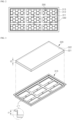
- FIG. 1 is an exploded perspective view illustrating a foam kit assembly and a battery pack including the same in accordance with an exemplary embodiment.
- FIG. 2 is a plan view illustrating a support frame and a pressing needle.
- FIG. 3 is an exploded perspective view illustrating the foam kit assembly in accordance with an exemplary embodiment.
- the battery pack including the foam kit assembly in accordance with an exemplary embodiment will be described with reference to FIGS. 1 to 3 .
- the battery pack in accordance with an exemplary embodiment may include a battery pack case 100, a plurality of battery cells 200, a foam kit assembly 300, and foam f.
- the battery pack case 100 may have an inner space to accommodate the plurality of battery cells 200 therein.
- the battery pack case 100 may have a rectangular cylinder shape. Alternatively, the battery pack case 100 may have various shapes.
- the plurality of battery cells 200, the foam kit assembly 300, and the foam f may be accommodated in the battery pack case 100.
- the plurality of battery cells 200 may be disposed below the foam kit assembly 300.
- the foam f may surround a whole of the plurality of battery cells 200 and simultaneously surround each of the plurality of battery cells 200.
- the foam f may fill a space between the plurality of battery cells 200 and an inner surface of the battery pack case 100 and simultaneously fill a gap S between the plurality of battery cells 200.
- the battery pack case 100 may include a housing 110 of which the inside is opened upward and a top cover 120 mounted to the upper opening of the housing to press the foam kit assembly 300 in a downward direction.
- the housing 110 may include a lower plate 111 having a plate shape having a predetermined area so that the plurality of battery cells 200 are seated thereon and an upper frame 112 having a rectangular cylinder shape extending along a circumference of the lower plate 111 and having a predetermined height greater than that of, e.g., the plurality of battery cells 200.
- the top cover 120 may extend in a horizontal direction and have a predetermined area to be seated on an upper end of the upper frame 112.
- the plurality of battery cells 200 may be accommodated in the inner space of the battery pack case 100 and arranged in the horizontal direction.
- Each of the plurality of battery cells 200 may be a cylindrical secondary battery cell extending in a vertical direction.
- the secondary battery cell may be formed such that an electrode assembly in which as a separation membrane is disposed between a positive electrode plate with a positive electrode tab attached and a negative electrode plate with a negative electrode tab attached, the positive electrode plate, the negative electrode plate, and the separation membrane are wound in the form of jelly roll is accommodated in the cell case.
- An electrode terminal may be formed at each of one side and the other side, which is opposite to the one side, of the secondary battery cell.
- a positive electrode terminal is formed at the one side of the secondary battery cell
- a negative electrode terminal may be formed at the other side opposite to the one side.
- the plurality of battery cells 200 may be accommodated in the inner space of the battery pack case 100.
- the plurality of battery cells 200 may be serial-connected in the row direction and parallel-connected in the column direction by a bus bar (not shown).
- the plurality of battery cells 200 may have various arrangement structures and various connection methods.
- the row direction may be a left-right direction
- the column direction may be a front and rear direction. All of the left-right direction and the front and rear direction may be referred to as a horizontal direction.
- a direction crossing the horizontal direction may be referred to as a vertical direction.
- the foam kit assembly 300 is accommodated in the inner space of the battery pack case 100 to be disposed on the plurality of battery cells 200 and isolated from the outside. Also, as the foam kit assembly 300 is pressed by a contact with the battery pack case 100, a portion of the foam kit assembly 300 may be penetrated. Here, the penetrated portion of the foam kit assembly 300 may be used as a passage through which liquid foam is discharged when the battery pack is manufactured. That is, the foam kit assembly 300 serves to supply the liquid foam to the inner space of the battery pack case 100.
- the foam kit assembly 300 may include a support frame 310, a foam kit 320, and a pressing needle 330.
- the support frame 310 may be disposed on the plurality of battery cells 200.
- the support frame 310 may extend in the horizontal direction.
- the support frame 310 may allow the foam kit 320 to be seated on a top surface thereof.
- the support frame 310 may have at least one opening so that the foam passes therethrough.
- the support frame 310 may include a bar member 311 in which the at least one opening is formed in a grid shape, an edge member 312 for supporting an edge of the frame member 311, and a hanging member 313 allowing the edge member 312 to be seated on the upper end of the upper frame 112 of the housing 110.
- the bar member 311 may have a predetermined area so that the foam kit 320 is seated thereon.
- the bar member 311 may be disposed inside the edge member 312, extend in the horizontal direction, and supported by a lower portion of the edge member 312.
- at least one opening may be formed with the grid shape in the bar member 311.
- the bar member 311 may include a plurality of first bars extending in the left-right direction and a plurality of second bars extending in the front-rear direction.
- the plurality of first bars and the plurality of second bars may be arranged in the grid shape and connected to each other.
- the edge member 312 may extend along an inner circumferential of an upper opening of the housing 110.
- the edge member 312 may have, e.g., a rectangular frame shape.
- the edge member 312 may be inserted into the upper opening of the housing 110 and contact an inner surface of the upper opening of the housing 110.
- the hanging member 313 may be formed as an upper end of the edge member 312 is bent to the outside. That is, the hanging member 313 may have a rectangular ring shape.
- the hanging member 313 may have a bottom surface seated on the upper end of the upper frame 112.
- the top cover 120 may be seated on a top surface of the hanging member 313.
- the hanging member 313 may be inserted into the upper opening of the housing 110.
- the edge member 312 may be spaced apart from the inner surface of the upper opening of the housing 110 in the upper opening of the housing 110, and the top cover 120 may be seated on the upper end of the upper frame 112 of the housing 110.
- the foam kit 320 may be seated on the support frame 310 so as to contact the top cover 120 and be pressed downward and have an accommodation space formed therein for accommodating the liquid foam. That is, the foam kit 320 temporarily stores the liquid foam therein and inj ects the liquid foam therein into the inner space of the battery pack case 100 when the battery pack is manufactured.
- the foam kit 320 may have a vertical thickness t2 greater than a vertical thickness t1 of the edge member 312. Thus, when the top cover 120 is assembled to the upper opening of the housing 110, the foam kit 320 may contact a bottom surface of the top cover 120 and be pressed downward.
- the foam kit 320 may have the vertical thickness t2 equal to the vertical thickness t1 of the edge member 312.
- the foam kit 320 may be seated on the pressing needle 330 to protrude by a predetermined height upward from the edge member 312, and the foam kit 320 may contact the bottom surface of the top cover 120 and be pressed downward when the top cover 120 is assembled to the upper opening of the housing 110.
- a protruding height of the pressing needle 330 may be determined so that the foam kit 320 protrudes by a predetermined height upward from the edge member 312 when the foam kit 320 is seated on the pressing needle 330.
- the battery pack case 100 may not include a port for injecting the liquid foam and may have a simplified structure in an exemplary embodiment. Also, by using the foam kit 320, a manufacturing process of the battery pack may be simplified because the liquid foam moves in the battery pack case 100 in an exemplary embodiment, and a battery pack manufacturing facility may be simplified because a device for forcedly injecting the liquid foam into the battery pack case 100 from the outside is not used.
- the foam kit 320 may include a pouch-type vinyl cover 321 and at least one storage chamber 322 formed in the pouch-type vinyl cover 321 to accommodate the liquid foam.
- the liquid foam may be one component type liquid foam and include various materials foamed and cured when contacting air.
- the liquid foam may maintain a liquid state as contact with air is blocked by the pouch-type vinyl cover 321 when accommodated in the storage chamber 322.
- the liquid foam may be foamed and cured as the liquid foam is leaked to the inner space of the battery pack case 100 when the pouch-type vinyl cover 321 is broken.
- predetermined heat may be generated.
- the pouch-type vinyl cover 321 may be disposed on the bar member 311.
- the pouch-type vinyl cover 321 temporarily stores the liquid foam therein and discharges the liquid foam therein to the inner space of the battery pack case 100 when a portion thereof is broken by the pressing needle 330.
- the pouch-type vinyl cover 321 may have a predetermined thickness and include a predetermined material that is melted at a temperature generated when the liquid foam is foamed and cured. Thus, when the foam f is formed as the liquid foam is completely foamed and cured, at least a portion of the pouch-type vinyl cover 321 may be melted and removed by heat.
- the pressing needle 330 protrudes from the support frame 310 to penetrate the foam kit 320. Specifically, the pressing needle 330 may protrude upward from a plurality of positions of a top surface of the bar member 331, and thus, a bottom surface of the foam kit 320 may be penetrated by the pressing needle 330 when the battery pack case 100 is assembled.
- the pressing needle 330 may have a cone shape. Alternatively, the pressing needle 330 may have various shapes.
- a gap allowing the liquid foam to flow therethrough may be formed between an outer circumferential surface of the pressing needle 330 and a penetrated portion of the foam kit 320, and the liquid foam in the foam kit 320 may flow downward through the gap.
- the plurality of battery cells 200 may be divided into a plurality of groups according to positions in the horizontal direction.
- the pressing needle 330 may be provided in plurality to be aligned to a central position of each of the plurality of groups in the vertical direction, and the plurality of pressing needles 330 may be spaced apart from each other.
- the above-described gaps allowing the liquid foam to flow therethrough may be uniformly spaced apart from each other in the horizontal direction and supply the liquid foam onto the plurality of battery cells 200 when the battery pack is manufactured.
- the foam f is discharged from the foam kit assembly 300 and filled between the inner surface of the battery pack case 100 and the foam kit assembly 300.
- the foam f may be discharged downward from the penetrated portion, which is caused by the pressing needle 330, of the foam kit 320 and fill the gap S between the plurality of battery cells 200 in the vertical direction. That is, the foam f is discharged from the penetrated portion, formed in a solid state as the liquid foam is foamed and cured, and surrounds each of the plurality of battery cells 200.
- FIG. 4 is a schematic view illustrating a foam kit in accordance with a modified example of an exemplary embodiment.
- a foam kit 320' in accordance with a modified example of an exemplary embodiment includes a pouch-type vinyl cover 321, a plurality of storage chambers 322a and 322b formed in the pouch-type vinyl cover 321 to accommodate liquid foam, and a separation membrane 323 disposed in the pouch-type vinyl cover 321 to partition the plurality of storage chambers 322a and 322b and broken by a pressure applied from a top cover 120 to the pouch-type vinyl cover 321.
- the liquid foam may be two component type liquid foam. That is, the liquid foam may include a base and a curing agent. In this case, the base and the curing agent are separated and then mixed when the foam f is formed.
- the pouch-type vinyl cover 321 may include the plurality of storage chambers 322a and 322b, the base and the curing agent of the two component type liquid foam may be respectively accommodated in the plurality of storage chambers, and then the base and the curing agent may be mixed with each other when the separation membrane 323 is broken.
- the separation membrane 323 may have a predetermined thickness to be more easily broken than the pouch-type vinyl cover 321, and the separation membrane 323 may be broken before a pressing needle 330 penetrates the pouch-type vinyl cover 321 when the pouch-type vinyl cover 321 is pressed by the top cover 120.
- the liquid foam flows downward through the gap therebetween.
- the liquid foam flows from an upper portion to a lower portion of the battery cell.
- air existing around the lower portion of the battery cell may be isolated at a lower portion of the battery pack case 100 by the liquid foam instead of being discharged to an upper side of the liquid foam.
- a predetermined gas may be discharged, and the discharged gas may be isolated at the lower portion of the battery pack case 100.
- a housing 110 of a battery pack case in accordance with another modified example of an exemplary embodiment may include a predetermined pneumatic pressure adjustment hole (not shown) so that the air and the gas smoothly moves to an upper portion of the battery pack case 100.
- the housing 110 may include a lower plate 111 having an area so that the plurality of battery cells 200 are seated thereon and an upper frame 112 extending along a circumference of the lower plate 111 and having a height greater than that of each of a plurality of battery cells 200.
- the pneumatic pressure adjustment hole may extend in the inside of the lower plate 111 and the inside of the upper frame 112 and have an inlet formed in a top surface of the lower plate 111 and an outlet formed in an inner circumferential surface or an outer circumferential surface of an upper end of the upper frame 112. At least one pneumatic pressure adjustment hole may be formed.
- the pneumatic pressure adjustment hole may prevent the air or the gas from being isolated at the lower portion of the battery pack case 100, and thus, the liquid foam may smoothly flow until the top surface of the lower plate 111.
- FIG. 5 is a view for explaining a liquid foam diffusion process and a foam formation process of a method for manufacturing a battery pack including a foam kit assembly in accordance with an exemplary embodiment.
- FIG. 6 is a view for explaining the foam formation process in accordance with an exemplary embodiment.
- the method for manufacturing the battery pack including the foam kit assembly in accordance with an exemplary embodiment may include following processes.
- a battery cell storing process performs a process of storing a plurality of battery cells 200 arranged in the horizontal direction in a housing 110 of which the inside is opened upward and each extending in the vertical direction.
- Each of the plurality of battery cells 200 may be a cylindrical secondary battery.
- the plurality of battery cells 200 may be electrically connected to each other by a bus bar (not shown).
- the plurality of battery cells 200 may be spaced a predetermined distance from each other to form a gap S therebetween.
- a foam kit assembly arrangement process performs a process of arranging a foam kit assembly 300, in which liquid foam is stored, on the plurality of battery cells 200.
- the foam kit assembly arrangement process may include: a support frame seat process of seating a support frame 310 of the foam kit assembly 300 on the plurality of battery cells 200; a foam kit seat process of seating a foam kit 320 of the foam kit assembly 300 on the support frame 310; and a pressing needle contact process of allowing the foam kit 320 and a pressing needle 330 of the foam kit assembly 300, which protrudes from the support frame 310, to contact each other.
- the foam kit 320 since the foam kit 320 is not pressed by a top cover, the foam kit 320 may be seated on the pressing needle 330.
- a battery pack case assembly process performs a process of assembling a battery pack case by mounting the top cover 120 to an upper opening of the housing 110.
- the top cover 120 may be seated and mounted onto a top surface of a hanging member 313 in a structure in which the hanging member 313 of the support frame 310 is seated on a circumference of the upper opening of the housing.
- the top cover 120 may be seated and mounted onto an upper end of the upper frame 112 of the housing 110 in a structure in which the hanging member 313 of the support frame 310 is inserted into the upper opening of the housing.
- the liquid foam diffusion process may be performed together. That is, the liquid foam diffusion process may be quickly performed by assembling the battery pack case 100 in an exemplary embodiment, and thus an entire manufacturing process of the battery pack may be reduced.
- a liquid foam diffusion process performs a process of diffusing the liquid foam to the entire inner space of the battery pack case 100 from the inside of the foam kit 320 of the foam kit assembly 300 such that the foam kit 320 of the foam kit assembly 300 contacts the bottom surface of the top cover 120 to press the foam kit 320, and a portion of the foam kit 320 of the foam kit assembly 300 is penetrated by the pressing needle 330.
- the liquid foam diffusion process may include: a foam kit pressing process of pressing the foam kit 320 downward by the top cover 120; a discharge hole forming process of forming a discharge hole by penetrating the pressing needle 330 through a bottom surface of the foam kit 320; and a liquid foam discharge process of discharging the liquid foam accommodated in the foam kit 320 onto the plurality of battery cells 200 through a gap between the discharge hole and an outer circumferential surface of the pressing needle 330.
- the pressing needle 330 may penetrate the bottom surface of the foam kit 320 by pressing the foam kit 320 by the top cover 120.
- a plurality of through-holes e.g., discharge holes, may be formed in the bottom surface of the foam kit 320, and the liquid foam that is temporarily stored in the foam kit 320 may be smoothly discharged downward through the gap between the pressing needle 330 and the through-hole.
- the liquid foam diffusion process may include: a liquid foam spreading process of spreading the liquid foam on the plurality of battery cells 200 in the horizontal direction; and a liquid foam flowing process of inducing downward flow F of the liquid foam from an upper portion to a lower portion of each of the plurality of battery cells 200. That is, the liquid foam discharged onto the plurality of battery cells 200 through the through-hole may have a predetermined viscosity.
- the liquid foam may be uniformly spread on the plurality of battery cells 200 in the horizontal direction because the liquid foam flows in the horizontal direction in which the liquid foam more easily flows before the liquid foam flows downward to the gap between the plurality of battery cells 200.
- at least one opening having a grid shape may be formed in the bar member 311.
- the liquid foam may flow downward form the upper portion to the lower portion of each of the plurality of battery cells 200 through the gap S between the plurality of battery cells 200.
- the liquid foam may be uniformly filled to the gap S between the plurality of battery cells 200 in the vertical direction.
- a foam formation process may be performed while the liquid foam spreading process and the liquid foam flowing process are performed.
- a foam formation process may perform a process of forming a solidified foam f between an inner surface of the battery pack case 100 and the foam kit assembly 300 by foaming and curing the liquid foam in the inner space of the battery pack case 100.
- the foam formation process may include: a liquid foam solidification process of solidifying the liquid foam by foaming and curing the liquid foam; and a foam kit exterior melting process of melting the pouch-type vinyl cover 321 that is an exterior of the foam kit 320 by using heat generated when the liquid foam is foamed and cured, e.g., heat of about 40°C.
- the liquid foam may be foamed and cured by contacting air in the battery pack case 100 or foamed and cured by mixing a base and curing agent.
- the foam f may be formed even in a space occupied by the pouch-type vinyl cover 321.
- only a portion of the pouch-type vinyl cover 321 is melted and removed by heat, or a whole of the pouch-type vinyl cover 321 may be remained on the support frame 310.
- the foam f formed through the foam formation process may uniformly fill the gap S between the plurality of battery cells 200 in the vertical direction, block heat transfer between the plurality of battery cells 200 after solidified, and induce a material leaked from a broken battery cell to flow away from another battery cell to prevent short-circuit between the plurality of battery cells 200.
- the foam kit assembly when the battery pack is manufactured, the foam kit assembly may be seated in the battery pack case, and then battery pack case may be assembled to simultaneously fill the foam uniformly in the battery pack case by using the foam kit assembly.
- the uniformity of the foam in the battery pack case may be secured, and the time required for manufacturing the battery pack may be reduced.
Landscapes
- Chemical & Material Sciences (AREA)
- Chemical Kinetics & Catalysis (AREA)
- Electrochemistry (AREA)
- General Chemical & Material Sciences (AREA)
- Engineering & Computer Science (AREA)
- Manufacturing & Machinery (AREA)
- Battery Mounting, Suspending (AREA)
- Secondary Cells (AREA)
- Connection Of Batteries Or Terminals (AREA)
Abstract
Description
- The present disclosure relate to a battery pack including a foam kit assembly and a manufacturing method thereof, and more particularly, to a battery pack including a foam kit assembly, which is capable of filling foam uniformly in a battery pack case, and a manufacturing method thereof.
- A secondary battery, as a rechargeable battery, is used in various fields from a smartphone to an electric vehicle. Here, the secondary battery is used in the form of one battery cell or in the form of a battery pack in which a plurality of battery cells are connected according to the kinds of devices using the secondary battery. For example, the secondary battery used in a small-sized device such as a smartphone is used in the form of one battery cell. Also, the secondary battery used in a medium and large-sized device such as an electric vehicle is used in the form of the battery pack in which the plurality of battery cells are connected.
- When the plurality of battery cells constitute the battery pack used for the medium and large-sized device, large number of battery cells is necessary to satisfy an output voltage and a charging capacity required in the medium and large-sized device. The battery cells are concentrated in a small space, and foam is filled therebetween.
- The foam performs many functions of blocking heat transfer between the plurality of battery cells, inducing a material leaked from a broken battery cell away from another battery cell, and preventing a short-circuit between the plurality of battery cells.
- The foam is injected into a battery pack housing through a plurality of ports defined in a sidewall of the battery pack housing. Since a gap between the plurality of battery cells is narrow to increase an energy density of the battery pack, filling the foam uniformly between the plurality of battery cells narrowly arranged in the battery pack housing is difficult. Also, since the foam used in the battery pack generally has a high viscosity, injecting the foam deeply into a central portion of the battery pack housing from the outside of the battery pack housing is difficult, and securing distribution uniformity of the foam in a height direction of the battery cell is difficult although the foam is deeply injected.
- The background technology of the present invention is disclosed in patent documents below.
- (Patent document 1)
KR10-2019-0097231 A - (Patent document 2)
KR10-0897899 B1 - The present disclosure provides a battery pack including a foam kit assembly capable of uniformly filling foam in a battery pack case and a manufacturing method thereof.
- In accordance with an exemplary embodiment, a battery pack includes: a battery pack case having an inner space; a plurality of battery cells accommodated in the inner space of the battery pack case, arranged in a horizontal direction, and each extending in a vertical direction; a foam kit assembly accommodated in the inner space of the battery pack case so that the foam kit assembly is disposed on the plurality of battery cells and isolated from the outside; and foam discharged from the foam kit assembly and filled between an inner surface of the battery pack case and the foam kit assembly. Here, the foam kit assembly includes: a support frame extending in the horizontal direction and having at least one opening so that liquid foam passes therethrough in the vertical direction; a foam kit seated on the support frame to contact a top cover of the battery pack case and be pressed by the top cover and having an accommodation space formed therein for accommodating the liquid foam; and a pressing needle protruding from the support frame to penetrate the foam kit. Also, the foam is formed such that the liquid foam flows downward from the accommodation space of the foam kit through a through-hole of the foam kit, which is defined by the pressing needle, to form the foam on a bottom surface of a housing of the battery pack case.
- The foam kit may have a top surface brought into contact with the top cover and pressed downward by the top cover and a bottom surface through which the pressing needle is penetrated.
- The battery pack case may include: the housing of which the inside is opened upward; and the top cover mounted to an upper opening of the housing so as to press the foam kit of the foam kit assembly downward.
- The foam may be solidified by foaming and curing of the liquid foam and uniformly fill a gap between the plurality of battery cells in the vertical direction while surrounding the plurality of battery cells.
- The support frame may support an upper shape of the foam discharged from the through-hole of the foam kit and formed between the plurality of battery cells. Here, the support frame may include: an edge member extending along an inner circumference of the upper opening of the housing; and a bar member which is disposed inside the edge member so that the foam kit is seated thereon and extends in the horizontal direction to be supported by the edge member and in which the at least one opening is formed in a grid shape.
- The pressing needle may protrude upward from a plurality of positions of a top surface of the bar member, the bottom surface of the foam kit may be penetrated by the pressing needle, and a gap through which the liquid foam flows downward may be formed between a penetrated portion of the foam kit and an outer circumferential surface of the pressing needle.
- The plurality of battery cells may be divided into a plurality of groups based on position in the horizontal direction, and the pressing needle may be provided in plurality so that a plurality of pressing needles are aligned to a central position of each of the plurality of groups in the vertical direction and spaced apart from each other in the horizontal direction.
- The foam kit may include: a pouch-type vinyl cover; and at least one storage chamber formed in the pouch-type vinyl cover to accommodate the liquid foam, and the liquid foam may be one component type liquid foam.
- The foam kit may include: a pouch-type vinyl cover; a plurality of storage chambers formed in the pouch-type vinyl cover to accommodate the liquid foam; and a separation membrane disposed in the pouch-type vinyl cover to partition the inside pouch-type vinyl cover into the plurality of storage chambers and broken by a pressure applied to the pouch-type vinyl cover from the top cover. Here, the liquid foam may be two component type liquid foam, and a base and a curing agent of the two component type liquid foam may be accommodated in the plurality of storage chambers, respectively.
- The pouch-type vinyl cover may be melted at a temperature of heat generated when the liquid foam is foamed and cured.
- In accordance with another exemplary embodiment, a method for manufacturing a battery pack includes: a battery cell storing process of storing a plurality of battery cells arranged in a horizontal direction and each extending in a vertical direction in a housing of which the inside is opened upward; a foam kit assembly arrangement process of arranging a foam kit assembly, in which liquid foam is accommodated, on the plurality of battery cells; a battery pack case assembly process of assembling a battery pack case by mounting a top cover to an upper opening of the housing; a liquid foam diffusion process of allowing a portion of the foam kit assembly to be penetrated as the foam kit assembly contacts the top cover and is pressed by the top cover and diffusing the liquid foam to an entire inner space of the battery pack case from the foam kit assembly; and a foam formation process of forming foam between an inner surface of the battery pack case and the foam kit assembly by foaming and curing the liquid foam.
- The foam kit assembly arrangement process may include: a support frame seat process of seating a support frame of the foam kit assembly on the plurality of battery cells; a foam kit seat process of seating a foam kit of the foam kit assembly on the support frame; and a pressing needle contact process of allowing the foam kit and a pressing needle of the foam kit assembly, which protrudes from the support frame, to contact each other.
- The liquid foam diffusion process may include: a foam kit pressing process of pressing the foam kit downward by the top cover; a discharge hole forming process of forming a discharge hole by penetrating the pressing needle through a bottom surface of the foam kit; and a liquid foam discharge process of discharging the liquid foam accommodated in the foam kit onto the plurality of battery cells through a gap between the discharge hole and an outer circumferential surface of the pressing needle.
- The liquid foam diffusion process may include: a liquid foam spreading process of spreading the liquid foam on the plurality of battery cells in the horizontal direction; and a liquid foam flowing process of inducing a downward flow of the liquid foam from an upper portion to a lower portion of each of the plurality of battery cells.
- The foam formation process may include: a liquid foam solidification process of solidifying the liquid foam by foaming and curing the liquid foam; and a foam kit exterior melting process of melting a pouch-type vinyl cover that is an exterior of the foam kit by using heat generated when the liquid foam is foamed and cured.
- The battery cell may be a cylindrical secondary battery, and foam formed through the foam formation process uniformly may fill a gap between the plurality of battery cells in the vertical direction.
-
-
FIG. 1 is an exploded perspective view illustrating a foam kit assembly and a battery pack including the same in accordance with an exemplary embodiment. -
FIG. 2 is a plan view illustrating a support frame and a pressing needle in accordance with an exemplary embodiment. -
FIG. 3 is an exploded perspective view illustrating the foam kit assembly in accordance with an exemplary embodiment. -
FIG. 4 is a schematic view illustrating a foam kit in accordance with a modified example of an exemplary embodiment. -
FIG. 5 is a view for explaining a liquid foam diffusion process and a foam formation process of a method for manufacturing a battery pack including a foam kit assembly in accordance with an exemplary embodiment. -
FIG. 6 is a view for explaining the foam formation process in accordance with an exemplary embodiment. - Hereinafter, embodiments of the present invention will be described in detail with reference to the accompanying drawings. The present invention may, however, be embodied in different forms and should not be construed as limited to the embodiments set forth herein. Rather, these embodiments are provided so that this disclosure will be thorough and complete, and will fully convey the scope of the present invention to those skilled in the art. In the figures, the dimensions of layers and regions are exaggerated for clarity of illustration. Like reference numerals refer to like elements throughout.
- Hereinafter, embodiments of the inventive concept will be described with reference to the accompanying drawings.
-
FIG. 1 is an exploded perspective view illustrating a foam kit assembly and a battery pack including the same in accordance with an exemplary embodiment.FIG. 2 is a plan view illustrating a support frame and a pressing needle.FIG. 3 is an exploded perspective view illustrating the foam kit assembly in accordance with an exemplary embodiment. - The battery pack including the foam kit assembly in accordance with an exemplary embodiment will be described with reference to
FIGS. 1 to 3 . - The battery pack in accordance with an exemplary embodiment may include a battery pack case 100, a plurality of
battery cells 200, a foam kit assembly 300, and foam f. - The battery pack case 100 may have an inner space to accommodate the plurality of
battery cells 200 therein. The battery pack case 100 may have a rectangular cylinder shape. Alternatively, the battery pack case 100 may have various shapes. The plurality ofbattery cells 200, the foam kit assembly 300, and the foam f may be accommodated in the battery pack case 100. Here, the plurality ofbattery cells 200 may be disposed below the foam kit assembly 300. Also, the foam f may surround a whole of the plurality ofbattery cells 200 and simultaneously surround each of the plurality ofbattery cells 200. Specifically, the foam f may fill a space between the plurality ofbattery cells 200 and an inner surface of the battery pack case 100 and simultaneously fill a gap S between the plurality ofbattery cells 200. - The battery pack case 100 may include a
housing 110 of which the inside is opened upward and atop cover 120 mounted to the upper opening of the housing to press the foam kit assembly 300 in a downward direction. - The
housing 110 may include alower plate 111 having a plate shape having a predetermined area so that the plurality ofbattery cells 200 are seated thereon and anupper frame 112 having a rectangular cylinder shape extending along a circumference of thelower plate 111 and having a predetermined height greater than that of, e.g., the plurality ofbattery cells 200. - The
top cover 120 may extend in a horizontal direction and have a predetermined area to be seated on an upper end of theupper frame 112. - The plurality of
battery cells 200 may be accommodated in the inner space of the battery pack case 100 and arranged in the horizontal direction. Each of the plurality ofbattery cells 200 may be a cylindrical secondary battery cell extending in a vertical direction. - The secondary battery cell may be formed such that an electrode assembly in which as a separation membrane is disposed between a positive electrode plate with a positive electrode tab attached and a negative electrode plate with a negative electrode tab attached, the positive electrode plate, the negative electrode plate, and the separation membrane are wound in the form of jelly roll is accommodated in the cell case. An electrode terminal may be formed at each of one side and the other side, which is opposite to the one side, of the secondary battery cell. Here, when a positive electrode terminal is formed at the one side of the secondary battery cell, a negative electrode terminal may be formed at the other side opposite to the one side.
- For example, as the plurality of
battery cells 200 are arranged in a row direction and a column direction such that battery cells arranged in the row direction are arranged so that a positive electrode terminal and a negative electrode terminal are alternately arranged upward, and battery cells arranged in the column direction are arranged so that the same electrode terminal are arranged upward, the plurality ofbattery cells 200 may be accommodated in the inner space of the battery pack case 100. Also, the plurality ofbattery cells 200 may be serial-connected in the row direction and parallel-connected in the column direction by a bus bar (not shown). However, the plurality ofbattery cells 200 may have various arrangement structures and various connection methods. Here, the row direction may be a left-right direction, and the column direction may be a front and rear direction. All of the left-right direction and the front and rear direction may be referred to as a horizontal direction. Also, a direction crossing the horizontal direction may be referred to as a vertical direction. - The foam kit assembly 300 is accommodated in the inner space of the battery pack case 100 to be disposed on the plurality of
battery cells 200 and isolated from the outside. Also, as the foam kit assembly 300 is pressed by a contact with the battery pack case 100, a portion of the foam kit assembly 300 may be penetrated. Here, the penetrated portion of the foam kit assembly 300 may be used as a passage through which liquid foam is discharged when the battery pack is manufactured. That is, the foam kit assembly 300 serves to supply the liquid foam to the inner space of the battery pack case 100. - The foam kit assembly 300 may include a
support frame 310, afoam kit 320, and apressing needle 330. - The
support frame 310 may be disposed on the plurality ofbattery cells 200. Thesupport frame 310 may extend in the horizontal direction. Thesupport frame 310 may allow thefoam kit 320 to be seated on a top surface thereof. Thesupport frame 310 may have at least one opening so that the foam passes therethrough. - The
support frame 310 may include abar member 311 in which the at least one opening is formed in a grid shape, anedge member 312 for supporting an edge of theframe member 311, and a hangingmember 313 allowing theedge member 312 to be seated on the upper end of theupper frame 112 of thehousing 110. - The
bar member 311 may have a predetermined area so that thefoam kit 320 is seated thereon. Thebar member 311 may be disposed inside theedge member 312, extend in the horizontal direction, and supported by a lower portion of theedge member 312. Also, at least one opening may be formed with the grid shape in thebar member 311. For example, thebar member 311 may include a plurality of first bars extending in the left-right direction and a plurality of second bars extending in the front-rear direction. Here, the plurality of first bars and the plurality of second bars may be arranged in the grid shape and connected to each other. - The
edge member 312 may extend along an inner circumferential of an upper opening of thehousing 110. Theedge member 312 may have, e.g., a rectangular frame shape. Theedge member 312 may be inserted into the upper opening of thehousing 110 and contact an inner surface of the upper opening of thehousing 110. - The hanging
member 313 may be formed as an upper end of theedge member 312 is bent to the outside. That is, the hangingmember 313 may have a rectangular ring shape. The hangingmember 313 may have a bottom surface seated on the upper end of theupper frame 112. Thetop cover 120 may be seated on a top surface of the hangingmember 313. - Alternatively, the hanging
member 313 may be inserted into the upper opening of thehousing 110. In this case, theedge member 312 may be spaced apart from the inner surface of the upper opening of thehousing 110 in the upper opening of thehousing 110, and thetop cover 120 may be seated on the upper end of theupper frame 112 of thehousing 110. - The
foam kit 320 may be seated on thesupport frame 310 so as to contact thetop cover 120 and be pressed downward and have an accommodation space formed therein for accommodating the liquid foam. That is, thefoam kit 320 temporarily stores the liquid foam therein and inj ects the liquid foam therein into the inner space of the battery pack case 100 when the battery pack is manufactured. - The
foam kit 320 may have a vertical thickness t2 greater than a vertical thickness t1 of theedge member 312. Thus, when thetop cover 120 is assembled to the upper opening of thehousing 110, thefoam kit 320 may contact a bottom surface of thetop cover 120 and be pressed downward. - Alternatively, the
foam kit 320 may have the vertical thickness t2 equal to the vertical thickness t1 of theedge member 312. In this case, thefoam kit 320 may be seated on thepressing needle 330 to protrude by a predetermined height upward from theedge member 312, and thefoam kit 320 may contact the bottom surface of thetop cover 120 and be pressed downward when thetop cover 120 is assembled to the upper opening of thehousing 110. - When the vertical thickness t2 of the
foam kit 320 is less than the vertical thickness t1 of theedge member 312, a protruding height of thepressing needle 330 may be determined so that thefoam kit 320 protrudes by a predetermined height upward from theedge member 312 when thefoam kit 320 is seated on thepressing needle 330. - By using the
foam kit 320, the battery pack case 100 may not include a port for injecting the liquid foam and may have a simplified structure in an exemplary embodiment. Also, by using thefoam kit 320, a manufacturing process of the battery pack may be simplified because the liquid foam moves in the battery pack case 100 in an exemplary embodiment, and a battery pack manufacturing facility may be simplified because a device for forcedly injecting the liquid foam into the battery pack case 100 from the outside is not used. - The
foam kit 320 may include a pouch-type vinyl cover 321 and at least onestorage chamber 322 formed in the pouch-type vinyl cover 321 to accommodate the liquid foam. - The liquid foam may be one component type liquid foam and include various materials foamed and cured when contacting air. The liquid foam may maintain a liquid state as contact with air is blocked by the pouch-
type vinyl cover 321 when accommodated in thestorage chamber 322. The liquid foam may be foamed and cured as the liquid foam is leaked to the inner space of the battery pack case 100 when the pouch-type vinyl cover 321 is broken. Here, predetermined heat may be generated. - The pouch-
type vinyl cover 321 may be disposed on thebar member 311. The pouch-type vinyl cover 321 temporarily stores the liquid foam therein and discharges the liquid foam therein to the inner space of the battery pack case 100 when a portion thereof is broken by thepressing needle 330. The pouch-type vinyl cover 321 may have a predetermined thickness and include a predetermined material that is melted at a temperature generated when the liquid foam is foamed and cured. Thus, when the foam f is formed as the liquid foam is completely foamed and cured, at least a portion of the pouch-type vinyl cover 321 may be melted and removed by heat. - The
pressing needle 330 protrudes from thesupport frame 310 to penetrate thefoam kit 320. Specifically, thepressing needle 330 may protrude upward from a plurality of positions of a top surface of the bar member 331, and thus, a bottom surface of thefoam kit 320 may be penetrated by thepressing needle 330 when the battery pack case 100 is assembled. Thepressing needle 330 may have a cone shape. Alternatively, thepressing needle 330 may have various shapes. - Here, a gap allowing the liquid foam to flow therethrough may be formed between an outer circumferential surface of the
pressing needle 330 and a penetrated portion of thefoam kit 320, and the liquid foam in thefoam kit 320 may flow downward through the gap. - The plurality of
battery cells 200 may be divided into a plurality of groups according to positions in the horizontal direction. Also, thepressing needle 330 may be provided in plurality to be aligned to a central position of each of the plurality of groups in the vertical direction, and the plurality of pressingneedles 330 may be spaced apart from each other. Thus, the above-described gaps allowing the liquid foam to flow therethrough may be uniformly spaced apart from each other in the horizontal direction and supply the liquid foam onto the plurality ofbattery cells 200 when the battery pack is manufactured. - The foam f is discharged from the foam kit assembly 300 and filled between the inner surface of the battery pack case 100 and the foam kit assembly 300. Here, the foam f may be discharged downward from the penetrated portion, which is caused by the
pressing needle 330, of thefoam kit 320 and fill the gap S between the plurality ofbattery cells 200 in the vertical direction. That is, the foam f is discharged from the penetrated portion, formed in a solid state as the liquid foam is foamed and cured, and surrounds each of the plurality ofbattery cells 200. -
FIG. 4 is a schematic view illustrating a foam kit in accordance with a modified example of an exemplary embodiment. - Referring to
FIG. 4 , a foam kit 320' in accordance with a modified example of an exemplary embodiment includes a pouch-type vinyl cover 321, a plurality ofstorage chambers type vinyl cover 321 to accommodate liquid foam, and aseparation membrane 323 disposed in the pouch-type vinyl cover 321 to partition the plurality ofstorage chambers top cover 120 to the pouch-type vinyl cover 321. - Here, the liquid foam may be two component type liquid foam. That is, the liquid foam may include a base and a curing agent. In this case, the base and the curing agent are separated and then mixed when the foam f is formed. Thus, the pouch-
type vinyl cover 321 may include the plurality ofstorage chambers separation membrane 323 is broken. Also, theseparation membrane 323 may have a predetermined thickness to be more easily broken than the pouch-type vinyl cover 321, and theseparation membrane 323 may be broken before apressing needle 330 penetrates the pouch-type vinyl cover 321 when the pouch-type vinyl cover 321 is pressed by thetop cover 120. - As the
foam kit 320 is penetrated by thepressing needle 330, the liquid foam flows downward through the gap therebetween. Here, the liquid foam flows from an upper portion to a lower portion of the battery cell. Here, air existing around the lower portion of the battery cell may be isolated at a lower portion of the battery pack case 100 by the liquid foam instead of being discharged to an upper side of the liquid foam. Also, when the liquid foam is solidified while being foamed and cured, a predetermined gas may be discharged, and the discharged gas may be isolated at the lower portion of the battery pack case 100. - A
housing 110 of a battery pack case in accordance with another modified example of an exemplary embodiment may include a predetermined pneumatic pressure adjustment hole (not shown) so that the air and the gas smoothly moves to an upper portion of the battery pack case 100. - Specifically, the
housing 110 may include alower plate 111 having an area so that the plurality ofbattery cells 200 are seated thereon and anupper frame 112 extending along a circumference of thelower plate 111 and having a height greater than that of each of a plurality ofbattery cells 200. Here, the pneumatic pressure adjustment hole may extend in the inside of thelower plate 111 and the inside of theupper frame 112 and have an inlet formed in a top surface of thelower plate 111 and an outlet formed in an inner circumferential surface or an outer circumferential surface of an upper end of theupper frame 112. At least one pneumatic pressure adjustment hole may be formed. - The pneumatic pressure adjustment hole may prevent the air or the gas from being isolated at the lower portion of the battery pack case 100, and thus, the liquid foam may smoothly flow until the top surface of the
lower plate 111. -
FIG. 5 is a view for explaining a liquid foam diffusion process and a foam formation process of a method for manufacturing a battery pack including a foam kit assembly in accordance with an exemplary embodiment.FIG. 6 is a view for explaining the foam formation process in accordance with an exemplary embodiment. - The method for manufacturing the battery pack including the foam kit assembly in accordance with an exemplary embodiment will be described with reference to
FIGS. 1 to 6 . Here, when the method for manufacturing the battery pack including the foam kit assembly is described, features overlapped with the above description of the battery pack including the foam kit assembly in accordance with an exemplary embodiment will be omitted or simply described. - The method for manufacturing the battery pack including the foam kit assembly in accordance with an exemplary embodiment may include following processes.
- A battery cell storing process performs a process of storing a plurality of
battery cells 200 arranged in the horizontal direction in ahousing 110 of which the inside is opened upward and each extending in the vertical direction. Each of the plurality ofbattery cells 200 may be a cylindrical secondary battery. The plurality ofbattery cells 200 may be electrically connected to each other by a bus bar (not shown). The plurality ofbattery cells 200 may be spaced a predetermined distance from each other to form a gap S therebetween. - A foam kit assembly arrangement process performs a process of arranging a foam kit assembly 300, in which liquid foam is stored, on the plurality of
battery cells 200. - The foam kit assembly arrangement process may include: a support frame seat process of seating a
support frame 310 of the foam kit assembly 300 on the plurality ofbattery cells 200; a foam kit seat process of seating afoam kit 320 of the foam kit assembly 300 on thesupport frame 310; and a pressing needle contact process of allowing thefoam kit 320 and apressing needle 330 of the foam kit assembly 300, which protrudes from thesupport frame 310, to contact each other. In this process, since thefoam kit 320 is not pressed by a top cover, thefoam kit 320 may be seated on thepressing needle 330. - A battery pack case assembly process performs a process of assembling a battery pack case by mounting the
top cover 120 to an upper opening of thehousing 110. - For example, the
top cover 120 may be seated and mounted onto a top surface of a hangingmember 313 in a structure in which the hangingmember 313 of thesupport frame 310 is seated on a circumference of the upper opening of the housing. Thetop cover 120 may be seated and mounted onto an upper end of theupper frame 112 of thehousing 110 in a structure in which the hangingmember 313 of thesupport frame 310 is inserted into the upper opening of the housing. While the battery pack case assembly process is performed, the liquid foam diffusion process may be performed together. That is, the liquid foam diffusion process may be quickly performed by assembling the battery pack case 100 in an exemplary embodiment, and thus an entire manufacturing process of the battery pack may be reduced. - A liquid foam diffusion process performs a process of diffusing the liquid foam to the entire inner space of the battery pack case 100 from the inside of the
foam kit 320 of the foam kit assembly 300 such that thefoam kit 320 of the foam kit assembly 300 contacts the bottom surface of thetop cover 120 to press thefoam kit 320, and a portion of thefoam kit 320 of the foam kit assembly 300 is penetrated by thepressing needle 330. - The liquid foam diffusion process may include: a foam kit pressing process of pressing the
foam kit 320 downward by thetop cover 120; a discharge hole forming process of forming a discharge hole by penetrating thepressing needle 330 through a bottom surface of thefoam kit 320; and a liquid foam discharge process of discharging the liquid foam accommodated in thefoam kit 320 onto the plurality ofbattery cells 200 through a gap between the discharge hole and an outer circumferential surface of thepressing needle 330. - That is, while assembling the battery pack case 100 by mounting the
top cover 120 to thehousing 110, thepressing needle 330 may penetrate the bottom surface of thefoam kit 320 by pressing thefoam kit 320 by thetop cover 120. Thus, a plurality of through-holes, e.g., discharge holes, may be formed in the bottom surface of thefoam kit 320, and the liquid foam that is temporarily stored in thefoam kit 320 may be smoothly discharged downward through the gap between thepressing needle 330 and the through-hole. - Alternatively, the liquid foam diffusion process may include: a liquid foam spreading process of spreading the liquid foam on the plurality of
battery cells 200 in the horizontal direction; and a liquid foam flowing process of inducing downward flow F of the liquid foam from an upper portion to a lower portion of each of the plurality ofbattery cells 200. That is, the liquid foam discharged onto the plurality ofbattery cells 200 through the through-hole may have a predetermined viscosity. The liquid foam may be uniformly spread on the plurality ofbattery cells 200 in the horizontal direction because the liquid foam flows in the horizontal direction in which the liquid foam more easily flows before the liquid foam flows downward to the gap between the plurality ofbattery cells 200. Here, at least one opening having a grid shape may be formed in thebar member 311. Thereafter, the liquid foam may flow downward form the upper portion to the lower portion of each of the plurality ofbattery cells 200 through the gap S between the plurality ofbattery cells 200. Here, the liquid foam may be uniformly filled to the gap S between the plurality ofbattery cells 200 in the vertical direction. A foam formation process may be performed while the liquid foam spreading process and the liquid foam flowing process are performed. - A foam formation process may perform a process of forming a solidified foam f between an inner surface of the battery pack case 100 and the foam kit assembly 300 by foaming and curing the liquid foam in the inner space of the battery pack case 100.
- That is, the foam formation process may include: a liquid foam solidification process of solidifying the liquid foam by foaming and curing the liquid foam; and a foam kit exterior melting process of melting the pouch-
type vinyl cover 321 that is an exterior of thefoam kit 320 by using heat generated when the liquid foam is foamed and cured, e.g., heat of about 40°C. The liquid foam may be foamed and cured by contacting air in the battery pack case 100 or foamed and cured by mixing a base and curing agent. When the pouch-type vinyl cover 321 of thefoam kit 320 is melted by heat, the foam f may be formed even in a space occupied by the pouch-type vinyl cover 321. Alternatively, only a portion of the pouch-type vinyl cover 321 is melted and removed by heat, or a whole of the pouch-type vinyl cover 321 may be remained on thesupport frame 310. - The foam f formed through the foam formation process may uniformly fill the gap S between the plurality of
battery cells 200 in the vertical direction, block heat transfer between the plurality ofbattery cells 200 after solidified, and induce a material leaked from a broken battery cell to flow away from another battery cell to prevent short-circuit between the plurality ofbattery cells 200. - In accordance with the exemplary embodiment, when the battery pack is manufactured, the foam kit assembly may be seated in the battery pack case, and then battery pack case may be assembled to simultaneously fill the foam uniformly in the battery pack case by using the foam kit assembly. Thus, the uniformity of the foam in the battery pack case may be secured, and the time required for manufacturing the battery pack may be reduced.
- Although the embodiments of the present invention have been described, it is understood that the present invention should not be limited to these embodiments but various changes and modifications can be made by one ordinary skilled in the art within the spirit and scope of the present invention as hereinafter claimed. Therefore, it will be readily understood by those skilled in the art that various modifications and changes can be made thereto without departing from the spirit and scope of the present invention defined by the appended claims.
Claims (17)
- A battery pack comprising:a battery pack case having an inner space;a plurality of battery cells accommodated in the inner space of the battery pack case, arranged in a horizontal direction, and each extending in a vertical direction;a foam kit assembly accommodated in the inner space of the battery pack case so that the foam kit assembly is disposed on the plurality of battery cells and isolated from the outside; andfoam discharged from the foam kit assembly and filled between an inner surface of the battery pack case and the foam kit assembly,wherein the foam kit assembly comprises:a support frame extending in the horizontal direction and having at least one opening so that liquid foam passes therethrough in the vertical direction;a foam kit seated on the support frame to contact a top cover of the battery pack case and be pressed by the top cover and having an accommodation space formed therein for accommodating the liquid foam; anda pressing needle protruding from the support frame to penetrate the foam kit,wherein the foam is formed such that the liquid foam flows downward from the accommodation space of the foam kit through a through-hole of the foam kit, which is defined by the pressing needle, to form the foam on a bottom surface of a housing of the battery pack case.
- The battery pack of claim 1, wherein the foam kit has a top surface brought into contact with the top cover and pressed downward by the top cover and a bottom surface through which the pressing needle is penetrated.
- The battery pack of claim 2, wherein the battery pack case comprises:the housing of which the inside is opened upward; andthe top cover mounted to an upper opening of the housing so as to press the foam kit of the foam kit assembly downward.
- The battery pack of claim 3, wherein the foam is solidified by foaming and curing of the liquid foam and uniformly fills a gap between the plurality of battery cells in the vertical direction while surrounding the plurality of battery cells.
- The battery pack of claim 4, wherein the support frame supports an upper shape of the foam discharged from the through-hole of the foam kit and formed between the plurality of battery cells,
wherein the support frame comprises:an edge member extending along an inner circumference of the upper opening of the housing; anda bar member which is disposed inside the edge member so that the foam kit is seated thereon and extends in the horizontal direction to be supported by the edge member and in which the at least one opening is formed in a grid shape. - The battery pack of claim 5, wherein the pressing needle protrudes upward from a plurality of positions of a top surface of the bar member,the bottom surface of the foam kit is penetrated by the pressing needle, anda gap through which the liquid foam flows downward is formed between a penetrated portion of the foam kit and an outer circumferential surface of the pressing needle.
- The battery pack of claim 4, wherein the plurality of battery cells are divided into a plurality of groups based on position in the horizontal direction, and
the pressing needle is provided in plurality so that a plurality of pressing needles are aligned to a central position of each of the plurality of groups in the vertical direction and spaced apart from each other in the horizontal direction. - The battery pack of claim 4, wherein the foam kit comprises:a pouch-type vinyl cover; andat least one storage chamber formed in the pouch-type vinyl cover to accommodate the liquid foam,wherein the liquid foam is one component type liquid foam.
- The battery pack of claim 4, wherein the foam kit comprises:a pouch-type vinyl cover;a plurality of storage chambers formed in the pouch-type vinyl cover to accommodate the liquid foam; anda separation membrane disposed in the pouch-type vinyl cover to partition the inside pouch-type vinyl cover into the plurality of storage chambers and broken by a pressure applied to the pouch-type vinyl cover from the top cover,wherein the liquid foam is two component type liquid foam, anda base and a curing agent of the two component type liquid foam are accommodated in the plurality of storage chambers, respectively.
- The battery pack of claim 8 or 9, wherein the pouch-type vinyl cover is melted at a temperature of heat generated when the liquid foam is foamed and cured.
- The battery pack of claim 3, wherein the housing comprises:a lower plate having an area on which the plurality of battery cells are seated; andan upper frame extending along a circumference of the lower plate and having a height greater than that of each of the plurality of battery cells,wherein the battery pack further comprise at least one pneumatic pressure adjustment hole extending in the inside of the lower plate and the inside of the upper frame and having an inlet formed in a top surface of the lower plate and an outlet formed in an inner circumferential surface or an outer circumferential surface of an upper end of the upper frame.
- A method for manufacturing a battery pack, comprising:a battery cell storing process of storing a plurality of battery cells arranged in a horizontal direction and each extending in a vertical direction in a housing of which the inside is opened upward;a foam kit assembly arrangement process of arranging a foam kit assembly, in which liquid foam is accommodated, on the plurality of battery cells;a battery pack case assembly process of assembling a battery pack case by mounting a top cover to an upper opening of the housing;a liquid foam diffusion process of allowing a portion of the foam kit assembly to be penetrated as the foam kit assembly contacts the top cover and is pressed by the top cover and diffusing the liquid foam to an entire inner space of the battery pack case from the foam kit assembly; anda foam formation process of forming foam between an inner surface of the battery pack case and the foam kit assembly by foaming and curing the liquid foam.
- The method of claim 12, wherein the foam kit assembly arrangement process comprises:a support frame seat process of seating a support frame of the foam kit assembly on the plurality of battery cells;a foam kit seat process of seating a foam kit of the foam kit assembly on the support frame; anda pressing needle contact process of allowing the foam kit and a pressing needle of the foam kit assembly, which protrudes from the support frame, to contact each other.
- The method of claim 13, wherein the liquid foam diffusion process comprises:a foam kit pressing process of pressing the foam kit downward by the top cover;a discharge hole forming process of forming a discharge hole by penetrating the pressing needle through a bottom surface of the foam kit; anda liquid foam discharge process of discharging the liquid foam accommodated in the foam kit onto the plurality of battery cells through a gap between the discharge hole and an outer circumferential surface of the pressing needle.
- The method of claim 14, wherein the liquid foam diffusion process comprises:a liquid foam spreading process of spreading the liquid foam on the plurality of battery cells in the horizontal direction; anda liquid foam flowing process of inducing a downward flow of the liquid foam from an upper portion to a lower portion of each of the plurality of battery cells.
- The method of claim 14, wherein the foam formation process comprises:a liquid foam solidification process of solidifying the liquid foam by foaming and curing the liquid foam; anda foam kit exterior melting process of melting a pouch-type vinyl cover that is an exterior of the foam kit by using heat generated when the liquid foam is foamed and cured.
- The method of claim 15, wherein the battery cell is a cylindrical secondary battery, and
foam formed through the foam formation process uniformly fills a gap between the plurality of battery cells in the vertical direction.
Applications Claiming Priority (2)
| Application Number | Priority Date | Filing Date | Title |
|---|---|---|---|
| KR1020200133011A KR102737970B1 (en) | 2020-10-14 | 2020-10-14 | Battery pack having foam kit assembly and manufacturing method thereof |
| PCT/KR2021/014080 WO2022080845A1 (en) | 2020-10-14 | 2021-10-13 | Battery pack including foam kit assembly, and manufacturing method therefor |
Publications (2)
| Publication Number | Publication Date |
|---|---|
| EP4213287A1 true EP4213287A1 (en) | 2023-07-19 |
| EP4213287A4 EP4213287A4 (en) | 2024-03-20 |
Family
ID=81207350
Family Applications (1)
| Application Number | Title | Priority Date | Filing Date |
|---|---|---|---|
| EP21880492.0A Pending EP4213287A4 (en) | 2020-10-14 | 2021-10-13 | BATTERY PACK COMPRISING A FOAM KIT ASSEMBLY AND METHOD FOR MANUFACTURING SAME |
Country Status (6)
| Country | Link |
|---|---|
| US (1) | US12614798B2 (en) |
| EP (1) | EP4213287A4 (en) |
| JP (1) | JP7657914B2 (en) |
| KR (1) | KR102737970B1 (en) |
| CN (1) | CN116368668B (en) |
| WO (1) | WO2022080845A1 (en) |
Families Citing this family (5)
| Publication number | Priority date | Publication date | Assignee | Title |
|---|---|---|---|---|
| US11710957B1 (en) * | 2022-10-07 | 2023-07-25 | Archer Aviation, Inc. | Systems and methods for redundant control of active fuses for battery pack safety |
| US12555994B2 (en) | 2022-10-07 | 2026-02-17 | Archer Aviation Inc. | Systems and methods for improved battery assemblies for eVTOL aircraft |
| WO2024107608A1 (en) * | 2022-11-14 | 2024-05-23 | Archer Aviation Inc. | Systems and methods for improved battery assemblies for evtol aircraft |
| EP4576360A1 (en) * | 2023-12-20 | 2025-06-25 | Rimac Technology LLC | Battery venting system |
| EP4704222A1 (en) * | 2024-08-28 | 2026-03-04 | Rimac Technology LLC | Energy storage system, and method for manufacturing an energy storage system |
Family Cites Families (21)
| Publication number | Priority date | Publication date | Assignee | Title |
|---|---|---|---|---|
| US3269865A (en) | 1963-05-20 | 1966-08-30 | Ford Motor Co | Battery elements anchored with urethane foam |
| US3919371A (en) | 1969-07-17 | 1975-11-11 | Otto Jache | Leakproof bonding of storage battery components |
| JPS59128774A (en) | 1983-01-14 | 1984-07-24 | Fuji Elelctrochem Co Ltd | Manufacture of battery |
| JP2902280B2 (en) | 1993-11-24 | 1999-06-07 | 三菱重工業株式会社 | Manufacturing method of sealed secondary battery |
| JP2000243364A (en) * | 1999-02-24 | 2000-09-08 | Matsushita Electric Ind Co Ltd | Battery pack |
| DE102007010739B4 (en) | 2007-02-27 | 2009-01-29 | Daimler Ag | Battery with a heat conducting plate |
| KR100897899B1 (en) | 2008-06-04 | 2009-05-18 | (주)화인 | Foam molding method of liquid silicone rubber |
| FR2962261B1 (en) * | 2010-07-02 | 2013-08-02 | Saft Groupe Sa | BATTERY OF ELECTROCHEMICAL GENERATORS COMPRISING FOAM AS FILLING MATERIAL BETWEEN GENERATORS |
| DE102011075318A1 (en) | 2011-05-05 | 2012-11-08 | Sb Limotive Company Ltd. | Battery housing for lithium-ion cells |
| JP5760713B2 (en) * | 2011-06-03 | 2015-08-12 | トヨタ自動車株式会社 | Battery pack |
| CN104303334B (en) | 2013-05-15 | 2018-03-20 | 三洋电机株式会社 | Battery pack and battery pack manufacturing method |
| US10347894B2 (en) | 2017-01-20 | 2019-07-09 | Tesla, Inc. | Energy storage system |
| US20150364730A1 (en) * | 2014-06-11 | 2015-12-17 | Nitto Denko Automotive, Inc. | Battery shield wrap |
| KR102394963B1 (en) | 2017-02-08 | 2022-05-04 | 엘켐 실리콘즈 유에스에이 코포레이션 | Secondary battery pack with improved thermal management |
| KR102275878B1 (en) * | 2017-04-04 | 2021-07-08 | 주식회사 엘지에너지솔루션 | Method for producing cell module improved in characteristics of safety |
| KR101984817B1 (en) | 2017-05-11 | 2019-05-31 | 주식회사 대경산전 | Automatic fire extinguishing systems for energy storage systems |
| KR102388127B1 (en) | 2018-01-31 | 2022-04-19 | 주식회사 엘지에너지솔루션 | Top cover, battery module using the same, and battery pack and vehicle including the same |
| CN108539065B (en) * | 2018-03-12 | 2020-09-18 | 浙江零跑科技有限公司 | Battery pressure plate and battery ventilation and cooling system with the battery pressure plate |
| JP7544685B2 (en) | 2018-07-30 | 2024-09-03 | カデンツァ・イノベーション・インコーポレイテッド | Housing for a rechargeable battery |
| KR102753461B1 (en) | 2018-12-26 | 2025-01-09 | 주식회사 엘지에너지솔루션 | A battery module with efficient assembly structure, a battery pack and a vehicle comprising the same |
| DE102019203043A1 (en) * | 2019-03-06 | 2020-09-10 | Ford Global Technologies, Llc | Securing a vehicle battery with foam |
-
2020
- 2020-10-14 KR KR1020200133011A patent/KR102737970B1/en active Active
-
2021
- 2021-10-13 EP EP21880492.0A patent/EP4213287A4/en active Pending
- 2021-10-13 CN CN202180065718.7A patent/CN116368668B/en active Active
- 2021-10-13 US US18/030,161 patent/US12614798B2/en active Active
- 2021-10-13 JP JP2023514128A patent/JP7657914B2/en active Active
- 2021-10-13 WO PCT/KR2021/014080 patent/WO2022080845A1/en not_active Ceased
Also Published As
| Publication number | Publication date |
|---|---|
| CN116368668A (en) | 2023-06-30 |
| EP4213287A4 (en) | 2024-03-20 |
| CN116368668B (en) | 2026-02-24 |
| JP7657914B2 (en) | 2025-04-07 |
| US20230378582A1 (en) | 2023-11-23 |
| JP2023540722A (en) | 2023-09-26 |
| KR20220049410A (en) | 2022-04-21 |
| KR102737970B1 (en) | 2024-12-04 |
| US12614798B2 (en) | 2026-04-28 |
| WO2022080845A1 (en) | 2022-04-21 |
Similar Documents
| Publication | Publication Date | Title |
|---|---|---|
| US12614798B2 (en) | Battery pack including foam kit assembly, and manufacturing method therefor | |
| US20230238631A1 (en) | Battery pack | |
| KR102640329B1 (en) | Battery module | |
| US11769921B2 (en) | Battery pack | |
| US8852779B2 (en) | Battery pack | |
| KR20200080067A (en) | Battery module, battery pack comprising the battery module and vehicle comprising the battery pack | |
| KR20210061829A (en) | Battery module, battery pack and vehicle comprising the battery module | |
| US12506200B2 (en) | Method of manufacturing battery module capable of preventing chain ignition | |
| CN217719780U (en) | Battery structure, battery package and consumer | |
| EP1198853A1 (en) | Electrolyte baffling plug and battery cover | |
| JP2023540722A5 (en) | ||
| KR20210090938A (en) | Battery pack | |
| US3795543A (en) | Bi-polar lead-acid storage battery | |
| JP2021131967A (en) | Battery pack and manufacturing method of the battery pack | |
| CN105765754A (en) | Stirring elements, integrated series of stirring elements and accumulators | |
| CN119812599A (en) | Front terminal vertical wide tab direct-connected bipolar lead-acid battery and assembly method thereof | |
| EP4131603B1 (en) | Battery pack and manufacturing method therefor | |
| JP2022552858A (en) | Cylindrical rechargeable battery with flexible input | |
| KR20220053269A (en) | Battery pack and manufacturing method thereof | |
| KR20240098987A (en) | Battery pack and vehicle comprising the battery pack | |
| US3808055A (en) | Battery, components and methods of making and activating | |
| KR20230055046A (en) | Battery module for preventing the spread of fire and method thereof | |
| KR102872914B1 (en) | Battery assembly, battery pack and vehicle comprising the same | |
| EP4475314A1 (en) | Battery pack and vehicle comprising same | |
| JP2562958B2 (en) | Manufacturing method of lead storage battery |
Legal Events
| Date | Code | Title | Description |
|---|---|---|---|
| STAA | Information on the status of an ep patent application or granted ep patent |
Free format text: STATUS: THE INTERNATIONAL PUBLICATION HAS BEEN MADE |
|
| PUAI | Public reference made under article 153(3) epc to a published international application that has entered the european phase |
Free format text: ORIGINAL CODE: 0009012 |
|
| STAA | Information on the status of an ep patent application or granted ep patent |
Free format text: STATUS: REQUEST FOR EXAMINATION WAS MADE |
|
| 17P | Request for examination filed |
Effective date: 20230411 |
|
| AK | Designated contracting states |
Kind code of ref document: A1 Designated state(s): AL AT BE BG CH CY CZ DE DK EE ES FI FR GB GR HR HU IE IS IT LI LT LU LV MC MK MT NL NO PL PT RO RS SE SI SK SM TR |
|
| DAV | Request for validation of the european patent (deleted) | ||
| DAX | Request for extension of the european patent (deleted) | ||
| A4 | Supplementary search report drawn up and despatched |
Effective date: 20240216 |
|
| RIC1 | Information provided on ipc code assigned before grant |
Ipc: H01M 50/213 20210101ALI20240212BHEP Ipc: H01M 10/658 20140101ALI20240212BHEP Ipc: H01M 50/20 20210101ALI20240212BHEP Ipc: H01M 50/24 20210101AFI20240212BHEP |
|
| STAA | Information on the status of an ep patent application or granted ep patent |
Free format text: STATUS: EXAMINATION IS IN PROGRESS |
|
| 17Q | First examination report despatched |
Effective date: 20250613 |