EP4213235A1 - Negative electrode plate, secondary battery, battery module, battery pack and electric apparatus - Google Patents
Negative electrode plate, secondary battery, battery module, battery pack and electric apparatus Download PDFInfo
- Publication number
- EP4213235A1 EP4213235A1 EP21956260.0A EP21956260A EP4213235A1 EP 4213235 A1 EP4213235 A1 EP 4213235A1 EP 21956260 A EP21956260 A EP 21956260A EP 4213235 A1 EP4213235 A1 EP 4213235A1
- Authority
- EP
- European Patent Office
- Prior art keywords
- thermal
- negative electrode
- electrode plate
- edge region
- low
- Prior art date
- Legal status (The legal status is an assumption and is not a legal conclusion. Google has not performed a legal analysis and makes no representation as to the accuracy of the status listed.)
- Pending
Links
- 210000000746 body region Anatomy 0.000 claims abstract description 139
- 230000037452 priming Effects 0.000 claims description 93
- 239000000463 material Substances 0.000 claims description 32
- 239000011149 active material Substances 0.000 claims description 27
- 239000007773 negative electrode material Substances 0.000 claims description 26
- VNWKTOKETHGBQD-UHFFFAOYSA-N methane Chemical compound C VNWKTOKETHGBQD-UHFFFAOYSA-N 0.000 claims description 18
- 239000011230 binding agent Substances 0.000 claims description 15
- UMGDCJDMYOKAJW-UHFFFAOYSA-N thiourea Chemical compound NC(N)=S UMGDCJDMYOKAJW-UHFFFAOYSA-N 0.000 claims description 12
- ORTQZVOHEJQUHG-UHFFFAOYSA-L copper(II) chloride Chemical compound Cl[Cu]Cl ORTQZVOHEJQUHG-UHFFFAOYSA-L 0.000 claims description 7
- NLXLAEXVIDQMFP-UHFFFAOYSA-N Ammonia chloride Chemical compound [NH4+].[Cl-] NLXLAEXVIDQMFP-UHFFFAOYSA-N 0.000 claims description 6
- XSQUKJJJFZCRTK-UHFFFAOYSA-N Urea Natural products NC(N)=O XSQUKJJJFZCRTK-UHFFFAOYSA-N 0.000 claims description 6
- 108010010803 Gelatin Proteins 0.000 claims description 5
- 239000008273 gelatin Substances 0.000 claims description 5
- 229920000159 gelatin Polymers 0.000 claims description 5
- 235000019322 gelatine Nutrition 0.000 claims description 5
- 235000011852 gelatine desserts Nutrition 0.000 claims description 5
- 235000019270 ammonium chloride Nutrition 0.000 claims description 3
- BFNBIHQBYMNNAN-UHFFFAOYSA-N ammonium sulfate Chemical compound N.N.OS(O)(=O)=O BFNBIHQBYMNNAN-UHFFFAOYSA-N 0.000 claims description 3
- 229910052921 ammonium sulfate Inorganic materials 0.000 claims description 3
- 235000011130 ammonium sulphate Nutrition 0.000 claims description 3
- WHXSMMKQMYFTQS-UHFFFAOYSA-N Lithium Chemical compound [Li] WHXSMMKQMYFTQS-UHFFFAOYSA-N 0.000 description 164
- 229910052744 lithium Inorganic materials 0.000 description 164
- 238000001556 precipitation Methods 0.000 description 154
- 239000010410 layer Substances 0.000 description 62
- 239000011248 coating agent Substances 0.000 description 39
- 238000000576 coating method Methods 0.000 description 39
- 239000002002 slurry Substances 0.000 description 37
- 238000000034 method Methods 0.000 description 35
- -1 polypropylene Polymers 0.000 description 21
- 239000007774 positive electrode material Substances 0.000 description 17
- 239000003792 electrolyte Substances 0.000 description 16
- 230000008569 process Effects 0.000 description 15
- 229920003048 styrene butadiene rubber Polymers 0.000 description 13
- 229920002134 Carboxymethyl cellulose Polymers 0.000 description 12
- 239000001768 carboxy methyl cellulose Substances 0.000 description 12
- RYGMFSIKBFXOCR-UHFFFAOYSA-N Copper Chemical compound [Cu] RYGMFSIKBFXOCR-UHFFFAOYSA-N 0.000 description 11
- 235000010948 carboxy methyl cellulose Nutrition 0.000 description 11
- 239000008112 carboxymethyl-cellulose Substances 0.000 description 11
- 229910001416 lithium ion Inorganic materials 0.000 description 11
- OKTJSMMVPCPJKN-UHFFFAOYSA-N Carbon Chemical compound [C] OKTJSMMVPCPJKN-UHFFFAOYSA-N 0.000 description 10
- 230000000052 comparative effect Effects 0.000 description 10
- 239000011889 copper foil Substances 0.000 description 10
- 239000002174 Styrene-butadiene Substances 0.000 description 9
- 239000002131 composite material Substances 0.000 description 8
- 238000002360 preparation method Methods 0.000 description 8
- 238000004804 winding Methods 0.000 description 8
- 239000000654 additive Substances 0.000 description 7
- 230000000996 additive effect Effects 0.000 description 7
- 239000002033 PVDF binder Substances 0.000 description 6
- 239000004743 Polypropylene Substances 0.000 description 6
- 239000006258 conductive agent Substances 0.000 description 6
- 238000010030 laminating Methods 0.000 description 6
- 229910052751 metal Inorganic materials 0.000 description 6
- 239000002184 metal Substances 0.000 description 6
- 239000002861 polymer material Substances 0.000 description 6
- 229920001155 polypropylene Polymers 0.000 description 6
- 229920002981 polyvinylidene fluoride Polymers 0.000 description 6
- 239000000758 substrate Substances 0.000 description 6
- 238000012360 testing method Methods 0.000 description 6
- 239000004698 Polyethylene Substances 0.000 description 5
- 238000010586 diagram Methods 0.000 description 5
- 239000002270 dispersing agent Substances 0.000 description 5
- 239000011888 foil Substances 0.000 description 5
- 229920001707 polybutylene terephthalate Polymers 0.000 description 5
- 229920000573 polyethylene Polymers 0.000 description 5
- 239000000523 sample Substances 0.000 description 5
- 239000002904 solvent Substances 0.000 description 5
- OIFBSDVPJOWBCH-UHFFFAOYSA-N Diethyl carbonate Chemical compound CCOC(=O)OCC OIFBSDVPJOWBCH-UHFFFAOYSA-N 0.000 description 4
- KMTRUDSVKNLOMY-UHFFFAOYSA-N Ethylene carbonate Chemical compound O=C1OCCO1 KMTRUDSVKNLOMY-UHFFFAOYSA-N 0.000 description 4
- PXHVJJICTQNCMI-UHFFFAOYSA-N Nickel Chemical compound [Ni] PXHVJJICTQNCMI-UHFFFAOYSA-N 0.000 description 4
- 230000008021 deposition Effects 0.000 description 4
- 238000009792 diffusion process Methods 0.000 description 4
- 239000011267 electrode slurry Substances 0.000 description 4
- 238000007756 gravure coating Methods 0.000 description 4
- 229920000139 polyethylene terephthalate Polymers 0.000 description 4
- 239000005020 polyethylene terephthalate Substances 0.000 description 4
- XLYOFNOQVPJJNP-UHFFFAOYSA-N water Chemical compound O XLYOFNOQVPJJNP-UHFFFAOYSA-N 0.000 description 4
- XEKOWRVHYACXOJ-UHFFFAOYSA-N Ethyl acetate Chemical compound CCOC(C)=O XEKOWRVHYACXOJ-UHFFFAOYSA-N 0.000 description 3
- HBBGRARXTFLTSG-UHFFFAOYSA-N Lithium ion Chemical compound [Li+] HBBGRARXTFLTSG-UHFFFAOYSA-N 0.000 description 3
- 229910019142 PO4 Inorganic materials 0.000 description 3
- RTAQQCXQSZGOHL-UHFFFAOYSA-N Titanium Chemical compound [Ti] RTAQQCXQSZGOHL-UHFFFAOYSA-N 0.000 description 3
- 229910052782 aluminium Inorganic materials 0.000 description 3
- XAGFODPZIPBFFR-UHFFFAOYSA-N aluminium Chemical compound [Al] XAGFODPZIPBFFR-UHFFFAOYSA-N 0.000 description 3
- 150000001721 carbon Chemical class 0.000 description 3
- IEJIGPNLZYLLBP-UHFFFAOYSA-N dimethyl carbonate Chemical compound COC(=O)OC IEJIGPNLZYLLBP-UHFFFAOYSA-N 0.000 description 3
- 238000007599 discharging Methods 0.000 description 3
- 238000004146 energy storage Methods 0.000 description 3
- 238000009830 intercalation Methods 0.000 description 3
- 230000002687 intercalation Effects 0.000 description 3
- 150000002500 ions Chemical class 0.000 description 3
- 235000021317 phosphate Nutrition 0.000 description 3
- 229920003023 plastic Polymers 0.000 description 3
- 239000004033 plastic Substances 0.000 description 3
- 238000000638 solvent extraction Methods 0.000 description 3
- 239000000126 substance Substances 0.000 description 3
- 230000001052 transient effect Effects 0.000 description 3
- IXPNQXFRVYWDDI-UHFFFAOYSA-N 1-methyl-2,4-dioxo-1,3-diazinane-5-carboximidamide Chemical compound CN1CC(C(N)=N)C(=O)NC1=O IXPNQXFRVYWDDI-UHFFFAOYSA-N 0.000 description 2
- 229910001316 Ag alloy Inorganic materials 0.000 description 2
- SECXISVLQFMRJM-UHFFFAOYSA-N N-Methylpyrrolidone Chemical compound CN1CCCC1=O SECXISVLQFMRJM-UHFFFAOYSA-N 0.000 description 2
- 229910000990 Ni alloy Inorganic materials 0.000 description 2
- 229920002845 Poly(methacrylic acid) Polymers 0.000 description 2
- 239000004793 Polystyrene Substances 0.000 description 2
- 239000004372 Polyvinyl alcohol Substances 0.000 description 2
- BQCADISMDOOEFD-UHFFFAOYSA-N Silver Chemical compound [Ag] BQCADISMDOOEFD-UHFFFAOYSA-N 0.000 description 2
- 229910001069 Ti alloy Inorganic materials 0.000 description 2
- 239000006230 acetylene black Substances 0.000 description 2
- 238000004458 analytical method Methods 0.000 description 2
- 230000009286 beneficial effect Effects 0.000 description 2
- 229910052799 carbon Inorganic materials 0.000 description 2
- 239000006229 carbon black Substances 0.000 description 2
- 239000002134 carbon nanofiber Substances 0.000 description 2
- 229910021393 carbon nanotube Inorganic materials 0.000 description 2
- 239000002041 carbon nanotube Substances 0.000 description 2
- 238000010351 charge transfer process Methods 0.000 description 2
- 150000001875 compounds Chemical class 0.000 description 2
- 125000004122 cyclic group Chemical group 0.000 description 2
- 230000001351 cycling effect Effects 0.000 description 2
- 238000001514 detection method Methods 0.000 description 2
- 238000001035 drying Methods 0.000 description 2
- 230000007613 environmental effect Effects 0.000 description 2
- 125000002573 ethenylidene group Chemical group [*]=C=C([H])[H] 0.000 description 2
- FKRCODPIKNYEAC-UHFFFAOYSA-N ethyl propionate Chemical compound CCOC(=O)CC FKRCODPIKNYEAC-UHFFFAOYSA-N 0.000 description 2
- 238000002474 experimental method Methods 0.000 description 2
- 229910021389 graphene Inorganic materials 0.000 description 2
- 229910021385 hard carbon Inorganic materials 0.000 description 2
- 239000003273 ketjen black Substances 0.000 description 2
- 239000007788 liquid Substances 0.000 description 2
- GELKBWJHTRAYNV-UHFFFAOYSA-K lithium iron phosphate Chemical compound [Li+].[Fe+2].[O-]P([O-])([O-])=O GELKBWJHTRAYNV-UHFFFAOYSA-K 0.000 description 2
- 229910021437 lithium-transition metal oxide Inorganic materials 0.000 description 2
- DVATZODUVBMYHN-UHFFFAOYSA-K lithium;iron(2+);manganese(2+);phosphate Chemical compound [Li+].[Mn+2].[Fe+2].[O-]P([O-])([O-])=O DVATZODUVBMYHN-UHFFFAOYSA-K 0.000 description 2
- ILXAVRFGLBYNEJ-UHFFFAOYSA-K lithium;manganese(2+);phosphate Chemical compound [Li+].[Mn+2].[O-]P([O-])([O-])=O ILXAVRFGLBYNEJ-UHFFFAOYSA-K 0.000 description 2
- 238000005259 measurement Methods 0.000 description 2
- 239000007769 metal material Substances 0.000 description 2
- TZIHFWKZFHZASV-UHFFFAOYSA-N methyl formate Chemical compound COC=O TZIHFWKZFHZASV-UHFFFAOYSA-N 0.000 description 2
- 229910052759 nickel Inorganic materials 0.000 description 2
- 239000010450 olivine Substances 0.000 description 2
- 229910052609 olivine Inorganic materials 0.000 description 2
- 150000003013 phosphoric acid derivatives Chemical class 0.000 description 2
- 229920002401 polyacrylamide Polymers 0.000 description 2
- 229920001343 polytetrafluoroethylene Polymers 0.000 description 2
- 239000004810 polytetrafluoroethylene Substances 0.000 description 2
- 229920002451 polyvinyl alcohol Polymers 0.000 description 2
- 238000003825 pressing Methods 0.000 description 2
- 150000003839 salts Chemical class 0.000 description 2
- 238000005070 sampling Methods 0.000 description 2
- 238000007086 side reaction Methods 0.000 description 2
- 239000002210 silicon-based material Substances 0.000 description 2
- 229910052709 silver Inorganic materials 0.000 description 2
- 239000004332 silver Substances 0.000 description 2
- 239000000661 sodium alginate Substances 0.000 description 2
- 235000010413 sodium alginate Nutrition 0.000 description 2
- 229940005550 sodium alginate Drugs 0.000 description 2
- HHVIBTZHLRERCL-UHFFFAOYSA-N sulfonyldimethane Chemical compound CS(C)(=O)=O HHVIBTZHLRERCL-UHFFFAOYSA-N 0.000 description 2
- 238000009864 tensile test Methods 0.000 description 2
- 229920001897 terpolymer Polymers 0.000 description 2
- 238000010998 test method Methods 0.000 description 2
- 239000011366 tin-based material Substances 0.000 description 2
- 239000010936 titanium Substances 0.000 description 2
- 229910052719 titanium Inorganic materials 0.000 description 2
- ZZXUZKXVROWEIF-UHFFFAOYSA-N 1,2-butylene carbonate Chemical compound CCC1COC(=O)O1 ZZXUZKXVROWEIF-UHFFFAOYSA-N 0.000 description 1
- HNAGHMKIPMKKBB-UHFFFAOYSA-N 1-benzylpyrrolidine-3-carboxamide Chemical compound C1C(C(=O)N)CCN1CC1=CC=CC=C1 HNAGHMKIPMKKBB-UHFFFAOYSA-N 0.000 description 1
- MBDUIEKYVPVZJH-UHFFFAOYSA-N 1-ethylsulfonylethane Chemical compound CCS(=O)(=O)CC MBDUIEKYVPVZJH-UHFFFAOYSA-N 0.000 description 1
- YBJCDTIWNDBNTM-UHFFFAOYSA-N 1-methylsulfonylethane Chemical compound CCS(C)(=O)=O YBJCDTIWNDBNTM-UHFFFAOYSA-N 0.000 description 1
- VZSRBBMJRBPUNF-UHFFFAOYSA-N 2-(2,3-dihydro-1H-inden-2-ylamino)-N-[3-oxo-3-(2,4,6,7-tetrahydrotriazolo[4,5-c]pyridin-5-yl)propyl]pyrimidine-5-carboxamide Chemical compound C1C(CC2=CC=CC=C12)NC1=NC=C(C=N1)C(=O)NCCC(N1CC2=C(CC1)NN=N2)=O VZSRBBMJRBPUNF-UHFFFAOYSA-N 0.000 description 1
- UHOPWFKONJYLCF-UHFFFAOYSA-N 2-(2-sulfanylethyl)isoindole-1,3-dione Chemical compound C1=CC=C2C(=O)N(CCS)C(=O)C2=C1 UHOPWFKONJYLCF-UHFFFAOYSA-N 0.000 description 1
- YEJRWHAVMIAJKC-UHFFFAOYSA-N 4-Butyrolactone Chemical compound O=C1CCCO1 YEJRWHAVMIAJKC-UHFFFAOYSA-N 0.000 description 1
- SBLRHMKNNHXPHG-UHFFFAOYSA-N 4-fluoro-1,3-dioxolan-2-one Chemical compound FC1COC(=O)O1 SBLRHMKNNHXPHG-UHFFFAOYSA-N 0.000 description 1
- 239000004925 Acrylic resin Substances 0.000 description 1
- 229910000838 Al alloy Inorganic materials 0.000 description 1
- 229920001661 Chitosan Polymers 0.000 description 1
- 229910000881 Cu alloy Inorganic materials 0.000 description 1
- YCKRFDGAMUMZLT-UHFFFAOYSA-N Fluorine atom Chemical compound [F] YCKRFDGAMUMZLT-UHFFFAOYSA-N 0.000 description 1
- JGFBQFKZKSSODQ-UHFFFAOYSA-N Isothiocyanatocyclopropane Chemical compound S=C=NC1CC1 JGFBQFKZKSSODQ-UHFFFAOYSA-N 0.000 description 1
- 229910032387 LiCoO2 Inorganic materials 0.000 description 1
- 229910052493 LiFePO4 Inorganic materials 0.000 description 1
- 229910002993 LiMnO2 Inorganic materials 0.000 description 1
- 229910000668 LiMnPO4 Inorganic materials 0.000 description 1
- 229910013825 LiNi0.33Co0.33Mn0.33O2 Inorganic materials 0.000 description 1
- 229910012619 LiNi0.5Co0.25Mn0.25O2 Inorganic materials 0.000 description 1
- 229910002991 LiNi0.5Co0.2Mn0.3O2 Inorganic materials 0.000 description 1
- 229910011328 LiNi0.6Co0.2Mn0.2O2 Inorganic materials 0.000 description 1
- 229910015717 LiNi0.85Co0.15Al0.05O2 Inorganic materials 0.000 description 1
- 229910015872 LiNi0.8Co0.1Mn0.1O2 Inorganic materials 0.000 description 1
- 229910003005 LiNiO2 Inorganic materials 0.000 description 1
- 229910001290 LiPF6 Inorganic materials 0.000 description 1
- 229910001228 Li[Ni1/3Co1/3Mn1/3]O2 (NCM 111) Inorganic materials 0.000 description 1
- 229910000572 Lithium Nickel Cobalt Manganese Oxide (NCM) Inorganic materials 0.000 description 1
- 229910002097 Lithium manganese(III,IV) oxide Inorganic materials 0.000 description 1
- RJUFJBKOKNCXHH-UHFFFAOYSA-N Methyl propionate Chemical compound CCC(=O)OC RJUFJBKOKNCXHH-UHFFFAOYSA-N 0.000 description 1
- VCUFZILGIRCDQQ-KRWDZBQOSA-N N-[[(5S)-2-oxo-3-(2-oxo-3H-1,3-benzoxazol-6-yl)-1,3-oxazolidin-5-yl]methyl]-2-[[3-(trifluoromethoxy)phenyl]methylamino]pyrimidine-5-carboxamide Chemical compound O=C1O[C@H](CN1C1=CC2=C(NC(O2)=O)C=C1)CNC(=O)C=1C=NC(=NC=1)NCC1=CC(=CC=C1)OC(F)(F)F VCUFZILGIRCDQQ-KRWDZBQOSA-N 0.000 description 1
- AUBNQVSSTJZVMY-UHFFFAOYSA-M P(=O)([O-])(O)O.C(C(=O)O)(=O)F.C(C(=O)O)(=O)F.C(C(=O)O)(=O)F.C(C(=O)O)(=O)F.[Li+] Chemical compound P(=O)([O-])(O)O.C(C(=O)O)(=O)F.C(C(=O)O)(=O)F.C(C(=O)O)(=O)F.C(C(=O)O)(=O)F.[Li+] AUBNQVSSTJZVMY-UHFFFAOYSA-M 0.000 description 1
- XBDQKXXYIPTUBI-UHFFFAOYSA-M Propionate Chemical compound CCC([O-])=O XBDQKXXYIPTUBI-UHFFFAOYSA-M 0.000 description 1
- 229910000676 Si alloy Inorganic materials 0.000 description 1
- XUIMIQQOPSSXEZ-UHFFFAOYSA-N Silicon Chemical compound [Si] XUIMIQQOPSSXEZ-UHFFFAOYSA-N 0.000 description 1
- 229910001128 Sn alloy Inorganic materials 0.000 description 1
- 229920002125 Sokalan® Polymers 0.000 description 1
- 229910000831 Steel Inorganic materials 0.000 description 1
- 229920006172 Tetrafluoroethylene propylene Polymers 0.000 description 1
- ATJFFYVFTNAWJD-UHFFFAOYSA-N Tin Chemical compound [Sn] ATJFFYVFTNAWJD-UHFFFAOYSA-N 0.000 description 1
- HMDDXIMCDZRSNE-UHFFFAOYSA-N [C].[Si] Chemical class [C].[Si] HMDDXIMCDZRSNE-UHFFFAOYSA-N 0.000 description 1
- VIEVWNYBKMKQIH-UHFFFAOYSA-N [Co]=O.[Mn].[Li] Chemical compound [Co]=O.[Mn].[Li] VIEVWNYBKMKQIH-UHFFFAOYSA-N 0.000 description 1
- QTHKJEYUQSLYTH-UHFFFAOYSA-N [Co]=O.[Ni].[Li] Chemical compound [Co]=O.[Ni].[Li] QTHKJEYUQSLYTH-UHFFFAOYSA-N 0.000 description 1
- SYRDSFGUUQPYOB-UHFFFAOYSA-N [Li+].[Li+].[Li+].[O-]B([O-])[O-].FC(=O)C(F)=O Chemical compound [Li+].[Li+].[Li+].[O-]B([O-])[O-].FC(=O)C(F)=O SYRDSFGUUQPYOB-UHFFFAOYSA-N 0.000 description 1
- UMVBXBACMIOFDO-UHFFFAOYSA-N [N].[Si] Chemical class [N].[Si] UMVBXBACMIOFDO-UHFFFAOYSA-N 0.000 description 1
- FBDMTTNVIIVBKI-UHFFFAOYSA-N [O-2].[Mn+2].[Co+2].[Ni+2].[Li+] Chemical compound [O-2].[Mn+2].[Co+2].[Ni+2].[Li+] FBDMTTNVIIVBKI-UHFFFAOYSA-N 0.000 description 1
- KXKVLQRXCPHEJC-UHFFFAOYSA-N acetic acid trimethyl ester Natural products COC(C)=O KXKVLQRXCPHEJC-UHFFFAOYSA-N 0.000 description 1
- DPXJVFZANSGRMM-UHFFFAOYSA-N acetic acid;2,3,4,5,6-pentahydroxyhexanal;sodium Chemical compound [Na].CC(O)=O.OCC(O)C(O)C(O)C(O)C=O DPXJVFZANSGRMM-UHFFFAOYSA-N 0.000 description 1
- 230000001070 adhesive effect Effects 0.000 description 1
- NDPGDHBNXZOBJS-UHFFFAOYSA-N aluminum lithium cobalt(2+) nickel(2+) oxygen(2-) Chemical compound [Li+].[O--].[O--].[O--].[O--].[Al+3].[Co++].[Ni++] NDPGDHBNXZOBJS-UHFFFAOYSA-N 0.000 description 1
- 229910021383 artificial graphite Inorganic materials 0.000 description 1
- 230000000712 assembly Effects 0.000 description 1
- 238000000429 assembly Methods 0.000 description 1
- 239000012752 auxiliary agent Substances 0.000 description 1
- OBNCKNCVKJNDBV-UHFFFAOYSA-N butanoic acid ethyl ester Natural products CCCC(=O)OCC OBNCKNCVKJNDBV-UHFFFAOYSA-N 0.000 description 1
- PWLNAUNEAKQYLH-UHFFFAOYSA-N butyric acid octyl ester Natural products CCCCCCCCOC(=O)CCC PWLNAUNEAKQYLH-UHFFFAOYSA-N 0.000 description 1
- 238000004364 calculation method Methods 0.000 description 1
- 125000002057 carboxymethyl group Chemical group [H]OC(=O)C([H])([H])[*] 0.000 description 1
- 229920002678 cellulose Polymers 0.000 description 1
- 239000001913 cellulose Substances 0.000 description 1
- 239000003153 chemical reaction reagent Substances 0.000 description 1
- 239000003795 chemical substances by application Substances 0.000 description 1
- 238000004891 communication Methods 0.000 description 1
- 239000000470 constituent Substances 0.000 description 1
- 229920001577 copolymer Polymers 0.000 description 1
- 229910052802 copper Inorganic materials 0.000 description 1
- 239000010949 copper Substances 0.000 description 1
- 239000008367 deionised water Substances 0.000 description 1
- 229910021641 deionized water Inorganic materials 0.000 description 1
- 238000011161 development Methods 0.000 description 1
- VUPKGFBOKBGHFZ-UHFFFAOYSA-N dipropyl carbonate Chemical compound CCCOC(=O)OCCC VUPKGFBOKBGHFZ-UHFFFAOYSA-N 0.000 description 1
- 238000006073 displacement reaction Methods 0.000 description 1
- 239000012153 distilled water Substances 0.000 description 1
- 230000009977 dual effect Effects 0.000 description 1
- 230000000694 effects Effects 0.000 description 1
- 229920001971 elastomer Polymers 0.000 description 1
- 238000005516 engineering process Methods 0.000 description 1
- 229940093499 ethyl acetate Drugs 0.000 description 1
- JBTWLSYIZRCDFO-UHFFFAOYSA-N ethyl methyl carbonate Chemical compound CCOC(=O)OC JBTWLSYIZRCDFO-UHFFFAOYSA-N 0.000 description 1
- CYEDOLFRAIXARV-UHFFFAOYSA-N ethyl propyl carbonate Chemical compound CCCOC(=O)OCC CYEDOLFRAIXARV-UHFFFAOYSA-N 0.000 description 1
- 239000011737 fluorine Substances 0.000 description 1
- 229910052731 fluorine Inorganic materials 0.000 description 1
- 239000000499 gel Substances 0.000 description 1
- 238000012812 general test Methods 0.000 description 1
- 239000003365 glass fiber Substances 0.000 description 1
- 229910002804 graphite Inorganic materials 0.000 description 1
- 239000010439 graphite Substances 0.000 description 1
- 230000006872 improvement Effects 0.000 description 1
- 239000012774 insulation material Substances 0.000 description 1
- 229910000625 lithium cobalt oxide Inorganic materials 0.000 description 1
- DEUISMFZZMAAOJ-UHFFFAOYSA-N lithium dihydrogen borate oxalic acid Chemical compound B([O-])(O)O.C(C(=O)O)(=O)O.C(C(=O)O)(=O)O.[Li+] DEUISMFZZMAAOJ-UHFFFAOYSA-N 0.000 description 1
- 229910002102 lithium manganese oxide Inorganic materials 0.000 description 1
- FRMOHNDAXZZWQI-UHFFFAOYSA-N lithium manganese(2+) nickel(2+) oxygen(2-) Chemical compound [O-2].[Mn+2].[Ni+2].[Li+] FRMOHNDAXZZWQI-UHFFFAOYSA-N 0.000 description 1
- MHCFAGZWMAWTNR-UHFFFAOYSA-M lithium perchlorate Chemical compound [Li+].[O-]Cl(=O)(=O)=O MHCFAGZWMAWTNR-UHFFFAOYSA-M 0.000 description 1
- 229910001486 lithium perchlorate Inorganic materials 0.000 description 1
- 229910001496 lithium tetrafluoroborate Inorganic materials 0.000 description 1
- QSZMZKBZAYQGRS-UHFFFAOYSA-N lithium;bis(trifluoromethylsulfonyl)azanide Chemical compound [Li+].FC(F)(F)S(=O)(=O)[N-]S(=O)(=O)C(F)(F)F QSZMZKBZAYQGRS-UHFFFAOYSA-N 0.000 description 1
- IGILRSKEFZLPKG-UHFFFAOYSA-M lithium;difluorophosphinate Chemical compound [Li+].[O-]P(F)(F)=O IGILRSKEFZLPKG-UHFFFAOYSA-M 0.000 description 1
- BFZPBUKRYWOWDV-UHFFFAOYSA-N lithium;oxido(oxo)cobalt Chemical compound [Li+].[O-][Co]=O BFZPBUKRYWOWDV-UHFFFAOYSA-N 0.000 description 1
- VLXXBCXTUVRROQ-UHFFFAOYSA-N lithium;oxido-oxo-(oxomanganiooxy)manganese Chemical compound [Li+].[O-][Mn](=O)O[Mn]=O VLXXBCXTUVRROQ-UHFFFAOYSA-N 0.000 description 1
- URIIGZKXFBNRAU-UHFFFAOYSA-N lithium;oxonickel Chemical compound [Li].[Ni]=O URIIGZKXFBNRAU-UHFFFAOYSA-N 0.000 description 1
- MCVFFRWZNYZUIJ-UHFFFAOYSA-M lithium;trifluoromethanesulfonate Chemical compound [Li+].[O-]S(=O)(=O)C(F)(F)F MCVFFRWZNYZUIJ-UHFFFAOYSA-M 0.000 description 1
- 229940017219 methyl propionate Drugs 0.000 description 1
- KKQAVHGECIBFRQ-UHFFFAOYSA-N methyl propyl carbonate Chemical compound CCCOC(=O)OC KKQAVHGECIBFRQ-UHFFFAOYSA-N 0.000 description 1
- 238000002156 mixing Methods 0.000 description 1
- 238000012986 modification Methods 0.000 description 1
- 230000004048 modification Effects 0.000 description 1
- YKYONYBAUNKHLG-UHFFFAOYSA-N n-Propyl acetate Natural products CCCOC(C)=O YKYONYBAUNKHLG-UHFFFAOYSA-N 0.000 description 1
- UUIQMZJEGPQKFD-UHFFFAOYSA-N n-butyric acid methyl ester Natural products CCCC(=O)OC UUIQMZJEGPQKFD-UHFFFAOYSA-N 0.000 description 1
- 229910021382 natural graphite Inorganic materials 0.000 description 1
- 239000004745 nonwoven fabric Substances 0.000 description 1
- 238000004806 packaging method and process Methods 0.000 description 1
- 238000005192 partition Methods 0.000 description 1
- 239000003208 petroleum Substances 0.000 description 1
- NBIIXXVUZAFLBC-UHFFFAOYSA-K phosphate Chemical compound [O-]P([O-])([O-])=O NBIIXXVUZAFLBC-UHFFFAOYSA-K 0.000 description 1
- 239000010452 phosphate Substances 0.000 description 1
- 229920001495 poly(sodium acrylate) polymer Polymers 0.000 description 1
- 229920002961 polybutylene succinate Polymers 0.000 description 1
- 239000004631 polybutylene succinate Substances 0.000 description 1
- 229940090181 propyl acetate Drugs 0.000 description 1
- RUOJZAUFBMNUDX-UHFFFAOYSA-N propylene carbonate Chemical compound CC1COC(=O)O1 RUOJZAUFBMNUDX-UHFFFAOYSA-N 0.000 description 1
- 239000002994 raw material Substances 0.000 description 1
- 239000010703 silicon Substances 0.000 description 1
- 229910052710 silicon Inorganic materials 0.000 description 1
- LIVNPJMFVYWSIS-UHFFFAOYSA-N silicon monoxide Chemical class [Si-]#[O+] LIVNPJMFVYWSIS-UHFFFAOYSA-N 0.000 description 1
- 229910052814 silicon oxide Inorganic materials 0.000 description 1
- 239000002153 silicon-carbon composite material Substances 0.000 description 1
- 239000002356 single layer Substances 0.000 description 1
- 239000011734 sodium Substances 0.000 description 1
- 235000019812 sodium carboxymethyl cellulose Nutrition 0.000 description 1
- 229920001027 sodium carboxymethylcellulose Polymers 0.000 description 1
- NNMHYFLPFNGQFZ-UHFFFAOYSA-M sodium polyacrylate Chemical compound [Na+].[O-]C(=O)C=C NNMHYFLPFNGQFZ-UHFFFAOYSA-M 0.000 description 1
- 229910021384 soft carbon Inorganic materials 0.000 description 1
- 239000007787 solid Substances 0.000 description 1
- 239000010959 steel Substances 0.000 description 1
- HXJUTPCZVOIRIF-UHFFFAOYSA-N sulfolane Chemical compound O=S1(=O)CCCC1 HXJUTPCZVOIRIF-UHFFFAOYSA-N 0.000 description 1
- 239000002562 thickening agent Substances 0.000 description 1
- 229910052718 tin Inorganic materials 0.000 description 1
- 229910001887 tin oxide Inorganic materials 0.000 description 1
- QHGNHLZPVBIIPX-UHFFFAOYSA-N tin(ii) oxide Chemical class [Sn]=O QHGNHLZPVBIIPX-UHFFFAOYSA-N 0.000 description 1
- NQPDZGIKBAWPEJ-UHFFFAOYSA-N valeric acid Chemical compound CCCCC(O)=O NQPDZGIKBAWPEJ-UHFFFAOYSA-N 0.000 description 1
Images


Classifications
-
- H—ELECTRICITY
- H01—ELECTRIC ELEMENTS
- H01M—PROCESSES OR MEANS, e.g. BATTERIES, FOR THE DIRECT CONVERSION OF CHEMICAL ENERGY INTO ELECTRICAL ENERGY
- H01M4/00—Electrodes
- H01M4/02—Electrodes composed of, or comprising, active material
- H01M4/64—Carriers or collectors
- H01M4/66—Selection of materials
-
- H—ELECTRICITY
- H01—ELECTRIC ELEMENTS
- H01M—PROCESSES OR MEANS, e.g. BATTERIES, FOR THE DIRECT CONVERSION OF CHEMICAL ENERGY INTO ELECTRICAL ENERGY
- H01M4/00—Electrodes
- H01M4/02—Electrodes composed of, or comprising, active material
- H01M4/04—Processes of manufacture in general
- H01M4/0402—Methods of deposition of the material
- H01M4/0404—Methods of deposition of the material by coating on electrode collectors
-
- H—ELECTRICITY
- H01—ELECTRIC ELEMENTS
- H01M—PROCESSES OR MEANS, e.g. BATTERIES, FOR THE DIRECT CONVERSION OF CHEMICAL ENERGY INTO ELECTRICAL ENERGY
- H01M4/00—Electrodes
- H01M4/02—Electrodes composed of, or comprising, active material
- H01M4/62—Selection of inactive substances as ingredients for active masses, e.g. binders, fillers
- H01M4/621—Binders
- H01M4/622—Binders being polymers
-
- H—ELECTRICITY
- H01—ELECTRIC ELEMENTS
- H01M—PROCESSES OR MEANS, e.g. BATTERIES, FOR THE DIRECT CONVERSION OF CHEMICAL ENERGY INTO ELECTRICAL ENERGY
- H01M4/00—Electrodes
- H01M4/02—Electrodes composed of, or comprising, active material
- H01M4/62—Selection of inactive substances as ingredients for active masses, e.g. binders, fillers
- H01M4/624—Electric conductive fillers
- H01M4/625—Carbon or graphite
-
- H—ELECTRICITY
- H01—ELECTRIC ELEMENTS
- H01M—PROCESSES OR MEANS, e.g. BATTERIES, FOR THE DIRECT CONVERSION OF CHEMICAL ENERGY INTO ELECTRICAL ENERGY
- H01M4/00—Electrodes
- H01M4/02—Electrodes composed of, or comprising, active material
- H01M4/64—Carriers or collectors
- H01M4/66—Selection of materials
- H01M4/663—Selection of materials containing carbon or carbonaceous materials as conductive part, e.g. graphite, carbon fibres
-
- H—ELECTRICITY
- H01—ELECTRIC ELEMENTS
- H01M—PROCESSES OR MEANS, e.g. BATTERIES, FOR THE DIRECT CONVERSION OF CHEMICAL ENERGY INTO ELECTRICAL ENERGY
- H01M4/00—Electrodes
- H01M4/02—Electrodes composed of, or comprising, active material
- H01M4/64—Carriers or collectors
- H01M4/66—Selection of materials
- H01M4/665—Composites
- H01M4/667—Composites in the form of layers, e.g. coatings
-
- H—ELECTRICITY
- H01—ELECTRIC ELEMENTS
- H01M—PROCESSES OR MEANS, e.g. BATTERIES, FOR THE DIRECT CONVERSION OF CHEMICAL ENERGY INTO ELECTRICAL ENERGY
- H01M50/00—Constructional details or processes of manufacture of the non-active parts of electrochemical cells other than fuel cells, e.g. hybrid cells
- H01M50/20—Mountings; Secondary casings or frames; Racks, modules or packs; Suspension devices; Shock absorbers; Transport or carrying devices; Holders
- H01M50/204—Racks, modules or packs for multiple batteries or multiple cells
-
- H—ELECTRICITY
- H01—ELECTRIC ELEMENTS
- H01M—PROCESSES OR MEANS, e.g. BATTERIES, FOR THE DIRECT CONVERSION OF CHEMICAL ENERGY INTO ELECTRICAL ENERGY
- H01M4/00—Electrodes
- H01M4/02—Electrodes composed of, or comprising, active material
- H01M2004/021—Physical characteristics, e.g. porosity, surface area
-
- H—ELECTRICITY
- H01—ELECTRIC ELEMENTS
- H01M—PROCESSES OR MEANS, e.g. BATTERIES, FOR THE DIRECT CONVERSION OF CHEMICAL ENERGY INTO ELECTRICAL ENERGY
- H01M4/00—Electrodes
- H01M4/02—Electrodes composed of, or comprising, active material
- H01M2004/026—Electrodes composed of, or comprising, active material characterised by the polarity
- H01M2004/027—Negative electrodes
-
- Y—GENERAL TAGGING OF NEW TECHNOLOGICAL DEVELOPMENTS; GENERAL TAGGING OF CROSS-SECTIONAL TECHNOLOGIES SPANNING OVER SEVERAL SECTIONS OF THE IPC; TECHNICAL SUBJECTS COVERED BY FORMER USPC CROSS-REFERENCE ART COLLECTIONS [XRACs] AND DIGESTS
- Y02—TECHNOLOGIES OR APPLICATIONS FOR MITIGATION OR ADAPTATION AGAINST CLIMATE CHANGE
- Y02E—REDUCTION OF GREENHOUSE GAS [GHG] EMISSIONS, RELATED TO ENERGY GENERATION, TRANSMISSION OR DISTRIBUTION
- Y02E60/00—Enabling technologies; Technologies with a potential or indirect contribution to GHG emissions mitigation
- Y02E60/10—Energy storage using batteries
Definitions
- the present application relates to the technical field of secondary batteries, and in particular, to a negative electrode plate, a secondary battery, a battery module, a battery pack, and a power consuming device.
- secondary batteries are widely used in energy storage power systems such as hydraulic power, thermal power, wind power and solar power stations, as well as many fields such as electric tools, electric bicycles, electric motorcycles, electric vehicles, military equipment, and aerospace. Due to the great development of secondary batteries, higher requirements have also been placed on secondary batteries in terms of energy density, cycling performance, safety performance, etc.
- the present application is implemented in view of the above problems, and an objective thereof is to provide a negative electrode plate, wherein the negative electrode plate comprises a main body region and at least one low-thermal-conductivity edge region; and the low-thermal-conductivity edge region and the main body region respectively have thermal conductivities of ⁇ 2 and ⁇ 1 , where ⁇ 2 ⁇ ⁇ 1 .
- the negative electrode plate based on this solution is used for a secondary battery, and a lithium precipitation state of the secondary battery, especially a lithium precipitation state in an edge region, is effectively improved.
- a ratio ⁇ 1 / ⁇ 2 of ⁇ 1 to ⁇ 2 is 1.1-1.5 : 1.
- the negative electrode plate based on this solution is used for a secondary battery, and a lithium precipitation state of the secondary battery, especially a lithium precipitation state in an edge region, is further improved.
- ⁇ 1 has a value of 300-400 W/(m K).
- the negative electrode plate based on this solution is used for a secondary battery, and a lithium precipitation state of the secondary battery, especially a lithium precipitation state in an edge region, is further improved.
- ⁇ 2 has a value of 200-300 W/(m K).
- the negative electrode plate based on this solution is used for a secondary battery, and a lithium precipitation state of the secondary battery, especially a lithium precipitation state in an edge region, is further improved.
- the low-thermal-conductivity edge region and the main body region respectively have electrical conductivities of ⁇ 2 and ⁇ 1 ;
- the negative electrode plate based on this solution is used for a secondary battery, and a lithium precipitation state of the secondary battery, especially a lithium precipitation state in an edge region, is further improved.
- a ratio ⁇ 1 / ⁇ 2 of ⁇ 1 to ⁇ 2 is 1.3 or less, optionally 1-1.3 : 1.
- the negative electrode plate based on this solution is used for a secondary battery, and a lithium precipitation state of the secondary battery, especially a lithium precipitation state in an edge region, is further improved.
- ⁇ 1 has a value of 5.3 ⁇ 10 7 - 5.9 ⁇ 10 7 ⁇ S ⁇ cm -1 .
- the negative electrode plate based on this solution is used for a secondary battery, and a lithium precipitation state of the secondary battery, especially a lithium precipitation state in an edge region, is further improved.
- ⁇ 2 has a value of 5.0 ⁇ 10 7 - 5.3 ⁇ 10 7 ⁇ S ⁇ cm -1 .
- the negative electrode plate based on this solution is used for a secondary battery, and a lithium precipitation state of the secondary battery, especially a lithium precipitation state in an edge region, is further improved.
- the negative electrode plate comprises a current collector layer, the current collector layer belonging to the low-thermal-conductivity edge region and the current collector layer belonging to the main body region respectively have thermal conductivities of ⁇ 21 and ⁇ 11 , where ⁇ 21 ⁇ ⁇ 11 .
- the negative electrode plate based on this solution is used for a secondary battery, and a lithium precipitation state of the secondary battery, especially a lithium precipitation state in an edge region, is further improved.
- the negative electrode plate comprises an active material layer, the negative electrode active material layer belonging to the low-thermal-conductivity edge region and the negative electrode active material layer belonging to the main body region respectively have thermal conductivities of ⁇ 23 and ⁇ 13 , where ⁇ 23 ⁇ ⁇ 13 .
- the negative electrode plate based on this solution is used for a secondary battery, and a lithium precipitation state of the secondary battery, especially a lithium precipitation state in an edge region, is further improved.
- the negative electrode plate comprises a current collector layer and an active material layer, wherein a priming coat belonging to the low-thermal-conductivity edge region is further provided between the current collector layer belonging to the low-thermal-conductivity edge region and the active material layer belonging to the low-thermal-conductivity edge region; and the active material layer belonging to the main body region is directly laminated on the current collector layer belonging to the main body region (that is, no priming coat is provided between the active material layer belonging to the main body region and the current collector layer belonging to the main body region).
- the negative electrode plate based on this solution is used for a secondary battery, and a lithium precipitation state of the secondary battery, especially a lithium precipitation state in an edge region, is further improved.
- the negative electrode plate comprises a current collector layer and an active material layer, wherein a priming coat belonging to the low-thermal-conductivity edge region is further provided between the current collector layer belonging to the low-thermal-conductivity edge region and the active material layer belonging to the low-thermal-conductivity edge region; and a priming coat belonging to the main body region is further provided between the current collector layer belonging to the main body region and the active material layer belonging to the low-thermal-conductivity edge region; and the priming coat belonging to the low-thermal-conductivity edge region and the priming coat belonging to the main body region respectively have thermal conductivities of ⁇ 22 and ⁇ 12 , where ⁇ 22 ⁇ ⁇ 12 .
- the negative electrode plate based on this solution is used for a secondary battery, and a lithium precipitation state of the secondary battery, especially a lithium precipitation state in an edge region, is further improved.
- the priming coat belonging to the low-thermal-conductivity edge region comprises a thermal resistance material
- the priming coat belonging to the main body region comprises conductive carbon black
- the thermal resistance material has a thermal conductivity less than that of the conductive carbon black.
- the priming coat belonging to the main body region does not comprise the thermal resistance material.
- the negative electrode plate based on this solution is used for a secondary battery, and a lithium precipitation state of the secondary battery, especially a lithium precipitation state in an edge region, is further improved.
- the priming coat belonging to the main body region comprises the thermal resistance material, but the content of the thermal resistance material in the priming coat belonging to the main body region is less than that in the priming coat belonging to the low-thermal-conductivity edge region.
- the negative electrode plate based on this solution is used for a secondary battery, and a lithium precipitation state of the secondary battery, especially a lithium precipitation state in an edge region, is further improved.
- the priming coat belonging to the low-thermal-conductivity edge region comprises the following components: 50 wt%-60 wt% of conductive carbon black; 5 wt%-15 wt% of thermal resistance material; and 30 wt%-40 wt% of binder.
- the negative electrode plate based on this solution is used for a secondary battery, and a lithium precipitation state of the secondary battery, especially a lithium precipitation state in an edge region, is further improved.
- the priming coat belonging to the main body region comprises the following components: 60 wt%-70 wt% of conductive carbon black; and 30 wt%-40 wt% of binder.
- the negative electrode plate based on this solution is used for a secondary battery, and a lithium precipitation state of the secondary battery, especially a lithium precipitation state in an edge region, is further improved.
- the thermal resistance material is selected from one or more of the following: gelatin, ammonium sulfate, ammonium chloride, thiourea, and copper chloride.
- the negative electrode plate based on this solution is used for a secondary battery, and a lithium precipitation state of the secondary battery, especially a lithium precipitation state in an edge region, is further improved.
- the negative electrode plate comprises a first low-thermal-conductivity edge region and/or a second low-thermal-conductivity edge region
- the main body region comprises a first long side and a second long side which are parallel to each other; the first low-thermal-conductivity edge region is located outside the first long side of the main body region; and the second low-thermal-conductivity edge region is located outside the second long side of the main body region.
- the main body region has a length-width ratio greater than 1, e.g., a length-width ratio greater than 2.
- an outer side of the low-thermal-conductivity edge region is next to an edge of the negative electrode plate.
- the negative electrode plate based on this solution is used for a secondary battery, and a lithium precipitation state of the secondary battery, especially a lithium precipitation state in an edge region, is further improved.
- a distance between an inner side of the low-thermal-conductivity edge region and an edge of the negative electrode plate is w
- the negative electrode plate has a width of W
- a ratio W/w of W to w is equal to 11.5-21.9 : 1.
- the negative electrode plate based on this solution is used for a secondary battery, and a lithium precipitation state of the secondary battery, especially a lithium precipitation state in an edge region, is further improved.
- w 8-15 mm.
- the negative electrode plate based on this solution is used for a secondary battery, and a lithium precipitation state of the secondary battery, especially a lithium precipitation state in an edge region, is further improved.
- W 100-200 mm.
- the negative electrode plate based on this solution is used for a secondary battery, and a lithium precipitation state of the secondary battery, especially a lithium precipitation state in an edge region, is further improved.
- an outer side of one or more sides of the main body region is provided with a low-thermal-conductivity edge region.
- the negative electrode plate based on this solution is used for a secondary battery, and a lithium precipitation state of the secondary battery, especially a lithium precipitation state in an edge region, is further improved.
- an area of the main body region accounts for 78.1%-88.5% of a unilateral area of the negative electrode plate.
- the negative electrode plate based on this solution is used for a secondary battery, and a lithium precipitation state of the secondary battery, especially a lithium precipitation state in an edge region, is further improved.
- an area of the low-thermal-conductivity edge region accounts for 11.5%-21.9% of the unilateral area of the negative electrode plate.
- the negative electrode plate based on this solution is used for a secondary battery, and a lithium precipitation state of the secondary battery, especially a lithium precipitation state in an edge region, is further improved.
- a ratio of the area of the main body region to the area of the low-thermal-conductivity edge region is 3.6-7.7 : 1.
- the negative electrode plate based on this solution is used for a secondary battery, and a lithium precipitation state of the secondary battery, especially a lithium precipitation state in an edge region, is further improved.
- An embodiment of the present application provides a secondary battery, comprising an electrode assembly, wherein the electrode assembly comprises the negative electrode plate according to any one of the above embodiments.
- An embodiment of the present application provides a battery module, comprising the secondary battery according to any one of the above embodiments.
- An embodiment of the present application provides a battery pack, comprising the battery module according to any one of the above embodiments.
- An embodiment of the present application provides a power consuming device, comprising at least one selected from the secondary battery according to any one of the above embodiments, the battery module according to any one of the above embodiments or the battery pack according to any one of the above embodiments.
- Ranges disclosed in the present application are defined in the form of lower and upper limits, and a given range is defined by the selection of a lower limit and an upper limit, the selected lower and upper limits defining the boundaries of the particular range. Ranges defined in this manner may be inclusive or exclusive, and may be arbitrarily combined, that is, any lower limit may be combined with any upper limit to form a range. For example, if the ranges of 60-120 and 80-110 are listed for a particular parameter, it should be understood that the ranges of 60-110 and 80-120 are also contemplated.
- steps (a) and (b) indicates that the method may include steps (a) and (b) performed sequentially, and may also include steps (b) and (a) performed sequentially.
- the method may further include step (c)" indicates that step (c) may be added to the method in any order, e.g., the method may include steps (a), (b) and (c), steps (a), (c) and (b), and also steps (c), (a) and (b), etc.
- the term "or” is inclusive unless otherwise stated.
- the phrase "A or B” means “A, B, or both A and B”. More specifically, a condition "A or B” is satisfied by any one of the following: A is true (or present) and B is false (or not present); A is false (or not present) and B is true (or present); or both A and B are true (or present).
- a secondary battery also known as a rechargeable battery or an accumulator, refers to a battery of which active materials can be activated by means of charging for reuse of the battery after the battery is discharged.
- the secondary battery comprises a positive electrode plate, a negative electrode plate, a separator and an electrolyte.
- active ions e.g., lithium ions
- the separator is provided between the positive electrode plate and the negative electrode plate, and mainly prevents positive and negative electrodes from short-circuiting and enables the active ions to pass through.
- the electrolyte is provided between the positive electrode plate and the negative electrode plate and mainly functions for active ion conduction.
- the positive electrode plate comprises a positive electrode current collector and a positive electrode active material layer provided on at least one surface of the positive electrode current collector, wherein the positive electrode active material layer comprises a positive electrode active material.
- the positive electrode current collector has two surfaces opposite in its own thickness direction, and the positive electrode active material layer is provided on either or both of the two opposite surfaces of the positive electrode current collector.
- the positive electrode current collector can be a metal foil or a composite current collector.
- a metal foil an aluminum foil can be used.
- the composite current collector may comprise a polymer material substrate and a metal layer formed on at least one surface of the polymer material substrate.
- the composite current collector can be formed by forming a metal material (aluminum, an aluminum alloy, nickel, a nickel alloy, titanium, a titanium alloy, silver and a silver alloy, etc.) on a polymer material substrate (e.g., polypropylene (PP), polyethylene terephthalate (PET), polybutylene terephthalate (PBT), polystyrene (PS), polyethylene (PE), etc.).
- PP polypropylene
- PET polyethylene terephthalate
- PBT polybutylene terephthalate
- PS polystyrene
- PE polyethylene
- the positive electrode active material can be a positive electrode active material known in the art for batteries.
- the positive electrode active material may include at least one of the following materials: lithium-containing phosphates of an olivine structure, lithium transition metal oxides and their respective modified compounds.
- the present application is not limited to these materials, and other conventional materials that can be used as positive electrode active materials for batteries may also be used.
- These positive electrode active materials may be used alone or in combination of two or more.
- examples of lithium transition metal oxides may include, but are not limited to, at least one of lithium cobalt oxide (e.g. LiCoO 2 ), lithium nickel oxide (e.g. LiNiO 2 ), lithium manganese oxide (e.g.
- LiMnO 2 , LiMn 2 O 4 lithium nickel cobalt oxide, lithium manganese cobalt oxide, lithium nickel manganese oxide, lithium nickel cobalt manganese oxide (e.g. LiNi 1/3 Co 1/3 Mn 1/3 O 2 (also referred to as NCM 333 ), LiNi 0.5 Co 0.2 Mn 0.3 O 2 (also referred to as NCM 523 ), LiNi 0.5 Co 0.25 Mn 0.25 O 2 (also referred to as NCM 211 ), LiNi 0.6 Co 0.2 Mn 0.2 O 2 (also referred to as NCM 622 ), LiNi 0.8 Co 0.1 Mn 0.1 O 2 (also referred to as NCM 811 )), lithium nickel cobalt aluminum oxide (e.g.
- lithium-containing phosphates of olivine structure may include, but are not limited to, at least one of lithium iron phosphate (e.g. LiFePO 4 (also referred to as LFP)), lithium iron phosphate and carbon composites, lithium manganese phosphate (e.g. LiMnPO 4 ), lithium manganese phosphate and carbon composites, lithium iron manganese phosphate, and lithium iron manganese phosphate and carbon composites.
- LiFePO 4 also referred to as LFP
- LiMnPO 4 lithium manganese phosphate and carbon composites
- lithium iron manganese phosphate and carbon composites lithium iron manganese phosphate and carbon composites.
- the positive electrode active material layer also optionally comprises a binder.
- the binder may include at least one of polyvinylidene fluoride (PVDF), polytetrafluoroethylene (PTFE), vinylidene fluoride-tetrafluoroethylene-propylene terpolymer, vinylidene fluoride-hexafluoropropylene-tetrafluoroethylene terpolymer, tetrafluoroethylene-hexafluoropropylene copolymer, and fluorine-containing acrylate resin.
- PVDF polyvinylidene fluoride
- PTFE polytetrafluoroethylene
- PTFE polytetrafluoroethylene
- vinylidene fluoride-tetrafluoroethylene-propylene terpolymer vinylidene fluoride-hexafluoropropylene-tetrafluoroethylene terpolymer
- the positive electrode active material layer also optionally comprises a conductive agent.
- the conductive agent may include at least one of superconducting carbon, acetylene black, carbon black, Ketjen black, carbon dots, carbon nanotubes, graphene, and carbon nanofibers.
- the positive electrode plate can be prepared as follows: the above-mentioned components for preparing the positive electrode plate, such as the positive electrode active material, the conductive agent, the binder and any other components, are dispersed in a solvent (e.g. N-methylpyrrolidone) to form a positive electrode slurry; and the positive electrode slurry is coated onto a positive electrode current collector, and is then subjected to procedures such as drying and cold pressing, so as to obtain the positive electrode plate.
- a solvent e.g. N-methylpyrrolidone
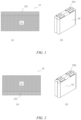
- Fig. 1 (a) shows a negative electrode plate according to an embodiment of the present application.
- the present application provides a negative electrode plate 10.
- the negative electrode plate 10 comprises a main body region 11 and a first low-thermal-conductivity edge region 121.
- the first low-thermal-conductivity edge region 121 and the main body region 11 respectively have thermal conductivities of ⁇ 2a and ⁇ 1 , where ⁇ 2a ⁇ ⁇ 1 .
- the negative electrode plate based on this solution is used for a secondary battery, and a lithium precipitation state of the secondary battery, especially a lithium precipitation state in an edge region, is effectively improved.
- the first low-thermal-conductivity edge region 121 is located on a side of the main body region 11.
- Fig. 1 (b) shows an electrode assembly according to an embodiment of the present application.
- an electrode assembly 52 comprises a wound core obtained by laminating and winding a negative electrode plate 10, a separator, and a positive electrode plate.
- the electrode assembly 52 further comprises a tab 522 mounted on a side of the negative electrode plate.
- the first low-thermal-conductivity edge region 121 is located on a side of the main body region 11 close to the tab 522.
- the electrode assembly based on this solution is used for a secondary battery, and a lithium precipitation state of the secondary battery, especially a lithium precipitation state in an edge region, is effectively improved.
- Fig. 2 (a) shows a negative electrode plate according to an embodiment of the present application.
- the present application provides a negative electrode plate 10.
- the negative electrode plate 10 comprises a main body region 11 and a second low-thermal-conductivity edge region 122.
- the second low-thermal-conductivity edge region 122 and the main body region 11 respectively have thermal conductivities of ⁇ 2b and ⁇ 1 , where ⁇ 2b ⁇ ⁇ 1 .
- the negative electrode plate based on this solution is used for a secondary battery, and a lithium precipitation state of the secondary battery, especially a lithium precipitation state in an edge region, is effectively improved.
- the second low-thermal-conductivity edge region 122 is located on a side of the main body region 11.
- Fig. 2 (b) shows an electrode assembly according to an embodiment of the present application.
- an electrode assembly 52 comprises a tab 522.
- the electrode assembly 52 comprises a wound core obtained by laminating and winding a negative electrode plate 10, a separator, and a positive electrode plate.
- the electrode assembly 52 further comprises a tab 522 mounted on a side of the negative electrode plate.
- the second low-thermal-conductivity edge region 122 is located on a side of the main body region 11 away from the tab 522.
- Fig. 3 (a) shows a negative electrode plate according to an embodiment of the present application.
- the negative electrode plate 10 comprises a main body region 11 and a low-thermal-conductivity edge region 12.
- the low-thermal-conductivity edge region 12 and the main body region 11 respectively have thermal conductivities of ⁇ 2 and ⁇ 1 , where ⁇ 2 ⁇ ⁇ 1 .
- the low-thermal-conductivity edge region 12 comprises a first low-thermal-conductivity edge region 121 and a second low-thermal-conductivity edge region 122.
- the first low-thermal-conductivity edge region 121 and the second low-thermal-conductivity edge region 122 are respectively located on two sides of the main body region 11.
- the first low-thermal-conductivity edge region 121, the second low-thermal-conductivity edge region 122, and the main body region 11 respectively have thermal conductivities of ⁇ 2a , ⁇ 2b , and ⁇ 1 , where ⁇ 2a ⁇ ⁇ 1 , and ⁇ 2b ⁇ ⁇ 1 .
- Fig. 3 (b) shows an electrode assembly according to an embodiment of the present application.
- an electrode assembly 52 comprises a wound core obtained by laminating and winding a negative electrode plate 10, a separator, and a positive electrode plate.
- the electrode assembly 52 further comprises a tab 522 mounted on a side of the negative electrode plate.
- the first low-thermal-conductivity edge region 121 is located on a side of the main body region 11 close to the tab 522
- the second low-thermal-conductivity edge region 122 is located on a side of the main body region 11 away from the tab 522.
- the main body region 11 and at least one low-thermal-conductivity edge region 12 are provided on the negative electrode plate 10, the thermal conductivities of the low-thermal-conductivity edge region 12 and the main body region 11 are respectively controlled to be ⁇ 2 and ⁇ 1 , where ⁇ 2 ⁇ ⁇ 1 .
- the negative electrode plate is used for a secondary battery, and a lithium precipitation state of the secondary battery, especially a lithium precipitation state in an edge region, is significantly improved.
- the reasoning is that the thermal conductivity of the low-thermal-conductivity edge region is different from that of the main body region (the former is less than the latter), and the temperature of the low-thermal-conductivity edge region is higher than that of the main body region during battery operation, so that dynamic performance of the low-thermal-conductivity edge region is greater than that of the main body region, thereby improving a lithium precipitation window of a negative electrode, suppressing lithium precipitation at an edge of the electrode plate, and improving battery cycling stability and safety.
- the negative electrode plate according to the present application is used for a secondary battery, and a lithium precipitation state of the secondary battery, especially a lithium precipitation state in an edge region, is effectively improved.
- the reasoning may be as follows: in the present application, it has been found that when a secondary battery (such as a lithium ion battery) is charged, Li + is deintercalated from the positive electrode, and the Li + diffuses to a negative electrode surface in the electrolyte and is intercalated in a negative electrode material.
- the low-thermal-conductivity edge region is creatively provided at the edge of the negative electrode plate. Because the low-thermal-conductivity edge region has a relatively low thermal conductivity, during operation of the secondary battery, the low-thermal-conductivity edge region has a higher temperature. This increases a diffusion and intercalation rate of Li + in the low-thermal-conductivity edge region, thereby improving the lithium precipitation state in the negative electrode edge region and further improving operation performance of the secondary battery.
- the term “low-thermal-conductivity” means that the edge region has a thermal conductivity less than that of the main body region, that is, the ratio of the thermal conductivity of the edge region to the thermal conductivity of the main body region is less than 1.
- the term “low-thermal-conductivity” does not indicate or imply a specific value which the thermal conductivity of the edge region must reach.
- the main body region 11 is a region near the center of the negative electrode plate 10
- the low-thermal-conductivity edge region refers to a region located outside the main body region 11 and having a thermal conductivity less than that of the main body region 11.
- edge region and the term “low-thermal-conductivity edge region” are used interchangeably.
- the thermal conductivity is obtained through testing based on "ISO 22007-2:2008 Determination of Thermal Conductivity of Material by Transient Plane Heat Source Method".
- the unit of a thermal conductivity may be W/(m ⁇ K).
- a direction in which a thermal conductivity is measured is optionally a face direction (i.e., normal direction) perpendicular to the negative electrode plate.
- a ratio ⁇ 1 / ⁇ 2 of the thermal conductivity ⁇ 1 to ⁇ 2 is 1.1-1.5 : 1, optionally 1.2-1.4 : 1, e.g., 1-1.1 : 1, 1.1-1.2 : 1, 1.2-1.3 : 1, 1.3-1.4 : 1, and 1.4-1.5 : 1.
- the negative electrode plate based on this solution is used for a secondary battery, and a lithium precipitation state of the secondary battery, especially a lithium precipitation state in an edge region, is further improved.
- the thermal conductivity ⁇ 1 has a value of 300-400 W/(m K), such as 300-320 W/(m ⁇ K), 320-340 W/(m ⁇ K), 340-360 W/(m K), 360-380 W/(m ⁇ K) or 380-400 W/(m ⁇ K).
- the negative electrode plate based on this solution is used for a secondary battery, and a lithium precipitation state of the secondary battery, especially a lithium precipitation state in an edge region, is further improved.
- the thermal conductivity ⁇ 2 has a value of 200-300 W/(m K), such as 200-220 W/(m ⁇ K), 220-240 W/(m ⁇ K), 240-260 W/(m K), 260-280 W/(m ⁇ K) or 280-300 W/(m ⁇ K).
- the negative electrode plate based on this solution is used for a secondary battery, and a lithium precipitation state of the secondary battery, especially a lithium precipitation state in an edge region, is further improved.
- the negative electrode plate based on this solution is used for a secondary battery, and a lithium precipitation state of the secondary battery, especially a lithium precipitation state in an edge region, is further improved.
- the electrical conductivity is obtained through testing with reference to the standard "GB/T 11007-2008 Test Method of Electrical Conductivity Analyzers".
- the unit of the electrical conductivity may be ⁇ S ⁇ cm -1 .
- a direction in which the electrical conductivity is measured may be optionally parallel to the negative electrode plate.
- a ratio ⁇ 1 / ⁇ 2 of the electrical conductivity ⁇ 1 to ⁇ 2 is 1.3 or less; optionally, ⁇ 1 / ⁇ 2 is 1-1.3 : 1; and optionally, ⁇ 1 / ⁇ 2 is 1.1-1.2 : 1.
- the negative electrode plate based on this solution is used for a secondary battery, and a lithium precipitation state of the secondary battery, especially a lithium precipitation state in an edge region, is further improved.
- the electrical conductivity ⁇ 1 has a value of 5.3 ⁇ 10 7 - 5.9 ⁇ 10 7 ⁇ S ⁇ cm -1 , such as 5.3-5.5 ⁇ S ⁇ cm -1 , 5.5-5.7 ⁇ S ⁇ cm -1 , and 5.7-5.9 ⁇ S ⁇ cm -1 .
- the negative electrode plate based on this solution is used for a secondary battery, and a lithium precipitation state of the secondary battery, especially a lithium precipitation state in an edge region, is further improved.
- the electrical conductivity ⁇ 2 has a value of 5.0 ⁇ 10 7 - 5.3 ⁇ 10 7 ⁇ S ⁇ cm -1 , such as 5.1-5.2 ⁇ S ⁇ cm -1 .
- the negative electrode plate based on this solution is used for a secondary battery, and a lithium precipitation state of the secondary battery, especially a lithium precipitation state in an edge region, is further improved.
- the negative electrode plate 10 has a length direction L and a width direction D, and a dimension of the negative electrode plate 10 in the length direction L is greater than that in the width direction D.
- the main body region 11 and the low-thermal-conductivity edge region 12 extend in the length direction L of the negative electrode plate 10.
- a distance between an inner side of the low-thermal-conductivity edge region 12 and an edge of the negative electrode plate 10 is w
- the negative electrode plate has a width of W
- a ratio W/w of W to w is equal to 11.5-21.9 : 1.
- the main body region 11 comprises a first long side 111 and a second long side 112 which are parallel to each other
- the negative electrode plate 10 comprises a first low-thermal-conductivity edge region 121 and/or a second low-thermal-conductivity edge region 122
- the first low-thermal-conductivity edge region 121 is located outside the first long side of the main body region 11
- the second low-thermal-conductivity edge region 122 is located outside the second long side of the main body region 11.
- the negative electrode plate based on this solution is used for a secondary battery, and a lithium precipitation state of the secondary battery, especially a lithium precipitation state in an edge region, is further improved.
- an outer side of the low-thermal-conductivity edge region 12 is next to an edge of the negative electrode plate 10.
- the negative electrode plate based on this solution is used for a secondary battery, and a lithium precipitation state of the secondary battery, especially a lithium precipitation state in an edge region, is further improved.
- the term "next to” includes that the outer side of the low-thermal-conductivity edge region completely coincides with the edge of the negative electrode plate 10, or there is a distance of only 5 mm or less (e.g., 3 mm or less) between the outer side of the low-thermal-conductivity edge region and the edge of the negative electrode plate.
- the negative electrode plate based on this solution is used for a secondary battery, and a lithium precipitation state of the secondary battery, especially a lithium precipitation state in an edge region, is further improved.
- the negative electrode plate based on this solution is used for a secondary battery, and a lithium precipitation state of the secondary battery, especially a lithium precipitation state in an edge region, is further improved.
- the negative electrode plate based on this solution is used for a secondary battery, and a lithium precipitation state of the secondary battery, especially a lithium precipitation state in an edge region, is further improved.
- an area of the main body region 11 accounts for 78.1%-88.5% of a unilateral area of the negative electrode plate 10, e.g., 78.1%-80.1%, 80.1%-82.1%, 82.1%-84.1%, 84.1%-86.1%, or 86.1%-88.1%.
- the negative electrode plate based on this solution is used for a secondary battery, and a lithium precipitation state of the secondary battery, especially a lithium precipitation state in an edge region, is further improved.
- an area of the low-thermal-conductivity edge region 12 accounts for 11.5%-21.9% of the unilateral area of the negative electrode plate 10, e.g., 11.5%-13.5%, 13.5%-15.5%, 15.5%-17.5%, 17.5%-19.5% or 19.5%-21.5%.
- the negative electrode plate based on this solution is used for a secondary battery, and a lithium precipitation state of the secondary battery, especially a lithium precipitation state in an edge region, is further improved.
- a ratio of the area of the main body region 11 to the area of the low-thermal-conductivity edge region 12 is 3.6-7.7 : 1, e.g., 3.6-4.6 : 1, 4.6-5.6 : 1, 5.6-6.6 : 1 or 6.6-7.6 : 1.
- the negative electrode plate based on this solution is used for a secondary battery, and a lithium precipitation state of the secondary battery, especially a lithium precipitation state in an edge region, is further improved.
- Fig. 4 shows a negative electrode plate according to some embodiments of the present application.
- an outer side of one or more sides of the main body region 11 is provided with a low-thermal-conductivity edge region 12.
- the negative electrode plate based on this solution is used for a secondary battery, and a lithium precipitation state of the secondary battery, especially a lithium precipitation state in an edge region, is further improved.
- the negative electrode plate 10 comprises a main body region 11 and a plurality of low-thermal-conductivity edge regions 12.
- the main body region 11 has a quadrangular shape. Outer sides of four sides of the main body region 11 are respectively provided with edge regions 12, which are sequentially a first low-thermal-conductivity edge region 121, a second low-thermal-conductivity edge region 122, a third low-thermal-conductivity edge region 123, and a fourth low-thermal-conductivity edge region 124.
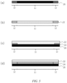
- Figs. 5 (a) - (d) show a negative electrode plate according to some embodiments of the present application.
- an embodiment of the present application provides a negative electrode plate 10, wherein the negative electrode plate 10 comprises a main body region 11 and at least one low-thermal-conductivity edge region 12; the low-thermal-conductivity edge region 12 and the main body region 11 respectively have thermal conductivities of ⁇ 2 and ⁇ 1 , where ⁇ 2 ⁇ ⁇ 1 .
- Figs. 5 (a) - (d) show cross-sectional diagrams of a negative electrode plate 10 according to some embodiments.
- the negative electrode plate 10 comprises a current collector layer 26, the current collector layer 26 belonging to the low-thermal-conductivity edge region 12 and the current collector layer 26 belonging to the main body region 11 respectively have thermal conductivities of ⁇ 21 and ⁇ 11 , where ⁇ 21 ⁇ ⁇ 11 .
- the negative electrode plate based on this solution is used for a secondary battery, and a lithium precipitation state of the secondary battery, especially a lithium precipitation state in an edge region, is further improved.
- the negative electrode plate 10 may further comprise an active material layer laminated with the current collector layer 26.
- the negative electrode plate 10 comprises an active material layer 22, and the negative electrode active material layer 22 belonging to the low-thermal-conductivity edge region 12 and the negative electrode active material layer 22 belonging to the main body region 11 respectively have thermal conductivities of ⁇ 23 and ⁇ 13 , where ⁇ 23 ⁇ ⁇ 13 .
- the negative electrode plate based on this solution is used for a secondary battery, and a lithium precipitation state of the secondary battery, especially a lithium precipitation state in an edge region, is further improved.
- the negative electrode plate 10 may further comprise a current collector layer laminated with the active material layer.
- the negative electrode plate 10 comprises a current collector layer 26 and an active material layer 22, wherein a priming coat 24 belonging to the low-thermal-conductivity edge region 12 is further provided between the current collector layer 26 belonging to the low-thermal-conductivity edge region 12 and the active material layer 22 belonging to the low-thermal-conductivity edge region 12; and the active material layer 22 belonging to the main body region 11 is directly laminated on the current collector layer 26 belonging to the main body region 11 (that is, no priming coat 24 is provided between the active material layer belonging to the main body region and the current collector layer belonging to the main body region).
- the negative electrode plate based on this solution is used for a secondary battery, and a lithium precipitation state of the secondary battery, especially a lithium precipitation state in an edge region, is further improved.
- the negative electrode plate 10 comprises a current collector layer 26 and an active material layer 22, wherein a priming coat 24 belonging to the low-thermal-conductivity edge region 12 is further provided between the current collector layer 26 belonging to the low-thermal-conductivity edge region 12 and the active material layer 22 belonging to the low-thermal-conductivity edge region 12; a priming coat 24 belonging to the main body region 11 is further provided between the current collector layer 26 belonging to the main body region 11 and the active material layer 22 belonging to the low-thermal-conductivity edge region 12; and the priming coat 24 belonging to the low-thermal-conductivity edge region 12 and the priming coat 24 belonging to the main body region 11 respectively have thermal conductivities of ⁇ 22 and ⁇ 12 , where ⁇ 22 ⁇ ⁇ 12 .
- the negative electrode plate based on this solution is used for a secondary battery, and a lithium precipitation state of the secondary battery, especially a lithium precipitation state in an edge region, is further improved
- the priming coat 24 belonging to the low-thermal-conductivity edge region 12 comprises a thermal resistance material
- the priming coat 24 belonging to the main body region 11 comprises conductive carbon black
- the thermal resistance material has a thermal conductivity less than that of the conductive carbon black.
- the priming coat 24 belonging to the main body region 11 does not comprise the thermal resistance material.
- the negative electrode plate based on this solution is used for a secondary battery, and a lithium precipitation state of the secondary battery, especially a lithium precipitation state in an edge region, is further improved.
- the priming coat 24 belonging to the main body region 11 comprises the thermal resistance material, but the content of the thermal resistance material in the priming coat 24 belonging to the main body region 11 is less than that in the priming coat 24 belonging to the low-thermal-conductivity edge region 12.
- the negative electrode plate based on this solution is used for a secondary battery, and a lithium precipitation state of the secondary battery, especially a lithium precipitation state in an edge region, is further improved.
- the priming coat 24 belonging to the low-thermal-conductivity edge region 12 comprises the following components: 50wt%-60wt% (e.g., 53wt%-55wt%) of conductive carbon black; 5wt%-15wt% (e.g., 8wt%-12wt%, e.g. 10wt%) of thermal resistance material; and 30wt%-40wt% (e.g., 31wt%-34wt%) of binder.
- the negative electrode plate based on this solution is used for a secondary battery, and a lithium precipitation state of the secondary battery, especially a lithium precipitation state in an edge region, is further improved.
- the binder in the priming coat 24 belonging to the low-thermal-conductivity edge region 12 is styrene butadiene rubber.
- the priming coat 24 belonging to the low-thermal-conductivity edge region 12 further comprises 0.01wt%-0.1wt% of dispersant.
- the dispersant is carboxymethyl cellulose.
- the priming coat 24 belonging to the main body region 11 comprises the following components: 60wt%-70wt% of conductive carbon black; and 30wt%-40wt% of binder.
- the negative electrode plate based on this solution is used for a secondary battery, and a lithium precipitation state of the secondary battery, especially a lithium precipitation state in an edge region, is further improved.
- the binder in the priming coat 24 belonging to the main body region 11 is styrene butadiene rubber.
- the priming coat 24 belonging to the main body region 11 further comprises 0.01wt%-0.1wt% of dispersant.
- the dispersant is carboxymethyl cellulose.
- the thermal resistance material is selected from one or more of the following: gelatin, ammonium sulfate, ammonium chloride, thiourea, and copper chloride.
- the negative electrode plate based on this solution is used for a secondary battery, and a lithium precipitation state of the secondary battery, especially a lithium precipitation state in an edge region, is further improved.
- the negative electrode plate is a negative electrode without a current collector.
- the negative electrode plate comprises a negative electrode current collector and a negative electrode active material layer provided on at least one surface of the negative electrode current collector, the negative electrode active material layer comprising a negative electrode active material.
- the negative electrode current collector has two opposite surfaces in its own thickness direction, and the negative electrode active material layer is provided on either or both of the two opposite surfaces of the negative electrode current collector.
- the negative electrode current collector may be a metal foil or a composite current collector.
- a metal foil a copper foil can be used.
- the composite current collector may comprise a polymer material substrate and a metal layer formed on at least one surface of the polymer material substrate.
- the composite current collector can be formed by forming a metal material (copper, a copper alloy, nickel, a nickel alloy, titanium, a titanium alloy, silver and a silver alloy, etc.) on a polymer material substrate (e.g., polypropylene (PP), polyethylene terephthalate (PET), polybutylene terephthalate (PBT), polystyrene (PS), polyethylene (PE), etc.).
- PP polypropylene
- PET polyethylene terephthalate
- PBT polybutylene terephthalate
- PS polystyrene
- PE polyethylene
- the negative electrode active material can be a negative electrode active material known in the art for batteries.
- the negative electrode active material may include at least one of the following materials: artificial graphite, natural graphite, soft carbon, hard carbon, a silicon-based material, a tin-based material and lithium titanate, etc.
- the silicon-based material may be selected from at least one of elemental silicon, silicon oxides, silicon carbon composites, silicon nitrogen composites and silicon alloys.
- the tin-based material may be selected from at least one of elemental tin, tin oxides, and tin alloys.
- the present application is not limited to these materials, and other conventional materials that can be used as negative electrode active materials for batteries can also be used. These negative electrode active materials may be used alone or in combination of two or more.
- the negative electrode active material layer also optionally comprises a binder.
- the binder may be selected from at least one of a styrene butadiene rubber (SBR), polyacrylic acid (PAA), sodium polyacrylate (PAAS), polyacrylamide (PAM), polyvinyl alcohol (PVA), sodium alginate (SA), polymethacrylic acid (PMAA), and carboxymethyl chitosan (CMCS).
- SBR styrene butadiene rubber
- PAA polyacrylic acid
- PAAS sodium polyacrylate
- PAM polyacrylamide
- PVA polyvinyl alcohol
- SA sodium alginate
- PMAA polymethacrylic acid
- CMCS carboxymethyl chitosan
- the negative electrode active material layer also optionally comprises a conductive agent.
- the conductive agent may be selected from at least one of superconductive carbon, acetylene black, carbon black, ketjenblack, carbon dots, carbon nanotubes, graphene, and carbon nanofibers.
- the negative electrode active material layer also optionally comprises other auxiliary agents, e.g., a thickener (e.g. sodium carboxymethyl cellulose (CMC-Na)).
- a thickener e.g. sodium carboxymethyl cellulose (CMC-Na)
- the negative electrode plate can be prepared as follows: the above-mentioned components for preparing the negative electrode plate, such as the negative electrode active material, the conductive agent, the binder and any other components, are dispersed in a solvent (e.g. deionized water) to form a negative electrode slurry; and the negative electrode slurry is coated onto a negative electrode current collector, and is then subjected to procedures such as drying and cold pressing, so as to obtain the negative electrode plate.
- a solvent e.g. deionized water
- the electrolyte is located between the positive electrode plate and the negative electrode plate and functions for ionic conduction.
- the type of the electrolyte is not specifically limited in the present application, and can be selected according to actual requirements.
- the electrolyte may be liquid, gel or all solid.
- the electrolyte is liquid and includes an electrolyte salt and a solvent.
- the electrolyte salt may be selected from at least one of lithium hexafluorophosphate, lithium tetrafluoroborate, lithium perchlorate, lithium hexafluoroarsenate, lithium bisfluorosulfonimide, lithium bistrifluoromethanesulfonimide, lithium trifluoromethanesulfonate, lithium difluorophosphate, lithium difluorooxalate borate, lithium dioxalate borate, lithium difluorodioxalate phosphate and lithium tetrafluorooxalate phosphate.
- the solvent may be selected from at least one of ethylene carbonate, propylene carbonate, ethyl methyl carbonate, diethyl carbonate, dimethyl carbonate, dipropyl carbonate, methyl propyl carbonate, ethyl propyl carbonate, butylene carbonate, fluoroethylene carbonate, methyl formate, methyl acetate, ethyl acetate, propyl acetate, methyl propionate, ethyl propionate, propyl propionate, methyl butyrate, ethyl butyrate, 1,4-butyrolactone, sulfolane, dimethyl sulfone, ethyl methyl sulfone, and diethyl sulfone.
- the electrolyte further optionally comprises an additive.
- the additive may include a negative electrode film-forming additive and a positive electrode film-forming additive, and may further include an additive that can improve some performance of the battery, such as an additive that improves overcharge performance of the battery, or an additive that improves high-temperature performance or low-temperature performance of the battery.
- the secondary battery further comprises a separator.
- the type of the separator is not particularly limited in the present application, and any well-known porous-structure separator with good chemical stability and mechanical stability may be selected.
- the material of the separator may be selected from at least one of glass fibers, non-woven fabrics, polyethylene, polypropylene, and polyvinylidene fluoride.
- the separator may be a single-layer film and also a multi-layer composite film, and is not limited particularly. When the separator is a multi-layer composite film, the materials in the respective layers may be the same or different, which is not limited particularly.
- a positive electrode plate, a negative electrode plate and a separator can be subjected to a winding process or a laminating process to form an electrode assembly.
- an embodiment of the present application provides a secondary battery, comprising an electrode assembly, wherein the electrode assembly comprises the negative electrode plate according to any one of the above embodiments.
- the shape of the secondary battery is not particularly limited in the present application, and may be cylindrical, square or of any other shape.
- Fig. 6 shows a secondary battery 5 with a square structure as an example.
- an outer package may comprise a housing 51 and a cover plate 53.
- the housing 51 may comprise a bottom plate and side plates connected to the bottom plate, and the bottom plate and the side plates enclose to form an accommodating cavity.
- the housing 51 has an opening in communication with the accommodating cavity, and the cover plate 53 can cover the opening to close the accommodating cavity.
- the positive electrode plate, the negative electrode plate and the separator can be subjected to a winding process or a laminating process to form an electrode assembly 52.
- the electrode assembly 52 is encapsulated in the accommodating cavity.
- the electrolyte is infiltrated into the electrode assembly 52.
- the number of the electrode assemblies 52 contained in the secondary battery 5 may be one or more, and can be selected by those skilled in the art according to actual requirements.
- a positive electrode plate, a negative electrode plate and a separator can be subjected to a winding process or a laminating process to form an electrode assembly.
- the secondary battery may comprise an outer package.
- the outer package can be used to encapsulate the above-mentioned electrode assembly and electrolyte.
- the outer package of the secondary battery can be a hard shell, for example, a hard plastic shell, an aluminum shell, a steel shell, etc.
- the outer package of the secondary battery may also be a soft bag, such as a pouch-type soft bag.
- the material of the soft bag may be plastics, and the examples of plastics may include polypropylene, polybutylene terephthalate, and polybutylene succinate, etc.
- the secondary battery can be assembled into a battery module, and the number of the secondary batteries contained in the battery module may be one or more, and the specific number can be selected by those skilled in the art according to the application and capacity of the battery module.
- an embodiment of the present application provides a battery module, comprising the secondary battery according to any one of the above embodiments.
- Fig. 7 shows a battery module 4 as an example.
- a plurality of secondary batteries 5 may be arranged in sequence in the length direction of the battery module 4. It will be apparent that the secondary batteries may also be arranged in any other manner. Furthermore, the plurality of secondary batteries 5 may be fixed by fasteners.
- the battery module 4 may also comprise a housing with an accommodating space, and a plurality of secondary batteries 5 are accommodated in the accommodating space.
- the above-mentioned battery module may also be assembled into a battery pack, the number of battery modules included in the battery pack may be one or more, and the specific number can be selected by those skilled in the art according to the application and capacity of the battery pack.
- an embodiment of the present application provides a battery pack, comprising the battery module according to any one of the above embodiments.
- the battery pack 1 may comprise a battery box and a plurality of battery modules 4 provided in the battery box.
- the battery box comprises an upper box body 2 and a lower box body 3, wherein the upper box body 2 can cover the lower box body 3 to form a closed space for accommodating the battery modules 4.
- a plurality of battery modules 4 may be arranged in the battery box in any manner.
- an embodiment of the present application provides a power consuming device, comprising at least one selected from the secondary battery according to any one of the above embodiments, the battery module according to any one of the above embodiments or the battery pack according to any one of the above embodiments.
- the secondary battery, battery module or battery pack may be used as a power source of the power consuming device or as an energy storage unit of the power consuming device.
- the power consuming device may include a mobile device (e.g., a mobile phone, a laptop computer, etc.), an electric vehicle (e.g., a battery electric vehicle, a hybrid electric vehicle, a plug-in hybrid electric vehicle, an electric bicycle, an electric scooter, an electric golf cart, an electric truck, etc.), an electric train, a ship, a satellite, an energy storage system, etc., but is not limited thereto.
- Fig. 10 shows a power consuming device as an example.
- the power consuming device may be a pure electric vehicle, a hybrid electric vehicle, a plug-in hybrid electric vehicle or the like.
- a battery pack or a battery module may be used.
- a copper foil was provided as a negative electrode current collector, and the copper foil had the following dimensions: a thickness of 6 ⁇ m, a length of 2545 mm, and a width of 183 mm.
- Coating of a priming coat on a first side the surface of the first side of the negative electrode current collector was divided into a main body region and two low-thermal-conductivity edge regions. Both the main body region and the two low-thermal-conductivity edge regions extended in a length direction of the negative electrode current collector.
- the two low-thermal-conductivity edge regions were located on two sides of a long side of the main body region.
- the main body region had dimensions of 2545 mm ⁇ 163 mm.
- the two low-thermal-conductivity edge regions each had dimensions of 2545 mm ⁇ 10 mm.
- a gravure coating process was used to respectively apply the priming coat slurry of the main body region and the priming coat slurry of the low-thermal-conductivity edge regions to the main body region and the low-thermal-conductivity edge regions, with a coating thickness of 129 ⁇ m. After the coating, the priming coat slurry was dried in an oven at 100°C for 6 h.
- Coating of a priming coat on a second side the same partitioning and coating treatment was used as that of the surface of the first side, and the priming coat was applied to the surface of the second side of the negative electrode current collector.
- the current collector with the priming coat was obtained.
- a method for preparing a negative electrode active slurry was as follows: graphite/hard carbon, SBR (as a binder) and CMC (as a dispersant) were mixed at a weight percentage ratio of 97% : 1% : 2%, diluted with an appropriate amount of distilled water, and then stirred in a vacuum mixer to form a uniform negative electrode active slurry.
- the negative electrode active slurry prepared in step (2) was applied to the surface of the first side of the current collector with the priming coat. After the coating, the negative electrode active slurry was dried in an oven at 100°C for 6 h.
- the same process for coating of the negative electrode active slurry as that of the first side was used for the coating of the second side, to coat the surface of the second side of the current collector with the priming coat. After the coating, the negative electrode active slurry was dried in an oven at 100°C for 6 h.
- the negative electrode plate of Example 1 was obtained. On a single side basis, the negative electrode active material had a load of 0.160 g/1540.25 mm 2 .
- Positive electrode active materials LiNi 0.33 Co 0.33 Mn 0.33 O 2 , SP and PVDF were mixed at a weight percentage ratio of 97% : 1.5% : 1.5%, diluted with an appropriate amount of N-methylpyrrolidone, and then stirred in a vacuum mixer to form a uniform positive electrode active slurry.
- a copper foil was provided as a positive electrode current collector.
- the positive electrode current collector had the following dimensions: a thickness of 13 ⁇ m, a length of 2460 mm, and a width of 179 mm.
- the positive electrode active slurry was applied to a first side of the positive electrode current collector for single-side coating. After the coating, the positive electrode active slurry was dried in an oven at 100°C for 6 h. Then the positive electrode active slurry was coated on a second side of the positive electrode current collector for single-side coating. After the coating, the positive electrode active slurry was dried in an oven at 100°C for 6 h. The positive electrode plate of Example 1 was obtained. On a single side basis, the positive electrode active material had a load of 0.304 g/1540.25 mm 2 .
- Tabs were respectively mounted on a long side of the positive electrode plate and a long side of the negative electrode plate, and then were sequentially laminated and wound with a separator to form a wound core, i.e., an electrode assembly (with dimensions of 28 cm ⁇ 148 cm ⁇ 118 cm).
- a first low-thermal-conductivity edge region was a low-thermal-conductivity edge region close to the tab, and a second low-thermal-conductivity edge region was a low-thermal-conductivity edge region away from the tab.
- the electrode assembly was placed in an outer package, and 150 g of electrolyte was injected.
- the electrolyte was a solution containing 1 M LiPF 6 , and a solvent of the solution was a product obtained by mixing EC, DEC and DMC at a volume ratio of 1 : 1 : 1. After packaging with the outer package, a secondary battery was obtained.
- the negative electrode active material had a load of 96.76 g, and the positive electrode active material had a load of 173.8 g.
- Example 2 differed from Example 1 only in a formula of a priming coat slurry in a low-thermal-conductivity edge region.
- Example 3 differed from Example 1 in a formula of a priming coat slurry in a low-thermal-conductivity edge region.
- Example 4 differed from Example 1 in (1) - (2) as follows:
- a copper foil was provided as a negative electrode current collector, and the copper foil had the following dimensions: a thickness of 6 ⁇ m, a length of 2545 mm, and a width of 183 mm.
- Coating of a priming coat on a first side the surface of the first side of the negative electrode current collector was divided into a main body region and a first low-thermal-conductivity edge region. Both the main body region and the first low-thermal-conductivity edge region extended in a length direction of the negative electrode current collector.
- the first low-thermal-conductivity edge region was located on a side of a first long side (a long side for subsequently mounting a tab) of the main body region.
- the main body region had dimensions of 2545 mm ⁇ 173 mm.
- the first low-thermal-conductivity edge region had dimensions of 2545 mm ⁇ 10 mm.
- a gravure coating process was used to respectively apply the priming coat slurry of the main body region and the priming coat slurry of the low-thermal-conductivity edge region to the main body region and the low-thermal-conductivity edge region, with a coating thickness of 129 ⁇ m. After the coating, the priming coat slurry was dried in an oven at 100°C for 6 h.
- Coating of a priming coat on a second side the same partitioning and coating treatment was used as that of the surface of the first side, and the priming coat was applied to the surface of the second side of the negative electrode current collector.
- the current collector with the priming coat was obtained.
- Example 5 differed from Example 1 in (1) - (2) as follows:
- a copper foil was provided as a negative electrode current collector, and the copper foil had the following dimensions: a thickness of 6 ⁇ m, a length of 2545 mm, and a width of 183 mm.
- Coating of a priming coat on a first side the surface of the first side of the negative electrode current collector was divided into a main body region and a second low-thermal-conductivity edge region. Both the main body region and the second low-thermal-conductivity edge region extended in a length direction of the negative electrode current collector.
- the first low-thermal-conductivity edge region was located on a side of a second long side (a long side away from the tab) of the main body region.
- the main body region had dimensions of 2545 mm ⁇ 173 mm.
- the second low-thermal-conductivity edge region had dimensions of 2545 mm ⁇ 10 mm.
- a gravure coating process was used to respectively apply the priming coat slurry of the main body region and the priming coat slurry of the low-thermal-conductivity edge region to the main body region and the low-thermal-conductivity edge region, with a coating thickness of 129 ⁇ m. After the coating, the priming coat slurry was dried in an oven at 100°C for 6 h.
- Coating of a priming coat on a second side the same partitioning and coating treatment was used as that of the surface of the first side, and the priming coat was applied to the surface of the second side of the negative electrode current collector.
- the current collector with the priming coat was obtained.
- Comparative Example 1 differed from Example 1 as follows: in step 1.2 of Comparative Example 1, no partitioned coating of a negative electrode priming coat was provided. Details were as follows: a copper foil was provided as a negative electrode current collector, and the copper foil had the following dimensions: a thickness of 6 ⁇ m, a length of 2545 mm, and a width of 183 mm. A gravure coating process was used to apply the priming coat slurry of the main body region to surfaces of two sides of the negative electrode current collector, with a coating thickness of 129 ⁇ m. After the coating, the priming coat slurry was dried in an oven at 100°C for 6 h. After the coating, the current collector with the priming coat was obtained.
- Thermal conductivities of the low-thermal-conductivity edge region and the main body region of the negative electrode plate were detected with reference to the standard "ISO 22007-2:2008 Determination of Thermal Conductivity of Material by Transient Plane Heat Source Method".
- thermal conductivities of the main body region, the first low-thermal-conductivity edge region and the second low-thermal-conductivity edge region were separately detected, and named ⁇ 1 , ⁇ 2a , and ⁇ 2b .
- thermal conductivities of the main body region and the first low-thermal-conductivity edge region were separately detected, and named ⁇ 1 and ⁇ 2a .
- thermal conductivities of the main body region and the second low-thermal-conductivity edge region were separately detected, and named ⁇ 1 and ⁇ 2b .
- An electrode plate was cut with a stamping knife, with cut positions respectively located in the low-thermal-conductivity edge region (a region which was 10 mm from the edge of the negative electrode plate) and the main body region (a region near the center of the electrode plate).
- Samples of 5 mm (horizontal) * 7 mm (vertical) were extracted in the long-side direction (MD direction) by using the stamping knife.
- a testing instrument was a two-probe diaphragm resistance tester. Test results are shown in Table 1.
- thermal conductivities of the main body region, the first low-thermal-conductivity edge region and the second low-thermal-conductivity edge region were separately detected, and named ⁇ 1 , ⁇ 2a , and ⁇ 2b .
- thermal conductivities of the main body region and the first low-thermal-conductivity edge region were separately detected, and named ⁇ 1 and ⁇ 2a .
- thermal conductivities of the main body region and the second low-thermal-conductivity edge region were separately detected, and named ⁇ 1 and ⁇ 2b . 3.
- a method for evaluating the lithium precipitation degree is as follows:
- Samples were cut from the negative electrode plates in Examples 1-5 and Comparative Example 1 and then elongated, and the elongated samples had a gauge length of 50 mm and a width of 20 mm.
- Examples 1-3 of Table 1 when the first low-thermal-conductivity edge region and the second low-thermal-conductivity edge region were provided on the negative electrode plate of the secondary battery, the first low-thermal-conductivity edge region and the second low-thermal-conductivity edge region had thermal conductivities less than that of the main body region, and the secondary batteries of Examples 1-3 had excellent performance without lithium precipitation.
- Examples 4-5 of Table 1 when the first low-thermal-conductivity edge region or the second low-thermal-conductivity edge region was provided on the negative electrode plate of the secondary battery, the first low-thermal-conductivity edge region and the second low-thermal-conductivity edge region had thermal conductivities less than that of the main body region, and the secondary batteries of Examples 4-5 had good performance with only primary lithium precipitation.
- the reasoning for the improvement of a lithium precipitation state of the secondary battery in Examples 1-5 without being limited by theory may be as follows: firstly, in the present application, it has been found that when a secondary battery (such as a lithium ion battery) is charged, Li + is deintercalated from the positive electrode, and the Li + diffuses to the negative electrode surface in the electrolyte and are intercalated in a negative electrode material. However, due to obstruction of ohmic resistance and a charge transfer and diffusion process, some Li + cannot be smoothly inserted into the negative electrode material, so that a side reaction of lithium deposition, i.e., lithium precipitation, occurs on the surface of the negative electrode plate.
- a secondary battery such as a lithium ion battery
- the low-thermal-conductivity edge region is creatively provided at the edge of the negative electrode plate. Therefore, during operation of the secondary battery, the low-thermal-conductivity edge region has a greater temperature. This improves the diffusion and intercalation process of Li + , and then improves the lithium precipitation state of the negative electrode, especially the lithium precipitation state in the edge region.
- Examples 1-3 of Table 1 when the first low-thermal-conductivity edge region and the second low-thermal-conductivity edge region were provided on the negative electrode plate of the secondary battery, the first low-thermal-conductivity edge region and the second low-thermal-conductivity edge region had thermal conductivities less than that of the main body region, and the secondary batteries of Examples 1-3 had excellent mechanical properties, with the elongation of 0.6.
- Examples 4-5 of Table 1 when the first low-thermal-conductivity edge region or the second low-thermal-conductivity edge region was provided on the negative electrode plate of the secondary battery, the first low-thermal-conductivity edge region and the second low-thermal-conductivity edge region had thermal conductivities less than that of the main body region, and the negative electrode plates of Examples 4-5 had good mechanical properties, with the elongation of 0.7-0.9.
- Comparative Example 1 of Table 1 when neither the first low-thermal-conductivity edge region nor the second low-thermal-conductivity edge region was provided on the negative electrode plate of the secondary battery, the mechanical properties of the secondary battery of Comparative Example 1 were not so good as those of Examples 1-5, with the elongation of 0.5.
Landscapes
- Chemical & Material Sciences (AREA)
- Chemical Kinetics & Catalysis (AREA)
- Electrochemistry (AREA)
- General Chemical & Material Sciences (AREA)
- Engineering & Computer Science (AREA)
- Materials Engineering (AREA)
- Manufacturing & Machinery (AREA)
- Composite Materials (AREA)
- Battery Electrode And Active Subsutance (AREA)
- Secondary Cells (AREA)
Abstract
Description
- The present application relates to the technical field of secondary batteries, and in particular, to a negative electrode plate, a secondary battery, a battery module, a battery pack, and a power consuming device.
- In recent years, with an increasing range of applications, secondary batteries are widely used in energy storage power systems such as hydraulic power, thermal power, wind power and solar power stations, as well as many fields such as electric tools, electric bicycles, electric motorcycles, electric vehicles, military equipment, and aerospace. Due to the great development of secondary batteries, higher requirements have also been placed on secondary batteries in terms of energy density, cycling performance, safety performance, etc.
- The present application is implemented in view of the above problems, and an objective thereof is to provide a negative electrode plate, wherein the negative electrode plate comprises a main body region and at least one low-thermal-conductivity edge region; and the low-thermal-conductivity edge region and the main body region respectively have thermal conductivities of λ2 and λ1, where λ2 < λ1. The negative electrode plate based on this solution is used for a secondary battery, and a lithium precipitation state of the secondary battery, especially a lithium precipitation state in an edge region, is effectively improved.
- In some embodiments, a ratio λ1/λ2 of λ1 to λ2 is 1.1-1.5 : 1. The negative electrode plate based on this solution is used for a secondary battery, and a lithium precipitation state of the secondary battery, especially a lithium precipitation state in an edge region, is further improved.
- In some embodiments, λ1 has a value of 300-400 W/(m K). The negative electrode plate based on this solution is used for a secondary battery, and a lithium precipitation state of the secondary battery, especially a lithium precipitation state in an edge region, is further improved.
- In some embodiments, λ2 has a value of 200-300 W/(m K). The negative electrode plate based on this solution is used for a secondary battery, and a lithium precipitation state of the secondary battery, especially a lithium precipitation state in an edge region, is further improved.
- In some embodiments, the low-thermal-conductivity edge region and the main body region respectively have electrical conductivities of σ2 and σ1; the negative electrode plate meets a kinetic coefficient Q > 0, and the kinetic coefficient Q is calculated by using the following formula:

- In some embodiments, a ratio σ1/σ2 of σ1 to σ2 is 1.3 or less, optionally 1-1.3 : 1. The negative electrode plate based on this solution is used for a secondary battery, and a lithium precipitation state of the secondary battery, especially a lithium precipitation state in an edge region, is further improved.
- In some embodiments, σ1 has a value of 5.3 × 10⁷ - 5.9 × 10⁷ µS·cm-1. The negative electrode plate based on this solution is used for a secondary battery, and a lithium precipitation state of the secondary battery, especially a lithium precipitation state in an edge region, is further improved.
- In some embodiments, σ2 has a value of 5.0 × 10⁷ - 5.3 × 10⁷ µS·cm-1. The negative electrode plate based on this solution is used for a secondary battery, and a lithium precipitation state of the secondary battery, especially a lithium precipitation state in an edge region, is further improved.
- In some embodiments, the negative electrode plate comprises a current collector layer, the current collector layer belonging to the low-thermal-conductivity edge region and the current collector layer belonging to the main body region respectively have thermal conductivities of λ21 and λ11, where λ21 < λ11. The negative electrode plate based on this solution is used for a secondary battery, and a lithium precipitation state of the secondary battery, especially a lithium precipitation state in an edge region, is further improved.
- In some embodiments, the negative electrode plate comprises an active material layer, the negative electrode active material layer belonging to the low-thermal-conductivity edge region and the negative electrode active material layer belonging to the main body region respectively have thermal conductivities of λ23 and λ13, where λ23 < λ13. The negative electrode plate based on this solution is used for a secondary battery, and a lithium precipitation state of the secondary battery, especially a lithium precipitation state in an edge region, is further improved.
- In some embodiments, the negative electrode plate comprises a current collector layer and an active material layer, wherein a priming coat belonging to the low-thermal-conductivity edge region is further provided between the current collector layer belonging to the low-thermal-conductivity edge region and the active material layer belonging to the low-thermal-conductivity edge region; and the active material layer belonging to the main body region is directly laminated on the current collector layer belonging to the main body region (that is, no priming coat is provided between the active material layer belonging to the main body region and the current collector layer belonging to the main body region). The negative electrode plate based on this solution is used for a secondary battery, and a lithium precipitation state of the secondary battery, especially a lithium precipitation state in an edge region, is further improved.
- In some embodiments, the negative electrode plate comprises a current collector layer and an active material layer, wherein a priming coat belonging to the low-thermal-conductivity edge region is further provided between the current collector layer belonging to the low-thermal-conductivity edge region and the active material layer belonging to the low-thermal-conductivity edge region; and a priming coat belonging to the main body region is further provided between the current collector layer belonging to the main body region and the active material layer belonging to the low-thermal-conductivity edge region; and the priming coat belonging to the low-thermal-conductivity edge region and the priming coat belonging to the main body region respectively have thermal conductivities of λ22 and λ12, where λ22 < λ12. The negative electrode plate based on this solution is used for a secondary battery, and a lithium precipitation state of the secondary battery, especially a lithium precipitation state in an edge region, is further improved.
- In some embodiments, the priming coat belonging to the low-thermal-conductivity edge region comprises a thermal resistance material, the priming coat belonging to the main body region comprises conductive carbon black, and the thermal resistance material has a thermal conductivity less than that of the conductive carbon black. The negative electrode plate based on this solution is used for a secondary battery, and a lithium precipitation state of the secondary battery, especially a lithium precipitation state in an edge region, is further improved.
- In some embodiments, the priming coat belonging to the main body region does not comprise the thermal resistance material. The negative electrode plate based on this solution is used for a secondary battery, and a lithium precipitation state of the secondary battery, especially a lithium precipitation state in an edge region, is further improved.
- In some embodiments, the priming coat belonging to the main body region comprises the thermal resistance material, but the content of the thermal resistance material in the priming coat belonging to the main body region is less than that in the priming coat belonging to the low-thermal-conductivity edge region. The negative electrode plate based on this solution is used for a secondary battery, and a lithium precipitation state of the secondary battery, especially a lithium precipitation state in an edge region, is further improved.
- In some embodiments, the priming coat belonging to the low-thermal-conductivity edge region comprises the following components: 50 wt%-60 wt% of conductive carbon black; 5 wt%-15 wt% of thermal resistance material; and 30 wt%-40 wt% of binder. The negative electrode plate based on this solution is used for a secondary battery, and a lithium precipitation state of the secondary battery, especially a lithium precipitation state in an edge region, is further improved.
- In some embodiments, the priming coat belonging to the main body region comprises the following components: 60 wt%-70 wt% of conductive carbon black; and 30 wt%-40 wt% of binder. The negative electrode plate based on this solution is used for a secondary battery, and a lithium precipitation state of the secondary battery, especially a lithium precipitation state in an edge region, is further improved.
- In some embodiments, the thermal resistance material is selected from one or more of the following: gelatin, ammonium sulfate, ammonium chloride, thiourea, and copper chloride. The negative electrode plate based on this solution is used for a secondary battery, and a lithium precipitation state of the secondary battery, especially a lithium precipitation state in an edge region, is further improved.
- In some embodiments, the negative electrode plate comprises a first low-thermal-conductivity edge region and/or a second low-thermal-conductivity edge region, and the main body region comprises a first long side and a second long side which are parallel to each other; the first low-thermal-conductivity edge region is located outside the first long side of the main body region; and the second low-thermal-conductivity edge region is located outside the second long side of the main body region. In this implementation solution, the main body region has a length-width ratio greater than 1, e.g., a length-width ratio greater than 2.
- In some embodiments, an outer side of the low-thermal-conductivity edge region is next to an edge of the negative electrode plate. The negative electrode plate based on this solution is used for a secondary battery, and a lithium precipitation state of the secondary battery, especially a lithium precipitation state in an edge region, is further improved.
- In some embodiments, a distance between an inner side of the low-thermal-conductivity edge region and an edge of the negative electrode plate is w, the negative electrode plate has a width of W, and a ratio W/w of W to w is equal to 11.5-21.9 : 1. The negative electrode plate based on this solution is used for a secondary battery, and a lithium precipitation state of the secondary battery, especially a lithium precipitation state in an edge region, is further improved.
- In some embodiments, w = 8-15 mm. The negative electrode plate based on this solution is used for a secondary battery, and a lithium precipitation state of the secondary battery, especially a lithium precipitation state in an edge region, is further improved.
- In some embodiments, W = 100-200 mm. The negative electrode plate based on this solution is used for a secondary battery, and a lithium precipitation state of the secondary battery, especially a lithium precipitation state in an edge region, is further improved.
- In some embodiments, an outer side of one or more sides of the main body region is provided with a low-thermal-conductivity edge region. The negative electrode plate based on this solution is used for a secondary battery, and a lithium precipitation state of the secondary battery, especially a lithium precipitation state in an edge region, is further improved.
- In some embodiments, an area of the main body region accounts for 78.1%-88.5% of a unilateral area of the negative electrode plate. The negative electrode plate based on this solution is used for a secondary battery, and a lithium precipitation state of the secondary battery, especially a lithium precipitation state in an edge region, is further improved.
- In some embodiments, an area of the low-thermal-conductivity edge region accounts for 11.5%-21.9% of the unilateral area of the negative electrode plate. The negative electrode plate based on this solution is used for a secondary battery, and a lithium precipitation state of the secondary battery, especially a lithium precipitation state in an edge region, is further improved.
- In some embodiments, a ratio of the area of the main body region to the area of the low-thermal-conductivity edge region is 3.6-7.7 : 1. The negative electrode plate based on this solution is used for a secondary battery, and a lithium precipitation state of the secondary battery, especially a lithium precipitation state in an edge region, is further improved.
- An embodiment of the present application provides a secondary battery, comprising an electrode assembly, wherein the electrode assembly comprises the negative electrode plate according to any one of the above embodiments.
- An embodiment of the present application provides a battery module, comprising the secondary battery according to any one of the above embodiments.
- An embodiment of the present application provides a battery pack, comprising the battery module according to any one of the above embodiments.
- An embodiment of the present application provides a power consuming device, comprising at least one selected from the secondary battery according to any one of the above embodiments, the battery module according to any one of the above embodiments or the battery pack according to any one of the above embodiments.
- One or more implementation solutions of the present application have one or more of the following beneficial effects:
- (1) the negative electrode plate is used for a secondary battery, and a lithium precipitation state of the secondary battery, especially a lithium precipitation state in an edge region, is improved;
- (2) mechanical properties of the negative electrode plate, especially an elongation thereof, are improved.
-
-
Fig. 1 (a) shows a negative electrode plate according to an embodiment of the present application, andFig. 1 (b) shows an electrode assembly according to an embodiment of the present application. -
Fig. 2 (a) shows a negative electrode plate according to another embodiment of the present application, andFig. 2 (b) shows an electrode assembly according to another embodiment of the present application. -
Fig. 3 (a) shows a negative electrode plate according to another embodiment of the present application, andFig. 3 (b) shows an electrode assembly according to another embodiment of the present application. -
Fig. 4 shows a negative electrode plate according to another embodiment of the present application. -
Figs. 5 (a) - (d) show schematic diagrams of a cross section of a negative electrode plate according to some embodiments of the present application. -
Fig. 6 (a) shows a perspective view of a secondary battery according to some embodiments of the present application, andFig. 6 (b) shows an exploded view of a secondary battery according to some embodiments of the present application. -
Fig. 7 is a schematic diagram of a battery module according to an embodiment of the present application. -
Fig. 8 is a schematic diagram of a battery pack according to an embodiment of the present application. -
Fig. 9 is an exploded view of the battery pack according to the embodiment of the present application as shown inFig. 8 . -
Fig. 10 is a schematic diagram of a power consuming device using a secondary battery according to an embodiment of the present application as a power source. -
-
Negative electrode plate 10;Main body region 11; Low-thermal-conductivity edge region 12; First low-thermal-conductivity edge region 121; Second low-thermal-conductivity edge region 122; Third low-thermal-conductivity edge region 123; Fourth low-thermal-conductivity edge region 124; Firstlong side 111; Secondlong side 112;Active material layer 22; Primingcoat 24;Current collector layer 26; -
Battery pack 1;Upper case body 2; Lower case body 3;Battery module 4; Secondary battery 5;Housing 51;Electrode assembly 52;Tab 522;Top cover assembly 53. - Hereinafter, embodiments of a positive electrode active material and a preparation method therefor, a positive electrode plate, a negative electrode plate, a secondary battery, a battery module, a battery pack, and a power consuming device of the present application are described in detail and specifically disclosed with reference to the accompanying drawings as appropriate. However, unnecessary detailed illustrations may be omitted in some instances. For example, there are situations where detailed description of well-known items and repeated description of actually identical structures are omitted. This is to prevent the following description from being unnecessarily verbose, and facilitates understanding by those skilled in the art. Moreover, the accompanying drawings and the descriptions below are provided for enabling those skilled in the art to fully understand the present application, rather than limiting the subject matter disclosed in the claims.
- "Ranges" disclosed in the present application are defined in the form of lower and upper limits, and a given range is defined by the selection of a lower limit and an upper limit, the selected lower and upper limits defining the boundaries of the particular range. Ranges defined in this manner may be inclusive or exclusive, and may be arbitrarily combined, that is, any lower limit may be combined with any upper limit to form a range. For example, if the ranges of 60-120 and 80-110 are listed for a particular parameter, it should be understood that the ranges of 60-110 and 80-120 are also contemplated. In addition, if
minimum range values maximum range values 3, 4, and 5 are listed, the following ranges are all contemplated: 1-3, 1-4, 1-5, 2-3, 2-4, and 2-5. In the present application, unless stated otherwise, the numerical range "a-b" denotes an abbreviated representation of any combination of real numbers between a and b, where both a and b are real numbers. For example, the numerical range "0-5" means that all real numbers between "0-5" have been listed herein, and "0-5" is just an abbreviated representation of combinations of these numerical values. In addition, when a parameter is expressed as an integer of ≥ 2, it is equivalent to disclosing that the parameter is, for example, an integer of 2, 3, 4, 5, 6, 7, 8, 9, 10, 11, 12, and the like. - All the embodiments and optional embodiments of the present application can be combined with one another to form new technical solutions, unless otherwise stated.
- All technical features and optional technical features of the present application can be combined with one another to form a new technical solution, unless otherwise stated. Unless otherwise stated, all the steps of the present application can be performed sequentially or randomly, preferably sequentially. For example, the method including steps (a) and (b) indicates that the method may include steps (a) and (b) performed sequentially, and may also include steps (b) and (a) performed sequentially. For example, reference to "the method may further include step (c)" indicates that step (c) may be added to the method in any order, e.g., the method may include steps (a), (b) and (c), steps (a), (c) and (b), and also steps (c), (a) and (b), etc.
- The terms "comprise" and "include" mentioned in the present application are open-ended or closed-ended, unless otherwise stated. For example, "comprise" and "include" may mean that other components not listed may further be comprised or included, or only the listed components may be comprised or included.
- In the present application, the term "or" is inclusive unless otherwise stated. For example, the phrase "A or B" means "A, B, or both A and B". More specifically, a condition "A or B" is satisfied by any one of the following: A is true (or present) and B is false (or not present); A is false (or not present) and B is true (or present); or both A and B are true (or present).
- A secondary battery, also known as a rechargeable battery or an accumulator, refers to a battery of which active materials can be activated by means of charging for reuse of the battery after the battery is discharged.
- Generally, the secondary battery comprises a positive electrode plate, a negative electrode plate, a separator and an electrolyte. During a charge/discharge process of the battery, active ions (e.g., lithium ions) are intercalated and de-intercalated back and forth between the positive electrode plate and the negative electrode plate. The separator is provided between the positive electrode plate and the negative electrode plate, and mainly prevents positive and negative electrodes from short-circuiting and enables the active ions to pass through. The electrolyte is provided between the positive electrode plate and the negative electrode plate and mainly functions for active ion conduction.
- The positive electrode plate comprises a positive electrode current collector and a positive electrode active material layer provided on at least one surface of the positive electrode current collector, wherein the positive electrode active material layer comprises a positive electrode active material.
- As an example, the positive electrode current collector has two surfaces opposite in its own thickness direction, and the positive electrode active material layer is provided on either or both of the two opposite surfaces of the positive electrode current collector.
- In some embodiments, the positive electrode current collector can be a metal foil or a composite current collector. For example, as a metal foil, an aluminum foil can be used. The composite current collector may comprise a polymer material substrate and a metal layer formed on at least one surface of the polymer material substrate. The composite current collector can be formed by forming a metal material (aluminum, an aluminum alloy, nickel, a nickel alloy, titanium, a titanium alloy, silver and a silver alloy, etc.) on a polymer material substrate (e.g., polypropylene (PP), polyethylene terephthalate (PET), polybutylene terephthalate (PBT), polystyrene (PS), polyethylene (PE), etc.).
- In some embodiments, the positive electrode active material can be a positive electrode active material known in the art for batteries. As an example, the positive electrode active material may include at least one of the following materials: lithium-containing phosphates of an olivine structure, lithium transition metal oxides and their respective modified compounds. However, the present application is not limited to these materials, and other conventional materials that can be used as positive electrode active materials for batteries may also be used. These positive electrode active materials may be used alone or in combination of two or more. Herein, examples of lithium transition metal oxides may include, but are not limited to, at least one of lithium cobalt oxide (e.g. LiCoO2), lithium nickel oxide (e.g. LiNiO2), lithium manganese oxide (e.g. LiMnO2, LiMn2O4), lithium nickel cobalt oxide, lithium manganese cobalt oxide, lithium nickel manganese oxide, lithium nickel cobalt manganese oxide (e.g. LiNi1/3Co1/3Mn1/3O2 (also referred to as NCM333), LiNi0.5Co0.2Mn0.3O2 (also referred to as NCM523), LiNi0.5Co0.25Mn0.25O2 (also referred to as NCM211), LiNi0.6Co0.2Mn0.2O2 (also referred to as NCM622), LiNi0.8Co0.1Mn0.1O2 (also referred to as NCM811)), lithium nickel cobalt aluminum oxide (e.g. LiNi0.85Co0.15Al0.05O2), and modified compounds thereof, and the like. Examples of lithium-containing phosphates of olivine structure may include, but are not limited to, at least one of lithium iron phosphate (e.g. LiFePO4 (also referred to as LFP)), lithium iron phosphate and carbon composites, lithium manganese phosphate (e.g. LiMnPO4), lithium manganese phosphate and carbon composites, lithium iron manganese phosphate, and lithium iron manganese phosphate and carbon composites.
- In some embodiments, the positive electrode active material layer also optionally comprises a binder. As an example, the binder may include at least one of polyvinylidene fluoride (PVDF), polytetrafluoroethylene (PTFE), vinylidene fluoride-tetrafluoroethylene-propylene terpolymer, vinylidene fluoride-hexafluoropropylene-tetrafluoroethylene terpolymer, tetrafluoroethylene-hexafluoropropylene copolymer, and fluorine-containing acrylate resin.
- In some embodiments, the positive electrode active material layer also optionally comprises a conductive agent. As an example, the conductive agent may include at least one of superconducting carbon, acetylene black, carbon black, Ketjen black, carbon dots, carbon nanotubes, graphene, and carbon nanofibers.
- In some embodiments, the positive electrode plate can be prepared as follows: the above-mentioned components for preparing the positive electrode plate, such as the positive electrode active material, the conductive agent, the binder and any other components, are dispersed in a solvent (e.g. N-methylpyrrolidone) to form a positive electrode slurry; and the positive electrode slurry is coated onto a positive electrode current collector, and is then subjected to procedures such as drying and cold pressing, so as to obtain the positive electrode plate.
-
Fig. 1 (a) shows a negative electrode plate according to an embodiment of the present application. - Referring to
Fig. 1 (a) , in some embodiments, the present application provides anegative electrode plate 10. Thenegative electrode plate 10 comprises amain body region 11 and a first low-thermal-conductivity edge region 121. The first low-thermal-conductivity edge region 121 and themain body region 11 respectively have thermal conductivities of λ2a and λ1, where λ2a < λ1. The negative electrode plate based on this solution is used for a secondary battery, and a lithium precipitation state of the secondary battery, especially a lithium precipitation state in an edge region, is effectively improved. - Referring to
Fig. 1 (a) , in some embodiments, the first low-thermal-conductivity edge region 121 is located on a side of themain body region 11. -
Fig. 1 (b) shows an electrode assembly according to an embodiment of the present application. - Referring to
Fig. 1 (b) , in some embodiments, anelectrode assembly 52 comprises a wound core obtained by laminating and winding anegative electrode plate 10, a separator, and a positive electrode plate. Theelectrode assembly 52 further comprises atab 522 mounted on a side of the negative electrode plate. In this embodiment, the first low-thermal-conductivity edge region 121 is located on a side of themain body region 11 close to thetab 522. The electrode assembly based on this solution is used for a secondary battery, and a lithium precipitation state of the secondary battery, especially a lithium precipitation state in an edge region, is effectively improved. -
Fig. 2 (a) shows a negative electrode plate according to an embodiment of the present application. - Referring to
Fig. 2 (a) , in some embodiments, the present application provides anegative electrode plate 10. Thenegative electrode plate 10 comprises amain body region 11 and a second low-thermal-conductivity edge region 122. The second low-thermal-conductivity edge region 122 and themain body region 11 respectively have thermal conductivities of λ2b and λ1, where λ2b < λ1. The negative electrode plate based on this solution is used for a secondary battery, and a lithium precipitation state of the secondary battery, especially a lithium precipitation state in an edge region, is effectively improved. - Referring to
Fig. 2 (a) , in some embodiments, the second low-thermal-conductivity edge region 122 is located on a side of themain body region 11. -
Fig. 2 (b) shows an electrode assembly according to an embodiment of the present application. - Referring to
Fig. 2 (b) , in some embodiments, anelectrode assembly 52 comprises atab 522. Theelectrode assembly 52 comprises a wound core obtained by laminating and winding anegative electrode plate 10, a separator, and a positive electrode plate. Theelectrode assembly 52 further comprises atab 522 mounted on a side of the negative electrode plate. In this embodiment, the second low-thermal-conductivity edge region 122 is located on a side of themain body region 11 away from thetab 522. -
Fig. 3 (a) shows a negative electrode plate according to an embodiment of the present application. - Referring to
Fig. 3 (a) , in some embodiments, thenegative electrode plate 10 comprises amain body region 11 and a low-thermal-conductivity edge region 12. The low-thermal-conductivity edge region 12 and themain body region 11 respectively have thermal conductivities of λ2 and λ1, where λ2 < λ1. - Referring to
Fig. 3 (a) , in some embodiments, the low-thermal-conductivity edge region 12 comprises a first low-thermal-conductivity edge region 121 and a second low-thermal-conductivity edge region 122. The first low-thermal-conductivity edge region 121 and the second low-thermal-conductivity edge region 122 are respectively located on two sides of themain body region 11. The first low-thermal-conductivity edge region 121, the second low-thermal-conductivity edge region 122, and themain body region 11 respectively have thermal conductivities of λ2a, λ2b, and λ1, where λ2a < λ1, and λ2b < λ1. -
Fig. 3 (b) shows an electrode assembly according to an embodiment of the present application. - Referring to
Fig. 3 (b) , in some embodiments, anelectrode assembly 52 comprises a wound core obtained by laminating and winding anegative electrode plate 10, a separator, and a positive electrode plate. Theelectrode assembly 52 further comprises atab 522 mounted on a side of the negative electrode plate. In this embodiment, the first low-thermal-conductivity edge region 121 is located on a side of themain body region 11 close to thetab 522, and the second low-thermal-conductivity edge region 122 is located on a side of themain body region 11 away from thetab 522. - In the present application, the
main body region 11 and at least one low-thermal-conductivity edge region 12 are provided on thenegative electrode plate 10, the thermal conductivities of the low-thermal-conductivity edge region 12 and themain body region 11 are respectively controlled to be λ2 and λ1, where λ2 < λ1. The negative electrode plate is used for a secondary battery, and a lithium precipitation state of the secondary battery, especially a lithium precipitation state in an edge region, is significantly improved. The reasoning is that the thermal conductivity of the low-thermal-conductivity edge region is different from that of the main body region (the former is less than the latter), and the temperature of the low-thermal-conductivity edge region is higher than that of the main body region during battery operation, so that dynamic performance of the low-thermal-conductivity edge region is greater than that of the main body region, thereby improving a lithium precipitation window of a negative electrode, suppressing lithium precipitation at an edge of the electrode plate, and improving battery cycling stability and safety. - Without being limited by theory, the negative electrode plate according to the present application is used for a secondary battery, and a lithium precipitation state of the secondary battery, especially a lithium precipitation state in an edge region, is effectively improved. The reasoning may be as follows:
in the present application, it has been found that when a secondary battery (such as a lithium ion battery) is charged, Li+ is deintercalated from the positive electrode, and the Li+ diffuses to a negative electrode surface in the electrolyte and is intercalated in a negative electrode material. However, due to obstruction of ohmic resistance and a charge transfer and diffusion process, some Li+ cannot be smoothly inserted into the negative electrode material, so that a side reaction of lithium deposition, i.e., lithium precipitation, occurs on the surface of the negative electrode plate. In the present application, it has been further found that a gap is prone to occurring at a position of the negative electrode plate close to the edge due to a winding process. This leads to preferential deposition of lithium on the edge of the negative electrode. - Based on the above findings of the present application, in the present application, the low-thermal-conductivity edge region is creatively provided at the edge of the negative electrode plate. Because the low-thermal-conductivity edge region has a relatively low thermal conductivity, during operation of the secondary battery, the low-thermal-conductivity edge region has a higher temperature. This increases a diffusion and intercalation rate of Li+ in the low-thermal-conductivity edge region, thereby improving the lithium precipitation state in the negative electrode edge region and further improving operation performance of the secondary battery.
- In some embodiments, in the term "low-thermal-conductivity edge region", the term "low-thermal-conductivity" means that the edge region has a thermal conductivity less than that of the main body region, that is, the ratio of the thermal conductivity of the edge region to the thermal conductivity of the main body region is less than 1. The term "low-thermal-conductivity" does not indicate or imply a specific value which the thermal conductivity of the edge region must reach.
- Referring to
Figs. 1-3 , in some embodiments, themain body region 11 is a region near the center of thenegative electrode plate 10, and the low-thermal-conductivity edge region refers to a region located outside themain body region 11 and having a thermal conductivity less than that of themain body region 11. - In some embodiments, unless otherwise stated, the term "edge region" and the term "low-thermal-conductivity edge region" are used interchangeably.
- In some embodiments, the thermal conductivity is obtained through testing based on "ISO 22007-2:2008 Determination of Thermal Conductivity of Material by Transient Plane Heat Source Method". The unit of a thermal conductivity may be W/(m·K). A direction in which a thermal conductivity is measured is optionally a face direction (i.e., normal direction) perpendicular to the negative electrode plate.
- In some embodiments, a ratio λ1/λ2 of the thermal conductivity λ1 to λ2 is 1.1-1.5 : 1, optionally 1.2-1.4 : 1, e.g., 1-1.1 : 1, 1.1-1.2 : 1, 1.2-1.3 : 1, 1.3-1.4 : 1, and 1.4-1.5 : 1. The negative electrode plate based on this solution is used for a secondary battery, and a lithium precipitation state of the secondary battery, especially a lithium precipitation state in an edge region, is further improved.
- In some embodiments, the thermal conductivity λ1 has a value of 300-400 W/(m K), such as 300-320 W/(m·K), 320-340 W/(m·K), 340-360 W/(m K), 360-380 W/(m·K) or 380-400 W/(m·K). The negative electrode plate based on this solution is used for a secondary battery, and a lithium precipitation state of the secondary battery, especially a lithium precipitation state in an edge region, is further improved.
- In some embodiments, the thermal conductivity λ2 has a value of 200-300 W/(m K), such as 200-220 W/(m·K), 220-240 W/(m·K), 240-260 W/(m K), 260-280 W/(m·K) or 280-300 W/(m·K). The negative electrode plate based on this solution is used for a secondary battery, and a lithium precipitation state of the secondary battery, especially a lithium precipitation state in an edge region, is further improved.
- It should be understood that the value ranges of λ2 and λ1 may overlap, as long as λ2 < λ1 is met.
- In some embodiments, the low-thermal-
conductivity edge region 12 and themain body region 11 respectively have electrical conductivities of σ2 and σ1; thenegative electrode plate 10 meets a kinetic coefficient Q > 0, and the kinetic coefficient Q is calculated by using the following formula:
negative electrode plate 10 meets a kinetic coefficient Q ≥ 0.1. The negative electrode plate based on this solution is used for a secondary battery, and a lithium precipitation state of the secondary battery, especially a lithium precipitation state in an edge region, is further improved. - In some embodiments, the electrical conductivity is obtained through testing with reference to the standard "GB/T 11007-2008 Test Method of Electrical Conductivity Analyzers". The unit of the electrical conductivity may be µS·cm-1. A direction in which the electrical conductivity is measured may be optionally parallel to the negative electrode plate.
- In some embodiments, a ratio σ1/σ2 of the electrical conductivity σ1 to σ2 is 1.3 or less; optionally, σ1/σ2 is 1-1.3 : 1; and optionally, σ1/σ2 is 1.1-1.2 : 1. The negative electrode plate based on this solution is used for a secondary battery, and a lithium precipitation state of the secondary battery, especially a lithium precipitation state in an edge region, is further improved.
- In some embodiments, the electrical conductivity σ1 has a value of 5.3 × 10⁷ - 5.9 × 10⁷ µS·cm-1, such as 5.3-5.5 µS·cm-1, 5.5-5.7 µS·cm-1, and 5.7-5.9 µS·cm-1. The negative electrode plate based on this solution is used for a secondary battery, and a lithium precipitation state of the secondary battery, especially a lithium precipitation state in an edge region, is further improved.
- In some embodiments, the electrical conductivity σ2 has a value of 5.0 × 10⁷ - 5.3 × 10⁷ µS·cm-1, such as 5.1-5.2 µS·cm-1. The negative electrode plate based on this solution is used for a secondary battery, and a lithium precipitation state of the secondary battery, especially a lithium precipitation state in an edge region, is further improved.
- Referring to
Fig. 3 (a) , in some embodiments, thenegative electrode plate 10 has a length direction L and a width direction D, and a dimension of thenegative electrode plate 10 in the length direction L is greater than that in the width direction D. Themain body region 11 and the low-thermal-conductivity edge region 12 extend in the length direction L of thenegative electrode plate 10. A distance between an inner side of the low-thermal-conductivity edge region 12 and an edge of thenegative electrode plate 10 is w, the negative electrode plate has a width of W, and a ratio W/w of W to w is equal to 11.5-21.9 : 1. - Referring to
Fig. 3 , in some embodiments, themain body region 11 comprises a firstlong side 111 and a secondlong side 112 which are parallel to each other, thenegative electrode plate 10 comprises a first low-thermal-conductivity edge region 121 and/or a second low-thermal-conductivity edge region 122, and the first low-thermal-conductivity edge region 121 is located outside the first long side of themain body region 11; and the second low-thermal-conductivity edge region 122 is located outside the second long side of themain body region 11. The negative electrode plate based on this solution is used for a secondary battery, and a lithium precipitation state of the secondary battery, especially a lithium precipitation state in an edge region, is further improved. - Referring to
Fig. 3 , in some embodiments, an outer side of the low-thermal-conductivity edge region 12 is next to an edge of thenegative electrode plate 10. The negative electrode plate based on this solution is used for a secondary battery, and a lithium precipitation state of the secondary battery, especially a lithium precipitation state in an edge region, is further improved. - In some embodiments, the term "next to" includes that the outer side of the low-thermal-conductivity edge region completely coincides with the edge of the
negative electrode plate 10, or there is a distance of only 5 mm or less (e.g., 3 mm or less) between the outer side of the low-thermal-conductivity edge region and the edge of the negative electrode plate. - Referring to
Fig. 3 , in some embodiments, a distance between an inner side of the low-thermal-conductivity edge region 12 and an edge of thenegative electrode plate 10 is w (distances between inner sides of two low-thermal-conductivity edge regions and the edge of thenegative electrode plate 10 are w1 and w2 respectively), thenegative electrode plate 10 has a width of W, and a ratio W/w of W to w is equal to 11.5-21.9 : 1, e.g., W/w = 11.5-13.5 : 1, 13.5-15.5 : 1, 15.5-17.5 : 1, 17.5-19.5 : 1 or 19.5-21.5 : 1. The negative electrode plate based on this solution is used for a secondary battery, and a lithium precipitation state of the secondary battery, especially a lithium precipitation state in an edge region, is further improved. - Referring to
Fig. 3 , in some embodiments, w = 8-15 mm, e.g., w = 10-12 mm. The negative electrode plate based on this solution is used for a secondary battery, and a lithium precipitation state of the secondary battery, especially a lithium precipitation state in an edge region, is further improved. - Referring to
Fig. 3 , in some embodiments, W = 100-200 mm, e.g., W = 100-120 mm, 120-140 mm, 140-160 mm, 160-180mm or 180-200 mm. The negative electrode plate based on this solution is used for a secondary battery, and a lithium precipitation state of the secondary battery, especially a lithium precipitation state in an edge region, is further improved. - Referring to
Fig. 3 , in some embodiments, an area of themain body region 11 accounts for 78.1%-88.5% of a unilateral area of thenegative electrode plate 10, e.g., 78.1%-80.1%, 80.1%-82.1%, 82.1%-84.1%, 84.1%-86.1%, or 86.1%-88.1%. The negative electrode plate based on this solution is used for a secondary battery, and a lithium precipitation state of the secondary battery, especially a lithium precipitation state in an edge region, is further improved. - Referring to
Fig. 3 , in some embodiments, an area of the low-thermal-conductivity edge region 12 accounts for 11.5%-21.9% of the unilateral area of thenegative electrode plate 10, e.g., 11.5%-13.5%, 13.5%-15.5%, 15.5%-17.5%, 17.5%-19.5% or 19.5%-21.5%. The negative electrode plate based on this solution is used for a secondary battery, and a lithium precipitation state of the secondary battery, especially a lithium precipitation state in an edge region, is further improved. - Referring to
Fig. 3 , in some embodiments, a ratio of the area of themain body region 11 to the area of the low-thermal-conductivity edge region 12 is 3.6-7.7 : 1, e.g., 3.6-4.6 : 1, 4.6-5.6 : 1, 5.6-6.6 : 1 or 6.6-7.6 : 1. The negative electrode plate based on this solution is used for a secondary battery, and a lithium precipitation state of the secondary battery, especially a lithium precipitation state in an edge region, is further improved. -
Fig. 4 shows a negative electrode plate according to some embodiments of the present application. - Referring to
Fig. 4 , in some embodiments, an outer side of one or more sides of themain body region 11 is provided with a low-thermal-conductivity edge region 12. The negative electrode plate based on this solution is used for a secondary battery, and a lithium precipitation state of the secondary battery, especially a lithium precipitation state in an edge region, is further improved. - Referring to
Fig. 4 , in some embodiments, thenegative electrode plate 10 comprises amain body region 11 and a plurality of low-thermal-conductivity edge regions 12. Themain body region 11 has a quadrangular shape. Outer sides of four sides of themain body region 11 are respectively provided withedge regions 12, which are sequentially a first low-thermal-conductivity edge region 121, a second low-thermal-conductivity edge region 122, a third low-thermal-conductivity edge region 123, and a fourth low-thermal-conductivity edge region 124. -
Figs. 5 (a) - (d) show a negative electrode plate according to some embodiments of the present application. - Referring to
Fig. 5 (a) , an embodiment of the present application provides anegative electrode plate 10, wherein thenegative electrode plate 10 comprises amain body region 11 and at least one low-thermal-conductivity edge region 12; the low-thermal-conductivity edge region 12 and themain body region 11 respectively have thermal conductivities of λ2 and λ1, where λ2 < λ1. -
Figs. 5 (a) - (d) show cross-sectional diagrams of anegative electrode plate 10 according to some embodiments. - Referring to
Fig. 5 (a) , in some embodiments, thenegative electrode plate 10 comprises acurrent collector layer 26, thecurrent collector layer 26 belonging to the low-thermal-conductivity edge region 12 and thecurrent collector layer 26 belonging to themain body region 11 respectively have thermal conductivities of λ21 and λ11, where λ21 < λ11. The negative electrode plate based on this solution is used for a secondary battery, and a lithium precipitation state of the secondary battery, especially a lithium precipitation state in an edge region, is further improved. Thenegative electrode plate 10 may further comprise an active material layer laminated with thecurrent collector layer 26. - Referring to
Fig. 5 (b) , in some embodiments, thenegative electrode plate 10 comprises anactive material layer 22, and the negative electrodeactive material layer 22 belonging to the low-thermal-conductivity edge region 12 and the negative electrodeactive material layer 22 belonging to themain body region 11 respectively have thermal conductivities of λ23 and λ13, where λ23 < λ13. The negative electrode plate based on this solution is used for a secondary battery, and a lithium precipitation state of the secondary battery, especially a lithium precipitation state in an edge region, is further improved. Thenegative electrode plate 10 may further comprise a current collector layer laminated with the active material layer. - Referring to
Fig. 5 (c) , in some embodiments, thenegative electrode plate 10 comprises acurrent collector layer 26 and anactive material layer 22, wherein a primingcoat 24 belonging to the low-thermal-conductivity edge region 12 is further provided between thecurrent collector layer 26 belonging to the low-thermal-conductivity edge region 12 and theactive material layer 22 belonging to the low-thermal-conductivity edge region 12; and theactive material layer 22 belonging to themain body region 11 is directly laminated on thecurrent collector layer 26 belonging to the main body region 11 (that is, no primingcoat 24 is provided between the active material layer belonging to the main body region and the current collector layer belonging to the main body region). The negative electrode plate based on this solution is used for a secondary battery, and a lithium precipitation state of the secondary battery, especially a lithium precipitation state in an edge region, is further improved. - Referring to
Fig. 5 (d) , in some embodiments, thenegative electrode plate 10 comprises acurrent collector layer 26 and anactive material layer 22, wherein a primingcoat 24 belonging to the low-thermal-conductivity edge region 12 is further provided between thecurrent collector layer 26 belonging to the low-thermal-conductivity edge region 12 and theactive material layer 22 belonging to the low-thermal-conductivity edge region 12; a primingcoat 24 belonging to themain body region 11 is further provided between thecurrent collector layer 26 belonging to themain body region 11 and theactive material layer 22 belonging to the low-thermal-conductivity edge region 12; and the primingcoat 24 belonging to the low-thermal-conductivity edge region 12 and the primingcoat 24 belonging to themain body region 11 respectively have thermal conductivities of λ22 and λ12, where λ22 < λ12. The negative electrode plate based on this solution is used for a secondary battery, and a lithium precipitation state of the secondary battery, especially a lithium precipitation state in an edge region, is further improved. - Referring to
Fig. 5 , in some embodiments, the primingcoat 24 belonging to the low-thermal-conductivity edge region 12 comprises a thermal resistance material, the primingcoat 24 belonging to themain body region 11 comprises conductive carbon black, and the thermal resistance material has a thermal conductivity less than that of the conductive carbon black. The negative electrode plate based on this solution is used for a secondary battery, and a lithium precipitation state of the secondary battery, especially a lithium precipitation state in an edge region, is further improved. - Referring to
Fig. 5 , in some embodiments, the primingcoat 24 belonging to themain body region 11 does not comprise the thermal resistance material. The negative electrode plate based on this solution is used for a secondary battery, and a lithium precipitation state of the secondary battery, especially a lithium precipitation state in an edge region, is further improved. - Referring to
Fig. 5 , in some embodiments, the primingcoat 24 belonging to themain body region 11 comprises the thermal resistance material, but the content of the thermal resistance material in the primingcoat 24 belonging to themain body region 11 is less than that in the primingcoat 24 belonging to the low-thermal-conductivity edge region 12. The negative electrode plate based on this solution is used for a secondary battery, and a lithium precipitation state of the secondary battery, especially a lithium precipitation state in an edge region, is further improved. - Referring to
Fig. 5 , in some embodiments, the primingcoat 24 belonging to the low-thermal-conductivity edge region 12 comprises the following components: 50wt%-60wt% (e.g., 53wt%-55wt%) of conductive carbon black; 5wt%-15wt% (e.g., 8wt%-12wt%, e.g. 10wt%) of thermal resistance material; and 30wt%-40wt% (e.g., 31wt%-34wt%) of binder. - The negative electrode plate based on this solution is used for a secondary battery, and a lithium precipitation state of the secondary battery, especially a lithium precipitation state in an edge region, is further improved.
- Referring to
Fig. 5 , in some embodiments, the binder in the primingcoat 24 belonging to the low-thermal-conductivity edge region 12 is styrene butadiene rubber. - Referring to
Fig. 5 , in some embodiments, the primingcoat 24 belonging to the low-thermal-conductivity edge region 12 further comprises 0.01wt%-0.1wt% of dispersant. Optionally, the dispersant is carboxymethyl cellulose. - Referring to
Fig. 5 , in some embodiments, the primingcoat 24 belonging to themain body region 11 comprises the following components: 60wt%-70wt% of conductive carbon black; and 30wt%-40wt% of binder. The negative electrode plate based on this solution is used for a secondary battery, and a lithium precipitation state of the secondary battery, especially a lithium precipitation state in an edge region, is further improved. - Referring to
Fig. 5 , in some embodiments, the binder in the primingcoat 24 belonging to themain body region 11 is styrene butadiene rubber. - Referring to
Fig. 5 , in some embodiments, the primingcoat 24 belonging to themain body region 11 further comprises 0.01wt%-0.1wt% of dispersant. Optionally, the dispersant is carboxymethyl cellulose. - In some embodiments, the thermal resistance material is selected from one or more of the following: gelatin, ammonium sulfate, ammonium chloride, thiourea, and copper chloride. The negative electrode plate based on this solution is used for a secondary battery, and a lithium precipitation state of the secondary battery, especially a lithium precipitation state in an edge region, is further improved.
- Referring to
Fig. 5 (b) , in some embodiments, the negative electrode plate is a negative electrode without a current collector. - The negative electrode plate comprises a negative electrode current collector and a negative electrode active material layer provided on at least one surface of the negative electrode current collector, the negative electrode active material layer comprising a negative electrode active material.
- As an example, the negative electrode current collector has two opposite surfaces in its own thickness direction, and the negative electrode active material layer is provided on either or both of the two opposite surfaces of the negative electrode current collector.
- In some embodiments, the negative electrode current collector may be a metal foil or a composite current collector. For example, as a metal foil, a copper foil can be used. The composite current collector may comprise a polymer material substrate and a metal layer formed on at least one surface of the polymer material substrate. The composite current collector can be formed by forming a metal material (copper, a copper alloy, nickel, a nickel alloy, titanium, a titanium alloy, silver and a silver alloy, etc.) on a polymer material substrate (e.g., polypropylene (PP), polyethylene terephthalate (PET), polybutylene terephthalate (PBT), polystyrene (PS), polyethylene (PE), etc.).
- In some embodiments, the negative electrode active material can be a negative electrode active material known in the art for batteries. As an example, the negative electrode active material may include at least one of the following materials: artificial graphite, natural graphite, soft carbon, hard carbon, a silicon-based material, a tin-based material and lithium titanate, etc. The silicon-based material may be selected from at least one of elemental silicon, silicon oxides, silicon carbon composites, silicon nitrogen composites and silicon alloys. The tin-based material may be selected from at least one of elemental tin, tin oxides, and tin alloys. However, the present application is not limited to these materials, and other conventional materials that can be used as negative electrode active materials for batteries can also be used. These negative electrode active materials may be used alone or in combination of two or more.
- In some embodiments, the negative electrode active material layer also optionally comprises a binder. As an example, the binder may be selected from at least one of a styrene butadiene rubber (SBR), polyacrylic acid (PAA), sodium polyacrylate (PAAS), polyacrylamide (PAM), polyvinyl alcohol (PVA), sodium alginate (SA), polymethacrylic acid (PMAA), and carboxymethyl chitosan (CMCS).
- In some embodiments, the negative electrode active material layer also optionally comprises a conductive agent. As an example, the conductive agent may be selected from at least one of superconductive carbon, acetylene black, carbon black, ketjenblack, carbon dots, carbon nanotubes, graphene, and carbon nanofibers.
- In some embodiments, the negative electrode active material layer also optionally comprises other auxiliary agents, e.g., a thickener (e.g. sodium carboxymethyl cellulose (CMC-Na)).
- In some embodiments, the negative electrode plate can be prepared as follows: the above-mentioned components for preparing the negative electrode plate, such as the negative electrode active material, the conductive agent, the binder and any other components, are dispersed in a solvent (e.g. deionized water) to form a negative electrode slurry; and the negative electrode slurry is coated onto a negative electrode current collector, and is then subjected to procedures such as drying and cold pressing, so as to obtain the negative electrode plate.
- The electrolyte is located between the positive electrode plate and the negative electrode plate and functions for ionic conduction. The type of the electrolyte is not specifically limited in the present application, and can be selected according to actual requirements. For example, the electrolyte may be liquid, gel or all solid.
- In some embodiments, the electrolyte is liquid and includes an electrolyte salt and a solvent.
- In some embodiments, the electrolyte salt may be selected from at least one of lithium hexafluorophosphate, lithium tetrafluoroborate, lithium perchlorate, lithium hexafluoroarsenate, lithium bisfluorosulfonimide, lithium bistrifluoromethanesulfonimide, lithium trifluoromethanesulfonate, lithium difluorophosphate, lithium difluorooxalate borate, lithium dioxalate borate, lithium difluorodioxalate phosphate and lithium tetrafluorooxalate phosphate.
- In some embodiments, the solvent may be selected from at least one of ethylene carbonate, propylene carbonate, ethyl methyl carbonate, diethyl carbonate, dimethyl carbonate, dipropyl carbonate, methyl propyl carbonate, ethyl propyl carbonate, butylene carbonate, fluoroethylene carbonate, methyl formate, methyl acetate, ethyl acetate, propyl acetate, methyl propionate, ethyl propionate, propyl propionate, methyl butyrate, ethyl butyrate, 1,4-butyrolactone, sulfolane, dimethyl sulfone, ethyl methyl sulfone, and diethyl sulfone. In some embodiments, the electrolyte further optionally comprises an additive. As an example, the additive may include a negative electrode film-forming additive and a positive electrode film-forming additive, and may further include an additive that can improve some performance of the battery, such as an additive that improves overcharge performance of the battery, or an additive that improves high-temperature performance or low-temperature performance of the battery.
- In some embodiments, the secondary battery further comprises a separator. The type of the separator is not particularly limited in the present application, and any well-known porous-structure separator with good chemical stability and mechanical stability may be selected. In some embodiments, the material of the separator may be selected from at least one of glass fibers, non-woven fabrics, polyethylene, polypropylene, and polyvinylidene fluoride. The separator may be a single-layer film and also a multi-layer composite film, and is not limited particularly. When the separator is a multi-layer composite film, the materials in the respective layers may be the same or different, which is not limited particularly.
- In some embodiments, a positive electrode plate, a negative electrode plate and a separator can be subjected to a winding process or a laminating process to form an electrode assembly.
- Referring to
Fig. 6 , an embodiment of the present application provides a secondary battery, comprising an electrode assembly, wherein the electrode assembly comprises the negative electrode plate according to any one of the above embodiments. - The shape of the secondary battery is not particularly limited in the present application, and may be cylindrical, square or of any other shape. For example,
Fig. 6 shows a secondary battery 5 with a square structure as an example. - In some embodiments, referring to
Fig. 6 , an outer package may comprise ahousing 51 and acover plate 53. Herein, thehousing 51 may comprise a bottom plate and side plates connected to the bottom plate, and the bottom plate and the side plates enclose to form an accommodating cavity. Thehousing 51 has an opening in communication with the accommodating cavity, and thecover plate 53 can cover the opening to close the accommodating cavity. The positive electrode plate, the negative electrode plate and the separator can be subjected to a winding process or a laminating process to form anelectrode assembly 52. Theelectrode assembly 52 is encapsulated in the accommodating cavity. The electrolyte is infiltrated into theelectrode assembly 52. The number of theelectrode assemblies 52 contained in the secondary battery 5 may be one or more, and can be selected by those skilled in the art according to actual requirements. - In some embodiments, a positive electrode plate, a negative electrode plate and a separator can be subjected to a winding process or a laminating process to form an electrode assembly.
- In some embodiments, the secondary battery may comprise an outer package. The outer package can be used to encapsulate the above-mentioned electrode assembly and electrolyte.
- In some embodiments, the outer package of the secondary battery can be a hard shell, for example, a hard plastic shell, an aluminum shell, a steel shell, etc. The outer package of the secondary battery may also be a soft bag, such as a pouch-type soft bag. The material of the soft bag may be plastics, and the examples of plastics may include polypropylene, polybutylene terephthalate, and polybutylene succinate, etc.
- In some embodiments, the secondary battery can be assembled into a battery module, and the number of the secondary batteries contained in the battery module may be one or more, and the specific number can be selected by those skilled in the art according to the application and capacity of the battery module.
- Referring to
Fig. 7 , an embodiment of the present application provides a battery module, comprising the secondary battery according to any one of the above embodiments. -
Fig. 7 shows abattery module 4 as an example. Referring toFig. 7 , in thebattery module 4, a plurality of secondary batteries 5 may be arranged in sequence in the length direction of thebattery module 4. It will be apparent that the secondary batteries may also be arranged in any other manner. Furthermore, the plurality of secondary batteries 5 may be fixed by fasteners. - Optionally, the
battery module 4 may also comprise a housing with an accommodating space, and a plurality of secondary batteries 5 are accommodated in the accommodating space. - In some embodiments, the above-mentioned battery module may also be assembled into a battery pack, the number of battery modules included in the battery pack may be one or more, and the specific number can be selected by those skilled in the art according to the application and capacity of the battery pack.
- Referring to
Figs. 8 and9 , an embodiment of the present application provides a battery pack, comprising the battery module according to any one of the above embodiments. - Referring to
Fig. 8 andFig. 9 , thebattery pack 1 may comprise a battery box and a plurality ofbattery modules 4 provided in the battery box. The battery box comprises anupper box body 2 and a lower box body 3, wherein theupper box body 2 can cover the lower box body 3 to form a closed space for accommodating thebattery modules 4. A plurality ofbattery modules 4 may be arranged in the battery box in any manner. Referring toFig. 10 , an embodiment of the present application provides a power consuming device, comprising at least one selected from the secondary battery according to any one of the above embodiments, the battery module according to any one of the above embodiments or the battery pack according to any one of the above embodiments. The secondary battery, battery module or battery pack may be used as a power source of the power consuming device or as an energy storage unit of the power consuming device. The power consuming device may include a mobile device (e.g., a mobile phone, a laptop computer, etc.), an electric vehicle (e.g., a battery electric vehicle, a hybrid electric vehicle, a plug-in hybrid electric vehicle, an electric bicycle, an electric scooter, an electric golf cart, an electric truck, etc.), an electric train, a ship, a satellite, an energy storage system, etc., but is not limited thereto. -
Fig. 10 shows a power consuming device as an example. The power consuming device may be a pure electric vehicle, a hybrid electric vehicle, a plug-in hybrid electric vehicle or the like. In order to meet the requirements of the power consuming device for a high power and a high energy density of a secondary battery, a battery pack or a battery module may be used. - Hereinafter, the examples of the present application will be explained. The examples described below are exemplary and are merely for explaining the present application, and should not be construed as limiting the present application. The techniques or conditions that are not specified in the examples are according to the techniques or conditions described in documents in the art or the product specification. The reagents or instruments used, if they are not marked with the manufacturer, are conventional products that are commercially available.
- The solution of the present application will be described in detail below with reference to specific experiments.
- Raw materials used in the following experiments are shown in the following table.
Name Manufacturer/brand/CAS Conductive carbon black (SP) Tianjin Tianyi Century Chemical Products Technology Development Co., Ltd. Styrene butadiene rubber (SBR) Tianjin Lugang Petroleum & Rubber Co., Ltd. Carboxymethyl cellulose (CMC) Wen'an County Changhong Cellulose Factory Polyvinylidene fluoride (PVDF) Guangdong Dongguan Agent Flurine Chemical Thiourea CH4N2S Shandong Yifeng Biochemical Environmental Protection Co., Ltd. Gelatin Hengshui Yanruo Adhesive Co., Ltd./9000-70-8 Copper chloride (CuCl2) Suzhou Jinrui Environmental Resources Protection Comprehensive Utilization Co., Ltd. Ethylene carbonate (EC) Shanghai Kaiyin Chemical Co., Ltd. Diethyl carbonate (DEC) Shanghai Kaiyin Chemical Co., Ltd. Dimethyl carbonate (DMC) Shanghai Kaiyin Chemical Co., Ltd. - A method for preparing a priming coat slurry in a main body region was as follows: SP, SBR and CMC were mixed at a weight ratio of SP : SBR : CMC = 0.645 : 0.323 : 0.032, dissolved in water, and stirred uniformly in a vacuum mixer to obtain a slurry.
- A method for preparing a priming coat slurry in a low-thermal-conductivity edge region was as follows: SP, SBR, CMC and thiourea were mixed at a weight ratio of SP : SBR : CMC : thiourea = 0.545 : 0.323 : 0.032 : 0.1, dissolved in water, and stirred uniformly in a vacuum mixer to obtain a slurry.
- A copper foil was provided as a negative electrode current collector, and the copper foil had the following dimensions: a thickness of 6 µm, a length of 2545 mm, and a width of 183 mm.
- Coating of a priming coat on a first side: the surface of the first side of the negative electrode current collector was divided into a main body region and two low-thermal-conductivity edge regions. Both the main body region and the two low-thermal-conductivity edge regions extended in a length direction of the negative electrode current collector. The two low-thermal-conductivity edge regions were located on two sides of a long side of the main body region. The main body region had dimensions of 2545 mm × 163 mm. The two low-thermal-conductivity edge regions each had dimensions of 2545 mm × 10 mm. A gravure coating process was used to respectively apply the priming coat slurry of the main body region and the priming coat slurry of the low-thermal-conductivity edge regions to the main body region and the low-thermal-conductivity edge regions, with a coating thickness of 129 µm. After the coating, the priming coat slurry was dried in an oven at 100°C for 6 h.
- Coating of a priming coat on a second side: the same partitioning and coating treatment was used as that of the surface of the first side, and the priming coat was applied to the surface of the second side of the negative electrode current collector.
- After the coating of the priming coat on the first side and the coating of the priming coat on the second side, the current collector with the priming coat was obtained.
- A method for preparing a negative electrode active slurry was as follows: graphite/hard carbon, SBR (as a binder) and CMC (as a dispersant) were mixed at a weight percentage ratio of 97% : 1% : 2%, diluted with an appropriate amount of distilled water, and then stirred in a vacuum mixer to form a uniform negative electrode active slurry.
- Coating on the first side: the negative electrode active slurry prepared in step (2) was applied to the surface of the first side of the current collector with the priming coat. After the coating, the negative electrode active slurry was dried in an oven at 100°C for 6 h.
- The same process for coating of the negative electrode active slurry as that of the first side was used for the coating of the second side, to coat the surface of the second side of the current collector with the priming coat. After the coating, the negative electrode active slurry was dried in an oven at 100°C for 6 h.
- The negative electrode plate of Example 1 was obtained. On a single side basis, the negative electrode active material had a load of 0.160 g/1540.25 mm2.
- Positive electrode active materials LiNi0.33Co0.33Mn0.33O2, SP and PVDF were mixed at a weight percentage ratio of 97% : 1.5% : 1.5%, diluted with an appropriate amount of N-methylpyrrolidone, and then stirred in a vacuum mixer to form a uniform positive electrode active slurry.
- A copper foil was provided as a positive electrode current collector. The positive electrode current collector had the following dimensions: a thickness of 13 µm, a length of 2460 mm, and a width of 179 mm.
- The positive electrode active slurry was applied to a first side of the positive electrode current collector for single-side coating. After the coating, the positive electrode active slurry was dried in an oven at 100°C for 6 h. Then the positive electrode active slurry was coated on a second side of the positive electrode current collector for single-side coating. After the coating, the positive electrode active slurry was dried in an oven at 100°C for 6 h. The positive electrode plate of Example 1 was obtained. On a single side basis, the positive electrode active material had a load of 0.304 g/1540.25 mm2.
- 3.1 Tabs were respectively mounted on a long side of the positive electrode plate and a long side of the negative electrode plate, and then were sequentially laminated and wound with a separator to form a wound core, i.e., an electrode assembly (with dimensions of 28 cm × 148 cm × 118 cm). A first low-thermal-conductivity edge region was a low-thermal-conductivity edge region close to the tab, and a second low-thermal-conductivity edge region was a low-thermal-conductivity edge region away from the tab. The electrode assembly was placed in an outer package, and 150 g of electrolyte was injected. The electrolyte was a solution containing 1 M LiPF6, and a solvent of the solution was a product obtained by mixing EC, DEC and DMC at a volume ratio of 1 : 1 : 1. After packaging with the outer package, a secondary battery was obtained.
- In one secondary battery, the negative electrode active material had a load of 96.76 g, and the positive electrode active material had a load of 173.8 g.
- Example 2 differed from Example 1 only in a formula of a priming coat slurry in a low-thermal-conductivity edge region. In step 1.1 of Example 3, the formula of the priming coat slurry in the low-thermal-conductivity edge region was as follows: in weight ratio, SP: SBR : CMC : gelatin = 0.545 : 0.323 : 0.032 : 0.1. Refer to Example 1 for parameters of other steps.
- Example 3 differed from Example 1 in a formula of a priming coat slurry in a low-thermal-conductivity edge region. In step 1.1 of Example 3, the formula of the priming coat slurry in the low-thermal-conductivity edge region was as follows: in weight ratio, SP : SBR : CMC : copper chloride = 0.545 : 0.323 : 0.032 : 0.1. Refer to Example 1 for parameters of other steps.
- Example 4 differed from Example 1 in (1) - (2) as follows:
- (1) Formula of priming coat slurry in low-thermal-conductivity edge region In step 1.1 of Example 4, the formula of the priming coat slurry in the low-thermal-conductivity edge region was as follows: in weight ratio, SP : SBR : CMC : copper chloride = 0.545 : 0.323 : 0.032 : 0.1.
- (2) Partitioned coating of negative electrode priming coat (low-thermal-conductivity edge region on single side)
- In step 1.2 of Example 4:
a copper foil was provided as a negative electrode current collector, and the copper foil had the following dimensions: a thickness of 6 µm, a length of 2545 mm, and a width of 183 mm. - Coating of a priming coat on a first side: the surface of the first side of the negative electrode current collector was divided into a main body region and a first low-thermal-conductivity edge region. Both the main body region and the first low-thermal-conductivity edge region extended in a length direction of the negative electrode current collector. The first low-thermal-conductivity edge region was located on a side of a first long side (a long side for subsequently mounting a tab) of the main body region. The main body region had dimensions of 2545 mm × 173 mm. The first low-thermal-conductivity edge region had dimensions of 2545 mm × 10 mm. A gravure coating process was used to respectively apply the priming coat slurry of the main body region and the priming coat slurry of the low-thermal-conductivity edge region to the main body region and the low-thermal-conductivity edge region, with a coating thickness of 129 µm. After the coating, the priming coat slurry was dried in an oven at 100°C for 6 h.
- Coating of a priming coat on a second side: the same partitioning and coating treatment was used as that of the surface of the first side, and the priming coat was applied to the surface of the second side of the negative electrode current collector.
- After the coating of the priming coat on the first side and the coating of the priming coat on the second side, the current collector with the priming coat was obtained.
- Refer to Example 1 for parameters of other steps.
- Example 5 differed from Example 1 in (1) - (2) as follows:
- (1) Formula of priming coat slurry in low-thermal-conductivity edge region In step 1.1 of Example 5, the formula of the priming coat slurry in the low-thermal-conductivity edge region was as follows: in weight ratio, SP : SBR : CMC : copper chloride = 0.545 : 0.323 : 0.032 : 0.1.
- (2) Partitioned coating of negative electrode priming coat (low-thermal-conductivity edge region on single side)
- In step 1.2 of Example 5:
a copper foil was provided as a negative electrode current collector, and the copper foil had the following dimensions: a thickness of 6 µm, a length of 2545 mm, and a width of 183 mm. - Coating of a priming coat on a first side: the surface of the first side of the negative electrode current collector was divided into a main body region and a second low-thermal-conductivity edge region. Both the main body region and the second low-thermal-conductivity edge region extended in a length direction of the negative electrode current collector. The first low-thermal-conductivity edge region was located on a side of a second long side (a long side away from the tab) of the main body region. The main body region had dimensions of 2545 mm × 173 mm. The second low-thermal-conductivity edge region had dimensions of 2545 mm × 10 mm. A gravure coating process was used to respectively apply the priming coat slurry of the main body region and the priming coat slurry of the low-thermal-conductivity edge region to the main body region and the low-thermal-conductivity edge region, with a coating thickness of 129 µm. After the coating, the priming coat slurry was dried in an oven at 100°C for 6 h.
- Coating of a priming coat on a second side: the same partitioning and coating treatment was used as that of the surface of the first side, and the priming coat was applied to the surface of the second side of the negative electrode current collector.
- After the coating of the priming coat on the first side and the coating of the priming coat on the second side, the current collector with the priming coat was obtained.
- Refer to Example 1 for parameters of other steps.
- Comparative Example 1 differed from Example 1 as follows:
in step 1.2 of Comparative Example 1, no partitioned coating of a negative electrode priming coat was provided. Details were as follows:
a copper foil was provided as a negative electrode current collector, and the copper foil had the following dimensions: a thickness of 6 µm, a length of 2545 mm, and a width of 183 mm. A gravure coating process was used to apply the priming coat slurry of the main body region to surfaces of two sides of the negative electrode current collector, with a coating thickness of 129 µm. After the coating, the priming coat slurry was dried in an oven at 100°C for 6 h. After the coating, the current collector with the priming coat was obtained. - Refer to Example 1 for parameters of other steps.
- Thermal conductivities of the low-thermal-conductivity edge region and the main body region of the negative electrode plate were detected with reference to the standard "ISO 22007-2:2008 Determination of Thermal Conductivity of Material by Transient Plane Heat Source Method".
- (1) Sampling method as follows:
an electrode plate was cut with a stamping knife, with cut positions respectively located in the low-thermal-conductivity edge region (a region which was 10 mm from the edge of the negative electrode plate) and the main body region (a region near the center of the electrode plate); size of a cut sample (rectangle: 5 mm (horizontal) * 7 mm (vertical)) - (2) Detection method as follows:
a device for measurement using a transient plane heat source method was used. During measurement, two samples with the same thickness were first selected. After the thickness of the samples was accurately measured, the two thin-plate samples were respectively placed on two sides of a probe, and then pressed tightly with two pieces of identical thermal insulation material, so that there was no gap between the probe and the samples, so as to ensure that all heat generated by the probe was absorbed by the samples. - For Examples 1-3, thermal conductivities of the main body region, the first low-thermal-conductivity edge region and the second low-thermal-conductivity edge region were separately detected, and named λ1, λ2a, and λ2b. For Example 4, thermal conductivities of the main body region and the first low-thermal-conductivity edge region were separately detected, and named λ1 and λ2a. For Example 5, thermal conductivities of the main body region and the second low-thermal-conductivity edge region were separately detected, and named λ1 and λ2b.
- The electrical conductivities of the low-thermal-conductivity edge region and the main body region of the negative electrode plate were detected with reference to the standard "GB/T 11007-2008 Test Method of Electrical Conductivity Analyzers".
- An electrode plate was cut with a stamping knife, with cut positions respectively located in the low-thermal-conductivity edge region (a region which was 10 mm from the edge of the negative electrode plate) and the main body region (a region near the center of the electrode plate). Samples of 5 mm (horizontal) * 7 mm (vertical) were extracted in the long-side direction (MD direction) by using the stamping knife.
- A testing instrument was a two-probe diaphragm resistance tester. Test results are shown in Table 1.
- For Examples 1-3, thermal conductivities of the main body region, the first low-thermal-conductivity edge region and the second low-thermal-conductivity edge region were separately detected, and named σ1, σ2a, and σ2b. For Example 4, thermal conductivities of the main body region and the first low-thermal-conductivity edge region were separately detected, and named σ1 and σ2a. For Example 5, thermal conductivities of the main body region and the second low-thermal-conductivity edge region were separately detected, and named σ1 and σ2b. 3. Rules for determining lithium precipitation degree as follows A secondary battery was subjected to a cyclic charging and discharging procedure, with a charging and discharging current of 0.33 C and the number of cycles being 1000. After the cyclic charging and discharging procedure was finished, the secondary battery was disassembled, and the lithium precipitation degree of the negative electrode plate was evaluated.
- A method for evaluating the lithium precipitation degree is as follows:
- no lithium precipitation: a single electrode assembly has no lithium precipitation region;
- primary lithium precipitation: the maximum area of a single lithium precipitation region ≤ 5 ∗ 5 mm2, and the number of lithium precipitation regions of the single electrode assembly ≤ 1;
- secondary lithium precipitation: 5 ∗ 5 mm2 < the maximum area of a single lithium precipitation region ≤ 10 ∗ 10 mm2, and the number of lithium precipitation regions of the single electrode assembly ≤ 1;
- tertiary lithium precipitation: the previous two-stage determining conditions were not met.
- Through analysis of the electrical conductivities, thermal conductivities and lithium precipitation degrees of the main body region and the edge region, in the present application, the following empirical coefficient-kinetic coefficient Q and a relationship between the kinetic coefficient Q and lithium precipitation of a secondary battery were summarized.

- Samples were cut from the negative electrode plates in Examples 1-5 and Comparative Example 1 and then elongated, and the elongated samples had a gauge length of 50 mm and a width of 20 mm.
- A tensile machine was used for a tensile test, with a gauge length of 50 ± 0.5 mm and a tensile speed of 2 mm/min. After the tensile operation was completed, the tensile elongation was calculated based on the following formula:

- For the test details not described in detail, reference may be made to the general test standards in the art, such as GB/T228-2002 Metallic Materials-Tensile testing at Ambient Temperature.
Table 1 Partition state/dimension Thermal conductivity of each region Electrical conductivity of each region (107) Lithium precipitation degree Q value Elongation First low-thermal-conductivity edge region Width/mm Main body region Width/mm Second low-thermal-conductivity edge region Width/mm λ2a (±2) λ1 (±2) λ2b (±2) σ2a (±0.2) σ1 (±0.2) σ2b (±0.2) Example 1 10 163 10 269 350 269 5.15 5.66 5.15 No lithium precipitation 0.12 0.8 Example 2 10 163 10 282 350 282 5.23 5.66 5.23 No lithium precipitation 0.10 0.7 Example 3 10 163 10 257 350 257 5.10 5.66 5.10 No lithium precipitation 0.15 0.9 Example 4 No provision of the first low-thermal-conductivity edge region 173 10 \ 350 257 \ 5.66 5.10 Primary lithium precipitation 0.15 0.6 Example 5 10 173 No provision of the second low-thermal-conductivity edge region 257 350 \ 5.10 5.66 \ Primary lithium precipitation 0.15 0.6 Comparative Example 1 No provision of the first low-thermal-conductivity edge region 183 No provision of the second low-thermal-conductivity edge region 350 350 350 5.66 5.66 5.66 Secondary lithium precipitation 0 0.5 - As shown in Examples 1-3 of Table 1, when the first low-thermal-conductivity edge region and the second low-thermal-conductivity edge region were provided on the negative electrode plate of the secondary battery, the first low-thermal-conductivity edge region and the second low-thermal-conductivity edge region had thermal conductivities less than that of the main body region, and the secondary batteries of Examples 1-3 had excellent performance without lithium precipitation.
- As shown in Examples 4-5 of Table 1, when the first low-thermal-conductivity edge region or the second low-thermal-conductivity edge region was provided on the negative electrode plate of the secondary battery, the first low-thermal-conductivity edge region and the second low-thermal-conductivity edge region had thermal conductivities less than that of the main body region, and the secondary batteries of Examples 4-5 had good performance with only primary lithium precipitation.
- As shown in Comparative Example 1 of Table 1, when neither the first low-thermal-conductivity edge region nor the second low-thermal-conductivity edge region was provided on the negative electrode plate of the secondary battery, the secondary battery of Comparative Example 1 had poor performance with secondary lithium precipitation.
- As shown in Examples 1-5 of Table 1, when the above kinetic coefficient Q is greater than 0, especially when Q > 0.1, no lithium precipitation occurred in the negative electrode plate or only primary lithium precipitation was shown.
- As shown in Comparative Example 1 of Table 1, when the kinetic coefficient Q is equal to 0, secondary lithium precipitation occurred in the negative electrode plate.
- The reasoning for the improvement of a lithium precipitation state of the secondary battery in Examples 1-5 without being limited by theory may be as follows:
firstly, in the present application, it has been found that when a secondary battery (such as a lithium ion battery) is charged, Li+ is deintercalated from the positive electrode, and the Li+ diffuses to the negative electrode surface in the electrolyte and are intercalated in a negative electrode material. However, due to obstruction of ohmic resistance and a charge transfer and diffusion process, some Li+ cannot be smoothly inserted into the negative electrode material, so that a side reaction of lithium deposition, i.e., lithium precipitation, occurs on the surface of the negative electrode plate. - Further, in the present application, it has been creatively found that a gap is prone to occurring at an edge of the negative electrode due to a winding process. This leads to preferential deposition of lithium on the edge of the negative electrode.
- Further, in the present application, the low-thermal-conductivity edge region is creatively provided at the edge of the negative electrode plate. Therefore, during operation of the secondary battery, the low-thermal-conductivity edge region has a greater temperature. This improves the diffusion and intercalation process of Li+, and then improves the lithium precipitation state of the negative electrode, especially the lithium precipitation state in the edge region.
- Further, in the present application, on the basis of providing the low-thermal-conductivity edge region, attention is also paid to the electrical conductivities of the main body region and the edge region. Under the condition of fully considering the influence of dual factors, the electrical conductivity and the thermal conductivity, on the lithium intercalation kinetics of the edge region of the negative electrode, in the present application, the innovative kinetic coefficient Q and the relationship between the kinetic coefficient Q and lithium precipitation of the secondary battery are creatively summarized and put forward.

- Experimental data showed that when the kinetic coefficient Q was controlled to be greater than 0, especially when Q > 0.1, no lithium precipitation occurred in the negative electrode plate or only primary lithium precipitation was shown.
- As shown in Examples 1-3 of Table 1, when the first low-thermal-conductivity edge region and the second low-thermal-conductivity edge region were provided on the negative electrode plate of the secondary battery, the first low-thermal-conductivity edge region and the second low-thermal-conductivity edge region had thermal conductivities less than that of the main body region, and the secondary batteries of Examples 1-3 had excellent mechanical properties, with the elongation of 0.6.
- As shown in Examples 4-5 of Table 1, when the first low-thermal-conductivity edge region or the second low-thermal-conductivity edge region was provided on the negative electrode plate of the secondary battery, the first low-thermal-conductivity edge region and the second low-thermal-conductivity edge region had thermal conductivities less than that of the main body region, and the negative electrode plates of Examples 4-5 had good mechanical properties, with the elongation of 0.7-0.9.
- As shown in Comparative Example 1 of Table 1, when neither the first low-thermal-conductivity edge region nor the second low-thermal-conductivity edge region was provided on the negative electrode plate of the secondary battery, the mechanical properties of the secondary battery of Comparative Example 1 were not so good as those of Examples 1-5, with the elongation of 0.5.
- The above technical findings are proposed for the first time in the present application, and are unexpected by those skilled in the art.
- It should be noted that the present application is not limited to the above embodiments. The above embodiments are exemplary only, and any embodiment that has substantially same constitutions as the technical ideas and has the same effects within the scope of the technical solution of the present application falls within the technical scope of the present application. In addition, without departing from the gist of the present application, various modifications that can be conceived by those skilled in the art to the embodiments, and other modes constructed by combining some of the constituent elements of the embodiments also fall within the scope of the present application.
Claims (19)
- A negative electrode plate, characterized in that,the negative electrode plate comprises a main body region and at least one low-thermal-conductivity edge region; andthe low-thermal-conductivity edge region and the main body region respectively have thermal conductivities of λ2 and λ1, where λ2 < λ1.
- The negative electrode plate according to claim 1, characterized by any one of the following:(1) a ratio λ1/λ2 of λ1 to λ2 being 1.1-1.5 : 1, optionally 1.2-1.4 : 1;(2) λ1 having a value of 300-400 W/(m K);(3) λ2 having a value of 200-300 W/(m K).
- The negative electrode plate according to claim 1 or 2, wherein the low-thermal-conductivity edge region and the main body region respectively have electrical conductivities of σ2 and σ1;the negative electrode plate meets a kinetic coefficient Q > 0, and the kinetic coefficient Q is calculated by using the following formula:
 optionally, the negative electrode plate meets a kinetic coefficient Q ≥ 0.1.
 - The negative electrode plate according to any one of claims 1-3, characterized by any one of the following:(1) a ratio σ1/σ2 of σ1 to σ2 being 1.3 or less, optionally 1-1.3 : 1;(2) σ1 having a value of 5.3 × 10⁷ - 5.9 × 10⁷ µS·cm-1;(3) σ2 having a value of 5.0 × 10⁷ - 5.3 × 10⁷ µS·cm-1.
- The negative electrode plate according to any one of claims 1-4, characterized in that, the negative electrode plate comprises a current collector layer; and
the current collector layer belonging to the low-thermal-conductivity edge region and the current collector layer belonging to the main body region respectively have thermal conductivities of λ21 and λ11, where λ21 < λ11. - The negative electrode plate according to any one of claims 1-5, characterized in that, the negative electrode plate comprises an active material layer; and
the negative electrode active material layer belonging to the low-thermal-conductivity edge region and the negative electrode active material layer belonging to the main body region respectively have thermal conductivities of λ23 and λ13, where λ23 < λ13. - The negative electrode plate according to any one of claims 1-4, characterized in that, the negative electrode plate comprises a current collector layer and an active material layer, whereina priming coat belonging to the low-thermal-conductivity edge region is further provided between the current collector layer belonging to the low-thermal-conductivity edge region and the active material layer belonging to the low-thermal-conductivity edge region; andthe active material layer belonging to the main body region is directly laminated on the current collector layer belonging to the main body region.
- The negative electrode plate according to any one of claims 1-4, characterized in that, the negative electrode plate comprises a current collector layer and an active material layer, whereina priming coat belonging to the low-thermal-conductivity edge region is further provided between the current collector layer belonging to the low-thermal-conductivity edge region and the active material layer belonging to the low-thermal-conductivity edge region;a priming coat belonging to the main body region is further provided between the current collector layer belonging to the main body region and the active material layer belonging to the low-thermal-conductivity edge region; andthe priming coat belonging to the low-thermal-conductivity edge region and the priming coat belonging to the main body region respectively have thermal conductivities of λ22 and λ12, where λ22 < λ12.
- The negative electrode plate according to claim 8, characterized in that, the priming coat belonging to the low-thermal-conductivity edge region comprises a thermal resistance material, the priming coat belonging to the main body region comprises conductive carbon black, and the thermal resistance material has a thermal conductivity less than that of the conductive carbon black.
- The negative electrode plate according to claim 9, characterized in that,the priming coat belonging to the main body region does not comprise the thermal resistance material; orthe priming coat belonging to the main body region comprises the thermal resistance material, but the content of the thermal resistance material in the priming coat belonging to the main body region is less than that in the priming coat belonging to the low-thermal-conductivity edge region.
- The negative electrode plate according to any one of claims 7-10, characterized in that, the priming coat belonging to the low-thermal-conductivity edge region comprises the following components:50wt%-60wt% of conductive carbon black;5wt%-15wt% of thermal resistance material; and30wt%-40wt% of binder.
- The negative electrode plate according to any one of claims 8-10, characterized in that, the priming coat belonging to the main body region comprises the following components:60wt%-70wt% of conductive carbon black; and30wt%-40wt% of binder.
- The negative electrode plate according to any one of claims 9-12, characterized in that, the thermal resistance material is selected from one or more of the following: gelatin, ammonium sulfate, ammonium chloride, thiourea, and copper chloride.
- The negative electrode plate according to any one of claims 1-13, wherein the negative electrode plate comprises a first low-thermal-conductivity edge region and/or a second low-thermal-conductivity edge region, and the main body region comprises a first long side and a second long side which are parallel to each other;the first low-thermal-conductivity edge region is located outside the first long side of the main body region; andthe second low-thermal-conductivity edge region is located outside the second long side of the main body region.
- The negative electrode plate according to any one of claims 1-13, wherein the negative electrode plate features one or more of the following:(1) an outer side of the low-thermal-conductivity edge region is next to an edge of the negative electrode plate;(2) a distance between an inner side of the low-thermal-conductivity edge region and the edge of the negative electrode plate is w, the negative electrode plate has a width of W, and a ratio W/w of W to w is equal to 11.5-21.9 : 1;optionally, w = 8-15 mm; andoptionally, W = 100-200 mm;(3) an outer side of one or more sides of the main body region is provided with a low-thermal-conductivity edge region;(4) an area of the main body region accounts for 78.1%-88.5% of a unilateral area of the negative electrode plate;(5) an area of the low-thermal-conductivity edge region accounts for 11.5%-21.9% of the unilateral area of the negative electrode plate; and(6) a ratio of the area of the main body region to the area of the low-thermal-conductivity edge region is 3.6-7.7 : 1.
- A secondary battery, comprising an electrode assembly, wherein the electrode assembly comprises the negative electrode plate according to any one of claims 1-15.
- A battery module, comprising the secondary battery of claim 16.
- A battery pack, comprising the battery module of claim 17.
- A power consuming device, comprising at least one selected from the secondary battery of claim 16, the battery module of claim 17 or the battery pack of claim 18.
Applications Claiming Priority (1)
| Application Number | Priority Date | Filing Date | Title |
|---|---|---|---|
| PCT/CN2021/134346 WO2023097433A1 (en) | 2021-11-30 | 2021-11-30 | Negative electrode plate, secondary battery, battery module, battery pack and electric apparatus |
Publications (2)
| Publication Number | Publication Date |
|---|---|
| EP4213235A1 true EP4213235A1 (en) | 2023-07-19 |
| EP4213235A4 EP4213235A4 (en) | 2024-08-14 |
Family
ID=86611277
Family Applications (1)
| Application Number | Title | Priority Date | Filing Date |
|---|---|---|---|
| EP21956260.0A Pending EP4213235A4 (en) | 2021-11-30 | 2021-11-30 | NEGATIVE ELECTRODE PLATE, SECONDARY BATTERY, BATTERY MODULE, BATTERY PACK AND ELECTRICAL DEVICE |
Country Status (4)
| Country | Link |
|---|---|
| US (1) | US20230246155A1 (en) |
| EP (1) | EP4213235A4 (en) |
| CN (1) | CN116802824A (en) |
| WO (1) | WO2023097433A1 (en) |
Family Cites Families (10)
| Publication number | Priority date | Publication date | Assignee | Title |
|---|---|---|---|---|
| JP2010212094A (en) * | 2009-03-10 | 2010-09-24 | Nissan Motor Co Ltd | Bipolar battery |
| JP2013020784A (en) * | 2011-07-11 | 2013-01-31 | Toyota Motor Corp | Nonaqueous electrolyte secondary battery |
| JP2016054132A (en) * | 2014-09-04 | 2016-04-14 | トヨタ自動車株式会社 | All solid battery |
| JP6827646B2 (en) * | 2016-11-15 | 2021-02-10 | 株式会社Gsユアサ | Power storage element |
| JP6809399B2 (en) * | 2017-07-03 | 2021-01-06 | トヨタ自動車株式会社 | Rechargeable battery system |
| CN111180738B (en) * | 2019-06-28 | 2021-07-30 | 宁德时代新能源科技股份有限公司 | An electrode pole piece and electrochemical device |
| CN111916874A (en) * | 2020-09-08 | 2020-11-10 | 天合光能股份有限公司 | Battery thermal conduction structure and battery module |
| CN112018326A (en) * | 2020-09-17 | 2020-12-01 | 珠海冠宇电池股份有限公司 | Negative plate and lithium ion battery comprising same |
| CN113471569B (en) * | 2021-07-08 | 2022-11-08 | 宁德新能源科技有限公司 | Pole piece, electrochemical device and electronic device |
| CN113594467B (en) * | 2021-08-17 | 2022-12-13 | 珠海冠宇电池股份有限公司 | Composite current collector and lithium ion battery |
-
2021
- 2021-11-30 CN CN202180092464.8A patent/CN116802824A/en active Pending
- 2021-11-30 WO PCT/CN2021/134346 patent/WO2023097433A1/en not_active Ceased
- 2021-11-30 EP EP21956260.0A patent/EP4213235A4/en active Pending
-
2023
- 2023-03-10 US US18/119,832 patent/US20230246155A1/en active Pending
Also Published As
| Publication number | Publication date |
|---|---|
| CN116802824A (en) | 2023-09-22 |
| US20230246155A1 (en) | 2023-08-03 |
| WO2023097433A1 (en) | 2023-06-08 |
| EP4213235A4 (en) | 2024-08-14 |
Similar Documents
| Publication | Publication Date | Title |
|---|---|---|
| KR20220036961A (en) | Secondary batteries, battery modules including secondary batteries, battery packs and devices | |
| EP4325593A1 (en) | Electrode plate, electrode assembly and secondary battery | |
| EP4507019A1 (en) | Positive electrode sheet, secondary battery and electric apparatus | |
| EP4145569A1 (en) | Positive pole piece, secondary battery and preparation method therefor, and battery module, battery pack and electrical device comprising secondary battery | |
| EP4195352A1 (en) | Lithium ion battery | |
| EP4246647A1 (en) | Electrolyte, secondary battery, and electric device | |
| EP4383397A1 (en) | Electrolyte, secondary battery, and power device | |
| EP4528905A1 (en) | Separator film and preparation method therefor, secondary battery, and electrical device | |
| US20250379220A1 (en) | Positive electrode plate and manufacturing method therefor, battery cell, battery and electrical apparatus | |
| KR102778910B1 (en) | Negative electrode plates, secondary batteries, battery modules, battery packs and electrical devices | |
| EP4231380A1 (en) | Negative pole piece and preparation method therefor, secondary battery, battery module, battery pack, and electric apparatus | |
| US20260074287A1 (en) | Lithium-ion secondary battery and electric apparatus | |
| KR102880137B1 (en) | Negative plates, secondary batteries, battery modules, battery packs, and electrical devices | |
| EP4358192A1 (en) | Negative electrode sheet and preparation method therefor, secondary battery, battery module, battery pack, and electric device | |
| EP4195349B1 (en) | Secondary battery | |
| US20250323268A1 (en) | Negative electrode plate, secondary battery, and electrical apparatus | |
| EP4239781A1 (en) | Separator and secondary battery related thereto, battery module, battery pack, and electronic device | |
| EP4235902A1 (en) | Negative electrode sheet and preparation method therefor, secondary battery, battery module, battery pack, and power-consuming apparatus | |
| EP4235870A1 (en) | Lithium ion secondary battery, battery module, battery pack, and electronic apparatus | |
| CN115832206B (en) | Negative electrode plate, secondary battery, battery module, battery pack and electricity utilization device | |
| KR102816873B1 (en) | Electrolyte, secondary battery, battery module, battery pack and device | |
| EP4213235A1 (en) | Negative electrode plate, secondary battery, battery module, battery pack and electric apparatus | |
| EP4243144A1 (en) | Secondary battery | |
| EP4131554A1 (en) | Secondary battery and preparation method therefor, and device containing secondary battery | |
| US12160003B2 (en) | Electrode assembly and secondary battery comprising the same, battery module, battery pack and electrical device |
Legal Events
| Date | Code | Title | Description |
|---|---|---|---|
| STAA | Information on the status of an ep patent application or granted ep patent |
Free format text: STATUS: UNKNOWN |
|
| STAA | Information on the status of an ep patent application or granted ep patent |
Free format text: STATUS: THE INTERNATIONAL PUBLICATION HAS BEEN MADE |
|
| PUAI | Public reference made under article 153(3) epc to a published international application that has entered the european phase |
Free format text: ORIGINAL CODE: 0009012 |
|
| STAA | Information on the status of an ep patent application or granted ep patent |
Free format text: STATUS: REQUEST FOR EXAMINATION WAS MADE |
|
| 17P | Request for examination filed |
Effective date: 20230314 |
|
| AK | Designated contracting states |
Kind code of ref document: A1 Designated state(s): AL AT BE BG CH CY CZ DE DK EE ES FI FR GB GR HR HU IE IS IT LI LT LU LV MC MK MT NL NO PL PT RO RS SE SI SK SM TR |
|
| A4 | Supplementary search report drawn up and despatched |
Effective date: 20240717 |
|
| RIC1 | Information provided on ipc code assigned before grant |
Ipc: H01M 4/02 20060101ALI20240711BHEP Ipc: H01M 4/66 20060101ALI20240711BHEP Ipc: H01M 4/04 20060101ALI20240711BHEP Ipc: H01M 4/13 20100101AFI20240711BHEP |
|
| RAP1 | Party data changed (applicant data changed or rights of an application transferred) |
Owner name: CONTEMPORARY AMPEREX TECHNOLOGY(HONG KONG) LIMITED |
|
| DAV | Request for validation of the european patent (deleted) | ||
| DAX | Request for extension of the european patent (deleted) |