EP4212778A1 - Combustor nozzle - Google Patents
Combustor nozzle Download PDFInfo
- Publication number
- EP4212778A1 EP4212778A1 EP23150483.8A EP23150483A EP4212778A1 EP 4212778 A1 EP4212778 A1 EP 4212778A1 EP 23150483 A EP23150483 A EP 23150483A EP 4212778 A1 EP4212778 A1 EP 4212778A1
- Authority
- EP
- European Patent Office
- Prior art keywords
- central tube
- air
- flow path
- combustor nozzle
- disposed
- Prior art date
- Legal status (The legal status is an assumption and is not a legal conclusion. Google has not performed a legal analysis and makes no representation as to the accuracy of the status listed.)
- Granted
Links
Images


Classifications
-
- F—MECHANICAL ENGINEERING; LIGHTING; HEATING; WEAPONS; BLASTING
- F23—COMBUSTION APPARATUS; COMBUSTION PROCESSES
- F23R—GENERATING COMBUSTION PRODUCTS OF HIGH PRESSURE OR HIGH VELOCITY, e.g. GAS-TURBINE COMBUSTION CHAMBERS
- F23R3/00—Continuous combustion chambers using liquid or gaseous fuel
- F23R3/02—Continuous combustion chambers using liquid or gaseous fuel characterised by the air-flow or gas-flow configuration
- F23R3/04—Air inlet arrangements
- F23R3/10—Air inlet arrangements for primary air
- F23R3/12—Air inlet arrangements for primary air inducing a vortex
- F23R3/14—Air inlet arrangements for primary air inducing a vortex by using swirl vanes
-
- F—MECHANICAL ENGINEERING; LIGHTING; HEATING; WEAPONS; BLASTING
- F02—COMBUSTION ENGINES; HOT-GAS OR COMBUSTION-PRODUCT ENGINE PLANTS
- F02C—GAS-TURBINE PLANTS; AIR INTAKES FOR JET-PROPULSION PLANTS; CONTROLLING FUEL SUPPLY IN AIR-BREATHING JET-PROPULSION PLANTS
- F02C7/00—Features, components parts, details or accessories, not provided for in, or of interest apart form groups F02C1/00 - F02C6/00; Air intakes for jet-propulsion plants
- F02C7/22—Fuel supply systems
-
- F—MECHANICAL ENGINEERING; LIGHTING; HEATING; WEAPONS; BLASTING
- F23—COMBUSTION APPARATUS; COMBUSTION PROCESSES
- F23D—BURNERS
- F23D14/00—Burners for combustion of a gas, e.g. of a gas stored under pressure as a liquid
- F23D14/46—Details
- F23D14/70—Baffles or like flow-disturbing devices
-
- F—MECHANICAL ENGINEERING; LIGHTING; HEATING; WEAPONS; BLASTING
- F23—COMBUSTION APPARATUS; COMBUSTION PROCESSES
- F23D—BURNERS
- F23D14/00—Burners for combustion of a gas, e.g. of a gas stored under pressure as a liquid
- F23D14/46—Details
- F23D14/72—Safety devices, e.g. operative in case of failure of gas supply
- F23D14/78—Cooling burner parts
-
- F—MECHANICAL ENGINEERING; LIGHTING; HEATING; WEAPONS; BLASTING
- F23—COMBUSTION APPARATUS; COMBUSTION PROCESSES
- F23R—GENERATING COMBUSTION PRODUCTS OF HIGH PRESSURE OR HIGH VELOCITY, e.g. GAS-TURBINE COMBUSTION CHAMBERS
- F23R3/00—Continuous combustion chambers using liquid or gaseous fuel
- F23R3/02—Continuous combustion chambers using liquid or gaseous fuel characterised by the air-flow or gas-flow configuration
- F23R3/16—Continuous combustion chambers using liquid or gaseous fuel characterised by the air-flow or gas-flow configuration with devices inside the flame tube or the combustion chamber to influence the air or gas flow
-
- F—MECHANICAL ENGINEERING; LIGHTING; HEATING; WEAPONS; BLASTING
- F23—COMBUSTION APPARATUS; COMBUSTION PROCESSES
- F23R—GENERATING COMBUSTION PRODUCTS OF HIGH PRESSURE OR HIGH VELOCITY, e.g. GAS-TURBINE COMBUSTION CHAMBERS
- F23R3/00—Continuous combustion chambers using liquid or gaseous fuel
- F23R3/28—Continuous combustion chambers using liquid or gaseous fuel characterised by the fuel supply
- F23R3/283—Attaching or cooling of fuel injecting means including supports for fuel injectors, stems, or lances
-
- F—MECHANICAL ENGINEERING; LIGHTING; HEATING; WEAPONS; BLASTING
- F23—COMBUSTION APPARATUS; COMBUSTION PROCESSES
- F23R—GENERATING COMBUSTION PRODUCTS OF HIGH PRESSURE OR HIGH VELOCITY, e.g. GAS-TURBINE COMBUSTION CHAMBERS
- F23R3/00—Continuous combustion chambers using liquid or gaseous fuel
- F23R3/28—Continuous combustion chambers using liquid or gaseous fuel characterised by the fuel supply
- F23R3/286—Continuous combustion chambers using liquid or gaseous fuel characterised by the fuel supply having fuel-air premixing devices
-
- F—MECHANICAL ENGINEERING; LIGHTING; HEATING; WEAPONS; BLASTING
- F05—INDEXING SCHEMES RELATING TO ENGINES OR PUMPS IN VARIOUS SUBCLASSES OF CLASSES F01-F04
- F05D—INDEXING SCHEME FOR ASPECTS RELATING TO NON-POSITIVE-DISPLACEMENT MACHINES OR ENGINES, GAS-TURBINES OR JET-PROPULSION PLANTS
- F05D2240/00—Components
- F05D2240/35—Combustors or associated equipment
-
- F—MECHANICAL ENGINEERING; LIGHTING; HEATING; WEAPONS; BLASTING
- F05—INDEXING SCHEMES RELATING TO ENGINES OR PUMPS IN VARIOUS SUBCLASSES OF CLASSES F01-F04
- F05D—INDEXING SCHEME FOR ASPECTS RELATING TO NON-POSITIVE-DISPLACEMENT MACHINES OR ENGINES, GAS-TURBINES OR JET-PROPULSION PLANTS
- F05D2260/00—Function
- F05D2260/20—Heat transfer, e.g. cooling
- F05D2260/221—Improvement of heat transfer
- F05D2260/2212—Improvement of heat transfer by creating turbulence
-
- F—MECHANICAL ENGINEERING; LIGHTING; HEATING; WEAPONS; BLASTING
- F23—COMBUSTION APPARATUS; COMBUSTION PROCESSES
- F23C—METHODS OR APPARATUS FOR COMBUSTION USING FLUID FUEL OR SOLID FUEL SUSPENDED IN A CARRIER GAS OR AIR
- F23C2900/00—Special features of, or arrangements for combustion apparatus using fluid fuels or solid fuels suspended in air; Combustion processes therefor
- F23C2900/9901—Combustion process using hydrogen, hydrogen peroxide water or brown gas as fuel
-
- F—MECHANICAL ENGINEERING; LIGHTING; HEATING; WEAPONS; BLASTING
- F23—COMBUSTION APPARATUS; COMBUSTION PROCESSES
- F23D—BURNERS
- F23D2214/00—Cooling
Definitions
- the present disclosure relates to a combustor nozzle and, more particularly, to a combustor nozzle including cooling channels, a combustor, and a gas turbine including the same.
- a gas turbine is a combustion engine in which a mixture of air compressed by a compressor and fuel is combusted to produce a high temperature gas, which drives a turbine.
- the gas turbine is used to drive electric generators, aircraft, ships, trains, or the like.
- the gas turbine generally includes a compressor, a combustor, and a turbine.
- the compressor serves to intake external air, compress the air, and transfer the compressed air to the combustor.
- the compressed air compressed by the compressor has a high temperature and a high pressure.
- the combustor serves to mix compressed air from the compressor and fuel and combust the mixture of compressed air and fuel to produce combustion gases, which are discharged to the gas turbine.
- the combustion gases drive turbine blades in the turbine to produce power.
- the power generated through the above processes is applied to a variety of fields such as generation of electricity, driving of mechanical units, etc.
- Fuel is injected through nozzles disposed in respective combustors, wherein the fuel includes gaseous fuel and liquid fuel.
- the fuel includes gaseous fuel and liquid fuel.
- an objective of the present disclosure is to provide a combustor nozzle capable of effectively cooling a central tube and minimizing flame attachment to the central tube and flame backfire, a combustor, and a gas turbine including the same.
- a combustor nozzle including: a central tube; a shroud; and a plurality of cooling channels.
- the central tube has an internal air flow path, through which air flows from a front-to-rear direction, and an opening hole at a rear end thereof. At least a part of the central tube is inserted into the shroud, a mixing flow path is formed between the shroud and the central tube so that air and injected fuel flow therethrough, and an air inlet is formed at a front end of the shroud.
- the cooling channel extends rearward from an inlet communicating with the air flow path to an outlet communicating with the mixing flow path while passing through a sidewall portion of the central tube.
- the outlet of the cooling channel may be formed at the rear end of the central tube.
- a first annular flow path may be formed in the sidewall portion of the central tube to allow the plurality of cooling channels to communicate with each other.
- the first annular flow path may be disposed between the inlet and the outlet of the cooling channel.
- an air swirler may be disposed in the air flow path for turning an airflow.
- the air swirler may be disposed to be spaced apart from the rear end of the central tube.
- the air swirler may be disposed behind the inlet of the cooling channel.
- a turbulence-forming member may be disposed in the air flow path for forming a turbulence in the airflow.
- the turbulence-forming member may be disposed to be spaced apart from the rear end of the central tube.
- the turbulence-forming member may be disposed behind the inlet of the cooling channel.
- the plurality of cooling channels may be disposed in parallel in the sidewall portion of the central tube.
- the plurality of cooling channels may be spirally disposed in the sidewall portion of the central tube.
- the opening hole of the central tube may be provided with an extension part having a flow cross-sectional area increasing toward a rear end thereof.
- the outlet of the cooling channel may be formed at the rear end of the central tube so as to be inclined in axial and radial directions around the extension part.
- a second annular flow path may be formed around the extension part and the rear end of the central tube so that one end thereof communicates with all of the outlets of the cooling channels and the other end thereof communicates with the mixing flow path.
- a combustor includes a combustor nozzle and a duct assembly.
- the duct assembly is coupled to one side of the nozzle.
- fuel and air are combusted, and the combustion gas is delivered to a turbine.
- the nozzle includes a central tube, a shroud, and a plurality of cooling channels.
- the central tube has an internal air flow path, through which air flows from a front-to-rear direction, and an opening hole at a rear end thereof. At least a part of the central tube is inserted into the shroud, a mixing flow path is formed between the shroud and the central tube so that air and injected fuel flow therethrough, and an air inlet is formed at a front end of the shroud.
- the cooling channel extends rearward from an inlet communicating with the air flow path to an outlet communicating with the mixing flow path while passing through a sidewall portion of the central tube.
- a turbulence-forming member may be disposed in the air flow path for forming a turbulence in the airflow.
- the plurality of cooling channels may be spirally disposed in the sidewall portion of the central tube.
- the opening hole of the central tube may be provided with an extension part having a flow cross-sectional area increasing toward a rear end thereof.
- a gas turbine including a compressor, a combustor, and a turbine.
- the compressor compresses air introduced from the outside.
- the combustor mixes the compressed air compressed in the compressor and fuel and burns an air-fuel mixture.
- the turbine includes a plurality of turbine blades to be rotated by combustion gases combusted in the combustor.
- the combustor includes a combustor nozzle and a duct assembly.
- the duct assembly is coupled to one side of the nozzle. In the duct assembly, fuel and air are combusted, and the combustion gas is delivered to a turbine.
- the nozzle includes a central tube, a shroud, and a plurality of cooling channels.
- the central tube has an internal air flow path, through which air flows from a front-to-rear direction, and an opening hole at a rear end thereof. At least a part of the central tube is inserted into the shroud, a mixing flow path is formed between the shroud and the central tube so that air and injected fuel flow therethrough, and an air inlet is formed at a front end of the shroud.
- the cooling channel extends rearward from an inlet communicating with the air flow path to an outlet communicating with the mixing flow path while passing through a sidewall portion of the central tube.
- the cooling channels are formed in central tubes so that the central tube can be effectively cooled, and flame attachment to the central tube and flame backfire can be minimized.
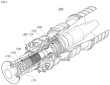
- FIG. 1 is a schematic view illustrating the interior of a gas turbine according to an embodiment of the present disclosure
- FIG. 2 is a schematic view illustrating a combustor of FIG. 1 .
- thermodynamic cycle of a gas turbine 1000 follows a Brayton cycle.
- the Brayton cycle consists of four thermodynamic processes: isentropic compression (adiabatic compression), isobaric combustion, isentropic expansion (adiabatic expansion) and isobaric heat ejection. That is, in the Brayton cycle, atmospheric air is sucked and compressed into high pressure air, mixed gas of fuel and compressed air is combusted at constant pressure to discharge heat energy, heat energy of hot expanded combustion gas is converted into kinetic energy, and exhaust gases containing remaining heat energy is discharged to the outside. That is, gases undergo four thermodynamic processes: compression, heating, expansion, and heat ejection.
- the gas turbine 1000 employing the Brayton cycle includes a compressor 1100, a combustor 1200, and a turbine 1300. Although the following description will be described with reference to FIG. 1 , the present disclosure may be widely applied to other turbine engines similar to the gas turbine 1000 illustrated in FIG. 1 .
- the compressor 1100 of the gas turbine 1000 may suck and compress air.
- the compressor 1100 may serve both to supply the compressed air by compressor blades 1130 to a combustor 1200 and to supply the cooling air to a high temperature region of the gas turbine 1000.
- the sucked air undergoes an adiabatic compression process in the compressor 1100, the air passing through the compressor 1100 has increased pressure and temperature.
- the compressor 1100 is usually designed as a centrifugal compressor or an axial compressor, and the centrifugal compressor is applied to a small-scale gas turbine, whereas a multi-stage axial compressor is applied to a large-scale gas turbine 1000 illustrated in FIG. 1 since the large-scale gas turbine 1000 is required to compress a large amount of air.
- the compressor blades 1130 of the compressor 1100 rotate according to the rotation of the rotor disks to compress the introduced air and move the compressed air to the compressor vanes 1140 on the rear stage. As the air passes through the compressor blades 1130 formed in multiple stages, the air is compressed to a higher pressure.
- the compressor vanes 1140 are mounted inside the housing 1150 in stages.
- the compressor vanes 1140 guide the compressed air moved from the front side compressor blades 1130 toward the rear-side compressor blades 1130.
- at least some of the compressor vanes 1140 may be mounted so as to be rotatable within a predetermined range for adjustment of an air inflow, or the like.
- the compressor 1100 may be driven using a portion of the power output from the turbine 1300. To this end, as illustrated in FIG. 1 , the rotary shaft of the compressor 1100 and the rotary shaft of the turbine 1300 may be directly connected. In the case of the large-scale gas turbine 1000, almost half of the output produced by the turbine 1300 may be consumed to drive the compressor 1100. Accordingly, improving the efficiency of the compressor 1100 has a direct effect on improving the overall efficiency of the gas turbine 1000.
- the turbine 1300 includes a rotor disk 1310 and a plurality of turbine blades and turbine vanes radially disposed on the rotor disk 1310.
- the rotor disk 1310 has a substantially disk shape on which a plurality of grooves is formed.
- the grooves are formed to have curved surfaces, and turbine blades and turbine vanes are inserted into the grooves.
- the turbine vanes are fixed against rotation and guide a flow of combustion gases through the turbine blades.
- the turbine blades are rotated by combustion gases to generate rotational force.
- the combustor 1200 serves to mix the compressed air supplied from an outlet of the compressor 1100 with fuel and combust the mixture at constant pressure to produce hot combustion gases.
- FIG. 2 illustrates an example of the combustor 1200 provided in the gas turbine 1000.
- the combustor 1200 may include a combustor casing 1210, nozzles 1220, and a duct assembly 1240.
- the combustor casing 1210 may have a substantially circular cylindrical shape in which the nozzles 1220 are surrounded.
- the nozzle 1220 is disposed downstream of the compressor 1100 and may be disposed along the annular combustor casing 1210.
- Each nozzle 1220 is provided with at least one nozzle module 1400, through which fuel and air are mixed in an appropriate ratio and injected to achieve a suitable state for combustion.
- the gas turbine 1000 may use a gas fuel, in particular, a fuel containing hydrogen.
- the fuel may include a hydrogen fuel alone or a fuel containing hydrogen and natural gas.
- the duct assembly is provided to connect the nozzles 1220 and the turbine 1300 so that the hot combustion gas flows therethrough to heat the duct assembly, whereas the compressed air flows towards the nozzles 1220 along an outer surface of the duct assembly 1240, thereby properly cooling the heated duct assembly 1240.
- the duct assembly 1240 may include a liner 1241 and a transition piece 1242, and a flow sleeve 1243.
- the duct assembly 1240 has a double structure in which the flow sleeve 1243 surrounds the outside of the liner 1241 and the transition piece 1242, so that compressed air penetrates into an annular space inside the flow sleeve 1243 to cool the liner 1241 and the transition piece 1242.
- the liner 1241 is a tube member connected to the nozzles 1220 of the combustor 1200, wherein an internal space of the liner 1241 defines the combustion chamber 1230.
- a longitudinal one side of the liner 1241 is coupled to the nozzle 1220, and the other side of the liner 1241 is coupled to the transition piece 1242.
- the transition piece 1242 is connected an inlet of the turbine 1300 to guide the hot combustion gas toward the turbine 1300.
- a longitudinal one side of the transition piece 1242 is coupled to the liner 1241, and the other side of the transition piece 1242 is coupled to the turbine 1300.
- the flow sleeve 1243 serves to protect the liner 1241 and the transition piece 1242 while avoiding direct exhaust of hot air to the outside.
- FIG. 3 is a longitudinal cross-sectional schematic view illustrating an overall appearance of a nozzle module according to a first embodiment of the present disclosure
- FIG. 4 is an enlarged schematic view separately illustrating a cooling channel of FIG. 3
- FIG. 5 illustrates a flow rate and temperature distribution at a rear end of a central tube in the nozzle module according to the first embodiment of the present disclosure.
- the combustor nozzle 1220 includes at least one nozzle module 1400, which includes a central tube 1420, a shroud 1430, and a plurality of cooling channels 1450.
- the central tube 1420 may be a tubular member.
- the central tube 1420 may include a sidewall portion 1421 having a predetermined thickness.
- the sidewall portion 1421 has an inner surface 1421a and the outer surface 1421b. The distance between the inner surface 1421a and the outer surface 1421b may be the predetermined thickness.
- the inner surface 1421a forms an air flow path 1423.
- a flange 1410 may be disposed at a front end of the central tube 1420.
- the flange 1410 may be supplied with fuel.
- the air flow path 1423 is formed in an internal space of the central tube 1420 or an internal space defined by the inner surface of the sidewall portion 1421. Air flows in a front-rear direction through the air flow path 1423.
- An opening hole 1424 may be formed at a rear end 1422 of the central tube 1420. Accordingly, air in the air flow path 1423 may flow to the outside through the opening hole 1424.
- An air inlet port 1425 may be formed in the central tube 1420. The air inlet port 1425 is supplied with air. The air inlet port 1425 may be formed to pass through the central tube 1420 to allow the inside and outside of the central tube 1420 to communicate with each other.
- the air inlet port 1425 may be formed at a position slightly spaced apart from the flange 1410 or just behind the flange 1410 in the central tube 1420.
- the air inlet port 1425 may be disposed at a front end of the air flow path 1423. The air introduced through the air inlet port 1425 may flow in the air flow path 1423 of the central tube 1420.
- At least a portion of the central tube 1420 may be inserted into the shroud 1430. According to an embodiment, an entire portion of the central tube 1420 excluding the flange 1410 may be inserted into the shroud 1430. According to an embodiment, the portion of the central tube 1420 where the air inlet port 1425 is formed is not inserted into the shroud 1430 so that the air inlet port 1425 may be disposed in front of the shroud 1430.
- Air inlets 1432 may be formed at a front end of the shroud 1430. Air is introduced through the air inlets 1432. According to an embodiment, a bell mouth 1431 may be formed at the front end of the shroud 1430 to guide air inflow and reduce flow resistance.
- the shroud 1430 may surround the central tube 1420 in a manner as to be spaced apart from the central tube 1420. Accordingly, a space is formed between the shroud 1430 and the central tube 1420. In the space between the shroud 1430 and the central tube 1420, the air introduced from the air inlets 1432 and the separately injected fuel may flow together. Accordingly, the space is referred to as a mixing flow path 1433.
- a fuel port may be formed in the central tube 1420.
- the fuel port is configured to inject fuel into the mixing flow path 1433.
- Fuel is introduced from the flange 1410 side, and the fuel port may communicate with the flange 1410 side.
- a fuel plenum (not depicted) to be filled with fuel may be formed on the sidewall portion 1421 side of the central tube 1420.
- the fuel plenum may extend in the circumferential direction from the sidewall portion 1421 to form an annular space.
- the fuel plenum may communicate with the flange 1410 side, as well as the fuel port. Accordingly, fuel introduced from the flange 1410 may be injected to the outside from the fuel port through the fuel plenum.
- a swirler 1440 may be disposed between the central tube 1420 and the shroud 1430.
- the swirler 1440 may be formed on the inner circumferential surface of the shroud 1430 or the outer circumferential surface of the central tube 1420, or swirlers may be provided separately and coupled to the shroud 1430 and the central tube 1420, respectively.
- the swirler 1440 is configured to swirl air, or air and fuel.
- the swirler 1440 may preferably be disposed near the front end of the shroud 1430 or just behind the bell mouth 1431.
- the fuel port may be disposed on the swirler 1440. If the swirler 1440 is integrally formed with the central tube 1420, the fuel port may be formed through both the central tube 1420 and the swirler 1440. When the fuel port 1428 is disposed in the swirler 1440, the fuel may be injected directly into the air that starts swirling, which improves performance of mixing air and fuel and also minimizes flame backfire due to the fuel port being separated away from the combustion chamber.
- a cooling channel 1450 is formed in the central tube 1420.
- a plurality of cooling channels 1450 may be provided.
- the cooling channel 1450 includes an inlet 1451 and an outlet 1452.
- the inlet 1451 of the cooling channel 1450 may communicate with the air flow path 1423, and the outlet 1452 may communicate with the mixing flow path 1433.
- the cooling channel 1450 may be formed to extend rearward through the sidewall portion 1421 of the central tube 1420.
- the cooling channel 1450 may be formed between the inner surface 1421a and the outer surface 1421b of the sidewall portion 1421. That is, when viewed in a longitudinal cross section, the cooling channel 1450 may be formed to extend left and right such that upper and lower parts thereof are surrounded by the sidewall portion 1421.
- the cooling channel 1450 may be disposed in the sidewall portion 1421 between the inner surface 1421a and the outer surface 1421b so that a portion of the sidewall portion 1421 is disposed between the cooling channel 1450 and the air flow path 1423 while another portion of the sidewall 1421 is disposed between the cooling channel 1450 and the mixing flow path 1433.
- the cooling channel 150 may be formed to extend in an axial direction, which is a direction parallel to the air flow path 1423.
- the plurality of cooling channels 1450 may be disposed to surround the air flow path 1423 with a portion of the sidewall portion 1421 interposed therebetween. According to an embodiment, the plurality of cooling channels 1450 may be disposed in parallel with each other in the sidewall portion 1421.
- the air from the airflow path 1423 flows through the cooling channels 1450.
- the air in the air flow path 1423 is introduced into the cooling channels 1450 and is discharged to the mixing flow path 1433, thereby, the central tube 1420 is being cooled.
- An opening of an inlet 1451 of the cooling channel 1450 may formed and disposed in an inner surface of the sidewall portion 1421.
- the inlet 1451 of the cooling channel 1450 may be obliquely formed with respect to the air flow path 1423.
- the cooling channel 1450 may be formed at a rear end 1422 of the central tube 1420.
- the rear end 1422 of the central tube 1420 is close to the combustion chamber, so the rear end may be exposed to high temperature. Near the rear end 1422 of the central tube 1420, a flame of the combustion chamber may be backfired and attached thereto. Even though this is not the case, the rear end may be exposed to relatively high temperature because the rear end is close to the combustion chamber.
- the cooling channel 1450 may preferably be formed at the rear end 1422 of the central tube 1420.
- a first annular flow path 1453 may be formed in the sidewall portion 1421.
- the first annular flow path 1453 may be formed in an annular shape by extending in the circumferential direction of the central tube 1420 in the sidewall portion 1421. That is, the first annular flow path 1453 may be arranged in the sidewall portion 1421 such that a part of the sidewall portion 1421 is disposed between the first annular flow path 1453 and the air flow path 1423, while another part of the sidewall portion 1421 is disposed between the first annular flow path 1453 and the mixing flow path 1433.
- the first annular flow path 1453 may connect and communicate with all of the cooling channels 1450.
- At least a part of the air flowing in the plurality of cooling channels 1450 may be introduced into and flows through the first annular flow path 1453.
- the first annular flow path 1453 may be formed between the inlet 1451 and the outlet 1452 of the cooling channel 1450.
- the air introduced into the inlet 1451 flows into the first annular flow path 1453, then at least a part of the air may circulate in the circumferential direction through the first annular flow path in the sidewall portion 1421, and then is discharged to one of outlets 1452 of cooling channels 150.
- an airflow may be uniformly formed in the plurality of cooling channels 1450.
- an air swirler 1460 may be disposed in the air flow path 1423.
- the air swirler 1460 is configured to swirl an airflow in the air flow path 1423 of the central tube 1420.
- the air swirler 1460 may include a plurality of turning wings (not shown). Air passing through the air swirler 1460 may be swirled, and the swirled airflow may be in close contact with the inner circumferential surface of the sidewall portion 1421 of the central tube 1420 by centrifugal force. Accordingly, the cooling performance of the central tube 1420 may be further improved.
- the air swirler 1460 may be disposed to be spaced apart from the rear end 1422 of the central tube 1420. If the air swirler 1460 is located at a distal portion or at the rearward terminal of the rear end 1422 of the central tube 1420, the cooling performance may be reduced because there is little swirled airflow in the central tube 1420. Accordingly, the position of the air swirler 1460 is preferably arranged spaced apart from the rear end 1422 of the central tube 1420.
- the air swirler 1460 is positioned too far apart from the rear end 1422 of the central tube 1420, the cooling performance by the air swirler 1460 may be reduced.
- the swirled air may gradually increase straightness as the flow progresses, and accordingly, if the air swirler 1460 is positioned too far apart, the swirled airflow may hardly touch the rear end 1422 of the central tube 1420, which reduces the cooling performance.
- the air swirler 1460 is preferably disposed near the rear end 1422 of the central tube 1420 while being spaced apart from the rear end 1422 of the central tube 1420.
- the air swirler 1460 may preferably be disposed behind the inlet 1451 of the cooling channel 1450. According to an embodiment, the air swirler 1460 may be disposed between the inlet 1451 and the rear end 1422
- FIG. 6 is an enlarged schematic view illustrating a cooling channel of a nozzle module according to a second embodiment of the present disclosure.
- a combustor nozzle 1220 according to a second embodiment of the present disclosure will be described in detail with referenced to FIG. 6 .
- the combustor nozzle 1220 according to the second embodiment of the present disclosure is the same as the combustor nozzle 1220 according to the first embodiment of the present disclosure, except for the air swirler 1460 and a turbulence-forming member 1470, so a redundant description thereof will be omitted.
- the air swirler 1460 may be replaced by a turbulence-forming member 1470.
- the turbulence-forming member 1470 is configured to form a turbulence in the airflow in the air flow path 1423 of the central tube 1420.
- the turbulence-forming member 1470 may be formed in the form of a protrusion or protrusions on the inner circumferential surface of the sidewall portion 1421.
- the turbulence-forming member 1470 may be disposed to be spaced apart from the rear end 1422 of the central tube 1420. If the turbulence-forming member 1470 is located at a distal portion or at the rearend terminal of the rear end 1422 of the central tube 1420, the cooling performance may be reduced because the turbulent airflow is hardly formed inside the central tube 1420. Accordingly, it is preferable that the position of the turbulence-forming member 1470 is arranged spaced apart from the rear end 1422 of the central tube 1420.
- the cooling performance by the turbulence-forming member 1470 may rather decrease.
- the turbulent airflow may gradually change to a laminar flow as the flow progresses. Accordingly, if the turbulence-forming member 1470 is positioned too far apart from the rear end 1422 of the central tube 1420, a laminar airflow flows in the rear end 1422 of the central tube 1420, which reduces cooling performance. Accordingly, the turbulence-forming member 1470 is preferably disposed near the rear end 1422 of the central tube 1420 while being spared apart from the rear end 1422 of the central tube 1420.
- the turbulence-forming member 1470 may preferably be disposed behind the inlet 1451 of the cooling channel 1450. According to an embodiment, the turbulence-forming member 1470 may be disposed between the inlet 1451 and the rear end 1422.
- the air flow path 1423 is formed such that the internal width of the air flow path 1423 is decreased between the inlet of the 1451 and the turbulence-forming member 1470 in a direction toward the rear end 1422.
- FIG. 7 is an enlarged schematic view illustrating a cooling channel of a nozzle module according to a third embodiment of the present disclosure.
- a combustor nozzle 1220 according to a third embodiment of the present disclosure will be described in detail with reference to FIG. 7 .
- the combustor nozzle 1220 according to the third embodiment of the present disclosure is the same as the combustor nozzle 1220 according to the first embodiment of the present disclosure, except for the cooling channel 1450, so a redundant description thereof will be omitted.
- a plurality of cooling channels 1450 may be formed in a spiral shape.
- the plurality of cooling channels 1450 may be spirally formed from the inlet 1451 toward the outlet 1452 in the sidewall portion 1421 of the central tube 1420. That is, the plurality of cooling channels 1450 may be formed in a multi-helical shape.
- the cooling channel 1450 may be formed to extend along the circumferential and axial directions in the sidewall portion 1421.
- the cooling channel 1450 of the spiral structure since air used for cooling flows more evenly in the sidewall portion 1421, there is an advantage of further increasing the cooling performance of the central tube 1420.
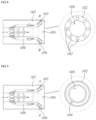
- FIG. 8 is an enlarged schematic view illustrating a cooling channel of a nozzle module according to a fourth embodiment of the present disclosure
- FIG. 9 illustrates a modified example of FIG. 8
- the cross sectional view of the cooling channel of a nozzle in a direction B-B' is depicted on the right.
- the cross sectional view of the cooling channel of a nozzle in a direction A-A' is depicted on the right.
- a combustor nozzle 1220 according to a fourth embodiment of the present disclosure will be described in detail with reference to FIGS. 8 and 9 .
- the combustor nozzle 1220 according to the fourth embodiment of the present disclosure is the same as the combustor nozzle 1220 according to the first embodiment of the present disclosure, except for an extension part 1426, so a redundant description thereof will be omitted.
- the combustor nozzle 1220 further includes an extension part 1426.
- the extension part 1426 is formed in the opening hole 1424 at the rear end 1422 of the central tube 1420.
- the expansion part 1426 is a portion in which a flow cross-sectional area increases toward the rear side or from the upstream to the downstream.
- the expansion part 1426 is formed in the opening hole 1424 located at the rear end of the central tube 1420, the air may spread out in the radial direction while being discharged from the central tube 1420, so the cooling performance of the central tube 1420 may be further improved.
- the outlet 1452 of the cooling channel 1450 may be formed to be inclined along the axial and radial directions of the central tube 1420 around the extension part 1426. Specifically, the outlet 1452 of the cooling channel 1450 may be formed to extend in parallel with the inner surface of the extension part 1426 to correspond to the shape of the extended flow path of the extension part 1426. In this case, since the air discharged from the cooling channel 1450 spread out not only in the axial direction but also in the radial direction, the cooling performance may be further improved.
- a second annular flow path 1454 may be formed around the extension part 1426.
- the second annular flow path 1454 is an annular flow path along the circumferential direction in the sidewall portion 1421 of the central tube 1420.
- the second annular flow path 1454 may have a cross-section corresponding to the cross-section of the extension part 1426.
- a cross section of an annular shape of the second annular flow path 1454 is concentric with a cross section of an annular shape of the extension part 1426. Accordingly, the portion of the sidewall portion 1421 where the second annular flow path 1454 is formed may have a double wall structure.
- All outlets 1452 of the plurality of cooling channels 1450 may communicate with the second annular flow path 1454. For this reason, air discharged from each of the outlets 1452 of the cooling channel 1450 may flow into and circulate along the second annular flow path 1454, and then discharged to the outside from the rear end 1422 of the central tube 1420. As the second annular flow path 1454 is formed, the airflow discharged from the cooling channel 1450 may be formed more uniformly, which provides an advantage that higher cooling performance may be expected in the central tube 1420.
Landscapes
- Engineering & Computer Science (AREA)
- Chemical & Material Sciences (AREA)
- Combustion & Propulsion (AREA)
- Mechanical Engineering (AREA)
- General Engineering & Computer Science (AREA)
- Turbine Rotor Nozzle Sealing (AREA)
- Gas Burners (AREA)
Abstract
Description
- The present application claims priority to
Korean Patent Application No. 10-2022-0007493, filed on January 18, 2022 - The present disclosure relates to a combustor nozzle and, more particularly, to a combustor nozzle including cooling channels, a combustor, and a gas turbine including the same.
- A gas turbine is a combustion engine in which a mixture of air compressed by a compressor and fuel is combusted to produce a high temperature gas, which drives a turbine. The gas turbine is used to drive electric generators, aircraft, ships, trains, or the like.
- The gas turbine generally includes a compressor, a combustor, and a turbine. The compressor serves to intake external air, compress the air, and transfer the compressed air to the combustor. The compressed air compressed by the compressor has a high temperature and a high pressure. The combustor serves to mix compressed air from the compressor and fuel and combust the mixture of compressed air and fuel to produce combustion gases, which are discharged to the gas turbine. The combustion gases drive turbine blades in the turbine to produce power. The power generated through the above processes is applied to a variety of fields such as generation of electricity, driving of mechanical units, etc.
- Fuel is injected through nozzles disposed in respective combustors, wherein the fuel includes gaseous fuel and liquid fuel. In recent years, in order to suppress the emission of carbon dioxide, use of hydrogen fuel or a fuel containing hydrogen is recommended.
- However, since hydrogen has a high combustion rate, when such fuels are burned with a gas turbine combustor, the flame formed in the gas turbine combustor approaches and heats the structure of the gas turbine combustor, thereby degrading the reliability of the gas turbine combustor.
- The foregoing is intended merely to aid in the understanding of the background of the present disclosure, and is not intended to mean that the present disclosure falls within the purview of the related art that is already known to those skilled in the art.
- Accordingly, the present disclosure has been made keeping in mind the above problems occurring in the related art, and an objective of the present disclosure is to provide a combustor nozzle capable of effectively cooling a central tube and minimizing flame attachment to the central tube and flame backfire, a combustor, and a gas turbine including the same.
- In an aspect of the present disclosure, there is provided a combustor nozzle including: a central tube; a shroud; and a plurality of cooling channels. The central tube has an internal air flow path, through which air flows from a front-to-rear direction, and an opening hole at a rear end thereof. At least a part of the central tube is inserted into the shroud, a mixing flow path is formed between the shroud and the central tube so that air and injected fuel flow therethrough, and an air inlet is formed at a front end of the shroud. The cooling channel extends rearward from an inlet communicating with the air flow path to an outlet communicating with the mixing flow path while passing through a sidewall portion of the central tube.
- In an embodiment, the outlet of the cooling channel may be formed at the rear end of the central tube.
- In an embodiment, a first annular flow path may be formed in the sidewall portion of the central tube to allow the plurality of cooling channels to communicate with each other.
- In an embodiment, the first annular flow path may be disposed between the inlet and the outlet of the cooling channel.
- In an embodiment, an air swirler may be disposed in the air flow path for turning an airflow.
- In an embodiment, the air swirler may be disposed to be spaced apart from the rear end of the central tube.
- In an embodiment, the air swirler may be disposed behind the inlet of the cooling channel.
- In an embodiment, a turbulence-forming member may be disposed in the air flow path for forming a turbulence in the airflow.
- In an embodiment, the turbulence-forming member may be disposed to be spaced apart from the rear end of the central tube.
- In an embodiment, the turbulence-forming member may be disposed behind the inlet of the cooling channel.
- In an embodiment, the plurality of cooling channels may be disposed in parallel in the sidewall portion of the central tube.
- In an embodiment, the plurality of cooling channels may be spirally disposed in the sidewall portion of the central tube.
- In an embodiment, the opening hole of the central tube may be provided with an extension part having a flow cross-sectional area increasing toward a rear end thereof.
- In an embodiment, the outlet of the cooling channel may be formed at the rear end of the central tube so as to be inclined in axial and radial directions around the extension part.
- In an embodiment, a second annular flow path may be formed around the extension part and the rear end of the central tube so that one end thereof communicates with all of the outlets of the cooling channels and the other end thereof communicates with the mixing flow path.
- A combustor according to an embodiment of the present disclosure includes a combustor nozzle and a duct assembly. The duct assembly is coupled to one side of the nozzle. In the duct assembly, fuel and air are combusted, and the combustion gas is delivered to a turbine. The nozzle includes a central tube, a shroud, and a plurality of cooling channels. The central tube has an internal air flow path, through which air flows from a front-to-rear direction, and an opening hole at a rear end thereof. At least a part of the central tube is inserted into the shroud, a mixing flow path is formed between the shroud and the central tube so that air and injected fuel flow therethrough, and an air inlet is formed at a front end of the shroud. The cooling channel extends rearward from an inlet communicating with the air flow path to an outlet communicating with the mixing flow path while passing through a sidewall portion of the central tube.
- In an embodiment, a turbulence-forming member may be disposed in the air flow path for forming a turbulence in the airflow.
- In an embodiment, the plurality of cooling channels may be spirally disposed in the sidewall portion of the central tube.
- In an embodiment, the opening hole of the central tube may be provided with an extension part having a flow cross-sectional area increasing toward a rear end thereof.
- In another aspect of the present disclosure, there is provided a gas turbine including a compressor, a combustor, and a turbine. The compressor compresses air introduced from the outside. The combustor mixes the compressed air compressed in the compressor and fuel and burns an air-fuel mixture. The turbine includes a plurality of turbine blades to be rotated by combustion gases combusted in the combustor. The combustor includes a combustor nozzle and a duct assembly. The duct assembly is coupled to one side of the nozzle. In the duct assembly, fuel and air are combusted, and the combustion gas is delivered to a turbine. The nozzle includes a central tube, a shroud, and a plurality of cooling channels. The central tube has an internal air flow path, through which air flows from a front-to-rear direction, and an opening hole at a rear end thereof. At least a part of the central tube is inserted into the shroud, a mixing flow path is formed between the shroud and the central tube so that air and injected fuel flow therethrough, and an air inlet is formed at a front end of the shroud. The cooling channel extends rearward from an inlet communicating with the air flow path to an outlet communicating with the mixing flow path while passing through a sidewall portion of the central tube.
- According to the combustor nozzle, the combustor, and the gas turbine including the same, the cooling channels are formed in central tubes so that the central tube can be effectively cooled, and flame attachment to the central tube and flame backfire can be minimized.
-
-
FIG. 1 is a view illustrating the interior of a gas turbine according to a first embodiment of the present disclosure; -
FIG. 2 is a view illustrating a combustor ofFIG. 1 ; -
FIG. 3 is a longitudinal cross-sectional view illustrating the overall appearance of a nozzle module according to a first embodiment of the present disclosure; -
FIG. 4 is an enlarged view separately illustrating a cooling channel ofFIG. 3 ; -
FIG. 5 illustrates a flow rate and temperature distribution at a rear end of a central tube in the nozzle module according to the first embodiment of the present disclosure; -
FIG. 6 is an enlarged view illustrating a cooling channel of a nozzle module according to a second embodiment of the present disclosure; -
FIG. 7 is an enlarged view illustrating a cooling channel of a nozzle module according to a third embodiment of the present disclosure; -
FIG. 8 is an enlarged view illustrating a cooling channel of a nozzle module according to a fourth embodiment of the present disclosure; and -
FIG. 9 illustrates a modified example ofFIG. 8 . - Hereinafter, exemplary embodiments of the present disclosure will be described in detail with reference to the accompanying drawings. However, it should be noted that the present disclosure is not limited thereto, but may include all of modifications, equivalents or substitutions within the spirit and scope of the present disclosure.
- Terms used herein are used to merely describe specific embodiments, and are not intended to limit the present disclosure. As used herein, an element expressed as a singular form includes a plurality of elements, unless the context clearly indicates otherwise. Further, it will be understood that the terms "including" or "comprising" specifies the presence of stated features, numbers, steps, operations, elements, parts, or combinations thereof, but does not preclude the presence or addition of one or more other features, numbers, steps, operations, elements, parts, or combinations thereof.
- Hereinafter, preferred embodiments of the present disclosure will be described in detail with reference to the accompanying drawings. It is noted that like elements are denoted in the drawings by like reference symbols as whenever possible. Further, the detailed description of known functions and configurations that may obscure the gist of the present disclosure will be omitted. For the same reason, some of the elements in the drawings are exaggerated, omitted, or schematically illustrated.
- Hereinafter, a combustor nozzle, a combustor, and a gas turbine including the same according to the present disclosure will be described.
-
FIG. 1 is a schematic view illustrating the interior of a gas turbine according to an embodiment of the present disclosure, andFIG. 2 is a schematic view illustrating a combustor ofFIG. 1 . - The gas turbine will now be described with reference to
FIGS. 1 and2 . - An ideal thermodynamic cycle of a
gas turbine 1000 according to the present embodiment follows a Brayton cycle. The Brayton cycle consists of four thermodynamic processes: isentropic compression (adiabatic compression), isobaric combustion, isentropic expansion (adiabatic expansion) and isobaric heat ejection. That is, in the Brayton cycle, atmospheric air is sucked and compressed into high pressure air, mixed gas of fuel and compressed air is combusted at constant pressure to discharge heat energy, heat energy of hot expanded combustion gas is converted into kinetic energy, and exhaust gases containing remaining heat energy is discharged to the outside. That is, gases undergo four thermodynamic processes: compression, heating, expansion, and heat ejection. - As illustrated in
FIG. 1 , thegas turbine 1000 employing the Brayton cycle includes acompressor 1100, acombustor 1200, and aturbine 1300. Although the following description will be described with reference toFIG. 1 , the present disclosure may be widely applied to other turbine engines similar to thegas turbine 1000 illustrated inFIG. 1 . - Referring to
FIG. 1 , thecompressor 1100 of thegas turbine 1000 may suck and compress air. Thecompressor 1100 may serve both to supply the compressed air bycompressor blades 1130 to acombustor 1200 and to supply the cooling air to a high temperature region of thegas turbine 1000. Here, since the sucked air undergoes an adiabatic compression process in thecompressor 1100, the air passing through thecompressor 1100 has increased pressure and temperature. - The
compressor 1100 is usually designed as a centrifugal compressor or an axial compressor, and the centrifugal compressor is applied to a small-scale gas turbine, whereas a multi-stage axial compressor is applied to a large-scale gas turbine 1000 illustrated inFIG. 1 since the large-scale gas turbine 1000 is required to compress a large amount of air. In this case, in the multi-stage axial compressor, thecompressor blades 1130 of thecompressor 1100 rotate according to the rotation of the rotor disks to compress the introduced air and move the compressed air to thecompressor vanes 1140 on the rear stage. As the air passes through thecompressor blades 1130 formed in multiple stages, the air is compressed to a higher pressure. - The
compressor vanes 1140 are mounted inside thehousing 1150 in stages. Thecompressor vanes 1140 guide the compressed air moved from the frontside compressor blades 1130 toward the rear-side compressor blades 1130. In one embodiment, at least some of thecompressor vanes 1140 may be mounted so as to be rotatable within a predetermined range for adjustment of an air inflow, or the like. - The
compressor 1100 may be driven using a portion of the power output from theturbine 1300. To this end, as illustrated inFIG. 1 , the rotary shaft of thecompressor 1100 and the rotary shaft of theturbine 1300 may be directly connected. In the case of the large-scale gas turbine 1000, almost half of the output produced by theturbine 1300 may be consumed to drive thecompressor 1100. Accordingly, improving the efficiency of thecompressor 1100 has a direct effect on improving the overall efficiency of thegas turbine 1000. - The
turbine 1300 includes arotor disk 1310 and a plurality of turbine blades and turbine vanes radially disposed on therotor disk 1310. Therotor disk 1310 has a substantially disk shape on which a plurality of grooves is formed. The grooves are formed to have curved surfaces, and turbine blades and turbine vanes are inserted into the grooves. The turbine vanes are fixed against rotation and guide a flow of combustion gases through the turbine blades. The turbine blades are rotated by combustion gases to generate rotational force. - On the other hand, the
combustor 1200 serves to mix the compressed air supplied from an outlet of thecompressor 1100 with fuel and combust the mixture at constant pressure to produce hot combustion gases.FIG. 2 illustrates an example of thecombustor 1200 provided in thegas turbine 1000. Thecombustor 1200 may include acombustor casing 1210,nozzles 1220, and aduct assembly 1240. - The
combustor casing 1210 may have a substantially circular cylindrical shape in which thenozzles 1220 are surrounded. Thenozzle 1220 is disposed downstream of thecompressor 1100 and may be disposed along theannular combustor casing 1210. Eachnozzle 1220 is provided with at least onenozzle module 1400, through which fuel and air are mixed in an appropriate ratio and injected to achieve a suitable state for combustion. - The
gas turbine 1000 may use a gas fuel, in particular, a fuel containing hydrogen. The fuel may include a hydrogen fuel alone or a fuel containing hydrogen and natural gas. - The duct assembly is provided to connect the
nozzles 1220 and theturbine 1300 so that the hot combustion gas flows therethrough to heat the duct assembly, whereas the compressed air flows towards thenozzles 1220 along an outer surface of theduct assembly 1240, thereby properly cooling theheated duct assembly 1240. - The
duct assembly 1240 may include aliner 1241 and atransition piece 1242, and aflow sleeve 1243. Theduct assembly 1240 has a double structure in which theflow sleeve 1243 surrounds the outside of theliner 1241 and thetransition piece 1242, so that compressed air penetrates into an annular space inside theflow sleeve 1243 to cool theliner 1241 and thetransition piece 1242. - The
liner 1241 is a tube member connected to thenozzles 1220 of thecombustor 1200, wherein an internal space of theliner 1241 defines thecombustion chamber 1230. A longitudinal one side of theliner 1241 is coupled to thenozzle 1220, and the other side of theliner 1241 is coupled to thetransition piece 1242. - The
transition piece 1242 is connected an inlet of theturbine 1300 to guide the hot combustion gas toward theturbine 1300. A longitudinal one side of thetransition piece 1242 is coupled to theliner 1241, and the other side of thetransition piece 1242 is coupled to theturbine 1300. Theflow sleeve 1243 serves to protect theliner 1241 and thetransition piece 1242 while avoiding direct exhaust of hot air to the outside. -
FIG. 3 is a longitudinal cross-sectional schematic view illustrating an overall appearance of a nozzle module according to a first embodiment of the present disclosure,FIG. 4 is an enlarged schematic view separately illustrating a cooling channel ofFIG. 3 , andFIG. 5 illustrates a flow rate and temperature distribution at a rear end of a central tube in the nozzle module according to the first embodiment of the present disclosure. - Hereinafter, the
combustor nozzle 1220 according to the first embodiment of the present disclosure will be described in detail with reference toFIGS. 3 to 5 . Thecombustor nozzle 1220 includes at least onenozzle module 1400, which includes acentral tube 1420, ashroud 1430, and a plurality ofcooling channels 1450. - The
central tube 1420 may be a tubular member. Thecentral tube 1420 may include asidewall portion 1421 having a predetermined thickness. Thesidewall portion 1421 has aninner surface 1421a and theouter surface 1421b. The distance between theinner surface 1421a and theouter surface 1421b may be the predetermined thickness. Theinner surface 1421a forms anair flow path 1423. Aflange 1410 may be disposed at a front end of thecentral tube 1420. Theflange 1410 may be supplied with fuel. Theair flow path 1423 is formed in an internal space of thecentral tube 1420 or an internal space defined by the inner surface of thesidewall portion 1421. Air flows in a front-rear direction through theair flow path 1423. Anopening hole 1424 may be formed at arear end 1422 of thecentral tube 1420. Accordingly, air in theair flow path 1423 may flow to the outside through theopening hole 1424. Anair inlet port 1425 may be formed in thecentral tube 1420. Theair inlet port 1425 is supplied with air. Theair inlet port 1425 may be formed to pass through thecentral tube 1420 to allow the inside and outside of thecentral tube 1420 to communicate with each other. Theair inlet port 1425 may be formed at a position slightly spaced apart from theflange 1410 or just behind theflange 1410 in thecentral tube 1420. Theair inlet port 1425 may be disposed at a front end of theair flow path 1423. The air introduced through theair inlet port 1425 may flow in theair flow path 1423 of thecentral tube 1420. - At least a portion of the
central tube 1420 may be inserted into theshroud 1430. According to an embodiment, an entire portion of thecentral tube 1420 excluding theflange 1410 may be inserted into theshroud 1430. According to an embodiment, the portion of thecentral tube 1420 where theair inlet port 1425 is formed is not inserted into theshroud 1430 so that theair inlet port 1425 may be disposed in front of theshroud 1430. -
Air inlets 1432 may be formed at a front end of theshroud 1430. Air is introduced through theair inlets 1432. According to an embodiment, abell mouth 1431 may be formed at the front end of theshroud 1430 to guide air inflow and reduce flow resistance. Theshroud 1430 may surround thecentral tube 1420 in a manner as to be spaced apart from thecentral tube 1420. Accordingly, a space is formed between theshroud 1430 and thecentral tube 1420. In the space between theshroud 1430 and thecentral tube 1420, the air introduced from theair inlets 1432 and the separately injected fuel may flow together. Accordingly, the space is referred to as a mixingflow path 1433. - According to an embodiment, a fuel port (not depicted) may be formed in the
central tube 1420. The fuel port is configured to inject fuel into the mixingflow path 1433. Fuel is introduced from theflange 1410 side, and the fuel port may communicate with theflange 1410 side. A fuel plenum (not depicted) to be filled with fuel may be formed on thesidewall portion 1421 side of thecentral tube 1420. The fuel plenum may extend in the circumferential direction from thesidewall portion 1421 to form an annular space. The fuel plenum may communicate with theflange 1410 side, as well as the fuel port. Accordingly, fuel introduced from theflange 1410 may be injected to the outside from the fuel port through the fuel plenum. - According to an embodiment, a
swirler 1440 may be disposed between thecentral tube 1420 and theshroud 1430. Theswirler 1440 may be formed on the inner circumferential surface of theshroud 1430 or the outer circumferential surface of thecentral tube 1420, or swirlers may be provided separately and coupled to theshroud 1430 and thecentral tube 1420, respectively. Theswirler 1440 is configured to swirl air, or air and fuel. Theswirler 1440 may preferably be disposed near the front end of theshroud 1430 or just behind thebell mouth 1431. In addition, the fuel port may be disposed on theswirler 1440. If theswirler 1440 is integrally formed with thecentral tube 1420, the fuel port may be formed through both thecentral tube 1420 and theswirler 1440. When the fuel port 1428 is disposed in theswirler 1440, the fuel may be injected directly into the air that starts swirling, which improves performance of mixing air and fuel and also minimizes flame backfire due to the fuel port being separated away from the combustion chamber. - A
cooling channel 1450 is formed in thecentral tube 1420. According to an embodiment, a plurality ofcooling channels 1450 may be provided. Thecooling channel 1450 includes aninlet 1451 and anoutlet 1452. Theinlet 1451 of thecooling channel 1450 may communicate with theair flow path 1423, and theoutlet 1452 may communicate with the mixingflow path 1433. According to an embodiment, thecooling channel 1450 may be formed to extend rearward through thesidewall portion 1421 of thecentral tube 1420. Thecooling channel 1450 may be formed between theinner surface 1421a and theouter surface 1421b of thesidewall portion 1421. That is, when viewed in a longitudinal cross section, thecooling channel 1450 may be formed to extend left and right such that upper and lower parts thereof are surrounded by thesidewall portion 1421. Thecooling channel 1450 may be disposed in thesidewall portion 1421 between theinner surface 1421a and theouter surface 1421b so that a portion of thesidewall portion 1421 is disposed between the coolingchannel 1450 and theair flow path 1423 while another portion of thesidewall 1421 is disposed between the coolingchannel 1450 and the mixingflow path 1433. The cooling channel 150 may be formed to extend in an axial direction, which is a direction parallel to theair flow path 1423. The plurality ofcooling channels 1450 may be disposed to surround theair flow path 1423 with a portion of thesidewall portion 1421 interposed therebetween. According to an embodiment, the plurality ofcooling channels 1450 may be disposed in parallel with each other in thesidewall portion 1421. The air from theairflow path 1423 flows through thecooling channels 1450. The air in theair flow path 1423 is introduced into thecooling channels 1450 and is discharged to themixing flow path 1433, thereby, thecentral tube 1420 is being cooled. An opening of aninlet 1451 of thecooling channel 1450 may formed and disposed in an inner surface of thesidewall portion 1421. Theinlet 1451 of thecooling channel 1450 may be obliquely formed with respect to theair flow path 1423. - According to an embodiment, the
cooling channel 1450 may be formed at arear end 1422 of thecentral tube 1420. Therear end 1422 of thecentral tube 1420 is close to the combustion chamber, so the rear end may be exposed to high temperature. Near therear end 1422 of thecentral tube 1420, a flame of the combustion chamber may be backfired and attached thereto. Even though this is not the case, the rear end may be exposed to relatively high temperature because the rear end is close to the combustion chamber. Accordingly, thecooling channel 1450 may preferably be formed at therear end 1422 of thecentral tube 1420. - According to an embodiment, a first
annular flow path 1453 may be formed in thesidewall portion 1421. The firstannular flow path 1453 may be formed in an annular shape by extending in the circumferential direction of thecentral tube 1420 in thesidewall portion 1421. That is, the firstannular flow path 1453 may be arranged in thesidewall portion 1421 such that a part of thesidewall portion 1421 is disposed between the firstannular flow path 1453 and theair flow path 1423, while another part of thesidewall portion 1421 is disposed between the firstannular flow path 1453 and the mixingflow path 1433. The firstannular flow path 1453 may connect and communicate with all of thecooling channels 1450. According to an embodiment, at least a part of the air flowing in the plurality ofcooling channels 1450 may be introduced into and flows through the firstannular flow path 1453. The firstannular flow path 1453 may be formed between theinlet 1451 and theoutlet 1452 of thecooling channel 1450. In this case, the air introduced into theinlet 1451 flows into the firstannular flow path 1453, then at least a part of the air may circulate in the circumferential direction through the first annular flow path in thesidewall portion 1421, and then is discharged to one ofoutlets 1452 of cooling channels 150. As the firstannular flow path 1453 is formed in thesidewall portion 1421, an airflow may be uniformly formed in the plurality ofcooling channels 1450. - According to an embodiment, an
air swirler 1460 may be disposed in theair flow path 1423. Theair swirler 1460 is configured to swirl an airflow in theair flow path 1423 of thecentral tube 1420. Theair swirler 1460 may include a plurality of turning wings (not shown). Air passing through theair swirler 1460 may be swirled, and the swirled airflow may be in close contact with the inner circumferential surface of thesidewall portion 1421 of thecentral tube 1420 by centrifugal force. Accordingly, the cooling performance of thecentral tube 1420 may be further improved. - According to an embodiment, the
air swirler 1460 may be disposed to be spaced apart from therear end 1422 of thecentral tube 1420. If theair swirler 1460 is located at a distal portion or at the rearward terminal of therear end 1422 of thecentral tube 1420, the cooling performance may be reduced because there is little swirled airflow in thecentral tube 1420. Accordingly, the position of theair swirler 1460 is preferably arranged spaced apart from therear end 1422 of thecentral tube 1420. - However, if the
air swirler 1460 is positioned too far apart from therear end 1422 of thecentral tube 1420, the cooling performance by theair swirler 1460 may be reduced. The swirled air may gradually increase straightness as the flow progresses, and accordingly, if theair swirler 1460 is positioned too far apart, the swirled airflow may hardly touch therear end 1422 of thecentral tube 1420, which reduces the cooling performance. Accordingly, theair swirler 1460 is preferably disposed near therear end 1422 of thecentral tube 1420 while being spaced apart from therear end 1422 of thecentral tube 1420. - Also, if the
air swirler 1460 is disposed in front of theinlet 1451 of thecooling channel 1450, since the air may not flow smoothly into thecooling channel 1450, according to an embodiment, theair swirler 1460 may preferably be disposed behind theinlet 1451 of thecooling channel 1450. According to an embodiment, theair swirler 1460 may be disposed between theinlet 1451 and therear end 1422 -
FIG. 6 is an enlarged schematic view illustrating a cooling channel of a nozzle module according to a second embodiment of the present disclosure. - Hereinafter, a
combustor nozzle 1220 according to a second embodiment of the present disclosure will be described in detail with referenced toFIG. 6 . Thecombustor nozzle 1220 according to the second embodiment of the present disclosure is the same as thecombustor nozzle 1220 according to the first embodiment of the present disclosure, except for theair swirler 1460 and a turbulence-formingmember 1470, so a redundant description thereof will be omitted. - In the
combustor nozzle 1220 according to the second embodiment, theair swirler 1460 may be replaced by a turbulence-formingmember 1470. The turbulence-formingmember 1470 is configured to form a turbulence in the airflow in theair flow path 1423 of thecentral tube 1420. The turbulence-formingmember 1470 may be formed in the form of a protrusion or protrusions on the inner circumferential surface of thesidewall portion 1421. When the air passes through the turbulence-formingmember 1470, a turbulence is formed in the airflow, and thus, a flow rate of air supplied to the inner circumferential surface of thesidewall portion 1421 may increase. Accordingly, the cooling performance of thecentral tube 1420 may be further improved. - According to an embodiment, the turbulence-forming
member 1470 may be disposed to be spaced apart from therear end 1422 of thecentral tube 1420. If the turbulence-formingmember 1470 is located at a distal portion or at the rearend terminal of therear end 1422 of thecentral tube 1420, the cooling performance may be reduced because the turbulent airflow is hardly formed inside thecentral tube 1420. Accordingly, it is preferable that the position of the turbulence-formingmember 1470 is arranged spaced apart from therear end 1422 of thecentral tube 1420. - However, if the turbulence-forming
member 1470 is too far apart from therear end 1422 of thecentral tube 1420, the cooling performance by the turbulence-formingmember 1470 may rather decrease. The turbulent airflow may gradually change to a laminar flow as the flow progresses. Accordingly, if the turbulence-formingmember 1470 is positioned too far apart from therear end 1422 of thecentral tube 1420, a laminar airflow flows in therear end 1422 of thecentral tube 1420, which reduces cooling performance. Accordingly, the turbulence-formingmember 1470 is preferably disposed near therear end 1422 of thecentral tube 1420 while being spared apart from therear end 1422 of thecentral tube 1420. - Also, if the turbulence-forming
member 1470 is disposed in front of theinlet 1451 of thecooling channel 1450, since the air may not flow smoothly into thecooling channel 1450, according to an embodiment the turbulence-formingmember 1470 may preferably be disposed behind theinlet 1451 of thecooling channel 1450. According to an embodiment, the turbulence-formingmember 1470 may be disposed between theinlet 1451 and therear end 1422. - According to embodiment, the
air flow path 1423 is formed such that the internal width of theair flow path 1423 is decreased between the inlet of the 1451 and the turbulence-formingmember 1470 in a direction toward therear end 1422. -
FIG. 7 is an enlarged schematic view illustrating a cooling channel of a nozzle module according to a third embodiment of the present disclosure. - Hereinafter, a
combustor nozzle 1220 according to a third embodiment of the present disclosure will be described in detail with reference toFIG. 7 . Thecombustor nozzle 1220 according to the third embodiment of the present disclosure is the same as thecombustor nozzle 1220 according to the first embodiment of the present disclosure, except for thecooling channel 1450, so a redundant description thereof will be omitted. - In the
combustor nozzle 1220 according to the third embodiment of the present disclosure, a plurality ofcooling channels 1450 may be formed in a spiral shape. The plurality ofcooling channels 1450 may be spirally formed from theinlet 1451 toward theoutlet 1452 in thesidewall portion 1421 of thecentral tube 1420. That is, the plurality ofcooling channels 1450 may be formed in a multi-helical shape. - In this case, the
cooling channel 1450 may be formed to extend along the circumferential and axial directions in thesidewall portion 1421. In thecooling channel 1450 of the spiral structure, since air used for cooling flows more evenly in thesidewall portion 1421, there is an advantage of further increasing the cooling performance of thecentral tube 1420. -
FIG. 8 is an enlarged schematic view illustrating a cooling channel of a nozzle module according to a fourth embodiment of the present disclosure, andFIG. 9 illustrates a modified example ofFIG. 8 . InFIG. 8 , the cross sectional view of the cooling channel of a nozzle in a direction B-B' is depicted on the right. InFIG. 9 , the cross sectional view of the cooling channel of a nozzle in a direction A-A' is depicted on the right. - Hereinafter, a
combustor nozzle 1220 according to a fourth embodiment of the present disclosure will be described in detail with reference toFIGS. 8 and 9 . Thecombustor nozzle 1220 according to the fourth embodiment of the present disclosure is the same as thecombustor nozzle 1220 according to the first embodiment of the present disclosure, except for anextension part 1426, so a redundant description thereof will be omitted. - The
combustor nozzle 1220 according to the fourth embodiment of the present disclosure further includes anextension part 1426. Theextension part 1426 is formed in theopening hole 1424 at therear end 1422 of thecentral tube 1420. Theexpansion part 1426 is a portion in which a flow cross-sectional area increases toward the rear side or from the upstream to the downstream. When theexpansion part 1426 is formed in theopening hole 1424 located at the rear end of thecentral tube 1420, the air may spread out in the radial direction while being discharged from thecentral tube 1420, so the cooling performance of thecentral tube 1420 may be further improved. - When the
extension part 1426 is formed in thecentral tube 1420, theoutlet 1452 of thecooling channel 1450 may be formed to be inclined along the axial and radial directions of thecentral tube 1420 around theextension part 1426. Specifically, theoutlet 1452 of thecooling channel 1450 may be formed to extend in parallel with the inner surface of theextension part 1426 to correspond to the shape of the extended flow path of theextension part 1426. In this case, since the air discharged from thecooling channel 1450 spread out not only in the axial direction but also in the radial direction, the cooling performance may be further improved. - According to an embodiment, when the
extension part 1426 is formed in thecentral tube 1420, a secondannular flow path 1454 may be formed around theextension part 1426. The secondannular flow path 1454 is an annular flow path along the circumferential direction in thesidewall portion 1421 of thecentral tube 1420. The secondannular flow path 1454 may have a cross-section corresponding to the cross-section of theextension part 1426. According to an embodiment, a cross section of an annular shape of the secondannular flow path 1454 is concentric with a cross section of an annular shape of theextension part 1426. Accordingly, the portion of thesidewall portion 1421 where the secondannular flow path 1454 is formed may have a double wall structure. Alloutlets 1452 of the plurality ofcooling channels 1450 may communicate with the secondannular flow path 1454. For this reason, air discharged from each of theoutlets 1452 of thecooling channel 1450 may flow into and circulate along the secondannular flow path 1454, and then discharged to the outside from therear end 1422 of thecentral tube 1420. As the secondannular flow path 1454 is formed, the airflow discharged from thecooling channel 1450 may be formed more uniformly, which provides an advantage that higher cooling performance may be expected in thecentral tube 1420. - While the embodiments of the present disclosure have been described, it will be apparent to those skilled in the art that various modifications and variations can be made in the present disclosure through addition, change, omission, or substitution of components without departing from the spirit of the invention as set forth in the appended claims, and such modifications and changes may also be included within the scope of the present disclosure. Also, it is noted that any one feature of an embodiment of the present disclosure described in the specification may be applied to another embodiment of the present disclosure.
Claims (15)
- A combustor nozzle (1120) comprising a nozzle module, the nozzle module (1400) comprising:a central tube (1420) having an air flow path (1423), through which air flows from a front-to-rear direction, and an opening hole at a rear end thereof;a shroud (1430) into which at least a part of the central tube (1420) is inserted, and having an air inlet at a front end thereof, wherein a mixing flow path (1433) is formed between the shroud (1430) and the central tube (1420) so that the air and injected fuel flow therethrough; anda plurality of cooling channels (1450), each of the plurality of cooling channels (1450) extending rearward from an inlet communicating with the air flow path (1423) to an outlet communicating with the mixing flow path (1433) while passing through a sidewall portion of the central tube (1420).
- The combustor nozzle according to claim 1, wherein the outlet of the cooling channel (1450) is formed at the rear end of the central tube (1420).
- The combustor nozzle according to claim 1 or 2, wherein a first annular flow path (1453) is formed in the sidewall portion of the central tube (1420) to allow the plurality of cooling channels (1450) to communicate with each other.
- The combustor nozzle according to claim 3, wherein the first annular flow path (1453) is disposed between the inlet and the outlet of the cooling channel (1450).
- The combustor nozzle according to claim 1, wherein an air swirler (1460) is disposed in the air flow path (1423) for turning an airflow.
- The combustor nozzle according to claim 5, wherein the air swirler (1460) is disposed to be spaced apart from the rear end of the central tube (1420).
- The combustor nozzle according to claim 5, wherein the air swirler (1460) is disposed behind the inlet of the cooling channel (1450).
- The combustor nozzle according to claim 1, wherein a turbulence-forming member (1470) is disposed in the air flow path (1423) for forming a turbulence in the airflow.
- The combustor nozzle according to claim 8, wherein the turbulence-forming member (1470) is disposed to be spaced apart from the rear end of the central tube (1420).
- The combustor nozzle according to claim 8, wherein the turbulence-forming member (1470) is disposed behind the inlet of the cooling channel (1450).
- The combustor nozzle according to claim 1, wherein the plurality of cooling channels (1450) is disposed in parallel in the sidewall portion (1421) of the central tube (1420).
- The combustor nozzle according to claim 1, wherein the plurality of cooling channels (1450) is spirally disposed in the sidewall portion (1421) of the central tube (1420).
- The combustor nozzle according to claim 1, wherein the opening hole of the central tube (1420) is provided with an extension part (1426) having a flow cross-sectional area increasing toward a rear end thereof.
- The combustor nozzle according to claim 13, wherein the outlet of the cooling channel (1450) is formed at the rear end of the central tube (1420) so as to inclined in axial and radial directions around the extension part (1426).
- The combustor nozzle according to claim 13, wherein a second annular flow path (1454) is formed around the extension part (1426) and the rear end of the central tube (1420) so that one end thereof communicates with all of the outlets of the cooling channels (1450) and the other end thereof communicates with the mixing flow path (1433).
Applications Claiming Priority (1)
| Application Number | Priority Date | Filing Date | Title |
|---|---|---|---|
| KR1020220007493A KR102607178B1 (en) | 2022-01-18 | 2022-01-18 | Nozzle for combustor, combustor, and gas turbine including the same |
Publications (2)
| Publication Number | Publication Date |
|---|---|
| EP4212778A1 true EP4212778A1 (en) | 2023-07-19 |
| EP4212778B1 EP4212778B1 (en) | 2024-03-13 |
Family
ID=84829689
Family Applications (1)
| Application Number | Title | Priority Date | Filing Date |
|---|---|---|---|
| EP23150483.8A Active EP4212778B1 (en) | 2022-01-18 | 2023-01-05 | Combustor nozzle |
Country Status (4)
| Country | Link |
|---|---|
| US (1) | US12050013B2 (en) |
| EP (1) | EP4212778B1 (en) |
| JP (1) | JP7604731B2 (en) |
| KR (1) | KR102607178B1 (en) |
Citations (6)
| Publication number | Priority date | Publication date | Assignee | Title |
|---|---|---|---|---|
| US20070006587A1 (en) * | 2004-03-03 | 2007-01-11 | Masataka Ohta | Combustor |
| US20100101229A1 (en) * | 2008-10-23 | 2010-04-29 | General Electric Company | Flame Holding Tolerant Fuel and Air Premixer for a Gas Turbine Combustor |
| US20140291418A1 (en) * | 2013-03-26 | 2014-10-02 | Parker-Hannifin Corporation | Multi-circuit airblast fuel nozzle |
| US20190186749A1 (en) * | 2017-12-18 | 2019-06-20 | General Electric Company | Premixed pilot nozzle for gas turbine combustor |
| US20190346140A1 (en) * | 2017-01-05 | 2019-11-14 | Siemens Aktiengesellschaft | Burner Tip Comprising an Air Passage System and a Fuel Passage System for a Burner |
| US20200072469A1 (en) * | 2018-08-30 | 2020-03-05 | General Electric Company | Dual fuel lance with cooling microchannels |
Family Cites Families (22)
| Publication number | Priority date | Publication date | Assignee | Title |
|---|---|---|---|---|
| GB9326367D0 (en) * | 1993-12-23 | 1994-02-23 | Rolls Royce Plc | Fuel injection apparatus |
| KR100254274B1 (en) * | 1997-12-26 | 2000-05-01 | 유무성 | Combustor of gas turbine |
| US6786046B2 (en) * | 2002-09-11 | 2004-09-07 | Siemens Westinghouse Power Corporation | Dual-mode nozzle assembly with passive tip cooling |
| US7007477B2 (en) | 2004-06-03 | 2006-03-07 | General Electric Company | Premixing burner with impingement cooled centerbody and method of cooling centerbody |
| US7690203B2 (en) * | 2006-03-17 | 2010-04-06 | Siemens Energy, Inc. | Removable diffusion stage for gas turbine engine fuel nozzle assemblages |
| US7861528B2 (en) | 2007-08-21 | 2011-01-04 | General Electric Company | Fuel nozzle and diffusion tip therefor |
| EP2110601A1 (en) | 2008-04-15 | 2009-10-21 | Siemens Aktiengesellschaft | Burner |
| US8079218B2 (en) * | 2009-05-21 | 2011-12-20 | General Electric Company | Method and apparatus for combustor nozzle with flameholding protection |
| JP5631223B2 (en) | 2011-01-14 | 2014-11-26 | 三菱重工業株式会社 | Fuel nozzle, gas turbine combustor including the same, and gas turbine including the same |
| KR101470774B1 (en) * | 2011-03-30 | 2014-12-08 | 미츠비시 쥬고교 가부시키가이샤 | Nozzle, gas turbine combustor and gas turbine |
| US9310082B2 (en) * | 2013-02-26 | 2016-04-12 | General Electric Company | Rich burn, quick mix, lean burn combustor |
| US20150096974A1 (en) | 2013-10-08 | 2015-04-09 | Bsh Home Appliances Corporation | Modular domestic cooking appliance with customizable cooking bays/ modules |
| WO2015152760A1 (en) * | 2014-04-04 | 2015-10-08 | General Electric Company | Pre-film liquid fuel cartridge |
| EP3143334B1 (en) * | 2014-05-12 | 2020-08-12 | General Electric Company | Pre-film liquid fuel cartridge |
| US10228140B2 (en) * | 2016-02-18 | 2019-03-12 | General Electric Company | Gas-only cartridge for a premix fuel nozzle |
| US20170248318A1 (en) * | 2016-02-26 | 2017-08-31 | General Electric Company | Pilot nozzles in gas turbine combustors |
| CA3019185A1 (en) | 2016-04-05 | 2017-10-12 | Metal 7 Inc. | Burner for gas heated furnace and method of operation thereof |
| KR20190048905A (en) * | 2017-10-31 | 2019-05-09 | 두산중공업 주식회사 | Fuel nozzle, combustor and gas turbine having the same |
| KR102083915B1 (en) * | 2018-03-19 | 2020-03-03 | 두산중공업 주식회사 | Nozzle for combustor, combustor, and gas turbine including the same |
| KR102091043B1 (en) * | 2018-05-30 | 2020-03-20 | 두산중공업 주식회사 | Nozzle for combustor, combustor, and gas turbine including the same |
| EP3712497B1 (en) | 2019-03-19 | 2024-09-25 | Oilon Technology Oy | Burner as well as boiler-burner assembly |
| US11767978B2 (en) * | 2021-07-22 | 2023-09-26 | General Electric Company | Cartridge tip for turbomachine combustor |
-
2022
- 2022-01-18 KR KR1020220007493A patent/KR102607178B1/en active Active
- 2022-11-09 JP JP2022179361A patent/JP7604731B2/en active Active
- 2022-11-17 US US18/056,282 patent/US12050013B2/en active Active
-
2023
- 2023-01-05 EP EP23150483.8A patent/EP4212778B1/en active Active
Patent Citations (6)
| Publication number | Priority date | Publication date | Assignee | Title |
|---|---|---|---|---|
| US20070006587A1 (en) * | 2004-03-03 | 2007-01-11 | Masataka Ohta | Combustor |
| US20100101229A1 (en) * | 2008-10-23 | 2010-04-29 | General Electric Company | Flame Holding Tolerant Fuel and Air Premixer for a Gas Turbine Combustor |
| US20140291418A1 (en) * | 2013-03-26 | 2014-10-02 | Parker-Hannifin Corporation | Multi-circuit airblast fuel nozzle |
| US20190346140A1 (en) * | 2017-01-05 | 2019-11-14 | Siemens Aktiengesellschaft | Burner Tip Comprising an Air Passage System and a Fuel Passage System for a Burner |
| US20190186749A1 (en) * | 2017-12-18 | 2019-06-20 | General Electric Company | Premixed pilot nozzle for gas turbine combustor |
| US20200072469A1 (en) * | 2018-08-30 | 2020-03-05 | General Electric Company | Dual fuel lance with cooling microchannels |
Also Published As
| Publication number | Publication date |
|---|---|
| KR20230111531A (en) | 2023-07-25 |
| KR102607178B1 (en) | 2023-11-29 |
| JP7604731B2 (en) | 2024-12-24 |
| US12050013B2 (en) | 2024-07-30 |
| EP4212778B1 (en) | 2024-03-13 |
| JP2023104875A (en) | 2023-07-28 |
| US20230228422A1 (en) | 2023-07-20 |
Similar Documents
| Publication | Publication Date | Title |
|---|---|---|
| KR102403750B1 (en) | Nozzle for combustor having muliti tube, combustor, and gas turbine including the same | |
| EP4220015B1 (en) | Combustor nozzle | |
| JP7451847B2 (en) | Combustor nozzle, combustor, and gas turbine including the same | |
| CN101793399A (en) | Fuel nozzle for turbomachine | |
| EP4212777B1 (en) | Combustor nozzle | |
| US11953205B2 (en) | Swirler with fuel manifold, and combustor and gas turbine including the same | |
| EP4220016B1 (en) | Combustor nozzle | |
| EP4212778B1 (en) | Combustor nozzle | |
| EP4563890A1 (en) | Combustor nozzle, combustor, and gas turbine including same | |
| EP4567331A1 (en) | Combustor nozzle, combustor, and gas turbine including same | |
| US12305859B2 (en) | Nozzle assembly, combustor, and gas turbine including same | |
| US12352444B2 (en) | Combustor nozzle, combustor, and gas turbine including same | |
| US12359815B2 (en) | Combustor nozzle, combustor, and gas turbine including same | |
| KR102791926B1 (en) | Nozzle for combustor, combustor, and gas turbine including the same | |
| EP4571191A1 (en) | Combustor, gas turbine including combustor, and combustor flow guide member manufacturing method | |
| KR20250084053A (en) | Combustor nozzle, combustor and gas turbine including same | |
| KR20250084054A (en) | Combustor nozzle for enhanced mixing and reduced flashback, combustor with the same, and gas turbine engine with the same |
Legal Events
| Date | Code | Title | Description |
|---|---|---|---|
| PUAI | Public reference made under article 153(3) epc to a published international application that has entered the european phase |
Free format text: ORIGINAL CODE: 0009012 |
|
| STAA | Information on the status of an ep patent application or granted ep patent |
Free format text: STATUS: REQUEST FOR EXAMINATION WAS MADE |
|
| 17P | Request for examination filed |
Effective date: 20230105 |
|
| AK | Designated contracting states |
Kind code of ref document: A1 Designated state(s): AL AT BE BG CH CY CZ DE DK EE ES FI FR GB GR HR HU IE IS IT LI LT LU LV MC ME MK MT NL NO PL PT RO RS SE SI SK SM TR |
|
| RBV | Designated contracting states (corrected) |
Designated state(s): AL AT BE BG CH CY CZ DE DK EE ES FI FR GB GR HR HU IE IS IT LI LT LU LV MC ME MK MT NL NO PL PT RO RS SE SI SK SM TR |
|
| GRAP | Despatch of communication of intention to grant a patent |
Free format text: ORIGINAL CODE: EPIDOSNIGR1 |
|
| STAA | Information on the status of an ep patent application or granted ep patent |
Free format text: STATUS: GRANT OF PATENT IS INTENDED |
|
| INTG | Intention to grant announced |
Effective date: 20240104 |
|
| RIN1 | Information on inventor provided before grant (corrected) |
Inventor name: SHERSHNYOV, BORYS |
|
| GRAS | Grant fee paid |
Free format text: ORIGINAL CODE: EPIDOSNIGR3 |
|
| GRAA | (expected) grant |
Free format text: ORIGINAL CODE: 0009210 |
|
| STAA | Information on the status of an ep patent application or granted ep patent |
Free format text: STATUS: THE PATENT HAS BEEN GRANTED |
|
| AK | Designated contracting states |
Kind code of ref document: B1 Designated state(s): AL AT BE BG CH CY CZ DE DK EE ES FI FR GB GR HR HU IE IS IT LI LT LU LV MC ME MK MT NL NO PL PT RO RS SE SI SK SM TR |
|
| REG | Reference to a national code |
Ref country code: GB Ref legal event code: FG4D |
|
| REG | Reference to a national code |
Ref country code: CH Ref legal event code: EP |
|
| REG | Reference to a national code |
Ref country code: DE Ref legal event code: R096 Ref document number: 602023000017 Country of ref document: DE |
|
| REG | Reference to a national code |
Ref country code: IE Ref legal event code: FG4D |
|
| PG25 | Lapsed in a contracting state [announced via postgrant information from national office to epo] |
Ref country code: LT Free format text: LAPSE BECAUSE OF FAILURE TO SUBMIT A TRANSLATION OF THE DESCRIPTION OR TO PAY THE FEE WITHIN THE PRESCRIBED TIME-LIMIT Effective date: 20240313 |
|
| REG | Reference to a national code |
Ref country code: LT Ref legal event code: MG9D |
|
| PG25 | Lapsed in a contracting state [announced via postgrant information from national office to epo] |
Ref country code: GR Free format text: LAPSE BECAUSE OF FAILURE TO SUBMIT A TRANSLATION OF THE DESCRIPTION OR TO PAY THE FEE WITHIN THE PRESCRIBED TIME-LIMIT Effective date: 20240614 |
|
| REG | Reference to a national code |
Ref country code: NL Ref legal event code: MP Effective date: 20240313 |
|
| PG25 | Lapsed in a contracting state [announced via postgrant information from national office to epo] |
Ref country code: HR Free format text: LAPSE BECAUSE OF FAILURE TO SUBMIT A TRANSLATION OF THE DESCRIPTION OR TO PAY THE FEE WITHIN THE PRESCRIBED TIME-LIMIT Effective date: 20240313 Ref country code: RS Free format text: LAPSE BECAUSE OF FAILURE TO SUBMIT A TRANSLATION OF THE DESCRIPTION OR TO PAY THE FEE WITHIN THE PRESCRIBED TIME-LIMIT Effective date: 20240613 |
|
| PG25 | Lapsed in a contracting state [announced via postgrant information from national office to epo] |
Ref country code: ES Free format text: LAPSE BECAUSE OF FAILURE TO SUBMIT A TRANSLATION OF THE DESCRIPTION OR TO PAY THE FEE WITHIN THE PRESCRIBED TIME-LIMIT Effective date: 20240313 |
|
| PG25 | Lapsed in a contracting state [announced via postgrant information from national office to epo] |
Ref country code: RS Free format text: LAPSE BECAUSE OF FAILURE TO SUBMIT A TRANSLATION OF THE DESCRIPTION OR TO PAY THE FEE WITHIN THE PRESCRIBED TIME-LIMIT Effective date: 20240613 Ref country code: NO Free format text: LAPSE BECAUSE OF FAILURE TO SUBMIT A TRANSLATION OF THE DESCRIPTION OR TO PAY THE FEE WITHIN THE PRESCRIBED TIME-LIMIT Effective date: 20240613 Ref country code: LT Free format text: LAPSE BECAUSE OF FAILURE TO SUBMIT A TRANSLATION OF THE DESCRIPTION OR TO PAY THE FEE WITHIN THE PRESCRIBED TIME-LIMIT Effective date: 20240313 Ref country code: HR Free format text: LAPSE BECAUSE OF FAILURE TO SUBMIT A TRANSLATION OF THE DESCRIPTION OR TO PAY THE FEE WITHIN THE PRESCRIBED TIME-LIMIT Effective date: 20240313 Ref country code: GR Free format text: LAPSE BECAUSE OF FAILURE TO SUBMIT A TRANSLATION OF THE DESCRIPTION OR TO PAY THE FEE WITHIN THE PRESCRIBED TIME-LIMIT Effective date: 20240614 Ref country code: FI Free format text: LAPSE BECAUSE OF FAILURE TO SUBMIT A TRANSLATION OF THE DESCRIPTION OR TO PAY THE FEE WITHIN THE PRESCRIBED TIME-LIMIT Effective date: 20240313 Ref country code: ES Free format text: LAPSE BECAUSE OF FAILURE TO SUBMIT A TRANSLATION OF THE DESCRIPTION OR TO PAY THE FEE WITHIN THE PRESCRIBED TIME-LIMIT Effective date: 20240313 Ref country code: BG Free format text: LAPSE BECAUSE OF FAILURE TO SUBMIT A TRANSLATION OF THE DESCRIPTION OR TO PAY THE FEE WITHIN THE PRESCRIBED TIME-LIMIT Effective date: 20240313 |
|
| REG | Reference to a national code |
Ref country code: AT Ref legal event code: MK05 Ref document number: 1666077 Country of ref document: AT Kind code of ref document: T Effective date: 20240313 |
|
| PG25 | Lapsed in a contracting state [announced via postgrant information from national office to epo] |
Ref country code: SE Free format text: LAPSE BECAUSE OF FAILURE TO SUBMIT A TRANSLATION OF THE DESCRIPTION OR TO PAY THE FEE WITHIN THE PRESCRIBED TIME-LIMIT Effective date: 20240313 Ref country code: LV Free format text: LAPSE BECAUSE OF FAILURE TO SUBMIT A TRANSLATION OF THE DESCRIPTION OR TO PAY THE FEE WITHIN THE PRESCRIBED TIME-LIMIT Effective date: 20240313 |
|
| PG25 | Lapsed in a contracting state [announced via postgrant information from national office to epo] |
Ref country code: NL Free format text: LAPSE BECAUSE OF FAILURE TO SUBMIT A TRANSLATION OF THE DESCRIPTION OR TO PAY THE FEE WITHIN THE PRESCRIBED TIME-LIMIT Effective date: 20240313 |
|
| PG25 | Lapsed in a contracting state [announced via postgrant information from national office to epo] |
Ref country code: NL Free format text: LAPSE BECAUSE OF FAILURE TO SUBMIT A TRANSLATION OF THE DESCRIPTION OR TO PAY THE FEE WITHIN THE PRESCRIBED TIME-LIMIT Effective date: 20240313 |
|
| PG25 | Lapsed in a contracting state [announced via postgrant information from national office to epo] |
Ref country code: IS Free format text: LAPSE BECAUSE OF FAILURE TO SUBMIT A TRANSLATION OF THE DESCRIPTION OR TO PAY THE FEE WITHIN THE PRESCRIBED TIME-LIMIT Effective date: 20240713 |
|
| PG25 | Lapsed in a contracting state [announced via postgrant information from national office to epo] |
Ref country code: SM Free format text: LAPSE BECAUSE OF FAILURE TO SUBMIT A TRANSLATION OF THE DESCRIPTION OR TO PAY THE FEE WITHIN THE PRESCRIBED TIME-LIMIT Effective date: 20240313 Ref country code: PT Free format text: LAPSE BECAUSE OF FAILURE TO SUBMIT A TRANSLATION OF THE DESCRIPTION OR TO PAY THE FEE WITHIN THE PRESCRIBED TIME-LIMIT Effective date: 20240715 |
|
| PG25 | Lapsed in a contracting state [announced via postgrant information from national office to epo] |
Ref country code: CZ Free format text: LAPSE BECAUSE OF FAILURE TO SUBMIT A TRANSLATION OF THE DESCRIPTION OR TO PAY THE FEE WITHIN THE PRESCRIBED TIME-LIMIT Effective date: 20240313 Ref country code: EE Free format text: LAPSE BECAUSE OF FAILURE TO SUBMIT A TRANSLATION OF THE DESCRIPTION OR TO PAY THE FEE WITHIN THE PRESCRIBED TIME-LIMIT Effective date: 20240313 |
|
| PG25 | Lapsed in a contracting state [announced via postgrant information from national office to epo] |
Ref country code: AT Free format text: LAPSE BECAUSE OF FAILURE TO SUBMIT A TRANSLATION OF THE DESCRIPTION OR TO PAY THE FEE WITHIN THE PRESCRIBED TIME-LIMIT Effective date: 20240313 |
|
| PG25 | Lapsed in a contracting state [announced via postgrant information from national office to epo] |
Ref country code: PL Free format text: LAPSE BECAUSE OF FAILURE TO SUBMIT A TRANSLATION OF THE DESCRIPTION OR TO PAY THE FEE WITHIN THE PRESCRIBED TIME-LIMIT Effective date: 20240313 |
|
| PG25 | Lapsed in a contracting state [announced via postgrant information from national office to epo] |
Ref country code: SK Free format text: LAPSE BECAUSE OF FAILURE TO SUBMIT A TRANSLATION OF THE DESCRIPTION OR TO PAY THE FEE WITHIN THE PRESCRIBED TIME-LIMIT Effective date: 20240313 |
|
| PG25 | Lapsed in a contracting state [announced via postgrant information from national office to epo] |
Ref country code: SM Free format text: LAPSE BECAUSE OF FAILURE TO SUBMIT A TRANSLATION OF THE DESCRIPTION OR TO PAY THE FEE WITHIN THE PRESCRIBED TIME-LIMIT Effective date: 20240313 Ref country code: SK Free format text: LAPSE BECAUSE OF FAILURE TO SUBMIT A TRANSLATION OF THE DESCRIPTION OR TO PAY THE FEE WITHIN THE PRESCRIBED TIME-LIMIT Effective date: 20240313 Ref country code: RO Free format text: LAPSE BECAUSE OF FAILURE TO SUBMIT A TRANSLATION OF THE DESCRIPTION OR TO PAY THE FEE WITHIN THE PRESCRIBED TIME-LIMIT Effective date: 20240313 Ref country code: PT Free format text: LAPSE BECAUSE OF FAILURE TO SUBMIT A TRANSLATION OF THE DESCRIPTION OR TO PAY THE FEE WITHIN THE PRESCRIBED TIME-LIMIT Effective date: 20240715 Ref country code: PL Free format text: LAPSE BECAUSE OF FAILURE TO SUBMIT A TRANSLATION OF THE DESCRIPTION OR TO PAY THE FEE WITHIN THE PRESCRIBED TIME-LIMIT Effective date: 20240313 Ref country code: IS Free format text: LAPSE BECAUSE OF FAILURE TO SUBMIT A TRANSLATION OF THE DESCRIPTION OR TO PAY THE FEE WITHIN THE PRESCRIBED TIME-LIMIT Effective date: 20240713 Ref country code: EE Free format text: LAPSE BECAUSE OF FAILURE TO SUBMIT A TRANSLATION OF THE DESCRIPTION OR TO PAY THE FEE WITHIN THE PRESCRIBED TIME-LIMIT Effective date: 20240313 Ref country code: CZ Free format text: LAPSE BECAUSE OF FAILURE TO SUBMIT A TRANSLATION OF THE DESCRIPTION OR TO PAY THE FEE WITHIN THE PRESCRIBED TIME-LIMIT Effective date: 20240313 Ref country code: AT Free format text: LAPSE BECAUSE OF FAILURE TO SUBMIT A TRANSLATION OF THE DESCRIPTION OR TO PAY THE FEE WITHIN THE PRESCRIBED TIME-LIMIT Effective date: 20240313 |
|
| PG25 | Lapsed in a contracting state [announced via postgrant information from national office to epo] |
Ref country code: IT Free format text: LAPSE BECAUSE OF FAILURE TO SUBMIT A TRANSLATION OF THE DESCRIPTION OR TO PAY THE FEE WITHIN THE PRESCRIBED TIME-LIMIT Effective date: 20240313 |
|
| REG | Reference to a national code |
Ref country code: DE Ref legal event code: R097 Ref document number: 602023000017 Country of ref document: DE |
|
| PG25 | Lapsed in a contracting state [announced via postgrant information from national office to epo] |
Ref country code: IT Free format text: LAPSE BECAUSE OF FAILURE TO SUBMIT A TRANSLATION OF THE DESCRIPTION OR TO PAY THE FEE WITHIN THE PRESCRIBED TIME-LIMIT Effective date: 20240313 |
|
| PG25 | Lapsed in a contracting state [announced via postgrant information from national office to epo] |
Ref country code: DK Free format text: LAPSE BECAUSE OF FAILURE TO SUBMIT A TRANSLATION OF THE DESCRIPTION OR TO PAY THE FEE WITHIN THE PRESCRIBED TIME-LIMIT Effective date: 20240313 |
|
| PLBE | No opposition filed within time limit |
Free format text: ORIGINAL CODE: 0009261 |
|
| STAA | Information on the status of an ep patent application or granted ep patent |
Free format text: STATUS: NO OPPOSITION FILED WITHIN TIME LIMIT |
|
| PG25 | Lapsed in a contracting state [announced via postgrant information from national office to epo] |
Ref country code: DK Free format text: LAPSE BECAUSE OF FAILURE TO SUBMIT A TRANSLATION OF THE DESCRIPTION OR TO PAY THE FEE WITHIN THE PRESCRIBED TIME-LIMIT Effective date: 20240313 |
|
| 26N | No opposition filed |
Effective date: 20241216 |
|
| PG25 | Lapsed in a contracting state [announced via postgrant information from national office to epo] |
Ref country code: SI Free format text: LAPSE BECAUSE OF FAILURE TO SUBMIT A TRANSLATION OF THE DESCRIPTION OR TO PAY THE FEE WITHIN THE PRESCRIBED TIME-LIMIT Effective date: 20240313 |
|
| PG25 | Lapsed in a contracting state [announced via postgrant information from national office to epo] |
Ref country code: LU Free format text: LAPSE BECAUSE OF NON-PAYMENT OF DUE FEES Effective date: 20250105 Ref country code: MC Free format text: LAPSE BECAUSE OF FAILURE TO SUBMIT A TRANSLATION OF THE DESCRIPTION OR TO PAY THE FEE WITHIN THE PRESCRIBED TIME-LIMIT Effective date: 20240313 |
|
| PG25 | Lapsed in a contracting state [announced via postgrant information from national office to epo] |
Ref country code: BE Free format text: LAPSE BECAUSE OF NON-PAYMENT OF DUE FEES Effective date: 20250131 |
|
| REG | Reference to a national code |
Ref country code: BE Ref legal event code: MM Effective date: 20250131 |
|
| PGFP | Annual fee paid to national office [announced via postgrant information from national office to epo] |
Ref country code: FR Payment date: 20251128 Year of fee payment: 4 |
|
| PG25 | Lapsed in a contracting state [announced via postgrant information from national office to epo] |
Ref country code: IE Free format text: LAPSE BECAUSE OF NON-PAYMENT OF DUE FEES Effective date: 20250105 |
|
| PGFP | Annual fee paid to national office [announced via postgrant information from national office to epo] |
Ref country code: DE Payment date: 20251126 Year of fee payment: 4 |