EP4212742A1 - Screw nail - Google Patents
Screw nail Download PDFInfo
- Publication number
- EP4212742A1 EP4212742A1 EP23151245.0A EP23151245A EP4212742A1 EP 4212742 A1 EP4212742 A1 EP 4212742A1 EP 23151245 A EP23151245 A EP 23151245A EP 4212742 A1 EP4212742 A1 EP 4212742A1
- Authority
- EP
- European Patent Office
- Prior art keywords
- screw nail
- head portion
- convex
- nail
- head
- Prior art date
- Legal status (The legal status is an assumption and is not a legal conclusion. Google has not performed a legal analysis and makes no representation as to the accuracy of the status listed.)
- Pending
Links
Images













Classifications
-
- F—MECHANICAL ENGINEERING; LIGHTING; HEATING; WEAPONS; BLASTING
- F16—ENGINEERING ELEMENTS AND UNITS; GENERAL MEASURES FOR PRODUCING AND MAINTAINING EFFECTIVE FUNCTIONING OF MACHINES OR INSTALLATIONS; THERMAL INSULATION IN GENERAL
- F16B—DEVICES FOR FASTENING OR SECURING CONSTRUCTIONAL ELEMENTS OR MACHINE PARTS TOGETHER, e.g. NAILS, BOLTS, CIRCLIPS, CLAMPS, CLIPS OR WEDGES; JOINTS OR JOINTING
- F16B15/00—Nails; Staples
- F16B15/02—Nails; Staples with specially-shaped heads, e.g. with enlarged surfaces
-
- F—MECHANICAL ENGINEERING; LIGHTING; HEATING; WEAPONS; BLASTING
- F16—ENGINEERING ELEMENTS AND UNITS; GENERAL MEASURES FOR PRODUCING AND MAINTAINING EFFECTIVE FUNCTIONING OF MACHINES OR INSTALLATIONS; THERMAL INSULATION IN GENERAL
- F16B—DEVICES FOR FASTENING OR SECURING CONSTRUCTIONAL ELEMENTS OR MACHINE PARTS TOGETHER, e.g. NAILS, BOLTS, CIRCLIPS, CLAMPS, CLIPS OR WEDGES; JOINTS OR JOINTING
- F16B5/00—Joining sheets or plates, e.g. panels, to one another or to strips or bars parallel to them
- F16B5/02—Joining sheets or plates, e.g. panels, to one another or to strips or bars parallel to them by means of fastening members using screw-thread
-
- F—MECHANICAL ENGINEERING; LIGHTING; HEATING; WEAPONS; BLASTING
- F16—ENGINEERING ELEMENTS AND UNITS; GENERAL MEASURES FOR PRODUCING AND MAINTAINING EFFECTIVE FUNCTIONING OF MACHINES OR INSTALLATIONS; THERMAL INSULATION IN GENERAL
- F16B—DEVICES FOR FASTENING OR SECURING CONSTRUCTIONAL ELEMENTS OR MACHINE PARTS TOGETHER, e.g. NAILS, BOLTS, CIRCLIPS, CLAMPS, CLIPS OR WEDGES; JOINTS OR JOINTING
- F16B15/00—Nails; Staples
- F16B15/06—Nails; Staples with barbs, e.g. for metal parts; Drive screws
-
- F—MECHANICAL ENGINEERING; LIGHTING; HEATING; WEAPONS; BLASTING
- F16—ENGINEERING ELEMENTS AND UNITS; GENERAL MEASURES FOR PRODUCING AND MAINTAINING EFFECTIVE FUNCTIONING OF MACHINES OR INSTALLATIONS; THERMAL INSULATION IN GENERAL
- F16B—DEVICES FOR FASTENING OR SECURING CONSTRUCTIONAL ELEMENTS OR MACHINE PARTS TOGETHER, e.g. NAILS, BOLTS, CIRCLIPS, CLAMPS, CLIPS OR WEDGES; JOINTS OR JOINTING
- F16B23/00—Specially shaped nuts or heads of bolts or screws for rotations by a tool
- F16B23/0007—Specially shaped nuts or heads of bolts or screws for rotations by a tool characterised by the shape of the recess or the protrusion engaging the tool
- F16B23/0038—Specially shaped nuts or heads of bolts or screws for rotations by a tool characterised by the shape of the recess or the protrusion engaging the tool substantially prismatic with up to six edges, e.g. triangular, square, pentagonal, Allen-type cross-sections
-
- F—MECHANICAL ENGINEERING; LIGHTING; HEATING; WEAPONS; BLASTING
- F16—ENGINEERING ELEMENTS AND UNITS; GENERAL MEASURES FOR PRODUCING AND MAINTAINING EFFECTIVE FUNCTIONING OF MACHINES OR INSTALLATIONS; THERMAL INSULATION IN GENERAL
- F16B—DEVICES FOR FASTENING OR SECURING CONSTRUCTIONAL ELEMENTS OR MACHINE PARTS TOGETHER, e.g. NAILS, BOLTS, CIRCLIPS, CLAMPS, CLIPS OR WEDGES; JOINTS OR JOINTING
- F16B23/00—Specially shaped nuts or heads of bolts or screws for rotations by a tool
- F16B23/0007—Specially shaped nuts or heads of bolts or screws for rotations by a tool characterised by the shape of the recess or the protrusion engaging the tool
- F16B23/0046—Specially shaped nuts or heads of bolts or screws for rotations by a tool characterised by the shape of the recess or the protrusion engaging the tool having one eccentric circular or polygonal recess or protrusion
-
- F—MECHANICAL ENGINEERING; LIGHTING; HEATING; WEAPONS; BLASTING
- F16—ENGINEERING ELEMENTS AND UNITS; GENERAL MEASURES FOR PRODUCING AND MAINTAINING EFFECTIVE FUNCTIONING OF MACHINES OR INSTALLATIONS; THERMAL INSULATION IN GENERAL
- F16B—DEVICES FOR FASTENING OR SECURING CONSTRUCTIONAL ELEMENTS OR MACHINE PARTS TOGETHER, e.g. NAILS, BOLTS, CIRCLIPS, CLAMPS, CLIPS OR WEDGES; JOINTS OR JOINTING
- F16B25/00—Screws that cut thread in the body into which they are screwed, e.g. wood screws
- F16B25/001—Screws that cut thread in the body into which they are screwed, e.g. wood screws characterised by the material of the body into which the screw is screwed
- F16B25/0021—Screws that cut thread in the body into which they are screwed, e.g. wood screws characterised by the material of the body into which the screw is screwed the material being metal, e.g. sheet-metal or aluminium
-
- F—MECHANICAL ENGINEERING; LIGHTING; HEATING; WEAPONS; BLASTING
- F16—ENGINEERING ELEMENTS AND UNITS; GENERAL MEASURES FOR PRODUCING AND MAINTAINING EFFECTIVE FUNCTIONING OF MACHINES OR INSTALLATIONS; THERMAL INSULATION IN GENERAL
- F16B—DEVICES FOR FASTENING OR SECURING CONSTRUCTIONAL ELEMENTS OR MACHINE PARTS TOGETHER, e.g. NAILS, BOLTS, CIRCLIPS, CLAMPS, CLIPS OR WEDGES; JOINTS OR JOINTING
- F16B25/00—Screws that cut thread in the body into which they are screwed, e.g. wood screws
- F16B25/10—Screws performing an additional function to thread-forming, e.g. drill screws or self-piercing screws
- F16B25/106—Screws performing an additional function to thread-forming, e.g. drill screws or self-piercing screws by means of a self-piercing screw-point, i.e. without removing material
Definitions
- the present invention relates to a screw nail that is used for fastening steel plates, or the like.
- Screws that can be re-tightened or removed are often used to fasten steel plates that are used in roof construction or the like.
- construction with screws requires drilling prepared holes or screwing while cutting a tap, resulting in poor workability.
- a "square hole” or “hexagon hole” recess suitable for transmission of high torque has a feature that a clearance between a bit and the recess is smaller than that of the "cross groove” recess.
- the recess may be deformed due to impact at the time of striking, and therefore, the bit does not fit into the recess.
- the protrusion is crushed upon striking and spreads outward of the head portion, resulting in a larger head diameter and a poor appearance.
- the crushed protrusion sticks out in a form of burr outward from the outer periphery of the head portion, the protrusion may come into contact with a surrounding member or the like and exert an influence.
- a socket does not enter, and therefore, the screw nail cannot be loosened.
- a screw having one or two protrusions provided on the upper surface of the head portion is used as a screw nail
- a striking surface of the screwdriver strikes only a part of the head portion of the screw nail, so that a striking force cannot be transmitted in an axis direction, and therefore, the screw nail may be tilted.
- the present invention has been made in view of the above problems, and an object thereof is to provide a screw nail capable of suppressing tilting upon striking while suppressing an influence of deformation due to striking.
- a screw nail including a nail shaft portion extending along one direction, and a head portion.
- the diameter of the head portion is enlarged along other direction orthogonal to an extension direction of the nail shaft portion.
- a sharp tip end portion is formed on one end side of the nail shaft portion along the extension direction, and the head portion is formed at an end portion on the other end side.
- the nail shaft portion is formed with a screw thread between the tip end portion and the head portion, and the head portion is formed with an engaging portion capable of engaging with a rotary tool.
- a convex portion protruding along an axis direction of the nail shaft portion is formed on an end surface of the head portion on an opposite side to a side from which the nail shaft portion protrudes.
- a concave portion that is concave with respect to the convex portion along the axis direction of the nail shaft portion is formed between the convex portion and the engaging portion.
- a virtual plane specified by vertexes of the convex portion is a plane orthogonal to the axis direction of the nail shaft portion.
- the concave portion is formed between the convex portion that is struck by the striking tool and the engaging portion. Therefore, even when the convex portion is deformed by striking, a factor of hindering engagement between the rotary tool configured to rotate the screw nail and the engaging portion of the screw nail is excluded.
- the virtual plane specified by the vertex of the convex portion is orthogonal to the axis direction of the nail shaft portion, whereby a striking force is transmitted to the axis direction of the screw nail.
- the present invention it is possible to suppress an influence of deformation of the convex portion formed on the head portion of the screw nail due to the striking, and to maintain a state in which the rotary tool configured to rotate the screw nail and the engaging portion of the screw nail can be engaged. In addition, it is possible to suppress the screw nail from being tilted upon striking.
- FIG. 1A is a perspective view showing an example of a screw nail according to a first embodiment
- FIG. 1B is a plan view showing the example of the screw nail according to the first embodiment
- FIG. 1C is a cross-sectional view taken along an X-X line in FIG. 1B
- FIG. 1D is a side view showing the example of the screw nail according to the first embodiment.
- a screw nail 1A includes a nail shaft portion 2 extending along one direction indicated by arrows A1 and A2, and a head portion 3 having a diameter enlarged along other direction indicated by arrows B1 and B2 orthogonal to the extension direction of the nail shaft portion 2 with respect to the nail shaft portion 2.
- the screw nail 1A is formed with a tip end portion 20 on one end side indicated by the arrow A1 along the extension direction of the nail shaft portion 2.
- the tip end portion 20 has an end portion provided on one end side of the nail shaft portion 2 and formed into a sharp shape capable of being struck into a fastening target.
- the screw nail 1A is formed with the head portion 3 at an end portion on the other end side indicated by the arrow A2 along the extension direction of the nail shaft portion 2. Further, the screw nail 1A has a screw thread 21 formed at the nail shaft portion 2 along the extension direction of the nail shaft portion 2 between the tip end portion 20 and the head portion 3.
- the screw nail 1A has an engaging portion 31 formed on an end face 30 of the head portion 3 on an opposite side to a side from which the nail shaft portion 2 protrudes and capable of engaging with a rotary tool (not shown).
- the engaging portion 31 is configured as a hole having a predetermined shape in which an opening having at least three vertexes is exposed on the end face 30 of the head portion 3.
- the engaging portion 31 is configured by providing a square hole as an opening exposed on the end surface 30.
- the engaging portion 31 formed by providing the end face 30 of the head portion 3 with a hole having a predetermined shape adapted to the rotary tool in this way is referred to as a recess.
- the screw nail 1A has a convex portion 32 provided on the end face 30 of the head portion 3 and protruding along an axis direction of the nail shaft portion 2 in a direction opposite to a direction in which the nail shaft portion 2 protrudes from the head portion 3.
- the screw nail 1A has at least three convex portions 32 formed on the end face 30 of the head portion 3.
- the three or more convex portions 32 are formed at equal intervals along a circumferential direction of the head portion 3 on a concentric circle centered on a rotational axis O of the screw nail 1A.
- At least one convex portion 32 is located on one of half regions divided by an arbitrary center line, and the remaining convex portions 32 are located on the other of the half regions.
- the arbitrary center line may be a line passing through a center of the head portion 3. Therefore, the convex portions 32 come into contact with a striking tool configured to strike the head portion of the screw nail 1A in each of the half regions divided by the arbitrary center line on the end face 30 of the head portion 3.
- the striking tool strikes each convex portion 32, whereby a striking force can be transmitted in the axis direction of the screw nail 1A.
- the screw nail 1A has the four convex portions 32 formed on the end face 30 of the head portion 3.
- the four convex portions 32 are formed at equal intervals along the circumferential direction of the head portion 3 on the concentric circle centered on the rotational axis O of the screw nail 1A.
- the screw nail 1A has a concave portion 33, which is concave with respect to the convex portion 32 along the axis direction of the nail shaft portion 2 and is formed outside each convex portion 32 with respect to a radial direction of the head portion 3 along the other direction indicated by the arrows B1 and B2 orthogonal to the extension direction of the nail shaft portion 2.
- a concave portion 34 concave with respect to the convex portions 32 along the axis direction of the nail shaft portion 2 is formed inside each convex portion 32.
- the concave portion 33 and the concave portion 34 are formed by the same surface connecting to the end face 30, and are portions of the end face 30. Further, in the configuration of the screw nail 1A in which the end face 30 of the head portion 3 is drilled to form the engaging portion 31, the concave portion 34 is formed between the convex portion 32 and the engaging portion 31.
- the engaging portion 31 is a hole formed in the end face 30 of the head portion 3 and an opening exposed on the end face 30 has a square shape
- the four convex portions 32 are provided at positions facing each side 31a of the square shape.
- each convex portion 32 can be located on a circumcircle C1 passing through each vertex 31b of the engaging portion 31 while securing a dimension of the concave portion 34 between the engaging portion 31 and the convex portion 32, and the convex portion 32 can be arranged close to a center of the head portion 3 in the radial direction.
- a dimension of the concave portion 33 between an outer periphery of the head portion 3 and the convex portion 32 can be secured.
- the four convex portions 32 may be provided at positions facing each vertex 31b of the square shape. In this case, each convex portion 32 is positioned outside the circumcircle C1 passing through each vertex 31b of the engaging portion 31 .
- FIGS. 2A , 2B , 2C , 2D and 2E illustrate a relationship between a screwdriver configured to strike a screw nail and a screw nail.
- a screwdriver 100 As a striking tool configured to strike the end face 30 of the head portion 3, a tool configured to actuate a screwdriver 100 as shown in FIG. 2A , which is configured to strike the end face 30 of the head portion 3 of the screw nail 1A, by a motor, an air pressure, a combustion pressure of gas, or the like is known.
- a diameter of the screwdriver 100 is about equal to or less than a diameter of the head portion 3, and a diameter of a striking surface 101 of the screwdriver 100 is smaller than a diameter of the end face 30 of the head portion 3.
- a diameter D2 of the striking surface 101 of the screwdriver 100 is about 7 mm, as shown in FIG. 2C .
- an area of the striking surface of the screwdriver 100 is about 68%.
- a relative movable amount L between the screw nail 1A and the screwdriver 100 along the radial direction of the head portion 3 is about 1 mm.
- each convex portion 32 and the striking surface 101 of the screwdriver 100 come into contact with each other in the case of a configuration in which three or more convex portions 32 are located within a range of an area equal to or less than 64% of the area of the end face 30 and outside the engaging portion 31.
- a diameter of a striking surface of the hammer is generally greater than the diameter of the head portion 3.
- a force with which the screwdriver 100 strikes the convex portions 32 of the head portion 3 is about 1500N or more and 3000N or less. Therefore, protrusion heights of the convex portions 32 from the end surface 30 are set to 0.5 mm or more and 1.5 mm or less. Note that, when using a hammer whose weight of a striking part is about 400g, it is considered that a striking force of about 500N is generated.
- the striking tool does not directly strike the end surface 30 of the head portion 3, so that the engaging portion 31 or an external appearance of the head portion is suppressed from being deformed.
- the convex portions 32 are arranged on the inner side spaced from the outer periphery of the head portion 3 by a predetermined amount, even when the convex portions 32 are crushed and deformed, the crushed convex portions 32 are suppressed from sticking out in a form of burr outward from the outer periphery of the head portion 3.
- each convex portion 32 from the end face 30 is set so that a virtual plane H1 tangent to the vertexes of the three or more convex portions 32, which is a virtual plane specified by the vertexes of the convex portions 32, is orthogonal to the axis O of the screw nail 1A.
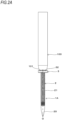
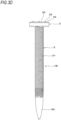
- FIG. 3A is a perspective view showing an example of a screw nail according to a second embodiment
- FIG. 3B is a plan view showing the example of the screw nail according to the second embodiment
- FIG. 3C is a cross-sectional view taken along an X-X line in FIG. 3B
- FIG. 3D is a side view showing the example of the screw nail according to the second embodiment.
- a screw nail 1B has three convex portions 32 formed on the end face 30 of the head portion 3.
- the three convex portions 32 are formed at equal intervals along the circumferential direction of the head portion 3 on a concentric circle centered on a rotational axis O of the screw nail 1B. Note that, the number of the convex portions 32 may also be four or more.
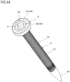
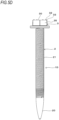
- FIG. 4A is a perspective view showing an example of a screw nail according to a third embodiment
- FIG. 4B is a plan view showing the example of the screw nail according to the third embodiment
- FIG. 4C is a cross-sectional view taken along an X-X line in FIG. 4B
- FIG. 4D is a side view showing the example of the screw nail according to the third embodiment.
- a convex portion 32 protruding from the end surface 30 of the head portion 3 is continuously formed in the circumferential direction of the head portion 3 up to a region beyond a half region divided by an arbitrary center line on the end surface 30 of the head portion 3.
- the convex portion 32 may have an annularly continuing shape or a partially notched shape such as a C-shape, as long as a virtual plane tangent to the vertex of the convex portion 32 continuing beyond the half region of the end face 30, which is a virtual plane specified by the vertex of the convex portion 32, has a shape orthogonal to the axis direction of the nail shaft portion 2.
- the opening exposed on the end face 30 may have a polygonal shape such as a hexagon, or a shape in which a portion between vertexes is concave in a central direction, such as a star shape, in addition to the square shape.
- the convex portion 32 may be formed at positions facing vertexes of a polygonal shape or a star shape, at positions facing sides between vertexes of a polygonal shape or at positions corresponding to concave portions between vertexes.
- FIG. 5A is a perspective view showing an example of a screw nail according to a fourth embodiment
- FIG. 5B is a plan view showing the example of the screw nail according to the fourth embodiment
- FIG. 5C is a cross-sectional view taken along an X-X line in FIG. 5B
- FIG. 5D is a side view showing the example of the screw nail according to the fourth embodiment.
- FIG. 6A is a perspective view showing an example of a screw nail according to a fifth embodiment
- FIG. 6B is a plan view showing the example of the screw nail according to the fifth embodiment
- FIG. 6C is a cross-sectional view taken along an X-X line in FIG. 6B
- FIG. 6D is a side view showing the example of the screw nail according to the fifth embodiment.
- Screw nails 1D and 1E are each formed with an engaging portion 35 serving as a polygonal outer periphery of the head portion 3 and capable of engaging a rotary tool (not shown).
- the engaging portion 35 has a hexagonal shape in this example.
- the head portion 3 may be formed, between the engaging portion 35 and the nail shaft portion 2, with a flange portion having a circular shape or the like whose diameter is enlarged in the radial direction with respect to the engaging portion 35.
- the screw nails 1D and 1E each have convex portions 32 provided on the end face 30 of the head portion 3 and protruding along the axis direction of the nail shaft portion 2 in the direction opposite to the direction in which the nail shaft portion 2 protrudes from the head portion 3.
- the screw nail 1D has six convex portions 32 at positions, each facing a side between the vertexes of the polygonal engaging portion 35, on the end face 30 of the head portion 3.
- the screw nail 1D is formed with a concave portion 33 outside each convex portion 32 with respect to the radial direction of the head portion 3.
- the screw nail 1E has six convex portions 32 at positions, each facing each vertex of the polygonal engaging portion 35, on the end face 30 of the head portion 3.
- the screw nail 1E is formed with a concave portion 33 outside each convex portion 32 with respect to the radial direction of the head portion 3.
- the concave portion 33 is formed between the convex portions 32 and the engaging portion 35.
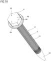
- FIG. 7A is a perspective view showing an example of a screw nail according to a sixth embodiment
- FIG. 7B is a plan view showing the example of the screw nail according to the sixth embodiment
- FIG. 7C is a cross-sectional view taken along an X-X line in FIG. 7B
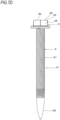
- FIG. 7D is a side view showing the example of the screw nail according to the sixth embodiment.
- a screw nail 1F is formed, on the end face 30 of the head portion 3, with three convex portions 32 at positions facing three vertexes located on an equilateral triangle among vertexes of a hexagonal engaging portion 35, and concave portions 33 between the respective convex portions 32 and the engaging portion 35.
- the convex portion 32 may be formed at the position facing a desired side among the sides between the respective vertexes of the polygonal engaging portion 35 or at the position facing a desired vertex among the respective vertexes of the polygonal engaging portion 35.
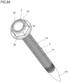
- FIG. 8A is a perspective view showing an example of a screw nail according to a seventh embodiment
- FIG. 8B is a plan view showing the example of the screw nail according to the seventh embodiment
- FIG. 8C is a cross-sectional view taken along an X-X line in FIG. 8B
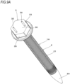
- FIG. 8D is a side view showing the example of the screw nail according to the seventh embodiment.
- a screw nail 1G is formed with an engaging portion 35 serving as the polygonal outer periphery of the head portion 3, and a convex portion 32 protruding from the end surface 30 of the head portion 3 and formed continuously in the circumferential direction of the head portion 3.
- the screw nail 1G is formed with a concave portion 33 between the convex portion 32 and the engaging portion 35.
- the convex portion 32 may have an annularly continuing shape or a partially notched shape such as a C-shape.
- FIG. 9A is a perspective view showing an example of a screw nail according to an eighth embodiment
- FIG. 9B is a plan view showing the example of the screw nail according to the eighth embodiment
- FIG. 9C is a cross-sectional view taken along an X-X line in FIG. 9B
- FIG. 9D is a side view showing the example of the screw nail according to the eighth embodiment.
- a screw nail 1H is formed with an engaging portion 35 serving as the polygonal outer periphery of the head portion 3, and has two convex portions 32 provided on the end face 30 of the head portion 3 and protruding along the axis direction of the nail shaft portion 2 in the direction opposite to the direction in which the nail shaft portion 2 protrudes from the head portion 3.
- the screw nail 1H is formed with a concave portion 33 between the convex portion 32 and the engaging portion 35.
- the two convex portions 32 may be provided.
- FIG. 10A is a perspective view showing an example of a screw nail according to a ninth embodiment
- FIG. 10B is a plan view showing the example of the screw nail according to the ninth embodiment
- FIG. 10C is a cross-sectional view taken along an X-X line in FIG. 10B
- FIG. 10D is a side view showing the example of the screw nail according to the ninth embodiment.
- a screw nail 1I is formed with an engaging portion 35 serving as the polygonal outer periphery of the head portion 3, and has a convex portion 32 provided on the end face 30 of the head portion 3 and protruding along the axis direction of the nail shaft portion 2 in the direction opposite to the direction in which the nail shaft portion 2 protrudes from the head portion 3.
- the convex portion 32 is formed in a cross shape, when seeing the end surface 30 of the head portion 3 from the axis direction.
- the screw nail 1I is formed with a concave portion 33 between the convex portion 32 and the engaging portion 35. Note that, a center of the cross may be formed with a concave portion.
- FIG. 11A is a perspective view showing an example of a screw nail according to a tenth embodiment
- FIG. 11B is a plan view showing the example of the screw nail according to the tenth embodiment
- FIG. 11C is a cross-sectional view taken along an X-X line in FIG. 11B
- FIG. 11D is a side view showing the example of the screw nail according to the tenth embodiment.
- a screw nail 1J is formed with an engaging portion 35 serving as the polygonal outer periphery of the head portion 3, and has a convex portion 32 provided on the end face 30 of the head portion 3 and protruding along the axis direction of the nail shaft portion 2 in the direction opposite to the direction in which the nail shaft portion 2 protrudes from the head portion 3.
- the convex portion 32 is formed in an arbitrary alphabet shape, when seeing the end face 30 of the head portion 3 from the axis direction.
- the screw nail 1J is formed with a concave portion 33 between the convex portion 32 and the engaging portion 35.
- the alphabet may have a partially notched shape.
- a character other than alphabets or a number may also be used.
- the convex portion 32 comes into contact with a striking tool configured to strike the head portion of the screw nail in each of the half regions divided by the arbitrary center line on the end face 30 of the head portion 3.
- the height of the convex portion 32 is set such that a virtual plane tangent to the vertexes of the convex portion 32, which is a virtual plane specified by the vertexes of the convex portion 32, is orthogonal to the axis of the screw nail.
Landscapes
- Engineering & Computer Science (AREA)
- General Engineering & Computer Science (AREA)
- Mechanical Engineering (AREA)
- Portable Nailing Machines And Staplers (AREA)
Abstract
Description
- The present invention relates to a screw nail that is used for fastening steel plates, or the like.
- "Screws" that can be re-tightened or removed are often used to fasten steel plates that are used in roof construction or the like. However, construction with screws requires drilling prepared holes or screwing while cutting a tap, resulting in poor workability.
- As a solution to such problem, a screw nail capable of being struck with a tool configured to operate by a motor, an air pressure, a combustion pressure of gas, or the like and being pulled out by rotating the screw nail like a "screw" upon pullout has been suggested.
- When using a screw nail to fasten steel plates, it is necessarily required to transmit high torque. Therefore, a screw nail having a "square hole or hexagon hole recess" or a "hexagon head" with excellent torque transmission, instead of a "cross groove recess", is used.
- A "square hole" or "hexagon hole" recess suitable for transmission of high torque has a feature that a clearance between a bit and the recess is smaller than that of the "cross groove" recess. However, for the screw nail, there is a problem that the recess may be deformed due to impact at the time of striking, and therefore, the bit does not fit into the recess.
- Accordingly, a technology of forming an annular protrusion serving as a crushing margin on an outer periphery of a head portion of a screw nail has been suggested (refer to
Japanese Patent No. 4,144,408 Japanese Unexamined Utility Model Application Publication No. H06-35630 - However, in the configuration in which the annular protrusion is provided on the outer periphery of the head portion, the protrusion is crushed upon striking and spreads outward of the head portion, resulting in a larger head diameter and a poor appearance. In addition, when the crushed protrusion sticks out in a form of burr outward from the outer periphery of the head portion, the protrusion may come into contact with a surrounding member or the like and exert an influence. Further, in the case of a screw nail having a "hexagon head", as a diameter of the head increases, a socket does not enter, and therefore, the screw nail cannot be loosened. Further, if a screw having one or two protrusions provided on the upper surface of the head portion is used as a screw nail, when the screw nail and an axis of a screwdriver are misaligned, a striking surface of the screwdriver strikes only a part of the head portion of the screw nail, so that a striking force cannot be transmitted in an axis direction, and therefore, the screw nail may be tilted.
- The present invention has been made in view of the above problems, and an object thereof is to provide a screw nail capable of suppressing tilting upon striking while suppressing an influence of deformation due to striking.
- According to the present invention, there is provided a screw nail including a nail shaft portion extending along one direction, and a head portion. The diameter of the head portion is enlarged along other direction orthogonal to an extension direction of the nail shaft portion. A sharp tip end portion is formed on one end side of the nail shaft portion along the extension direction, and the head portion is formed at an end portion on the other end side. The nail shaft portion is formed with a screw thread between the tip end portion and the head portion, and the head portion is formed with an engaging portion capable of engaging with a rotary tool. A convex portion protruding along an axis direction of the nail shaft portion is formed on an end surface of the head portion on an opposite side to a side from which the nail shaft portion protrudes. A concave portion that is concave with respect to the convex portion along the axis direction of the nail shaft portion is formed between the convex portion and the engaging portion. A virtual plane specified by vertexes of the convex portion is a plane orthogonal to the axis direction of the nail shaft portion.
- In the present invention, the concave portion is formed between the convex portion that is struck by the striking tool and the engaging portion. Therefore, even when the convex portion is deformed by striking, a factor of hindering engagement between the rotary tool configured to rotate the screw nail and the engaging portion of the screw nail is excluded. In addition, the virtual plane specified by the vertex of the convex portion is orthogonal to the axis direction of the nail shaft portion, whereby a striking force is transmitted to the axis direction of the screw nail.
- According to the present invention, it is possible to suppress an influence of deformation of the convex portion formed on the head portion of the screw nail due to the striking, and to maintain a state in which the rotary tool configured to rotate the screw nail and the engaging portion of the screw nail can be engaged. In addition, it is possible to suppress the screw nail from being tilted upon striking.
-
-
FIG. 1A is a perspective view showing an example of a screw nail according to a first embodiment. -
FIG. 1B is a plan view showing the example of the screw nail according to the first embodiment. -
FIG. 1C is a cross-sectional view taken along an X-X line inFIG. 1B . -
FIG. 1D is a side view showing the example of the screw nail according to the first embodiment. -
FIG. 2A illustrates a relationship between a screwdriver configured to strike a screw nail and a screw nail. -
FIG. 2B illustrates a relationship between the screwdriver configured to strike a screw nail and the screw nail. -
FIG. 2C illustrates a relationship between the screwdriver configured to strike a screw nail and the screw nail. -
FIG. 2D illustrates a relationship between the screwdriver configured to strike a screw nail and the screw nail. -
FIG. 2E illustrates a relationship between the screwdriver configured to strike a screw nail and the screw nail. -
FIG. 3A is a perspective view showing an example of a screw nail according to a second embodiment. -
FIG. 3B is a plan view showing the example of the screw nail according to the second embodiment. -
FIG. 3C is a cross-sectional view taken along an X-X line inFIG. 3B . -
FIG. 3D is a side view showing the example of the screw nail according to the second embodiment. -
FIG. 4A is a perspective view showing an example of a screw nail according to a third embodiment. -
FIG. 4B is a plan view showing the example of the screw nail according to the third embodiment. -
FIG. 4C is a cross-sectional view taken along an X-X line inFIG. 4B . -
FIG. 4D is a side view showing the example of the screw nail according to the third embodiment. -
FIG. 5A is a perspective view showing an example of a screw nail according to a fourth embodiment. -
FIG. 5B is a plan view showing the example of the screw nail according to the fourth embodiment. -
FIG. 5C is a cross-sectional view taken along an X-X line inFIG. 5B . -
FIG. 5D is a side view showing the example of the screw nail according to the fourth embodiment. -
FIG. 6A is a perspective view showing an example of a screw nail according to a fifth embodiment. -
FIG. 6B is a plan view showing the example of the screw nail according to the fifth embodiment. -
FIG. 6C is a cross-sectional view taken along an X-X line inFIG. 6B . -
FIG. 6D is a side view showing the example of the screw nail according to the fifth embodiment. -
FIG. 7A is a perspective view showing an example of a screw nail according to a sixth embodiment. -
FIG. 7B is a plan view showing the example of the screw nail according to the sixth embodiment. -
FIG. 7C is a cross-sectional view taken along an X-X line inFIG. 7B . -
FIG. 7D is a side view showing the example of the screw nail according to the sixth embodiment. -
FIG. 8A is a perspective view showing an example of a screw nail according to a seventh embodiment. -
FIG. 8B is a plan view showing the example of the screw nail according to the seventh embodiment. -
FIG. 8C is a cross-sectional view taken along an X-X line inFIG. 8B . -
FIG. 8D is a side view showing the example of the screw nail according to the seventh embodiment. -
FIG. 9A is a perspective view showing an example of a screw nail according to an eighth embodiment. -
FIG. 9B is a plan view showing the example of the screw nail according to the eighth embodiment. -
FIG. 9C is a cross-sectional view taken along an X-X line inFIG. 9B . -
FIG. 9D is a side view showing the example of the screw nail according to the eighth embodiment. -
FIG. 10A is a perspective view showing an example of a screw nail according to a ninth embodiment. -
FIG. 10B is a plan view showing the example of the screw nail according to the ninth embodiment. -
FIG. 10C is a cross-sectional view taken along an X-X line inFIG. 10B . -
FIG. 10D is a side view showing the example of the screw nail according to the ninth embodiment. -
FIG. 11A is a perspective view showing an example of a screw nail according to a tenth embodiment. -
FIG. 11B is a plan view showing the example of the screw nail according to the tenth embodiment. -
FIG. 11C is a cross-sectional view taken along an X-X line inFIG. 11B . -
FIG. 11D is a side view showing the example of the screw nail according to the tenth embodiment. - Hereinafter, embodiments of the screw nail of the present invention will be described with reference to the drawings.
-
FIG. 1A is a perspective view showing an example of a screw nail according to a first embodiment,FIG. 1B is a plan view showing the example of the screw nail according to the first embodiment,FIG. 1C is a cross-sectional view taken along an X-X line inFIG. 1B , andFIG. 1D is a side view showing the example of the screw nail according to the first embodiment. - A
screw nail 1A includes anail shaft portion 2 extending along one direction indicated by arrows A1 and A2, and ahead portion 3 having a diameter enlarged along other direction indicated by arrows B1 and B2 orthogonal to the extension direction of thenail shaft portion 2 with respect to thenail shaft portion 2. - The
screw nail 1A is formed with atip end portion 20 on one end side indicated by the arrow A1 along the extension direction of thenail shaft portion 2. Thetip end portion 20 has an end portion provided on one end side of thenail shaft portion 2 and formed into a sharp shape capable of being struck into a fastening target. - In addition, the
screw nail 1A is formed with thehead portion 3 at an end portion on the other end side indicated by the arrow A2 along the extension direction of thenail shaft portion 2. Further, thescrew nail 1A has ascrew thread 21 formed at thenail shaft portion 2 along the extension direction of thenail shaft portion 2 between thetip end portion 20 and thehead portion 3. - The
screw nail 1A has an engagingportion 31 formed on anend face 30 of thehead portion 3 on an opposite side to a side from which thenail shaft portion 2 protrudes and capable of engaging with a rotary tool (not shown). The engagingportion 31 is configured as a hole having a predetermined shape in which an opening having at least three vertexes is exposed on theend face 30 of thehead portion 3. In the case in which a bit (not shown) as a rotary tool has a square cross-sectional shape, the engagingportion 31 is configured by providing a square hole as an opening exposed on theend surface 30. The engagingportion 31 formed by providing theend face 30 of thehead portion 3 with a hole having a predetermined shape adapted to the rotary tool in this way is referred to as a recess. - The
screw nail 1A has aconvex portion 32 provided on theend face 30 of thehead portion 3 and protruding along an axis direction of thenail shaft portion 2 in a direction opposite to a direction in which thenail shaft portion 2 protrudes from thehead portion 3. Thescrew nail 1A has at least threeconvex portions 32 formed on theend face 30 of thehead portion 3. The three or moreconvex portions 32 are formed at equal intervals along a circumferential direction of thehead portion 3 on a concentric circle centered on a rotational axis O of thescrew nail 1A. - Thereby, on the
end face 30 of thehead portion 3, at least oneconvex portion 32 is located on one of half regions divided by an arbitrary center line, and the remainingconvex portions 32 are located on the other of the half regions. The arbitrary center line may be a line passing through a center of thehead portion 3. Therefore, theconvex portions 32 come into contact with a striking tool configured to strike the head portion of thescrew nail 1A in each of the half regions divided by the arbitrary center line on theend face 30 of thehead portion 3. - Therefore, in an operation of striking the
head portion 3 of thescrew nail 1A with a striking tool, the striking tool strikes eachconvex portion 32, whereby a striking force can be transmitted in the axis direction of thescrew nail 1A. - In the example shown in
FIGS. 1A ,1B ,1C and1D , thescrew nail 1A has the fourconvex portions 32 formed on theend face 30 of thehead portion 3. The fourconvex portions 32 are formed at equal intervals along the circumferential direction of thehead portion 3 on the concentric circle centered on the rotational axis O of thescrew nail 1A. - The
screw nail 1A has aconcave portion 33, which is concave with respect to theconvex portion 32 along the axis direction of thenail shaft portion 2 and is formed outside eachconvex portion 32 with respect to a radial direction of thehead portion 3 along the other direction indicated by the arrows B1 and B2 orthogonal to the extension direction of thenail shaft portion 2. In addition, aconcave portion 34 concave with respect to theconvex portions 32 along the axis direction of thenail shaft portion 2 is formed inside eachconvex portion 32. In a configuration of thescrew nail 1A in which theend face 30 of thehead portion 3 is drilled to form the engagingportion 31, theconcave portion 33 and theconcave portion 34 are formed by the same surface connecting to theend face 30, and are portions of theend face 30. Further, in the configuration of thescrew nail 1A in which theend face 30 of thehead portion 3 is drilled to form the engagingportion 31, theconcave portion 34 is formed between theconvex portion 32 and the engagingportion 31. - As shown in
FIG. 1B and the like, in the case in which the engagingportion 31 is a hole formed in theend face 30 of thehead portion 3 and an opening exposed on theend face 30 has a square shape, the fourconvex portions 32 are provided at positions facing eachside 31a of the square shape. - Thereby, as compared with a configuration in which the four
convex portions 32 are provided atpositions facing vertexes 31b of the square shape, eachconvex portion 32 can be located on a circumcircle C1 passing through eachvertex 31b of the engagingportion 31 while securing a dimension of theconcave portion 34 between the engagingportion 31 and theconvex portion 32, and theconvex portion 32 can be arranged close to a center of thehead portion 3 in the radial direction. In addition, a dimension of theconcave portion 33 between an outer periphery of thehead portion 3 and theconvex portion 32 can be secured. - Therefore, even when the
convex portions 32 formed on thehead portion 3 of thescrew nail 1A are deformed by being struck with the striking tool, since theconcave portion 34 is formed between theconvex portions 32 and the engagingportion 31, the engagingportion 31 is suppressed from being deformed, and a state in which the rotary tool (bit) configured to rotate thescrew nail 1A and the engagingportion 31 of thescrew nail 1A can be engaged can be maintained. - Note that, in the case in which the engaging
portion 31 is a hole formed in theend face 30 of thehead portion 3 and the opening exposed on theend face 30 has a square shape, the fourconvex portions 32 may be provided at positions facing eachvertex 31b of the square shape. In this case, eachconvex portion 32 is positioned outside the circumcircle C1 passing through eachvertex 31b of the engagingportion 31 . -
FIGS. 2A ,2B ,2C ,2D and2E illustrate a relationship between a screwdriver configured to strike a screw nail and a screw nail. As a striking tool configured to strike theend face 30 of thehead portion 3, a tool configured to actuate ascrewdriver 100 as shown inFIG. 2A , which is configured to strike theend face 30 of thehead portion 3 of thescrew nail 1A, by a motor, an air pressure, a combustion pressure of gas, or the like is known. In such a tool, since thescrewdriver 100 passes through a passage through which thescrew nail 1A is struck out, a diameter of thescrewdriver 100 is about equal to or less than a diameter of thehead portion 3, and a diameter of astriking surface 101 of thescrewdriver 100 is smaller than a diameter of theend face 30 of thehead portion 3. - As shown in
FIG. 2B , for a tool using thescrew nail 1A whose diameter D1 of theend face 30 of thehead portion 3 is about 8.5 mm, a diameter D2 of thestriking surface 101 of thescrewdriver 100 is about 7 mm, as shown inFIG. 2C . For this reason, when an area of theend face 30 of thehead portion 3 is assumed as 100%, an area of the striking surface of thescrewdriver 100 is about 68%. - Further, as shown in
FIG. 2D , in a tool passage (not shown) through which thescrew nail 1A and thescrewdriver 100 pass, a relative movable amount L between thescrew nail 1A and thescrewdriver 100 along the radial direction of thehead portion 3 is about 1 mm. - Thereby, as shown in
FIG. 2E , when thescrew nail 1A and thescrewdriver 100 relatively move by the maximum movable amount L along the radial direction of thehead portion 3, an overlapping area S of theend face 30 of thehead portion 3 and thestriking surface 101 of thescrewdriver 100 is about 66%. - Since the
concave portion 33 is formed outside eachconvex portion 32 with respect to the radial direction of thehead portion 3, when the area of theend face 30 of thehead portion 3 is assumed as 100%, eachconvex portion 32 and thestriking surface 101 of thescrewdriver 100 come into contact with each other in the case of a configuration in which three or moreconvex portions 32 are located within a range of an area equal to or less than 64% of the area of theend face 30 and outside the engagingportion 31. - Thereby, as shown in
FIG. 2D , even when thescrew nail 1A and thescrewdriver 100 relatively move by the maximum movable amount L along the radial direction of thehead portion 3, in the operation of striking thehead portion 3 of thescrew nail 1A with thescrewdriver 100, thescrewdriver 100 strikes eachconvex portion 32, whereby the striking force can be transmitted in the axis direction of thescrew nail 1A. - Note that, for the
screw nail 1A whose diameter D1 of theend face 30 of thehead portion 3 is about 8.5 mm, a diameter of the circumcircle C1 passing through eachvertex 31b of the engagingportion 31 is about 4.2 mm. For this reason, in the case in which the diameter D2 of thestriking surface 101 of thescrewdriver 100 is about 7 mm, when theconvex portions 32 are formed within a circle having a diameter of 4.2 mm or more and 7 mm or less from the center of thehead portion 3, eachconvex portion 32 and thestriking surface 101 of thescrewdriver 100 come into contact with each other. - Note that, in the case in which the striking tool configured to strike the
end face 30 of thehead portion 3 is a hammer that strikes thescrew nail 1A with a force of the hand, a diameter of a striking surface of the hammer is generally greater than the diameter of thehead portion 3. Thereby, in an operation of striking thehead portion 3 of thescrew nail 1A with a hammer, eachconvex portion 32 and the striking surface of the hammer come into contact with each other. - Further, in the case of a tool configured to actuate the
screwdriver 100 for striking theend surface 30 of thehead portion 3 with a motor, an air pressure, a combustion pressure of gas, or the like, a force with which thescrewdriver 100 strikes theconvex portions 32 of thehead portion 3 is about 1500N or more and 3000N or less. Therefore, protrusion heights of theconvex portions 32 from theend surface 30 are set to 0.5 mm or more and 1.5 mm or less. Note that, when using a hammer whose weight of a striking part is about 400g, it is considered that a striking force of about 500N is generated. - Thereby, when the protrusion heights of the
convex portions 32 from theend surface 30 are set to 0.5 mm or more and 1.5 mm or less, the striking tool does not directly strike theend surface 30 of thehead portion 3, so that the engagingportion 31 or an external appearance of the head portion is suppressed from being deformed. In addition, since theconvex portions 32 are arranged on the inner side spaced from the outer periphery of thehead portion 3 by a predetermined amount, even when theconvex portions 32 are crushed and deformed, the crushedconvex portions 32 are suppressed from sticking out in a form of burr outward from the outer periphery of thehead portion 3. Therefore, occurrence of a poor appearance in which the burr-shaped crushedconvex portions 32 stick out outward from the outer periphery of thehead portion 3 is suppressed, and the crushedconvex portions 32 sticking out in a burr shape are suppressed from affecting a surrounding member, and the like. - Further, in the
screw nail 1A, the height of eachconvex portion 32 from theend face 30 is set so that a virtual plane H1 tangent to the vertexes of the three or moreconvex portions 32, which is a virtual plane specified by the vertexes of theconvex portions 32, is orthogonal to the axis O of thescrew nail 1A. Thereby, in the operation of striking thehead portion 3 of thescrew nail 1A with the striking tool, the striking tool strikes eachconvex portion 32, whereby the striking force can be transmitted in the axis direction of thescrew nail 1A. -
FIG. 3A is a perspective view showing an example of a screw nail according to a second embodiment,FIG. 3B is a plan view showing the example of the screw nail according to the second embodiment,FIG. 3C is a cross-sectional view taken along an X-X line inFIG. 3B , andFIG. 3D is a side view showing the example of the screw nail according to the second embodiment. - A
screw nail 1B has threeconvex portions 32 formed on theend face 30 of thehead portion 3. The threeconvex portions 32 are formed at equal intervals along the circumferential direction of thehead portion 3 on a concentric circle centered on a rotational axis O of thescrew nail 1B. Note that, the number of theconvex portions 32 may also be four or more. -
FIG. 4A is a perspective view showing an example of a screw nail according to a third embodiment,FIG. 4B is a plan view showing the example of the screw nail according to the third embodiment,FIG. 4C is a cross-sectional view taken along an X-X line inFIG. 4B , andFIG. 4D is a side view showing the example of the screw nail according to the third embodiment. - For a
screw nail 1C, aconvex portion 32 protruding from theend surface 30 of thehead portion 3 is continuously formed in the circumferential direction of thehead portion 3 up to a region beyond a half region divided by an arbitrary center line on theend surface 30 of thehead portion 3. Theconvex portion 32 may have an annularly continuing shape or a partially notched shape such as a C-shape, as long as a virtual plane tangent to the vertex of theconvex portion 32 continuing beyond the half region of theend face 30, which is a virtual plane specified by the vertex of theconvex portion 32, has a shape orthogonal to the axis direction of thenail shaft portion 2. - In the case in which the engaging
portion 31 is a hole formed in theend face 30 of thehead portion 3, the opening exposed on theend face 30 may have a polygonal shape such as a hexagon, or a shape in which a portion between vertexes is concave in a central direction, such as a star shape, in addition to the square shape. Theconvex portion 32 may be formed at positions facing vertexes of a polygonal shape or a star shape, at positions facing sides between vertexes of a polygonal shape or at positions corresponding to concave portions between vertexes. -
FIG. 5A is a perspective view showing an example of a screw nail according to a fourth embodiment,FIG. 5B is a plan view showing the example of the screw nail according to the fourth embodiment,FIG. 5C is a cross-sectional view taken along an X-X line inFIG. 5B , andFIG. 5D is a side view showing the example of the screw nail according to the fourth embodiment. - In addition,
FIG. 6A is a perspective view showing an example of a screw nail according to a fifth embodiment,FIG. 6B is a plan view showing the example of the screw nail according to the fifth embodiment,FIG. 6C is a cross-sectional view taken along an X-X line inFIG. 6B , andFIG. 6D is a side view showing the example of the screw nail according to the fifth embodiment. - Screw nails 1D and 1E are each formed with an engaging
portion 35 serving as a polygonal outer periphery of thehead portion 3 and capable of engaging a rotary tool (not shown). The engagingportion 35 has a hexagonal shape in this example. Thehead portion 3 may be formed, between the engagingportion 35 and thenail shaft portion 2, with a flange portion having a circular shape or the like whose diameter is enlarged in the radial direction with respect to the engagingportion 35. - The screw nails 1D and 1E each have
convex portions 32 provided on theend face 30 of thehead portion 3 and protruding along the axis direction of thenail shaft portion 2 in the direction opposite to the direction in which thenail shaft portion 2 protrudes from thehead portion 3. Thescrew nail 1D has sixconvex portions 32 at positions, each facing a side between the vertexes of the polygonal engagingportion 35, on theend face 30 of thehead portion 3. In addition, thescrew nail 1D is formed with aconcave portion 33 outside eachconvex portion 32 with respect to the radial direction of thehead portion 3. Thescrew nail 1E has sixconvex portions 32 at positions, each facing each vertex of the polygonal engagingportion 35, on theend face 30 of thehead portion 3. In addition, thescrew nail 1E is formed with aconcave portion 33 outside eachconvex portion 32 with respect to the radial direction of thehead portion 3. In this way, in the configuration in which the engagingportion 35 is formed as the polygonal outer periphery of thehead portion 3, theconcave portion 33 is formed between theconvex portions 32 and the engagingportion 35. - Therefore, even when the
convex portions 32 formed on thehead portion 3 of each of the screw nails 1D and 1E are deformed by being struck with the striking tool, since theconcave portion 33 is formed between theconvex portions 32 and the engagingportion 35, the engagingportion 35 is suppressed from being deformed, and a state in which the rotary tool (socket) configured to rotate the screw nails 1D and 1E and the engagingportion 35 of each of the screw nails 1D and 1E can be engaged can be maintained. -
FIG. 7A is a perspective view showing an example of a screw nail according to a sixth embodiment,FIG. 7B is a plan view showing the example of the screw nail according to the sixth embodiment,FIG. 7C is a cross-sectional view taken along an X-X line inFIG. 7B , andFIG. 7D is a side view showing the example of the screw nail according to the sixth embodiment. - A
screw nail 1F is formed, on theend face 30 of thehead portion 3, with threeconvex portions 32 at positions facing three vertexes located on an equilateral triangle among vertexes of a hexagonal engagingportion 35, andconcave portions 33 between the respectiveconvex portions 32 and the engagingportion 35. In this way, in the case of the screw nail in which the engagingportion 35 is formed as the polygonal outer periphery of thehead portion 3, theconvex portion 32 may be formed at the position facing a desired side among the sides between the respective vertexes of the polygonal engagingportion 35 or at the position facing a desired vertex among the respective vertexes of the polygonal engagingportion 35. -
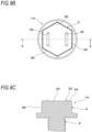
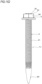
FIG. 8A is a perspective view showing an example of a screw nail according to a seventh embodiment,FIG. 8B is a plan view showing the example of the screw nail according to the seventh embodiment,FIG. 8C is a cross-sectional view taken along an X-X line inFIG. 8B , andFIG. 8D is a side view showing the example of the screw nail according to the seventh embodiment. - A
screw nail 1G is formed with an engagingportion 35 serving as the polygonal outer periphery of thehead portion 3, and aconvex portion 32 protruding from theend surface 30 of thehead portion 3 and formed continuously in the circumferential direction of thehead portion 3. In addition, thescrew nail 1G is formed with aconcave portion 33 between theconvex portion 32 and the engagingportion 35. Theconvex portion 32 may have an annularly continuing shape or a partially notched shape such as a C-shape. -
FIG. 9A is a perspective view showing an example of a screw nail according to an eighth embodiment,FIG. 9B is a plan view showing the example of the screw nail according to the eighth embodiment,FIG. 9C is a cross-sectional view taken along an X-X line inFIG. 9B , andFIG. 9D is a side view showing the example of the screw nail according to the eighth embodiment. - A
screw nail 1H is formed with an engagingportion 35 serving as the polygonal outer periphery of thehead portion 3, and has twoconvex portions 32 provided on theend face 30 of thehead portion 3 and protruding along the axis direction of thenail shaft portion 2 in the direction opposite to the direction in which thenail shaft portion 2 protrudes from thehead portion 3. In addition, thescrew nail 1H is formed with aconcave portion 33 between theconvex portion 32 and the engagingportion 35. As long as theconvex portions 32 extend along theend face 30 of thehead portion 3, are located on both one and the other of half regions divided by an arbitrary center line on theend face 30 of thehead portion 3, and are tangential to thestriking surface 101 of thescrewdriver 100 shown inFIGS. 2A and the like in a linear shape and a virtual plane tangent to the vertexes of theconvex portions 32 located on both one and the other of the half regions of theend face 30, which is a virtual plane specified by the vertexes of theconvex portions 32, is orthogonal to the axis direction of thenail shaft portion 2, the twoconvex portions 32 may be provided. -
FIG. 10A is a perspective view showing an example of a screw nail according to a ninth embodiment,FIG. 10B is a plan view showing the example of the screw nail according to the ninth embodiment,FIG. 10C is a cross-sectional view taken along an X-X line inFIG. 10B , andFIG. 10D is a side view showing the example of the screw nail according to the ninth embodiment. - A
screw nail 1I is formed with an engagingportion 35 serving as the polygonal outer periphery of thehead portion 3, and has aconvex portion 32 provided on theend face 30 of thehead portion 3 and protruding along the axis direction of thenail shaft portion 2 in the direction opposite to the direction in which thenail shaft portion 2 protrudes from thehead portion 3. Theconvex portion 32 is formed in a cross shape, when seeing theend surface 30 of thehead portion 3 from the axis direction. In addition, thescrew nail 1I is formed with aconcave portion 33 between theconvex portion 32 and the engagingportion 35. Note that, a center of the cross may be formed with a concave portion. -
FIG. 11A is a perspective view showing an example of a screw nail according to a tenth embodiment,FIG. 11B is a plan view showing the example of the screw nail according to the tenth embodiment,FIG. 11C is a cross-sectional view taken along an X-X line inFIG. 11B , andFIG. 11D is a side view showing the example of the screw nail according to the tenth embodiment. - A
screw nail 1J is formed with an engagingportion 35 serving as the polygonal outer periphery of thehead portion 3, and has aconvex portion 32 provided on theend face 30 of thehead portion 3 and protruding along the axis direction of thenail shaft portion 2 in the direction opposite to the direction in which thenail shaft portion 2 protrudes from thehead portion 3. Theconvex portion 32 is formed in an arbitrary alphabet shape, when seeing theend face 30 of thehead portion 3 from the axis direction. In addition, thescrew nail 1J is formed with aconcave portion 33 between theconvex portion 32 and the engagingportion 35. Note that, the alphabet may have a partially notched shape. In addition, a character other than alphabets or a number may also be used. - In this way, in the case of the configuration in which a part of the
convex portion 32 is located on one of the half regions divided by an arbitrary center line and the other part of theconvex portion 32 is located on the other of the half regions on theend face 30 of thehead portion 3, theconvex portion 32 comes into contact with a striking tool configured to strike the head portion of the screw nail in each of the half regions divided by the arbitrary center line on theend face 30 of thehead portion 3. - In addition, the height of the
convex portion 32 is set such that a virtual plane tangent to the vertexes of theconvex portion 32, which is a virtual plane specified by the vertexes of theconvex portion 32, is orthogonal to the axis of the screw nail. Thereby, in the operation of striking the head portion of the screw nail with the striking tool, the striking tool strikes theconvex portion 32, whereby the striking force can be transmitted in the axis direction of the screw nail.
Claims (9)
- A screw nail comprising:a nail shaft portion extending along one direction; anda head portion, the diameter of the head portion being enlarged along other direction orthogonal to an extension direction of the nail shaft portion,wherein a sharp tip end portion is formed on one end side of the nail shaft portion along the extension direction, and the head portion is formed at an end portion on the other end side,wherein the nail shaft portion is formed with a screw thread between the tip end portion and the head portion, and the head portion is formed with an engaging portion capable of engaging with a rotary tool,wherein a convex portion protruding along an axis direction of the nail shaft portion is formed on an end surface of the head portion on an opposite side to a side from which the nail shaft portion protrudes,wherein a concave portion that is concave with respect to the convex portion along the axis direction of the nail shaft portion is formed between the convex portion and the engaging portion, andwherein a virtual plane specified by vertexes of the convex portion is a plane orthogonal to the axis direction of the nail shaft portion.
- The screw nail according to Claim 1, wherein the concave portion is formed outside the convex portion with respect to a radial direction of the head portion.
- The screw nail according to Claim 1 or 2, wherein the concave portion is formed inside the convex portion with respect to a radial direction of the head portion.
- The screw nail according to any one of Claims 1 to 3, wherein at least three convex portions are formed on the end surface of the head portion, at least one convex portion is located on one of half regions divided by an arbitrary center line and the remaining convex portions are located on the other of the half regions on the end surface of the head portion, and a virtual plane tangent to vertexes of the at least three convex portions is orthogonal to the axis direction of the nail shaft portion.
- The screw nail according to any one of Claims 1 to 4, wherein the engaging portion is configured by a hole whose opening having at least three vertexes is exposed on the end surface of the head portion, and
wherein the convex portion is provided at a position corresponding to a side between respective vertexes of the engaging portion. - The screw nail according to Claim 5, wherein the convex portion is located on a circumcircle passing through each vertex of the engaging portion.
- The screw nail according to any one of Claims 1 to 4, wherein the engaging portion is configured by a hole whose opening having at least three vertexes is exposed on the end surface of the head portion, and
wherein the convex portion is located outside a circumcircle passing through each vertex of the engaging portion. - The screw nail according to any one of Claims 1 to 3, wherein the convex portions is located on both one and the other of half regions divided by an arbitrary center line, on the end surface of the head portion, the convex portion located on one or both one and the other of the half regions of the end surface extends along the end surface of the head portion, and a virtual plane tangent to a vertex of the convex portion located on both one side and the other side of the half regions of the end surface is orthogonal to the axis direction of the nail shaft portion.
- The screw nail according to any one of Claims 1 to 3, wherein the convex portion is continuous in a circumferential direction of the head portion up to a region beyond a half region divided by an arbitrary center line on the end surface of the head portion, and a virtual plane tangent to a vertex of the convex portion that is continuous beyond the half region of the end surface is orthogonal to the axis direction of the nail shaft portion.
Applications Claiming Priority (1)
| Application Number | Priority Date | Filing Date | Title |
|---|---|---|---|
| JP2022003587A JP7865012B2 (en) | 2022-01-13 | 2022-01-13 | Screws |
Publications (1)
| Publication Number | Publication Date |
|---|---|
| EP4212742A1 true EP4212742A1 (en) | 2023-07-19 |
Family
ID=84943297
Family Applications (1)
| Application Number | Title | Priority Date | Filing Date |
|---|---|---|---|
| EP23151245.0A Pending EP4212742A1 (en) | 2022-01-13 | 2023-01-12 | Screw nail |
Country Status (3)
| Country | Link |
|---|---|
| US (1) | US12305679B2 (en) |
| EP (1) | EP4212742A1 (en) |
| JP (2) | JP7865012B2 (en) |
Families Citing this family (4)
| Publication number | Priority date | Publication date | Assignee | Title |
|---|---|---|---|---|
| JP7839660B2 (en) * | 2022-03-09 | 2026-04-02 | Bxカネシン株式会社 | Screw screws and how to use screw screws |
| CA228791S (en) * | 2023-09-11 | 2025-05-01 | Lycopodium Minerals Pty Ltd | Fastener |
| USD1088854S1 (en) * | 2024-03-22 | 2025-08-19 | David Cowan | Bolt |
| WO2026122068A1 (en) * | 2024-12-03 | 2026-06-11 | Norm Izmir Civata Sanayi Ticaret Anonim Sirketi | Lightweight fastener with specially shaped head |
Citations (7)
| Publication number | Priority date | Publication date | Assignee | Title |
|---|---|---|---|---|
| JPH0635630U (en) | 1992-10-14 | 1994-05-13 | マックス株式会社 | screw |
| JP4144408B2 (en) | 2003-04-04 | 2008-09-03 | マックス株式会社 | Screw nails for driving |
| JP2010054015A (en) * | 2008-08-29 | 2010-03-11 | Chikateru Otsuki | Screw member and its manufacturing method |
| US10076373B2 (en) * | 2014-03-12 | 2018-09-18 | Intrepid Orthopedics | Self-retaining fastener and driver |
| DE102017119008A1 (en) * | 2017-08-21 | 2019-02-21 | Fischerwerke Gmbh & Co. Kg | nailscrew |
| CN112762076A (en) * | 2019-10-21 | 2021-05-07 | 黄俊铭 | Screw with a thread |
| US20210172468A1 (en) * | 2019-12-05 | 2021-06-10 | AR Developing, LLC | Mechanical fastener drive tool and system |
Family Cites Families (18)
| Publication number | Priority date | Publication date | Assignee | Title |
|---|---|---|---|---|
| US3088361A (en) * | 1958-11-28 | 1963-05-07 | Hallock Robert Lay | Driven fastener |
| US3331274A (en) * | 1965-06-01 | 1967-07-18 | Walton Marvin | Flatheaded one-way screw |
| US3302672A (en) * | 1965-07-12 | 1967-02-07 | Walton Marvin | Screw driving tool |
| JPS6014974Y2 (en) | 1976-09-07 | 1985-05-13 | 日本精線株式会社 | nail head |
| JPS55137709U (en) | 1979-03-24 | 1980-10-01 | ||
| US4911593A (en) * | 1989-05-02 | 1990-03-27 | Kephart R Dewain | Ratchet driven threaded fasteners |
| JPH063563U (en) | 1992-06-23 | 1994-01-18 | 日本電子機器株式会社 | Honing time calculator |
| JPH0665610U (en) | 1993-02-23 | 1994-09-16 | 株式会社クボタ | Ceramic system wall board nails |
| JPH10227305A (en) | 1997-02-14 | 1998-08-25 | Noda Corp | nail |
| US7425112B2 (en) * | 2003-04-29 | 2008-09-16 | Nowak Jr Edmund A | Tamper resistant screw |
| US7997404B2 (en) * | 2006-11-03 | 2011-08-16 | Habasit Ag | Conveyor belt with intermodular supported spheres |
| WO2008058414A1 (en) * | 2006-11-15 | 2008-05-22 | Zed Design Communication Technologies | Slotted screw |
| US8226341B2 (en) * | 2009-02-11 | 2012-07-24 | Illinois Tool Works Inc. | Shock absorbing fastener |
| CN102878176A (en) * | 2011-07-12 | 2013-01-16 | 鸿富锦精密工业(深圳)有限公司 | Screws and heat sink with screws |
| JP6816855B2 (en) * | 2014-12-24 | 2021-01-20 | 富士富株式会社 | Driving type screw nail |
| MX2017010867A (en) * | 2015-02-26 | 2018-01-23 | Cold Heading Company | Lightweight fastener design. |
| JP2017155790A (en) | 2016-02-29 | 2017-09-07 | 恩智製鋲株式会社 | nail |
| US10371189B2 (en) * | 2017-02-22 | 2019-08-06 | Illinois Tool Works Inc. | Nail with a head having an inwardly curved top surface |
-
2022
- 2022-01-13 JP JP2022003587A patent/JP7865012B2/en active Active
-
2023
- 2023-01-09 US US18/094,641 patent/US12305679B2/en active Active
- 2023-01-12 EP EP23151245.0A patent/EP4212742A1/en active Pending
-
2025
- 2025-12-26 JP JP2025284328A patent/JP2026040762A/en active Pending
Patent Citations (7)
| Publication number | Priority date | Publication date | Assignee | Title |
|---|---|---|---|---|
| JPH0635630U (en) | 1992-10-14 | 1994-05-13 | マックス株式会社 | screw |
| JP4144408B2 (en) | 2003-04-04 | 2008-09-03 | マックス株式会社 | Screw nails for driving |
| JP2010054015A (en) * | 2008-08-29 | 2010-03-11 | Chikateru Otsuki | Screw member and its manufacturing method |
| US10076373B2 (en) * | 2014-03-12 | 2018-09-18 | Intrepid Orthopedics | Self-retaining fastener and driver |
| DE102017119008A1 (en) * | 2017-08-21 | 2019-02-21 | Fischerwerke Gmbh & Co. Kg | nailscrew |
| CN112762076A (en) * | 2019-10-21 | 2021-05-07 | 黄俊铭 | Screw with a thread |
| US20210172468A1 (en) * | 2019-12-05 | 2021-06-10 | AR Developing, LLC | Mechanical fastener drive tool and system |
Also Published As
| Publication number | Publication date |
|---|---|
| JP7865012B2 (en) | 2026-05-26 |
| US20230220865A1 (en) | 2023-07-13 |
| US12305679B2 (en) | 2025-05-20 |
| JP2023102869A (en) | 2023-07-26 |
| JP2026040762A (en) | 2026-03-09 |
Similar Documents
| Publication | Publication Date | Title |
|---|---|---|
| US20230220865A1 (en) | Screw nail | |
| US4089357A (en) | Threaded fastener | |
| JP3050542B1 (en) | Screws with holed heads and their driver bits | |
| EP1491777B1 (en) | Tamperproof screw, combination with screwdriver bit, and headrer punch for manufacturing tamperproof screw | |
| JP4801837B2 (en) | A spiral drive system for threaded fasteners | |
| CN106415029B (en) | Screws and drive parts with chamfers | |
| JPH0232397Y2 (en) | ||
| AU2020363401B2 (en) | Thread forming and thread locking fastener | |
| EP0046010B1 (en) | Fastener and driver combination | |
| EP1632683B1 (en) | Fastener-Head, fastener driver-bit and combination | |
| KR20040003032A (en) | Screw tightening structure, screw member, and screw tightening tool | |
| JPH06509859A (en) | Threaded fasteners, especially screws and screw-driving tools | |
| EP3239541B1 (en) | Drivable screw nail | |
| US20070101835A1 (en) | Combination of screw with stabilized strength and screwdriver bit, and header punch for manufacturing the screw with stabilized strength | |
| CA2790954A1 (en) | Drive formation for a rotary drive | |
| JP2011251357A (en) | Impact rotary tool | |
| US4126908A (en) | Threaded fastener recess forming punch | |
| CA2050856A1 (en) | Anchoring device | |
| US20240183379A1 (en) | Flush blind fastener | |
| US20040001740A1 (en) | Cutting insert for a drill, and boring tool using this insert | |
| JP7362109B2 (en) | Water stop bolt member, decorative cap member for scaffold connecting anchor, and method for assembling decorative cap member for scaffold connecting anchor | |
| JP3142191U (en) | Drill bit fixing structure | |
| CA3155261C (en) | Thread forming and thread locking fastener | |
| KR101604979B1 (en) | Self tapping screw | |
| CN101163893A (en) | fastener |
Legal Events
| Date | Code | Title | Description |
|---|---|---|---|
| PUAI | Public reference made under article 153(3) epc to a published international application that has entered the european phase |
Free format text: ORIGINAL CODE: 0009012 |
|
| STAA | Information on the status of an ep patent application or granted ep patent |
Free format text: STATUS: THE APPLICATION HAS BEEN PUBLISHED |
|
| AK | Designated contracting states |
Kind code of ref document: A1 Designated state(s): AL AT BE BG CH CY CZ DE DK EE ES FI FR GB GR HR HU IE IS IT LI LT LU LV MC ME MK MT NL NO PL PT RO RS SE SI SK SM TR |
|
| STAA | Information on the status of an ep patent application or granted ep patent |
Free format text: STATUS: REQUEST FOR EXAMINATION WAS MADE |
|
| 17P | Request for examination filed |
Effective date: 20240119 |
|
| RBV | Designated contracting states (corrected) |
Designated state(s): AL AT BE BG CH CY CZ DE DK EE ES FI FR GB GR HR HU IE IS IT LI LT LU LV MC ME MK MT NL NO PL PT RO RS SE SI SK SM TR |
|
| STAA | Information on the status of an ep patent application or granted ep patent |
Free format text: STATUS: EXAMINATION IS IN PROGRESS |
|
| 17Q | First examination report despatched |
Effective date: 20241223 |