EP4212735A1 - Sealing system for a magnetic levitating centrifugal compressor and a magnetic levitating centrifugal compressor - Google Patents
Sealing system for a magnetic levitating centrifugal compressor and a magnetic levitating centrifugal compressor Download PDFInfo
- Publication number
- EP4212735A1 EP4212735A1 EP22211515.6A EP22211515A EP4212735A1 EP 4212735 A1 EP4212735 A1 EP 4212735A1 EP 22211515 A EP22211515 A EP 22211515A EP 4212735 A1 EP4212735 A1 EP 4212735A1
- Authority
- EP
- European Patent Office
- Prior art keywords
- motor shaft
- seal
- magnet
- sealing system
- centrifugal compressor
- Prior art date
- Legal status (The legal status is an assumption and is not a legal conclusion. Google has not performed a legal analysis and makes no representation as to the accuracy of the status listed.)
- Pending
Links
Images
Classifications
-
- F—MECHANICAL ENGINEERING; LIGHTING; HEATING; WEAPONS; BLASTING
- F04—POSITIVE - DISPLACEMENT MACHINES FOR LIQUIDS; PUMPS FOR LIQUIDS OR ELASTIC FLUIDS
- F04D—NON-POSITIVE-DISPLACEMENT PUMPS
- F04D29/00—Details, component parts, or accessories
- F04D29/08—Sealings
- F04D29/10—Shaft sealings
- F04D29/102—Shaft sealings especially adapted for elastic fluid pumps
-
- F—MECHANICAL ENGINEERING; LIGHTING; HEATING; WEAPONS; BLASTING
- F04—POSITIVE - DISPLACEMENT MACHINES FOR LIQUIDS; PUMPS FOR LIQUIDS OR ELASTIC FLUIDS
- F04D—NON-POSITIVE-DISPLACEMENT PUMPS
- F04D17/00—Radial-flow pumps, e.g. centrifugal pumps; Helico-centrifugal pumps
- F04D17/08—Centrifugal pumps
- F04D17/10—Centrifugal pumps for compressing or evacuating
-
- F—MECHANICAL ENGINEERING; LIGHTING; HEATING; WEAPONS; BLASTING
- F04—POSITIVE - DISPLACEMENT MACHINES FOR LIQUIDS; PUMPS FOR LIQUIDS OR ELASTIC FLUIDS
- F04D—NON-POSITIVE-DISPLACEMENT PUMPS
- F04D25/00—Pumping installations or systems
- F04D25/02—Units comprising pumps and their driving means
- F04D25/06—Units comprising pumps and their driving means the pump being electrically driven
-
- F—MECHANICAL ENGINEERING; LIGHTING; HEATING; WEAPONS; BLASTING
- F04—POSITIVE - DISPLACEMENT MACHINES FOR LIQUIDS; PUMPS FOR LIQUIDS OR ELASTIC FLUIDS
- F04D—NON-POSITIVE-DISPLACEMENT PUMPS
- F04D29/00—Details, component parts, or accessories
- F04D29/05—Shafts or bearings, or assemblies thereof, specially adapted for elastic fluid pumps
- F04D29/056—Bearings
- F04D29/058—Bearings magnetic; electromagnetic
-
- F—MECHANICAL ENGINEERING; LIGHTING; HEATING; WEAPONS; BLASTING
- F16—ENGINEERING ELEMENTS AND UNITS; GENERAL MEASURES FOR PRODUCING AND MAINTAINING EFFECTIVE FUNCTIONING OF MACHINES OR INSTALLATIONS; THERMAL INSULATION IN GENERAL
- F16J—PISTONS; CYLINDERS; SEALINGS
- F16J15/00—Sealings
- F16J15/44—Free-space packings
- F16J15/441—Free-space packings with floating ring
-
- F—MECHANICAL ENGINEERING; LIGHTING; HEATING; WEAPONS; BLASTING
- F16—ENGINEERING ELEMENTS AND UNITS; GENERAL MEASURES FOR PRODUCING AND MAINTAINING EFFECTIVE FUNCTIONING OF MACHINES OR INSTALLATIONS; THERMAL INSULATION IN GENERAL
- F16J—PISTONS; CYLINDERS; SEALINGS
- F16J15/00—Sealings
- F16J15/44—Free-space packings
- F16J15/447—Labyrinth packings
- F16J15/4472—Labyrinth packings with axial path
-
- F—MECHANICAL ENGINEERING; LIGHTING; HEATING; WEAPONS; BLASTING
- F05—INDEXING SCHEMES RELATING TO ENGINES OR PUMPS IN VARIOUS SUBCLASSES OF CLASSES F01-F04
- F05D—INDEXING SCHEME FOR ASPECTS RELATING TO NON-POSITIVE-DISPLACEMENT MACHINES OR ENGINES, GAS-TURBINES OR JET-PROPULSION PLANTS
- F05D2260/00—Function
- F05D2260/30—Retaining components in desired mutual position
- F05D2260/32—Retaining components in desired mutual position by means of magnetic or electromagnetic forces
-
- F—MECHANICAL ENGINEERING; LIGHTING; HEATING; WEAPONS; BLASTING
- F05—INDEXING SCHEMES RELATING TO ENGINES OR PUMPS IN VARIOUS SUBCLASSES OF CLASSES F01-F04
- F05D—INDEXING SCHEME FOR ASPECTS RELATING TO NON-POSITIVE-DISPLACEMENT MACHINES OR ENGINES, GAS-TURBINES OR JET-PROPULSION PLANTS
- F05D2260/00—Function
- F05D2260/30—Retaining components in desired mutual position
- F05D2260/38—Retaining components in desired mutual position by a spring, i.e. spring loaded or biased towards a certain position
-
- Y—GENERAL TAGGING OF NEW TECHNOLOGICAL DEVELOPMENTS; GENERAL TAGGING OF CROSS-SECTIONAL TECHNOLOGIES SPANNING OVER SEVERAL SECTIONS OF THE IPC; TECHNICAL SUBJECTS COVERED BY FORMER USPC CROSS-REFERENCE ART COLLECTIONS [XRACs] AND DIGESTS
- Y02—TECHNOLOGIES OR APPLICATIONS FOR MITIGATION OR ADAPTATION AGAINST CLIMATE CHANGE
- Y02B—CLIMATE CHANGE MITIGATION TECHNOLOGIES RELATED TO BUILDINGS, e.g. HOUSING, HOUSE APPLIANCES OR RELATED END-USER APPLICATIONS
- Y02B30/00—Energy efficient heating, ventilation or air conditioning [HVAC]
Definitions
- the present invention relates to the field of refrigeration technology, in particular to a sealing system for a magnetic levitating centrifugal compressor, to a magnetic levitating centrifugal compressor provided with said sealing system, and to a refrigeration system configured with said magnetic levitating centrifugal compressor.
- centrifugal compressors gradually adopt oil-free lubrication technology to replace the former oil circuit lubrication, thus eliminating the management of the lubricating oil system, such as oil circuit maintenance, oil return management and maintenance of the oil circuit system.
- oil-free lubrication also represents higher operating efficiency of compressor and higher operating efficiency of refrigeration system, lower vibration and noise, stable operation and much lower cost, cleaner and better customer experience.
- Magnetic levitating bearings are an important way and means to solve the problem of oil-free lubrication of centrifugal compressors.
- a centrifugal compressor supported by magnetic levitating bearings consists of shell, volute, impeller, magnetic levitating bearings and high-speed motor and other parts.
- the high-speed motor is supported by the magnetic levitating bearings at the left and right ends, with low rotary resistance and high rotational speed.
- there is often a touchdown bearing which is designed to prevent damage of the magnetic levitating bearing part resulting from the collision of the magnetic levitating bearings with the motor shaft when the magnetic levitating bearings fail.
- the radial clearance between the touchdown bearing and the motor shaft is typically smaller than the radial clearance between the magnetic levitating bearings and the motor shaft.
- the radial clearance between the touchdown bearing and the motor shaft may be half of the radial clearance between the magnetic levitating bearings and the motor shaft.
- a seal is provided between the impeller and the motor cavity, where said seal is typically a fixed labyrinth seal structure with teeth and fixed to the shell of the motor cavity.
- the radial clearance between said seal and said motor shaft is designed to be relatively large, generally more than twice the touchdown bearing clearance.
- a sealing system for a magnetic levitating centrifugal compressor comprises a motor cavity and a motor shaft disposed within said motor cavity. An end of said motor shaft extends out from said motor cavity and is mounted with an impeller.
- Said sealing system comprises: a seal, wherein said seal is sleeved on the outer side of said motor shaft and is disposed between said impeller and said motor cavity, for reducing the flow of fluid from said impeller to said motor cavity;
- a tension spring is provided on top of said seal for resisting the gravity of said seal.
- One end of said tension spring may rest against said seal and the other end of said tension spring may rest against a housing.
- Said housing may be fixedly connected to the shell of said motor cavity.
- a compression spring is provided at the bottom of said seal for resisting the gravity of said seal.
- One end of said compression spring may rest against said seal and the other end of said compression spring may rest against a housing.
- Said housing may be fixedly connected to the shell of said motor cavity.
- the plurality of said first magnets are arranged at an outer surface of said motor shaft at equal intervals along the radial direction of said motor shaft, and the plurality of said second magnets are arranged at equal intervals on a side of said seal facing said motor shaft.
- said motor shaft is provided with a sleeve, and said first magnets are fixed to said sleeve in an inserted manner.
- the plurality of said first magnets are fixed at the outer surface of said motor shaft by means of a carbon fiber tape in a winding manner.
- said sealing system further comprises an anti-rotation pin, wherein said anti-rotation pin is inserted between said seal and said housing for preventing said seal from rotating relative to said housing.
- the plurality of said anti-rotation pins are arranged at equal intervals in the circumferential direction of said seal.
- a side of said seal fits against said housing, and the fitting surfaces between said seal and said housing are provided with a wear resistant coating.
- said first magnet and said second magnet are radially magnetizing permanent magnets; or said first magnet and said second magnet are axially magnetizing permanent magnets.
- a magnetic levitating centrifugal compressor wherein said magnetic levitating centrifugal compressor is provided with a sealing system as described above, with any of the optional features.
- a refrigeration system wherein said refrigeration system is configured with a magnetic levitating centrifugal compressor as described above, with any of the optional features.
- a sealing system for a magnetic levitating centrifugal compressor wherein said magnetic levitating centrifugal compressor comprises a motor cavity and a motor shaft disposed within said motor cavity, said motor shaft has a first end and a second end extending out from said motor cavity, said first end of said motor shaft is mounted with a first impeller, and said second end of said motor shaft is mounted with a second impeller.
- Said sealing system comprises:
- a magnetic levitating centrifugal compressor wherein said magnetic levitating centrifugal compressor is provided with a sealing system as described above.
- a refrigeration system wherein said refrigeration system is configured with a magnetic levitating centrifugal compressor as described above.
- the sealing system for a magnetic levitating centrifugal compressor may be of a follow-up construction, using mutually repulsive magnetic forces to enable the seal to be levitated relative to (in relation to) the motor shaft.
- the radial clearance between the seal of said sealing system and the motor shaft may be designed to be as small as possible without the use of additional tooling or special designs, further reducing the gas leakage from the impeller side.
- orientation terms such as up, down, left, right, front, back, inside, outside, top, bottom, etc., mentioned or may mentioned in this description are defined relative to the construction shown in each of the accompanying drawings, and they are relative concepts, and therefore may change accordingly depending on the different location and different state of use in which they are located. Therefore, these or other orientation terms should not be interpreted as restrictive terms.
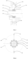
- FIG. 1 it illustrates schematically in general terms the structure of one embodiment of a sealing system for a magnetic levitating centrifugal compressor.
- Said magnetic levitating centrifugal compressor includes a motor cavity (not shown) and a motor shaft 100.
- Said motor shaft 100 is located within said motor cavity and supported in rotation by a magnetic levitating bearing assembly.
- An end of said motor shaft 100 extends out from said motor cavity and is mounted with an impeller (not shown) and a touchdown bearing 110.
- Said magnetic levitating bearing assembly may include: a radial magnetic levitating bearing (not shown), an axially magnetic levitating bearing (not shown). There is a radial clearance between said touchdown bearing 110 and the motor shaft 100.
- the radial clearance is smaller than the radial clearance between the stator portion and the rotor stack of said radial magnetic levitating bearing (the rotor stack of said radial magnetic levitating bearing is fixedly mounted on the outer side of the motor shaft), thus avoiding collision between the rotor stack and the stator portion of said radial magnetic levitating bearing in the event of a stoppage or a sudden power failure of said magnetic levitating centrifugal compressor.
- Said touchdown bearing 110 may be in the form of a ball bearing.
- said sealing system comprises: a seal 120, a first magnet 130 and a second magnet 140.
- the seal 120 for example in the form of a labyrinth seal structure with teeth, is sleeved on the outer side of said motor shaft 100 and is disposed between said impeller and said motor cavity so as to reduce the flow of fluid from said impeller to said motor cavity.
- said first magnet 130 is fixed at the outer surface of said motor shaft 100.
- Said second magnet 140 is fixed at a side of said seal 120 facing said motor shaft 100.
- Said first magnet 130 and said second magnet 140 form a radial repulsive force in the radial direction of said motor shaft 100 (as shown by the arrow in FIG. 2 ), e.g., the magnetic poles of the opposite sides of said first magnet 130 and said second magnet 140 are the same, enabling said seal 120 to be "levitated” on said motor shaft 100, thus preventing said seal 120, and in particular its toothed structure, from colliding with said motor shaft 100.
- the term “levitated” here refers to a state in which the seal 120 maintains a relatively stable interval with respect to the motor shaft 100.
- the seal 120 and the motor shaft 100 maintain a concentric interval. Since said seal 120 is designed in a follow-up structure, i.e. said seal 120 can be levitated up and down with said motor shaft 100, the radial clearance between said seal and said motor shaft may be designed to be as small as possible, so as to further reduce the gas leakage from the back side of said impeller near said motor cavity.
- said motor shaft 100 When said magnetic levitating centrifugal compressor is in normal operation, said motor shaft 100 is levitated and running at high speed, while said seal 120 remains concentrically arranged with said motor shaft 100 under the action of radial repulsive force, as shown in FIG. 1 .
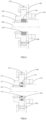
- said motor shaft 100 falls due to gravity and comes into contact with said touchdown bearing 110, as shown in FIG. 3 .
- said seal 120 falls with said motor shaft 100 under the mutual repulsive force of said first magnet 130 and said second magnet 140, at which time the radial clearance between said seal 120 and said housing 160 at the top becomes larger and the radial clearance between said seal 120 and housing 160 at the bottom becomes smaller, while no contact occurs between said seal 120 and said motor shaft 100.
- an extension spring 150 is provided at the top of said seal 120.
- One end of said extension spring 150 rests against said seal 120 and the other end of said extension spring 150 rests against the housing 160.
- Said housing 160 is fixedly connected to the shell (not shown) of said motor cavity.
- a compression spring is provided at the bottom of said seal. One end of said compression spring rests against said seal and the other end of said compression spring rests against said housing. Said housing is fixedly connected to the shell of said motor cavity.
- said motor shaft 100 is provided with a sleeve 170, said sleeve 170 is for example tightly fitted to said motor shaft 100, and said first magnet 130 is fixed to said sleeve 170 in an inserted manner, thereby preventing said first magnets from flying out due to centrifugal force when the motor shaft is rotating.
- said plurality of first magnets are fixed at the outer surface of said motor shaft by means of carbon fiber tape in a winding manner.
- said sealing system further comprises an anti-rotation pin 180, wherein said anti-rotation pin 180 is inserted between said seal 120 and said housing 160 to prevent said seal 120 from rotating relative to said housing 160, i.e. said seal 120 can only be levitated up and down with said motor shaft 100. Further, there are a plurality of said anti-rotation pins 180 and said plurality of anti-rotation pins 180 are arranged at equal intervals in the circumferential direction of said seal 120.
- the volute cavity in which said impeller is located is a high pressure area and said motor cavity is a low pressure area, so that the pressure on the side of said seal 120 near said impeller is always greater than the pressure on the side of said seal 120 near said motor cavity, causing friction due to the side of said seal 120 (on the right in the figure) abutting against said housing 160, as shown in the circled portion of FIG. 1 .
- the wear-resistant coating may be provided on the fitting surfaces between said seal 120 and said housing 160.
- said seal will not be levitated when said motor shaft moves slightly, but only be moved with the motor shaft when the radial movement of the motor shaft exceeds a certain value, i.e. when the repulsive force on said seal exceeds the frictional force, and the certain value of radial movement must not exceed the sealing gap between said seal and said motor shaft surface.
- said first magnet 130 and said second magnet 140 are radially magnetizing permanent magnets, as shown in FIGS. 1 and 3 . By this time, the direction of the repulsive force between the first magnet 130 and the second magnet 140 is along the radial direction of the motor shaft 100.
- said first magnet 130 and said second magnet 140 are axially magnetizing permanent magnets, as shown in FIG. 4 . By this time, the direction of the repulsive force between the first magnet 130 and the second magnet 140 is along the axial direction of the motor shaft 100.
- the repulsive force in the axial direction needs to be converted into a repulsive force in the radial direction by the magnetic conductive ring 190 made of magnetic conductive metal.
- the axially magnetizing permanent magnet has a simpler manufacturing process and lower cost.
- a sealing system for magnetic levitating centrifugal compressor may also be provided.
- Said magnetic levitating centrifugal compressor may be of a back-to-back two-stage compression design.
- said magnetic levitating centrifugal compressor may comprise a motor cavity and a motor shaft located in said motor cavity, a first impeller and a second impeller, wherein said first impeller constitutes a low pressure stage of compression and said second impeller constitutes a high pressure stage of compression, said second impeller, i.e., the impeller of the second stage, being typically smaller than said first impeller, i.e., the impeller of the first stage, wherein the inlet of the impeller of the second stage is the outlet of the impeller of the first stage.
- Said motor shaft is located in said motor cavity and is supported by a magnetic levitating bearing assembly during rotation.
- Said motor shaft has a first end and a second end extending out from said motor cavity.
- Said first end of said motor shaft is mounted with a first impeller and a first touchdown bearing
- said second end of said motor shaft is mounted with a second impeller and a second touchdown bearing.
- both of the first end and the second end of the motor shaft are provided with the sealing construction as shown in FIG. 1 , 3 or 4 .
- said sealing system comprises: a first seal, a second seal, a first magnet assembly, and a second magnet assembly.
- Said first seal is sleeved on the outer side of said motor shaft 100 and is located between said first impeller and said motor cavity, thereby reducing the flow of fluid from said first impeller to said motor cavity.
- Said second seal is sleeved on the outside of said motor shaft and is located between said second impeller and said motor cavity, thereby reducing the flow of fluid from said second impeller to said motor cavity.
- Said first magnet assembly includes a first magnet 130 and a second magnet 140, said first magnet 130 is fixed at the outer surface of said motor shaft 100 and said second magnet 140 is fixed at a side of said first seal facing said motor shaft 100.
- Said second magnet assembly includes a third magnet and a fourth magnet, said third magnet is fixed at the outer surface of said motor shaft and said fourth magnet is fixed at a side of said second seal facing said motor shaft.
- Said first magnet and said second magnet form a repulsive force in the radial direction of said motor shaft and keep said first seal and said motor shaft in a concentric levitation
- said third magnet and said fourth magnet form a repulsive force in the radial direction of said motor shaft and keep said second seal and said motor shaft in a concentric levitation.
- the sealing system for magnetic levitating centrifugal compressor is of a follow-up type construction, using the radial repulsive force between the magnets to keep the seal and the motor shaft in a concentric arrangement and to enable said seal to be levitated on said motor shaft.
- the radial clearance between the seal and the motor shaft becomes as small as possible without the use of additional tooling or special designs, and the gas leakage from the back side of said impeller near said motor cavity is further reduced.
- a magnetic levitating centrifugal compressor which itself is provided with a sealing system as described according to various embodiments.
- a refrigeration system configured with said magnetic levitating centrifugal compressor is provided.
- Said refrigeration system may comprise a cooling tower, a cooling water unit and a pumping unit, etc. connected by piping, wherein said cooling water unit comprises a magnetic levitating centrifugal compressor, a condenser, a throttling device and an evaporator, etc.
Landscapes
- Engineering & Computer Science (AREA)
- General Engineering & Computer Science (AREA)
- Mechanical Engineering (AREA)
- Physics & Mathematics (AREA)
- Electromagnetism (AREA)
- Structures Of Non-Positive Displacement Pumps (AREA)
Abstract
Description
- The present invention relates to the field of refrigeration technology, in particular to a sealing system for a magnetic levitating centrifugal compressor, to a magnetic levitating centrifugal compressor provided with said sealing system, and to a refrigeration system configured with said magnetic levitating centrifugal compressor.
- Currently, centrifugal compressors gradually adopt oil-free lubrication technology to replace the former oil circuit lubrication, thus eliminating the management of the lubricating oil system, such as oil circuit maintenance, oil return management and maintenance of the oil circuit system. On the other hand, oil-free lubrication also represents higher operating efficiency of compressor and higher operating efficiency of refrigeration system, lower vibration and noise, stable operation and much lower cost, cleaner and better customer experience.
- Magnetic levitating bearings are an important way and means to solve the problem of oil-free lubrication of centrifugal compressors. A centrifugal compressor supported by magnetic levitating bearings consists of shell, volute, impeller, magnetic levitating bearings and high-speed motor and other parts. In the working process, the high-speed motor is supported by the magnetic levitating bearings at the left and right ends, with low rotary resistance and high rotational speed. In this type of bearing mechanism, there is often a touchdown bearing, which is designed to prevent damage of the magnetic levitating bearing part resulting from the collision of the magnetic levitating bearings with the motor shaft when the magnetic levitating bearings fail. Therefore, the radial clearance between the touchdown bearing and the motor shaft is typically smaller than the radial clearance between the magnetic levitating bearings and the motor shaft. For example, the radial clearance between the touchdown bearing and the motor shaft may be half of the radial clearance between the magnetic levitating bearings and the motor shaft. In addition, in order to prevent airflow from the impeller side entering into the motor cavity, a seal is provided between the impeller and the motor cavity, where said seal is typically a fixed labyrinth seal structure with teeth and fixed to the shell of the motor cavity. In order to avoid tooth damage due to collision between said motor shaft and said seal, the radial clearance between said seal and said motor shaft is designed to be relatively large, generally more than twice the touchdown bearing clearance. Thus, the sealing effect of said seal is relatively poor, and the amount of gas leaking from the impeller side is high, resulting in lower efficiency of the magnetic levitating centrifugal compressor.
- According to a first aspect, there is provided a sealing system for a magnetic levitating centrifugal compressor. This system, or at least embodiments thereof, may effectively solve the above-mentioned problems and the problems of other aspects that exist in the prior art. Said magnetic levitating centrifugal compressor comprises a motor cavity and a motor shaft disposed within said motor cavity. An end of said motor shaft extends out from said motor cavity and is mounted with an impeller. Said sealing system comprises: a seal, wherein said seal is sleeved on the outer side of said motor shaft and is disposed between said impeller and said motor cavity, for reducing the flow of fluid from said impeller to said motor cavity;
- a first magnet, wherein said first magnet is fixed at an outer surface of said motor shaft; and
- a second magnet, wherein said second magnet is fixed at a side of said seal facing said motor shaft;
- Optionally, a tension spring is provided on top of said seal for resisting the gravity of said seal. One end of said tension spring may rest against said seal and the other end of said tension spring may rest against a housing. Said housing may be fixedly connected to the shell of said motor cavity.
- Optionally, a compression spring is provided at the bottom of said seal for resisting the gravity of said seal. One end of said compression spring may rest against said seal and the other end of said compression spring may rest against a housing. Said housing may be fixedly connected to the shell of said motor cavity.
- Optionally, there are a plurality of said first magnets and a plurality of said second magnets, wherein the plurality of said first magnets are arranged at an outer surface of said motor shaft at equal intervals along the radial direction of said motor shaft, and the plurality of said second magnets are arranged at equal intervals on a side of said seal facing said motor shaft.
- Optionally, said motor shaft is provided with a sleeve, and said first magnets are fixed to said sleeve in an inserted manner.
- Optionally, the plurality of said first magnets are fixed at the outer surface of said motor shaft by means of a carbon fiber tape in a winding manner.
- Optionally, said sealing system further comprises an anti-rotation pin, wherein said anti-rotation pin is inserted between said seal and said housing for preventing said seal from rotating relative to said housing.
- Optionally, there are a plurality of said anti-rotation pins, and the plurality of said anti-rotation pins are arranged at equal intervals in the circumferential direction of said seal.
- Optionally, a side of said seal fits against said housing, and the fitting surfaces between said seal and said housing are provided with a wear resistant coating.
- Optionally, said first magnet and said second magnet are radially magnetizing permanent magnets; or said first magnet and said second magnet are axially magnetizing permanent magnets.
- According to a second aspect, there is provided a magnetic levitating centrifugal compressor, wherein said magnetic levitating centrifugal compressor is provided with a sealing system as described above, with any of the optional features.
- According to a third aspect, there is provided a refrigeration system, wherein said refrigeration system is configured with a magnetic levitating centrifugal compressor as described above, with any of the optional features.
- According to a fourth aspect, there is provided a sealing system for a magnetic levitating centrifugal compressor, wherein said magnetic levitating centrifugal compressor comprises a motor cavity and a motor shaft disposed within said motor cavity, said motor shaft has a first end and a second end extending out from said motor cavity, said first end of said motor shaft is mounted with a first impeller, and said second end of said motor shaft is mounted with a second impeller. Said sealing system comprises:
- a first seal, wherein said first seal is sleeved on the outer side of said motor shaft and is disposed between said first impeller and said motor cavity, for reducing the flow of fluid from said first impeller to said motor cavity;
- a second seal, wherein said second seal is sleeved on the outer side of said motor shaft and is disposed between said second impeller and motor cavity, for reducing the flow of fluid from said second impeller to said motor cavity;
- a first magnet assembly, wherein said first magnet assembly comprises a first magnet and a second magnet, said first magnet is fixed at an outer surface of said motor shaft and said second magnet is fixed at a side of said first seal facing said motor shaft; and
- a second magnet assembly, wherein said second magnet assembly comprises a third magnet and a fourth magnet, said third magnet is fixed at an outer surface of said motor shaft and said fourth magnet is fixed at a side of said second seal facing said motor shaft,
- According to a fifth aspect, there is provided a magnetic levitating centrifugal compressor, wherein said magnetic levitating centrifugal compressor is provided with a sealing system as described above.
- According to a sixth aspect, there is provided a refrigeration system, wherein said refrigeration system is configured with a magnetic levitating centrifugal compressor as described above.
- It can be understood that the sealing system for a magnetic levitating centrifugal compressor may be of a follow-up construction, using mutually repulsive magnetic forces to enable the seal to be levitated relative to (in relation to) the motor shaft. As a result, the radial clearance between the seal of said sealing system and the motor shaft may be designed to be as small as possible without the use of additional tooling or special designs, further reducing the gas leakage from the impeller side.
- Certain exemplary embodiments will now be described in greater detail by way of example only and with reference to the accompanying drawings in which:
-
FIG. 1 illustrates a schematic cross-sectional view of a sealing system for a magnetic levitating centrifugal compressor; -
FIG. 2 illustrates a schematic longitudinal sectional view of the sealing system for a magnetic levitating centrifugal compressor ofFIG. 1 ; -
FIG. 3 illustrates a schematic cross-sectional view of the sealing system for a magnetic levitating centrifugal compressor ofFIG. 1 with the motor shaft falling onto the touchdown bearing; and -
FIG. 4 illustrates a schematic cross-sectional view of a sealing system for a magnetic levitating centrifugal compressor in the case of using an axially magnetizing permanent magnet. - Several embodiments will be described in detail below in connection with the accompanying drawings. It should be noted that the orientation terms such as up, down, left, right, front, back, inside, outside, top, bottom, etc., mentioned or may mentioned in this description are defined relative to the construction shown in each of the accompanying drawings, and they are relative concepts, and therefore may change accordingly depending on the different location and different state of use in which they are located. Therefore, these or other orientation terms should not be interpreted as restrictive terms.
- As shown in
FIG. 1 , it illustrates schematically in general terms the structure of one embodiment of a sealing system for a magnetic levitating centrifugal compressor. Said magnetic levitating centrifugal compressor includes a motor cavity (not shown) and amotor shaft 100. Saidmotor shaft 100 is located within said motor cavity and supported in rotation by a magnetic levitating bearing assembly. An end of saidmotor shaft 100 extends out from said motor cavity and is mounted with an impeller (not shown) and a touchdown bearing 110. Said magnetic levitating bearing assembly may include: a radial magnetic levitating bearing (not shown), an axially magnetic levitating bearing (not shown). There is a radial clearance between said touchdown bearing 110 and themotor shaft 100. The radial clearance is smaller than the radial clearance between the stator portion and the rotor stack of said radial magnetic levitating bearing (the rotor stack of said radial magnetic levitating bearing is fixedly mounted on the outer side of the motor shaft), thus avoiding collision between the rotor stack and the stator portion of said radial magnetic levitating bearing in the event of a stoppage or a sudden power failure of said magnetic levitating centrifugal compressor. Said touchdown bearing 110 may be in the form of a ball bearing. As can be clearly seen fromFIGS 1 and 2 , said sealing system comprises: aseal 120, afirst magnet 130 and asecond magnet 140. Theseal 120, for example in the form of a labyrinth seal structure with teeth, is sleeved on the outer side of saidmotor shaft 100 and is disposed between said impeller and said motor cavity so as to reduce the flow of fluid from said impeller to said motor cavity. In general, there is a radial clearance between saidseal 120 and themotor shaft 100. Said radial clearance is greater than the radial clearance existing between said touchdown bearing 110 and themotor shaft 100, so as to prevent tooth damage of the labyrinth seal structure due to collision of said seal with the motor shaft in case of stoppage or sudden power failure of said magnetic levitating centrifugal compressor. - In the above embodiment of the sealing system for magnetic levitating centrifugal compressor, said
first magnet 130 is fixed at the outer surface of saidmotor shaft 100. Saidsecond magnet 140 is fixed at a side of saidseal 120 facing saidmotor shaft 100. Saidfirst magnet 130 and saidsecond magnet 140 form a radial repulsive force in the radial direction of said motor shaft 100 (as shown by the arrow inFIG. 2 ), e.g., the magnetic poles of the opposite sides of saidfirst magnet 130 and saidsecond magnet 140 are the same, enabling saidseal 120 to be "levitated" on saidmotor shaft 100, thus preventing saidseal 120, and in particular its toothed structure, from colliding with saidmotor shaft 100. The term "levitated" here refers to a state in which theseal 120 maintains a relatively stable interval with respect to themotor shaft 100. Preferably, theseal 120 and themotor shaft 100 maintain a concentric interval. Since saidseal 120 is designed in a follow-up structure, i.e. saidseal 120 can be levitated up and down with saidmotor shaft 100, the radial clearance between said seal and said motor shaft may be designed to be as small as possible, so as to further reduce the gas leakage from the back side of said impeller near said motor cavity. - When said magnetic levitating centrifugal compressor is in normal operation, said
motor shaft 100 is levitated and running at high speed, while saidseal 120 remains concentrically arranged with saidmotor shaft 100 under the action of radial repulsive force, as shown inFIG. 1 . When said magnetic levitating centrifugal compressor stops working or when there is a sudden power failure, saidmotor shaft 100 falls due to gravity and comes into contact with said touchdown bearing 110, as shown inFIG. 3 . At this time, saidseal 120 falls with saidmotor shaft 100 under the mutual repulsive force of saidfirst magnet 130 and saidsecond magnet 140, at which time the radial clearance between saidseal 120 and saidhousing 160 at the top becomes larger and the radial clearance between saidseal 120 andhousing 160 at the bottom becomes smaller, while no contact occurs between saidseal 120 and saidmotor shaft 100. - In order to be able to partially or even fully counteract the gravity of said
seal 120 so as to keep saidseal 120 and saidmotor shaft 100 as concentric as possible under the action of the repulsive force of the magnets, anextension spring 150 is provided at the top of saidseal 120. One end of saidextension spring 150 rests against saidseal 120 and the other end of saidextension spring 150 rests against thehousing 160. Saidhousing 160 is fixedly connected to the shell (not shown) of said motor cavity. Alternatively, a compression spring is provided at the bottom of said seal. One end of said compression spring rests against said seal and the other end of said compression spring rests against said housing. Said housing is fixedly connected to the shell of said motor cavity. - In conjunction with the above embodiment, in other preferred embodiments, there are a plurality of said
first magnet 130 and saidsecond magnet 140, wherein the plurality of saidfirst magnets 130 are arranged at an outer surface of saidmotor shaft 100 at equal intervals along the radial direction of saidmotor shaft 100, and the plurality of saidsecond magnets 140 are arranged at equal intervals on a side of saidseal 120 facing saidmotor shaft 100, as shown inFIG. 2 . Further, saidmotor shaft 100 is provided with asleeve 170, saidsleeve 170 is for example tightly fitted to saidmotor shaft 100, and saidfirst magnet 130 is fixed to saidsleeve 170 in an inserted manner, thereby preventing said first magnets from flying out due to centrifugal force when the motor shaft is rotating. As an alternative, said plurality of first magnets are fixed at the outer surface of said motor shaft by means of carbon fiber tape in a winding manner. - With continued reference to
FIG. 2 , said sealing system further comprises ananti-rotation pin 180, wherein saidanti-rotation pin 180 is inserted between saidseal 120 and saidhousing 160 to prevent saidseal 120 from rotating relative to saidhousing 160, i.e. saidseal 120 can only be levitated up and down with saidmotor shaft 100. Further, there are a plurality of said anti-rotation pins 180 and said plurality ofanti-rotation pins 180 are arranged at equal intervals in the circumferential direction of saidseal 120. - It will be readily understood by those skilled in the art that typically the volute cavity in which said impeller is located is a high pressure area and said motor cavity is a low pressure area, so that the pressure on the side of said
seal 120 near said impeller is always greater than the pressure on the side of saidseal 120 near said motor cavity, causing friction due to the side of said seal 120 (on the right in the figure) abutting against saidhousing 160, as shown in the circled portion ofFIG. 1 . Thus, the wear-resistant coating may be provided on the fitting surfaces between saidseal 120 and saidhousing 160. On the other hand, due to the friction, said seal will not be levitated when said motor shaft moves slightly, but only be moved with the motor shaft when the radial movement of the motor shaft exceeds a certain value, i.e. when the repulsive force on said seal exceeds the frictional force, and the certain value of radial movement must not exceed the sealing gap between said seal and said motor shaft surface. - As an example, said
first magnet 130 and saidsecond magnet 140 are radially magnetizing permanent magnets, as shown inFIGS. 1 and3 . By this time, the direction of the repulsive force between thefirst magnet 130 and thesecond magnet 140 is along the radial direction of themotor shaft 100. As an alternative, saidfirst magnet 130 and saidsecond magnet 140 are axially magnetizing permanent magnets, as shown inFIG. 4 . By this time, the direction of the repulsive force between thefirst magnet 130 and thesecond magnet 140 is along the axial direction of themotor shaft 100. In order to enable theseal 120 to levitate relative to themotor shaft 100, the repulsive force in the axial direction needs to be converted into a repulsive force in the radial direction by the magneticconductive ring 190 made of magnetic conductive metal. Compared with the radially magnetizing permanent magnet, the axially magnetizing permanent magnet has a simpler manufacturing process and lower cost. - A sealing system for magnetic levitating centrifugal compressor may also be provided. Said magnetic levitating centrifugal compressor may be of a back-to-back two-stage compression design. Specifically, said magnetic levitating centrifugal compressor may comprise a motor cavity and a motor shaft located in said motor cavity, a first impeller and a second impeller, wherein said first impeller constitutes a low pressure stage of compression and said second impeller constitutes a high pressure stage of compression, said second impeller, i.e., the impeller of the second stage, being typically smaller than said first impeller, i.e., the impeller of the first stage, wherein the inlet of the impeller of the second stage is the outlet of the impeller of the first stage. Said motor shaft is located in said motor cavity and is supported by a magnetic levitating bearing assembly during rotation. Said motor shaft has a first end and a second end extending out from said motor cavity. Said first end of said motor shaft is mounted with a first impeller and a first touchdown bearing, and said second end of said motor shaft is mounted with a second impeller and a second touchdown bearing.
- In the above embodiment of back-to-back two-stage compression, both of the first end and the second end of the motor shaft are provided with the sealing construction as shown in
FIG. 1 ,3 or 4 . Specifically, said sealing system comprises: a first seal, a second seal, a first magnet assembly, and a second magnet assembly. Said first seal is sleeved on the outer side of saidmotor shaft 100 and is located between said first impeller and said motor cavity, thereby reducing the flow of fluid from said first impeller to said motor cavity. Said second seal is sleeved on the outside of said motor shaft and is located between said second impeller and said motor cavity, thereby reducing the flow of fluid from said second impeller to said motor cavity. Said first magnet assembly includes afirst magnet 130 and asecond magnet 140, saidfirst magnet 130 is fixed at the outer surface of saidmotor shaft 100 and saidsecond magnet 140 is fixed at a side of said first seal facing saidmotor shaft 100. Said second magnet assembly includes a third magnet and a fourth magnet, said third magnet is fixed at the outer surface of said motor shaft and said fourth magnet is fixed at a side of said second seal facing said motor shaft. Said first magnet and said second magnet form a repulsive force in the radial direction of said motor shaft and keep said first seal and said motor shaft in a concentric levitation, and said third magnet and said fourth magnet form a repulsive force in the radial direction of said motor shaft and keep said second seal and said motor shaft in a concentric levitation. - In summary, the sealing system for magnetic levitating centrifugal compressor is of a follow-up type construction, using the radial repulsive force between the magnets to keep the seal and the motor shaft in a concentric arrangement and to enable said seal to be levitated on said motor shaft. In this way, the radial clearance between the seal and the motor shaft becomes as small as possible without the use of additional tooling or special designs, and the gas leakage from the back side of said impeller near said motor cavity is further reduced.
- In addition, a magnetic levitating centrifugal compressor is provided, which itself is provided with a sealing system as described according to various embodiments. In addition, a refrigeration system configured with said magnetic levitating centrifugal compressor is provided. Said refrigeration system may comprise a cooling tower, a cooling water unit and a pumping unit, etc. connected by piping, wherein said cooling water unit comprises a magnetic levitating centrifugal compressor, a condenser, a throttling device and an evaporator, etc. As pointed out in the above, by providing the above-mentioned magnetic levitating centrifugal compressor, the air tightness can be effectively improved without additional manufacturing cost. Thus, the efficiency of the magnetic levitating centrifugal compressor is further improved, and therefore it is recommended herein to use the above-mentioned magnetic levitating centrifugal compressor in all kinds of refrigeration systems.
- The specific embodiments described above are intended only to describe more clearly the principle of the present invention, which is made easier to understand by clearly illustrating or describing the individual components. Without departing from the scope of the claims, the person skilled in the art may easily make various modifications or variations to the present invention. Therefore, it should be understood that these modifications or variations should be included within the scope of the claims.
Claims (15)
- A sealing system for a magnetic levitating centrifugal compressor, wherein said magnetic levitating centrifugal compressor comprises a motor cavity and a motor shaft (100) disposed within said motor cavity, and an end of said motor shaft (100) extends out from said motor cavity and is mounted with an impeller, characterized in that, said sealing system comprises:a seal (120), wherein said seal (120) is sleeved on the outer side of said motor shaft (100) and is disposed between said impeller and said motor cavity, for reducing the flow of fluid from said impeller to said motor cavity;a first magnet (130), wherein said first magnet (130) is fixed at an outer surface of said motor shaft (100); anda second magnet (140), wherein said second magnet (140) is fixed at a side of said seal (120) facing said motor shaft (100),wherein said first magnet (130) and said second magnet (140) form a radial repulsive force in the radial direction of said motor shaft (100), so that said seal (120) can be levitated in relation to said motor shaft (100).
- The sealing system according to claim 1, characterized in that, a tension spring (150) is provided on top of said seal (120) for resisting the gravity of said seal (120), wherein one end of said tension spring (150) rests against said seal (120) and the other end of said tension spring (150) rests against a housing (160), and said housing (160) is fixedly connected to the shell of said motor cavity.
- The sealing system according to claim 1, characterized in that, a compression spring is provided at the bottom of said seal (120) for resisting the gravity of said seal (120), wherein one end of said compression spring rests against said seal (120) and the other end of said compression spring rests against a housing (160), and said housing (160) is fixedly connected to the shell of said motor cavity.
- The sealing system according to claim 2 or 3, characterized in that, there are a plurality of said first magnets (130) and a plurality of said second magnets (140), wherein the plurality of said first magnets (130) are arranged at an outer surface of said motor shaft (100) at equal intervals along the radial direction of said motor shaft (100), and the plurality of said second magnets (140) are arranged at equal intervals on a side of said seal (120) facing said motor shaft (100).
- The sealing system according to claim 4, characterized in that, said motor shaft (100) is provided with a sleeve (170), and said first magnets (130) are fixed to said sleeve (170) in an inserted manner.
- The sealing system according to claim 4, characterized in that, the plurality of said first magnets (130) are fixed at the outer surface of said motor shaft (100) by means of a carbon fiber tape in a winding manner.
- The sealing system according to claim 2 or 3, characterized in that, said sealing system further comprises an anti-rotation pin (180), wherein said anti-rotation pin (180) is inserted between said seal (120) and said housing (160) for preventing said seal (120) from rotating relative to said housing (160).
- The sealing system according to claim 7, characterized in that, there are a plurality of said anti-rotation pins (180), and the plurality of said anti-rotation pins (180) are arranged at equal intervals in the circumferential direction of said seal (120).
- The sealing system according to claim 2 or 3, characterized in that, a side of said seal (120) fits against said housing (160), and the fitting surfaces between said seal (120) and said housing (160) are provided with a wear resistant coating.
- The sealing system according to claim 2 or 3, characterized in that, said first magnet (130) and said second magnet (140) are radially magnetizing permanent magnets; or in that said first magnet (130) and said second magnet (140) are axially magnetizing permanent magnets.
- A magnetic levitating centrifugal compressor, characterized in that, said magnetic levitating centrifugal compressor is provided with the sealing system according to any one of claims 1-10.
- A refrigeration system, characterized in that, said refrigeration system is configured with the magnetic levitating centrifugal compressor according to claim 11.
- A sealing system for a magnetic levitating centrifugal compressor, wherein said magnetic levitating centrifugal compressor comprises a motor cavity and a motor shaft (100) disposed within said motor cavity, said motor shaft (100) has a first end and a second end extending out from said motor cavity, said first end of said motor shaft (100) is mounted with a first impeller, and said second end of said motor shaft (100) is mounted with a second impeller, characterized in that, said sealing system comprises:a first seal (120), wherein said first seal (120) is sleeved on the outer side of said motor shaft (100) and is disposed between said first impeller and said motor cavity, for reducing the flow of fluid from said first impeller to said motor cavity;a second seal (120), wherein said second seal (120) is sleeved on the outer side of said motor shaft (100) and is disposed between said second impeller and said motor cavity, for reducing the flow of fluid from said second impeller to said motor cavity;a first magnet assembly, wherein said first magnet assembly comprises a first magnet (130) and a second magnet (140), said first magnet (130) is fixed at an outer surface of said motor shaft (100) and said second magnet (140) is fixed at a side of said first seal (120) facing said motor shaft (100); anda second magnet assembly, wherein said second magnet assembly comprises a third magnet and a fourth magnet, said third magnet is fixed at an outer surface of said motor shaft (100) and said fourth magnet is fixed at a side of said second seal (120) facing said motor shaft (100),wherein said first magnet (130) and said second magnet (140) form a repulsive force in a radial direction of said motor shaft (100) to keep said first seal (120) and said motor shaft (100) in a concentric levitation, and wherein said third magnet and said fourth magnet form a repulsive force in a radial direction of said motor shaft (100) to keep said second seal (120) and said motor shaft (100) in a concentric levitation.
- A magnetic levitating centrifugal compressor, characterized in that, said magnetic levitating centrifugal compressor is provided with the sealing system according to claim 13.
- A refrigeration system, characterized in that, said refrigeration system is configured with the magnetic levitating centrifugal compressor according to claim 14.
Applications Claiming Priority (1)
| Application Number | Priority Date | Filing Date | Title |
|---|---|---|---|
| CN202210047178.6A CN116480619A (en) | 2022-01-17 | 2022-01-17 | Sealing system for magnetic levitation centrifugal compressor and magnetic levitation centrifugal compressor |
Publications (1)
| Publication Number | Publication Date |
|---|---|
| EP4212735A1 true EP4212735A1 (en) | 2023-07-19 |
Family
ID=84389331
Family Applications (1)
| Application Number | Title | Priority Date | Filing Date |
|---|---|---|---|
| EP22211515.6A Pending EP4212735A1 (en) | 2022-01-17 | 2022-12-05 | Sealing system for a magnetic levitating centrifugal compressor and a magnetic levitating centrifugal compressor |
Country Status (3)
| Country | Link |
|---|---|
| US (1) | US20230228275A1 (en) |
| EP (1) | EP4212735A1 (en) |
| CN (1) | CN116480619A (en) |
Citations (5)
| Publication number | Priority date | Publication date | Assignee | Title |
|---|---|---|---|---|
| US5137286A (en) * | 1991-08-23 | 1992-08-11 | General Electric Company | Permanent magnet floating shaft seal |
| US6220602B1 (en) * | 1998-04-17 | 2001-04-24 | Rolls-Royce Plc | Seal arrangement |
| US20040126226A1 (en) * | 2002-12-26 | 2004-07-01 | Addis Mark E. | Seal |
| US20090015012A1 (en) * | 2007-07-14 | 2009-01-15 | Andreas Metzler | Axial in-line turbomachine |
| WO2021230909A1 (en) * | 2020-05-11 | 2021-11-18 | Danfoss A/S | Floating ring seal for refrigerant compressor |
-
2022
- 2022-01-17 CN CN202210047178.6A patent/CN116480619A/en active Pending
- 2022-12-05 EP EP22211515.6A patent/EP4212735A1/en active Pending
-
2023
- 2023-01-12 US US18/153,789 patent/US20230228275A1/en not_active Abandoned
Patent Citations (5)
| Publication number | Priority date | Publication date | Assignee | Title |
|---|---|---|---|---|
| US5137286A (en) * | 1991-08-23 | 1992-08-11 | General Electric Company | Permanent magnet floating shaft seal |
| US6220602B1 (en) * | 1998-04-17 | 2001-04-24 | Rolls-Royce Plc | Seal arrangement |
| US20040126226A1 (en) * | 2002-12-26 | 2004-07-01 | Addis Mark E. | Seal |
| US20090015012A1 (en) * | 2007-07-14 | 2009-01-15 | Andreas Metzler | Axial in-line turbomachine |
| WO2021230909A1 (en) * | 2020-05-11 | 2021-11-18 | Danfoss A/S | Floating ring seal for refrigerant compressor |
Also Published As
| Publication number | Publication date |
|---|---|
| CN116480619A (en) | 2023-07-25 |
| US20230228275A1 (en) | 2023-07-20 |
Similar Documents
| Publication | Publication Date | Title |
|---|---|---|
| US11306726B2 (en) | Foil bearing assembly and compressor including same | |
| US20090028731A1 (en) | Ball bearing and a vacuum pump that is equipped with a bearing of this type | |
| KR100999015B1 (en) | Turbo machine | |
| US11686341B2 (en) | Foil bearing assembly including segmented inner foil assembly and compressor including same | |
| CN111365258A (en) | Compressor and air conditioning unit | |
| US9212665B2 (en) | Planetary-type auxiliary bearing for a hydrostatic primary bearing | |
| US11280220B2 (en) | Turbomachine with axial force adjustment at a bearing | |
| KR102888624B1 (en) | Turbomachinery With Foil Air Bearings | |
| US20060183074A1 (en) | Dental handpiece with air-foil bearings | |
| CN211398276U (en) | Rotor subassembly, compressor and air conditioning equipment | |
| CN213754230U (en) | Protection structure of magnetic suspension motor, magnetic suspension system and turbine machinery | |
| JP7807531B2 (en) | Magnetic levitation pump, refrigeration equipment having a magnetic levitation pump, and outdoor unit of an air conditioner | |
| US20230228275A1 (en) | Sealing system for magnetic levitating centrifugal compressor and magnetic levitating centrifugal compressor | |
| US20250361872A1 (en) | Sealing system for magnetic levitating centrifugal compressor and magnetic levitating centrifugal compressor | |
| EP4403786B1 (en) | Gas bearing for centrifugal compressor, centrifugal compressor and refrigeration system | |
| EP3892875A1 (en) | Flushing of a touchdown bearing | |
| CN112564401A (en) | Protection structure of magnetic suspension motor, magnetic suspension system and turbine machinery | |
| KR100723040B1 (en) | Bearing assembly for high speed rotor | |
| CN116658458A (en) | A double-motor impeller structure | |
| KR100749828B1 (en) | Radial Foil Bearings with Seal Function | |
| US20180119702A1 (en) | Air compressor or water pump | |
| US5833374A (en) | Rotatable assembly for supporting of the rotor of a vacuum pump | |
| JP7534466B2 (en) | Vacuum pump with improved suction capacity of Holweck pump stage | |
| CN222785856U (en) | Shaft extension low-play motor | |
| EP0806571A2 (en) | A rotatable assembly for supporting the rotor of a vacuum pump |
Legal Events
| Date | Code | Title | Description |
|---|---|---|---|
| PUAI | Public reference made under article 153(3) epc to a published international application that has entered the european phase |
Free format text: ORIGINAL CODE: 0009012 |
|
| STAA | Information on the status of an ep patent application or granted ep patent |
Free format text: STATUS: THE APPLICATION HAS BEEN PUBLISHED |
|
| AK | Designated contracting states |
Kind code of ref document: A1 Designated state(s): AL AT BE BG CH CY CZ DE DK EE ES FI FR GB GR HR HU IE IS IT LI LT LU LV MC ME MK MT NL NO PL PT RO RS SE SI SK SM TR |
|
| STAA | Information on the status of an ep patent application or granted ep patent |
Free format text: STATUS: REQUEST FOR EXAMINATION WAS MADE |
|
| 17P | Request for examination filed |
Effective date: 20240117 |
|
| RBV | Designated contracting states (corrected) |
Designated state(s): AL AT BE BG CH CY CZ DE DK EE ES FI FR GB GR HR HU IE IS IT LI LT LU LV MC ME MK MT NL NO PL PT RO RS SE SI SK SM TR |
|
| GRAP | Despatch of communication of intention to grant a patent |
Free format text: ORIGINAL CODE: EPIDOSNIGR1 |
|
| STAA | Information on the status of an ep patent application or granted ep patent |
Free format text: STATUS: GRANT OF PATENT IS INTENDED |
|
| RIC1 | Information provided on ipc code assigned before grant |
Ipc: F04D 29/10 20060101AFI20250905BHEP Ipc: F16J 15/44 20060101ALI20250905BHEP Ipc: F16J 15/447 20060101ALI20250905BHEP |
|
| INTG | Intention to grant announced |
Effective date: 20251009 |
|
| GRAJ | Information related to disapproval of communication of intention to grant by the applicant or resumption of examination proceedings by the epo deleted |
Free format text: ORIGINAL CODE: EPIDOSDIGR1 |
|
| STAA | Information on the status of an ep patent application or granted ep patent |
Free format text: STATUS: REQUEST FOR EXAMINATION WAS MADE |
|
| INTC | Intention to grant announced (deleted) | ||
| GRAP | Despatch of communication of intention to grant a patent |
Free format text: ORIGINAL CODE: EPIDOSNIGR1 |
|
| STAA | Information on the status of an ep patent application or granted ep patent |
Free format text: STATUS: GRANT OF PATENT IS INTENDED |
|
| INTG | Intention to grant announced |
Effective date: 20260331 |