EP4212723A1 - Safety door assembly - Google Patents
Safety door assembly Download PDFInfo
- Publication number
- EP4212723A1 EP4212723A1 EP22151556.2A EP22151556A EP4212723A1 EP 4212723 A1 EP4212723 A1 EP 4212723A1 EP 22151556 A EP22151556 A EP 22151556A EP 4212723 A1 EP4212723 A1 EP 4212723A1
- Authority
- EP
- European Patent Office
- Prior art keywords
- hoist
- window
- assembly
- sliding door
- barrier
- Prior art date
- Legal status (The legal status is an assumption and is not a legal conclusion. Google has not performed a legal analysis and makes no representation as to the accuracy of the status listed.)
- Granted
Links
Images






Classifications
-
- E—FIXED CONSTRUCTIONS
- E05—LOCKS; KEYS; WINDOW OR DOOR FITTINGS; SAFES
- E05C—BOLTS OR FASTENING DEVICES FOR WINGS, SPECIALLY FOR DOORS OR WINDOWS
- E05C7/00—Fastening devices specially adapted for two wings
- E05C7/04—Fastening devices specially adapted for two wings for wings which abut when closed
- E05C7/06—Fastening devices specially adapted for two wings for wings which abut when closed a fastening device for one wing being actuated or controlled by closing another wing
-
- B—PERFORMING OPERATIONS; TRANSPORTING
- B66—HOISTING; LIFTING; HAULING
- B66C—CRANES; LOAD-ENGAGING ELEMENTS OR DEVICES FOR CRANES, CAPSTANS, WINCHES, OR TACKLES
- B66C23/00—Cranes comprising essentially a beam, boom, or triangular structure acting as a cantilever and mounted for translatory of swinging movements in vertical or horizontal planes or a combination of such movements, e.g. jib-cranes, derricks, tower cranes
- B66C23/18—Cranes comprising essentially a beam, boom, or triangular structure acting as a cantilever and mounted for translatory of swinging movements in vertical or horizontal planes or a combination of such movements, e.g. jib-cranes, derricks, tower cranes specially adapted for use in particular purposes
- B66C23/20—Cranes comprising essentially a beam, boom, or triangular structure acting as a cantilever and mounted for translatory of swinging movements in vertical or horizontal planes or a combination of such movements, e.g. jib-cranes, derricks, tower cranes specially adapted for use in particular purposes with supporting couples provided by walls of buildings or like structures
- B66C23/207—Cranes comprising essentially a beam, boom, or triangular structure acting as a cantilever and mounted for translatory of swinging movements in vertical or horizontal planes or a combination of such movements, e.g. jib-cranes, derricks, tower cranes specially adapted for use in particular purposes with supporting couples provided by walls of buildings or like structures with supporting couples provided by wind turbines
-
- E—FIXED CONSTRUCTIONS
- E06—DOORS, WINDOWS, SHUTTERS, OR ROLLER BLINDS IN GENERAL; LADDERS
- E06B—FIXED OR MOVABLE CLOSURES FOR OPENINGS IN BUILDINGS, VEHICLES, FENCES OR LIKE ENCLOSURES IN GENERAL, e.g. DOORS, WINDOWS, BLINDS, GATES
- E06B11/00—Means for allowing passage through fences, barriers or the like, e.g. stiles
- E06B11/02—Gates; Doors
- E06B11/022—Gates; Doors characterised by the manner of movement
-
- E—FIXED CONSTRUCTIONS
- E04—BUILDING
- E04G—SCAFFOLDING; FORMS; SHUTTERING; BUILDING IMPLEMENTS OR AIDS, OR THEIR USE; HANDLING BUILDING MATERIALS ON THE SITE; REPAIRING, BREAKING-UP OR OTHER WORK ON EXISTING BUILDINGS
- E04G21/00—Preparing, conveying, or working-up building materials or building elements in situ; Other devices or measures for constructional work
- E04G21/32—Safety or protective measures for persons during the construction of buildings
- E04G21/3204—Safety or protective measures for persons during the construction of buildings against falling down
-
- E—FIXED CONSTRUCTIONS
- E04—BUILDING
- E04G—SCAFFOLDING; FORMS; SHUTTERING; BUILDING IMPLEMENTS OR AIDS, OR THEIR USE; HANDLING BUILDING MATERIALS ON THE SITE; REPAIRING, BREAKING-UP OR OTHER WORK ON EXISTING BUILDINGS
- E04G21/00—Preparing, conveying, or working-up building materials or building elements in situ; Other devices or measures for constructional work
- E04G21/32—Safety or protective measures for persons during the construction of buildings
- E04G21/3204—Safety or protective measures for persons during the construction of buildings against falling down
- E04G21/3209—Temporary tunnels specially adapted against falling objects
-
- E—FIXED CONSTRUCTIONS
- E05—LOCKS; KEYS; WINDOW OR DOOR FITTINGS; SAFES
- E05C—BOLTS OR FASTENING DEVICES FOR WINGS, SPECIALLY FOR DOORS OR WINDOWS
- E05C19/00—Other devices specially designed for securing wings, e.g. with suction cups
- E05C19/10—Hook fastenings; Fastenings in which a link engages a fixed hook-like member
-
- E—FIXED CONSTRUCTIONS
- E06—DOORS, WINDOWS, SHUTTERS, OR ROLLER BLINDS IN GENERAL; LADDERS
- E06B—FIXED OR MOVABLE CLOSURES FOR OPENINGS IN BUILDINGS, VEHICLES, FENCES OR LIKE ENCLOSURES IN GENERAL, e.g. DOORS, WINDOWS, BLINDS, GATES
- E06B11/00—Means for allowing passage through fences, barriers or the like, e.g. stiles
- E06B11/02—Gates; Doors
- E06B11/022—Gates; Doors characterised by the manner of movement
- E06B11/023—Gates; Doors characterised by the manner of movement where the gate opens within the plane of the gate
- E06B11/026—Gates; Doors characterised by the manner of movement where the gate opens within the plane of the gate horizontally
-
- E—FIXED CONSTRUCTIONS
- E06—DOORS, WINDOWS, SHUTTERS, OR ROLLER BLINDS IN GENERAL; LADDERS
- E06B—FIXED OR MOVABLE CLOSURES FOR OPENINGS IN BUILDINGS, VEHICLES, FENCES OR LIKE ENCLOSURES IN GENERAL, e.g. DOORS, WINDOWS, BLINDS, GATES
- E06B3/00—Window sashes, door leaves, or like elements for closing wall or like openings; Layout of fixed or moving closures, e.g. windows in wall or like openings; Features of rigidly-mounted outer frames relating to the mounting of wing frames
- E06B3/32—Arrangements of wings characterised by the manner of movement; Arrangements of movable wings in openings; Features of wings or frames relating solely to the manner of movement of the wing
- E06B3/34—Arrangements of wings characterised by the manner of movement; Arrangements of movable wings in openings; Features of wings or frames relating solely to the manner of movement of the wing with only one kind of movement
- E06B3/36—Arrangements of wings characterised by the manner of movement; Arrangements of movable wings in openings; Features of wings or frames relating solely to the manner of movement of the wing with only one kind of movement with a single vertical axis of rotation at one side of the opening, or swinging through the opening
-
- E—FIXED CONSTRUCTIONS
- E06—DOORS, WINDOWS, SHUTTERS, OR ROLLER BLINDS IN GENERAL; LADDERS
- E06B—FIXED OR MOVABLE CLOSURES FOR OPENINGS IN BUILDINGS, VEHICLES, FENCES OR LIKE ENCLOSURES IN GENERAL, e.g. DOORS, WINDOWS, BLINDS, GATES
- E06B3/00—Window sashes, door leaves, or like elements for closing wall or like openings; Layout of fixed or moving closures, e.g. windows in wall or like openings; Features of rigidly-mounted outer frames relating to the mounting of wing frames
- E06B3/32—Arrangements of wings characterised by the manner of movement; Arrangements of movable wings in openings; Features of wings or frames relating solely to the manner of movement of the wing
- E06B3/34—Arrangements of wings characterised by the manner of movement; Arrangements of movable wings in openings; Features of wings or frames relating solely to the manner of movement of the wing with only one kind of movement
- E06B3/42—Sliding wings; Details of frames with respect to guiding
-
- F—MECHANICAL ENGINEERING; LIGHTING; HEATING; WEAPONS; BLASTING
- F03—MACHINES OR ENGINES FOR LIQUIDS; WIND, SPRING, OR WEIGHT MOTORS; PRODUCING MECHANICAL POWER OR A REACTIVE PROPULSIVE THRUST, NOT OTHERWISE PROVIDED FOR
- F03D—WIND MOTORS
- F03D1/00—Wind motors with rotation axis substantially parallel to the air flow entering the rotor
- F03D1/101—Nacelles
- F03D1/125—Access thereto, e.g. doors or platforms
-
- F—MECHANICAL ENGINEERING; LIGHTING; HEATING; WEAPONS; BLASTING
- F03—MACHINES OR ENGINES FOR LIQUIDS; WIND, SPRING, OR WEIGHT MOTORS; PRODUCING MECHANICAL POWER OR A REACTIVE PROPULSIVE THRUST, NOT OTHERWISE PROVIDED FOR
- F03D—WIND MOTORS
- F03D13/00—Assembly, mounting or commissioning of wind motors; Arrangements specially adapted for transporting wind motor components
- F03D13/20—Arrangements for mounting or supporting wind motors; Masts or towers for wind motors
-
- F—MECHANICAL ENGINEERING; LIGHTING; HEATING; WEAPONS; BLASTING
- F03—MACHINES OR ENGINES FOR LIQUIDS; WIND, SPRING, OR WEIGHT MOTORS; PRODUCING MECHANICAL POWER OR A REACTIVE PROPULSIVE THRUST, NOT OTHERWISE PROVIDED FOR
- F03D—WIND MOTORS
- F03D80/00—Details, components or accessories not provided for in groups F03D1/00 - F03D17/00
-
- F—MECHANICAL ENGINEERING; LIGHTING; HEATING; WEAPONS; BLASTING
- F03—MACHINES OR ENGINES FOR LIQUIDS; WIND, SPRING, OR WEIGHT MOTORS; PRODUCING MECHANICAL POWER OR A REACTIVE PROPULSIVE THRUST, NOT OTHERWISE PROVIDED FOR
- F03D—WIND MOTORS
- F03D80/00—Details, components or accessories not provided for in groups F03D1/00 - F03D17/00
- F03D80/50—Maintenance or repair
-
- F—MECHANICAL ENGINEERING; LIGHTING; HEATING; WEAPONS; BLASTING
- F05—INDEXING SCHEMES RELATING TO ENGINES OR PUMPS IN VARIOUS SUBCLASSES OF CLASSES F01-F04
- F05B—INDEXING SCHEME RELATING TO WIND, SPRING, WEIGHT, INERTIA OR LIKE MOTORS, TO MACHINES OR ENGINES FOR LIQUIDS COVERED BY SUBCLASSES F03B, F03D AND F03G
- F05B2230/00—Manufacture
- F05B2230/60—Assembly methods
- F05B2230/61—Assembly methods using auxiliary equipment for lifting or holding
-
- F—MECHANICAL ENGINEERING; LIGHTING; HEATING; WEAPONS; BLASTING
- F05—INDEXING SCHEMES RELATING TO ENGINES OR PUMPS IN VARIOUS SUBCLASSES OF CLASSES F01-F04
- F05B—INDEXING SCHEME RELATING TO WIND, SPRING, WEIGHT, INERTIA OR LIKE MOTORS, TO MACHINES OR ENGINES FOR LIQUIDS COVERED BY SUBCLASSES F03B, F03D AND F03G
- F05B2240/00—Components
- F05B2240/90—Mounting on supporting structures or systems
- F05B2240/91—Mounting on supporting structures or systems on a stationary structure
- F05B2240/916—Mounting on supporting structures or systems on a stationary structure with provision for hoisting onto the structure
-
- F—MECHANICAL ENGINEERING; LIGHTING; HEATING; WEAPONS; BLASTING
- F05—INDEXING SCHEMES RELATING TO ENGINES OR PUMPS IN VARIOUS SUBCLASSES OF CLASSES F01-F04
- F05B—INDEXING SCHEME RELATING TO WIND, SPRING, WEIGHT, INERTIA OR LIKE MOTORS, TO MACHINES OR ENGINES FOR LIQUIDS COVERED BY SUBCLASSES F03B, F03D AND F03G
- F05B2260/00—Function
- F05B2260/30—Retaining components in desired mutual position
-
- Y—GENERAL TAGGING OF NEW TECHNOLOGICAL DEVELOPMENTS; GENERAL TAGGING OF CROSS-SECTIONAL TECHNOLOGIES SPANNING OVER SEVERAL SECTIONS OF THE IPC; TECHNICAL SUBJECTS COVERED BY FORMER USPC CROSS-REFERENCE ART COLLECTIONS [XRACs] AND DIGESTS
- Y02—TECHNOLOGIES OR APPLICATIONS FOR MITIGATION OR ADAPTATION AGAINST CLIMATE CHANGE
- Y02E—REDUCTION OF GREENHOUSE GAS [GHG] EMISSIONS, RELATED TO ENERGY GENERATION, TRANSMISSION OR DISTRIBUTION
- Y02E10/00—Energy generation through renewable energy sources
- Y02E10/70—Wind energy
- Y02E10/72—Wind turbines with rotation axis in wind direction
Definitions
- a heavy object such as a generator component, an auxiliary device, etc. may need to be lifted to the height of the nacelle or canopy and then manoeuvred into the interior.
- a heavy object may need to be manoeuvred from the nacelle or canopy to the exterior and then lowered to ground level or, in the case of an offshore wind turbine, to the deck of a marine vessel.
- the canopy of a wind turbine generally has one or more access openings such as an access hatch or access window which can be opened to allow a load to be lifted in or out.
- the claimed safety door assembly shall be understood to be provided for a hoist window in an essentially vertical wall of a structure such as a wind turbine, a lighthouse, or any tall building.
- the safety door assembly serves to reduce or eliminate the risk of a person falling through the opened hoist window.
- the safety door assembly comprises a sliding door arranged to reveal or conceal the hoist window; and a barrier assembly which can be closed to inhibit personnel access to an area immediately in front of the hoist window, or opened to permit access to the area in front of the hoist window.
- the barrier assembly is adapted to prevent the sliding door from revealing the hoist window when the barrier assembly is open; and the sliding door is adapted to prevent opening of the closed barrier assembly when the sliding door reveals the hoist window.
- the sliding door cannot open unless the barrier assembly is closed: in other words, without the barrier in place, it is not possible to open the hoist window.
- the barrier assembly cannot be opened unless the sliding door is closed: in other words, the opened sliding door makes it impossible to remove the barrier from the area in front of the hoist window.
- the inventive safety door assembly may therefore be regarded as an interlocking system, since each of the barrier assembly and sliding door prevents the other from being moved to a potentially hazardous position.
- the inventive safety door assembly is essentially an interlocking guard system that makes it very difficult or even impossible for a technician or other personnel to unintentionally be present in front of the opened hoist window.
- the open/shut states of the sliding door are linked to open/shut states of the barrier in such a way that a technician must perform a certain sequence of actions in order to be able to open the hoist window, and can ultimately only actuate the sliding door to reveal the hoist window when he is no longer standing in front of the hoist window.
- the area in front of the hoist window can be a small platform on which a load can be placed during a hoisting manoeuvre. Equally, the area in front of the hoist window can be part of a larger platform or passageway. Because personnel are at risk of injury or accident when standing in this area when the hoist window is open, the area immediately in front of the hoist window may be referred to in the following as the "hoist window hazard zone".
- the inventive safety door assembly ensures that a technician cannot be present in this hazard zone when the hoist window is open, by making it necessary for the technician to move outside of the hoist window hazard zone in order for the hoist window to be opened.
- An advantage of the inventive safety door assembly is that the risk of injury or accident is very favourably reduced, so that personnel in the vicinity of the hoist window during a load hoisting manoeuvre need not wear a safety harness and can move about unhampered by such restrictions. The duration and expense of any service, maintenance or repair procedure being carried out can therefore be favourably reduced.
- the wind turbine comprises a canopy mounted at the top of a tower and enclosing components of the wind turbine; a number of rotor blades mounted to a hub at the front of the canopy; a hoist window to facilitate transfer of loads into and out of the wind turbine, and an embodiment of the inventive safety door assembly for the hoist window.
- the inventive safety door assembly can be deployed in any structure with a hoist window at a hazard-related height for the transfer of loads into or out of the structure.
- the method of performing a hoisting procedure in such a structure comprises the steps of:
- the structure with the hoist window(s) is a wind turbine, which can reach a height of 80 m or more.
- a hoist window in the side of the wind turbine canopy can therefore be at a height of 80 m or higher above ground or sea level, and it is mandatory to ensure the safety of personnel in the vicinity of any such opened hoist window, which may also be referred to as a service hatch, a transfer hatch, etc.
- the components requiring replacement and service procedures may be mostly arranged inside the canopy (the terms "canopy” and "nacelle” may be regarded as synonyms).
- a wind turbine may comprise a number of hoist windows, each being an aperture or opening in an essentially vertical side wall of the canopy (the term "essentially vertical” does not exclude that the wall containing the hoist window can be slanted, curved, etc.), and a safety door assembly for each such hoist window.
- Other components may be installed at an upper level of the tower. Equally, it may be preferred to move components into or out of the canopy through the tower.
- the wind turbine comprises a hoist window at an upper level of the tower, and a safety door assembly for that hoist window.
- a wind turbine may also have a hoist window in the hub to allow components to be lifted into or out of the hub or spinner.
- a hoist window may be provided in the flat front face of a hub, or in the curved side wall of a hub, depending on the hub design and geometry.
- the wind turbine preferably also comprises a safety door assembly for such a hoist window in the hub.
- the sliding door and barrier assembly may be configured to allow the hoist window to open for any rotational position of the hub.
- the sliding door and barrier assembly may be configured to allow the hoist window to open when the hub is in a specific rotational position.
- the area immediately in front of the hoist window may be at a raised level.
- a raised passageway, platform or walkway may be provided along a section of the canopy side wall, and personnel may use this passageway to move about inside the canopy.
- the width of the passageway corresponds to the width of the barrier assembly in its closed state. In other words, when the barrier assembly is closed, the area immediately in front of the hoist window is closed off and personnel cannot pass in front of the hoist window.
- the barrier assembly may be constructed to retract below the level of the passageway when in its "open" state, i.e. in a state that allows personnel to move in an unobstructed manner in front of the closed hoist window, and to be raised upwards when the hazard area is to be closed off.
- the barrier assembly may be constructed to be raised to a height above the hoist window when in its open state so that personnel can move freely in front of the closed hoist window, and to be lowered into place on a passageway or walkway when the hazard area is to be closed off.
- the open barrier assembly acts to keep the sliding door closed (the sliding door can only open when the barrier assembly is closed); and the open sliding door acts to keep the barrier assembly closed (the barrier assembly can only open when the sliding door is closed).
- the barrier assembly comprises a pair of barriers arranged on either side of the hoist window.
- the barriers are independently operable.
- each barrier is mounted to a supporting structure or framework which also supports the sliding door.
- the supporting structure may comprise an essentially rectangular frame and track that allows the sliding door to slide freely between its closed position (concealing the hoist window opening) and its open position (revealing the hoist window opening).
- One barrier may be mounted to the left-hand side of the frame, and the other barrier may be mounted to the right-hand side of the frame.
- the supporting structure can comprise a vertical post on each side, and each barrier can be rotatably mounted to such a post.
- each barrier can swing through one quarter-turn from its open position to its closed position.
- a barrier extends across a passageway or walkway when closed, and comprises a latch mechanism to engage with a fixed structure during its closed state.
- each of the two barriers described above may be equipped with a latch that can engage with a handrail present along the outer edge of the passageway.
- the sliding door may be equipped with a mechanical and/or magnetic and/or electrical actuating means.
- the actuating means of the sliding door is arranged to be inaccessible, i.e. physically unreachable, to a person in front of the hoist window. This means that to open or close the sliding door, a person must be outside the hazard area.
- the sliding door actuating means is realised as a lever which, when raised, allows the sliding door to be moved to reveal the hoist window. The lever can be arranged at the outer side of the closed sliding door so that it can only be reached by a person standing outside of the hazard area.
- Components of the inventive safety door assembly may be actuated manually, by an electronic control means, or using any suitable mode.
- an additional level of safety may be provided by only permitting trained personnel to actuate the safety door assembly using authorization such as a key card, and a suitable card reader may be installed in the vicinity of the hoist window.
- a dedicated tool may be required to operate the actuating means of the sliding door and/or to actuate a barrier of the barrier assembly.
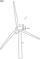
- Figure 1 shows a wind turbine with a number of hoist windows
- Figure 2 and Figure 3 show embodiments of the inventive safety door assembly prior to a hoisting procedure
- Figures 4 - 12 show various stages of using an embodiment of the inventive safety door assembly during a hoisting procedure
- FIGS 13 and 14 show alternative realizations of the inventive safety door assembly
- Figure 15 shows a stage during a prior art hoisting procedure.
- Figure 1 shows a wind turbine 2 with a number of hoist windows 2HW.
- One hoist window 2HW is provided in a side wall of the canopy 20, and another possible position for a hoist window is indicated at the rear of the canopy 20.
- the position of another possible hoist window 2HW is indicated near the top of the tower 21. It is important to ensure that a person inside the canopy (or tower) is not exposed to any risk of falling through an open hoist window 2HW.
- FIG. 2 shows an embodiment of the inventive safety door assembly 1 prior to a hoisting procedure.
- the diagram shows a sliding door 10 in its closed position, i.e. in a position that closes off the hoist window 2HW (shown here as an aperture in a section of the canopy wall 200).
- the diagram also shows two barriers 11B of a barrier assembly 11.
- the barriers 11B are both open, and permit personnel to freely move about in front of the closed hoist window 2H.
- a passageway 25 or walkway 25 runs along the canopy wall, and installation of the safety door assembly 1 makes use of structural elements of the passageway 25.
- a hazard area 25X in front of the hoist window 2HW is indicated. It is important to ensure that no personnel is present in this particularly dangerous area 25X during a hoist manoeuvre.
- FIG 3 shows another embodiment of the inventive safety door assembly 1 prior to a hoisting procedure.
- a sliding door 10 is in its closed position and closes off a hoist window.
- the diagram also shows two barriers 11B of a barrier assembly 11, configured in this case to open in opposite directions, i.e. the left-hand barrier opens to the left, and the right-hand barrier opens to the right.
- the two barriers 11B are both open, and permit personnel to freely move along the passageway 25.
- a hook-shaped "parking lock” 110 is provided for each barrier 11B and is shown in more detail in Figure 12 .
- This hook-shaped mechanism allows the barrier to engage with the supporting framework 13 of the safety door assembly 1.
- This mechanism also prevents the sliding door 10 from being opened when a barrier is open (in its "parking" position to allow free passage); equally, this mechanism prevents a barrier from being opened as long as the sliding door 10 is open.
- Figures 4 - 12 show various stages of the inventive method during a hoisting procedure.
- the description relates to the safety door assembly of Figure 3 .
- a load 3 can be lifted into place outside the hoist window 2HW using a davit crane 4 installed inside the canopy 20.
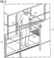
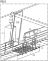
- an operator 5 has turned both barriers 11B to their closed position.
- the first barrier 11B (to the left of the hoist window) is closed by manually actuating a spring-loaded latch to release the barrier 11B from its "parked” position.
- a similar spring-loaded latch can be actuated to release the second barrier 11B (to the right of the hoist window) from its "parked” position.
- Each barrier 11B has a latch 112 that automatically engages with a handrail 250 of the walkway 25.
- the hazard area 25X is closed off.
- the operator 5 actuates a release mechanism 101 of the sliding door 10.
- the release mechanism 101 is a long lever which can only be raised when the operator 5 is in a position to the side of the hoist window 2HW, since the release mechanism 101 is constructed to be inaccessible from within the closed barrier assembly 11. In other words, from a position in the hazard area 25X, the operator 5 cannot reach or actuate the release mechanism 101 to open the sliding door 10.
- Figure 7 is a side view of the safety door assembly 1, and the canopy wall and hoist window are not shown for the sake of clarity.
- Figure 8 shows the cross-section F-F.
- the enlarged portion G indicates a spring-loaded release mechanism 113 for the barrier 11B on the left of the hoist window (when viewed from inside the canopy) which is manually actuated to release the barrier 11B from its "parked" position, allowing it to be moved to its closed position.
- a similar mechanism may be assumed to be present for the other barrier 11B (to the right of the hoist window when viewed from inside the canopy) to release it from its "parked" position.
- the diagrams show how the fully opened sliding door 10 prevents a barrier 11B from being returned to its open position. This is because the body of the sliding door 10 (shown here from behind) effectively blocks the locking mechanism 110 of the barrier 11B (on the left-hand side of the diagram), so that the barrier 11B cannot be turned to its open position. The other barrier 11B (on the right-hand side of this diagram) is also prevented from turning by the spring-loaded latch that now blocks its locking mechanism 110.
- Figure 12 shows another view of the safety door assembly 1 from behind, showing the barriers 11B of the barrier assembly 11 in their open position.
- the locking mechanism 110 is realised as a pair of flat hooks that pass through horizontal slits 111 formed in the body of the sliding door 10.
- Figures 7 and 8 were used to explain how the opened sliding door 10 prevents a closed barrier from being opened; this diagram shows how the locking mechanism 110 of a barrier 11B engages with the sliding door 10 in its closed position, preventing the sliding door 10 from being opened.
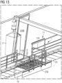
- Figures 13 and 14 show alternative approaches to implementing the inventive safety door assembly.
- the safety door assembly 1 deploys a sliding door 10 that can move vertically as indicated by the arrow.
- the diagram shows the sliding door 10 in its open position, allowing a load 3 to be moved through the hoist window 2HW during a lifting manoeuvre.
- the barrier assembly 11 can be the same in principle as the barrier assembly described above, and any locking means and/or actuating means can be adapted as appropriate so that the sliding door 10 cannot be moved downwards unless both barriers 11B are closed as shown here; and neither barrier 11B can be turned to its parking position unless the sliding door has been pulled up to its closed position.
- the barriers 11B can move vertically.
- the diagram shows a barrier 11B being moved from its open position, unfolding downwards towards its closed position.
- the other barrier 11B may be assumed to be the same.
- the diagram shows the sliding door 10 in its closed position, and it cannot move horizontally until both barriers 11B are fully closed, i.e. fully unfolded.
- a locking means 110 ensures that the sliding door 10 cannot be opened unless both barriers 11B are closed; and neither barrier 11B can be returned to its upright open position unless the sliding door 10 is correctly closed.
- FIG. 15 shows a stage during a prior art hoist procedure.
- the diagram shows a hoist window 2HW in a wind turbine canopy 20.
- a platform 25 extends along the inside wall of the wind turbine canopy 20 and can be used by personnel 5 at various stages of a lifting manoeuvre.
- the diagram shows a load 3 deposited on the platform 25, and a person 5 attaching a lifting apparatus 4 to the load 3.
- a safety harness 6 which in turn must be securely attached by means of a rope or cable to a fixture 60 inside the canopy 20. This safety measure is important, but the harness and rope can also hamper his movements and can significantly prolong the duration of the overall lifting manoeuvre.
Landscapes
- Engineering & Computer Science (AREA)
- Mechanical Engineering (AREA)
- Structural Engineering (AREA)
- Civil Engineering (AREA)
- Architecture (AREA)
- Sustainable Energy (AREA)
- Chemical & Material Sciences (AREA)
- Combustion & Propulsion (AREA)
- Sustainable Development (AREA)
- General Engineering & Computer Science (AREA)
- Life Sciences & Earth Sciences (AREA)
- Wing Frames And Configurations (AREA)
- Power-Operated Mechanisms For Wings (AREA)
Abstract
Description
- In a tall structure such as a wind turbine, a tall building, a lighthouse etc., it may at some stage be necessary to carry out a load-lifting procedure at an upper level of the structure. For example, during a wind turbine installation procedure or during a maintenance procedure, a heavy object such as a generator component, an auxiliary device, etc. may need to be lifted to the height of the nacelle or canopy and then manoeuvred into the interior. Equally, a heavy object may need to be manoeuvred from the nacelle or canopy to the exterior and then lowered to ground level or, in the case of an offshore wind turbine, to the deck of a marine vessel. To this end, the canopy of a wind turbine generally has one or more access openings such as an access hatch or access window which can be opened to allow a load to be lifted in or out.
- It is very important to ensure the safety of any person in the vicinity of the opened hatch or window. Particularly at a great height such as at the top of a wind turbine tower, wind gusts can present a significant hazard to personnel near any open hatch or window. Therefore, safety regulations may stipulate that personnel wear a harness connected by rope to some fixed point in the interior to prevent anyone falling out of an opened hatch or window. However, in the confined interior of a wind turbine canopy, the need to wear a harness can make it difficult to move around and to operate a crane or hoist. The need to wear a harness may add multiple additional steps to the overall procedure, so that installation and maintenance become more time-consuming and also more costly.
- It is an object of the invention to provide a solution to the problem described above.
- This object is achieved by the claimed safety door assembly, by the claimed wind turbine, and by the claimed method of performing a hoisting procedure.
- The claimed safety door assembly shall be understood to be provided for a hoist window in an essentially vertical wall of a structure such as a wind turbine, a lighthouse, or any tall building. The safety door assembly serves to reduce or eliminate the risk of a person falling through the opened hoist window.
- According to the invention, the safety door assembly comprises a sliding door arranged to reveal or conceal the hoist window; and a barrier assembly which can be closed to inhibit personnel access to an area immediately in front of the hoist window, or opened to permit access to the area in front of the hoist window. The barrier assembly is adapted to prevent the sliding door from revealing the hoist window when the barrier assembly is open; and the sliding door is adapted to prevent opening of the closed barrier assembly when the sliding door reveals the hoist window.
- In the inventive safety door assembly, the sliding door cannot open unless the barrier assembly is closed: in other words, without the barrier in place, it is not possible to open the hoist window. Equally, the barrier assembly cannot be opened unless the sliding door is closed: in other words, the opened sliding door makes it impossible to remove the barrier from the area in front of the hoist window. The inventive safety door assembly may therefore be regarded as an interlocking system, since each of the barrier assembly and sliding door prevents the other from being moved to a potentially hazardous position.
- The inventive safety door assembly is essentially an interlocking guard system that makes it very difficult or even impossible for a technician or other personnel to unintentionally be present in front of the opened hoist window. The open/shut states of the sliding door are linked to open/shut states of the barrier in such a way that a technician must perform a certain sequence of actions in order to be able to open the hoist window, and can ultimately only actuate the sliding door to reveal the hoist window when he is no longer standing in front of the hoist window.
- The area in front of the hoist window can be a small platform on which a load can be placed during a hoisting manoeuvre. Equally, the area in front of the hoist window can be part of a larger platform or passageway. Because personnel are at risk of injury or accident when standing in this area when the hoist window is open, the area immediately in front of the hoist window may be referred to in the following as the "hoist window hazard zone". The inventive safety door assembly ensures that a technician cannot be present in this hazard zone when the hoist window is open, by making it necessary for the technician to move outside of the hoist window hazard zone in order for the hoist window to be opened.
- An advantage of the inventive safety door assembly is that the risk of injury or accident is very favourably reduced, so that personnel in the vicinity of the hoist window during a load hoisting manoeuvre need not wear a safety harness and can move about unhampered by such restrictions. The duration and expense of any service, maintenance or repair procedure being carried out can therefore be favourably reduced.
- According to the invention, the wind turbine comprises a canopy mounted at the top of a tower and enclosing components of the wind turbine; a number of rotor blades mounted to a hub at the front of the canopy; a hoist window to facilitate transfer of loads into and out of the wind turbine, and an embodiment of the inventive safety door assembly for the hoist window.
- As indicated above, the inventive safety door assembly can be deployed in any structure with a hoist window at a hazard-related height for the transfer of loads into or out of the structure.
- According to the invention, the method of performing a hoisting procedure in such a structure comprises the steps of:
- A) closing the barrier assembly to inhibit personnel access to the hazard area;
- B) actuating the sliding door to open the hoist window;
- C) operating a lifting apparatus to transfer a load through the opened hoist window;
- D) actuating the sliding door to close the hoist window; and
- E) opening the barrier assembly to permit personnel access once again to the hazard area.
- Particularly advantageous embodiments and features of the invention are given by the dependent claims, as revealed in the following description. Features of different claim categories may be combined as appropriate to give further embodiments not described herein.
- In the following, it may be assumed that the structure with the hoist window(s) is a wind turbine, which can reach a height of 80 m or more. A hoist window in the side of the wind turbine canopy can therefore be at a height of 80 m or higher above ground or sea level, and it is mandatory to ensure the safety of personnel in the vicinity of any such opened hoist window, which may also be referred to as a service hatch, a transfer hatch, etc. The components requiring replacement and service procedures may be mostly arranged inside the canopy (the terms "canopy" and "nacelle" may be regarded as synonyms). In a preferred embodiment of the invention, a wind turbine may comprise a number of hoist windows, each being an aperture or opening in an essentially vertical side wall of the canopy (the term "essentially vertical" does not exclude that the wall containing the hoist window can be slanted, curved, etc.), and a safety door assembly for each such hoist window. Other components may be installed at an upper level of the tower. Equally, it may be preferred to move components into or out of the canopy through the tower. In a preferred embodiment of the invention therefore, the wind turbine comprises a hoist window at an upper level of the tower, and a safety door assembly for that hoist window. A wind turbine may also have a hoist window in the hub to allow components to be lifted into or out of the hub or spinner. For example, a hoist window may be provided in the flat front face of a hub, or in the curved side wall of a hub, depending on the hub design and geometry. The wind turbine preferably also comprises a safety door assembly for such a hoist window in the hub. The sliding door and barrier assembly may be configured to allow the hoist window to open for any rotational position of the hub. Alternatively, the sliding door and barrier assembly may be configured to allow the hoist window to open when the hub is in a specific rotational position.
- The area immediately in front of the hoist window may be at a raised level. For example, a raised passageway, platform or walkway may be provided along a section of the canopy side wall, and personnel may use this passageway to move about inside the canopy. In a preferred embodiment of the invention, the width of the passageway corresponds to the width of the barrier assembly in its closed state. In other words, when the barrier assembly is closed, the area immediately in front of the hoist window is closed off and personnel cannot pass in front of the hoist window.
- There are various possible ways of constructing and realizing the barrier assembly. For example, the barrier assembly may be constructed to retract below the level of the passageway when in its "open" state, i.e. in a state that allows personnel to move in an unobstructed manner in front of the closed hoist window, and to be raised upwards when the hazard area is to be closed off. Alternatively, the barrier assembly may be constructed to be raised to a height above the hoist window when in its open state so that personnel can move freely in front of the closed hoist window, and to be lowered into place on a passageway or walkway when the hazard area is to be closed off. In either of these realizations, it shall be understood that the open barrier assembly acts to keep the sliding door closed (the sliding door can only open when the barrier assembly is closed); and the open sliding door acts to keep the barrier assembly closed (the barrier assembly can only open when the sliding door is closed).
- In a particularly preferred embodiment of the invention, the barrier assembly comprises a pair of barriers arranged on either side of the hoist window. Preferably, the barriers are independently operable. In one possible embodiment, each barrier is mounted to a supporting structure or framework which also supports the sliding door. For example, the supporting structure may comprise an essentially rectangular frame and track that allows the sliding door to slide freely between its closed position (concealing the hoist window opening) and its open position (revealing the hoist window opening). One barrier may be mounted to the left-hand side of the frame, and the other barrier may be mounted to the right-hand side of the frame. For example, the supporting structure can comprise a vertical post on each side, and each barrier can be rotatably mounted to such a post. In a preferred embodiment of the invention, each barrier can swing through one quarter-turn from its open position to its closed position. Preferably, a barrier extends across a passageway or walkway when closed, and comprises a latch mechanism to engage with a fixed structure during its closed state. For example, each of the two barriers described above may be equipped with a latch that can engage with a handrail present along the outer edge of the passageway.
- The sliding door may be equipped with a mechanical and/or magnetic and/or electrical actuating means. In a particularly preferred embodiment of the invention, the actuating means of the sliding door is arranged to be inaccessible, i.e. physically unreachable, to a person in front of the hoist window. This means that to open or close the sliding door, a person must be outside the hazard area. In a particularly preferred embodiment of the invention, the sliding door actuating means is realised as a lever which, when raised, allows the sliding door to be moved to reveal the hoist window. The lever can be arranged at the outer side of the closed sliding door so that it can only be reached by a person standing outside of the hazard area.
- Because of the location of the actuating mechanism, even when the barrier assembly has been actuated to close off the passageway, it is not possible for a person standing within the closed barrier assembly to open the sliding door. In order to reach the actuating mechanism, that person must be outside the hazard zone, for example that person cannot be in the area between the two barriers of the barrier assembly described above.
- Components of the inventive safety door assembly may be actuated manually, by an electronic control means, or using any suitable mode. For example, an additional level of safety may be provided by only permitting trained personnel to actuate the safety door assembly using authorization such as a key card, and a suitable card reader may be installed in the vicinity of the hoist window. Alternatively or in addition, a dedicated tool may be required to operate the actuating means of the sliding door and/or to actuate a barrier of the barrier assembly.
- Other objects and features of the present invention will become apparent from the following detailed descriptions considered in conjunction with the accompanying drawings. It is to be understood, however, that the drawings are designed solely for the purposes of illustration and not as a definition of the limits of the invention.
-
Figure 1 shows a wind turbine with a number of hoist windows; -
Figure 2 andFigure 3 show embodiments of the inventive safety door assembly prior to a hoisting procedure; -
Figures 4 - 12 show various stages of using an embodiment of the inventive safety door assembly during a hoisting procedure; -
Figures 13 and14 show alternative realizations of the inventive safety door assembly; -
Figure 15 shows a stage during a prior art hoisting procedure. - In the diagrams, like numbers refer to like objects throughout. Objects in the diagrams are not necessarily drawn to scale.
-
Figure 1 shows awind turbine 2 with a number of hoist windows 2HW. One hoist window 2HW is provided in a side wall of thecanopy 20, and another possible position for a hoist window is indicated at the rear of thecanopy 20. The position of another possible hoist window 2HW is indicated near the top of thetower 21. It is important to ensure that a person inside the canopy (or tower) is not exposed to any risk of falling through an open hoist window 2HW. -
Figure 2 shows an embodiment of the inventive safety door assembly 1 prior to a hoisting procedure. The diagram shows a slidingdoor 10 in its closed position, i.e. in a position that closes off the hoist window 2HW (shown here as an aperture in a section of the canopy wall 200). The diagram also shows twobarriers 11B of abarrier assembly 11. Thebarriers 11B are both open, and permit personnel to freely move about in front of the closed hoist window 2H. In this exemplary realisation, apassageway 25 orwalkway 25 runs along the canopy wall, and installation of the safety door assembly 1 makes use of structural elements of thepassageway 25. Ahazard area 25X in front of the hoist window 2HW is indicated. It is important to ensure that no personnel is present in this particularlydangerous area 25X during a hoist manoeuvre. -
Figure 3 shows another embodiment of the inventive safety door assembly 1 prior to a hoisting procedure. Here also, a slidingdoor 10 is in its closed position and closes off a hoist window. The diagram also shows twobarriers 11B of abarrier assembly 11, configured in this case to open in opposite directions, i.e. the left-hand barrier opens to the left, and the right-hand barrier opens to the right. In this diagram, the twobarriers 11B are both open, and permit personnel to freely move along thepassageway 25. A hook-shaped "parking lock" 110 is provided for eachbarrier 11B and is shown in more detail inFigure 12 . This hook-shaped mechanism allows the barrier to engage with the supporting framework 13 of the safety door assembly 1. This mechanism also prevents the slidingdoor 10 from being opened when a barrier is open (in its "parking" position to allow free passage); equally, this mechanism prevents a barrier from being opened as long as the slidingdoor 10 is open. -
Figures 4 - 12 show various stages of the inventive method during a hoisting procedure. The description relates to the safety door assembly ofFigure 3 . As shown inFigure 4 , aload 3 can be lifted into place outside the hoist window 2HW using adavit crane 4 installed inside thecanopy 20. In a subsequent step shown inFigure 5 andFigure 6 , an operator 5 has turned bothbarriers 11B to their closed position. Thefirst barrier 11B (to the left of the hoist window) is closed by manually actuating a spring-loaded latch to release thebarrier 11B from its "parked" position. A similar spring-loaded latch can be actuated to release thesecond barrier 11B (to the right of the hoist window) from its "parked" position. - Each
barrier 11B has alatch 112 that automatically engages with ahandrail 250 of thewalkway 25. To any person on thepassageway 25, it is immediately obvious that thehazard area 25X is closed off. As shown inFigure 5 , the operator 5 actuates arelease mechanism 101 of the slidingdoor 10. In this embodiment, therelease mechanism 101 is a long lever which can only be raised when the operator 5 is in a position to the side of the hoist window 2HW, since therelease mechanism 101 is constructed to be inaccessible from within the closedbarrier assembly 11. In other words, from a position in thehazard area 25X, the operator 5 cannot reach or actuate therelease mechanism 101 to open the slidingdoor 10. -
Figure 7 is a side view of the safety door assembly 1, and the canopy wall and hoist window are not shown for the sake of clarity.Figure 8 shows the cross-section F-F. The enlarged portion G indicates a spring-loadedrelease mechanism 113 for thebarrier 11B on the left of the hoist window (when viewed from inside the canopy) which is manually actuated to release thebarrier 11B from its "parked" position, allowing it to be moved to its closed position. A similar mechanism may be assumed to be present for theother barrier 11B (to the right of the hoist window when viewed from inside the canopy) to release it from its "parked" position. - The diagrams show how the fully opened sliding
door 10 prevents abarrier 11B from being returned to its open position. This is because the body of the sliding door 10 (shown here from behind) effectively blocks thelocking mechanism 110 of thebarrier 11B (on the left-hand side of the diagram), so that thebarrier 11B cannot be turned to its open position. Theother barrier 11B (on the right-hand side of this diagram) is also prevented from turning by the spring-loaded latch that now blocks itslocking mechanism 110. - With both
barriers 11B closed and the sliding door open, thehazard area 25X is now inaccessible to personnel, and the hoisting procedure can continue safely as shown inFigures 9 - 11 , which illustrate how theload 3 may be lifted in through the hoist window 2HW and onto theplatform 25. The operator can then close the slidingdoor 10, and then open the right-hand barrier 11B as shown inFigure 11 to allow the load to be moved outside of thehazard area 25X. Theother barrier 11B can then also be opened to once again give free passage to anyone on thewalkway 25. -
Figure 12 shows another view of the safety door assembly 1 from behind, showing thebarriers 11B of thebarrier assembly 11 in their open position. As shown inFigures 7 and 8 , thelocking mechanism 110 is realised as a pair of flat hooks that pass throughhorizontal slits 111 formed in the body of the slidingdoor 10.Figures 7 and 8 were used to explain how the opened slidingdoor 10 prevents a closed barrier from being opened; this diagram shows how thelocking mechanism 110 of abarrier 11B engages with the slidingdoor 10 in its closed position, preventing the slidingdoor 10 from being opened. -
Figures 13 and14 show alternative approaches to implementing the inventive safety door assembly. InFigure 13 , the safety door assembly 1 deploys a slidingdoor 10 that can move vertically as indicated by the arrow. The diagram shows the slidingdoor 10 in its open position, allowing aload 3 to be moved through the hoist window 2HW during a lifting manoeuvre. Thebarrier assembly 11 can be the same in principle as the barrier assembly described above, and any locking means and/or actuating means can be adapted as appropriate so that the slidingdoor 10 cannot be moved downwards unless bothbarriers 11B are closed as shown here; and neitherbarrier 11B can be turned to its parking position unless the sliding door has been pulled up to its closed position. - In
Figure 14 , instead of swinging sideways, thebarriers 11B can move vertically. The diagram shows abarrier 11B being moved from its open position, unfolding downwards towards its closed position. Theother barrier 11B may be assumed to be the same. The diagram shows the slidingdoor 10 in its closed position, and it cannot move horizontally until bothbarriers 11B are fully closed, i.e. fully unfolded. Here also, a locking means 110 ensures that the slidingdoor 10 cannot be opened unless bothbarriers 11B are closed; and neitherbarrier 11B can be returned to its upright open position unless the slidingdoor 10 is correctly closed. -
Figure 15 shows a stage during a prior art hoist procedure. The diagram shows a hoist window 2HW in awind turbine canopy 20. Aplatform 25 extends along the inside wall of thewind turbine canopy 20 and can be used by personnel 5 at various stages of a lifting manoeuvre. The diagram shows aload 3 deposited on theplatform 25, and a person 5 attaching alifting apparatus 4 to theload 3. To avoid serious injury, he must wear a safety harness 6 which in turn must be securely attached by means of a rope or cable to afixture 60 inside thecanopy 20. This safety measure is important, but the harness and rope can also hamper his movements and can significantly prolong the duration of the overall lifting manoeuvre. - Although the present invention has been disclosed in the form of preferred embodiments and variations thereon, it will be understood that numerous additional modifications and variations could be made thereto without departing from the scope of the invention.
- For the sake of clarity, it is to be understood that the use of "a" or "an" throughout this application does not exclude a plurality, and "comprising" does not exclude other steps or elements.
Claims (15)
- A safety door assembly (1) for a hoist window (2HW) of a structure (2), which safety door assembly (1) comprises- a sliding door (10) arranged to reveal or conceal the hoist window (2HW); and- a barrier assembly (11) which can be closed to inhibit access to an area (25X) in front of the hoist window (2HW) or opened to permit access to the area (25X) in front of the hoist window (2HW);characterized in thatthe barrier assembly (11) is adapted to prevent the sliding door (10) from revealing the hoist window (2HW) when the barrier assembly (11) is open; andthe sliding door (10) is adapted to prevent opening of the closed barrier assembly (11) when the sliding door reveals the hoist window (2HW).
- A safety door assembly according to the preceding claim, comprising an actuating means (101) for actuating the sliding door (10), which actuating means (101) is arranged to be inaccessible from a position (25X) in front of the hoist window (2HW).
- A safety door assembly according to any of the preceding claims, wherein the actuating means comprises a lever (101) which, when raised, allows the sliding door (10) to be moved to reveal the hoist window (2HW).
- A safety door assembly according to the preceding claim, wherein the lever (101), when lowered, prevents movement of the sliding door (10).
- A safety door assembly according to any of the preceding claims, wherein the barrier assembly (11) comprises a pair of barriers (11B) arranged on either side of the hoist window (2HW) .
- A safety door assembly according to the preceding claim, wherein the barriers (11B) are independently operable between an open position and a closed position.
- A safety door assembly according to any of the preceding claims, wherein the barrier assembly (11) extends across a passageway (25) when closed.
- A safety door assembly according to any of the preceding claims, wherein the barrier assembly (11) comprises a locking means (110) adapted to engage with the sliding door (10) when the barrier assembly (11) is in its open position.
- A safety door assembly according to any of the preceding claims, wherein the locking means (110) comprises a hook, and wherein the sliding door (10) comprises an aperture (111) shaped to receive the locking means (110) when the sliding door (10) is in its closed position.
- A safety door assembly according to any of the preceding claims, wherein the barrier assembly (11) comprises a latch (112) adapted to engage with a railing (250) of a passageway (25) when the barrier assembly (11) is in its closed position.
- A wind turbine (2) comprising- a canopy (20) mounted at the top of a tower (21) and enclosing components of the wind turbine (2); and- a hoist window (2HW) to facilitate transfer of loads into and out of the wind turbine (2), and a safety door assembly (1) according to any of claims 1 to 10 for the hoist window (2HW).
- A wind turbine according to the preceding claim, comprising a safety door assembly (1) for a hoist window (2HW) in the side wall (200) of the canopy (20).
- A wind turbine according to claim 11 or claim 12, comprising a safety door assembly (1) for a hoist window (2HW) in the tower wall (21).
- A wind turbine according to any of claims 11 to 13, comprising a passageway (25) beneath a hoist window (2HW) and wherein the width of the passageway (25) corresponds to the width of a barrier (11B) of the barrier assembly (11).
- A method of performing a hoisting procedure in a structure (2) comprising a hoist window (2HW) to facilitate the transfer of a load (3) between the interior and exterior of the structure (2) and comprising a safety door assembly (1) according to any of claims 1 to 10, which method comprises the steps of:A) closing the barrier assembly (11) to inhibit personnel access to the area (25X) in front of the hoist window (2HW);B) actuating the sliding door (10) to reveal the hoist window (2HW);C) operating a lifting apparatus (4) to transfer the load (3) through the opened hoist window (2HW);D) actuating the sliding door (10) to conceal the hoist window (2HW); andE) opening the barrier assembly (11) to permit personnel access once again to the area (25X) in front of the closed hoist window (2HW).
Priority Applications (3)
| Application Number | Priority Date | Filing Date | Title |
|---|---|---|---|
| EP22151556.2A EP4212723B1 (en) | 2022-01-14 | 2022-01-14 | Safety door assembly |
| US18/094,139 US12234675B2 (en) | 2022-01-14 | 2023-01-06 | Safety door assembly |
| CN202310037156.6A CN116446779B (en) | 2022-01-14 | 2023-01-10 | Security door assembly |
Applications Claiming Priority (1)
| Application Number | Priority Date | Filing Date | Title |
|---|---|---|---|
| EP22151556.2A EP4212723B1 (en) | 2022-01-14 | 2022-01-14 | Safety door assembly |
Publications (2)
| Publication Number | Publication Date |
|---|---|
| EP4212723A1 true EP4212723A1 (en) | 2023-07-19 |
| EP4212723B1 EP4212723B1 (en) | 2025-03-12 |
Family
ID=79730461
Family Applications (1)
| Application Number | Title | Priority Date | Filing Date |
|---|---|---|---|
| EP22151556.2A Active EP4212723B1 (en) | 2022-01-14 | 2022-01-14 | Safety door assembly |
Country Status (3)
| Country | Link |
|---|---|
| US (1) | US12234675B2 (en) |
| EP (1) | EP4212723B1 (en) |
| CN (1) | CN116446779B (en) |
Families Citing this family (1)
| Publication number | Priority date | Publication date | Assignee | Title |
|---|---|---|---|---|
| KR102822096B1 (en) * | 2025-01-03 | 2025-06-18 | 김원석 | Safty deck for coil steel plate |
Citations (2)
| Publication number | Priority date | Publication date | Assignee | Title |
|---|---|---|---|---|
| CN208980153U (en) * | 2018-09-05 | 2019-06-14 | 南京风电科技有限公司 | A kind of hanging object device for wind turbine |
| WO2021063646A1 (en) * | 2019-10-01 | 2021-04-08 | Siemens Gamesa Renewable Energy A/S | Nacelle housing with service hatch |
Family Cites Families (7)
| Publication number | Priority date | Publication date | Assignee | Title |
|---|---|---|---|---|
| ES2594232T3 (en) * | 2010-12-27 | 2016-12-16 | Areva Wind Gmbh | Gate cover for a wind power plant |
| DE102013207908A1 (en) * | 2013-04-30 | 2014-10-30 | Wobben Properties Gmbh | Wind turbine and wind turbine tower |
| US10982659B2 (en) * | 2016-09-21 | 2021-04-20 | Vestas Wind Systems A/S | Method for opening a cover portion of a wind turbine |
| FR3068724B1 (en) * | 2017-07-07 | 2020-11-13 | Erga | LOCK BARRIER |
| EP3786451A1 (en) * | 2019-08-28 | 2021-03-03 | Siemens Gamesa Renewable Energy A/S | Wind turbine |
| EP3828409B1 (en) * | 2019-11-27 | 2023-10-25 | Siemens Gamesa Renewable Energy A/S | Hatch arrangement for closing an opening in a floor of a wind turbine and wind turbine |
| EP3926168A1 (en) * | 2020-06-17 | 2021-12-22 | Siemens Gamesa Renewable Energy A/S | Tower of a wind turbine |
-
2022
- 2022-01-14 EP EP22151556.2A patent/EP4212723B1/en active Active
-
2023
- 2023-01-06 US US18/094,139 patent/US12234675B2/en active Active
- 2023-01-10 CN CN202310037156.6A patent/CN116446779B/en active Active
Patent Citations (2)
| Publication number | Priority date | Publication date | Assignee | Title |
|---|---|---|---|---|
| CN208980153U (en) * | 2018-09-05 | 2019-06-14 | 南京风电科技有限公司 | A kind of hanging object device for wind turbine |
| WO2021063646A1 (en) * | 2019-10-01 | 2021-04-08 | Siemens Gamesa Renewable Energy A/S | Nacelle housing with service hatch |
Also Published As
| Publication number | Publication date |
|---|---|
| US20230228134A1 (en) | 2023-07-20 |
| EP4212723B1 (en) | 2025-03-12 |
| CN116446779A (en) | 2023-07-18 |
| US12234675B2 (en) | 2025-02-25 |
| CN116446779B (en) | 2025-11-11 |
Similar Documents
| Publication | Publication Date | Title |
|---|---|---|
| US9382099B2 (en) | Motorized height access device for tower cranes | |
| US20100101086A1 (en) | Device and process for rapid disassembly of a rotor and a nacelle from the mast of a windmill, as well as a windmill that is equipped with such a device | |
| US8369057B2 (en) | Remote locking roof access hatch | |
| JP6296249B2 (en) | Very large elevator for building large ships and offshore plants | |
| CN112587823A (en) | Anti-falling device based on unmanned aerial vehicle suspension and suspension method thereof | |
| WO2020156709A1 (en) | A wind turbine and a method for transporting cargo inside a wind turbine | |
| US12234675B2 (en) | Safety door assembly | |
| CN106904516A (en) | For the method and apparatus of elevator maintenance operation | |
| CN105692380B (en) | A kind of tracking-driven elevator maintenance protection system peculiar to vessel | |
| DE102006034299A1 (en) | Wind turbine is fitted with lift which moves up outside of tower, lift motor, etc. being mounted at rear of gondola | |
| DE102004033681A1 (en) | Wind turbine with a tower | |
| CN118854875A (en) | An offshore wind turbine foundation platform lifting system | |
| CN216836689U (en) | Marine sightseeing passenger ladder escape device | |
| CN214740558U (en) | A safety device for crane girder walkway and trolley frame | |
| KR101436270B1 (en) | Wind energy installation working gantry and wind energy installation | |
| CN113982866B (en) | A side-opening functional wind turbine nacelle and working method thereof | |
| KR101561080B1 (en) | Emergency escape system for elevator | |
| WO2019097105A1 (en) | Elevator arrangement | |
| CN223646113U (en) | Wind turbine tower lifting hole cover plate equipment | |
| CN109854134A (en) | A kind of workshop automatic lifting gate | |
| KR102208148B1 (en) | Rotation apparatus system of rotation bridge and method of controlling rotation thereof | |
| CN116495680A (en) | Protective device for construction lifter and operation method | |
| KR101635083B1 (en) | Opening and closing system of handrail | |
| CN113294027A (en) | Safety device for crane girder walkway and trolley frame and judgment method thereof | |
| JP3619803B2 (en) | Maintenance device for wall mounted array antenna |
Legal Events
| Date | Code | Title | Description |
|---|---|---|---|
| PUAI | Public reference made under article 153(3) epc to a published international application that has entered the european phase |
Free format text: ORIGINAL CODE: 0009012 |
|
| STAA | Information on the status of an ep patent application or granted ep patent |
Free format text: STATUS: THE APPLICATION HAS BEEN PUBLISHED |
|
| AK | Designated contracting states |
Kind code of ref document: A1 Designated state(s): AL AT BE BG CH CY CZ DE DK EE ES FI FR GB GR HR HU IE IS IT LI LT LU LV MC MK MT NL NO PL PT RO RS SE SI SK SM TR |
|
| STAA | Information on the status of an ep patent application or granted ep patent |
Free format text: STATUS: REQUEST FOR EXAMINATION WAS MADE |
|
| 17P | Request for examination filed |
Effective date: 20240119 |
|
| RBV | Designated contracting states (corrected) |
Designated state(s): AL AT BE BG CH CY CZ DE DK EE ES FI FR GB GR HR HU IE IS IT LI LT LU LV MC MK MT NL NO PL PT RO RS SE SI SK SM TR |
|
| STAA | Information on the status of an ep patent application or granted ep patent |
Free format text: STATUS: EXAMINATION IS IN PROGRESS |
|
| 17Q | First examination report despatched |
Effective date: 20240705 |
|
| REG | Reference to a national code |
Ref country code: DE Ref legal event code: R079 Free format text: PREVIOUS MAIN CLASS: F03D0080500000 Ipc: F03D0001000000 Ref country code: DE Ref legal event code: R079 Ref document number: 602022011563 Country of ref document: DE Free format text: PREVIOUS MAIN CLASS: F03D0080500000 Ipc: F03D0001000000 |
|
| GRAP | Despatch of communication of intention to grant a patent |
Free format text: ORIGINAL CODE: EPIDOSNIGR1 |
|
| STAA | Information on the status of an ep patent application or granted ep patent |
Free format text: STATUS: GRANT OF PATENT IS INTENDED |
|
| RIC1 | Information provided on ipc code assigned before grant |
Ipc: B66C 23/20 20060101ALI20241017BHEP Ipc: F03D 80/50 20160101ALI20241017BHEP Ipc: F03D 1/00 20060101AFI20241017BHEP |
|
| INTG | Intention to grant announced |
Effective date: 20241028 |
|
| GRAS | Grant fee paid |
Free format text: ORIGINAL CODE: EPIDOSNIGR3 |
|
| GRAA | (expected) grant |
Free format text: ORIGINAL CODE: 0009210 |
|
| STAA | Information on the status of an ep patent application or granted ep patent |
Free format text: STATUS: THE PATENT HAS BEEN GRANTED |
|
| AK | Designated contracting states |
Kind code of ref document: B1 Designated state(s): AL AT BE BG CH CY CZ DE DK EE ES FI FR GB GR HR HU IE IS IT LI LT LU LV MC MK MT NL NO PL PT RO RS SE SI SK SM TR |
|
| REG | Reference to a national code |
Ref country code: GB Ref legal event code: FG4D |
|
| REG | Reference to a national code |
Ref country code: CH Ref legal event code: EP |
|
| REG | Reference to a national code |
Ref country code: DE Ref legal event code: R096 Ref document number: 602022011563 Country of ref document: DE |
|
| REG | Reference to a national code |
Ref country code: IE Ref legal event code: FG4D |
|
| PG25 | Lapsed in a contracting state [announced via postgrant information from national office to epo] |
Ref country code: RS Free format text: LAPSE BECAUSE OF FAILURE TO SUBMIT A TRANSLATION OF THE DESCRIPTION OR TO PAY THE FEE WITHIN THE PRESCRIBED TIME-LIMIT Effective date: 20250612 |
|
| PG25 | Lapsed in a contracting state [announced via postgrant information from national office to epo] |
Ref country code: FI Free format text: LAPSE BECAUSE OF FAILURE TO SUBMIT A TRANSLATION OF THE DESCRIPTION OR TO PAY THE FEE WITHIN THE PRESCRIBED TIME-LIMIT Effective date: 20250312 |
|
| PG25 | Lapsed in a contracting state [announced via postgrant information from national office to epo] |
Ref country code: ES Free format text: LAPSE BECAUSE OF FAILURE TO SUBMIT A TRANSLATION OF THE DESCRIPTION OR TO PAY THE FEE WITHIN THE PRESCRIBED TIME-LIMIT Effective date: 20250312 |
|
| REG | Reference to a national code |
Ref country code: LT Ref legal event code: MG9D |
|
| PG25 | Lapsed in a contracting state [announced via postgrant information from national office to epo] |
Ref country code: NO Free format text: LAPSE BECAUSE OF FAILURE TO SUBMIT A TRANSLATION OF THE DESCRIPTION OR TO PAY THE FEE WITHIN THE PRESCRIBED TIME-LIMIT Effective date: 20250612 |
|
| PG25 | Lapsed in a contracting state [announced via postgrant information from national office to epo] |
Ref country code: HR Free format text: LAPSE BECAUSE OF FAILURE TO SUBMIT A TRANSLATION OF THE DESCRIPTION OR TO PAY THE FEE WITHIN THE PRESCRIBED TIME-LIMIT Effective date: 20250312 |
|
| REG | Reference to a national code |
Ref country code: NL Ref legal event code: MP Effective date: 20250312 |
|
| PG25 | Lapsed in a contracting state [announced via postgrant information from national office to epo] |
Ref country code: LV Free format text: LAPSE BECAUSE OF FAILURE TO SUBMIT A TRANSLATION OF THE DESCRIPTION OR TO PAY THE FEE WITHIN THE PRESCRIBED TIME-LIMIT Effective date: 20250312 |
|
| PG25 | Lapsed in a contracting state [announced via postgrant information from national office to epo] |
Ref country code: BG Free format text: LAPSE BECAUSE OF FAILURE TO SUBMIT A TRANSLATION OF THE DESCRIPTION OR TO PAY THE FEE WITHIN THE PRESCRIBED TIME-LIMIT Effective date: 20250312 Ref country code: GR Free format text: LAPSE BECAUSE OF FAILURE TO SUBMIT A TRANSLATION OF THE DESCRIPTION OR TO PAY THE FEE WITHIN THE PRESCRIBED TIME-LIMIT Effective date: 20250613 |
|
| REG | Reference to a national code |
Ref country code: AT Ref legal event code: MK05 Ref document number: 1775179 Country of ref document: AT Kind code of ref document: T Effective date: 20250312 |
|
| PG25 | Lapsed in a contracting state [announced via postgrant information from national office to epo] |
Ref country code: NL Free format text: LAPSE BECAUSE OF FAILURE TO SUBMIT A TRANSLATION OF THE DESCRIPTION OR TO PAY THE FEE WITHIN THE PRESCRIBED TIME-LIMIT Effective date: 20250312 |
|
| PG25 | Lapsed in a contracting state [announced via postgrant information from national office to epo] |
Ref country code: SE Free format text: LAPSE BECAUSE OF FAILURE TO SUBMIT A TRANSLATION OF THE DESCRIPTION OR TO PAY THE FEE WITHIN THE PRESCRIBED TIME-LIMIT Effective date: 20250312 |
|
| PG25 | Lapsed in a contracting state [announced via postgrant information from national office to epo] |
Ref country code: SM Free format text: LAPSE BECAUSE OF FAILURE TO SUBMIT A TRANSLATION OF THE DESCRIPTION OR TO PAY THE FEE WITHIN THE PRESCRIBED TIME-LIMIT Effective date: 20250312 |
|
| PG25 | Lapsed in a contracting state [announced via postgrant information from national office to epo] |
Ref country code: PT Free format text: LAPSE BECAUSE OF FAILURE TO SUBMIT A TRANSLATION OF THE DESCRIPTION OR TO PAY THE FEE WITHIN THE PRESCRIBED TIME-LIMIT Effective date: 20250714 |
|
| PG25 | Lapsed in a contracting state [announced via postgrant information from national office to epo] |
Ref country code: IT Free format text: LAPSE BECAUSE OF FAILURE TO SUBMIT A TRANSLATION OF THE DESCRIPTION OR TO PAY THE FEE WITHIN THE PRESCRIBED TIME-LIMIT Effective date: 20250312 Ref country code: PL Free format text: LAPSE BECAUSE OF FAILURE TO SUBMIT A TRANSLATION OF THE DESCRIPTION OR TO PAY THE FEE WITHIN THE PRESCRIBED TIME-LIMIT Effective date: 20250312 |
|
| PG25 | Lapsed in a contracting state [announced via postgrant information from national office to epo] |
Ref country code: AT Free format text: LAPSE BECAUSE OF FAILURE TO SUBMIT A TRANSLATION OF THE DESCRIPTION OR TO PAY THE FEE WITHIN THE PRESCRIBED TIME-LIMIT Effective date: 20250312 |
|
| PG25 | Lapsed in a contracting state [announced via postgrant information from national office to epo] |
Ref country code: EE Free format text: LAPSE BECAUSE OF FAILURE TO SUBMIT A TRANSLATION OF THE DESCRIPTION OR TO PAY THE FEE WITHIN THE PRESCRIBED TIME-LIMIT Effective date: 20250312 Ref country code: CZ Free format text: LAPSE BECAUSE OF FAILURE TO SUBMIT A TRANSLATION OF THE DESCRIPTION OR TO PAY THE FEE WITHIN THE PRESCRIBED TIME-LIMIT Effective date: 20250312 |
|
| PG25 | Lapsed in a contracting state [announced via postgrant information from national office to epo] |
Ref country code: RO Free format text: LAPSE BECAUSE OF FAILURE TO SUBMIT A TRANSLATION OF THE DESCRIPTION OR TO PAY THE FEE WITHIN THE PRESCRIBED TIME-LIMIT Effective date: 20250312 |
|
| PG25 | Lapsed in a contracting state [announced via postgrant information from national office to epo] |
Ref country code: SK Free format text: LAPSE BECAUSE OF FAILURE TO SUBMIT A TRANSLATION OF THE DESCRIPTION OR TO PAY THE FEE WITHIN THE PRESCRIBED TIME-LIMIT Effective date: 20250312 |
|
| PG25 | Lapsed in a contracting state [announced via postgrant information from national office to epo] |
Ref country code: IS Free format text: LAPSE BECAUSE OF FAILURE TO SUBMIT A TRANSLATION OF THE DESCRIPTION OR TO PAY THE FEE WITHIN THE PRESCRIBED TIME-LIMIT Effective date: 20250712 |
|
| REG | Reference to a national code |
Ref country code: DE Ref legal event code: R097 Ref document number: 602022011563 Country of ref document: DE |
|
| PG25 | Lapsed in a contracting state [announced via postgrant information from national office to epo] |
Ref country code: DK Free format text: LAPSE BECAUSE OF FAILURE TO SUBMIT A TRANSLATION OF THE DESCRIPTION OR TO PAY THE FEE WITHIN THE PRESCRIBED TIME-LIMIT Effective date: 20250312 |
|
| PLBE | No opposition filed within time limit |
Free format text: ORIGINAL CODE: 0009261 |
|
| STAA | Information on the status of an ep patent application or granted ep patent |
Free format text: STATUS: NO OPPOSITION FILED WITHIN TIME LIMIT |
|
| REG | Reference to a national code |
Ref country code: CH Ref legal event code: L10 Free format text: ST27 STATUS EVENT CODE: U-0-0-L10-L00 (AS PROVIDED BY THE NATIONAL OFFICE) Effective date: 20260121 |
|
| 26N | No opposition filed |
Effective date: 20251215 |
|
| PGFP | Annual fee paid to national office [announced via postgrant information from national office to epo] |
Ref country code: GB Payment date: 20260126 Year of fee payment: 5 |
|
| PGFP | Annual fee paid to national office [announced via postgrant information from national office to epo] |
Ref country code: DE Payment date: 20250829 Year of fee payment: 5 |
|
| PGFP | Annual fee paid to national office [announced via postgrant information from national office to epo] |
Ref country code: FR Payment date: 20260126 Year of fee payment: 5 |