EP4212718A1 - Method and device for individually pitching blades of a wind turbine - Google Patents
Method and device for individually pitching blades of a wind turbine Download PDFInfo
- Publication number
- EP4212718A1 EP4212718A1 EP22151367.4A EP22151367A EP4212718A1 EP 4212718 A1 EP4212718 A1 EP 4212718A1 EP 22151367 A EP22151367 A EP 22151367A EP 4212718 A1 EP4212718 A1 EP 4212718A1
- Authority
- EP
- European Patent Office
- Prior art keywords
- blade
- pitch
- individual
- pitch reference
- collective
- Prior art date
- Legal status (The legal status is an assumption and is not a legal conclusion. Google has not performed a legal analysis and makes no representation as to the accuracy of the status listed.)
- Withdrawn
Links
Images


Classifications
-
- F—MECHANICAL ENGINEERING; LIGHTING; HEATING; WEAPONS; BLASTING
- F03—MACHINES OR ENGINES FOR LIQUIDS; WIND, SPRING, OR WEIGHT MOTORS; PRODUCING MECHANICAL POWER OR A REACTIVE PROPULSIVE THRUST, NOT OTHERWISE PROVIDED FOR
- F03D—WIND MOTORS
- F03D7/00—Controlling wind motors
- F03D7/02—Controlling wind motors the wind motors having rotation axis substantially parallel to the air flow entering the rotor
- F03D7/022—Adjusting aerodynamic properties of the blades
- F03D7/0224—Adjusting blade pitch
-
- F—MECHANICAL ENGINEERING; LIGHTING; HEATING; WEAPONS; BLASTING
- F03—MACHINES OR ENGINES FOR LIQUIDS; WIND, SPRING, OR WEIGHT MOTORS; PRODUCING MECHANICAL POWER OR A REACTIVE PROPULSIVE THRUST, NOT OTHERWISE PROVIDED FOR
- F03D—WIND MOTORS
- F03D7/00—Controlling wind motors
- F03D7/02—Controlling wind motors the wind motors having rotation axis substantially parallel to the air flow entering the rotor
- F03D7/022—Adjusting aerodynamic properties of the blades
- F03D7/024—Adjusting aerodynamic properties of the blades of individual blades
-
- F—MECHANICAL ENGINEERING; LIGHTING; HEATING; WEAPONS; BLASTING
- F03—MACHINES OR ENGINES FOR LIQUIDS; WIND, SPRING, OR WEIGHT MOTORS; PRODUCING MECHANICAL POWER OR A REACTIVE PROPULSIVE THRUST, NOT OTHERWISE PROVIDED FOR
- F03D—WIND MOTORS
- F03D7/00—Controlling wind motors
- F03D7/02—Controlling wind motors the wind motors having rotation axis substantially parallel to the air flow entering the rotor
- F03D7/028—Controlling wind motors the wind motors having rotation axis substantially parallel to the air flow entering the rotor controlling wind motor output power
- F03D7/0292—Controlling wind motors the wind motors having rotation axis substantially parallel to the air flow entering the rotor controlling wind motor output power to reduce fatigue
-
- F—MECHANICAL ENGINEERING; LIGHTING; HEATING; WEAPONS; BLASTING
- F03—MACHINES OR ENGINES FOR LIQUIDS; WIND, SPRING, OR WEIGHT MOTORS; PRODUCING MECHANICAL POWER OR A REACTIVE PROPULSIVE THRUST, NOT OTHERWISE PROVIDED FOR
- F03D—WIND MOTORS
- F03D7/00—Controlling wind motors
- F03D7/02—Controlling wind motors the wind motors having rotation axis substantially parallel to the air flow entering the rotor
- F03D7/04—Automatic control; Regulation
- F03D7/042—Automatic control; Regulation by means of an electrical or electronic controller
- F03D7/043—Automatic control; Regulation by means of an electrical or electronic controller characterised by the type of control logic
- F03D7/044—Automatic control; Regulation by means of an electrical or electronic controller characterised by the type of control logic with PID control
-
- Y—GENERAL TAGGING OF NEW TECHNOLOGICAL DEVELOPMENTS; GENERAL TAGGING OF CROSS-SECTIONAL TECHNOLOGIES SPANNING OVER SEVERAL SECTIONS OF THE IPC; TECHNICAL SUBJECTS COVERED BY FORMER USPC CROSS-REFERENCE ART COLLECTIONS [XRACs] AND DIGESTS
- Y02—TECHNOLOGIES OR APPLICATIONS FOR MITIGATION OR ADAPTATION AGAINST CLIMATE CHANGE
- Y02E—REDUCTION OF GREENHOUSE GAS [GHG] EMISSIONS, RELATED TO ENERGY GENERATION, TRANSMISSION OR DISTRIBUTION
- Y02E10/00—Energy generation through renewable energy sources
- Y02E10/70—Wind energy
- Y02E10/72—Wind turbines with rotation axis in wind direction
Definitions
- the present invention relates to a method and a device for individually pitching blades of a wind turbine.
- a conventional wind turbine comprises a rotor having a plurality of rotor blades, wherein each blade is configured to be pitched by a pitch angle about a pitch axis of the blade, the rotor is mounted to a nacelle to rotate about a rotation axis with a rotor speed to drive a generator for producing electrical energy, and the nacelle is mounted to a tower.
- Some wind turbines are configured to collectively pitch all blades by a collective pitching degree and to individually pitch each blade by an individual pitching degree.
- the pitch position shall be equal to (or very close to) the pitch reference. This is a crucial operation as loads on the turbine are dependent on the pitch position. Under certain conditions, an individual pitch control (IPC) is used to lower the loads due to e.g., high yaw misalignment, high shear, wake situations.
- This control adds typically a 1P component (a sinusoid with the period time of a single full rotation) to the collective pitch reference. This 1P component is dependent on the azimuth angle of the rotor, and the phase of this sinusoid is shifted by 120 degrees between each of the blades (in a wind turbine having three blades). By doing so, it increases thrust on one side of the rotor and relieves thrust on the other side. This way unbalanced load from yaw errors or high shear can be balanced out or lower the impact on the mechanical components. It keeps the average of the collective pitch position and keeps the desired power production.
- a method of pitching blades of a wind turbine comprises a rotor having a plurality of rotor blades, each blade being configured to be pitched by a pitch angle about a pitch axis of the blade, the rotor being mounted to a nacelle to rotate about a rotation axis with a rotor speed to drive a generator for producing electrical energy, the nacelle being mounted tower to rotate about a yaw axis, wherein the wind turbine is configured to collectively pitch all blades by a collective pitching degree and to individually pitch each blade by an individual pitching degree.
- the method comprising the following steps: determining a collective pitch reference for all blades; determining an individual pitch reference for each blade; determining whether at least one blade is unable to reach the individual pitch reference. If it is determined that at least one blade is unable to reach its individual pitch reference, the individual pitch reference for this blade is prioritized against the collective pitch reference.
- This novel control strategy prioritizes the pitch reference of the individual pitch control over the collective pitch reference in case the pitch system cannot provide both. By this way, excessive loads on the turbine components can be avoided.
- each blade is configured to be pitched towards a production direction, in which the power for driving the generator is increased, and towards a stop direction, in which the power for driving the generator is decreased. If it is determined that the at least one blade is unable to reach its individual pitch reference, the individual pitch reference for this blade is prioritized against the collective pitch reference by shifting the collective pitch reference towards the stop direction. The inventors found out that, when the pitch force is not sufficient for individual pitch control, this usually happens in the direction towards a production direction. Therefore, this embodiment shifts the collective pitch reference towards the stop direction.
- the step of prioritizing the individual pitch reference for this blade against the collective pitch reference comprises a step of calculating a tracking error of each blade, which is a difference between the individual pitch reference and the actual blade pitch position of each blade; a step of determining a maximum of the calculated tracking errors of the blades; a step of converting the maximum to a corrective reference offset; a step of adding the corrective reference offset to the collective pitch reference to obtain a corrected collective pitch reference; and a step of pitching the blades with the individual pitch references and the corrected collective pitch reference.
- the maximum from all tracking errors is taken and not the summation, as the blade with the highest tracking error will provide a sufficient corrective reference offset to the collective pitch reference for all blades that are impacted.
- the collective pitch reference can be moved to stop by a portion of (or the full amplitude of) the (pitch) tracking error to preserve the amplitude of the individual pitch control.
- the step of converting the maximum to the corrective reference offset is made by use of a look-up-table (LUT), where the tracking error caused by an expected system inertia is tolerated without modifying the collective pitch reference by the corrective reference offset.
- LUT look-up-table
- the step of prioritizing the individual pitch reference for this blade against the collective pitch reference comprises a step of weighting the individual pitch reference for this blade with a first weight; and a step of weighting the collective pitch reference with a second weight.
- the first weight is larger than the second weight so that the individual pitch reference for this blade is prioritized against the collective pitch reference.
- at least one of the first and second weights can have the value 1 by default (which means a default weight of 1).
- At least one of the first weight and the second weight is a function of a tracking error of the blade, which is a difference between the individual pitch reference and the actual blade pitch position of the blade, wherein, e.g., the larger the tracking error is, the larger a ratio between the first weight and the second weight is.
- a tracking error of the blade which is a difference between the individual pitch reference and the actual blade pitch position of the blade, wherein, e.g., the larger the tracking error is, the larger a ratio between the first weight and the second weight is.
- it may also be a constant weight above a certain tracking error, where it does not increase further.
- the at least one blade is unable to reach its individual pitch reference, if a tracking error of each blade, which is a difference between the individual pitch reference and the actual blade pitch position of each blade, or a difference between an individual pitching speed reference of the blade and an actual pitching speed of the blade, exceeds a predetermined threshold value.
- a device for pitching blades of a wind turbine comprises a rotor having a plurality of rotor blades, each blade being configured to be pitched by a pitch angle about a pitch axis of the blade, the rotor being mounted to a nacelle to rotate about a rotation axis with a rotor speed to drive a generator for producing electrical energy, the nacelle being mounted tower to rotate about a yaw axis.
- the device is configured to collectively pitch all blades by a collective pitching degree and to individually pitch each blade by an individual pitching degree.
- the device comprises a first determining unit configured to determine a collective pitch reference for all blades; a second determining unit configured to determine an individual pitch reference for each blade; a third determining unit configured to determine whether at least one blade is unable to reach the individual pitch reference; and a prioritizing unit configured to prioritize the individual pitch reference for this blade against the collective pitch reference, if it is determined by the third determining unit that at least one blade is unable to reach its individual pitch reference.
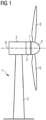
- Fig. 1 shows a wind turbine 1.
- the wind turbine 1 comprises a nacelle 3 and a tower 2.
- the nacelle 3 is mounted at the top of the tower 2.
- the nacelle 3 is mounted rotatable with regard to the tower 2 by means of a yaw bearing.
- the axis of rotation of the nacelle 3 with regard to the tower 2 is referred to as the yaw axis.
- the wind turbine 1 also comprises a rotor 4 with three rotor blades 6 (of which two rotor blades 6 are depicted in Fig. 1 ).
- the rotor 4 is mounted rotatable with regard to the nacelle 3 by means of a main bearing 7.
- the rotor 4 is mounted rotatable about a rotation axis 8 (rotor axis).
- the wind turbine 1 furthermore comprises a generator 5.
- the generator 5 in turn comprises a rotor connecting the generator 5 with the rotor 4. If the rotor 4 is connected directly to the generator 5, the wind turbine 1 is referred to as a gearless, direct-driven wind turbine. Such a generator 5 is referred as direct drive generator 5.
- the rotor 4 may also be connected to the generator 5 via a gear box.
- This type of wind turbine 1 is referred to as a geared wind turbine.
- the present invention is suitable for both types of wind turbines 1.
- the generator 5 is accommodated within the nacelle 3.
- the generator 5 is arranged and prepared for converting the rotational energy from the rotor 4 into electrical energy in the shape of an AC power.
- the blades 6 can be pitched, i.e., rotated about a longitudinal axis of the blade 6.
- the wind turbine 1 is configured to collectively pitch all blades 6 by a collective pitching degree and to individually pitch each blade 6 by an individual pitching degree.
- a method of pitching blades of the wind turbine 1 comprises steps of determining a collective pitch reference for all blades 6, determining an individual pitch reference for each blade 6 and determining whether at least one blade 6 is unable to reach the individual pitch reference. If it is determined that at least one blade 6 is unable to reach its individual pitch reference, the individual pitch reference for this blade 6 is prioritized against the collective pitch reference.
- each blade 6 is configured to be pitched towards a production direction, in which the power for driving the generator is increased, and towards a stop direction, in which the power for driving the generator is decreased. If it is determined that the at least one blade 6 is unable to reach its individual pitch reference, the collective pitch reference is shifted towards the stop direction.
- Fig. 2 shows a flowchart of a step of prioritizing an individual pitch reference against a collective pitch reference according to another embodiment.
- the wind turbine 1 comprises three blades 6.
- a position, i.e., a pitch angle, of a first blade 6 is detected and input into a block 41.
- An individual pitch reference for the first blade 6 is input from a block 12 into the block 41.
- a tracking error of the first blade 6 is calculated as a difference between the individual pitch reference for the first blade 6 and the actual position of the first blade 6.
- a position, i.e., a pitch angle, of a second blade 6 is detected and input into a block 42.
- An individual pitch reference for the second blade 6 is input from a block 22 into the block 42.
- a tracking error of the second blade 6 is calculated as a difference between the individual pitch reference for the second blade 6 and the actual position of the second blade 6.
- a position, i.e., a pitch angle, of a third blade 6 is detected and input into a block 43.
- An individual pitch reference for the third blade 6 is input from a block 32 into the block 43.
- a tracking error of the third blade 6 is calculated as a difference between the individual pitch reference for the third blade 6 and the actual position of the third blade 6.
- the three tracking errors of the three blades 6 are input into a block 50, where a maximum of the three tracking errors is determined.
- the determined maximum tracking error is input from the block 50 into a block 60, where the determined maximum tracking error is converted to a corrective reference offset.
- the corrective reference offset is input from the block 60 into a block 80.
- a collective pitch reference for all blades 6 is input from a block 70 into the block 80.
- the corrective reference offset and the collective pitch reference are added to obtain a corrected collective pitch reference in a block 90.
- the blades 6 are pitched with the individual pitch references and the thus corrected collective pitch reference.
- the step of prioritizing the individual pitch reference for the respective blade 6 against the collective pitch reference comprises a step of weighting the individual pitch reference for this blade 6 with a first weight, and a step of weighting the collective pitch reference with a second weight.
- the first weight is larger than the second weight.
- One of the first and second weights can be 1 by default.
- at least one of the first weight and the second weight is a function of a tracking error of the blade 6, which is a difference between the individual pitch reference and the actual blade pitch position of the blade 6.
- the at least one blade 6 is unable to reach its individual pitch reference. For example, it can be determined that the at least one blade 6 is unable to reach its individual pitch reference, if a tracking error of each blade 6, which is a difference between the individual pitch reference and the actual blade pitch position of each blade 6, or a difference between an individual pitching speed reference of the blade 6 and an actual pitching speed of the blade 6, exceeds a predetermined threshold value.
- Fig. 3 shows pitching amplitudes in an individual pitch control according to the prior art.
- the solid lines indicate the amplitudes of the individual pitch control for each of the three blades 6.
- the dotted line shows the collective pitch reference which in this example is constant/unchanged.
- the amplitudes in the individual pitch control in the middle area are limited by lack of a pitch force. All three blades 6 are unable to reach their individual pitch references.
- Fig. 4 shows pitching amplitudes in an individual pitch control according to an embodiment of the present invention.
- the solid lines indicate the amplitudes of the individual pitch control for each of the three blades 6.
- the dotted line shows the collective pitch reference.
- the control strategy of the present invention shows the solution where the collective pitch reference is lowered to preserve the amplitudes of the individual pitch control.
- the amplitudes of the individual pitch control are reached/maintained, and therefore the load targets in the individual pitch control in this situation are kept under control, whereas in prior art of Fig. 3 , the effectiveness of the individual pitch control is reduced, and loads are increased.
Landscapes
- Engineering & Computer Science (AREA)
- Life Sciences & Earth Sciences (AREA)
- Sustainable Development (AREA)
- Sustainable Energy (AREA)
- Chemical & Material Sciences (AREA)
- Combustion & Propulsion (AREA)
- Mechanical Engineering (AREA)
- General Engineering & Computer Science (AREA)
- Physics & Mathematics (AREA)
- Fluid Mechanics (AREA)
- Wind Motors (AREA)
Abstract
It is described a method and a device for pitching blades of a wind turbine (1). The wind turbine (1) is configured to collectively pitch all blades (6) by a collective pitching degree and to individually pitch each blade (6) by an individual pitching degree. If it is determined that at least one blade (6) is unable to reach its individual pitch reference, the individual pitch reference for this blade (6) is prioritized against the collective pitch reference.
Description
- The present invention relates to a method and a device for individually pitching blades of a wind turbine. A conventional wind turbine comprises a rotor having a plurality of rotor blades, wherein each blade is configured to be pitched by a pitch angle about a pitch axis of the blade, the rotor is mounted to a nacelle to rotate about a rotation axis with a rotor speed to drive a generator for producing electrical energy, and the nacelle is mounted to a tower. Some wind turbines are configured to collectively pitch all blades by a collective pitching degree and to individually pitch each blade by an individual pitching degree.
- The pitch position shall be equal to (or very close to) the pitch reference. This is a crucial operation as loads on the turbine are dependent on the pitch position. Under certain conditions, an individual pitch control (IPC) is used to lower the loads due to e.g., high yaw misalignment, high shear, wake situations. This control adds typically a 1P component (a sinusoid with the period time of a single full rotation) to the collective pitch reference. This 1P component is dependent on the azimuth angle of the rotor, and the phase of this sinusoid is shifted by 120 degrees between each of the blades (in a wind turbine having three blades). By doing so, it increases thrust on one side of the rotor and relieves thrust on the other side. This way unbalanced load from yaw errors or high shear can be balanced out or lower the impact on the mechanical components. It keeps the average of the collective pitch position and keeps the desired power production.
- If in these situations the pitch reference is not adhered to the blade positions, the loads from these sources will increase, with a risk of overloading the yaw system or hub bending.
- There are certain situations where the actual pitch position cannot reach the pitch reference, for example, when there are large forces on the blade due to the wind conditions that the pitch system cannot overcome, when the pitch force is low due to low hydraulic pressure, and/or when the pitch in speed is lower than the pitch speed demanded by the individual pitching. These conditions can hardly be handled by conventional controllers, and there are risks of overloading the mechanical components.
- There may be a need for a method and a device for individually pitching blades of a wind turbine, which can reduce the loads on the blades. This need may be met by the subject matters according to the independent claims. The present invention is further developed as set forth in the dependent claims.
- According to a first aspect of the invention, a method of pitching blades of a wind turbine is provided. The wind turbine comprises a rotor having a plurality of rotor blades, each blade being configured to be pitched by a pitch angle about a pitch axis of the blade, the rotor being mounted to a nacelle to rotate about a rotation axis with a rotor speed to drive a generator for producing electrical energy, the nacelle being mounted tower to rotate about a yaw axis, wherein the wind turbine is configured to collectively pitch all blades by a collective pitching degree and to individually pitch each blade by an individual pitching degree. The method comprising the following steps: determining a collective pitch reference for all blades; determining an individual pitch reference for each blade; determining whether at least one blade is unable to reach the individual pitch reference. If it is determined that at least one blade is unable to reach its individual pitch reference, the individual pitch reference for this blade is prioritized against the collective pitch reference.
- The loads, which are lowered using the individual pitch control, largely depend on the amplitude of the individual pitch control, the phase and to a small extent on the collective pitch reference. This novel control strategy prioritizes the pitch reference of the individual pitch control over the collective pitch reference in case the pitch system cannot provide both. By this way, excessive loads on the turbine components can be avoided.
- In an embodiment, each blade is configured to be pitched towards a production direction, in which the power for driving the generator is increased, and towards a stop direction, in which the power for driving the generator is decreased. If it is determined that the at least one blade is unable to reach its individual pitch reference, the individual pitch reference for this blade is prioritized against the collective pitch reference by shifting the collective pitch reference towards the stop direction. The inventors found out that, when the pitch force is not sufficient for individual pitch control, this usually happens in the direction towards a production direction. Therefore, this embodiment shifts the collective pitch reference towards the stop direction. Although the present invention generally works in both directions, there is a particular advantage when pitching of the blades will be limited towards the production direction, wherein a corrective reference offset, for example that of the following embodiment, is added to the collective pitch reference which is then shifted towards the stop direction.
- In an embodiment, the step of prioritizing the individual pitch reference for this blade against the collective pitch reference comprises a step of calculating a tracking error of each blade, which is a difference between the individual pitch reference and the actual blade pitch position of each blade; a step of determining a maximum of the calculated tracking errors of the blades; a step of converting the maximum to a corrective reference offset; a step of adding the corrective reference offset to the collective pitch reference to obtain a corrected collective pitch reference; and a step of pitching the blades with the individual pitch references and the corrected collective pitch reference. In this embodiment, the maximum from all tracking errors is taken and not the summation, as the blade with the highest tracking error will provide a sufficient corrective reference offset to the collective pitch reference for all blades that are impacted. If the at least one blade is unable to reach the individual pitch reference, for example if the at least one blade is being unable to be pitched towards the production direction of power production to provide the desired amplitude of the individual pitch control around the collective pitch reference, the collective pitch reference can be moved to stop by a portion of (or the full amplitude of) the (pitch) tracking error to preserve the amplitude of the individual pitch control.
- In an embodiment, the step of converting the maximum to the corrective reference offset is made by use of a look-up-table (LUT), where the tracking error caused by an expected system inertia is tolerated without modifying the collective pitch reference by the corrective reference offset. Thereby, the step of prioritizing the individual pitch reference is not performed in case of tracking errors, which are caused by inertia e.g., of the blades and are part of a normal operation.
- In an embodiment, the step of prioritizing the individual pitch reference for this blade against the collective pitch reference comprises a step of weighting the individual pitch reference for this blade with a first weight; and a step of weighting the collective pitch reference with a second weight. The first weight is larger than the second weight so that the individual pitch reference for this blade is prioritized against the collective pitch reference. However, at least one of the first and second weights can have the
value 1 by default (which means a default weight of 1). - Preferably, at least one of the first weight and the second weight is a function of a tracking error of the blade, which is a difference between the individual pitch reference and the actual blade pitch position of the blade, wherein, e.g., the larger the tracking error is, the larger a ratio between the first weight and the second weight is. However, it may also be a constant weight above a certain tracking error, where it does not increase further.
- In an embodiment, it is determined that the at least one blade is unable to reach its individual pitch reference, if a tracking error of each blade, which is a difference between the individual pitch reference and the actual blade pitch position of each blade, or a difference between an individual pitching speed reference of the blade and an actual pitching speed of the blade, exceeds a predetermined threshold value.
- According to a second aspect of the invention, a device for pitching blades of a wind turbine is provided. The wind turbine comprises a rotor having a plurality of rotor blades, each blade being configured to be pitched by a pitch angle about a pitch axis of the blade, the rotor being mounted to a nacelle to rotate about a rotation axis with a rotor speed to drive a generator for producing electrical energy, the nacelle being mounted tower to rotate about a yaw axis. The device is configured to collectively pitch all blades by a collective pitching degree and to individually pitch each blade by an individual pitching degree. The device comprises a first determining unit configured to determine a collective pitch reference for all blades; a second determining unit configured to determine an individual pitch reference for each blade; a third determining unit configured to determine whether at least one blade is unable to reach the individual pitch reference; and a prioritizing unit configured to prioritize the individual pitch reference for this blade against the collective pitch reference, if it is determined by the third determining unit that at least one blade is unable to reach its individual pitch reference.
- It has to be noted that embodiments of the invention have been described with reference to different subject matters. In particular, some embodiments have been described with reference to apparatus type claims whereas other embodiments have been described with reference to method type claims. However, a person skilled in the art will gather from the above and the following description that, unless other notified, in addition to any combination of features belonging to one type of subject matter also any combination between features relating to different subject matters, in particular between features of the apparatus type claims and features of the method type claims is considered as to be disclosed with this application.
- The aspects defined above and further aspects of the present invention are apparent from the examples of embodiment to be described hereinafter and are explained with reference to the examples of embodiment. The invention will be described in more detail hereinafter with reference to examples of embodiment but to which the invention is not limited.
- Fig. 1
- shows a wind turbine and the different elements thereof;
- Fig. 2
- shows a flowchart of a step of prioritizing an individual pitch reference against a collective pitch reference according to an embodiment;
- Fig. 3
- shows pitching amplitudes in an individual pitch control according to the prior art; and
- Fig. 4
- shows pitching amplitudes in an individual pitch control according to an embodiment of the present invention.
- The illustrations in the drawings are schematically. It is noted that in different figures, similar or identical elements are provided with the same reference signs.
-
Fig. 1 shows awind turbine 1. Thewind turbine 1 comprises anacelle 3 and atower 2. Thenacelle 3 is mounted at the top of thetower 2. Thenacelle 3 is mounted rotatable with regard to thetower 2 by means of a yaw bearing. The axis of rotation of thenacelle 3 with regard to thetower 2 is referred to as the yaw axis. - The
wind turbine 1 also comprises a rotor 4 with three rotor blades 6 (of which tworotor blades 6 are depicted inFig. 1 ). The rotor 4 is mounted rotatable with regard to thenacelle 3 by means of a main bearing 7. The rotor 4 is mounted rotatable about a rotation axis 8 (rotor axis). - The
wind turbine 1 furthermore comprises agenerator 5. Thegenerator 5 in turn comprises a rotor connecting thegenerator 5 with the rotor 4. If the rotor 4 is connected directly to thegenerator 5, thewind turbine 1 is referred to as a gearless, direct-driven wind turbine. Such agenerator 5 is referred asdirect drive generator 5. As an alternative, the rotor 4 may also be connected to thegenerator 5 via a gear box. This type ofwind turbine 1 is referred to as a geared wind turbine. The present invention is suitable for both types ofwind turbines 1. - The
generator 5 is accommodated within thenacelle 3. Thegenerator 5 is arranged and prepared for converting the rotational energy from the rotor 4 into electrical energy in the shape of an AC power. - The
blades 6 can be pitched, i.e., rotated about a longitudinal axis of theblade 6. Thewind turbine 1 is configured to collectively pitch allblades 6 by a collective pitching degree and to individually pitch eachblade 6 by an individual pitching degree. A method of pitching blades of thewind turbine 1 comprises steps of determining a collective pitch reference for allblades 6, determining an individual pitch reference for eachblade 6 and determining whether at least oneblade 6 is unable to reach the individual pitch reference. If it is determined that at least oneblade 6 is unable to reach its individual pitch reference, the individual pitch reference for thisblade 6 is prioritized against the collective pitch reference. - Prioritizing the individual pitch reference against the collective pitch reference can be made in different ways. In an embodiment, each
blade 6 is configured to be pitched towards a production direction, in which the power for driving the generator is increased, and towards a stop direction, in which the power for driving the generator is decreased. If it is determined that the at least oneblade 6 is unable to reach its individual pitch reference, the collective pitch reference is shifted towards the stop direction. -
Fig. 2 shows a flowchart of a step of prioritizing an individual pitch reference against a collective pitch reference according to another embodiment. In this embodiment, thewind turbine 1 comprises threeblades 6. In ablock 11, a position, i.e., a pitch angle, of afirst blade 6 is detected and input into ablock 41. An individual pitch reference for thefirst blade 6 is input from ablock 12 into theblock 41. In theblock 41, a tracking error of thefirst blade 6 is calculated as a difference between the individual pitch reference for thefirst blade 6 and the actual position of thefirst blade 6. - The same is done for the second and
third blades 6. In ablock 21, a position, i.e., a pitch angle, of asecond blade 6 is detected and input into ablock 42. An individual pitch reference for thesecond blade 6 is input from ablock 22 into theblock 42. In theblock 42, a tracking error of thesecond blade 6 is calculated as a difference between the individual pitch reference for thesecond blade 6 and the actual position of thesecond blade 6. In ablock 31, a position, i.e., a pitch angle, of athird blade 6 is detected and input into ablock 43. An individual pitch reference for thethird blade 6 is input from ablock 32 into theblock 43. In theblock 43, a tracking error of thethird blade 6 is calculated as a difference between the individual pitch reference for thethird blade 6 and the actual position of thethird blade 6. - The three tracking errors of the three
blades 6 are input into ablock 50, where a maximum of the three tracking errors is determined. The determined maximum tracking error is input from theblock 50 into ablock 60, where the determined maximum tracking error is converted to a corrective reference offset. - The corrective reference offset is input from the
block 60 into ablock 80. In addition, a collective pitch reference for allblades 6 is input from ablock 70 into theblock 80. In theblock 80, the corrective reference offset and the collective pitch reference are added to obtain a corrected collective pitch reference in ablock 90. Eventually, theblades 6 are pitched with the individual pitch references and the thus corrected collective pitch reference. - In another embodiment, the step of prioritizing the individual pitch reference for the
respective blade 6 against the collective pitch reference comprises a step of weighting the individual pitch reference for thisblade 6 with a first weight, and a step of weighting the collective pitch reference with a second weight. The first weight is larger than the second weight. One of the first and second weights can be 1 by default. In a modified embodiment, at least one of the first weight and the second weight is a function of a tracking error of theblade 6, which is a difference between the individual pitch reference and the actual blade pitch position of theblade 6. - There are many ways to determine that the at least one
blade 6 is unable to reach its individual pitch reference. For example, it can be determined that the at least oneblade 6 is unable to reach its individual pitch reference, if a tracking error of eachblade 6, which is a difference between the individual pitch reference and the actual blade pitch position of eachblade 6, or a difference between an individual pitching speed reference of theblade 6 and an actual pitching speed of theblade 6, exceeds a predetermined threshold value. -
Fig. 3 shows pitching amplitudes in an individual pitch control according to the prior art. The solid lines indicate the amplitudes of the individual pitch control for each of the threeblades 6. The dotted line shows the collective pitch reference which in this example is constant/unchanged. The amplitudes in the individual pitch control in the middle area are limited by lack of a pitch force. All threeblades 6 are unable to reach their individual pitch references. -
Fig. 4 shows pitching amplitudes in an individual pitch control according to an embodiment of the present invention. The solid lines indicate the amplitudes of the individual pitch control for each of the threeblades 6. The dotted line shows the collective pitch reference. The control strategy of the present invention shows the solution where the collective pitch reference is lowered to preserve the amplitudes of the individual pitch control. The amplitudes of the individual pitch control are reached/maintained, and therefore the load targets in the individual pitch control in this situation are kept under control, whereas in prior art ofFig. 3 , the effectiveness of the individual pitch control is reduced, and loads are increased. - It should be noted that the term "comprising" does not exclude other elements or steps and "a" or "an" does not exclude a plurality. Also elements described in association with different embodiments may be combined. It should also be noted that reference signs in the claims should not be construed as limiting the scope of the claims.
Claims (8)
- A method of pitching blades of a wind turbine (1), the wind turbine (1) comprising a rotor (4) having a plurality of rotor blades (6), each blade (6) being configured to be pitched by a pitch angle about a pitch axis of the blade (6), the rotor (4) being mounted to a nacelle (3) to rotate about a rotation axis (8) with a rotor speed to drive a generator (5) for producing electrical energy, the nacelle (3) being mounted to a tower (2), wherein the wind turbine (1) is configured to collectively pitch all blades (6) by a collective pitching degree and to individually pitch each blade (6) by an individual pitching degree, the method comprising the following steps:determining a collective pitch reference for all blades (6) ;determining an individual pitch reference for each blade (6) ;determining whether at least one blade (6) is unable to reach the individual pitch reference;if it is determined that at least one blade (6) is unable to reach its individual pitch reference, prioritizing the individual pitch reference for this blade (6) against the collective pitch reference.
- The method according to the preceding claim, whereineach blade (6) is configured to be pitched towards a production direction, in which the power for driving the generator is increased, and towards a stop direction, in which the power for driving the generator is decreased; andwherein, if it is determined that the at least one blade (6) is unable to reach its individual pitch reference, the individual pitch reference for this blade (6) is prioritized against the collective pitch reference by shifting the collective pitch reference towards the stop direction.
- The method according to any one of the preceding claims, wherein
the step of prioritizing the individual pitch reference for this blade (6) against the collective pitch reference comprises:calculating a tracking error of each blade (6), which is a difference between the individual pitch reference and the actual blade pitch position of each blade (6);determining a maximum of the calculated tracking errors of the blades (6);converting the maximum to a corrective reference offset;adding the corrective reference offset to the collective pitch reference to obtain a corrected collective pitch reference; andpitching the blades (6) with the individual pitch references and the corrected collective pitch reference. - The method according to the preceding claim, wherein
the step of converting the maximum to the corrective reference offset is made by use of a look-up-table, where the tracking error caused by an expected system inertia is tolerated without modifying the collective pitch reference by the corrective reference offset. - The method according to any one of the preceding claims, wherein
the step of prioritizing the individual pitch reference for this blade (6) against the collective pitch reference comprises:weighting the individual pitch reference for this blade (6) with a first weight;weighting the collective pitch reference with a second weight;wherein the first weight is larger than the second weight. - The method according to the preceding claim, whereinat least one of the first weight and the second weight is a function of a tracking error of the blade (6), which is a difference between the individual pitch reference and the actual blade pitch position of the blade (6);wherein, the larger the tracking error is, the larger a ratio between the first weight and the second weight is.
- The method according to any one of the preceding claims, wherein
it is determined that the at least one blade (6) is unable to reach its individual pitch reference, if a tracking error of each blade (6), which is a difference between the individual pitch reference and the actual blade pitch position of each blade (6), or a difference between an individual pitching speed reference of the blade (6) and an actual pitching speed of the blade (6), exceeds a predetermined threshold value. - A device for pitching blades of a wind turbine (1), the wind turbine (1) comprising a rotor (4) having a plurality of rotor blades (6), each blade (6) being configured to be pitched by a pitch angle about a pitch axis of the blade (6), the rotor (4) being mounted to a nacelle (3) to rotate about a rotation axis (8) with a rotor speed to drive a generator (5) for producing electrical energy, the nacelle (3) being mounted to a tower (2), wherein the device is configured to collectively pitch all blades (6) by a collective pitching degree and to individually pitch each blade (6) by an individual pitching degree, the device comprising:a first determining unit configured to determine a collective pitch reference for all blades (6);a second determining unit configured to determine an individual pitch reference for each blade (6);a third determining unit configured to determine whether at least one blade (6) is unable to reach the individual pitch reference; anda prioritizing unit configured to prioritize the individual pitch reference for this blade (6) against the collective pitch reference, if it is determined by the third determining unit that at least one blade (6) is unable to reach its individual pitch reference.
Priority Applications (6)
| Application Number | Priority Date | Filing Date | Title |
|---|---|---|---|
| EP22151367.4A EP4212718A1 (en) | 2022-01-13 | 2022-01-13 | Method and device for individually pitching blades of a wind turbine |
| PCT/EP2022/083804 WO2023134916A1 (en) | 2022-01-13 | 2022-11-30 | Method and device for individually pitching blades of a wind turbine |
| DK22823449.8T DK4463625T3 (en) | 2022-01-13 | 2022-11-30 | Method and device for individually pitching blades of a wind turbine |
| US18/727,805 US12503999B2 (en) | 2022-01-13 | 2022-11-30 | Method and device for individually pitching blades of a wind turbine |
| EP22823449.8A EP4463625B1 (en) | 2022-01-13 | 2022-11-30 | Method and device for individually pitching blades of a wind turbine |
| CN202280088785.5A CN118541542A (en) | 2022-01-13 | 2022-11-30 | Method and apparatus for individually pitching blades of a wind turbine |
Applications Claiming Priority (1)
| Application Number | Priority Date | Filing Date | Title |
|---|---|---|---|
| EP22151367.4A EP4212718A1 (en) | 2022-01-13 | 2022-01-13 | Method and device for individually pitching blades of a wind turbine |
Publications (1)
| Publication Number | Publication Date |
|---|---|
| EP4212718A1 true EP4212718A1 (en) | 2023-07-19 |
Family
ID=79601895
Family Applications (2)
| Application Number | Title | Priority Date | Filing Date |
|---|---|---|---|
| EP22151367.4A Withdrawn EP4212718A1 (en) | 2022-01-13 | 2022-01-13 | Method and device for individually pitching blades of a wind turbine |
| EP22823449.8A Active EP4463625B1 (en) | 2022-01-13 | 2022-11-30 | Method and device for individually pitching blades of a wind turbine |
Family Applications After (1)
| Application Number | Title | Priority Date | Filing Date |
|---|---|---|---|
| EP22823449.8A Active EP4463625B1 (en) | 2022-01-13 | 2022-11-30 | Method and device for individually pitching blades of a wind turbine |
Country Status (5)
| Country | Link |
|---|---|
| US (1) | US12503999B2 (en) |
| EP (2) | EP4212718A1 (en) |
| CN (1) | CN118541542A (en) |
| DK (1) | DK4463625T3 (en) |
| WO (1) | WO2023134916A1 (en) |
Citations (3)
| Publication number | Priority date | Publication date | Assignee | Title |
|---|---|---|---|---|
| EP2329141A2 (en) * | 2008-08-29 | 2011-06-08 | Vestas Wind Systems A/S | Pitch control system |
| US20110229300A1 (en) * | 2010-03-16 | 2011-09-22 | Stichting Energieonderzoek Centrum Nederland | Apparatus and method for individual pitch control in wind turbines |
| EP3892850A1 (en) * | 2020-04-08 | 2021-10-13 | General Electric Renovables España S.L. | System and method for mitigating loads acting on a rotor blade of a wind turbine |
Family Cites Families (3)
| Publication number | Priority date | Publication date | Assignee | Title |
|---|---|---|---|---|
| US8430632B2 (en) * | 2011-12-22 | 2013-04-30 | General Electric Company | System and method for pitching a rotor blade in a wind turbine |
| DE102013204492A1 (en) * | 2013-03-14 | 2014-09-18 | Senvion Se | Method and system for monitoring a single blade adjustment of a wind energy plant |
| CN112696317B (en) * | 2019-10-22 | 2025-04-15 | 通用电气可再生能源西班牙有限公司 | System and method for controlling a wind turbine based on a collective pitch offset |
-
2022
- 2022-01-13 EP EP22151367.4A patent/EP4212718A1/en not_active Withdrawn
- 2022-11-30 US US18/727,805 patent/US12503999B2/en active Active
- 2022-11-30 EP EP22823449.8A patent/EP4463625B1/en active Active
- 2022-11-30 CN CN202280088785.5A patent/CN118541542A/en active Pending
- 2022-11-30 DK DK22823449.8T patent/DK4463625T3/en active
- 2022-11-30 WO PCT/EP2022/083804 patent/WO2023134916A1/en not_active Ceased
Patent Citations (3)
| Publication number | Priority date | Publication date | Assignee | Title |
|---|---|---|---|---|
| EP2329141A2 (en) * | 2008-08-29 | 2011-06-08 | Vestas Wind Systems A/S | Pitch control system |
| US20110229300A1 (en) * | 2010-03-16 | 2011-09-22 | Stichting Energieonderzoek Centrum Nederland | Apparatus and method for individual pitch control in wind turbines |
| EP3892850A1 (en) * | 2020-04-08 | 2021-10-13 | General Electric Renovables España S.L. | System and method for mitigating loads acting on a rotor blade of a wind turbine |
Also Published As
| Publication number | Publication date |
|---|---|
| EP4463625B1 (en) | 2025-09-03 |
| DK4463625T3 (en) | 2025-11-03 |
| US20250092855A1 (en) | 2025-03-20 |
| CN118541542A (en) | 2024-08-23 |
| US12503999B2 (en) | 2025-12-23 |
| EP4463625A1 (en) | 2024-11-20 |
| WO2023134916A1 (en) | 2023-07-20 |
Similar Documents
| Publication | Publication Date | Title |
|---|---|---|
| US10612520B2 (en) | Rotational positioning system in a wind turbine | |
| EP2067988B1 (en) | Apparatus and method for reducing asymmetric rotor loads in wind turbine shutdown | |
| EP2037119B1 (en) | Controller for wind turbine yaw system and method for reducing the loads acting on such a yaw system | |
| EP2108825B1 (en) | System and method for reducing rotor loads in a wind turbine upon detection of blade-pitch failure and loss of counter-torque | |
| US8215906B2 (en) | Variable tip speed ratio tracking control for wind turbines | |
| EP3568589B1 (en) | Method for load reduction on wind turbine blade pitch bearings | |
| US8154143B2 (en) | Wind energy converter comprising a superposition gear | |
| EP1612412B1 (en) | Storm control for horizontal axis wind turbine | |
| EP2737205B1 (en) | A method of yawing a rotor of a wind turbine | |
| EP2500562A2 (en) | Methods and systems for alleviating the loads generated in wind turbines by wind asymmetries | |
| EP2484901A2 (en) | A wind turbine and an associated control method | |
| WO2011157271A2 (en) | A method and control unit for controlling a wind turbine in dependence on loading experienced by the wind turbine | |
| EP3985247A1 (en) | Method of controlling a wind turbine | |
| KR102042259B1 (en) | Wind-Electric Power Generation System and Driving Stop Method Thereof | |
| EP4133176B1 (en) | Device and method of controlling blade instabilities of a wind turbine to avoid blade fluttering | |
| EP4463625B1 (en) | Method and device for individually pitching blades of a wind turbine | |
| JP7174682B2 (en) | Wind power generator and its stopping method | |
| CN115667701B (en) | Devices and methods for controlling the operation of wind turbines to reduce loads during yaw misalignment | |
| US20240271601A1 (en) | Single-Point-Mooring Wind Turbine with Two Wind Energy Conversion Units Each Having a Rotor | |
| EP4134543A1 (en) | Method of stopping an operation of a floating wind turbine | |
| US12092079B2 (en) | Wind turbine operation in extreme wind conditions | |
| CN120969049A (en) | Typhoon-resistance control method and floating wind turbine generator |
Legal Events
| Date | Code | Title | Description |
|---|---|---|---|
| PUAI | Public reference made under article 153(3) epc to a published international application that has entered the european phase |
Free format text: ORIGINAL CODE: 0009012 |
|
| STAA | Information on the status of an ep patent application or granted ep patent |
Free format text: STATUS: THE APPLICATION HAS BEEN PUBLISHED |
|
| AK | Designated contracting states |
Kind code of ref document: A1 Designated state(s): AL AT BE BG CH CY CZ DE DK EE ES FI FR GB GR HR HU IE IS IT LI LT LU LV MC MK MT NL NO PL PT RO RS SE SI SK SM TR |
|
| STAA | Information on the status of an ep patent application or granted ep patent |
Free format text: STATUS: THE APPLICATION IS DEEMED TO BE WITHDRAWN |
|
| 18D | Application deemed to be withdrawn |
Effective date: 20240120 |