EP4212662A1 - Washer-dryer comprising a fluff filter in the tub and process for operating the washer-dryer - Google Patents
Washer-dryer comprising a fluff filter in the tub and process for operating the washer-dryer Download PDFInfo
- Publication number
- EP4212662A1 EP4212662A1 EP22213393.6A EP22213393A EP4212662A1 EP 4212662 A1 EP4212662 A1 EP 4212662A1 EP 22213393 A EP22213393 A EP 22213393A EP 4212662 A1 EP4212662 A1 EP 4212662A1
- Authority
- EP
- European Patent Office
- Prior art keywords
- tub
- drum
- washer
- dryer
- air
- Prior art date
- Legal status (The legal status is an assumption and is not a legal conclusion. Google has not performed a legal analysis and makes no representation as to the accuracy of the status listed.)
- Granted
Links
Images


Classifications
-
- D—TEXTILES; PAPER
- D06—TREATMENT OF TEXTILES OR THE LIKE; LAUNDERING; FLEXIBLE MATERIALS NOT OTHERWISE PROVIDED FOR
- D06F—LAUNDERING, DRYING, IRONING, PRESSING OR FOLDING TEXTILE ARTICLES
- D06F25/00—Washing machines with receptacles, e.g. perforated, having a rotary movement, e.g. oscillatory movement, the receptacle serving both for washing and for centrifugally separating water from the laundry and having further drying means, e.g. using hot air
-
- D—TEXTILES; PAPER
- D06—TREATMENT OF TEXTILES OR THE LIKE; LAUNDERING; FLEXIBLE MATERIALS NOT OTHERWISE PROVIDED FOR
- D06F—LAUNDERING, DRYING, IRONING, PRESSING OR FOLDING TEXTILE ARTICLES
- D06F35/00—Washing machines, apparatus, or methods not otherwise provided for
- D06F35/005—Methods for washing, rinsing or spin-drying
- D06F35/008—Methods for washing, rinsing or spin-drying for disinfecting the tub or the drum
-
- D—TEXTILES; PAPER
- D06—TREATMENT OF TEXTILES OR THE LIKE; LAUNDERING; FLEXIBLE MATERIALS NOT OTHERWISE PROVIDED FOR
- D06F—LAUNDERING, DRYING, IRONING, PRESSING OR FOLDING TEXTILE ARTICLES
- D06F37/00—Details specific to washing machines covered by groups D06F21/00 - D06F25/00
- D06F37/26—Casings; Tubs
- D06F37/267—Tubs specially adapted for mounting thereto components or devices not provided for in preceding subgroups
-
- D—TEXTILES; PAPER
- D06—TREATMENT OF TEXTILES OR THE LIKE; LAUNDERING; FLEXIBLE MATERIALS NOT OTHERWISE PROVIDED FOR
- D06F—LAUNDERING, DRYING, IRONING, PRESSING OR FOLDING TEXTILE ARTICLES
- D06F58/00—Domestic laundry dryers
- D06F58/20—General details of domestic laundry dryers
- D06F58/22—Lint collecting arrangements
-
- D—TEXTILES; PAPER
- D06—TREATMENT OF TEXTILES OR THE LIKE; LAUNDERING; FLEXIBLE MATERIALS NOT OTHERWISE PROVIDED FOR
- D06F—LAUNDERING, DRYING, IRONING, PRESSING OR FOLDING TEXTILE ARTICLES
- D06F58/00—Domestic laundry dryers
- D06F58/20—General details of domestic laundry dryers
- D06F58/26—Heating arrangements, e.g. gas heating equipment
Definitions
- the invention relates to a washer-dryer, including a tub in which a drum for receiving laundry items is rotatably provided; a process air circuit for passing an air flow of process air through the drum comprising a blower for driving the air flow; an air heating device for heating the process air before the process air enters the drum; and a fluff filter.
- the invention also relates to a process for operating the washer-dryer.
- the outlet for process air from the tub is located often in the rear part of the tub.
- the process air is then guided to the evaporator of the heat pump through an air duct.
- the filter is integrated in the air duct and additionally a cleaning system which is generally based on flushing water is involved.
- the publication EP 3 825 450 A1 discloses a laundry treating appliance with a filter.
- a combination washer/dryer comprising: a tub at least partially defining a tub interior with a tub access opening; a rotatable drum located within the tub interior and at least partially defining a treating chamber with a treating chamber access opening; a drying airduct having an inlet formed in the tub and defining a cross-sectional area at the inlet; and a filter having a front face overlying the inlet and having a surface area greater than the cross-sectional area.
- Fig. 3A a cross-sectional side-view of the filter of the combination washing and drying machine is shown.
- the filter can be positioned between the drum and the tub at the inlet of the drying air duct. It can include a seat portion which can extend into at least a portion of the drying air duct past the inlet.
- the present invention provides a washer-dryer which allows an improved filtering of the process air after it has been used for drying laundry items.
- the use of the fluff filter should be improved.
- the cleaning of the fluff filter should be improved such that for example fluff can be dealt with in a better way and time intervals between cleaning steps of the fluff filter can become shorter.
- a further object was the provision of a process for operating this dryer.
- the invention is thus directed to a washer-dryer including a tub in which a drum for receiving laundry items is rotatably provided; a process air circuit for passing an air flow of process air through the drum comprising a blower for driving the air flow; an air heating device for heating the process air before the process air enters the drum; and a fluff filter; wherein the fluff filter is provided inside the tub between the tub and the drum.
- the air heating device is selected from the group consisting of an electric resistance heater and a condenser of a heat pump, or a combination thereof.
- the air heating device is the condenser of a heat pump.
- a heat pump circuit used in a preferred embodiment of the present invention includes a refrigerant channel for circulating a refrigerant, the condenser as a heat source, the evaporator as a heat sink, an expansion device for expanding the refrigerant flow, and a compressor for driving and compressing the refrigerant, the refrigerant circulating sequentially through the compressor, the condenser, the expansion device and the evaporator.
- the refrigerant In the heat pump circuit the refrigerant is circulated and thereby cyclically compressed and expanded as well as cooled and heated, on purpose of absorbing heat in the evaporator by evaporating the refrigerant at low pressure, and releasing heat in the condenser by condensing the refrigerant at high pressure.
- the washer-dryer comprises a control device for controlling operation of the washer-dryer.
- the expansion device is usually a variable valve operably connected to the control device.
- Such operation may be of a switching type, whereby the valve is switched between an open position for recirculating a part of the refrigerant and a closed position which cuts off any recirculation.
- Such operation may allow varying the amount of refrigerant which is recirculated, either stepwise or continuously.
- the fluff filter is provided on or close to an inner wall of the tub.
- the inner wall is a rear wall of the tub.
- the shape of the fluff filter is not especially limited. In any way, it is preferred that the fluff filter is coaxial with the rotation axis of the drum.
- the fluff filter has essentially the form of a circular ring that is placed on the rear tub wall or separated by a small gap from the rear tub wall.
- a shape of the fluff filter can be considered to be a donut-shape in the interior side of tub, in particular at the rear part thereof.
- One particular implementation could be one where there is a fluff filter section covering around 300° of the circumference. This section of filter could be dimensioned as desired according to the needs.
- the outlet hole (for process air which is to enter the exhaust air duct) is preferably designed to be protected against washing/spinning water to reach the hole and subsequently the exhaust air duct.
- a hole is provided in the rear wall of the tub to an exhaust air duct of the process air circuit. I.e. the hole serves as an access from the process air to the air duct.
- the surface of the fluff filter directly opposite to the drum is preferably in the range of from 100 to 700 cm 2 , more preferably in the range of from 200 to 600 cm 2 .
- the fluff filter can be fixed to the tub by means of welding or gluing. It is also noted that the air flow might be further improved in that the tub can be slightly modified if more section is required for the fluff filter, i.e. the filter tunnel, for the air flow.
- the invention is moreover directed to a process for the operation of a washer-dryer including a tub in which a drum for receiving laundry items is rotatably provided; a process air circuit for passing an air flow of process air through the drum comprising a blower for driving the air flow; an air heating device for heating the process air before the process air enters the drum; and a fluff filter that is provided inside the tub between the tub and the drum; comprising the following steps in a washing process:
- the invention is directed to a process for the operation of a washer-dryer including a tub in which a drum for receiving laundry items is rotatably provided; a process air circuit for passing an air flow of process air through the drum comprising a blower for driving the air flow; an air heating device for heating the process air before the process air enters the drum; and a fluff filter that is provided inside the tub between the tub and the drum; comprising the following steps in a drying process:
- Advantages of the invention include an improvement of the performance of the washer-dryer by allowing a prolonged use of the fluff filter without the necessity of cleaning it since it is possible to have a fluff filter with a large surface area. Moreover, if the cleaning of the fluff filter is eventually necessary, the filter cleaning can occur during a washing process. If drying cycles are always preceded by washing cycles, it is possible to avoid a dedicated cleaning system, for example a water spraying system with nozzles, hosing, electro-valve. This reduces complexity, cost and mechanical failures.
- the filter area can be significantly increased compared to the state of the art. For instance, with the present invention filter areas of more than 600 cm 2 , for example even more than 700 cm 2 , could be implemented. This means that blockage of the fluff filter due to fluff is more difficult to occur which has a big impact on pressure drop, fan behaviour and therefore drying performance. Bigger areas of the fluff filter allow getting the fluff filter dirty due to fluff with no need of cleaning before or after every drying process in the washer-dryer.
- the filter section including the fluff filter can be dimensioned as desired. There is no need to use the full circumference if the fluff filter has for example in essence the shape of a circle ring.
- the present invention allows it moreover that a connection between filter duct and hole-to-air-duct is protected or designed in order to prevent or avoid any liquid water from a washing phase to reaching the air duct.
- Another advantage of the washer-dryer pursuant to the present invention is that fluff and hair is gathered inside the tub so that it can be directly pumped out with a drain pump of the washer-dryer which is in general its main pump that can easily handle dirty water.
- the air circulation will be from an inlet bellow, through drum and tub and then through the fluff filter to the evaporator. Since in a preferred embodiment, the donut shape of the fluff filter is aligned with the drum, the air distribution inside the drum will be improved and a bypass effect reduced.
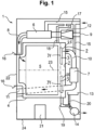
- the washer-dryer 1 shown in Fig. 1 according to a first embodiment of a washer-dryer 1 according to the invention has a tub (also referred to as a "lye container") 4 and a laundry drum 5 rotatably mounted therein about an axis 23.
- the lye container 4 is connected via a lye drain line 19 to a lye pump 14, which can dispose of an aqueous liquid from the lye container 4 to an outside of the washer-dryer 1.
- the direction of flow of water or an aqueous liquid, and of process air, respectively, is shown by arrows in Fig. 1 .
- the laundry drum 5 is loaded with laundry items to be treated through an access door, i.e.
- the washer-dryer 1 is connected to an external water supply of the washer-dryer 1, which is not shown here, via a water supply system 15.
- the water supply system 15 is connected to a rinsing tray 17, from which portions of detergent or washing aid can be conveyed into the lye container 4 via a supply line 18 with the aid of water from the water supply system 15.
- the washer-dryer shown in Fig. 1 also has a heat pump, of which a condenser 6, an evaporator 7 and a compressor 21 are shown in Fig. 1 .
- the compressor 21 is arranged on a base plate 24.
- the refrigeration circuit of the heat pump connecting these parts and a throttle not shown here is not shown for reasons of clarity.
- the condenser 6 and the evaporator 7 are located on opposite sides of the laundry drum 5, in particular substantially on opposite sides of a surface parallel to a bottom plate 24 through an axis of rotation 23 through the laundry drum 5. Moreover, the condenser 6 is arranged above the laundry drum 5, while the evaporator 7 is arranged below the axis of rotation 23.
- the condenser 6 and evaporator 7 are connected to the water supply system 15 so that they can be cleaned by means of water from the water supply system 15, in particular of lint which may get there during a laundry drying process.
- the washer-dryer 1 of Fig. 1 which operates according to the exhaust air principle, that air is drawn as process air from a storage room of washer-dryer 1 by means of a blower 12 from a supply air inlet 9 into the supply air duct 8.
- the blower 12 is located directly behind the supply air inlet 9.
- the condenser 6, in which the process air can be heated, is arranged in the supply air duct 8. The heated process air then passes from the supply air duct 8 via a sleeve 16 into the laundry drum 5.
- the then damp-warm process air exits the laundry drum 5 or the lye container 4 through a rear part and passes into an exhaust air duct 10, in which the evaporator 7 is located.
- the moist warm process air is cooled below the dew point, whereby the moisture contained therein condenses and passes via a condensate collector 13, here designed as a condensate tray, into a condensate drain line 20 and finally to the lye pump 14, with the aid of which the condensate can be pumped off for disposal and conveyed to the outside of the washer-dryer 1.
- the cooled process air is finally conveyed to an exhaust outlet 11 of the washer-dryer 1, where it can enter the installation room.
- the process air can be circulated repeatedly through the process air circuit.
- a fluff filter 3 which is here shaped as a circular ring and thus - considering its threedimensional nature - as a kind of donut - is placed inside the tub 4, i.e. between the tub 4 and the drum 5.
- the fluff filter 3 is placed in front of the rear wall 2 of the tub 4.
- Figure 2 shows a vertically cut section of the rear part of a washer-dryer according to a second embodiment of the invention in which the fluff filter 3 is placed in the drum 4 on a rear wall 2 of the tub 4 in a manner such that there is a gap 25 between the fluff filter 3 and the rear tub wall 2. Details of the fixation of the fluff filter 3 are not shown in order not to complicate Figure 2 .
- the fluff filter 3 forms here a circular ring that is coaxial with the rotation axis 23 of the drum 5.
- 26 means a central opening in the tub 5 for the (rotation) shaft and bearings.
- 34 indicates the surface of the fluff filter 3 directly opposite to the drum 5.
- Process air is led from the drum 5 through the tub 4 including the fluff filter 3 through an outlet hole 27 in the rear tub wall 2 to an exhaust air duct 10.
- Figure 3 shows an enlarged perspective view of a vertically cut section of the rear half of a washer-dryer according to a further embodiment of the invention.
- 30 indicates the rear half part of the tub 4, 29 the drum support and 31 a bearings section.
- 28 refers to the rear part of drum backsheet and 3 to the fluff filter.
- the gap 25 between fluff filter 3 and rear tub wall is indicated by 25.
- Figure 4 shows a top view on the tub 4 and drum 5 of a washer-dryer according to a further embodiment of the present invention. It can be seen from this top view that the fluff filter 3 extends over the drum 5 the border of which can be easily seen from the top. Moreover, it can be seen that the fluff filter 3 forms a circular ring that is coaxial with the rotation axis 23 of the drum 5. The outlet hole 27 provides the access to an exhaust air duct in the rear tub wall.
- Figure 5 shows a top view on the rear part of a tub of a washer-dryer according to a further embodiment of the present invention.
- 32 refers to solid sections which allow to fix the fluff filter 3 that forms here also a circular ring in a certain distance (gap) to the rear wall of the tub 4 which cannot be seen here in detail.
- 33 refers to a filter mesh or solid non-filter section facing the outlet hole of the tub 4. It contains here the outlet hole 27 in the rear tub wall.
- Figure 6 shows an exploded view of the rear part of a drum and a rear half part 30 of the tub of a washer-dryer according to a still further embodiment of the present invention.
- 28 indicates the rear part of drum backsheet, 23 the rotation axis, and 29 the drum support.
- the fluff filter 3 is the same circular ring shaped fluff filter 3 shown in Figure 5 .
Landscapes
- Engineering & Computer Science (AREA)
- Textile Engineering (AREA)
- Detail Structures Of Washing Machines And Dryers (AREA)
Abstract
Description
- The invention relates to a washer-dryer, including a tub in which a drum for receiving laundry items is rotatably provided; a process air circuit for passing an air flow of process air through the drum comprising a blower for driving the air flow; an air heating device for heating the process air before the process air enters the drum; and a fluff filter. The invention also relates to a process for operating the washer-dryer.
- Current solutions for fluff filtering in for example heat pump washer-dryers use a filter mesh in a particular section of the process air circuit. Depending on the type of automation of the filtering, such a filter can be manually cleaned by the user or by means of self-cleaning systems. Most of the self-cleaning systems involve the spraying of water.
- In for example heat pump washer-dryers, the outlet for process air from the tub is located often in the rear part of the tub. The process air is then guided to the evaporator of the heat pump through an air duct. In this concept, the filter is integrated in the air duct and additionally a cleaning system which is generally based on flushing water is involved.
- The
publication EP 3 825 450 A1 discloses a laundry treating appliance with a filter. Disclosed is in particular a combination washer/dryer comprising: a tub at least partially defining a tub interior with a tub access opening; a rotatable drum located within the tub interior and at least partially defining a treating chamber with a treating chamber access opening; a drying airduct having an inlet formed in the tub and defining a cross-sectional area at the inlet; and a filter having a front face overlying the inlet and having a surface area greater than the cross-sectional area. In the embodiment shown in Fig. 3A a cross-sectional side-view of the filter of the combination washing and drying machine is shown. The filter can be positioned between the drum and the tub at the inlet of the drying air duct. It can include a seat portion which can extend into at least a portion of the drying air duct past the inlet. - In view of this situation it was an object of the present invention to provide a washer-dryer which allows an improved filtering of the process air after it has been used for drying laundry items. In particular, the use of the fluff filter should be improved. Preferably, the cleaning of the fluff filter should be improved such that for example fluff can be dealt with in a better way and time intervals between cleaning steps of the fluff filter can become shorter. A further object was the provision of a process for operating this dryer.
- This object is achieved according to the present invention by the washer-dryer and the processes for its operation pursuant to the independent claims. Preferred embodiments of the washer-dryer according to the invention are shown especially in the dependent claims. Preferred embodiments of the processes correspond to preferred embodiments of the washer-dryer and vice versa even if not expressly stated herein.
- The invention is thus directed to a washer-dryer including a tub in which a drum for receiving laundry items is rotatably provided; a process air circuit for passing an air flow of process air through the drum comprising a blower for driving the air flow; an air heating device for heating the process air before the process air enters the drum; and a fluff filter; wherein the fluff filter is provided inside the tub between the tub and the drum.
- In a preferred embodiment of the washer-dryer of the present invention, the air heating device is selected from the group consisting of an electric resistance heater and a condenser of a heat pump, or a combination thereof. Preferably, the air heating device is the condenser of a heat pump.
- A heat pump circuit used in a preferred embodiment of the present invention includes a refrigerant channel for circulating a refrigerant, the condenser as a heat source, the evaporator as a heat sink, an expansion device for expanding the refrigerant flow, and a compressor for driving and compressing the refrigerant, the refrigerant circulating sequentially through the compressor, the condenser, the expansion device and the evaporator.
- In the heat pump circuit the refrigerant is circulated and thereby cyclically compressed and expanded as well as cooled and heated, on purpose of absorbing heat in the evaporator by evaporating the refrigerant at low pressure, and releasing heat in the condenser by condensing the refrigerant at high pressure.
- In accordance with a preferred embodiment of the invention the washer-dryer comprises a control device for controlling operation of the washer-dryer. In the embodiment in which a heat pump is used, the expansion device is usually a variable valve operably connected to the control device. Such operation may be of a switching type, whereby the valve is switched between an open position for recirculating a part of the refrigerant and a closed position which cuts off any recirculation. Alternatively such operation may allow varying the amount of refrigerant which is recirculated, either stepwise or continuously.
- In a particular preferred embodiment of the washer-dryer, the fluff filter is provided on or close to an inner wall of the tub. Preferably, the inner wall is a rear wall of the tub.
- The shape of the fluff filter is not especially limited. In any way, it is preferred that the fluff filter is coaxial with the rotation axis of the drum.
- In a particularly preferred embodiment, the fluff filter has essentially the form of a circular ring that is placed on the rear tub wall or separated by a small gap from the rear tub wall. Such a shape of the fluff filter can be considered to be a donut-shape in the interior side of tub, in particular at the rear part thereof.
- One particular implementation could be one where there is a fluff filter section covering around 300° of the circumference. This section of filter could be dimensioned as desired according to the needs. The outlet hole (for process air which is to enter the exhaust air duct) is preferably designed to be protected against washing/spinning water to reach the hole and subsequently the exhaust air duct.
- It is therefore preferred in the washer-dryer of the present invention that a hole is provided in the rear wall of the tub to an exhaust air duct of the process air circuit. I.e. the hole serves as an access from the process air to the air duct.
- In the washer-dryer of the present invention, the surface of the fluff filter directly opposite to the drum is preferably in the range of from 100 to 700 cm2, more preferably in the range of from 200 to 600 cm2.
- The fluff filter can be fixed to the tub by means of welding or gluing. It is also noted that the air flow might be further improved in that the tub can be slightly modified if more section is required for the fluff filter, i.e. the filter tunnel, for the air flow.
- The invention is moreover directed to a process for the operation of a washer-dryer including a tub in which a drum for receiving laundry items is rotatably provided; a process air circuit for passing an air flow of process air through the drum comprising a blower for driving the air flow; an air heating device for heating the process air before the process air enters the drum; and a fluff filter that is provided inside the tub between the tub and the drum; comprising the following steps in a washing process:
- (a) introducing laundry items in the drum;
- (b) introducing water and detergent in the tub in an amount sufficient to produce a lye solution in the tub and the drum;
- (c) heating the lye solution by means of the air heating device;
- (d) washing the laundry items and cleaning the fluff filter by means of the lye solution;
- (e) pumping off the used lye solution;
- (f) rinsing the laundry items and the fluff filter by means of an aqueous solution; and
- (g) pumping off the used aqueous solution.
- Finally, the invention is directed to a process for the operation of a washer-dryer including a tub in which a drum for receiving laundry items is rotatably provided; a process air circuit for passing an air flow of process air through the drum comprising a blower for driving the air flow; an air heating device for heating the process air before the process air enters the drum; and a fluff filter that is provided inside the tub between the tub and the drum; comprising the following steps in a drying process:
- (a) introducing laundry items in the drum;
- (b) rotating the drum;
- (c) heating process air by means of the air heating device;
- (d) driving the process air through the process air circuit by means of the blower including driving the process air through the fluff filter in the tub through an outlet hole into an outlet duct; and
- (e) repeating steps (a) to (d) until a preset time has passed or a preset humidity level in the laundry items is reached.
- Advantages of the invention include an improvement of the performance of the washer-dryer by allowing a prolonged use of the fluff filter without the necessity of cleaning it since it is possible to have a fluff filter with a large surface area. Moreover, if the cleaning of the fluff filter is eventually necessary, the filter cleaning can occur during a washing process. If drying cycles are always preceded by washing cycles, it is possible to avoid a dedicated cleaning system, for example a water spraying system with nozzles, hosing, electro-valve. This reduces complexity, cost and mechanical failures. However, since the usage of the washer-dryer could be wash only, dry only or wash&dry, it is recommended to include a dedicated cleaning system in the washer-dryer to ensure a clean filter in any scenario or to set up a procedure to ensure filter cleaning between consecutive process programs that involve only the drying of laundry items. Additionally, programs such as "tub and drum cleaning" can be used to clean in depth the filtering system including the fluff filter from time to time apart from the normal way of cleaning the filter in every cycle. This is not possible with other filtering solutions inside air ducts.
- Since the fluff filter is not located inside process air ducts but in the interior side of the tub, preferably in the rear part of the tub, the filter area can be significantly increased compared to the state of the art. For instance, with the present invention filter areas of more than 600 cm2, for example even more than 700 cm2, could be implemented. This means that blockage of the fluff filter due to fluff is more difficult to occur which has a big impact on pressure drop, fan behaviour and therefore drying performance. Bigger areas of the fluff filter allow getting the fluff filter dirty due to fluff with no need of cleaning before or after every drying process in the washer-dryer.
- In the present invention, the filter section including the fluff filter can be dimensioned as desired. There is no need to use the full circumference if the fluff filter has for example in essence the shape of a circle ring.
- The present invention allows it moreover that a connection between filter duct and hole-to-air-duct is protected or designed in order to prevent or avoid any liquid water from a washing phase to reaching the air duct.
- Another advantage of the washer-dryer pursuant to the present invention is that fluff and hair is gathered inside the tub so that it can be directly pumped out with a drain pump of the washer-dryer which is in general its main pump that can easily handle dirty water.
- In embodiments of the inventive washer-dryer, the air circulation will be from an inlet bellow, through drum and tub and then through the fluff filter to the evaporator. Since in a preferred embodiment, the donut shape of the fluff filter is aligned with the drum, the air distribution inside the drum will be improved and a bypass effect reduced.
- Further details, benefits and advantages of the invention will appear from the subsequent description of specific embodiments with references to
Figures 1 to 6 , wherein - Figure 1
- shows a schematic view of a washer-dryer according to a first embodiment of the invention, which includes a heat pump circuit and further a fluff filter inside the tub;
- Figure 2
- shows a vertically cut section of the rear part of a washer-dryer according to a second embodiment of the invention in which the fluff filter is placed in the drum in a manner such that there is a gap between the fluff filter and the rear tub wall;
- Figure 3
- shows an enlarged perspective view of a vertically cut section of the rear part of a washer-dryer according to a further embodiment of the invention;
- Figure 4
- shows a top view on the tub and drum of a washer-dryer according to a further embodiment of the present invention;
- Figure 5
- shows a top view on the rear part of a tub of a washer-dryer according to a further embodiment of the present invention; and
- Figure 6
- shows an exploded view of the rear part of a drum and a tub of a washer-dryer according to a still further embodiment of the present invention.
- The washer-
dryer 1 shown inFig. 1 according to a first embodiment of a washer-dryer 1 according to the invention has a tub (also referred to as a "lye container") 4 and alaundry drum 5 rotatably mounted therein about anaxis 23. Thelye container 4 is connected via alye drain line 19 to alye pump 14, which can dispose of an aqueous liquid from thelye container 4 to an outside of the washer-dryer 1. The direction of flow of water or an aqueous liquid, and of process air, respectively, is shown by arrows inFig. 1 . Thelaundry drum 5 is loaded with laundry items to be treated through an access door, i.e. a filling opening, 22 at the front side of washer-dryer 1. In order to be able to wash laundry in the washer-dryer 1, the washer-dryer 1 is connected to an external water supply of the washer-dryer 1, which is not shown here, via awater supply system 15. Thewater supply system 15 is connected to a rinsingtray 17, from which portions of detergent or washing aid can be conveyed into thelye container 4 via asupply line 18 with the aid of water from thewater supply system 15. - The washer-dryer shown in
Fig. 1 also has a heat pump, of which acondenser 6, anevaporator 7 and acompressor 21 are shown inFig. 1 . Thecompressor 21 is arranged on abase plate 24. InFig. 1 , the refrigeration circuit of the heat pump connecting these parts and a throttle not shown here is not shown for reasons of clarity. - In the first embodiment of a washer-
dryer 1 according to the invention shown inFig. 1 , thecondenser 6 and theevaporator 7 are located on opposite sides of thelaundry drum 5, in particular substantially on opposite sides of a surface parallel to abottom plate 24 through an axis ofrotation 23 through thelaundry drum 5. Moreover, thecondenser 6 is arranged above thelaundry drum 5, while theevaporator 7 is arranged below the axis ofrotation 23. - The
condenser 6 andevaporator 7 are connected to thewater supply system 15 so that they can be cleaned by means of water from thewater supply system 15, in particular of lint which may get there during a laundry drying process. - For drying damp laundry in the
laundry drum 5, it is provided in the washer-dryer 1 ofFig. 1 , which operates according to the exhaust air principle, that air is drawn as process air from a storage room of washer-dryer 1 by means of ablower 12 from asupply air inlet 9 into thesupply air duct 8. In this case, theblower 12 is located directly behind thesupply air inlet 9. Thecondenser 6, in which the process air can be heated, is arranged in thesupply air duct 8. The heated process air then passes from thesupply air duct 8 via asleeve 16 into thelaundry drum 5. After passing through thelaundry drum 5 and drying the damp laundry located therein - not shown here - the then damp-warm process air exits thelaundry drum 5 or thelye container 4 through a rear part and passes into anexhaust air duct 10, in which theevaporator 7 is located. In theevaporator 7, the moist warm process air is cooled below the dew point, whereby the moisture contained therein condenses and passes via acondensate collector 13, here designed as a condensate tray, into acondensate drain line 20 and finally to thelye pump 14, with the aid of which the condensate can be pumped off for disposal and conveyed to the outside of the washer-dryer 1. The cooled process air is finally conveyed to anexhaust outlet 11 of the washer-dryer 1, where it can enter the installation room. This is however a non-limiting example. In preferred embodiments, the process air can be circulated repeatedly through the process air circuit. - In the washer-dryer 1 a
fluff filter 3 which is here shaped as a circular ring and thus - considering its threedimensional nature - as a kind of donut - is placed inside thetub 4, i.e. between thetub 4 and thedrum 5. Thefluff filter 3 is placed in front of therear wall 2 of thetub 4. However, there is agap 25 betweenfluff filter 3 and therear wall 2 to allow the air from thedrum 5 to flow around and reach thefluff filter 3 over an increased area into theexhaust air duct 10. It is not shown in detail inFig. 1 in which manner thefluff filter 3 is fixed to therear wall 2 of thetub 4, but this can be easily contemplated. -
Figure 2 shows a vertically cut section of the rear part of a washer-dryer according to a second embodiment of the invention in which thefluff filter 3 is placed in thedrum 4 on arear wall 2 of thetub 4 in a manner such that there is agap 25 between thefluff filter 3 and therear tub wall 2. Details of the fixation of thefluff filter 3 are not shown in order not to complicateFigure 2 . - The
fluff filter 3 forms here a circular ring that is coaxial with therotation axis 23 of thedrum 5. 26 means a central opening in thetub 5 for the (rotation) shaft and bearings. 34 indicates the surface of thefluff filter 3 directly opposite to thedrum 5. Process air is led from thedrum 5 through thetub 4 including thefluff filter 3 through anoutlet hole 27 in therear tub wall 2 to anexhaust air duct 10. -
Figure 3 shows an enlarged perspective view of a vertically cut section of the rear half of a washer-dryer according to a further embodiment of the invention. 30 indicates the rear half part of thetub gap 25 betweenfluff filter 3 and rear tub wall is indicated by 25. -
Figure 4 shows a top view on thetub 4 anddrum 5 of a washer-dryer according to a further embodiment of the present invention. It can be seen from this top view that thefluff filter 3 extends over thedrum 5 the border of which can be easily seen from the top. Moreover, it can be seen that thefluff filter 3 forms a circular ring that is coaxial with therotation axis 23 of thedrum 5. Theoutlet hole 27 provides the access to an exhaust air duct in the rear tub wall. -
Figure 5 shows a top view on the rear part of a tub of a washer-dryer according to a further embodiment of the present invention. 32 refers to solid sections which allow to fix thefluff filter 3 that forms here also a circular ring in a certain distance (gap) to the rear wall of thetub 4 which cannot be seen here in detail. 33 refers to a filter mesh or solid non-filter section facing the outlet hole of thetub 4. It contains here theoutlet hole 27 in the rear tub wall. -
Figure 6 shows an exploded view of the rear part of a drum and arear half part 30 of the tub of a washer-dryer according to a still further embodiment of the present invention. 28 indicates the rear part of drum backsheet, 23 the rotation axis, and 29 the drum support. Thefluff filter 3 is the same circular ring shapedfluff filter 3 shown inFigure 5 . -
- 1
- Washer dryer
- 2
- Rear wall of tub; rear tub wall
- 3
- Fluff filter
- 4
- Tub; lye container
- 5
- Drum; laundry drum
- 6
- Condenser
- 7
- Evaporator
- 8
- Supply air duct
- 9
- Supply air inlet
- 10
- Exhaust air duct
- 11
- Exhaust air outlet
- 12
- Blower
- 13
- Condensate collector
- 14
- Pump, lye pump
- 15
- Water supply system
- 16
- Collar; sleeve
- 17
- Rinsing tray; Washing-in bowl; detergent chamber
- 18
- Supply line, connection between rinsing tray induction bowl and tub
- 19
- Lye drain line
- 20
- Condensate drain line
- 21
- Compressor
- 22
- Access door (for introducing laundry items to be treated)
- 23
- Rotation axis
- 24
- Base plate
- 25
- Gap (between fluff filter and rear tub wall)
- 26
- Central opening for shaft and bearings
- 27
- Outlet hole in rear tub wall
- 28
- Rear part of drum backsheet
- 29
- Drum support
- 30
- Rear half part of tub
- 31
- Bearings section
- 32
- Solid sections
- 33
- Filter mesh or solid non-filter section facing the outlet hole of the tub
- 34
- Surface of the fluff filter directly opposite to the drum
Claims (10)
- A washer-dryer (1), including a tub (4) in which a drum (5) for receiving laundry items is rotatably provided; a process air circuit (8,9,10,11) for passing an air flow of process air through the drum (5) comprising a blower (12) for driving the air flow; an air heating device (6) for heating the process air before the process air enters the drum (5); and a fluff filter (3); characterized in that the fluff filter (3) is provided inside the tub (4) between the tub (4) and the drum (5).
- Washer-dryer (1) according to claim 1, wherein the air heating device (6) is selected from the group consisting of an electric resistance heater and a condenser (6) of a heat pump (6,7,21), or a combination thereof.
- Washer-dryer (1) according to claim 1 or 2, wherein the fluff filter (3) is provided on or close to an inner wall (2) of the tub (4).
- Washer-dryer (1) according to claim 3, wherein the inner wall (2) is a rear wall (2) of the tub (4).
- Washer-dryer (1) according to any of claims 1 to 4, wherein the fluff filter (3) is coaxial with the rotation axis (23) of the drum (5).
- Washer-dryer (1) according to any of claims 1 to 5, wherein the fluff filter (3) has essentially the form of a circular ring that is placed on the rear wall (2) of the tub (4) or separated by a small gap from the rear tub wall (2).
- Washer-dryer (1) according to any of claims 1 to 6, wherein a hole (27) is provided in the rear wall (2) of the tub (4) to an exhaust air duct (10) of the process air circuit.
- Washer-dryer (1) according to any of claims 1 to 7, wherein the surface of the fluff filter (3) directly opposite to the drum (5) is in the range of from 100 to 700 cm2.
- Process for the operation of a washer-dryer (1), including a tub (4) in which a drum (5) for receiving laundry items is rotatably provided; a process air circuit (8,9,10,11) for passing an air flow of process air through the drum (5) comprising a blower (12) for driving the air flow; an air heating device (6) for heating the process air before the process air enters the drum (5); and a fluff filter (3) that is provided inside the tub (4) between the tub (4) and the drum (5); comprising the following steps in a washing process:(a) introducing laundry items in the drum (5);(b) introducing water and detergent in the tub (4) in an amount sufficient to produce a lye solution in the tub (4) and the drum (5);(c) heating the lye solution by means of the air heating device (6);(d) washing the laundry items and cleaning the fluff filter (3) by means of the lye solution;(e) pumping off the used lye solution;(f) rinsing the laundry items and the fluff filter (3) by means of an aqueous solution; and(g) pumping off the used aqueous solution.
- Process for the operation of a washer-dryer (1) including a tub (4) in which a drum (5) for receiving laundry items is rotatably provided; a process air circuit (8,9,10,11) for passing an air flow of process air through the drum (5) comprising a blower (12) for driving the air flow; a air heating device (6) for heating the process air before the process air enters the drum (5); and a fluff filter (3) that is provided inside the tub (4) between the tub (4) and the drum (5); comprising the following steps in a drying process:(a) introducing laundry items in the drum (5);(b) heating process air by means of the air heating device (6);(c) driving the process air through the process air circuit by means of the blower (12) including driving the process air through the fluff filter (3) in the tub (4) through an outlet hole (27); and(d) repeating steps (a) to (c) until a preset time has lapsed or a preset humidity level in the laundry items is reached.
Applications Claiming Priority (1)
| Application Number | Priority Date | Filing Date | Title |
|---|---|---|---|
| EP22382025 | 2022-01-18 |
Publications (2)
| Publication Number | Publication Date |
|---|---|
| EP4212662A1 true EP4212662A1 (en) | 2023-07-19 |
| EP4212662B1 EP4212662B1 (en) | 2026-04-08 |
Family
ID=80222632
Family Applications (1)
| Application Number | Title | Priority Date | Filing Date |
|---|---|---|---|
| EP22213393.6A Active EP4212662B1 (en) | 2022-01-18 | 2022-12-14 | Washer-dryer comprising a fluff filter in the tub and process for operating the washer-dryer |
Country Status (2)
| Country | Link |
|---|---|
| EP (1) | EP4212662B1 (en) |
| CN (1) | CN116463832A (en) |
Citations (8)
| Publication number | Priority date | Publication date | Assignee | Title |
|---|---|---|---|---|
| GB981437A (en) * | 1961-05-11 | 1965-01-27 | Borg Warner | Lint filtering and disposal arrangement for clothes drying machine |
| JPH0779903B2 (en) * | 1988-10-24 | 1995-08-30 | 株式会社東芝 | Washing and drying machine |
| US20100175432A1 (en) * | 2006-08-10 | 2010-07-15 | Masanori Komori | Washing and drying apparatus and method of controlling the same |
| US20140150279A1 (en) * | 2009-05-28 | 2014-06-05 | Ig Geun KWON | Laundry machine having a drying function |
| WO2015101892A1 (en) * | 2013-12-31 | 2015-07-09 | Indesit Company S.P.A. | Washing/drying machine with cleaning device for a drying air filter |
| WO2016108795A1 (en) * | 2014-12-30 | 2016-07-07 | Arçelik Anonim Şirketi | A laundry washing and drying machine |
| WO2021012765A1 (en) * | 2019-07-24 | 2021-01-28 | 海信(山东)冰箱有限公司 | Washing machine |
| EP3825450A1 (en) | 2019-11-21 | 2021-05-26 | Whirlpool Corporation | Laundry treating appliance with a filter |
Family Cites Families (2)
| Publication number | Priority date | Publication date | Assignee | Title |
|---|---|---|---|---|
| US4848105A (en) * | 1988-07-25 | 1989-07-18 | White Consolidated Industries, Inc. | Self-cleaning lint filter for clothes washing machine |
| DE102015105046B4 (en) * | 2015-04-01 | 2018-02-22 | Miele & Cie. Kg | Tumble dryer with lint pocket |
-
2022
- 2022-12-14 EP EP22213393.6A patent/EP4212662B1/en active Active
-
2023
- 2023-01-13 CN CN202310067553.8A patent/CN116463832A/en active Pending
Patent Citations (8)
| Publication number | Priority date | Publication date | Assignee | Title |
|---|---|---|---|---|
| GB981437A (en) * | 1961-05-11 | 1965-01-27 | Borg Warner | Lint filtering and disposal arrangement for clothes drying machine |
| JPH0779903B2 (en) * | 1988-10-24 | 1995-08-30 | 株式会社東芝 | Washing and drying machine |
| US20100175432A1 (en) * | 2006-08-10 | 2010-07-15 | Masanori Komori | Washing and drying apparatus and method of controlling the same |
| US20140150279A1 (en) * | 2009-05-28 | 2014-06-05 | Ig Geun KWON | Laundry machine having a drying function |
| WO2015101892A1 (en) * | 2013-12-31 | 2015-07-09 | Indesit Company S.P.A. | Washing/drying machine with cleaning device for a drying air filter |
| WO2016108795A1 (en) * | 2014-12-30 | 2016-07-07 | Arçelik Anonim Şirketi | A laundry washing and drying machine |
| WO2021012765A1 (en) * | 2019-07-24 | 2021-01-28 | 海信(山东)冰箱有限公司 | Washing machine |
| EP3825450A1 (en) | 2019-11-21 | 2021-05-26 | Whirlpool Corporation | Laundry treating appliance with a filter |
Also Published As
| Publication number | Publication date |
|---|---|
| EP4212662B1 (en) | 2026-04-08 |
| CN116463832A (en) | 2023-07-21 |
Similar Documents
| Publication | Publication Date | Title |
|---|---|---|
| EP2623663B1 (en) | Laundry machine with drying duct comprising a nozzle | |
| US9903067B2 (en) | Laundry machine | |
| EP2107157B1 (en) | Laundry treating machine and controlling method of the same | |
| JP6626795B2 (en) | Washing and drying machine | |
| EP2107148A1 (en) | Laundry treating machine | |
| AU2010205103A1 (en) | Laundry treating apparatus | |
| EP2990524B1 (en) | Heat pump laundry dryer | |
| EP2634301B1 (en) | Household laundry washing and drying machine with a condensing device and method of operating this machine | |
| KR102483851B1 (en) | Apparatus for laundry treatment and method of controlling the same | |
| JP6910771B2 (en) | Clothes dryer | |
| JP2017176562A (en) | Washing and drying machine | |
| JPH01212599A (en) | Washer-dryer | |
| US20240401262A1 (en) | Washing machine having drying function | |
| GB2172977A (en) | Washing machine with tumble dryer | |
| EP2990520B1 (en) | Laundry dryer including a heat pump system | |
| EP4212662A1 (en) | Washer-dryer comprising a fluff filter in the tub and process for operating the washer-dryer | |
| JP6400339B2 (en) | Clothes dryer | |
| JP2017012871A (en) | Washing and drying machine | |
| KR101314625B1 (en) | Clothes Treating Apparatus | |
| KR100741798B1 (en) | Dryer integrated washing machine | |
| JP7544939B2 (en) | Drum type washing machine | |
| KR20150024552A (en) | Laundry Machine and Control method for Laundry Machine | |
| WO2005054563A1 (en) | A washer/dryer with a condenser and a lint collection propeller | |
| JP2017185191A (en) | Washing and drying machine | |
| KR20110079389A (en) | Laundry treatment furniture |
Legal Events
| Date | Code | Title | Description |
|---|---|---|---|
| PUAI | Public reference made under article 153(3) epc to a published international application that has entered the european phase |
Free format text: ORIGINAL CODE: 0009012 |
|
| STAA | Information on the status of an ep patent application or granted ep patent |
Free format text: STATUS: THE APPLICATION HAS BEEN PUBLISHED |
|
| AK | Designated contracting states |
Kind code of ref document: A1 Designated state(s): AL AT BE BG CH CY CZ DE DK EE ES FI FR GB GR HR HU IE IS IT LI LT LU LV MC ME MK MT NL NO PL PT RO RS SE SI SK SM TR |
|
| STAA | Information on the status of an ep patent application or granted ep patent |
Free format text: STATUS: REQUEST FOR EXAMINATION WAS MADE |
|
| 17P | Request for examination filed |
Effective date: 20240119 |
|
| RBV | Designated contracting states (corrected) |
Designated state(s): AL AT BE BG CH CY CZ DE DK EE ES FI FR GB GR HR HU IE IS IT LI LT LU LV MC ME MK MT NL NO PL PT RO RS SE SI SK SM TR |
|
| STAA | Information on the status of an ep patent application or granted ep patent |
Free format text: STATUS: EXAMINATION IS IN PROGRESS |
|
| 17Q | First examination report despatched |
Effective date: 20250410 |
|
| GRAP | Despatch of communication of intention to grant a patent |
Free format text: ORIGINAL CODE: EPIDOSNIGR1 |
|
| STAA | Information on the status of an ep patent application or granted ep patent |
Free format text: STATUS: GRANT OF PATENT IS INTENDED |
|
| INTG | Intention to grant announced |
Effective date: 20251209 |
|
| GRAS | Grant fee paid |
Free format text: ORIGINAL CODE: EPIDOSNIGR3 |
|
| GRAA | (expected) grant |
Free format text: ORIGINAL CODE: 0009210 |
|
| STAA | Information on the status of an ep patent application or granted ep patent |
Free format text: STATUS: THE PATENT HAS BEEN GRANTED |
|
| AK | Designated contracting states |
Kind code of ref document: B1 Designated state(s): AL AT BE BG CH CY CZ DE DK EE ES FI FR GB GR HR HU IE IS IT LI LT LU LV MC ME MK MT NL NO PL PT RO RS SE SI SK SM TR |
|
| REG | Reference to a national code |
Ref country code: CH Ref legal event code: F10 Free format text: ST27 STATUS EVENT CODE: U-0-0-F10-F00 (AS PROVIDED BY THE NATIONAL OFFICE) Effective date: 20260408 Ref country code: GB Ref legal event code: FG4D |
|
| REG | Reference to a national code |
Ref country code: DE Ref legal event code: R096 Ref document number: 602022033949 Country of ref document: DE |