EP4212465A1 - Sheet conveying device and image forming system provided with same - Google Patents
Sheet conveying device and image forming system provided with same Download PDFInfo
- Publication number
- EP4212465A1 EP4212465A1 EP21879950.0A EP21879950A EP4212465A1 EP 4212465 A1 EP4212465 A1 EP 4212465A1 EP 21879950 A EP21879950 A EP 21879950A EP 4212465 A1 EP4212465 A1 EP 4212465A1
- Authority
- EP
- European Patent Office
- Prior art keywords
- conveyance
- sheet
- guide
- conveyance unit
- unit
- Prior art date
- Legal status (The legal status is an assumption and is not a legal conclusion. Google has not performed a legal analysis and makes no representation as to the accuracy of the status listed.)
- Granted
Links
Images




Classifications
-
- B—PERFORMING OPERATIONS; TRANSPORTING
- B65—CONVEYING; PACKING; STORING; HANDLING THIN OR FILAMENTARY MATERIAL
- B65H—HANDLING THIN OR FILAMENTARY MATERIAL, e.g. SHEETS, WEBS, CABLES
- B65H5/00—Feeding articles separated from piles; Feeding articles to machines
- B65H5/06—Feeding articles separated from piles; Feeding articles to machines by rollers or balls, e.g. between rollers
- B65H5/062—Feeding articles separated from piles; Feeding articles to machines by rollers or balls, e.g. between rollers between rollers or balls
-
- B—PERFORMING OPERATIONS; TRANSPORTING
- B65—CONVEYING; PACKING; STORING; HANDLING THIN OR FILAMENTARY MATERIAL
- B65H—HANDLING THIN OR FILAMENTARY MATERIAL, e.g. SHEETS, WEBS, CABLES
- B65H29/00—Delivering or advancing articles from machines; Advancing articles to or into piles
- B65H29/12—Delivering or advancing articles from machines; Advancing articles to or into piles by means of the nip between two, or between two sets of, moving tapes or bands or rollers
- B65H29/125—Delivering or advancing articles from machines; Advancing articles to or into piles by means of the nip between two, or between two sets of, moving tapes or bands or rollers between two sets of rollers
-
- B—PERFORMING OPERATIONS; TRANSPORTING
- B65—CONVEYING; PACKING; STORING; HANDLING THIN OR FILAMENTARY MATERIAL
- B65H—HANDLING THIN OR FILAMENTARY MATERIAL, e.g. SHEETS, WEBS, CABLES
- B65H29/00—Delivering or advancing articles from machines; Advancing articles to or into piles
- B65H29/58—Article switches or diverters
- B65H29/60—Article switches or diverters diverting the stream into alternative paths
-
- B—PERFORMING OPERATIONS; TRANSPORTING
- B65—CONVEYING; PACKING; STORING; HANDLING THIN OR FILAMENTARY MATERIAL
- B65H—HANDLING THIN OR FILAMENTARY MATERIAL, e.g. SHEETS, WEBS, CABLES
- B65H31/00—Pile receivers
- B65H31/24—Pile receivers multiple or compartmented, e.d. for alternate, programmed, or selective filling
-
- B—PERFORMING OPERATIONS; TRANSPORTING
- B65—CONVEYING; PACKING; STORING; HANDLING THIN OR FILAMENTARY MATERIAL
- B65H—HANDLING THIN OR FILAMENTARY MATERIAL, e.g. SHEETS, WEBS, CABLES
- B65H5/00—Feeding articles separated from piles; Feeding articles to machines
- B65H5/36—Article guides or smoothers, e.g. movable in operation
-
- B—PERFORMING OPERATIONS; TRANSPORTING
- B65—CONVEYING; PACKING; STORING; HANDLING THIN OR FILAMENTARY MATERIAL
- B65H—HANDLING THIN OR FILAMENTARY MATERIAL, e.g. SHEETS, WEBS, CABLES
- B65H2301/00—Handling processes for sheets or webs
- B65H2301/40—Type of handling process
- B65H2301/44—Moving, forwarding, guiding material
- B65H2301/445—Moving, forwarding, guiding material stream of articles separated from each other
- B65H2301/4455—Diverting a main stream into part streams
-
- B—PERFORMING OPERATIONS; TRANSPORTING
- B65—CONVEYING; PACKING; STORING; HANDLING THIN OR FILAMENTARY MATERIAL
- B65H—HANDLING THIN OR FILAMENTARY MATERIAL, e.g. SHEETS, WEBS, CABLES
- B65H2402/00—Constructional details of the handling apparatus
- B65H2402/10—Modular constructions, e.g. using preformed elements or profiles
-
- B—PERFORMING OPERATIONS; TRANSPORTING
- B65—CONVEYING; PACKING; STORING; HANDLING THIN OR FILAMENTARY MATERIAL
- B65H—HANDLING THIN OR FILAMENTARY MATERIAL, e.g. SHEETS, WEBS, CABLES
- B65H2402/00—Constructional details of the handling apparatus
- B65H2402/30—Supports; Subassemblies; Mountings thereof
- B65H2402/31—Pivoting support means
-
- B—PERFORMING OPERATIONS; TRANSPORTING
- B65—CONVEYING; PACKING; STORING; HANDLING THIN OR FILAMENTARY MATERIAL
- B65H—HANDLING THIN OR FILAMENTARY MATERIAL, e.g. SHEETS, WEBS, CABLES
- B65H2402/00—Constructional details of the handling apparatus
- B65H2402/40—Details of frames, housings or mountings of the whole handling apparatus
- B65H2402/44—Housings
- B65H2402/441—Housings movable for facilitating access to area inside the housing, e.g. pivoting or sliding
-
- B—PERFORMING OPERATIONS; TRANSPORTING
- B65—CONVEYING; PACKING; STORING; HANDLING THIN OR FILAMENTARY MATERIAL
- B65H—HANDLING THIN OR FILAMENTARY MATERIAL, e.g. SHEETS, WEBS, CABLES
- B65H2402/00—Constructional details of the handling apparatus
- B65H2402/40—Details of frames, housings or mountings of the whole handling apparatus
- B65H2402/45—Doors
-
- B—PERFORMING OPERATIONS; TRANSPORTING
- B65—CONVEYING; PACKING; STORING; HANDLING THIN OR FILAMENTARY MATERIAL
- B65H—HANDLING THIN OR FILAMENTARY MATERIAL, e.g. SHEETS, WEBS, CABLES
- B65H2404/00—Parts for transporting or guiding the handled material
- B65H2404/60—Other elements in face contact with handled material
- B65H2404/61—Longitudinally-extending strips, tubes, plates, or wires
- B65H2404/611—Longitudinally-extending strips, tubes, plates, or wires arranged to form a channel
-
- B—PERFORMING OPERATIONS; TRANSPORTING
- B65—CONVEYING; PACKING; STORING; HANDLING THIN OR FILAMENTARY MATERIAL
- B65H—HANDLING THIN OR FILAMENTARY MATERIAL, e.g. SHEETS, WEBS, CABLES
- B65H2601/00—Problem to be solved or advantage achieved
- B65H2601/10—Ensuring correct operation
- B65H2601/11—Clearing faulty handling, e.g. jams
-
- B—PERFORMING OPERATIONS; TRANSPORTING
- B65—CONVEYING; PACKING; STORING; HANDLING THIN OR FILAMENTARY MATERIAL
- B65H—HANDLING THIN OR FILAMENTARY MATERIAL, e.g. SHEETS, WEBS, CABLES
- B65H2601/00—Problem to be solved or advantage achieved
- B65H2601/30—Facilitating or easing
- B65H2601/32—Facilitating or easing entities relating to handling machine
- B65H2601/321—Access
-
- B—PERFORMING OPERATIONS; TRANSPORTING
- B65—CONVEYING; PACKING; STORING; HANDLING THIN OR FILAMENTARY MATERIAL
- B65H—HANDLING THIN OR FILAMENTARY MATERIAL, e.g. SHEETS, WEBS, CABLES
- B65H2801/00—Application field
- B65H2801/03—Image reproduction devices
- B65H2801/06—Office-type machines, e.g. photocopiers
-
- B—PERFORMING OPERATIONS; TRANSPORTING
- B65—CONVEYING; PACKING; STORING; HANDLING THIN OR FILAMENTARY MATERIAL
- B65H—HANDLING THIN OR FILAMENTARY MATERIAL, e.g. SHEETS, WEBS, CABLES
- B65H2801/00—Application field
- B65H2801/24—Post -processing devices
- B65H2801/27—Devices located downstream of office-type machines
Definitions
- the present invention relates to a sheet conveyance apparatus which conveys a sheet and an image forming system including the sheet conveyance apparatus.
- a sheet post-processing apparatus which can perform a binding processing in which a plurality of sheets on which an image is formed by an image forming apparatus such as a copying machine or a printer are stacked and then the stack of sheets is stapled with staples, a punching processing in which holes are formed in the stack of sheets by a punching apparatus, and the like.
- the above-described sheet post-processing apparatus is utilized when performing the post-processing such as the binding processing for a relatively large number of sheets.
- Patent Document 1 discloses a relay conveyance device including at least two inversion paths which pass at least two inversion units, a first branching part branching to at least one of the two inversion paths, and a first merging part merging at least the two inversion paths.
- the first branching part and the first merging part are controlled so as to alternately switch the inversion paths and to convey the sheet, and the inter-sheet time of the sheet passing through the first merging part is measured and then the conveyance of sheet in at least the two inversion paths is controlled such that the inter-sheet times becomes uniform.
- the conveyance paths on which the sheet stop position and the processing apparatus are provided are provided, and the distances between the branching part and the merging part on the conveyance paths are set to equal, so that the constant inter-sheet time can be maintained before branching and after merging without requiring complicated control.
- Patent Document 2 discloses a relay conveyance apparatus including an opening/closing cover for treating the sheet jamming whose one end side is supported by a supporting member, a first hinge part which supports the opening/closing cover so as to be turnable upward and downward at the upper end side of the supporting member, and a second hinge part which supports the supporting member to a base member so as to be turnable upward and downward at the lower end side of the supporting member.
- Patent Document 1 Japanese Patent Laid-Open 2019-167226
- Patent Document 2 Japanese Patent Laid-Open 2000-153934
- the opening/closing cover is displaced upward in a state in which the posture of the opening/closing cover after opening is maintained substantially parallel to the posture before opening.
- the conveyance units are disposed in the upper-and-lower direction, since there is no space for displacing the opening/closing cover upward, the same drawing-out operation of the conveyance unit as in the prior art is required.
- a sheet conveyance apparatus including two or more conveyance paths disposed in parallel in the upper-and-lower direction and capable of easily removing a sheet stopped in the lower conveyance path, and an image forming system including the same.
- a sheet conveyance apparatus of the present invention includes: a first conveyance unit which includes a first upper conveyance guide facing an upper surface of a sheet, a first lower conveyance guide facing a lower surface of the sheet and a conveyance member conveying the sheet along the first upper conveyance guide and the first lower conveyance guide, and forms a first sheet conveyance path; a second conveyance unit which is disposed below the first conveyance unit in parallel, includes a second upper conveyance guide facing the upper surface of the sheet, a second lower conveyance guide facing the lower surface of the sheet and a conveyance member conveying the sheet along the second upper conveyance guide and the second lower conveyance guide, and forms a second sheet conveyance path; and an apparatus main body in which the first conveyance unit and the second conveyance unit are housed, wherein the second conveyance unit can be drawn out horizontally to a front side of the apparatus main body along a front-and-rear direction perpendicular to a sheet conveyance direction with respect to the apparatus main body, the second upper
- the movable guide part of the upper conveyance guide of the lower conveyance unit is turned upward around the hinge portion, so that interference with the upper conveyance unit can be avoided, and the upper conveyance guide can be smoothly opened and closed over a wide range during the sheet jamming treatment work.
- the drawing amount of the lower conveyance unit can be reduced as compared with the conventional one, and it is not necessary to leave a large space for drawing out the lower conveyance unit in front of the sheet conveyance apparatus.
- the workability of the sheet jamming treatment is improved.
- FIG. 1 is a view schematically showing an inner structure of an image forming system 200 provided with a relay conveyance apparatus 26 as an example of a sheet conveyance apparatus of the present invention.
- the image forming system 200 including an image forming apparatus 100, the relay conveyance apparatus 26, and a sheet post-processing apparatus 30 will be described.
- the image forming apparatus 100 is an inkjet recording type printer, and includes a sheet feeding part 4 disposed in the lower portion of the image forming apparatus 100, a sheet conveyance part 5 which feeds the sheet S stored in the sheet feeding part 4 to an image forming part 6, and the image forming part 6 disposed above the sheet feeding part 4.
- the image forming part 6 includes a print head 6a and a conveyance part 6b disposed so as to face the print head 6a.
- the conveying part 6a includes an endless conveyance belt wound around a plurality of rollers including a drive roller.
- the sheet S conveyed by the sheet conveyance part 5 passes under the print head 6a in a state of being attracted and held by the conveyance belt 7a by a sheet suction part provided in the inside space of the conveyance belt 7a.
- the sheet S on which the predetermined image is recorded by the image forming part 6 is discharged from a discharge rollers pair 50 and carried into the relay conveyance apparatus 26.
- the relay conveyance apparatus 26 is disposed independently between the image forming apparatus 100 and the sheet post-processing apparatus 30, and relays the sheet S discharged from the image forming apparatus 100 to the sheet post-processing apparatus 30.
- the relay conveyance apparatus 26 performs an inversion processing in which the sheet S on which the image is recorded by the image forming apparatus 100 is turned upside down and a drying processing in which the ink on the sheet S is dried.
- the sheet S carried in from the relay carry-in port 51 of the relay conveyance apparatus 26 passes through a first conveyance path 52a and is conveyed to a first inversion conveyance path 53a.
- the first inversion conveyance path 53a turns the sheet S upside down by switching (switching back) the conveyance direction of the sheet S conveyed from the first conveyance path 52a.
- a second conveyance path 52b branched from the first conveyance path 52a is provided, and the sheet S passed through the second conveyance path 52b is conveyed to a second inversion conveyance path 53b.
- the second inversion conveyance path 53b turns the sheet S upside down by switching (switching back) the conveyance direction of the sheet S conveyed from the second conveyance path 52b.
- the sheet S which is turned upside down by the first inversion conveyance path 53a or the second inversion conveyance path 53b is conveyed to a third conveyance path 52c.
- the sheet S is conveyed to a first bypass conveyance path 54c and a second bypass conveyance path 54b branched from a third conveyance path 52c at the branching part DB.
- the first bypass conveyance path 54a and the second bypass conveyance path 54b are provided with a first correction unit 55 and a second correction unit 56, respectively.
- the first correction unit 55 and the second correction unit 56 correct the position of the sheet S in the width direction of the sheet S (the direction perpendicular to the paper plane of FIG. 1 ).
- a distance from the branching part DB to the merging part DJ is equal. Further, a distance from the branching part DB to the sheet stop position (the horizontal portion in FIG. 1 ) is equal to a conveyance interval of the sheets S (an interval between the sheets). Therefore, for example, by stopping the first sheet S turned upside down in the first inversion conveyance path 53a in the second bypass conveyance path 54b and stopping the second sheet S turned upside down in the second inversion conveyance path 53b in the first bypass conveyance path 54a, the stopped sheet S can be conveyed again while maintaining the interval between the sheets.
- the turning operation of the second sheet S can be started in the other of the first inversion conveyance path 53a and the second inversion conveyance path 53b.
- the waiting time for the turning and the position correcting of the sheet S can be shortened, and the processing efficiency (a number of sheets processed per unit time) of the sheet S by the relay conveyance apparatus 26 can be enhanced.
- the sheet S passed through the first bypass conveyance path 54a and the second bypass conveyance path 54b is conveyed to a fourth conveyance path 52d at the merging part DJ.
- the sheet S passes through the fourth conveyance path 52d, and is carried into the sheet post-processing apparatus 30 through a relay carry-out port 57.
- an in-body discharge conveyance path 58 branched from the fourth conveyance path 52d is provided, and the sheet S passed through the in-body discharge conveyance path 58 is discharged to a collection tray 61 by an in-body discharge rollers pair 60.
- the conveyance path is switched by a third branch guide 62 provided at a branching part of the fourth conveyance path 52d and the in-body discharge conveyance path 58, and the next sheet S existing in the relay conveyance apparatus 26 is discharged to the collection tray 61 via the in-body discharge conveyance path 58 and the in-body discharge rollers pair 60.
- a conveyance rollers pair 59 (conveyance members) for conveying the sheet S is disposed in place on the first conveyance path 52a to the fourth conveyance path 52d, the first bypass conveyance path 54a, the second bypass conveyance path 54b, and the in-body discharge conveyance path 58.
- a punching apparatus 31 which punches the carried-in sheet S
- a stapler 33 which stacks a plurality of the carried-in sheets S, aligns the ends of the stack of the sheets S, and binds them with staples
- a binding/folding unit 36 which staples the center of the stack of sheets S and then folds it around the stapled portion to form a booklet.
- a main tray 34a which can be lifted and lowered to a position suitable for discharging the sheet S
- a sub-tray 34b fixed to the upper portion of the sheet post-processing apparatus 30 and a booklet tray 34c on which a bundle of the sheets S folded into a booklet shape by the binding/folding unit 36 is discharged.
- FIG. 2 is a perspective view showing a first conveyance unit 70a and a second conveyance unit 70b constituting the first bypass conveyance path 54a and the second bypass conveyance path 54b.
- the first conveyance unit 70a (an upper conveyance unit) and the second conveyance unit 70b (the lower conveyance unit) are disposed in parallel so as to be overlapped in the upper-and-lower direction.
- FIG. 2 shows a state in which the second conveyance unit 70b is drawn out from below the first conveyance unit 70a in the sheet width direction (the white arrow direction in FIG. 2 ) perpendicular to the conveyance direction.
- the first conveyance unit 70a is disposed above the second conveyance unit 70b and below the collection tray 61, and includes a first upper conveyance guide 71 and a first lower conveyance guide 73 which face the upper and lower surfaces of the sheet S.
- the first upper conveyance guide 71 and the first lower conveyance guide 73 forms the conveyance surfaces (the conveyance guide) of the first bypass conveyance path 54a (see FIG. 1 ).
- the upper rollers constituting the conveyance rollers pairs 59 in the first bypass conveyance path 54a are supported by the first upper conveyance guide 71.
- the lower roller constituting the conveyance rollers pairs 59 are supported by the first lower conveyance guide 73.
- the second conveyance unit 70b is disposed below the first conveyance unit 70a, and includes a second upper conveyance guide 75 and a second lower conveyance guide 77 which face the upper and lower surfaces of the sheet S.
- the second upper conveyance guide 75 and the second lower conveyance guide 77 form the conveyance surface (the conveyance guide) of the second bypass conveyance path 54b (see FIG. 1 ).
- the upper roller constituting the conveyance rollers pairs 59 in the second bypass conveyance path 54a are supported by the second upper conveyance guide 75.
- the lower roller constituting the conveying rollers pairs 59 are supported by the second lower conveyance guide 77.
- the second upper conveyance guide 75 is supported so as to be opened and closed in the upper-and-lower direction with respect to the second lower conveyance guide 77, with one end side in the width direction perpendicular to the conveyance direction of the sheet S (the rear side of the relay conveyance apparatus 26, and the rear side of FIG. 2 ) as a turning support shaft 75a and the front side of the relay conveyance apparatus 26 (the front side in FIG. 2 ) opposite to the turning support shaft 75a as the turning side.
- the second conveyance unit 70b is drawn out from below the first conveyance unit 70a to the front side of the relay conveyance apparatus 26.
- FIG. 3 is a perspective view showing a state in which the second upper conveyance guide 75 is opened.
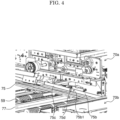
- FIG. 4 is a partially enlarged view showing the hinge part 75d of the second upper conveyance guide 75 in FIG. 3 and its periphery.
- the first conveyance unit 70a is disposed above the second upper conveyance guide 75, and interferes with the first conveyance unit 70a when the second upper conveyance guide 75 is turned upward. Therefore, in order to open the conveyance surfaces of the second bypass conveyance path 54b in a wide range by increasing the turning angle of the second upper conveyance guide 75, it is necessary to increase the drawing amount of the second conveyance unit 70b with respect to the first conveyance unit 70a.
- the second upper conveyance guide 75 includes a guide main body part 75b and a movable guide part 75c.
- the guide main body part 75b has a front turning end 75b1 (the front end portion in FIG. 3 ) that can be turned upward and downward with the rear end edge on the rear side of the relay conveyance apparatus 26 as a turning support shaft 75a (see FIG. 2 ).
- the movable guide part 75b is supported by the turning end 75b1 of the guide main body part 75a via a hinge part 75d.
- FIG. 5 is a perspective view showing a state in which the movable guide part 75c is turned relative to the main guide body part 75b from the state shown in FIG. 3 .
- FIG. 6 is a partially enlarged view of the hinge part 75d of the second upper conveyance guide 75 in FIG. 5 and its periphery. As shown in FIG. 5 and FIG. 6 , the movable guide part 75c of the second upper conveyance guide 75 is turned upward around the hinge part 75d to avoid interference with the first conveyance unit 70a, and the second upper conveyance guide 75 can be opened and closed smoothly and in a wide range during the sheet jamming treatment.
- the drawing amount of the second conveyance unit 70b can be reduced to about 1/2 to 1/3 of the conventional amount, and it is not necessary to leave a large space for drawing the second conveyance unit 70b in front of the relay conveyance apparatus 26. Further, since the movement of the user at the time of the drawing operation of the second conveyance unit 70a is also suppressed, the workability of the sheet jamming treatment is improved.
- the hinge part 75d is positioned on the rear side (the inside) of the front side end (the left front side in FIG. 4 ) of the first conveyance unit 70a in a state where the second conveyance unit 70b is drawn out, it becomes difficult to turn the movable guide part 75c.
- the hinge part 75d is located on the front side (the outside) of the front end edge of the first conveyance unit 70a in a state where the second conveyance unit 70b is drawn out.
- FIG. 7 is a perspective view showing the collection tray 61 provided inside the relay conveyance apparatus 26.
- the collection tray 61 has a tray body part 63 and a tray movable part 65.
- the tray body part 63 is fixed to the rear frame 80a of the relay conveyance apparatus 26.
- the tray movable part 65 is supported by the front side (the front side in FIG. 7 ) of the tray body part 63 via a hinge part 67 in a turnable manner.
- FIG. 8 and FIG. 9 are perspective views showing the collection tray 61 and the first conveyance unit 70a in a state in which the tray movable part 65 is disposed in a sheet receiving position and a retreat position, respectively.
- the first upper conveyance guide 71 is supported so as to be opened and closed in the upper-and-lower direction with respect to the first lower conveyance guide 73, with one end side in the width direction perpendicular to the conveyance direction of the sheet S (the back side of the relay conveyance apparatus 26, the right side of FIG. 8 ) as a turning support shaft 71a and the front side of the relay conveyance apparatus 26 (the left side in FIG. 8 ) opposite to the turning support shaft 71a as a turning end.
- the tray movable part 65 is disposed in the sheet receiving position.
- the tray movable part 65 disposed in the sheet receiving position is on the same plane as the tray body part 63, and forms a sheet stacking surface on which the sheet S discharged from the in-body discharge rollers pair 60 is stacked, together with the tray body part 63.
- the collection tray movable part 65 is movable to a retreat position turned upward from the sheet receiving position.
- FIG. 10 is a perspective view showing a state in which the first upper conveyance guide 71 is opened.
- the turning end of the first upper conveyance guide 71 is turned upward to open the conveyance surfaces from the front side of the relay conveyance apparatus 26 (the left side in FIG. 10 ), and the upper and lower conveyance rollers constituting the conveyance rollers pairs 59 are separated away each other.
- the jammed paper S can be pulled out to the front side of the relay conveyance apparatus 26 (the left side in FIG. 10 ) and removed.
- the tray movable part 65 is positioned just above the first upper conveyance guide 71. Therefore, when the first upper conveyance guide 71 is turned upward, the tray movable part 65 is pushed up by the first upper conveyance guide 71 and shifted from the sheet receiving position to the retreat position.
- the collection tray 61 is disposed just above the first bypass conveyance path 54a, interference between the collection tray 61 and the first upper conveyance guide 71 when the first upper conveyance guide 71 is opened can be avoided, and the first upper conveyance guide 71 can be smoothly opened and closed during the sheet jamming treatment work. Accordingly, the space for disposing the collection tray 61 can be saved, and the degree of freedom of layout in the relay conveyance apparatus 26 can be increased.
- the present invention is not limited to the above embodiments, and various modifications are possible without departing from the spirit of the present invention.
- the present invention can be similarly applied when the image forming apparatus 100 and the sheet post-processing apparatus 30 are provided with two conveyance paths arranged in parallel in the upper-and-lower direction.
- the relay conveyance apparatus 26 including the first conveyance unit 70a and the second conveyance unit 70b disposed in parallel in the upper-and-lower direction is described, but the present invention can also be applied to the case where the relay conveyance device has three or more conveyance units disposed in parallel in the upper-and-lower direction.
- the upper conveyance guide of the conveyance unit other than the uppermost conveyance unit may be provided with a guide body part and a movable guide part which are connected to each other via a hinge part.
- the present invention is applicable to a sheet conveyance apparatus for conveying a sheet.
- a sheet conveying device which can easily remove a sheet stopped in a lower conveying path in a configuration having two or more conveyance paths disposed in parallel in the upper-and-lower direction.
Landscapes
- Engineering & Computer Science (AREA)
- Mechanical Engineering (AREA)
- Delivering By Means Of Belts And Rollers (AREA)
- Feeding Of Articles By Means Other Than Belts Or Rollers (AREA)
- Paper Feeding For Electrophotography (AREA)
Abstract
Description
- The present invention relates to a sheet conveyance apparatus which conveys a sheet and an image forming system including the sheet conveyance apparatus.
- Conventionally, a sheet post-processing apparatus is known, which can perform a binding processing in which a plurality of sheets on which an image is formed by an image forming apparatus such as a copying machine or a printer are stacked and then the stack of sheets is stapled with staples, a punching processing in which holes are formed in the stack of sheets by a punching apparatus, and the like. The above-described sheet post-processing apparatus is utilized when performing the post-processing such as the binding processing for a relatively large number of sheets.
- As a method for connecting the image forming apparatus and the sheet post-processing apparatus, there is proposed a method for disposing a relay conveyance apparatus between the image forming apparatus and the sheet post-processing apparatus. For example, Patent Document 1 discloses a relay conveyance device including at least two inversion paths which pass at least two inversion units, a first branching part branching to at least one of the two inversion paths, and a first merging part merging at least the two inversion paths. The first branching part and the first merging part are controlled so as to alternately switch the inversion paths and to convey the sheet, and the inter-sheet time of the sheet passing through the first merging part is measured and then the conveyance of sheet in at least the two inversion paths is controlled such that the inter-sheet times becomes uniform.
- As in the relay conveyance apparatus described in Patent Document 1, the conveyance paths on which the sheet stop position and the processing apparatus are provided are provided, and the distances between the branching part and the merging part on the conveyance paths are set to equal, so that the constant inter-sheet time can be maintained before branching and after merging without requiring complicated control.
- By the way, in a configuration including a plurality of conveyance units disposed in the upper-and-lower direction as disclosed in Patent Document 1, it is necessary to draw out the conveyance unit forward from the relay conveyance apparatus when the sheet jamming occurred in the lower conveyance unit is treated. At this time, in order to smoothly carry out the treatment of the sheet jamming, it is necessary to draw out the unit at least over the width of the conveyance path (the sheet width), then to open and close the conveyance guide, and then remove the sheet. Therefore, there is a problem that it is necessary to leave a large space in front of the relay conveyance apparatus, and that when there is no space, the user has to move to a position where he does not interfere with the drawing of the conveyance unit.
-
Patent Document 2 discloses a relay conveyance apparatus including an opening/closing cover for treating the sheet jamming whose one end side is supported by a supporting member, a first hinge part which supports the opening/closing cover so as to be turnable upward and downward at the upper end side of the supporting member, and a second hinge part which supports the supporting member to a base member so as to be turnable upward and downward at the lower end side of the supporting member. By the two-state hinge function of the supporting member, the posture of the opening/closing cover after opening is substantially parallel to that before opening, and a jam treatment space having a uniform height is formed below the lower surface of the opening/closing cover. - [Patent Document 1]
Japanese Patent Laid-Open 2019-167226 Japanese Patent Laid-Open 2000-153934 - In the configuration disclosed in
Patent Document 2, the opening/closing cover is displaced upward in a state in which the posture of the opening/closing cover after opening is maintained substantially parallel to the posture before opening. In the configuration in which the conveyance units are disposed in the upper-and-lower direction, since there is no space for displacing the opening/closing cover upward, the same drawing-out operation of the conveyance unit as in the prior art is required. - In view of the above problems, it is an object of the present invention to provide a sheet conveyance apparatus including two or more conveyance paths disposed in parallel in the upper-and-lower direction and capable of easily removing a sheet stopped in the lower conveyance path, and an image forming system including the same.
- In order to achieve the above purpose, a sheet conveyance apparatus of the present invention includes: a first conveyance unit which includes a first upper conveyance guide facing an upper surface of a sheet, a first lower conveyance guide facing a lower surface of the sheet and a conveyance member conveying the sheet along the first upper conveyance guide and the first lower conveyance guide, and forms a first sheet conveyance path; a second conveyance unit which is disposed below the first conveyance unit in parallel, includes a second upper conveyance guide facing the upper surface of the sheet, a second lower conveyance guide facing the lower surface of the sheet and a conveyance member conveying the sheet along the second upper conveyance guide and the second lower conveyance guide, and forms a second sheet conveyance path; and an apparatus main body in which the first conveyance unit and the second conveyance unit are housed, wherein the second conveyance unit can be drawn out horizontally to a front side of the apparatus main body along a front-and-rear direction perpendicular to a sheet conveyance direction with respect to the apparatus main body, the second upper conveyance guide of the second conveyance unit includes: a guide main body part turnable upward and downward with respect to the apparatus main body with a rear end edge as a turning support shaft and a front end edge as a turning end; and a movable guide part coupled to the turning end of the guide main body part via a hinge part in a turnable manner.
- According to the first configuration of the present invention, the movable guide part of the upper conveyance guide of the lower conveyance unit is turned upward around the hinge portion, so that interference with the upper conveyance unit can be avoided, and the upper conveyance guide can be smoothly opened and closed over a wide range during the sheet jamming treatment work. Further, the drawing amount of the lower conveyance unit can be reduced as compared with the conventional one, and it is not necessary to leave a large space for drawing out the lower conveyance unit in front of the sheet conveyance apparatus. Further, since the movement of the user at the time of the draw-out operation of the lower conveyance unit is suppressed, the workability of the sheet jamming treatment is improved.
-
- [
FIG.1] FIG. 1 is a view schematically showing an inner structure of an image forming system 200 including arelay conveyance apparatus 26 that is an example of a sheet conveyance apparatus according to the present invention. - [
FIG. 2] FIG. 2 is a perspective view showing afirst conveyance unit 70a and asecond conveyance unit 70b constituting a firstbypass conveyance path 54a and a secondbypass conveyance path 54b of therelay conveyance apparatus 26. - [
FIG. 3] FIG. 3 is a perspective view showing a state in which a secondupper conveyance guide 75 is opened from the state shown inFIG. 2 . - [
FIG. 4] FIG. 4 is a partial enlarged view showing ahinge part 75d of the secondupper conveyance guide 75 inFIG. 3 and its peripheral. - [
FIG. 5] FIG. 5 is a perspective view showing a state in which amovable guide part 75c is turned relative to a guidemain body part 75b from the state shown inFIG. 3 . - [
FIG. 6] FIG. 6 is a partial enlarged view showing thehinge part 75d of the secondupper conveyance guide 75 inFIG. 5 and its periphery. - [
FIG. 7] FIG. 7 is a perspective view showing acollection tray 61 provided inside therelay conveyance apparatus 26. - [
FIG. 8] FIG. 8 is a perspective view showing thecollection tray 61 and thefirst conveyance unit 70a in a state in which a collection traymovable part 65 is disposed in a sheet receiving position. - [
FIG. 9] FIG. 9 is a perspective view showing thecollection tray 61 and thefirst conveyance unit 70a in a state in which the collection traymovable part 65 is disposed in a retreat position. - [
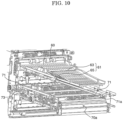
FIG. 10] FIG. 10 is a perspective view showing thecollection tray 61 and thefirst conveyance unit 70a in a state in which anupper conveyance guide 71 is opened. - Hereinafter, with reference to the drawings, one embodiment of the present invention will be described.
FIG. 1 is a view schematically showing an inner structure of an image forming system 200 provided with arelay conveyance apparatus 26 as an example of a sheet conveyance apparatus of the present invention. With reference toFIG. 1 , the image forming system 200 including animage forming apparatus 100, therelay conveyance apparatus 26, and asheet post-processing apparatus 30 will be described. - The
image forming apparatus 100 is an inkjet recording type printer, and includes asheet feeding part 4 disposed in the lower portion of theimage forming apparatus 100, asheet conveyance part 5 which feeds the sheet S stored in thesheet feeding part 4 to animage forming part 6, and theimage forming part 6 disposed above thesheet feeding part 4. - The
image forming part 6 includes aprint head 6a and aconveyance part 6b disposed so as to face theprint head 6a. The conveyingpart 6a includes an endless conveyance belt wound around a plurality of rollers including a drive roller. The sheet S conveyed by thesheet conveyance part 5 passes under theprint head 6a in a state of being attracted and held by the conveyance belt 7a by a sheet suction part provided in the inside space of the conveyance belt 7a. The sheet S on which the predetermined image is recorded by theimage forming part 6 is discharged from adischarge rollers pair 50 and carried into therelay conveyance apparatus 26. - The
relay conveyance apparatus 26 is disposed independently between theimage forming apparatus 100 and thesheet post-processing apparatus 30, and relays the sheet S discharged from theimage forming apparatus 100 to thesheet post-processing apparatus 30. Therelay conveyance apparatus 26 performs an inversion processing in which the sheet S on which the image is recorded by theimage forming apparatus 100 is turned upside down and a drying processing in which the ink on the sheet S is dried. As shown inFIG. 1 , the sheet S carried in from the relay carry-inport 51 of therelay conveyance apparatus 26 passes through afirst conveyance path 52a and is conveyed to a firstinversion conveyance path 53a. The firstinversion conveyance path 53a turns the sheet S upside down by switching (switching back) the conveyance direction of the sheet S conveyed from thefirst conveyance path 52a. - A second conveyance path 52b branched from the
first conveyance path 52a is provided, and the sheet S passed through the second conveyance path 52b is conveyed to a secondinversion conveyance path 53b. The secondinversion conveyance path 53b turns the sheet S upside down by switching (switching back) the conveyance direction of the sheet S conveyed from the second conveyance path 52b. - The sheet S which is turned upside down by the first
inversion conveyance path 53a or the secondinversion conveyance path 53b is conveyed to athird conveyance path 52c. The sheet S is conveyed to a first bypass conveyance path 54c and a secondbypass conveyance path 54b branched from athird conveyance path 52c at the branching part DB. The firstbypass conveyance path 54a and the secondbypass conveyance path 54b are provided with afirst correction unit 55 and asecond correction unit 56, respectively. Thefirst correction unit 55 and thesecond correction unit 56 correct the position of the sheet S in the width direction of the sheet S (the direction perpendicular to the paper plane ofFIG. 1 ). - In the first
bypass conveyance path 54a and the secondbypass conveyance path 54b, a distance from the branching part DB to the merging part DJ is equal. Further, a distance from the branching part DB to the sheet stop position (the horizontal portion inFIG. 1 ) is equal to a conveyance interval of the sheets S (an interval between the sheets). Therefore, for example, by stopping the first sheet S turned upside down in the firstinversion conveyance path 53a in the secondbypass conveyance path 54b and stopping the second sheet S turned upside down in the secondinversion conveyance path 53b in the firstbypass conveyance path 54a, the stopped sheet S can be conveyed again while maintaining the interval between the sheets. That is, before one of the firstinversion conveyance path 53a and the secondinversion conveyance path 53b completes the turning operation of the first sheet S, the turning operation of the second sheet S can be started in the other of the firstinversion conveyance path 53a and the secondinversion conveyance path 53b. - In the same manner, by alternately carrying the sheet S into the
first correction unit 55 and thesecond correction unit 56 disposed on the firstbypass conveyance path 54a and the secondbypass conveyance path 54b, respectively, before one of thefirst correction unit 55 and thesecond correction unit 56 completes the position correcting operation of the first sheet S, the position correcting operation of the second sheet S can be started in the other of thefirst correction unit 55 and thesecond correction unit 56. - As a result, the waiting time for the turning and the position correcting of the sheet S can be shortened, and the processing efficiency (a number of sheets processed per unit time) of the sheet S by the
relay conveyance apparatus 26 can be enhanced. - The sheet S passed through the first
bypass conveyance path 54a and the secondbypass conveyance path 54b is conveyed to afourth conveyance path 52d at the merging part DJ. The sheet S passes through thefourth conveyance path 52d, and is carried into thesheet post-processing apparatus 30 through a relay carry-outport 57. - In addition, an in-body
discharge conveyance path 58 branched from thefourth conveyance path 52d is provided, and the sheet S passed through the in-bodydischarge conveyance path 58 is discharged to acollection tray 61 by an in-bodydischarge rollers pair 60. When a sheet jamming occurs in the sheetpost-processing apparatus 30, the conveyance path is switched by athird branch guide 62 provided at a branching part of thefourth conveyance path 52d and the in-bodydischarge conveyance path 58, and the next sheet S existing in therelay conveyance apparatus 26 is discharged to thecollection tray 61 via the in-bodydischarge conveyance path 58 and the in-body discharge rollers pair 60. - A conveyance rollers pair 59 (conveyance members) for conveying the sheet S is disposed in place on the
first conveyance path 52a to thefourth conveyance path 52d, the firstbypass conveyance path 54a, the secondbypass conveyance path 54b, and the in-bodydischarge conveyance path 58. - Inside the sheet
post-processing apparatus 30, there are provided apunching apparatus 31 which punches the carried-in sheet S, astapler 33 which stacks a plurality of the carried-in sheets S, aligns the ends of the stack of the sheets S, and binds them with staples, and a binding/folding unit 36 which staples the center of the stack of sheets S and then folds it around the stapled portion to form a booklet. On the side surface of the sheetpost-processing apparatus 30, there are provided amain tray 34a which can be lifted and lowered to a position suitable for discharging the sheet S, a sub-tray 34b fixed to the upper portion of the sheetpost-processing apparatus 30, and abooklet tray 34c on which a bundle of the sheets S folded into a booklet shape by the binding/folding unit 36 is discharged. -
FIG. 2 is a perspective view showing afirst conveyance unit 70a and asecond conveyance unit 70b constituting the firstbypass conveyance path 54a and the secondbypass conveyance path 54b. Thefirst conveyance unit 70a (an upper conveyance unit) and thesecond conveyance unit 70b (the lower conveyance unit) are disposed in parallel so as to be overlapped in the upper-and-lower direction.FIG. 2 shows a state in which thesecond conveyance unit 70b is drawn out from below thefirst conveyance unit 70a in the sheet width direction (the white arrow direction inFIG. 2 ) perpendicular to the conveyance direction. - The
first conveyance unit 70a is disposed above thesecond conveyance unit 70b and below thecollection tray 61, and includes a firstupper conveyance guide 71 and a firstlower conveyance guide 73 which face the upper and lower surfaces of the sheet S. The firstupper conveyance guide 71 and the firstlower conveyance guide 73 forms the conveyance surfaces (the conveyance guide) of the firstbypass conveyance path 54a (seeFIG. 1 ). The upper rollers constituting the conveyance rollers pairs 59 in the firstbypass conveyance path 54a are supported by the firstupper conveyance guide 71. The lower roller constituting the conveyance rollers pairs 59 are supported by the firstlower conveyance guide 73. - The
second conveyance unit 70b is disposed below thefirst conveyance unit 70a, and includes a secondupper conveyance guide 75 and a secondlower conveyance guide 77 which face the upper and lower surfaces of the sheet S. The secondupper conveyance guide 75 and the secondlower conveyance guide 77 form the conveyance surface (the conveyance guide) of the secondbypass conveyance path 54b (seeFIG. 1 ). The upper roller constituting the conveyance rollers pairs 59 in the secondbypass conveyance path 54a are supported by the secondupper conveyance guide 75. The lower roller constituting the conveying rollers pairs 59 are supported by the secondlower conveyance guide 77. - The second
upper conveyance guide 75 is supported so as to be opened and closed in the upper-and-lower direction with respect to the secondlower conveyance guide 77, with one end side in the width direction perpendicular to the conveyance direction of the sheet S (the rear side of therelay conveyance apparatus 26, and the rear side ofFIG. 2 ) as a turningsupport shaft 75a and the front side of the relay conveyance apparatus 26 (the front side inFIG. 2 ) opposite to the turningsupport shaft 75a as the turning side. - When the sheet S carried into the
second conveyance unit 70b (the secondbypass conveyance path 54b) is jammed, as shown inFIG. 2 , thesecond conveyance unit 70b is drawn out from below thefirst conveyance unit 70a to the front side of therelay conveyance apparatus 26. -
FIG. 3 is a perspective view showing a state in which the secondupper conveyance guide 75 is opened.FIG. 4 is a partially enlarged view showing thehinge part 75d of the secondupper conveyance guide 75 inFIG. 3 and its periphery. From the state shown inFIG. 2 , when the turning end of the secondupper conveyance guide 75 is turned upward to open the conveyance surfaces from the front side of the relay conveyance apparatus 26 (the left front side inFIG. 3 ) and the upper and lower conveyance rollers constituting theconveyance roller pair 59 separates away each other, the sheet S jammed in thesecond conveyance unit 70b can be pulled out to the front side of therelay conveyance apparatus 26 and removed - Here, the
first conveyance unit 70a is disposed above the secondupper conveyance guide 75, and interferes with thefirst conveyance unit 70a when the secondupper conveyance guide 75 is turned upward. Therefore, in order to open the conveyance surfaces of the secondbypass conveyance path 54b in a wide range by increasing the turning angle of the secondupper conveyance guide 75, it is necessary to increase the drawing amount of thesecond conveyance unit 70b with respect to thefirst conveyance unit 70a. - Therefore, in the present embodiment, the second
upper conveyance guide 75 includes a guidemain body part 75b and amovable guide part 75c. The guidemain body part 75b has a front turning end 75b1 (the front end portion inFIG. 3 ) that can be turned upward and downward with the rear end edge on the rear side of therelay conveyance apparatus 26 as a turningsupport shaft 75a (seeFIG. 2 ). Themovable guide part 75b is supported by the turning end 75b1 of the guidemain body part 75a via ahinge part 75d. -
FIG. 5 is a perspective view showing a state in which themovable guide part 75c is turned relative to the mainguide body part 75b from the state shown inFIG. 3 .FIG. 6 is a partially enlarged view of thehinge part 75d of the secondupper conveyance guide 75 inFIG. 5 and its periphery. As shown inFIG. 5 andFIG. 6 , themovable guide part 75c of the secondupper conveyance guide 75 is turned upward around thehinge part 75d to avoid interference with thefirst conveyance unit 70a, and the secondupper conveyance guide 75 can be opened and closed smoothly and in a wide range during the sheet jamming treatment. - In addition, the drawing amount of the
second conveyance unit 70b can be reduced to about 1/2 to 1/3 of the conventional amount, and it is not necessary to leave a large space for drawing thesecond conveyance unit 70b in front of therelay conveyance apparatus 26. Further, since the movement of the user at the time of the drawing operation of thesecond conveyance unit 70a is also suppressed, the workability of the sheet jamming treatment is improved. - If the
hinge part 75d is positioned on the rear side (the inside) of the front side end (the left front side inFIG. 4 ) of thefirst conveyance unit 70a in a state where thesecond conveyance unit 70b is drawn out, it becomes difficult to turn themovable guide part 75c. In order to smoothly avoid interference with thefirst conveyance unit 70a owing to the turning of themovable guide part 75c, it is preferable that thehinge part 75d is located on the front side (the outside) of the front end edge of thefirst conveyance unit 70a in a state where thesecond conveyance unit 70b is drawn out. -
FIG. 7 is a perspective view showing thecollection tray 61 provided inside therelay conveyance apparatus 26. Thecollection tray 61 has atray body part 63 and a traymovable part 65. Thetray body part 63 is fixed to therear frame 80a of therelay conveyance apparatus 26. The traymovable part 65 is supported by the front side (the front side inFIG. 7 ) of thetray body part 63 via ahinge part 67 in a turnable manner. -
FIG. 8 andFIG. 9 are perspective views showing thecollection tray 61 and thefirst conveyance unit 70a in a state in which the traymovable part 65 is disposed in a sheet receiving position and a retreat position, respectively. - The first
upper conveyance guide 71 is supported so as to be opened and closed in the upper-and-lower direction with respect to the firstlower conveyance guide 73, with one end side in the width direction perpendicular to the conveyance direction of the sheet S (the back side of therelay conveyance apparatus 26, the right side ofFIG. 8 ) as a turningsupport shaft 71a and the front side of the relay conveyance apparatus 26 (the left side inFIG. 8 ) opposite to the turningsupport shaft 71a as a turning end. - At a time of a normal image forming operation, as shown in
FIG. 7 andFIG. 8 , the traymovable part 65 is disposed in the sheet receiving position. The traymovable part 65 disposed in the sheet receiving position is on the same plane as thetray body part 63, and forms a sheet stacking surface on which the sheet S discharged from the in-body discharge rollers pair 60 is stacked, together with thetray body part 63. As shown inFIG. 9 , the collection traymovable part 65 is movable to a retreat position turned upward from the sheet receiving position. -
FIG. 10 is a perspective view showing a state in which the firstupper conveyance guide 71 is opened. When the sheet S carried in thefirst conveyance unit 70a (the firstbypass conveyance path 54a) is jammed, the turning end of the firstupper conveyance guide 71 is turned upward to open the conveyance surfaces from the front side of the relay conveyance apparatus 26 (the left side inFIG. 10 ), and the upper and lower conveyance rollers constituting the conveyance rollers pairs 59 are separated away each other. As a result, the jammed paper S can be pulled out to the front side of the relay conveyance apparatus 26 (the left side inFIG. 10 ) and removed. - As shown in
FIG. 10 , the traymovable part 65 is positioned just above the firstupper conveyance guide 71. Therefore, when the firstupper conveyance guide 71 is turned upward, the traymovable part 65 is pushed up by the firstupper conveyance guide 71 and shifted from the sheet receiving position to the retreat position. - Thus, even when the
collection tray 61 is disposed just above the firstbypass conveyance path 54a, interference between thecollection tray 61 and the firstupper conveyance guide 71 when the firstupper conveyance guide 71 is opened can be avoided, and the firstupper conveyance guide 71 can be smoothly opened and closed during the sheet jamming treatment work. Accordingly, the space for disposing thecollection tray 61 can be saved, and the degree of freedom of layout in therelay conveyance apparatus 26 can be increased. - In addition, the present invention is not limited to the above embodiments, and various modifications are possible without departing from the spirit of the present invention. For example, in the above embodiment, an example in which the present invention is applied to the
relay conveyance apparatus 26 connected to theimage forming apparatus 100 is described, but for example, the present invention can be similarly applied when theimage forming apparatus 100 and the sheetpost-processing apparatus 30 are provided with two conveyance paths arranged in parallel in the upper-and-lower direction. - In the above embodiment, the
relay conveyance apparatus 26 including thefirst conveyance unit 70a and thesecond conveyance unit 70b disposed in parallel in the upper-and-lower direction is described, but the present invention can also be applied to the case where the relay conveyance device has three or more conveyance units disposed in parallel in the upper-and-lower direction. In this case, the upper conveyance guide of the conveyance unit other than the uppermost conveyance unit may be provided with a guide body part and a movable guide part which are connected to each other via a hinge part. - Although an inkjet printer is shown as an example of the image forming apparatus 1 in the above embodiment, it goes without saying that the image forming apparatus 1 can be applied to a copying machine, a laser printer, a facsimile machine, or the like other than the inkjet printer.
- The present invention is applicable to a sheet conveyance apparatus for conveying a sheet. By utilizing the present invention, it is possible to provide a sheet conveying device which can easily remove a sheet stopped in a lower conveying path in a configuration having two or more conveyance paths disposed in parallel in the upper-and-lower direction.
Claims (6)
- A sheet conveyance apparatus (26) comprising:a first conveyance unit (70a) which includes a first upper conveyance guide (71) facing an upper surface of a sheet, a first lower conveyance guide (73) facing a lower surface of the sheet and a conveyance member (59) conveying the sheet along the first upper conveyance guide (71) and the first lower conveyance guide (73), and forms a first sheet conveyance path (54a);a second conveyance unit (70b) which is disposed below the first conveyance unit (70a) in parallel, includes a second upper conveyance guide (75) facing the upper surface of the sheet, a second lower conveyance guide (77) facing the lower surface of the sheet and a conveyance member (59) conveying the sheet along the second upper conveyance guide (75) and the second lower conveyance guide (77), and forms a second sheet conveyance path (54b); andan apparatus main body in which the first conveyance unit (70a) and the second conveyance unit (70b) are housed, characterized in thatthe second conveyance unit (70b) can be drawn out horizontally to a front side of the apparatus main body along a front-and-rear direction perpendicular to a sheet conveyance direction with respect to the apparatus main body,the second upper conveyance guide (75) of the second conveyance unit (70b) includes:a guide main body part (75b) turnable upward and downward with respect to the apparatus main body with a rear end edge as a turning support shaft (75a) and a front end edge as a turning end (75b1); anda movable guide part (75c) coupled to the turning end (75b1) of the guide main body part (75b) via a hinge part (75d) in a turnable manner.
- The sheet conveyance apparatus (26) according to claim 1, wherein
the hinge part (75b) is positioned on a front side of a front end edge of the first conveyance unit (70a) in a state where the second conveyance unit (70b) is drawn out and the guide main body part (75b) is turned upward. - The sheet conveyance apparatus (26) according to claim 1, further comprising:a branching part (DB) provided on an upstream side of the first conveyance unit (70a) and the second conveyance unit (70b) in the sheet conveyance direction and switching a sheet conveyance path to the first conveyance unit (70a) or the second conveyance unit (70b); anda merging part (DJ) provided on a downstream side of the first conveyance unit (70a) and the second conveyance unit (70b) in the sheet conveyance direction and at which the sheet passed the first conveyance unit (70a) and the second conveyance unit (70b) is conveyed, whereina length of a first bypass conveyance path (54a) from the branching part (DB) to the merging part (DJ) through the first conveyance unit (70a) is equal to a length of a second bypass conveyance path (54b) from the branching part (DB) to the merging part (DJ) through the second conveyance unit (70b) .
- The sheet conveyance apparatus (26) according to claim 1, whereinthe first upper conveyance guide (71) of the first conveyance unit (70a) is supported by the apparatus main body so as to be turnable upward and downward with a rear end edge as a turning support shaft (71a),a sheet stacking tray (61) on which the sheet is stacked is provided above the first conveyance unit (70a),the sheet stacking tray (61) includes a tray main body part (63) supported by the apparatus amin body and a tray movable part (65) supported to a front side of the tray main body part (63) in a turnable manner, andwhen the first upper conveyance guide (71) of the first conveyance unit (70a) is turned upward, the tray movable part (65) is pushed upward by the first upper conveyance guide (71) so as to be retreated upward.
- An image forming system (200) comprising:the sheet conveyance apparatus (26) according to claim 1; andan image forming apparatus (100) coupled to an upstream side of the sheet conveyance apparatus (26) in the sheet conveyance direction and forming an image on the sheet.
- The image forming system (200) according to claim 5 further comprising:
a sheet post-processing apparatus (30) coupled to a downstream side of the sheet conveyance apparatus (26) in the sheet conveyance direction and performing a predetermined post-processing on the sheet.
Applications Claiming Priority (2)
| Application Number | Priority Date | Filing Date | Title |
|---|---|---|---|
| JP2020173227 | 2020-10-14 | ||
| PCT/JP2021/036985 WO2022080210A1 (en) | 2020-10-14 | 2021-10-06 | Sheet conveying device and image forming system provided with same |
Publications (3)
| Publication Number | Publication Date |
|---|---|
| EP4212465A1 true EP4212465A1 (en) | 2023-07-19 |
| EP4212465A4 EP4212465A4 (en) | 2024-10-23 |
| EP4212465B1 EP4212465B1 (en) | 2025-05-07 |
Family
ID=81208285
Family Applications (1)
| Application Number | Title | Priority Date | Filing Date |
|---|---|---|---|
| EP21879950.0A Active EP4212465B1 (en) | 2020-10-14 | 2021-10-06 | Sheet conveying device and image forming system provided with same |
Country Status (5)
| Country | Link |
|---|---|
| US (1) | US12415693B2 (en) |
| EP (1) | EP4212465B1 (en) |
| JP (1) | JP7392872B2 (en) |
| CN (1) | CN116368086A (en) |
| WO (1) | WO2022080210A1 (en) |
Family Cites Families (11)
| Publication number | Priority date | Publication date | Assignee | Title |
|---|---|---|---|---|
| JP3699838B2 (en) | 1998-11-20 | 2005-09-28 | 株式会社リコー | Image forming apparatus |
| JP3719929B2 (en) * | 2000-11-29 | 2005-11-24 | 株式会社沖データ | Paper transport device |
| JP4979471B2 (en) * | 2007-06-05 | 2012-07-18 | キヤノン株式会社 | Image forming apparatus |
| JP2012017201A (en) * | 2010-07-09 | 2012-01-26 | Sharp Corp | Image processor |
| JP6015482B2 (en) * | 2013-02-18 | 2016-10-26 | ブラザー工業株式会社 | Transport device |
| JP6443618B2 (en) * | 2014-09-22 | 2018-12-26 | セイコーエプソン株式会社 | Recording device |
| JP6287985B2 (en) * | 2015-07-16 | 2018-03-07 | 京セラドキュメントソリューションズ株式会社 | Image forming apparatus |
| US9914606B1 (en) * | 2016-10-14 | 2018-03-13 | Hewlett-Packard Development Company, L.P. | Media path jam clearing |
| JP7013749B2 (en) * | 2017-09-15 | 2022-02-01 | 京セラドキュメントソリューションズ株式会社 | Relay transfer device and image formation system |
| JP2019060925A (en) * | 2017-09-25 | 2019-04-18 | 京セラドキュメントソリューションズ株式会社 | Sheet conveying apparatus and image forming apparatus |
| JP6933173B2 (en) | 2018-03-26 | 2021-09-08 | 京セラドキュメントソリューションズ株式会社 | Relay transfer device |
-
2021
- 2021-10-06 US US18/248,408 patent/US12415693B2/en active Active
- 2021-10-06 EP EP21879950.0A patent/EP4212465B1/en active Active
- 2021-10-06 CN CN202180069374.7A patent/CN116368086A/en active Pending
- 2021-10-06 JP JP2022557410A patent/JP7392872B2/en active Active
- 2021-10-06 WO PCT/JP2021/036985 patent/WO2022080210A1/en not_active Ceased
Also Published As
| Publication number | Publication date |
|---|---|
| CN116368086A (en) | 2023-06-30 |
| EP4212465B1 (en) | 2025-05-07 |
| US12415693B2 (en) | 2025-09-16 |
| EP4212465A4 (en) | 2024-10-23 |
| JP7392872B2 (en) | 2023-12-06 |
| US20230356969A1 (en) | 2023-11-09 |
| WO2022080210A1 (en) | 2022-04-21 |
| JPWO2022080210A1 (en) | 2022-04-21 |
Similar Documents
| Publication | Publication Date | Title |
|---|---|---|
| JP3566492B2 (en) | Paper post-processing equipment | |
| JP5585574B2 (en) | Paper processing apparatus and image forming system | |
| US20100252980A1 (en) | Sheet processing apparatus and image forming apparatus provided with the same | |
| JP5029464B2 (en) | Paper post-processing device | |
| JP2019172441A (en) | Sheet conveyance unit and sheet conveyance system comprising the same | |
| JP7159796B2 (en) | MEDIA HANDLING DEVICES, RECORDING SYSTEMS AND EQUIPMENT UNITS | |
| JP5295326B2 (en) | Sheet processing apparatus and image forming apparatus | |
| JP4518925B2 (en) | Paper post-processing device | |
| EP4212465B1 (en) | Sheet conveying device and image forming system provided with same | |
| JP7127401B2 (en) | SHEET FOLDING DEVICE, SHEET POST-PROCESSING DEVICE AND IMAGE FORMING SYSTEM | |
| CN112551244B (en) | Medium conveying device, processing device, and recording system | |
| JP5657344B2 (en) | Image forming apparatus | |
| JP7642982B2 (en) | SHEET CONVEYING DEVICE AND IMAGE FORMING SYSTEM INCLUDING THE SAME | |
| JP4416121B2 (en) | Image forming system | |
| JP2024104508A (en) | SHEET POST-TREATING DEVICE AND IMAGE FORMING SYSTEM INCLUDING THE SAME | |
| JP2013147323A (en) | Sheet processing device and image forming system | |
| JP5505400B2 (en) | Paper processing apparatus and image forming system | |
| JP3653461B2 (en) | Post-processing device for image forming apparatus | |
| JP4305886B2 (en) | Recording paper post-processing device | |
| US20250214796A1 (en) | Sheet processing apparatus and image forming system including sheet processing apparatus | |
| US20250197158A1 (en) | Sheet binding processing apparatus and image forming system including sheet binding processing apparatus | |
| JP3926298B2 (en) | Bookbinding machine | |
| JP4134839B2 (en) | Post-processing equipment | |
| JP4360427B2 (en) | Post-processing apparatus and image forming system | |
| JP2025105465A (en) | SHEET PROCESSING APPARATUS AND IMAGE FORMING SYSTEM HAVING SHEET PROCESSING APPARATUS - Patent application |
Legal Events
| Date | Code | Title | Description |
|---|---|---|---|
| STAA | Information on the status of an ep patent application or granted ep patent |
Free format text: STATUS: THE INTERNATIONAL PUBLICATION HAS BEEN MADE |
|
| PUAI | Public reference made under article 153(3) epc to a published international application that has entered the european phase |
Free format text: ORIGINAL CODE: 0009012 |
|
| STAA | Information on the status of an ep patent application or granted ep patent |
Free format text: STATUS: REQUEST FOR EXAMINATION WAS MADE |
|
| 17P | Request for examination filed |
Effective date: 20230411 |
|
| AK | Designated contracting states |
Kind code of ref document: A1 Designated state(s): AL AT BE BG CH CY CZ DE DK EE ES FI FR GB GR HR HU IE IS IT LI LT LU LV MC MK MT NL NO PL PT RO RS SE SI SK SM TR |
|
| DAV | Request for validation of the european patent (deleted) | ||
| DAX | Request for extension of the european patent (deleted) | ||
| A4 | Supplementary search report drawn up and despatched |
Effective date: 20240924 |
|
| RIC1 | Information provided on ipc code assigned before grant |
Ipc: B65H 31/24 20060101ALI20240918BHEP Ipc: B65H 29/60 20060101ALI20240918BHEP Ipc: B65H 29/12 20060101ALI20240918BHEP Ipc: B65H 5/06 20060101AFI20240918BHEP |
|
| RIC1 | Information provided on ipc code assigned before grant |
Ipc: B65H 31/24 20060101ALI20241028BHEP Ipc: B65H 29/60 20060101ALI20241028BHEP Ipc: B65H 29/12 20060101ALI20241028BHEP Ipc: B65H 5/06 20060101AFI20241028BHEP |
|
| GRAP | Despatch of communication of intention to grant a patent |
Free format text: ORIGINAL CODE: EPIDOSNIGR1 |
|
| STAA | Information on the status of an ep patent application or granted ep patent |
Free format text: STATUS: GRANT OF PATENT IS INTENDED |
|
| INTG | Intention to grant announced |
Effective date: 20241205 |
|
| GRAS | Grant fee paid |
Free format text: ORIGINAL CODE: EPIDOSNIGR3 |
|
| GRAA | (expected) grant |
Free format text: ORIGINAL CODE: 0009210 |
|
| STAA | Information on the status of an ep patent application or granted ep patent |
Free format text: STATUS: THE PATENT HAS BEEN GRANTED |
|
| AK | Designated contracting states |
Kind code of ref document: B1 Designated state(s): AL AT BE BG CH CY CZ DE DK EE ES FI FR GB GR HR HU IE IS IT LI LT LU LV MC MK MT NL NO PL PT RO RS SE SI SK SM TR |
|
| REG | Reference to a national code |
Ref country code: GB Ref legal event code: FG4D |
|
| REG | Reference to a national code |
Ref country code: CH Ref legal event code: EP |
|
| REG | Reference to a national code |
Ref country code: DE Ref legal event code: R096 Ref document number: 602021030604 Country of ref document: DE |
|
| REG | Reference to a national code |
Ref country code: IE Ref legal event code: FG4D |
|
| REG | Reference to a national code |
Ref country code: NL Ref legal event code: MP Effective date: 20250507 |
|
| PG25 | Lapsed in a contracting state [announced via postgrant information from national office to epo] |
Ref country code: ES Free format text: LAPSE BECAUSE OF FAILURE TO SUBMIT A TRANSLATION OF THE DESCRIPTION OR TO PAY THE FEE WITHIN THE PRESCRIBED TIME-LIMIT Effective date: 20250507 Ref country code: FI Free format text: LAPSE BECAUSE OF FAILURE TO SUBMIT A TRANSLATION OF THE DESCRIPTION OR TO PAY THE FEE WITHIN THE PRESCRIBED TIME-LIMIT Effective date: 20250507 Ref country code: PT Free format text: LAPSE BECAUSE OF FAILURE TO SUBMIT A TRANSLATION OF THE DESCRIPTION OR TO PAY THE FEE WITHIN THE PRESCRIBED TIME-LIMIT Effective date: 20250908 |
|
| REG | Reference to a national code |
Ref country code: LT Ref legal event code: MG9D |
|
| PG25 | Lapsed in a contracting state [announced via postgrant information from national office to epo] |
Ref country code: GR Free format text: LAPSE BECAUSE OF FAILURE TO SUBMIT A TRANSLATION OF THE DESCRIPTION OR TO PAY THE FEE WITHIN THE PRESCRIBED TIME-LIMIT Effective date: 20250808 Ref country code: NO Free format text: LAPSE BECAUSE OF FAILURE TO SUBMIT A TRANSLATION OF THE DESCRIPTION OR TO PAY THE FEE WITHIN THE PRESCRIBED TIME-LIMIT Effective date: 20250807 |
|
| PG25 | Lapsed in a contracting state [announced via postgrant information from national office to epo] |
Ref country code: NL Free format text: LAPSE BECAUSE OF FAILURE TO SUBMIT A TRANSLATION OF THE DESCRIPTION OR TO PAY THE FEE WITHIN THE PRESCRIBED TIME-LIMIT Effective date: 20250507 Ref country code: PL Free format text: LAPSE BECAUSE OF FAILURE TO SUBMIT A TRANSLATION OF THE DESCRIPTION OR TO PAY THE FEE WITHIN THE PRESCRIBED TIME-LIMIT Effective date: 20250507 |
|
| REG | Reference to a national code |
Ref country code: AT Ref legal event code: MK05 Ref document number: 1792310 Country of ref document: AT Kind code of ref document: T Effective date: 20250507 |
|
| PG25 | Lapsed in a contracting state [announced via postgrant information from national office to epo] |
Ref country code: BG Free format text: LAPSE BECAUSE OF FAILURE TO SUBMIT A TRANSLATION OF THE DESCRIPTION OR TO PAY THE FEE WITHIN THE PRESCRIBED TIME-LIMIT Effective date: 20250507 |
|
| PGFP | Annual fee paid to national office [announced via postgrant information from national office to epo] |
Ref country code: GB Payment date: 20250923 Year of fee payment: 5 |
|
| PG25 | Lapsed in a contracting state [announced via postgrant information from national office to epo] |
Ref country code: HR Free format text: LAPSE BECAUSE OF FAILURE TO SUBMIT A TRANSLATION OF THE DESCRIPTION OR TO PAY THE FEE WITHIN THE PRESCRIBED TIME-LIMIT Effective date: 20250507 |
|
| PG25 | Lapsed in a contracting state [announced via postgrant information from national office to epo] |
Ref country code: AT Free format text: LAPSE BECAUSE OF FAILURE TO SUBMIT A TRANSLATION OF THE DESCRIPTION OR TO PAY THE FEE WITHIN THE PRESCRIBED TIME-LIMIT Effective date: 20250507 |
|
| PGFP | Annual fee paid to national office [announced via postgrant information from national office to epo] |
Ref country code: FR Payment date: 20250923 Year of fee payment: 5 |
|
| PG25 | Lapsed in a contracting state [announced via postgrant information from national office to epo] |
Ref country code: RS Free format text: LAPSE BECAUSE OF FAILURE TO SUBMIT A TRANSLATION OF THE DESCRIPTION OR TO PAY THE FEE WITHIN THE PRESCRIBED TIME-LIMIT Effective date: 20250807 |
|
| PG25 | Lapsed in a contracting state [announced via postgrant information from national office to epo] |
Ref country code: IS Free format text: LAPSE BECAUSE OF FAILURE TO SUBMIT A TRANSLATION OF THE DESCRIPTION OR TO PAY THE FEE WITHIN THE PRESCRIBED TIME-LIMIT Effective date: 20250907 |
|
| PG25 | Lapsed in a contracting state [announced via postgrant information from national office to epo] |
Ref country code: LV Free format text: LAPSE BECAUSE OF FAILURE TO SUBMIT A TRANSLATION OF THE DESCRIPTION OR TO PAY THE FEE WITHIN THE PRESCRIBED TIME-LIMIT Effective date: 20250507 |
|
| PGFP | Annual fee paid to national office [announced via postgrant information from national office to epo] |
Ref country code: DE Payment date: 20250923 Year of fee payment: 5 |
|
| PG25 | Lapsed in a contracting state [announced via postgrant information from national office to epo] |
Ref country code: SM Free format text: LAPSE BECAUSE OF FAILURE TO SUBMIT A TRANSLATION OF THE DESCRIPTION OR TO PAY THE FEE WITHIN THE PRESCRIBED TIME-LIMIT Effective date: 20250507 Ref country code: DK Free format text: LAPSE BECAUSE OF FAILURE TO SUBMIT A TRANSLATION OF THE DESCRIPTION OR TO PAY THE FEE WITHIN THE PRESCRIBED TIME-LIMIT Effective date: 20250507 |
|
| PG25 | Lapsed in a contracting state [announced via postgrant information from national office to epo] |
Ref country code: CZ Free format text: LAPSE BECAUSE OF FAILURE TO SUBMIT A TRANSLATION OF THE DESCRIPTION OR TO PAY THE FEE WITHIN THE PRESCRIBED TIME-LIMIT Effective date: 20250507 |
|
| PG25 | Lapsed in a contracting state [announced via postgrant information from national office to epo] |
Ref country code: EE Free format text: LAPSE BECAUSE OF FAILURE TO SUBMIT A TRANSLATION OF THE DESCRIPTION OR TO PAY THE FEE WITHIN THE PRESCRIBED TIME-LIMIT Effective date: 20250507 |
|
| PG25 | Lapsed in a contracting state [announced via postgrant information from national office to epo] |
Ref country code: SK Free format text: LAPSE BECAUSE OF FAILURE TO SUBMIT A TRANSLATION OF THE DESCRIPTION OR TO PAY THE FEE WITHIN THE PRESCRIBED TIME-LIMIT Effective date: 20250507 |
|
| PG25 | Lapsed in a contracting state [announced via postgrant information from national office to epo] |
Ref country code: IT Free format text: LAPSE BECAUSE OF FAILURE TO SUBMIT A TRANSLATION OF THE DESCRIPTION OR TO PAY THE FEE WITHIN THE PRESCRIBED TIME-LIMIT Effective date: 20250507 |
|
| REG | Reference to a national code |
Ref country code: DE Ref legal event code: R097 Ref document number: 602021030604 Country of ref document: DE |
|
| PG25 | Lapsed in a contracting state [announced via postgrant information from national office to epo] |
Ref country code: RO Free format text: LAPSE BECAUSE OF FAILURE TO SUBMIT A TRANSLATION OF THE DESCRIPTION OR TO PAY THE FEE WITHIN THE PRESCRIBED TIME-LIMIT Effective date: 20250507 |
|
| PLBE | No opposition filed within time limit |
Free format text: ORIGINAL CODE: 0009261 |
|
| STAA | Information on the status of an ep patent application or granted ep patent |
Free format text: STATUS: NO OPPOSITION FILED WITHIN TIME LIMIT |
|
| REG | Reference to a national code |
Ref country code: CH Ref legal event code: L10 Free format text: ST27 STATUS EVENT CODE: U-0-0-L10-L00 (AS PROVIDED BY THE NATIONAL OFFICE) Effective date: 20260318 |
|
| 26N | No opposition filed |
Effective date: 20260210 |
|
| REG | Reference to a national code |
Ref country code: CH Ref legal event code: H13 Free format text: ST27 STATUS EVENT CODE: U-0-0-H10-H13 (AS PROVIDED BY THE NATIONAL OFFICE) Effective date: 20260527 |
|
| PG25 | Lapsed in a contracting state [announced via postgrant information from national office to epo] |
Ref country code: LU Free format text: LAPSE BECAUSE OF NON-PAYMENT OF DUE FEES Effective date: 20251006 |
|
| REG | Reference to a national code |
Ref country code: BE Ref legal event code: MM Effective date: 20251031 |
|
| PG25 | Lapsed in a contracting state [announced via postgrant information from national office to epo] |
Ref country code: LT Free format text: LAPSE BECAUSE OF FAILURE TO SUBMIT A TRANSLATION OF THE DESCRIPTION OR TO PAY THE FEE WITHIN THE PRESCRIBED TIME-LIMIT Effective date: 20250507 |
|
| PG25 | Lapsed in a contracting state [announced via postgrant information from national office to epo] |
Ref country code: MC Free format text: LAPSE BECAUSE OF FAILURE TO SUBMIT A TRANSLATION OF THE DESCRIPTION OR TO PAY THE FEE WITHIN THE PRESCRIBED TIME-LIMIT Effective date: 20250507 |
|
| PG25 | Lapsed in a contracting state [announced via postgrant information from national office to epo] |
Ref country code: CH Free format text: LAPSE BECAUSE OF NON-PAYMENT OF DUE FEES Effective date: 20251031 Ref country code: BE Free format text: LAPSE BECAUSE OF NON-PAYMENT OF DUE FEES Effective date: 20251031 |
|
| PG25 | Lapsed in a contracting state [announced via postgrant information from national office to epo] |
Ref country code: SE Free format text: LAPSE BECAUSE OF FAILURE TO SUBMIT A TRANSLATION OF THE DESCRIPTION OR TO PAY THE FEE WITHIN THE PRESCRIBED TIME-LIMIT Effective date: 20250507 |