EP4212427A1 - Cooling device for ship propulsion machine - Google Patents
Cooling device for ship propulsion machine Download PDFInfo
- Publication number
- EP4212427A1 EP4212427A1 EP23150865.6A EP23150865A EP4212427A1 EP 4212427 A1 EP4212427 A1 EP 4212427A1 EP 23150865 A EP23150865 A EP 23150865A EP 4212427 A1 EP4212427 A1 EP 4212427A1
- Authority
- EP
- European Patent Office
- Prior art keywords
- case
- drain passage
- pipe
- connection pipe
- end portion
- Prior art date
- Legal status (The legal status is an assumption and is not a legal conclusion. Google has not performed a legal analysis and makes no representation as to the accuracy of the status listed.)
- Granted
Links
Images




Classifications
-
- B—PERFORMING OPERATIONS; TRANSPORTING
- B63—SHIPS OR OTHER WATERBORNE VESSELS; RELATED EQUIPMENT
- B63H—MARINE PROPULSION OR STEERING
- B63H20/00—Outboard propulsion units, e.g. outboard motors or Z-drives; Arrangements thereof on vessels
- B63H20/28—Arrangements, apparatus and methods for handling cooling-water in outboard drives, e.g. cooling-water intakes
- B63H20/285—Cooling-water intakes
-
- B—PERFORMING OPERATIONS; TRANSPORTING
- B63—SHIPS OR OTHER WATERBORNE VESSELS; RELATED EQUIPMENT
- B63H—MARINE PROPULSION OR STEERING
- B63H20/00—Outboard propulsion units, e.g. outboard motors or Z-drives; Arrangements thereof on vessels
- B63H20/28—Arrangements, apparatus and methods for handling cooling-water in outboard drives, e.g. cooling-water intakes
-
- B—PERFORMING OPERATIONS; TRANSPORTING
- B63—SHIPS OR OTHER WATERBORNE VESSELS; RELATED EQUIPMENT
- B63H—MARINE PROPULSION OR STEERING
- B63H20/00—Outboard propulsion units, e.g. outboard motors or Z-drives; Arrangements thereof on vessels
- B63H20/32—Housings
-
- F—MECHANICAL ENGINEERING; LIGHTING; HEATING; WEAPONS; BLASTING
- F01—MACHINES OR ENGINES IN GENERAL; ENGINE PLANTS IN GENERAL; STEAM ENGINES
- F01P—COOLING OF MACHINES OR ENGINES IN GENERAL; COOLING OF INTERNAL-COMBUSTION ENGINES
- F01P3/00—Liquid cooling
- F01P3/20—Cooling circuits not specific to a single part of engine or machine
- F01P3/202—Cooling circuits not specific to a single part of engine or machine for outboard marine engines
-
- F—MECHANICAL ENGINEERING; LIGHTING; HEATING; WEAPONS; BLASTING
- F01—MACHINES OR ENGINES IN GENERAL; ENGINE PLANTS IN GENERAL; STEAM ENGINES
- F01P—COOLING OF MACHINES OR ENGINES IN GENERAL; COOLING OF INTERNAL-COMBUSTION ENGINES
- F01P2050/00—Applications
- F01P2050/02—Marine engines
- F01P2050/04—Marine engines using direct cooling
Definitions
- the present disclosure relates to a cooling device for a ship propulsion machine having a function of collecting fine objects diffused in water such as seawater and lake water.
- Patent Literature 1 listed below describes an outboard motor in which a cooling device having a function of collecting fine objects is mounted.
- the cooling device uses a pump to take water such as seawater or lake water into the outboard motor, and supplies the taken water as cooling water to a water jacket provided in an engine of the outboard motor.
- the cooling water supplied to the water jacket flows through the water jacket, thereby cooling the engine.
- the cooling water after flowing through the water jacket flows through a drain pipe, passes through the inside of a filter device provided in the middle of the drain pipe, and is then discharged to the outside of the outboard motor.
- the fine objects in the cooling water are captured by the filter device and removed from the cooling water.
- seawater, lake water, or the like can be taken into the outboard motor, and fine objects contained in the taken seawater, lake water, or the like can be collected by the filter device.
- Patent Literature 1 JP2020-163872A
- Fig. 9A shows a drain pipe and a filter device in a cooling device shown in Fig. 3 of Patent Literature 1.
- a reference numeral 133 denotes the drain pipe
- a reference numeral 135 denotes the filter device.
- Fig. 9B shows a state in which the drain pipe 133 and the filter device 135 in Fig. 9A are viewed from a direction indicated by an arrow S in Fig. 9A .
- arrows X indicate a flow direction of the cooling water in the drain pipe 133 and the filter device 135.
- Fig. 9B in the cooling device of Patent Literature 1, since the cooling water flows while being largely bent in the filter device 135, a pressure loss in the flow path of the cooling water increases, and the flow of the cooling water may deteriorate.
- a drain passage for supplying the cooling water after flowing through the water jacket to a water discharge port of the outboard motor is divided into an upper drain passage portion 201 and a lower drain passage portion 202, and a filter device 203 is disposed between the upper drain passage portion 201 and the lower drain passage portion 202 coaxially with the upper drain passage portion 201 and the lower drain passage portion 202.
- the cooling water flows linearly through the upper drain passage portion 201, the filter device 203, and the lower drain passage portion 202, and therefore it is possible to prevent an increase in a pressure loss in the flow path of the cooling water, and it is possible to improve the flow of the cooling water.
- the filter device 203 when the filter device 203 is disposed between the upper drain passage portion 201 and the lower drain passage portion 202 coaxially with the upper drain passage portion 201 and the lower drain passage portion 202, it is difficult to remove the filter device 203 from between the upper drain passage portion 201 and the lower drain passage portion 202, which makes it difficult to perform maintenance of the filter device 203 (for example, removal of fine objects accumulated in a filter or the like).
- a lower end portion of the upper drain passage portion 201 is inserted into and fitted to an upper portion of the filter device 203, and an upper end portion of the lower drain passage portion 202 is inserted into and fitted to a lower portion of the filter device 203.
- the upper drain passage portion 201 and the lower drain passage portion 202 are pipes, hoses, or the like having high rigidity, it is difficult to move the filter device 203 sandwiched between the upper drain passage portion 201 and the lower drain passage portion 202 upward and downward. Therefore, it is difficult to remove the filter device 203 from between the upper drain passage portion 201 and the lower drain passage portion 202.
- the filter device 203 can be easily removed from between the upper drain passage portion 201 and the lower drain passage portion 202 by bending the rubber hose by hands.
- the upper drain passage portion 201 and the lower drain passage portion 202 need to have improved durability against vibration, an impact, heat, or the like. For this reason, even when a rubber hose is used as the upper drain passage portion 201 or the lower drain passage portion 202, it is necessary to use, for example, a rubber hose containing reinforcing fibers or a thick rubber hose, and as a result, the rigidity of the rubber hose is increased.
- the present disclosure has been made in view of, for example, the above-described problems, and an object of the present disclosure is to provide a cooling device for a ship propulsion machine capable of facilitating maintenance of a collector (filter device) that collects fine objects while preventing deterioration of a flow of cooling water.
- a cooling device for a ship propulsion machine the cooling device being provided in the ship propulsion machine, taking water of an outside of the ship propulsion machine into the ship propulsion machine, cooling a power source of the ship propulsion machine by flowing the taken water around or inside the power source as cooling water, and discharging the cooling water after flowing around or inside the power source to outside of the ship propulsion machine, the cooling device including: a drain passage configured to discharge the cooling water after flowing around or inside the power source to the outside of the ship propulsion machine; and a collector provided between an upstream portion and a downstream portion of the drain passage and configured to collect a fine object contained in the cooling water flowing from the upstream portion of the drain passage toward the downstream portion of the drain passage.
- the collector includes a collector main body configured to collect the fine object, through which the cooling water passes, a case having a tubular shape having an axis extending in an upper-lower direction and accommodating the collector main body, an upper connection pipe extending in the upper-lower direction, whose upper end portion is connected to the upstream portion of the drain passage, whose lower end portion is connected to an upper portion of the case, and through which the cooling water flows from the upstream portion of the drain passage into the case, and a lower connection pipe having flexibility, whose upper end portion is connected to a lower portion of the case, whose lower end portion is connected to the downstream portion of the drain passage, and through which the cooling water flows from the case into the downstream portion of the drain passage.
- a first bent portion is provided between the upper end portion and the lower end portion of the lower connection pipe.
- a second bent portion is provided between the first bent portion and the lower end portion of the lower connection pipe.
- the lower connection pipe extends downward from the upper end portion thereof along an axis of the case, bends at the first bent portion, extends downward while being inclined with respect to the axis so as to be separated from the axis, bends at the second bent portion, and extends downward while being inclined with respect to the axis so as to be close to the axis.
- a cooling device for a ship propulsion machine is a cooling device that is provided in the ship propulsion machine, takes water outside the ship propulsion machine into the ship propulsion machine, cools a power source of the ship propulsion machine by flowing the taken water to around or inside the power source as cooling water, and discharges the cooling water after flowing around or inside the power source to outside of the ship propulsion machine.
- the cooling device includes a drain passage for discharging the cooling water after flowing around or inside the power source to the outside of the ship propulsion machine, and a collector provided between an upstream portion and a downstream portion of the drain passage and configured to collect a fine object contained in the cooling water flowing from the upstream portion of the drain passage toward the downstream portion of the drain passage.
- the collector includes a collector main body that collects the fine object and allows the cooling water to pass therethrough, a case that is formed in a tubular shape having an axis extending in an upper-lower direction and accommodates the collector main body, an upper connection pipe that extends in the upper-lower direction, whose upper end portion is connected to the upstream portion of the drain passage, whose lower end portion is connected to an upper portion of the case, and through which the cooling water flows from the upstream portion of the drain passage into the case, and a lower connection pipe that has flexibility, whose upper end portion is connected to a lower portion of the case, whose lower end portion is connected to the downstream portion of the drain passage, and through which the cooling water flows from the case into the downstream portion of the drain passage.
- a first bent portion is provided between the upper end portion and the lower end portion of the lower connection pipe, and a second bent portion is provided between the first bent portion and the lower end portion of the lower connection pipe.
- the lower connection pipe extends downward from the upper end portion thereof along an axis of the case, bends at the first bent portion, extends downward while being inclined with respect to the axis so as to be separated from the axis, bends at the second bent portion, and then extends downward while being inclined with respect to the axis so as to be close to the axis.
- the case is formed in a tubular shape having the axis extending in the upper-lower direction, and the upper connection pipe extends in the upper-lower direction between the upstream portion of the drain passage and the case.
- the lower connection pipe includes the first bent portion and the second bent portion, a portion of the lower connection pipe from the upper end portion to the first bent portion extends downward along the axis of the case, a portion of the lower connection pipe from the first bent portion to the second bent portion extends downward while being inclined with respect to the axis of the case, and a portion of the lower connection pipe from the second bent portion to the lower end portion extends downward while being inclined with respect to the axis of the case.
- the lower connection pipe extends in the upper-lower direction between the case and the downstream portion of the drain passage as a whole.
- a flow path of the cooling water in the collector provided between the upstream portion of the drain passage and the downstream portion of the drain passage is not greatly bent, unlike the flow path of the related art shown in Fig. 9B . Therefore, it is possible to prevent an increase in a pressure loss in the flow path of the cooling water in the collector, and it is possible to improve the flow of the cooling water in the collector.
- the first bent portion and the second bent portion are provided in the lower connection pipe, and the portion of the lower connection pipe from the first bent portion to the second bent portion and the portion of the lower connection pipe from the second bent portion to the lower end portion are inclined with respect to the axis of the case extending in the upper-lower direction. Therefore, when the user grips an upper portion of the lower connection pipe with his/her hand and applies a downward force, the user can easily bend the lower connection tube and easily move the upper end portion of the lower connection pipe downward.
- the user can easily perform maintenance of the collector main body accommodated in the case (for example, removal of fine objects accumulated in the collector main body).
- FIG. 1 to 8 An embodiment of a cooling device for a ship propulsion machine according to the present disclosure will be described with reference to Figs. 1 to 8 .
- front (Fd), rear (Bd), upper (Ud), lower (Dd), left (Ld), and right (Rd) directions are described following arrows drawn at a lower left in Figs. 1 to 8 .
- Fig. 1 shows an entire outboard motor 1, which is an embodiment of a ship propulsion machine, as viewed from the left.
- the outboard motor 1 includes an engine 2 as a power source, a drive shaft 3 that rotates by receiving power of the engine 2, a propeller 4 that generates a propulsive force of a ship, a propeller shaft 5 to which the propeller 4 is attached, and a gear mechanism 6 that transmits the rotation of the drive shaft 3 to the propeller shaft 5.
- the gear mechanism 6 is provided with a shift device that switches the direction of rotation transmitted from the drive shaft 3 to the propeller shaft 5.
- the engine 2 is disposed at an upper portion of the outboard motor 1.
- the gear mechanism 6, the propeller shaft 5, and the propeller 4 are disposed at a lower portion of the outboard motor 1.
- the drive shaft 3 extends in an upper-lower direction between the engine 2 and the gear mechanism 6.
- a lower portion of the engine 2 is covered with an engine bottom cover 7, and a middle portion and an upper portion of the engine 2 in the upper-lower direction are covered with an engine top cover 8.
- the engine top cover 8 is detachably attached to the engine bottom cover 7. By removing the engine top cover 8, it is possible to expose a wide range of the engine 2 from the middle portion to the upper portion in the upper-lower direction.
- an upper portion of the drive shaft 3 is covered with an upper case 9, and a middle portion of the drive shaft 3 in the upper-lower direction is covered with a middle case 10.
- a lower portion of the drive shaft 3, the gear mechanism 6, and a front portion of the propeller shaft 5 are covered with a lower case 11.
- Fig. 2 shows the engine 2 as viewed from the left.
- Fig. 3 shows the engine 2 as viewed from the rear.
- the engine 2 is, for example, a four-cycle four-cylinder gasoline engine, and a cooling method of the engine 2 is a water cooling method.
- the engine 2 is disposed such that an extending direction of a crankshaft is the upper-lower direction.
- a crankcase 12 is disposed in a front portion
- a cylinder block 13 is disposed behind the crankcase 12
- a cylinder head 14 is disposed behind the cylinder block 13.
- a rear portion of the cylinder head 14 is covered with a cylinder head cover 15.
- the outboard motor 1 is provided with an exhaust passage 16 for discharging exhaust gas discharged from the engine 2 to the outside of the outboard motor 1.
- An upper end side of the exhaust passage 16 is connected to an exhaust port provided in the cylinder head 14 of the engine 2, and a lower end side of the exhaust passage 16 is connected to an exhaust chamber 17 provided at a rear portion of a lower portion of the outboard motor 1.
- the exhaust chamber 17 is provided in a portion from a rear portion in the middle case 10 to a rear portion in the lower case 11.
- the exhaust gas discharged from the exhaust port of the engine 2 is sent to the exhaust chamber 17 via the exhaust passage 16, and then discharged to the outside of the outboard motor 1 via, for example, a discharge port provided in a shaft portion of the propeller 4.
- a discharge port provided in a shaft portion of the propeller 4.
- the exhaust port of the engine 2 and the exhaust passage 16 are not shown.
- the outboard motor 1 includes a cooling device 21 for cooling the engine 2 and other heat generating portions in the outboard motor 1 by using water around the outboard motor 1, such as seawater, lake water, or river water, as cooling water.
- Fig. 4 shows a configuration of the cooling device 21.
- the cooling device 21 includes a water intake port 22, a water intake passage 23, a water pump 24, a water supply passage 25, a water jacket 26, a drain passage 27, a thermostat 28, a pressure valve 29, and a collector 31.
- the water intake port 22 is a port through which water around the outboard motor 1 is taken into the outboard motor 1, and is provided in a portion of the outboard motor 1 that is submerged below water, specifically, in a part of the lower case 11 (see Fig. 1 ).
- the water intake port 22 is provided with a strainer or a cover having a large number of small holes for preventing an object larger than a fine object, such as a stone or algae, from entering the outboard motor 1 together with seawater, lake water, river water, or the like.
- the water intake passage 23 is a passage for causing the water pump 24 to absorb water taken into the outboard motor 1 from the water intake port 22, and is provided inside the lower case 11.
- the water pump 24 is a pump that absorbs water taken into the outboard motor 1 from the water intake port 22 and discharges the absorbed water as the cooling water, and is provided, for example, inside the lower case 11 or the middle case 10. Further, the water pump 24 is operated by utilizing the rotation of the drive shaft 3.
- the water supply passage 25 is a passage for supplying the cooling water discharged from the water pump 24 to the water jacket 26, and is formed of, for example, a hose, a pipe, or the like provided inside the middle case 10, the upper case 9, and the engine bottom cover 7.
- the water jacket 26 is a mechanism that cools the engine 2 by causing the cooling water supplied through the water supply passage 25 to flow around or inside the engine 2, and is provided around or inside the engine 2.
- the drain passage 27 is a passage for discharging the cooling water after flowing through the water jacket 26 to the outside of the outboard motor 1, and is formed of, for example, a hose or a pipe provided inside the engine top cover 8, the engine bottom cover 7, the upper case 9, and the like. As shown in Fig. 2 , an upstream end portion of the drain passage 27 is connected to an outlet 26A of the water jacket 26 disposed in an upper portion of the cylinder head 14. In addition, the drain passage 27 extends from the outlet 26A of the water jacket 26 to an upper left side of a rear portion of the engine 2, passes through the collector 31, and then extends downward inside the engine bottom cover 7 and the upper case 9. As shown in Fig. 4 , a downstream end portion of the drain passage 27 is connected to the exhaust chamber 17.
- the thermostat 28 is a device that limits the flow of the cooling water in order to warm up the engine 2 or in order to prevent supercooling of the engine 2, and is provided, for example, in the vicinity of the outlet 26 of the water jacket 26.
- the thermostat 28 opens when a temperature of the cooling water flowing through the water jacket 26 becomes equal to or higher than a predetermined reference temperature, and closes when the temperature of the cooling water becomes lower than the reference temperature.
- the pressure valve 29 is a valve for lowering a water pressure in the water supply passage 25 or the water jacket 26 by releasing the cooling water discharged from the water pump 24 to the exhaust chamber 17 side when the flow of the cooling water is limited by the thermostat 28.
- the pressure valve 29 is, for example, a normally closed valve, and is opened when the water pressure in the water supply passage 25 exceeds a predetermined reference pressure.
- the collector 31 is a device that collects fine objects contained in the cooling water flowing through the drain passage 27.
- the collector 31 will be described in detail later.
- the cooling device 21 having such a configuration, when the water pump 24 is operated, the thermostat 28 is opened, and the pressure valve 29 is closed, water around the outboard motor 1 is taken into the outboard motor 1 from the water intake port 22, flows through the water intake passage 23 and the water supply passage 25 in sequence, and is sent to the water jacket 26 as the cooling water.
- the cooling water sent to the water jacket 26 flows through the water jacket 26, thereby cooling the engine 2.
- the cooling water flowing through the water jacket 26 flows into the drain passage 27 from the outlet 26A of the water jacket 26, flows through the drain passage 27, passes through the collector 31 in the middle, and is then discharged into the exhaust chamber 17.
- the cooling water discharged into the exhaust chamber 17 is discharged together with the exhaust gas to the outside of the outboard motor 1 via, for example, the discharge port provided in the shaft portion of the propeller 4.
- the thermostat 28 is closed, and the pressure valve 29 is opened, the water taken into the outboard motor 1 from the water intake port 22 sequentially flows through the water intake passage 23 and the water supply passage 25, but before reaching the water jacket 26, the water is sent to the exhaust chamber 17 side via the opened pressure valve 29 and discharged into the exhaust chamber 17.
- the cooling water discharged into the exhaust chamber 17 is discharged to the outside of the outboard motor 1 together with the exhaust gas.
- the collector 31 is a device that collects fine objects contained in the cooling water flowing through the drain passage 27.
- the fine objects are, for example, fine waste such as microplastic, dregs of feed used for aquaculture, or the like.
- a size of the fine object is, for example, about 0.1 mm or more and about 5 mm or less. Since the fine objects have such a size, the fine objects are not removed by the strainer or the cover having a large number of small holes provided in the water intake port 22.
- the thermostat 28 is opened, and the pressure valve 29 is closed, the fine objects enter the outboard motor 1 from the water intake port 22 together with seawater, lake water, river water, or the like, and flows into the collector 31 through the water intake passage 23, the water supply passage 25, the water jacket 26, and an upstream portion 27A of the drain passage 27.
- the collector 31 is disposed on a left side of the rear portion of the engine 2.
- the collector 31 is provided between the upstream portion 27A and a downstream portion 27B of the drain passage 27.
- the collector 31 is disposed in the engine top cover 8 together with a bypass passage 56, which will be described later.
- the upstream portion 27A of the drain passage 27 is a portion of the drain passage 27 located in a region extending from an upper side of a middle portion of the engine 2 in the front-rear direction and the middle portion of the engine 2 in the left-right direction to the left of a rear upper portion of the engine 2.
- the upstream portion 27A of the drain passage 27 is a portion of the drain passage 27 extending from the outlet 26A of the water jacket 26 disposed in the upper portion of the cylinder head 14 to a position on a left side of an upper portion of the cylinder head cover 15.
- the upstream portion 27A of the drain passage 27 is formed of a pipe made of resin having high heat resistance and rigidity or a pipe made of metal having high corrosion resistance, a hose made of a rubber having high heat resistance and rigidity, or the like.
- the upstream portion 27A of the drain passage 27 extends leftward from the outlet 26A of the water jacket 26, bends, then extends rearward while being inclined downward on the left side of the rear upper portion of the engine 2 and bends, then extends horizontally rearward on the left side of the upper rear portion of the engine 2 and bends, and then extends vertically downward on the left side of the upper rear portion of the engine 2.
- a port at a lower end of the upstream portion 27A of the drain passage 27 faces downward.
- the downstream portion 27B of the drain passage 27 is a portion of the drain passage 27 located in a region from a lower left portion of the rear portion of the engine 2 to the exhaust chamber 17.
- An upper end portion of the downstream portion 27B of the drain passage 27 is formed by a drain hole 30 formed in a lower left portion of a rear portion of a housing of the engine 2.
- a portion below the upper end portion thereof is formed by a hose, a pipe, or the like provided inside the engine bottom cover 7, the upper case 9, or the like.
- the upper end portion of the downstream portion 27B of the drain passage 27, that is, the drain hole 30 is slightly inclined rightward but extends downward, and a port at an upper end of the drain hole 30 faces upward.
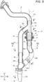
- Fig. 5 shows a cross section of the upstream portion 27A of the drain passage 27, the collector 31, the upper end portion of the downstream portion 27B of the drain passage 27, and the bypass passage 56 taken along a cutting line V-V in Fig. 3 , as viewed from the left.
- the collector 31 includes a filter cartridge 32, a case 41, a branch pipe 53, a connection hose 54, and a merging pipe 55.
- the filter cartridge 32 is a specific example of a "collector main body”
- the branch pipe 53 is a specific example of an "upper connection pipe”
- the connection hose 54 is a specific example of a "lower connection pipe”.
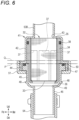
- Fig. 6 is an enlarged view of the filter cartridge 32 and the case 41 in Fig. 5 .
- the filter cartridge 32 includes a filter 33 that collects fine objects and allows the cooling water to pass therethrough, and a holder 34 that holds the filter 33.
- the filter 33 is formed of, for example, a nonwoven fabric, a resin mesh, or the like, and is formed in a bag shape in which an upper side is open and a lower side is closed.
- the holder 34 is made of resin having high heat resistance and rigidity, metal having high corrosion resistance, or the like, and is formed in a tubular shape having an axis extending in the upper-lower direction.
- a plurality of water-flowing holes 37 are provided on a peripheral wall portion of the holder 34.
- the filter 33 is disposed inside the holder 34 so as to cover the respective water-flowing holes 37 and a lower opening portion 36 of the holder 34.
- An upper portion of the filter 33 is attached and fixed to an inner peripheral surface of an upper portion of the holder 34 by, for example, an adhesive or the like.
- An O-ring 38 is provided in an annular recess formed in an outer peripheral surface of the upper portion of the holder 34.
- the O-ring 38 is in contact with an inner surface of an upper case portion 42 while pressing the inner surface thereof.
- the O-ring 38 has a function of preventing the holder 34 from coming off the upper case portion 42 so that the holder 34 does not easily fall off the upper case portion 42 when a lower case portion 45 is separated from the upper case portion 42.
- the case 41 is a member that accommodates the filter cartridge 32.
- the case 41 is made of resin having high heat resistance and rigidity, metal having high corrosion resistance, or the like, and is formed in a tubular shape having an axis extending in the upper-lower direction.
- the case 41 is divided into the upper case portion 42 that forms an upper portion of the case 41 and the lower case portion 45 that forms a lower portion of the case 41.
- a lower end portion of a first outflow pipe portion 53B of the branch pipe 53 is connected to an upper opening portion 43 of the upper case portion 42.
- the upper case portion 42 is formed integrally with the first outflow pipe portion 53B of the branch pipe 53.
- a large diameter portion 44 having an outer diameter and an inner diameter larger than those of an upper portion of the upper case portion 42 is formed at a lower portion of the upper case portion 42, and a thread is formed on an outer peripheral surface of the large diameter portion 44.
- connection pipe portion 46 is provided below the lower case portion 45, and the lower case portion 45 and the connection pipe portion 46 are integrated with each other.
- An upper end portion of the connection hose 54 is connected to a lower end portion of the connection pipe portion 46.
- a flange portion 47 having an outer diameter larger than an outer diameter of a lower portion of the lower case portion 45 is formed at an upper portion of the lower case portion 45, and the flange portion 47 is inserted into the large diameter portion 44 of the upper case portion 42.
- the lower case portion 45 is separably coupled to the upper case portion 42 by a coupling member 51. That is, the coupling member 51 that separably couples the lower case portion 45 to the upper case portion 42 is provided on an outer peripheral side of the lower case portion 45.
- the coupling member 51 is made of, for example, resin or metal and is formed in a tubular shape.
- An inner diameter of an upper portion of the coupling member 51 is substantially equal to an outer diameter of the large diameter portion 44 of the upper case portion 42, and a thread to be screwed with the thread formed in the large diameter portion 44 of the upper case portion 42 is formed on an inner surface of the upper portion of the coupling member 51.
- An inner diameter of a lower portion of the coupling member 51 is smaller than an outer diameter of the flange portion 47 of the lower case portion 45 and larger than the outer diameter of the lower portion of the lower case portion 45.
- the coupling member 51 can rotate around the lower case portion 45.
- the lower case portion 45 can be coupled and fixed to the upper case portion 42.
- the lower case portion 45 can be separated from the upper case portion 42.
- a protruding portion 48 for preventing the coupling member 51 from falling off from the lower case portion 45 when the coupling member 51 is removed from the large diameter portion 44 of the upper case portion 42 is formed on an outer peripheral surface of a lower end portion of the lower case portion 45.
- An O-ring 50 for sealing between the upper case portion 42 and the lower case portion 45 when the lower case portion 45 is coupled to the upper case portion 42 is provided on an upper surface of the lower case portion 45.
- An upper portion of the filter cartridge 32 is mounted in the upper case portion 42, and is retained in the upper case portion 42 by the O-ring 38 provided in the upper portion of the holder 34.
- a lower portion of the filter cartridge 32 is covered by the lower case portion 45, and the filter cartridge 32 is held between the upper case portion 42 and the lower case portion 45.
- the filter cartridge 32 is disposed coaxially with the case 41, a position of an upper opening portion 35 of the holder 34 of the filter cartridge 32 and a position of the upper opening portion 43 of the upper case portion 42 coincide with each other, and a position of the lower opening portion 36 of the holder 34 and a position of a lower opening portion 49 of the lower case portion 45 coincide with each other.
- a two-dot chain line P in Fig. 6 indicates a position of an upper end of the lower case portion 45 in the upper-lower direction in a state in which the lower case portion 45 is coupled to the upper case portion 42.
- a two-dot chain line Q in Fig. 6 indicates a central position of the filter cartridge 32 in the upper-lower direction in a state in which the filter cartridge 32 is held between the upper case portion 42 and the lower case portion 45, which are coupled to each other.
- the upper end of the lower case portion 45 is located below a center of the filter cartridge 32 in the upper-lower direction.
- the cooling water sequentially passes through the upper opening portion 43 of the upper case portion 42 and the upper opening portion 35 of the holder 34 from the first outflow pipe portion 53B of the branch pipe 53, and flows into the bag-shaped filter 33 disposed in the holder 34 of the filter cartridge 32.
- the cooling water flowing into the filter 33 passes through the filter 33, sequentially passes through the lower opening portion 36 of the holder 34, the lower opening portion 49 of the lower case portion 45, and the connection pipe portion 46, and flows into the connection hose 54.
- the cooling water passes through the filter 33, the fine objects in the cooling water are captured by the filter 33, and are removed from the cooling water.
- the branch pipe 53 is a pipe that connects the upstream portion 27A of the drain passage 27 and the case 41, and connects the upstream portion 27A of the drain passage 27 and the bypass passage 56.
- the branch pipe 53 is made of resin having high heat resistance and rigidity, metal having high corrosion resistance, or the like.
- the branch pipe 53 includes an inflow pipe portion 53A, the first outflow pipe portion 53B, and a second outflow pipe portion 53C.
- the inflow pipe portion 53A is located on an upper side, and the first outflow pipe portion 53B is located on a lower side.
- the inflow pipe portion 53A and the first outflow pipe portion 53B are coaxially disposed, and a portion of the branch pipe 53 from the inflow pipe portion 53A to the first outflow pipe portion 53B extends linearly in the upper-lower direction.
- An upper end portion of the inflow pipe portion 53A is connected to a lower end portion of the upstream portion 27A of the drain passage 27, and the lower end portion of the first outflow pipe portion 53B is connected to the upper opening portion 43 of the upper case portion 42 (in the present embodiment, as described above, the first outflow pipe portion 53B and the upper case portion 42 are integrally formed).
- the inflow pipe portion 53A is disposed coaxially with the lower end portion of the upstream portion 27A of the drain passage 27, and the first outflow pipe portion 53B is disposed coaxially with the case 41.
- the second outflow pipe portion 53C extends forward while being inclined downward from a substantially middle portion in the upper-lower direction of a portion of the branch pipe 53 from the inflow pipe portion 53A to the first outflow pipe portion 53B.
- An upper end portion of a bypass pipe 57 forming an upper portion of the bypass passage 56 is connected to a lower end portion of the second outflow pipe portion 53C.
- the connection hose 54 is a pipe that connects the case 41 and a first inflow pipe portion 55A of the merging pipe 55.
- the connection hose 54 is formed of a rubber hose having high heat resistance and rigidity.
- a reinforcing fiber-containing rubber hose having an outer diameter of 34 mm, a hose wall thickness of 3.5 mm, and a rubber hardness of 65 to 75 (durometer A hardness) is used as the connection hose 54.
- the connection hose 54 has flexibility, the connection hose 54 is hard to bend because the connection hose 54 has high rigidity.
- connection hose 54 An upper end portion of the connection hose 54 is connected to the lower end portion of the connection pipe portion 46 formed integrally with the lower case portion 45. A lower end portion of the connection hose 54 is connected to the upper end portion of the first inflow pipe portion 55A of the merging pipe 55. In addition, the upper end portion of the connection hose 54 is disposed coaxially with the case 41.
- connection hose 54 an upper bent portion 54A is provided between the upper end portion and the lower end portion thereof, and a lower bent portion 54B is provided between the upper bent portion 54A and the lower end portion thereof.
- the upper bent portion 54A and the lower bent portion 54B have a function of facilitating bending of the connection hose 54 when the lower case portion 45 is moved downward to be separated from the upper case portion 42.
- the lower bent portion 54B is disposed substantially at a center between the upper end portion and the lower end portion of the connection hose 54
- the upper bent portion 54A is disposed substantially at a center between the upper end portion of the connection hose 54 and the lower bent portion 54B.
- connection hose 54 extends downward from the upper end portion thereof along an axis J of the case 41, bends at the upper bent portion 54A, extends downward while being inclined with respect to the axis J so as to be separated from the axis J, bends at the lower bent portion 54B, and then extends downward while being inclined with respect to the axis J so as to be close to the axis J.
- a portion of the connection hose 54 extending from the upper bent portion 54A to the lower bent portion 54B extends downward while being inclined rearward of the engine 2 and toward a center side (right side) of the engine 2 in the left-right direction.
- a portion of the connection hose 54 from the lower bent portion 54B to the lower end portion thereof extends downward while being inclined leftward and forward.
- connection hose 54 includes the upper bent portion 54A and the lower bent portion 54B as described above, a portion of the connection hose 54 from an upper end thereof to the upper bent portion 54A extends downward along the axis J of the case 41, a portion of the connection hose 54 from the upper bent portion 54A to the lower bent portion 54B extends downward while being inclined with respect to the axis J, and a portion of the connection hose 54 from the lower bent portion 54B to the lower end portion thereof extends downward while being inclined with respect to the axis J. Therefore, the connection hose 54 extends in the upper-lower direction between the case 41 and the merging pipe 55 as a whole.
- the upper bent portion 54A is a specific example of a "first bent portion”
- the lower bent portion 54B is a specific example of a "second bent portion”.
- the merging pipe 55 is a pipe that connects the connection hose 54 and the downstream portion 27B of the drain passage 27, and connects the bypass passage 56 and the downstream portion 27B of the drain passage 27.
- the merging pipe 55 is made of resin having high heat resistance and rigidity, metal having high corrosion resistance, or the like.
- the merging pipe 55 includes the first inflow pipe portion 55A, a second inflow pipe portion 55B, and an outflow pipe portion 55C.
- the second inflow pipe portion 55B is located on an upper side thereof, and the outflow pipe portion 55C is located on a lower side thereof.
- the second inflow pipe portion 55B and the outflow pipe portion 55C are coaxially disposed, and a portion of the merging pipe 55 from the second inflow pipe portion 55B to the outflow pipe portion 55C linearly extends in the upper-lower direction.
- a lower end portion of a connection pipe 58 forming a lower portion of the bypass passage 56 is connected to an upper end portion of the second inflow pipe portion 55B, and a lower end portion of the outflow pipe portion 55C is connected to an upper end portion of the downstream portion 27B (drain hole 30) of the drain passage 27.
- the first inflow pipe portion 55A extends rearward while being inclined rightward and upward from a substantially middle portion in the upper-lower direction of a portion of the merging pipe 55 from the second inflow pipe portion 55B to the outflow pipe portion 55C.
- the lower end portion of the connection hose 54 is connected to the upper end portion of the first inflow pipe portion 55A.
- the inner diameters of the inflow pipe portion 53A of the branch pipe 53, the first outflow pipe portion 53B of the branch pipe 53, the connection hose 54, and the first inflow pipe portion 55A of the merging pipe 55 are substantially equal to each other.
- the bypass passage 56 is provided between the upstream portion 27A and the downstream portion 27B of the drain passage 27.
- the bypass passage 56 is connected in parallel with a passage formed by the filter cartridge 32, the case 41, and the connection hose 54 between the upstream portion 27A and the downstream portion 27B of the drain passage 27.
- the bypass passage 56 is a passage for allowing the cooling water to smoothly flow from the upstream portion 27A to the downstream portion 27B of the drain passage 27 in a case where a large amount of fine objects are accumulated in the filter 33 and the filter 33 is clogged.
- the bypass passage 56 is formed by the bypass pipe 57 and the connection pipe 58.
- the bypass pipe 57 is formed of a hose made of rubber having high heat resistance and rigidity, a pipe made of resin having high heat resistance and rigidity, a pipe made of metal having high corrosion resistance, or the like.
- the upper end portion of the bypass pipe 57 is connected to the lower end portion of the second outflow pipe portion 53C of the branch pipe 53, and a lower end portion of the bypass pipe 57 is connected to an upper end portion of the connection pipe 58.
- the bypass pipe 57 extends downward from the upper end thereof while being inclined forward with respect to the axis J of the case 41, bents, and then extends in the upper-lower direction so as to be parallel to the axis J of the case 41.
- connection pipe 58 is made of resin having high heat resistance and rigidity, metal having high corrosion resistance, or the like.
- the lower end portion of the connection pipe 58 is connected to the upper end portion of the second inflow pipe portion 55B of the merging pipe 55.
- the connection pipe 58 extends in the upper-lower direction and is disposed coaxially with the bypass pipe 57.
- the inner diameters of the second outflow pipe portion 53C of the branch pipe 53, the bypass pipe 57, the connection pipe 58, and the second inflow pipe portion 55B of the merging pipe 55 are substantially equal to each other.
- the inner diameters of the second outflow pipe portion 53C of the branch pipe 53, the bypass pipe 57, the connection pipe 58, and the second inflow pipe portion 55B of the merging pipe 55 are substantially equal to the inner diameters of the inflow pipe portion 53A of the branch pipe 53, the first outflow pipe portion 53B of the branch pipe 53, the connection hose 54, and the first inflow pipe portion 55A of the merging pipe 55.
- the cooling water flows into the inflow pipe portion 53A of the branch pipe 53 from the upstream portion 27A of the drain passage 27.
- the inflow pipe portion 53A of the branch pipe 53, the first outflow pipe portion 53B of the branch pipe 53, and the case 41 are coaxially disposed, and a flow path from the inflow pipe portion 53A of the branch pipe 53 to the case 41 extends linearly in the upper-lower direction.
- the second outflow pipe portion 53C of the branch pipe 53 is inclined with respect to the inflow pipe portion 53A of the branch pipe 53, and a flow path from the inflow pipe portion 53A of the branch pipe 53 to the bypass pipe 57 is bent.
- a flow path from the upstream portion 27A of the drain passage 27 to the downstream portion 27B of the drain passage 27 through the inflow pipe portion 53A of the branch pipe 53, the first outflow pipe portion 53B of the branch pipe 53, the case 41, the connection hose 54, the first inflow pipe portion 55A of the merging pipe 55, and the outflow pipe portion 55C of the merging pipe 55 does not have a large bent portion.
- the cooling water smoothly flows from the upstream portion 27A of the drain passage 27 to the downstream portion 27B of the drain passage 27 through the inflow pipe portion 53A of the branch pipe 53, the first outflow pipe portion 53B of the branch pipe 53, the case 41, the connection hose 54, the first inflow pipe portion 55A of the merging pipe 55, and the outflow pipe portion 55C of the merging pipe 55.
- the cooling water flowing into the bypass pipe 57 sequentially passes through the bypass pipe 57 and the connection pipe 58, flows into the second inflow pipe portion 55B of the merging pipe 55 as indicated by an arrow F, and subsequently flows into the downstream portion 27B of the drain passage 27 from the outflow pipe portion 55C of the merging pipe 55 as indicated by the arrow D.
- the user By performing navigation of a ship using the outboard motor 1, fine objects are captured by the filter 33 of the collector 31, and the captured fine objects are accumulated in the filter 33. Therefore, the user removes the fine objects accumulated in the filter 33 after using the outboard motor 1. After the outboard motor 1 is used for a long period of time, the user replaces the filter cartridge 32. When such maintenance of the collector 31 is performed, the user separates the lower case portion 45 from the upper case portion 42 and removes the filter cartridge 32 from the upper case portion 42.
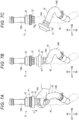
- Figs. 7A and 7C show a method of removing the filter cartridge 32 from the upper case portion 42 by separating the lower case portion 45 from the upper case portion 42.
- the user rotates the coupling member 51 of the case 41 in a direction in which the screwing is released, and removes the coupling member 51 from the large diameter portion 44 of the upper case portion 42.
- the user grips the upper portion of the connection hose 54 with his/her hand and pushes down the connection hose 54 as indicated by an arrow K in Fig. 7A .
- the lower case portion 45 moves downward, and as shown in Fig. 7B , the lower case portion 45 is separated from the upper case portion 42.
- the user pushes and moves the upper portion of the connection hose 54 in a direction separated from the engine 2 (substantially leftward) as indicated by an arrow L in Fig. 7B , and moves the lower case portion 45 to a position deviated from directly below the upper case portion 42.
- Fig. 7C after the lower case portion 45 is moved to a position deviated from directly below the upper case portion 42, the user pulls down the filter cartridge 32 mounted on the upper case portion 42 as shown by an arrow M in Fig. 7C and removes the filter cartridge 32 from the upper case portion 42.
- the user removes the fine objects accumulated in the filter 33, mounts the filter cartridge 32 from which the fine objects have been removed on the upper case portion 42, or mounts a new filter cartridge 32 on the upper case portion 42, and then mounts the lower case portion 45 to the upper case portion 42 to couple the lower case portion 45 to the upper case portion 42.
- connection hose 54 has flexibility, the connection hose 54 is hard to bend because of its high rigidity.
- the user can grip and push down the upper portion of the connection hose 54 by hands to separate the lower case portion 45 from the upper case portion 42. This point will be described below.
- connection hose extends linearly in the upper-lower direction from the case 41 to the first inflow pipe portion 55A of the merging pipe 55, it is difficult for the user to push down the connection hose even if the user grips the upper portion of the connection hose with his/her hand and applies a downward force, and it is difficult to separate the lower case portion 45 from the upper case portion 42.
- One of the reasons is that a direction of the force applied to the connection hose coincides with an extending direction of the connection hose, and thus the connection hose is extremely difficult to bend.
- connection hose 54 is provided with the upper bent portion 54A and the lower bent portion 54B, and the portion of the connection hose 54 from the upper bent portion 54A to the lower bent portion 54B and the portion of the connection hose 54 from the lower bent portion 54B to the lower end portion extend in a direction intersecting the axis J of the case 41 extending in the upper-lower direction.
- connection hose 54 is more easily bent than in the case where the connection hose 54 extends linearly in the upper-lower direction as described above. Therefore, the user can easily push down the connection hose 54 by gripping the upper portion of the connection hose 54 with his/her hand and applying the downward force, and can easily separate the lower case portion 45 from the upper case portion 42.
- Fig. 8 shows a cross section of the connection hose 54 and the bypass pipe 57 cut along a cutting line VIII-VIII in Fig. 5 as viewed from above.
- an axis N of a portion of the connection hose 54 from the upper bent portion 54A to the lower bent portion 54B intersects a straight line T that passes through both an axial center U of the upper end portion of the connection hose 54 and an axial center V of a portion of the bypass pipe 57 excluding the inclined upper end portion.
- connection hose 54 and the bypass pipe 57 are disposed in this manner, the lower bent portion 54B and the like of the connection hose 54 do not come into contact with the bypass pipe 57.
- the lower case portion 45 separated from the upper case portion 42 does not come into contact with the bypass pipe 57 as indicated by a two-dot chain line in Fig. 8 .
- the two-dot chain line in Fig. 8 shows the lower case portion 45 in a state of being pushed and moved to a position shown in Fig. 7C .
- the case 41 accommodating the filter cartridge 32 is formed in a tubular shape having the axis extending in the upper-lower direction, the upstream portion 27A of the drain passage 27 and the case 41 are connected by the inflow pipe portion 53A and the first outflow pipe portion 53B of the branch pipe 53 extending in the upper-lower direction, and the case 41 and the downstream portion 27B of the drain passage 27 are connected by the connection hose 54 extending in the upper-lower direction as viewed as a whole, although the connection hose 54 includes the bent portions 54A and 54B.
- the flow path of the cooling water in the collector 31 provided between the upstream portion 27A of the drain passage 27 and the downstream portion 27B of the drain passage 27 is not largely bent, unlike the flow path of the related art shown in Fig. 9B . Therefore, it is possible to prevent an increase in a pressure loss in the flow path of the cooling water in the collector 31, and it is possible to improve the flow of the cooling water in the collector 31.
- connection hose 54 is provided with the upper bent portion 54A and the lower bent portion 54B, and the portion of the connection hose 54 from the upper bent portion 54A to the lower bent portion 54B and the portion of the connection hose 54 from the lower bent portion 54B to the lower end portion are inclined with respect to the axis J of the case 41 extending in the upper-lower direction. Therefore, when the user grips the upper portion of the connection hose 54 with his/her hand and applies a downward force, the user can easily bend the connection hose 54 and can easily separate the lower case portion 45 from the upper case portion 42 by moving the lower case portion 45 connected to the upper end portion of the connection hose 54 downward. As a result, the user can easily perform maintenance of the collector 31.
- connection hose 54 In the connection hose 54, the portion thereof from the upper bent portion 54A to the lower bent portion 54B extends downward while being inclined rearward of the engine 2 and toward the center side of the engine 2 in the left-right direction. Accordingly, it is possible to prevent a portion of the connection hose 54, for example, the lower bent portion 54B, from protruding outward in a lateral direction of the engine 2. Therefore, it is possible to reduce the size of the engine top cover 8 that covers the engine 2 in which the collector 31 is disposed, and it is possible to reduce the size of the outboard motor 1.
- the upper end of the lower case portion 45 is located below the center of the filter cartridge 32 in the upper-lower direction. Accordingly, when the lower case portion 45 is separated from the upper case portion 42, an amount of downward movement of the lower case portion 45 can be reduced. Therefore, it is possible to further facilitate an operation of removing the filter cartridge 32 from the upper case portion 42 by separating the lower case portion 45 from the upper case portion 42.
- connection hose 54 and the bypass pipe 57 when the connection hose 54 and the bypass pipe 57 are viewed from above, the axis N of the portion of the connection hose 54 from the upper bent portion 54A to the lower bent portion 54B intersects the straight line T that passes through both the axial center U of the upper end portion of the connection hose 54 and the axial center V of the portion of the bypass pipe 57 excluding the inclined upper end portion.
- the lower bent portion 54B and the like of the connection hose 54 can be prevented from coming into contact with the bypass pipe 57.
- the lower case portion 45 is separated from the upper case portion 42 and the filter cartridge 32 is removed from the upper case portion 42, it is possible to prevent the lower case portion 45 separated from the upper case portion 42 from coming into contact with the bypass pipe 57.
- the cooling device 21 including the collector 31 capable of collecting the microplastic is provided in the outboard motor 1, it is possible to collect the microplastic diffused in seawater, lake water, river water, or the like at the same time as sailing of the ship, and clean the sea, lake, or river.
- connection hose 54 and the lower case portion 45 unseparably connected to the upper end portion of the connection hose 54 are moved downward together to allow the filter cartridge 32 to be removable from the case 41, but the present disclosure is not limited thereto.
- the case 41 and the branch pipe 53 may be separably connected
- the case 41 and the connection hose 54 may be separably connected
- only the upper end portion of the connection hose 54 may be pushed downward to separate the case 41 from both the branch pipe 53 and the connection hose 54. This makes it possible to remove the entire case 41 from the outboard motor 1 and remove fine objects accumulated in the filter 33.
- the collector 31 is disposed on the left side of the rear portion of the engine 2 in the above embodiment, the collector 31 may be disposed at another position around the engine 2, such as on the right side of the rear portion of the engine 2.
- the power source of the outboard motor 1 is not limited to the engine, and may be an electric motor.
- the cooling device of the present disclosure is not limited to the outboard motor, and may be provided in other types of ship propulsion machines such as an inboard-outboard motor or an inboard motor.
Landscapes
- Engineering & Computer Science (AREA)
- Chemical & Material Sciences (AREA)
- Combustion & Propulsion (AREA)
- Mechanical Engineering (AREA)
- Ocean & Marine Engineering (AREA)
- General Engineering & Computer Science (AREA)
- Exhaust Silencers (AREA)
Abstract
Description
- The present disclosure relates to a cooling device for a ship propulsion machine having a function of collecting fine objects diffused in water such as seawater and lake water.
- In recent years, there has been a problem of contamination of sea, lake, rivers, and the like caused by diffusion of fine waste such as microplastic into water such as seawater, lake water, or river water. It is known that sea, lake, river, and the like are polluted by dregs of feed used for aquaculture diffused in water such as seawater, lake water or river water. In order to prevent such contamination, it is desired to collect and recover fine waste such as microplastic, dregs of feed, and the like (hereinafter, referred to as "fine objects").
-
Patent Literature 1 listed below describes an outboard motor in which a cooling device having a function of collecting fine objects is mounted. The cooling device uses a pump to take water such as seawater or lake water into the outboard motor, and supplies the taken water as cooling water to a water jacket provided in an engine of the outboard motor. The cooling water supplied to the water jacket flows through the water jacket, thereby cooling the engine. In addition, the cooling water after flowing through the water jacket flows through a drain pipe, passes through the inside of a filter device provided in the middle of the drain pipe, and is then discharged to the outside of the outboard motor. When the cooling water passes through the filter device, the fine objects in the cooling water are captured by the filter device and removed from the cooling water. In this way, according to the cooling device, seawater, lake water, or the like can be taken into the outboard motor, and fine objects contained in the taken seawater, lake water, or the like can be collected by the filter device. - Patent Literature 1:
JP2020-163872A -
Fig. 9A shows a drain pipe and a filter device in a cooling device shown inFig. 3 ofPatent Literature 1. InFig. 9A , areference numeral 133 denotes the drain pipe, and areference numeral 135 denotes the filter device.Fig. 9B shows a state in which thedrain pipe 133 and thefilter device 135 inFig. 9A are viewed from a direction indicated by an arrow S inFig. 9A . InFigs. 9A and 9B , arrows X indicate a flow direction of the cooling water in thedrain pipe 133 and thefilter device 135. As shown inFig. 9B , in the cooling device ofPatent Literature 1, since the cooling water flows while being largely bent in thefilter device 135, a pressure loss in the flow path of the cooling water increases, and the flow of the cooling water may deteriorate. - Therefore, in order to prevent an increase in the pressure loss in the flow path of the cooling water, as shown in
Fig. 10 , a method is conceivable in which a drain passage for supplying the cooling water after flowing through the water jacket to a water discharge port of the outboard motor is divided into an upperdrain passage portion 201 and a lowerdrain passage portion 202, and afilter device 203 is disposed between the upperdrain passage portion 201 and the lowerdrain passage portion 202 coaxially with the upperdrain passage portion 201 and the lowerdrain passage portion 202. According to this method, as indicated by arrows Y inFig. 10 , the cooling water flows linearly through the upperdrain passage portion 201, thefilter device 203, and the lowerdrain passage portion 202, and therefore it is possible to prevent an increase in a pressure loss in the flow path of the cooling water, and it is possible to improve the flow of the cooling water. - However, when the
filter device 203 is disposed between the upperdrain passage portion 201 and the lowerdrain passage portion 202 coaxially with the upperdrain passage portion 201 and the lowerdrain passage portion 202, it is difficult to remove thefilter device 203 from between the upperdrain passage portion 201 and the lowerdrain passage portion 202, which makes it difficult to perform maintenance of the filter device 203 (for example, removal of fine objects accumulated in a filter or the like). - That is, a lower end portion of the upper
drain passage portion 201 is inserted into and fitted to an upper portion of thefilter device 203, and an upper end portion of the lowerdrain passage portion 202 is inserted into and fitted to a lower portion of thefilter device 203. Therefore, in order to remove thefilter device 203 from between the upperdrain passage portion 201 and the lowerdrain passage portion 202, it is necessary to move thefilter device 203 in an upper-lower direction with respect to the upperdrain passage portion 201 or the lowerdrain passage portion 202 by moving thefilter device 203 downward with respect to the lower end portion of the upperdrain passage portion 201 so that the upperdrain passage portion 201 and thefilter device 203 can be separated from each other, or by moving thefilter device 203 upward with respect to the upper end portion of the lowerdrain passage portion 202 so that the lowerdrain passage portion 202 and thefilter device 203 can be separated from each other, for example. However, when the upperdrain passage portion 201 and the lowerdrain passage portion 202 are pipes, hoses, or the like having high rigidity, it is difficult to move thefilter device 203 sandwiched between the upperdrain passage portion 201 and the lowerdrain passage portion 202 upward and downward. Therefore, it is difficult to remove thefilter device 203 from between the upperdrain passage portion 201 and the lowerdrain passage portion 202. - In this regard, if a rubber hose or the like having low rigidity is used as the upper
drain passage portion 201 or the lowerdrain passage portion 202, thefilter device 203 can be easily removed from between the upperdrain passage portion 201 and the lowerdrain passage portion 202 by bending the rubber hose by hands. However, the upperdrain passage portion 201 and the lowerdrain passage portion 202 need to have improved durability against vibration, an impact, heat, or the like. For this reason, even when a rubber hose is used as the upperdrain passage portion 201 or the lowerdrain passage portion 202, it is necessary to use, for example, a rubber hose containing reinforcing fibers or a thick rubber hose, and as a result, the rigidity of the rubber hose is increased. That is, in order to meet the need to increase the durability of the upperdrain passage portion 201 and the lowerdrain passage portion 202, it is difficult to use a rubber hose or the like having low rigidity that can be easily bent by hands as the upperdrain passage portion 201 or the lowerdrain passage portion 202. - The present disclosure has been made in view of, for example, the above-described problems, and an object of the present disclosure is to provide a cooling device for a ship propulsion machine capable of facilitating maintenance of a collector (filter device) that collects fine objects while preventing deterioration of a flow of cooling water.
- In order to solve the above problem, there is provided a cooling device for a ship propulsion machine, the cooling device being provided in the ship propulsion machine, taking water of an outside of the ship propulsion machine into the ship propulsion machine, cooling a power source of the ship propulsion machine by flowing the taken water around or inside the power source as cooling water, and discharging the cooling water after flowing around or inside the power source to outside of the ship propulsion machine, the cooling device including: a drain passage configured to discharge the cooling water after flowing around or inside the power source to the outside of the ship propulsion machine; and a collector provided between an upstream portion and a downstream portion of the drain passage and configured to collect a fine object contained in the cooling water flowing from the upstream portion of the drain passage toward the downstream portion of the drain passage. The collector includes a collector main body configured to collect the fine object, through which the cooling water passes, a case having a tubular shape having an axis extending in an upper-lower direction and accommodating the collector main body, an upper connection pipe extending in the upper-lower direction, whose upper end portion is connected to the upstream portion of the drain passage, whose lower end portion is connected to an upper portion of the case, and through which the cooling water flows from the upstream portion of the drain passage into the case, and a lower connection pipe having flexibility, whose upper end portion is connected to a lower portion of the case, whose lower end portion is connected to the downstream portion of the drain passage, and through which the cooling water flows from the case into the downstream portion of the drain passage. A first bent portion is provided between the upper end portion and the lower end portion of the lower connection pipe. A second bent portion is provided between the first bent portion and the lower end portion of the lower connection pipe. The lower connection pipe extends downward from the upper end portion thereof along an axis of the case, bends at the first bent portion, extends downward while being inclined with respect to the axis so as to be separated from the axis, bends at the second bent portion, and extends downward while being inclined with respect to the axis so as to be close to the axis.
- According to the present disclosure, it is possible to facilitate maintenance of a collector that collects fine objects while preventing deterioration of the flow of cooling water.
-
-
Fig. 1 is an overall view showing an outboard motor provided with a cooling device according to an embodiment of the present disclosure. -
Fig. 2 is an external view showing an engine of the outboard motor according to the embodiment of the present disclosure as viewed from the left. -
Fig. 3 is an external view showing the engine inFig. 2 as viewed from the rear. -
Fig. 4 is an explanatory view showing a configuration of the cooling device according to the embodiment of the present disclosure. -
Fig. 5 is a sectional view showing an upstream portion of a drain passage, a collector, a downstream portion of the drain passage, and a bypass passage, which is taken along a cutting line V-V inFig. 3 . -
Fig. 6 is an enlarged sectional view showing a case and a filter cartridge shown inFig. 5 . -
Figs. 7A and 7C are explanatory views showing a method of removing the filter cartridge from an upper case portion by separating a lower case portion from the upper case portion in the embodiment of the present disclosure. -
Fig. 8 is a sectional view showing a connection hose, a bypass pipe, and the like taken along a cutting line VIII-VIII inFig. 5 , as viewed from above. -
Figs. 9A and 9B are explanatory views showing a drain pipe and a filter device in a cooling device of the related art. -
Fig. 10 is an explanatory view showing the filter device and a drain passage portion disposed coaxially with each other. - A cooling device for a ship propulsion machine according to an embodiment of the present disclosure is a cooling device that is provided in the ship propulsion machine, takes water outside the ship propulsion machine into the ship propulsion machine, cools a power source of the ship propulsion machine by flowing the taken water to around or inside the power source as cooling water, and discharges the cooling water after flowing around or inside the power source to outside of the ship propulsion machine. The cooling device includes a drain passage for discharging the cooling water after flowing around or inside the power source to the outside of the ship propulsion machine, and a collector provided between an upstream portion and a downstream portion of the drain passage and configured to collect a fine object contained in the cooling water flowing from the upstream portion of the drain passage toward the downstream portion of the drain passage.
- The collector includes a collector main body that collects the fine object and allows the cooling water to pass therethrough, a case that is formed in a tubular shape having an axis extending in an upper-lower direction and accommodates the collector main body, an upper connection pipe that extends in the upper-lower direction, whose upper end portion is connected to the upstream portion of the drain passage, whose lower end portion is connected to an upper portion of the case, and through which the cooling water flows from the upstream portion of the drain passage into the case, and a lower connection pipe that has flexibility, whose upper end portion is connected to a lower portion of the case, whose lower end portion is connected to the downstream portion of the drain passage, and through which the cooling water flows from the case into the downstream portion of the drain passage.
- A first bent portion is provided between the upper end portion and the lower end portion of the lower connection pipe, and a second bent portion is provided between the first bent portion and the lower end portion of the lower connection pipe. Further, the lower connection pipe extends downward from the upper end portion thereof along an axis of the case, bends at the first bent portion, extends downward while being inclined with respect to the axis so as to be separated from the axis, bends at the second bent portion, and then extends downward while being inclined with respect to the axis so as to be close to the axis.
- In the cooling device of the present embodiment, the case is formed in a tubular shape having the axis extending in the upper-lower direction, and the upper connection pipe extends in the upper-lower direction between the upstream portion of the drain passage and the case. Although the lower connection pipe includes the first bent portion and the second bent portion, a portion of the lower connection pipe from the upper end portion to the first bent portion extends downward along the axis of the case, a portion of the lower connection pipe from the first bent portion to the second bent portion extends downward while being inclined with respect to the axis of the case, and a portion of the lower connection pipe from the second bent portion to the lower end portion extends downward while being inclined with respect to the axis of the case. Therefore, the lower connection pipe extends in the upper-lower direction between the case and the downstream portion of the drain passage as a whole. As described above, a flow path of the cooling water in the collector provided between the upstream portion of the drain passage and the downstream portion of the drain passage is not greatly bent, unlike the flow path of the related art shown in
Fig. 9B . Therefore, it is possible to prevent an increase in a pressure loss in the flow path of the cooling water in the collector, and it is possible to improve the flow of the cooling water in the collector. - In addition, in the collector of the cooling device of the present embodiment, the first bent portion and the second bent portion are provided in the lower connection pipe, and the portion of the lower connection pipe from the first bent portion to the second bent portion and the portion of the lower connection pipe from the second bent portion to the lower end portion are inclined with respect to the axis of the case extending in the upper-lower direction. Therefore, when the user grips an upper portion of the lower connection pipe with his/her hand and applies a downward force, the user can easily bend the lower connection tube and easily move the upper end portion of the lower connection pipe downward. For example, when the upper end portion of the lower connection pipe is moved downward so that the case can be removed from the upper connection pipe and the lower connection pipe, or when the upper end portion of the lower connection pipe is moved downward so that a part of the case can be separated from the case, the user can easily perform maintenance of the collector main body accommodated in the case (for example, removal of fine objects accumulated in the collector main body).
- Hereinafter, an embodiment of a cooling device for a ship propulsion machine according to the present disclosure will be described with reference to
Figs. 1 to 8 . Note that in this embodiment, front (Fd), rear (Bd), upper (Ud), lower (Dd), left (Ld), and right (Rd) directions are described following arrows drawn at a lower left inFigs. 1 to 8 . -
Fig. 1 shows an entireoutboard motor 1, which is an embodiment of a ship propulsion machine, as viewed from the left. As shown inFig. 1 , theoutboard motor 1 includes anengine 2 as a power source, adrive shaft 3 that rotates by receiving power of theengine 2, apropeller 4 that generates a propulsive force of a ship, apropeller shaft 5 to which thepropeller 4 is attached, and agear mechanism 6 that transmits the rotation of thedrive shaft 3 to thepropeller shaft 5. Although not shown, thegear mechanism 6 is provided with a shift device that switches the direction of rotation transmitted from thedrive shaft 3 to thepropeller shaft 5. Theengine 2 is disposed at an upper portion of theoutboard motor 1. Thegear mechanism 6, thepropeller shaft 5, and thepropeller 4 are disposed at a lower portion of theoutboard motor 1. Thedrive shaft 3 extends in an upper-lower direction between theengine 2 and thegear mechanism 6. - A lower portion of the
engine 2 is covered with anengine bottom cover 7, and a middle portion and an upper portion of theengine 2 in the upper-lower direction are covered with anengine top cover 8. Theengine top cover 8 is detachably attached to theengine bottom cover 7. By removing theengine top cover 8, it is possible to expose a wide range of theengine 2 from the middle portion to the upper portion in the upper-lower direction. In addition, an upper portion of thedrive shaft 3 is covered with anupper case 9, and a middle portion of thedrive shaft 3 in the upper-lower direction is covered with amiddle case 10. A lower portion of thedrive shaft 3, thegear mechanism 6, and a front portion of thepropeller shaft 5 are covered with alower case 11. -
Fig. 2 shows theengine 2 as viewed from the left.Fig. 3 shows theengine 2 as viewed from the rear. Theengine 2 is, for example, a four-cycle four-cylinder gasoline engine, and a cooling method of theengine 2 is a water cooling method. Theengine 2 is disposed such that an extending direction of a crankshaft is the upper-lower direction. As shown inFig. 2 , in theengine 2, acrankcase 12 is disposed in a front portion, acylinder block 13 is disposed behind thecrankcase 12, and acylinder head 14 is disposed behind thecylinder block 13. A rear portion of thecylinder head 14 is covered with acylinder head cover 15. - As shown in
Fig. 1 , theoutboard motor 1 is provided with anexhaust passage 16 for discharging exhaust gas discharged from theengine 2 to the outside of theoutboard motor 1. An upper end side of theexhaust passage 16 is connected to an exhaust port provided in thecylinder head 14 of theengine 2, and a lower end side of theexhaust passage 16 is connected to anexhaust chamber 17 provided at a rear portion of a lower portion of theoutboard motor 1. In theoutboard motor 1 of the present embodiment, theexhaust chamber 17 is provided in a portion from a rear portion in themiddle case 10 to a rear portion in thelower case 11. The exhaust gas discharged from the exhaust port of theengine 2 is sent to theexhaust chamber 17 via theexhaust passage 16, and then discharged to the outside of theoutboard motor 1 via, for example, a discharge port provided in a shaft portion of thepropeller 4. InFigs. 2 and3 , the exhaust port of theengine 2 and theexhaust passage 16 are not shown. - The
outboard motor 1 includes acooling device 21 for cooling theengine 2 and other heat generating portions in theoutboard motor 1 by using water around theoutboard motor 1, such as seawater, lake water, or river water, as cooling water.Fig. 4 shows a configuration of thecooling device 21. - As shown in
Fig. 4 , thecooling device 21 includes awater intake port 22, a water intake passage 23, awater pump 24, awater supply passage 25, awater jacket 26, adrain passage 27, athermostat 28, apressure valve 29, and acollector 31. - The
water intake port 22 is a port through which water around theoutboard motor 1 is taken into theoutboard motor 1, and is provided in a portion of theoutboard motor 1 that is submerged below water, specifically, in a part of the lower case 11 (seeFig. 1 ). In addition, thewater intake port 22 is provided with a strainer or a cover having a large number of small holes for preventing an object larger than a fine object, such as a stone or algae, from entering theoutboard motor 1 together with seawater, lake water, river water, or the like. - The water intake passage 23 is a passage for causing the
water pump 24 to absorb water taken into theoutboard motor 1 from thewater intake port 22, and is provided inside thelower case 11. - The
water pump 24 is a pump that absorbs water taken into theoutboard motor 1 from thewater intake port 22 and discharges the absorbed water as the cooling water, and is provided, for example, inside thelower case 11 or themiddle case 10. Further, thewater pump 24 is operated by utilizing the rotation of thedrive shaft 3. - The
water supply passage 25 is a passage for supplying the cooling water discharged from thewater pump 24 to thewater jacket 26, and is formed of, for example, a hose, a pipe, or the like provided inside themiddle case 10, theupper case 9, and theengine bottom cover 7. - The
water jacket 26 is a mechanism that cools theengine 2 by causing the cooling water supplied through thewater supply passage 25 to flow around or inside theengine 2, and is provided around or inside theengine 2. - The
drain passage 27 is a passage for discharging the cooling water after flowing through thewater jacket 26 to the outside of theoutboard motor 1, and is formed of, for example, a hose or a pipe provided inside theengine top cover 8, theengine bottom cover 7, theupper case 9, and the like. As shown inFig. 2 , an upstream end portion of thedrain passage 27 is connected to anoutlet 26A of thewater jacket 26 disposed in an upper portion of thecylinder head 14. In addition, thedrain passage 27 extends from theoutlet 26A of thewater jacket 26 to an upper left side of a rear portion of theengine 2, passes through thecollector 31, and then extends downward inside theengine bottom cover 7 and theupper case 9. As shown inFig. 4 , a downstream end portion of thedrain passage 27 is connected to theexhaust chamber 17. - The
thermostat 28 is a device that limits the flow of the cooling water in order to warm up theengine 2 or in order to prevent supercooling of theengine 2, and is provided, for example, in the vicinity of theoutlet 26 of thewater jacket 26. Thethermostat 28 opens when a temperature of the cooling water flowing through thewater jacket 26 becomes equal to or higher than a predetermined reference temperature, and closes when the temperature of the cooling water becomes lower than the reference temperature. - The
pressure valve 29 is a valve for lowering a water pressure in thewater supply passage 25 or thewater jacket 26 by releasing the cooling water discharged from thewater pump 24 to theexhaust chamber 17 side when the flow of the cooling water is limited by thethermostat 28. Thepressure valve 29 is, for example, a normally closed valve, and is opened when the water pressure in thewater supply passage 25 exceeds a predetermined reference pressure. - The
collector 31 is a device that collects fine objects contained in the cooling water flowing through thedrain passage 27. Thecollector 31 will be described in detail later. - In the
cooling device 21 having such a configuration, when thewater pump 24 is operated, thethermostat 28 is opened, and thepressure valve 29 is closed, water around theoutboard motor 1 is taken into theoutboard motor 1 from thewater intake port 22, flows through the water intake passage 23 and thewater supply passage 25 in sequence, and is sent to thewater jacket 26 as the cooling water. The cooling water sent to thewater jacket 26 flows through thewater jacket 26, thereby cooling theengine 2. The cooling water flowing through thewater jacket 26 flows into thedrain passage 27 from theoutlet 26A of thewater jacket 26, flows through thedrain passage 27, passes through thecollector 31 in the middle, and is then discharged into theexhaust chamber 17. The cooling water discharged into theexhaust chamber 17 is discharged together with the exhaust gas to the outside of theoutboard motor 1 via, for example, the discharge port provided in the shaft portion of thepropeller 4. On the other hand, when thewater pump 24 is operated, thethermostat 28 is closed, and thepressure valve 29 is opened, the water taken into theoutboard motor 1 from thewater intake port 22 sequentially flows through the water intake passage 23 and thewater supply passage 25, but before reaching thewater jacket 26, the water is sent to theexhaust chamber 17 side via the openedpressure valve 29 and discharged into theexhaust chamber 17. The cooling water discharged into theexhaust chamber 17 is discharged to the outside of theoutboard motor 1 together with the exhaust gas. - As described above, the
collector 31 is a device that collects fine objects contained in the cooling water flowing through thedrain passage 27. The fine objects are, for example, fine waste such as microplastic, dregs of feed used for aquaculture, or the like. A size of the fine object is, for example, about 0.1 mm or more and about 5 mm or less. Since the fine objects have such a size, the fine objects are not removed by the strainer or the cover having a large number of small holes provided in thewater intake port 22. That is, when thewater pump 24 is operated, thethermostat 28 is opened, and thepressure valve 29 is closed, the fine objects enter theoutboard motor 1 from thewater intake port 22 together with seawater, lake water, river water, or the like, and flows into thecollector 31 through the water intake passage 23, thewater supply passage 25, thewater jacket 26, and anupstream portion 27A of thedrain passage 27. - As shown in
Figs. 2 and3 , thecollector 31 is disposed on a left side of the rear portion of theengine 2. Thecollector 31 is provided between theupstream portion 27A and adownstream portion 27B of thedrain passage 27. In addition, thecollector 31 is disposed in theengine top cover 8 together with abypass passage 56, which will be described later. - The
upstream portion 27A of thedrain passage 27 is a portion of thedrain passage 27 located in a region extending from an upper side of a middle portion of theengine 2 in the front-rear direction and the middle portion of theengine 2 in the left-right direction to the left of a rear upper portion of theengine 2. Specifically, theupstream portion 27A of thedrain passage 27 is a portion of thedrain passage 27 extending from theoutlet 26A of thewater jacket 26 disposed in the upper portion of thecylinder head 14 to a position on a left side of an upper portion of thecylinder head cover 15. Theupstream portion 27A of thedrain passage 27 is formed of a pipe made of resin having high heat resistance and rigidity or a pipe made of metal having high corrosion resistance, a hose made of a rubber having high heat resistance and rigidity, or the like. In addition, theupstream portion 27A of thedrain passage 27 extends leftward from theoutlet 26A of thewater jacket 26, bends, then extends rearward while being inclined downward on the left side of the rear upper portion of theengine 2 and bends, then extends horizontally rearward on the left side of the upper rear portion of theengine 2 and bends, and then extends vertically downward on the left side of the upper rear portion of theengine 2. Further, a port at a lower end of theupstream portion 27A of thedrain passage 27 faces downward. - The
downstream portion 27B of thedrain passage 27 is a portion of thedrain passage 27 located in a region from a lower left portion of the rear portion of theengine 2 to theexhaust chamber 17. An upper end portion of thedownstream portion 27B of thedrain passage 27 is formed by adrain hole 30 formed in a lower left portion of a rear portion of a housing of theengine 2. In addition, in thedownstream portion 27B of thedrain passage 27, a portion below the upper end portion thereof is formed by a hose, a pipe, or the like provided inside theengine bottom cover 7, theupper case 9, or the like. The upper end portion of thedownstream portion 27B of thedrain passage 27, that is, thedrain hole 30 is slightly inclined rightward but extends downward, and a port at an upper end of thedrain hole 30 faces upward. -
Fig. 5 shows a cross section of theupstream portion 27A of thedrain passage 27, thecollector 31, the upper end portion of thedownstream portion 27B of thedrain passage 27, and thebypass passage 56 taken along a cutting line V-V inFig. 3 , as viewed from the left. As shown inFig. 5 , thecollector 31 includes afilter cartridge 32, acase 41, abranch pipe 53, aconnection hose 54, and a mergingpipe 55. Thefilter cartridge 32 is a specific example of a "collector main body", thebranch pipe 53 is a specific example of an "upper connection pipe", and theconnection hose 54 is a specific example of a "lower connection pipe". -
Fig. 6 is an enlarged view of thefilter cartridge 32 and thecase 41 inFig. 5 . As shown inFig. 6 , thefilter cartridge 32 includes afilter 33 that collects fine objects and allows the cooling water to pass therethrough, and aholder 34 that holds thefilter 33. Thefilter 33 is formed of, for example, a nonwoven fabric, a resin mesh, or the like, and is formed in a bag shape in which an upper side is open and a lower side is closed. Theholder 34 is made of resin having high heat resistance and rigidity, metal having high corrosion resistance, or the like, and is formed in a tubular shape having an axis extending in the upper-lower direction. In addition, a plurality of water-flowingholes 37 are provided on a peripheral wall portion of theholder 34. Thefilter 33 is disposed inside theholder 34 so as to cover the respective water-flowingholes 37 and alower opening portion 36 of theholder 34. An upper portion of thefilter 33 is attached and fixed to an inner peripheral surface of an upper portion of theholder 34 by, for example, an adhesive or the like. - An O-
ring 38 is provided in an annular recess formed in an outer peripheral surface of the upper portion of theholder 34. The O-ring 38 is in contact with an inner surface of anupper case portion 42 while pressing the inner surface thereof. The O-ring 38 has a function of preventing theholder 34 from coming off theupper case portion 42 so that theholder 34 does not easily fall off theupper case portion 42 when alower case portion 45 is separated from theupper case portion 42. - The
case 41 is a member that accommodates thefilter cartridge 32. Thecase 41 is made of resin having high heat resistance and rigidity, metal having high corrosion resistance, or the like, and is formed in a tubular shape having an axis extending in the upper-lower direction. In addition, thecase 41 is divided into theupper case portion 42 that forms an upper portion of thecase 41 and thelower case portion 45 that forms a lower portion of thecase 41. - A lower end portion of a first
outflow pipe portion 53B of thebranch pipe 53 is connected to anupper opening portion 43 of theupper case portion 42. In the present embodiment, theupper case portion 42 is formed integrally with the firstoutflow pipe portion 53B of thebranch pipe 53. Alarge diameter portion 44 having an outer diameter and an inner diameter larger than those of an upper portion of theupper case portion 42 is formed at a lower portion of theupper case portion 42, and a thread is formed on an outer peripheral surface of thelarge diameter portion 44. - On the other hand, a
connection pipe portion 46 is provided below thelower case portion 45, and thelower case portion 45 and theconnection pipe portion 46 are integrated with each other. An upper end portion of theconnection hose 54 is connected to a lower end portion of theconnection pipe portion 46. In addition, aflange portion 47 having an outer diameter larger than an outer diameter of a lower portion of thelower case portion 45 is formed at an upper portion of thelower case portion 45, and theflange portion 47 is inserted into thelarge diameter portion 44 of theupper case portion 42. - The
lower case portion 45 is separably coupled to theupper case portion 42 by acoupling member 51. That is, thecoupling member 51 that separably couples thelower case portion 45 to theupper case portion 42 is provided on an outer peripheral side of thelower case portion 45. Thecoupling member 51 is made of, for example, resin or metal and is formed in a tubular shape. An inner diameter of an upper portion of thecoupling member 51 is substantially equal to an outer diameter of thelarge diameter portion 44 of theupper case portion 42, and a thread to be screwed with the thread formed in thelarge diameter portion 44 of theupper case portion 42 is formed on an inner surface of the upper portion of thecoupling member 51. An inner diameter of a lower portion of thecoupling member 51 is smaller than an outer diameter of theflange portion 47 of thelower case portion 45 and larger than the outer diameter of the lower portion of thelower case portion 45. Thecoupling member 51 can rotate around thelower case portion 45. By screwing thecoupling member 51 to thelarge diameter portion 44 of theupper case portion 42, thelower case portion 45 can be coupled and fixed to theupper case portion 42. In addition, by removing thecoupling member 51 from thelarge diameter portion 44 of theupper case portion 42, thelower case portion 45 can be separated from theupper case portion 42. In addition, a protrudingportion 48 for preventing thecoupling member 51 from falling off from thelower case portion 45 when thecoupling member 51 is removed from thelarge diameter portion 44 of theupper case portion 42 is formed on an outer peripheral surface of a lower end portion of thelower case portion 45. - An O-
ring 50 for sealing between theupper case portion 42 and thelower case portion 45 when thelower case portion 45 is coupled to theupper case portion 42 is provided on an upper surface of thelower case portion 45. - An upper portion of the
filter cartridge 32 is mounted in theupper case portion 42, and is retained in theupper case portion 42 by the O-ring 38 provided in the upper portion of theholder 34. In a state in which thelower case portion 45 is coupled to theupper case portion 42, a lower portion of thefilter cartridge 32 is covered by thelower case portion 45, and thefilter cartridge 32 is held between theupper case portion 42 and thelower case portion 45. In addition, thefilter cartridge 32 is disposed coaxially with thecase 41, a position of anupper opening portion 35 of theholder 34 of thefilter cartridge 32 and a position of theupper opening portion 43 of theupper case portion 42 coincide with each other, and a position of thelower opening portion 36 of theholder 34 and a position of a lower opening portion 49 of thelower case portion 45 coincide with each other. - In addition, a two-dot chain line P in
Fig. 6 indicates a position of an upper end of thelower case portion 45 in the upper-lower direction in a state in which thelower case portion 45 is coupled to theupper case portion 42. In addition, a two-dot chain line Q inFig. 6 indicates a central position of thefilter cartridge 32 in the upper-lower direction in a state in which thefilter cartridge 32 is held between theupper case portion 42 and thelower case portion 45, which are coupled to each other. As can be seen from the two-dot chain lines P and Q, in a state in which thelower case portion 45 is coupled to theupper case portion 42 and thefilter cartridge 32 is held between theupper case portion 42 and thelower case portion 45, the upper end of thelower case portion 45 is located below a center of thefilter cartridge 32 in the upper-lower direction. - The cooling water sequentially passes through the
upper opening portion 43 of theupper case portion 42 and theupper opening portion 35 of theholder 34 from the firstoutflow pipe portion 53B of thebranch pipe 53, and flows into the bag-shapedfilter 33 disposed in theholder 34 of thefilter cartridge 32. The cooling water flowing into thefilter 33 passes through thefilter 33, sequentially passes through thelower opening portion 36 of theholder 34, the lower opening portion 49 of thelower case portion 45, and theconnection pipe portion 46, and flows into theconnection hose 54. When the cooling water passes through thefilter 33, the fine objects in the cooling water are captured by thefilter 33, and are removed from the cooling water. - As shown in
Fig. 5 , thebranch pipe 53 is a pipe that connects theupstream portion 27A of thedrain passage 27 and thecase 41, and connects theupstream portion 27A of thedrain passage 27 and thebypass passage 56. Thebranch pipe 53 is made of resin having high heat resistance and rigidity, metal having high corrosion resistance, or the like. Thebranch pipe 53 includes aninflow pipe portion 53A, the firstoutflow pipe portion 53B, and a secondoutflow pipe portion 53C. - In the
branch pipe 53, theinflow pipe portion 53A is located on an upper side, and the firstoutflow pipe portion 53B is located on a lower side. Theinflow pipe portion 53A and the firstoutflow pipe portion 53B are coaxially disposed, and a portion of thebranch pipe 53 from theinflow pipe portion 53A to the firstoutflow pipe portion 53B extends linearly in the upper-lower direction. An upper end portion of theinflow pipe portion 53A is connected to a lower end portion of theupstream portion 27A of thedrain passage 27, and the lower end portion of the firstoutflow pipe portion 53B is connected to theupper opening portion 43 of the upper case portion 42 (in the present embodiment, as described above, the firstoutflow pipe portion 53B and theupper case portion 42 are integrally formed). In addition, theinflow pipe portion 53A is disposed coaxially with the lower end portion of theupstream portion 27A of thedrain passage 27, and the firstoutflow pipe portion 53B is disposed coaxially with thecase 41. - The second
outflow pipe portion 53C extends forward while being inclined downward from a substantially middle portion in the upper-lower direction of a portion of thebranch pipe 53 from theinflow pipe portion 53A to the firstoutflow pipe portion 53B. An upper end portion of abypass pipe 57 forming an upper portion of thebypass passage 56 is connected to a lower end portion of the secondoutflow pipe portion 53C. - The
connection hose 54 is a pipe that connects thecase 41 and a firstinflow pipe portion 55A of the mergingpipe 55. Theconnection hose 54 is formed of a rubber hose having high heat resistance and rigidity. For example, in the case of theoutboard motor 1 equipped with theengine 2 having an exhaust amount of about 2000 cm3 and a maximum output of about 103 kW (140 PS), a reinforcing fiber-containing rubber hose having an outer diameter of 34 mm, a hose wall thickness of 3.5 mm, and a rubber hardness of 65 to 75 (durometer A hardness) is used as theconnection hose 54. Although theconnection hose 54 has flexibility, theconnection hose 54 is hard to bend because theconnection hose 54 has high rigidity. An upper end portion of theconnection hose 54 is connected to the lower end portion of theconnection pipe portion 46 formed integrally with thelower case portion 45. A lower end portion of theconnection hose 54 is connected to the upper end portion of the firstinflow pipe portion 55A of the mergingpipe 55. In addition, the upper end portion of theconnection hose 54 is disposed coaxially with thecase 41. - In the
connection hose 54, an upperbent portion 54A is provided between the upper end portion and the lower end portion thereof, and a lowerbent portion 54B is provided between the upperbent portion 54A and the lower end portion thereof. As will be described in detail later, the upperbent portion 54A and the lowerbent portion 54B have a function of facilitating bending of theconnection hose 54 when thelower case portion 45 is moved downward to be separated from theupper case portion 42. In the present embodiment, the lowerbent portion 54B is disposed substantially at a center between the upper end portion and the lower end portion of theconnection hose 54, and the upperbent portion 54A is disposed substantially at a center between the upper end portion of theconnection hose 54 and the lowerbent portion 54B. - The
connection hose 54 extends downward from the upper end portion thereof along an axis J of thecase 41, bends at the upperbent portion 54A, extends downward while being inclined with respect to the axis J so as to be separated from the axis J, bends at the lowerbent portion 54B, and then extends downward while being inclined with respect to the axis J so as to be close to the axis J. As shown inFigs. 2 and3 , a portion of theconnection hose 54 extending from the upperbent portion 54A to the lowerbent portion 54B extends downward while being inclined rearward of theengine 2 and toward a center side (right side) of theengine 2 in the left-right direction. In addition, a portion of theconnection hose 54 from the lowerbent portion 54B to the lower end portion thereof extends downward while being inclined leftward and forward. - Although the
connection hose 54 includes the upperbent portion 54A and the lowerbent portion 54B as described above, a portion of theconnection hose 54 from an upper end thereof to the upperbent portion 54A extends downward along the axis J of thecase 41, a portion of theconnection hose 54 from the upperbent portion 54A to the lowerbent portion 54B extends downward while being inclined with respect to the axis J, and a portion of theconnection hose 54 from the lowerbent portion 54B to the lower end portion thereof extends downward while being inclined with respect to the axis J. Therefore, theconnection hose 54 extends in the upper-lower direction between thecase 41 and the mergingpipe 55 as a whole. The upperbent portion 54A is a specific example of a "first bent portion", and the lowerbent portion 54B is a specific example of a "second bent portion". - The merging
pipe 55 is a pipe that connects theconnection hose 54 and thedownstream portion 27B of thedrain passage 27, and connects thebypass passage 56 and thedownstream portion 27B of thedrain passage 27. The mergingpipe 55 is made of resin having high heat resistance and rigidity, metal having high corrosion resistance, or the like. The mergingpipe 55 includes the firstinflow pipe portion 55A, a secondinflow pipe portion 55B, and anoutflow pipe portion 55C. - In the merging
pipe 55, the secondinflow pipe portion 55B is located on an upper side thereof, and theoutflow pipe portion 55C is located on a lower side thereof. The secondinflow pipe portion 55B and theoutflow pipe portion 55C are coaxially disposed, and a portion of the mergingpipe 55 from the secondinflow pipe portion 55B to theoutflow pipe portion 55C linearly extends in the upper-lower direction. In addition, a lower end portion of aconnection pipe 58 forming a lower portion of thebypass passage 56 is connected to an upper end portion of the secondinflow pipe portion 55B, and a lower end portion of theoutflow pipe portion 55C is connected to an upper end portion of thedownstream portion 27B (drain hole 30) of thedrain passage 27. - The first
inflow pipe portion 55A extends rearward while being inclined rightward and upward from a substantially middle portion in the upper-lower direction of a portion of the mergingpipe 55 from the secondinflow pipe portion 55B to theoutflow pipe portion 55C. The lower end portion of theconnection hose 54 is connected to the upper end portion of the firstinflow pipe portion 55A. In addition, the inner diameters of theinflow pipe portion 53A of thebranch pipe 53, the firstoutflow pipe portion 53B of thebranch pipe 53, theconnection hose 54, and the firstinflow pipe portion 55A of the mergingpipe 55 are substantially equal to each other. - In the
cooling device 21, thebypass passage 56 is provided between theupstream portion 27A and thedownstream portion 27B of thedrain passage 27. Thebypass passage 56 is connected in parallel with a passage formed by thefilter cartridge 32, thecase 41, and theconnection hose 54 between theupstream portion 27A and thedownstream portion 27B of thedrain passage 27. Thebypass passage 56 is a passage for allowing the cooling water to smoothly flow from theupstream portion 27A to thedownstream portion 27B of thedrain passage 27 in a case where a large amount of fine objects are accumulated in thefilter 33 and thefilter 33 is clogged. That is, in a case where thefilter 33 is clogged or the like, since the cooling water hardly passes through thefilter 33, it is difficult for the cooling water flowing out from theupstream portion 27A of thedrain passage 27 to flow through the passage formed by thefilter cartridge 32, thecase 41, and theconnection hose 54. In this case, the cooling water flowing out from theupstream portion 27A of thedrain passage 27 flows through thebypass passage 56. - The
bypass passage 56 is formed by thebypass pipe 57 and theconnection pipe 58. Thebypass pipe 57 is formed of a hose made of rubber having high heat resistance and rigidity, a pipe made of resin having high heat resistance and rigidity, a pipe made of metal having high corrosion resistance, or the like. The upper end portion of thebypass pipe 57 is connected to the lower end portion of the secondoutflow pipe portion 53C of thebranch pipe 53, and a lower end portion of thebypass pipe 57 is connected to an upper end portion of theconnection pipe 58. Thebypass pipe 57 extends downward from the upper end thereof while being inclined forward with respect to the axis J of thecase 41, bents, and then extends in the upper-lower direction so as to be parallel to the axis J of thecase 41. Theconnection pipe 58 is made of resin having high heat resistance and rigidity, metal having high corrosion resistance, or the like. The lower end portion of theconnection pipe 58 is connected to the upper end portion of the secondinflow pipe portion 55B of the mergingpipe 55. Theconnection pipe 58 extends in the upper-lower direction and is disposed coaxially with thebypass pipe 57. The inner diameters of the secondoutflow pipe portion 53C of thebranch pipe 53, thebypass pipe 57, theconnection pipe 58, and the secondinflow pipe portion 55B of the mergingpipe 55 are substantially equal to each other. In addition, the inner diameters of the secondoutflow pipe portion 53C of thebranch pipe 53, thebypass pipe 57, theconnection pipe 58, and the secondinflow pipe portion 55B of the mergingpipe 55 are substantially equal to the inner diameters of theinflow pipe portion 53A of thebranch pipe 53, the firstoutflow pipe portion 53B of thebranch pipe 53, theconnection hose 54, and the firstinflow pipe portion 55A of the mergingpipe 55. - In
Fig. 5 , as indicated by an arrow A, the cooling water flows into theinflow pipe portion 53A of thebranch pipe 53 from theupstream portion 27A of thedrain passage 27. Here, theinflow pipe portion 53A of thebranch pipe 53, the firstoutflow pipe portion 53B of thebranch pipe 53, and thecase 41 are coaxially disposed, and a flow path from theinflow pipe portion 53A of thebranch pipe 53 to thecase 41 extends linearly in the upper-lower direction. On the other hand, the secondoutflow pipe portion 53C of thebranch pipe 53 is inclined with respect to theinflow pipe portion 53A of thebranch pipe 53, and a flow path from theinflow pipe portion 53A of thebranch pipe 53 to thebypass pipe 57 is bent. Therefore, when clogging or the like of thefilter 33 does not occur, most of the cooling water flowing into theinflow pipe portion 53A of thebranch pipe 53 flows into thecase 41 through the firstoutflow pipe portion 53B of thebranch pipe 53 as indicated by an arrow B. The cooling water flowing into thecase 41 passes through thefilter 33, flows out from thecase 41, and flows into theconnection hose 54. When the cooling water passes through thefilter 33, fine objects in the cooling water are removed. The cooling water flowing into theconnection hose 54 flows through theconnection hose 54, flows into the firstinflow pipe portion 55A of the mergingpipe 55 as indicated by an arrow C, and then flows into thedownstream portion 27B of thedrain passage 27 from theoutflow pipe portion 55C of the mergingpipe 55 as indicated by an arrow D. - A flow path from the
upstream portion 27A of thedrain passage 27 to thedownstream portion 27B of thedrain passage 27 through theinflow pipe portion 53A of thebranch pipe 53, the firstoutflow pipe portion 53B of thebranch pipe 53, thecase 41, theconnection hose 54, the firstinflow pipe portion 55A of the mergingpipe 55, and theoutflow pipe portion 55C of the mergingpipe 55 does not have a large bent portion. Therefore, when clogging or the like of thefilter 33 does not occur, the cooling water smoothly flows from theupstream portion 27A of thedrain passage 27 to thedownstream portion 27B of thedrain passage 27 through theinflow pipe portion 53A of thebranch pipe 53, the firstoutflow pipe portion 53B of thebranch pipe 53, thecase 41, theconnection hose 54, the firstinflow pipe portion 55A of the mergingpipe 55, and theoutflow pipe portion 55C of the mergingpipe 55. - On the other hand, when clogging or the like of the
filter 33 occurs, it is difficult for the cooling water to pass through thefilter 33, and the flow of the cooling water is stagnant in thecase 41 and the firstoutflow pipe portion 53B of thebranch pipe 53. Therefore, when clogging or the like of thefilter 33 occurs, most of the cooling water flowing into theinflow pipe portion 53A of thebranch pipe 53 from theupstream portion 27A of thedrain passage 27 flows into thebypass pipe 57 through the secondoutflow pipe portion 53C of thebranch pipe 53 as indicated by an arrow E. The cooling water flowing into thebypass pipe 57 sequentially passes through thebypass pipe 57 and theconnection pipe 58, flows into the secondinflow pipe portion 55B of the mergingpipe 55 as indicated by an arrow F, and subsequently flows into thedownstream portion 27B of thedrain passage 27 from theoutflow pipe portion 55C of the mergingpipe 55 as indicated by the arrow D. - By performing navigation of a ship using the
outboard motor 1, fine objects are captured by thefilter 33 of thecollector 31, and the captured fine objects are accumulated in thefilter 33. Therefore, the user removes the fine objects accumulated in thefilter 33 after using theoutboard motor 1. After theoutboard motor 1 is used for a long period of time, the user replaces thefilter cartridge 32. When such maintenance of thecollector 31 is performed, the user separates thelower case portion 45 from theupper case portion 42 and removes thefilter cartridge 32 from theupper case portion 42. -
Figs. 7A and 7C show a method of removing thefilter cartridge 32 from theupper case portion 42 by separating thelower case portion 45 from theupper case portion 42. First, the user rotates thecoupling member 51 of thecase 41 in a direction in which the screwing is released, and removes thecoupling member 51 from thelarge diameter portion 44 of theupper case portion 42. Next, as shown inFig. 7A , the user grips the upper portion of theconnection hose 54 with his/her hand and pushes down theconnection hose 54 as indicated by an arrow K inFig. 7A . When the upper portion of theconnection hose 54 is pushed down, thelower case portion 45 moves downward, and as shown inFig. 7B , thelower case portion 45 is separated from theupper case portion 42. Next, the user pushes and moves the upper portion of theconnection hose 54 in a direction separated from the engine 2 (substantially leftward) as indicated by an arrow L inFig. 7B , and moves thelower case portion 45 to a position deviated from directly below theupper case portion 42. As shown inFig. 7C , after thelower case portion 45 is moved to a position deviated from directly below theupper case portion 42, the user pulls down thefilter cartridge 32 mounted on theupper case portion 42 as shown by an arrow M inFig. 7C and removes thefilter cartridge 32 from theupper case portion 42. - Thereafter, the user removes the fine objects accumulated in the
filter 33, mounts thefilter cartridge 32 from which the fine objects have been removed on theupper case portion 42, or mounts anew filter cartridge 32 on theupper case portion 42, and then mounts thelower case portion 45 to theupper case portion 42 to couple thelower case portion 45 to theupper case portion 42. - As described above, although the
connection hose 54 has flexibility, theconnection hose 54 is hard to bend because of its high rigidity. However, in theoutboard motor 1 of the present embodiment, as shown inFigs. 7A and 7C , the user can grip and push down the upper portion of theconnection hose 54 by hands to separate thelower case portion 45 from theupper case portion 42. This point will be described below. - If the connection hose extends linearly in the upper-lower direction from the
case 41 to the firstinflow pipe portion 55A of the mergingpipe 55, it is difficult for the user to push down the connection hose even if the user grips the upper portion of the connection hose with his/her hand and applies a downward force, and it is difficult to separate thelower case portion 45 from theupper case portion 42. One of the reasons is that a direction of the force applied to the connection hose coincides with an extending direction of the connection hose, and thus the connection hose is extremely difficult to bend. - However, in the
outboard motor 1 of the present preferred embodiment, theconnection hose 54 is provided with the upperbent portion 54A and the lowerbent portion 54B, and the portion of theconnection hose 54 from the upperbent portion 54A to the lowerbent portion 54B and the portion of theconnection hose 54 from the lowerbent portion 54B to the lower end portion extend in a direction intersecting the axis J of thecase 41 extending in the upper-lower direction. Therefore, when the user grips the upper portion of theconnection hose 54 with his/her hand and applies the downward force, the direction of the force and an extending direction of the portion of theconnection hose 54 from the upperbent portion 54A to the lowerbent portion 54B are different from each other, and the direction of the force and an extending direction of the portion of theconnection hose 54 from the lowerbent portion 54B to the lower end portion are different from each other. Therefore, theconnection hose 54 is more easily bent than in the case where theconnection hose 54 extends linearly in the upper-lower direction as described above. Therefore, the user can easily push down theconnection hose 54 by gripping the upper portion of theconnection hose 54 with his/her hand and applying the downward force, and can easily separate thelower case portion 45 from theupper case portion 42. -
Fig. 8 shows a cross section of theconnection hose 54 and thebypass pipe 57 cut along a cutting line VIII-VIII inFig. 5 as viewed from above. As shown inFig. 8 , when theconnection hose 54 and thebypass pipe 57 are viewed from above, an axis N of a portion of theconnection hose 54 from the upperbent portion 54A to the lowerbent portion 54B intersects a straight line T that passes through both an axial center U of the upper end portion of theconnection hose 54 and an axial center V of a portion of thebypass pipe 57 excluding the inclined upper end portion. - Since the
connection hose 54 and thebypass pipe 57 are disposed in this manner, the lowerbent portion 54B and the like of theconnection hose 54 do not come into contact with thebypass pipe 57. In addition, when thelower case portion 45 is separated from theupper case portion 42 and thefilter cartridge 32 is removed from theupper case portion 42, thelower case portion 45 separated from theupper case portion 42 does not come into contact with thebypass pipe 57 as indicated by a two-dot chain line inFig. 8 . The two-dot chain line inFig. 8 shows thelower case portion 45 in a state of being pushed and moved to a position shown inFig. 7C . - As described above, in the
collector 31 included in thecooling device 21 of the embodiment of the present disclosure, thecase 41 accommodating thefilter cartridge 32 is formed in a tubular shape having the axis extending in the upper-lower direction, theupstream portion 27A of thedrain passage 27 and thecase 41 are connected by theinflow pipe portion 53A and the firstoutflow pipe portion 53B of thebranch pipe 53 extending in the upper-lower direction, and thecase 41 and thedownstream portion 27B of thedrain passage 27 are connected by theconnection hose 54 extending in the upper-lower direction as viewed as a whole, although theconnection hose 54 includes thebent portions collector 31 provided between theupstream portion 27A of thedrain passage 27 and thedownstream portion 27B of thedrain passage 27 is not largely bent, unlike the flow path of the related art shown inFig. 9B . Therefore, it is possible to prevent an increase in a pressure loss in the flow path of the cooling water in thecollector 31, and it is possible to improve the flow of the cooling water in thecollector 31. - In the
collector 31 of thecooling device 21 of the present embodiment, theconnection hose 54 is provided with the upperbent portion 54A and the lowerbent portion 54B, and the portion of theconnection hose 54 from the upperbent portion 54A to the lowerbent portion 54B and the portion of theconnection hose 54 from the lowerbent portion 54B to the lower end portion are inclined with respect to the axis J of thecase 41 extending in the upper-lower direction. Therefore, when the user grips the upper portion of theconnection hose 54 with his/her hand and applies a downward force, the user can easily bend theconnection hose 54 and can easily separate thelower case portion 45 from theupper case portion 42 by moving thelower case portion 45 connected to the upper end portion of theconnection hose 54 downward. As a result, the user can easily perform maintenance of thecollector 31. - In the
connection hose 54, the portion thereof from the upperbent portion 54A to the lowerbent portion 54B extends downward while being inclined rearward of theengine 2 and toward the center side of theengine 2 in the left-right direction. Accordingly, it is possible to prevent a portion of theconnection hose 54, for example, the lowerbent portion 54B, from protruding outward in a lateral direction of theengine 2. Therefore, it is possible to reduce the size of theengine top cover 8 that covers theengine 2 in which thecollector 31 is disposed, and it is possible to reduce the size of theoutboard motor 1. - In a state in which the
lower case portion 45 is coupled to theupper case portion 42, the upper end of thelower case portion 45 is located below the center of thefilter cartridge 32 in the upper-lower direction. Accordingly, when thelower case portion 45 is separated from theupper case portion 42, an amount of downward movement of thelower case portion 45 can be reduced. Therefore, it is possible to further facilitate an operation of removing thefilter cartridge 32 from theupper case portion 42 by separating thelower case portion 45 from theupper case portion 42. - As shown in
Fig. 8 , when theconnection hose 54 and thebypass pipe 57 are viewed from above, the axis N of the portion of theconnection hose 54 from the upperbent portion 54A to the lowerbent portion 54B intersects the straight line T that passes through both the axial center U of the upper end portion of theconnection hose 54 and the axial center V of the portion of thebypass pipe 57 excluding the inclined upper end portion. With this configuration, the lowerbent portion 54B and the like of theconnection hose 54 can be prevented from coming into contact with thebypass pipe 57. In addition, when thelower case portion 45 is separated from theupper case portion 42 and thefilter cartridge 32 is removed from theupper case portion 42, it is possible to prevent thelower case portion 45 separated from theupper case portion 42 from coming into contact with thebypass pipe 57. - In addition, the
cooling device 21 including thecollector 31 capable of collecting the microplastic is provided in theoutboard motor 1, it is possible to collect the microplastic diffused in seawater, lake water, river water, or the like at the same time as sailing of the ship, and clean the sea, lake, or river. - In the above embodiment, the upper end portion of the
connection hose 54 and thelower case portion 45 unseparably connected to the upper end portion of theconnection hose 54 are moved downward together to allow thefilter cartridge 32 to be removable from thecase 41, but the present disclosure is not limited thereto. For example, thecase 41 and thebranch pipe 53 may be separably connected, thecase 41 and theconnection hose 54 may be separably connected, and only the upper end portion of theconnection hose 54 may be pushed downward to separate thecase 41 from both thebranch pipe 53 and theconnection hose 54. This makes it possible to remove theentire case 41 from theoutboard motor 1 and remove fine objects accumulated in thefilter 33. - Although the
collector 31 is disposed on the left side of the rear portion of theengine 2 in the above embodiment, thecollector 31 may be disposed at another position around theengine 2, such as on the right side of the rear portion of theengine 2. - The power source of the
outboard motor 1 is not limited to the engine, and may be an electric motor. In addition, the cooling device of the present disclosure is not limited to the outboard motor, and may be provided in other types of ship propulsion machines such as an inboard-outboard motor or an inboard motor. - In addition, the present disclosure can be appropriately modified without departing from the scope or spirit of the disclosure which can be read from claims and the entire specification, and a cooling device for a ship propulsion machine accompanied by such a modification is also included in the technical concept of the present disclosure.
-
- 1: ship propulsion machine
- 2: engine
- 21: cooling device
- 27: drain passage
- 27A: upstream portion
- 27B: downstream portion
- 31: collector
- 32: filter cartridge (collector main body)
- 41: case
- 42: upper case portion
- 45: lower case portion
- 53: branch pipe (upper connection pipe)
- 54: connection hose (lower connection pipe)
- 54A: upper bent portion (first bent portion)
- 54B: lower bent portion (second bent portion)
- 56: bypass passage
Claims (6)
- A cooling device (21) for a ship propulsion machine (1), the cooling device (21) being provided in the ship propulsion machine (1), taking water of an outside of the ship propulsion machine (1) into the ship propulsion machine (1), cooling a power source (2) of the ship propulsion machine (1) by flowing the taken water around or inside the power source (2) as cooling water, and discharging the cooling water after flowing around or inside the power source (2) to outside of the ship propulsion machine (1), the cooling device (21) comprising:a drain passage (27) configured to discharge the cooling water after flowing around or inside the power source (2) to the outside of the ship propulsion machine (1); anda collector (31) provided between an upstream portion (27A) and a downstream portion (27B) of the drain passage (27) and configured to collect a fine object contained in the cooling water flowing from the upstream portion (27A) of the drain passage (27) toward the downstream portion (27B) of the drain passage (27),wherein the collector (31) includesa collector main body (32) configured to collect the fine object, through which the cooling water passes,a case (41) having a tubular shape having an axis (J) extending in an upper-lower direction and accommodating the collector main body (32),an upper connection pipe (53) extending in the upper-lower direction, whose upper end portion is connected to the upstream portion (27A) of the drain passage (27), whose lower end portion is connected to an upper portion of the case (41), and through which the cooling water flows from the upstream portion (27A) of the drain passage (27) into the case (41), anda lower connection pipe (54) having flexibility, whose upper end portion is connected to a lower portion of the case (41), whose lower end portion is connected to the downstream portion (27B) of the drain passage (27), and through which the cooling water flows from the case (41) into the downstream portion (27B) of the drain passage (27),wherein a first bent portion (54A) is provided between the upper end portion and the lower end portion of the lower connection pipe (54),wherein a second bent portion (54B) is provided between the first bent portion (54A) and the lower end portion of the lower connection pipe (54), andwherein the lower connection pipe (54) extends downward from the upper end portion thereof along an axis (J) of the case (41), bends at the first bent portion (54A), extends downward while being inclined with respect to the axis (J) so as to be separated from the axis (J), bends at the second bent portion (54B), and extends downward while being inclined with respect to the axis (J) so as to be close to the axis (J).
- The cooling device (21) for a ship propulsion machine (1) according to claim 1,wherein the collector (31) is configured to be disposed on a side of a rear portion of the power source (2), andwherein a portion of the lower connection pipe (54) from the first bent portion (54A) to the second bent portion (54B) is configured to extend downward while being inclined rearward of the power source (2) and toward a center side of the power source (2) in a left-right direction.
- The cooling device (21) for a ship propulsion machine (1) according to claim 1 or 2,wherein the case (41) includesan upper case portion (42) forming the upper portion of the case (41), to which the lower end portion of the upper connection pipe (53) is connected, anda lower case portion (45) forming the lower portion of the case (41), to which the upper end portion of the lower connection pipe (54) is connected, the lower case portion (45) being coupled to the upper case portion (42) so as to be separable in the upper-lower direction, andwherein the lower case portion (45) is movable in the upper-lower direction with respect to the upper case portion (42) by bending of a portion of the lower connection pipe (54) from the first bent portion (54A) to the second bent portion (54B) or bending of a portion of the lower connection pipe (54) from the second bent portion (54B) to the lower end portion.
- The cooling device (21) for a ship propulsion machine (1) according to claim 3,
wherein an upper end of the lower case portion (45) is located below a center of the collector main body (32) in the upper-lower direction in a state where the lower case portion (45) is coupled to the upper case portion (42). - The cooling device (21) for a ship propulsion machine (1) according to any one of claims 1 to 4, further comprising:a bypass passage (56) provided in parallel with a passage formed by the collector main body (32), the case (41), and the lower connection pipe (54) between the upstream portion (27A) and the downstream portion (27B) of the drain passage (27), connecting the upstream portion (27A) and the downstream portion (27B) of the drain passage (27), and extending in the upper-lower direction,wherein when the lower connection pipe (54) and the bypass passage (56) are viewed from above, an axis (J) of the portion of the lower connection pipe (54) from the first bent portion (54A) to the second bent portion (54B) intersects a straight line (T) passing through both an axial center (U) of the upper end portion of the lower connection pipe (54) and an axial center (V) of the bypass passage (56).
- The cooling device (21) for a ship propulsion machine (1) according to any one of claims 1 to 5,
wherein the collector is configured to collect a microplastic.
Applications Claiming Priority (1)
| Application Number | Priority Date | Filing Date | Title |
|---|---|---|---|
| JP2022003015A JP7647594B2 (en) | 2022-01-12 | 2022-01-12 | Marine propulsion engine cooling device |
Publications (2)
| Publication Number | Publication Date |
|---|---|
| EP4212427A1 true EP4212427A1 (en) | 2023-07-19 |
| EP4212427B1 EP4212427B1 (en) | 2025-11-05 |
Family
ID=84901383
Family Applications (1)
| Application Number | Title | Priority Date | Filing Date |
|---|---|---|---|
| EP23150865.6A Active EP4212427B1 (en) | 2022-01-12 | 2023-01-10 | Cooling device for ship propulsion machine |
Country Status (3)
| Country | Link |
|---|---|
| US (1) | US12459623B2 (en) |
| EP (1) | EP4212427B1 (en) |
| JP (4) | JP7647594B2 (en) |
Families Citing this family (4)
| Publication number | Priority date | Publication date | Assignee | Title |
|---|---|---|---|---|
| JP7718275B2 (en) * | 2022-01-12 | 2025-08-05 | スズキ株式会社 | Cooling device for marine propulsion engines |
| JP2024090360A (en) * | 2022-12-23 | 2024-07-04 | ヤマハ発動機株式会社 | Outboard motor |
| JP2025041090A (en) * | 2023-09-13 | 2025-03-26 | スズキ株式会社 | Outboard motor |
| CN120968849B (en) * | 2025-10-22 | 2026-01-30 | 江苏力德热交换系统有限公司 | All-aluminum heat dissipation cooler for automobile engine |
Citations (5)
| Publication number | Priority date | Publication date | Assignee | Title |
|---|---|---|---|---|
| US20020182949A1 (en) * | 2001-05-30 | 2002-12-05 | Yoshinobu Tanaka | Personal watercraft |
| US10336428B1 (en) * | 2017-10-11 | 2019-07-02 | Brunswick Corporation | Marine propulsion devices having cooling water sprayers for cooling an exhaust manifold |
| US10501160B1 (en) * | 2017-05-30 | 2019-12-10 | Brunswick Corporation | Cooling arrangements and cooling water sprayers for marine engines |
| JP2020163872A (en) | 2019-03-28 | 2020-10-08 | スズキ株式会社 | Cooling device for power source for ship propulsion device |
| US20210380213A1 (en) * | 2020-06-05 | 2021-12-09 | Suzuki Motor Corporation | Cooling device for power source for ship propulsion device |
Family Cites Families (4)
| Publication number | Priority date | Publication date | Assignee | Title |
|---|---|---|---|---|
| US9840955B1 (en) * | 2015-07-09 | 2017-12-12 | Brunswick Corporation | Exhaust systems and methods of assembling exhaust systems for marine propulsion devices |
| US11421578B1 (en) * | 2019-12-20 | 2022-08-23 | Brunswick Corporation | Combination lubricant/filtration device for outboard motors |
| US11053836B1 (en) * | 2019-12-30 | 2021-07-06 | Brunswick Corporation | Marine drives having integrated exhaust and steering fluid cooling apparatus |
| JP7487563B2 (en) * | 2020-05-29 | 2024-05-21 | スズキ株式会社 | Cooling device for power source of ship propulsion unit |
-
2022
- 2022-01-12 JP JP2022003015A patent/JP7647594B2/en active Active
-
2023
- 2023-01-06 US US18/150,848 patent/US12459623B2/en active Active
- 2023-01-10 EP EP23150865.6A patent/EP4212427B1/en active Active
-
2024
- 2024-12-16 JP JP2024220370A patent/JP7666725B2/en active Active
- 2024-12-16 JP JP2024220368A patent/JP7729452B2/en active Active
- 2024-12-16 JP JP2024220369A patent/JP7666724B2/en active Active
Patent Citations (5)
| Publication number | Priority date | Publication date | Assignee | Title |
|---|---|---|---|---|
| US20020182949A1 (en) * | 2001-05-30 | 2002-12-05 | Yoshinobu Tanaka | Personal watercraft |
| US10501160B1 (en) * | 2017-05-30 | 2019-12-10 | Brunswick Corporation | Cooling arrangements and cooling water sprayers for marine engines |
| US10336428B1 (en) * | 2017-10-11 | 2019-07-02 | Brunswick Corporation | Marine propulsion devices having cooling water sprayers for cooling an exhaust manifold |
| JP2020163872A (en) | 2019-03-28 | 2020-10-08 | スズキ株式会社 | Cooling device for power source for ship propulsion device |
| US20210380213A1 (en) * | 2020-06-05 | 2021-12-09 | Suzuki Motor Corporation | Cooling device for power source for ship propulsion device |
Also Published As
| Publication number | Publication date |
|---|---|
| JP2025028247A (en) | 2025-02-28 |
| JP7666724B2 (en) | 2025-04-22 |
| EP4212427B1 (en) | 2025-11-05 |
| JP7729452B2 (en) | 2025-08-26 |
| JP2025032350A (en) | 2025-03-11 |
| US12459623B2 (en) | 2025-11-04 |
| US20230219674A1 (en) | 2023-07-13 |
| JP2023102497A (en) | 2023-07-25 |
| JP2025028248A (en) | 2025-02-28 |
| JP7647594B2 (en) | 2025-03-18 |
| JP7666725B2 (en) | 2025-04-22 |
Similar Documents
| Publication | Publication Date | Title |
|---|---|---|
| EP4212427B1 (en) | Cooling device for ship propulsion machine | |
| JP7293800B2 (en) | Cooling device for power source for ship propulsion device | |
| JP7567216B2 (en) | Cooling device for power source of ship propulsion unit | |
| US11591058B2 (en) | Ship propulsion machine | |
| JP2022165714A (en) | Contaminant recovery device | |
| JP3577534B2 (en) | Engine cooling system for hydroplane | |
| US20030101960A1 (en) | Lubrication unit for engines | |
| JP2002357125A (en) | Small planing boat | |
| JP2003246298A (en) | Jet propulsion boat | |
| JP7487563B2 (en) | Cooling device for power source of ship propulsion unit | |
| EP4212426A1 (en) | Cooling device for ship propulsion machine | |
| US20250083776A1 (en) | Fine dust capturing device | |
| JP3493968B2 (en) | Outboard motor cooling water passage cleaning device | |
| US7393253B1 (en) | Cooling system for a marine propulsion device | |
| US20250083787A1 (en) | Outboard motor | |
| US20250083777A1 (en) | Outboard motor | |
| JP2004243865A (en) | Small planing boat | |
| US6843692B2 (en) | Personal watercraft | |
| JPH0551519B2 (en) |
Legal Events
| Date | Code | Title | Description |
|---|---|---|---|
| PUAI | Public reference made under article 153(3) epc to a published international application that has entered the european phase |
Free format text: ORIGINAL CODE: 0009012 |
|
| STAA | Information on the status of an ep patent application or granted ep patent |
Free format text: STATUS: REQUEST FOR EXAMINATION WAS MADE |
|
| 17P | Request for examination filed |
Effective date: 20230110 |
|
| AK | Designated contracting states |
Kind code of ref document: A1 Designated state(s): AL AT BE BG CH CY CZ DE DK EE ES FI FR GB GR HR HU IE IS IT LI LT LU LV MC ME MK MT NL NO PL PT RO RS SE SI SK SM TR |
|
| GRAP | Despatch of communication of intention to grant a patent |
Free format text: ORIGINAL CODE: EPIDOSNIGR1 |
|
| STAA | Information on the status of an ep patent application or granted ep patent |
Free format text: STATUS: GRANT OF PATENT IS INTENDED |
|
| INTG | Intention to grant announced |
Effective date: 20250604 |
|
| GRAS | Grant fee paid |
Free format text: ORIGINAL CODE: EPIDOSNIGR3 |
|
| GRAA | (expected) grant |
Free format text: ORIGINAL CODE: 0009210 |
|
| STAA | Information on the status of an ep patent application or granted ep patent |
Free format text: STATUS: THE PATENT HAS BEEN GRANTED |
|
| AK | Designated contracting states |
Kind code of ref document: B1 Designated state(s): AL AT BE BG CH CY CZ DE DK EE ES FI FR GB GR HR HU IE IS IT LI LT LU LV MC ME MK MT NL NO PL PT RO RS SE SI SK SM TR |
|
| REG | Reference to a national code |
Ref country code: CH Ref legal event code: F10 Free format text: ST27 STATUS EVENT CODE: U-0-0-F10-F00 (AS PROVIDED BY THE NATIONAL OFFICE) Effective date: 20251105 Ref country code: GB Ref legal event code: FG4D |
|
| REG | Reference to a national code |
Ref country code: DE Ref legal event code: R096 Ref document number: 602023008136 Country of ref document: DE |
|
| REG | Reference to a national code |
Ref country code: IE Ref legal event code: FG4D |
|
| PGFP | Annual fee paid to national office [announced via postgrant information from national office to epo] |
Ref country code: FR Payment date: 20251208 Year of fee payment: 4 |
|
| REG | Reference to a national code |
Ref country code: NL Ref legal event code: MP Effective date: 20251105 |
|
| PG25 | Lapsed in a contracting state [announced via postgrant information from national office to epo] |
Ref country code: ES Free format text: LAPSE BECAUSE OF FAILURE TO SUBMIT A TRANSLATION OF THE DESCRIPTION OR TO PAY THE FEE WITHIN THE PRESCRIBED TIME-LIMIT Effective date: 20251105 |
|
| REG | Reference to a national code |
Ref country code: LT Ref legal event code: MG9D |
|
| PG25 | Lapsed in a contracting state [announced via postgrant information from national office to epo] |
Ref country code: NO Free format text: LAPSE BECAUSE OF FAILURE TO SUBMIT A TRANSLATION OF THE DESCRIPTION OR TO PAY THE FEE WITHIN THE PRESCRIBED TIME-LIMIT Effective date: 20260205 |
|
| PGFP | Annual fee paid to national office [announced via postgrant information from national office to epo] |
Ref country code: DE Payment date: 20251210 Year of fee payment: 4 |
|
| PG25 | Lapsed in a contracting state [announced via postgrant information from national office to epo] |
Ref country code: AT Free format text: LAPSE BECAUSE OF FAILURE TO SUBMIT A TRANSLATION OF THE DESCRIPTION OR TO PAY THE FEE WITHIN THE PRESCRIBED TIME-LIMIT Effective date: 20251105 Ref country code: HR Free format text: LAPSE BECAUSE OF FAILURE TO SUBMIT A TRANSLATION OF THE DESCRIPTION OR TO PAY THE FEE WITHIN THE PRESCRIBED TIME-LIMIT Effective date: 20251105 Ref country code: FI Free format text: LAPSE BECAUSE OF FAILURE TO SUBMIT A TRANSLATION OF THE DESCRIPTION OR TO PAY THE FEE WITHIN THE PRESCRIBED TIME-LIMIT Effective date: 20251105 |
|
| PGFP | Annual fee paid to national office [announced via postgrant information from national office to epo] |
Ref country code: AT Payment date: 20260301 Year of fee payment: 4 |
|
| PGFP | Annual fee paid to national office [announced via postgrant information from national office to epo] |
Ref country code: IT Payment date: 20260131 Year of fee payment: 4 |
|
| REG | Reference to a national code |
Ref country code: AT Ref legal event code: MK05 Ref document number: 1854096 Country of ref document: AT Kind code of ref document: T Effective date: 20251105 |
|
| PG25 | Lapsed in a contracting state [announced via postgrant information from national office to epo] |
Ref country code: NL Free format text: LAPSE BECAUSE OF FAILURE TO SUBMIT A TRANSLATION OF THE DESCRIPTION OR TO PAY THE FEE WITHIN THE PRESCRIBED TIME-LIMIT Effective date: 20251105 |
|
| PG25 | Lapsed in a contracting state [announced via postgrant information from national office to epo] |
Ref country code: RS Free format text: LAPSE BECAUSE OF FAILURE TO SUBMIT A TRANSLATION OF THE DESCRIPTION OR TO PAY THE FEE WITHIN THE PRESCRIBED TIME-LIMIT Effective date: 20260205 |
|
| PG25 | Lapsed in a contracting state [announced via postgrant information from national office to epo] |
Ref country code: IS Free format text: LAPSE BECAUSE OF FAILURE TO SUBMIT A TRANSLATION OF THE DESCRIPTION OR TO PAY THE FEE WITHIN THE PRESCRIBED TIME-LIMIT Effective date: 20260305 |
|
| PG25 | Lapsed in a contracting state [announced via postgrant information from national office to epo] |
Ref country code: PT Free format text: LAPSE BECAUSE OF FAILURE TO SUBMIT A TRANSLATION OF THE DESCRIPTION OR TO PAY THE FEE WITHIN THE PRESCRIBED TIME-LIMIT Effective date: 20260305 |
|
| PG25 | Lapsed in a contracting state [announced via postgrant information from national office to epo] |
Ref country code: PL Free format text: LAPSE BECAUSE OF FAILURE TO SUBMIT A TRANSLATION OF THE DESCRIPTION OR TO PAY THE FEE WITHIN THE PRESCRIBED TIME-LIMIT Effective date: 20251105 |
|
| PG25 | Lapsed in a contracting state [announced via postgrant information from national office to epo] |
Ref country code: LV Free format text: LAPSE BECAUSE OF FAILURE TO SUBMIT A TRANSLATION OF THE DESCRIPTION OR TO PAY THE FEE WITHIN THE PRESCRIBED TIME-LIMIT Effective date: 20251105 |
|
| PG25 | Lapsed in a contracting state [announced via postgrant information from national office to epo] |
Ref country code: BG Free format text: LAPSE BECAUSE OF FAILURE TO SUBMIT A TRANSLATION OF THE DESCRIPTION OR TO PAY THE FEE WITHIN THE PRESCRIBED TIME-LIMIT Effective date: 20251105 |