EP4212412A1 - Hood for a motor vehicle and process for the assembling thereof - Google Patents
Hood for a motor vehicle and process for the assembling thereof Download PDFInfo
- Publication number
- EP4212412A1 EP4212412A1 EP23151082.7A EP23151082A EP4212412A1 EP 4212412 A1 EP4212412 A1 EP 4212412A1 EP 23151082 A EP23151082 A EP 23151082A EP 4212412 A1 EP4212412 A1 EP 4212412A1
- Authority
- EP
- European Patent Office
- Prior art keywords
- axis
- base
- hood
- covering panel
- along
- Prior art date
- Legal status (The legal status is an assumption and is not a legal conclusion. Google has not performed a legal analysis and makes no representation as to the accuracy of the status listed.)
- Pending
Links
Images

Classifications
-
- B—PERFORMING OPERATIONS; TRANSPORTING
- B62—LAND VEHICLES FOR TRAVELLING OTHERWISE THAN ON RAILS
- B62D—MOTOR VEHICLES; TRAILERS
- B62D25/00—Superstructure or monocoque structure sub-units; Parts or details thereof not otherwise provided for
- B62D25/08—Front or rear portions
- B62D25/10—Bonnets or lids, e.g. for trucks, tractors, busses, work vehicles
- B62D25/12—Parts or details thereof
-
- B—PERFORMING OPERATIONS; TRANSPORTING
- B62—LAND VEHICLES FOR TRAVELLING OTHERWISE THAN ON RAILS
- B62D—MOTOR VEHICLES; TRAILERS
- B62D25/00—Superstructure or monocoque structure sub-units; Parts or details thereof not otherwise provided for
- B62D25/08—Front or rear portions
- B62D25/10—Bonnets or lids, e.g. for trucks, tractors, busses, work vehicles
- B62D25/105—Bonnets or lids, e.g. for trucks, tractors, busses, work vehicles for motor cars
-
- B—PERFORMING OPERATIONS; TRANSPORTING
- B62—LAND VEHICLES FOR TRAVELLING OTHERWISE THAN ON RAILS
- B62D—MOTOR VEHICLES; TRAILERS
- B62D65/00—Designing, manufacturing, e.g. assembling, facilitating disassembly, or structurally modifying motor vehicles or trailers, not otherwise provided for
- B62D65/02—Joining sub-units or components to, or positioning sub-units or components with respect to, body shell or other sub-units or components
- B62D65/024—Positioning of sub-units or components with respect to body shell or other sub-units or components
-
- B—PERFORMING OPERATIONS; TRANSPORTING
- B62—LAND VEHICLES FOR TRAVELLING OTHERWISE THAN ON RAILS
- B62D—MOTOR VEHICLES; TRAILERS
- B62D65/00—Designing, manufacturing, e.g. assembling, facilitating disassembly, or structurally modifying motor vehicles or trailers, not otherwise provided for
- B62D65/02—Joining sub-units or components to, or positioning sub-units or components with respect to, body shell or other sub-units or components
- B62D65/06—Joining sub-units or components to, or positioning sub-units or components with respect to, body shell or other sub-units or components the sub-units or components being doors, windows, openable roofs, lids, bonnets, or weather strips or seals therefor
-
- B—PERFORMING OPERATIONS; TRANSPORTING
- B62—LAND VEHICLES FOR TRAVELLING OTHERWISE THAN ON RAILS
- B62D—MOTOR VEHICLES; TRAILERS
- B62D29/00—Superstructures, understructures, or sub-units thereof, characterised by the material thereof
- B62D29/001—Superstructures, understructures, or sub-units thereof, characterised by the material thereof characterised by combining metal and synthetic material
- B62D29/005—Superstructures, understructures, or sub-units thereof, characterised by the material thereof characterised by combining metal and synthetic material preformed metal and synthetic material elements being joined together, e.g. by adhesives
-
- B—PERFORMING OPERATIONS; TRANSPORTING
- B62—LAND VEHICLES FOR TRAVELLING OTHERWISE THAN ON RAILS
- B62D—MOTOR VEHICLES; TRAILERS
- B62D29/00—Superstructures, understructures, or sub-units thereof, characterised by the material thereof
- B62D29/008—Superstructures, understructures, or sub-units thereof, characterised by the material thereof predominantly of light alloys, e.g. extruded
Definitions
- the invention relates to a hood for a motor vehicle, in particular a sports car, as well as a process for assembling the hood.
- a motor vehicle includes a body, which comprises the more external parts of the motor vehicle and, therefore, those visible to the user. These parts typically also include the hoods, i.e., the hatches arranged respectively to cover an engine compartment and a trunk of the motor vehicle.
- One purpose of the invention is to reduce or mitigate the technical difficulties introduced.
- the reference number 1 is used to indicate, as a whole, a motor vehicle.
- the motor vehicle 1 has a front part 2 and a rear part 3, according to its moving direction, represented in Figure 2 via a straight longitudinal axis A.
- the motor vehicle 1 comprises a body 5 and a hood 7, in particular a front hood at the front part 2.
- the hood 7 is mounted on the body 5.
- the hood 7 covers or closes an engine compartment that is not illustrated, which houses a known engine that is also not illustrated.
- the hood 7 could also have been a rear hood and/or hood covering the trunk.
- the hood 7 comprises a framework base or skeleton 8 ( Figure 3 ), which has a length extension along the axis A and a width extension along an axis B orthogonal to the axis A.
- the axes A and B belong to a plane, horizontal in use. Therefore, in use, the axes A and B are horizontal. As already mentioned above, the axis A coincides with the moving direction of the motor vehicle 1.
- the framework base 8 has two opposite ends 9, 10 along the axis A.
- the end 9 is the end more at the front, i.e., it belongs to a front end of the motor vehicle 1.
- the hood 7 comprises two covering panels 11, 12 fixed to the framework base 8 so as to cover, respectively, the ends 9, 10, for the entire width extension of the framework base 8.
- the covering panels 11, 12 are, respectively fixed, in particular seamed, to structural elements with channels not illustrated.
- the covering panels 11, 12 define respective outer surfaces 13a, 13b of the hood 7.
- the outer surfaces 13a, 13b are defined on one side opposite the framework base 8. In other words, the outer surfaces 13a, 13b face the outside of the motor vehicle 1.
- the covering panels 11, 12 are sheets made of metal, for example sheets comprising or made of aluminium.
- the covering panels 11, 12 leave an intermediate portion 14 of the framework base 8 uncovered; the intermediate portion 14 is arranged between the ends 9, 10, according to the axis A.
- the intermediate portion 14 is left uncovered by the covering panels 11, 12 for the entire width extension of the framework base 8.
- intermediate portion 14 is not covered in part or entirely using other elements, devices, structures, panels, or the like, but simply that the panels 11, 12 do not cover the intermediate portion 14.
- the hood 7 comprises a covering panel 15 fixed to the framework base 8 so as to at least partially cover the intermediate portion 14.
- the covering panel 15 covers only part of the intermediate portion 14.
- to cover is intended as a synonym for “to coat”.
- covering may be understood to mean positioned above.
- use context of the motor vehicle 1 is here and below used to identify a condition wherein the hood 7 is mounted on the body 5.
- the covering panel 15 has a wing shape.
- the covering panel 15 preferably comprises or is made of carbon fibre.
- the covering panel 15 has, for the most part, the mere function of covering; in particular, notwithstanding the wing shape, the covering panel 15 is not suitable for generating downforce.
- the hood 7 comprises a fixing device 20 that will be described in detail below.
- the fixing device 20 comprises a base element 21, which is carried by the covering panel 15 in a fixed position relative to the latter.
- the base element 21 is integrated with the covering panel 15.
- the base element 21 is embedded in the carbon fibre or glued to the covering panel 15.
- the fixing device 20 also comprises a register element 22 coupled to the base element 21 in a movable manner relative to the base element 21 along an axis Z transversal and, more precisely, orthogonal, to a plane comprising the axes A, B.
- the axis Z is vertical.
- the covering panel 15 is arranged above the framework base 8.
- the register element 22 has two degrees of freedom of movement in relation to the base element 21 to which it is attached.
- a first degree of freedom is that already mentioned, i.e., a degree of freedom of translation along the axis Z.
- a second degree of freedom is a degree of freedom of rotation around the axis Z.
- the register element 22 does not have other degrees of freedom of movement relative to the base element 21.
- the register element 22 is fixed to the base element 21 according to directions that are radial to the axis Z.
- the base element 21 comprises a base portion 23, in particular comprising a disc, and a pin or rod 24 extending along the axis Z from the base portion 23.
- the disc of the base portion 23 is, specifically, glued to the covering panel 15.
- the pin 24 comprises an externally threaded portion or external threading 25, which has, in particular, a diameter that is greater than the rest of the pin 24. More specifically, the external threading 25 corresponds to an intermediate portion of the pin 24.
- the pin 24 projects directly from the disc of the base portion 23, even if this is not necessary.
- the register element 22 extends along the axis Z between two ends 26, 27 respectively closer to and further from the base portion 23, according to the axis Z.
- the end 27 faces towards the framework base 8 and is designed to abut against the framework base 8 along the third axis 8.
- the end 27 comprises a flat wall, in particular a cylindrical one, around the axis Z.
- the register element 22 preferably comprises, in addition, a sleeve 28 arranged along or around the axis Z, i.e., coaxial to the pin 24.
- the sleeve 28 is arranged around the pin 24; in other words, the pin 24 is radially internal to the sleeve 28.
- the sleeve 28 comprises the end 26. More specifically, the register element 22 consists of the sleeve 28 and the end 27.
- the end 27 radially projects relative to the sleeve 28.
- the flat wall has a diameter that is greater than the outside diameter of the sleeve 28.
- the sleeve 28 comprises an internally threaded portion or internal threading 29, which is coupled to the external threading 25.
- the register element 22 is mobile in relation to the base element 21 for screwing or unscrewing the sleeve 28 in relation to the pin 24, i.e., of the external threading 25 in relation to the internal threading 29.
- the sleeve 28 rotates around the axis Z and, at the same time, translates along the axis Z, according to the screw-nut principle.
- the sleeve 28 could be coupled to the pin 24 so as to slide along the axis Z with an elastic member coupled to the sleeve 28 and to the base element 21 between them.
- the end 27 preferably comprises a polygonal hole 30, more precisely a polygonal through hole, which extends along the axis Z and is, therefore, coaxial, in detail, to the sleeve 28 or to the pin 24.
- the hole 30 passes, in particular, through the flat wall of the end 27 and is positioned, in more detail, at the centre of the flat wall.
- the hole 30 has a radial extension that is smaller than an internal diameter of the sleeve 28. Independently, the radial extension of the hole 30 is greater than an external diameter of the pin 24.
- the hole 30, precisely, is hexagonal.
- the hole 30 is shaped to insert a wrench (not illustrated) designed to allow the screwing or unscrewing of the sleeve 28 in relation to the pin 24.
- the wrench is an Allen wrench in this case.
- the movement along the axis Z of the register element 22 is limited on one side by the base portion 23, with which the end 26 may enter into contact and, on the other, by the framework base 8 or, more precisely, by a face 8a thereof, against which the end 27 abuts.
- the face 8a faces towards the register element 22 or towards the covering panel 15.
- the framework base 8 also has a face 8b opposite the face 8a.
- the framework base 8 has a through hole 40 along or around the axis Z, more precisely between the faces 8a, 8b for the passage of the wrench, since the operator can move the sleeve 28 through the framework base 8.
- the hole 40 may be considered part of the fixing device 20.
- the pin 24 has a threaded hole 33 around or along the axis Z.
- the hole 33 is coaxial to any of the following: the sleeve 28, the pin 24, the hole 30, the other hole 40, or the flat wall of the end 27.
- the hole 33 is a blind hole.
- the fixing device 20 also comprises a screw 34 that crosses the hole 40 and is screwed into the hole 33, in this case in a piercing manner.
- the screw 34 extends along the axis Z.
- the screw 34 has a head 35 and a threaded shank 36 that extends from the head 35 along the axis Z.
- the threaded shank 36 passes through the hole 40, in detail with radial clearance. In this way, by radially moving the screw 34 inside the hole 40, the position of the covering panel 15 can be adjusted according to the axes A, B.
- the position of the covering panel 15, according to the axis Z, may be adjusted by moving the register element 22.
- the head 35 is tightened to the outside of the hole 40 on the face 8b and, thus, on the framework base 8.
- the expression "tightened” includes both the meaning of directly tightened and the meaning of indirectly tightened, for example since one or more washers may be provided between the head 35 and the framework base 8.
- the position of the covering panel 15 is implemented as soon as the head 35 is tightened on the face 8b, or on the framework base 8.
- the hood 7 may comprise more than one fixing device 20; in this case, the hood 7 comprises four fixing devices 20, of which two are visible in Figure 3 .
- a process for mounting the hood 7 may be, therefore, the following.
- the covering panel 15 is positioned in a desired position relative with respect to the framework base 8.
- the covering panel 15 may be kept in the desired position, relative to the framework base 8, via special supports that can be removed (not illustrated) during the whole process.
- the register element 22 is moved along the axis Z towards the framework base 8 while the desired position is maintained.
- the register element 22 is moved until the end 27 is brought to abut against the face 8a, or against the framework base 8.
- the covering panel 15 is rested on the framework base 8 in the desired position, for which the removable supports could even be, potentially, already removed.
- the movement of the register element 22 is obtained by screwing or unscrewing the sleeve 28 to the or from the pin 24, in particular using a wrench inserted through the hole 30.
- the desired position may be stabilised or fixed.
- the covering panel 15 is fixed to the framework base 8 in the desired position.
- the fixing occurs by inserting the screw 34 along the axis Z through the hole 40 and screwing the screw 34 on the threaded hole 33, until tightening the head 35 to the outside of the hole 40 on the face 8b or, more generally, on the framework base 8.
- the covering panel 15 is fixed to the framework base 8 when the head 35 is tightened to the framework base 8.
- the mounting process is concluded; the hood 7 can, thus, be mounted on the body 5 during assembly of the motor vehicle 1.
- the covering panel 15 can be fixed to the framework base 8 in an extremely simple and convenient way for the operator, using just a few simple and effective devices.
- the operator accesses the register element 22 via the hole 40 from below the hood 7, while the latter is supported up high, for example via a straightening bench.
- the adjustment and fixing of the desired position relative to the axis Z may occur in an extremely precise way, in particular thanks to the external threading 25 and the internal threading 29 coupled together, especially when the pitch is tightened.
- the greater width of the hole 40 in relation to the shank 36 of the screw 34 makes it possible, in addition, to adjust the desired position according to the axes A, B, in a very simple way.
Landscapes
- Engineering & Computer Science (AREA)
- Chemical & Material Sciences (AREA)
- Combustion & Propulsion (AREA)
- Transportation (AREA)
- Mechanical Engineering (AREA)
- Manufacturing & Machinery (AREA)
- Superstructure Of Vehicle (AREA)
Abstract
Description
- This patent application claims priority from
Italian patent application no. 102022000000434 filed on January 13, 2022 - The invention relates to a hood for a motor vehicle, in particular a sports car, as well as a process for assembling the hood.
- As known, a motor vehicle includes a body, which comprises the more external parts of the motor vehicle and, therefore, those visible to the user. These parts typically also include the hoods, i.e., the hatches arranged respectively to cover an engine compartment and a trunk of the motor vehicle.
- In general, there is an aesthetic need to cover hoods with finishing elements, such as panels made of carbon fire with a wing shape, although these do not have a specific aerodynamic function.
- In particular, there is a need to cover a central area of a hood with one of the above-mentioned panels.
- This introduces technical difficulties linked both to the complex position of the panel for fixing by operators, and to the precision of fixing for the purpose of complying with the determining aesthetic constraints for the commercial success of the hood.
- One purpose of the invention is to reduce or mitigate the technical difficulties introduced.
- The purpose is achieved with a hood according to claim 1.
- The dependent claims define particular embodiments of the invention.
- Below, an embodiment of the invention will be described to better understand the same by way of non-limiting example and with reference to the attached drawings in which:
-
Figure 1 is a perspective view of a motor vehicle that comprises a hood according to the invention; -
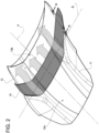
Figure 2 is a perspective view, on an enlarged scale, of the hood of the motor vehicle inFigure 1 ; -
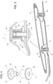
Figure 3 is a cross-section of the hood according to a plane indicated inFigure 2 by a cross-section line III-III; and -
Figure 4 is an exploded view of a device for fixing a covering panel to a framework base of the hood. - In
Figure 1 , the reference number 1 is used to indicate, as a whole, a motor vehicle. - The motor vehicle 1 has a
front part 2 and arear part 3, according to its moving direction, represented inFigure 2 via a straight longitudinal axis A. - In addition, the motor vehicle 1 comprises a
body 5 and ahood 7, in particular a front hood at thefront part 2. Thehood 7 is mounted on thebody 5. - The
hood 7 covers or closes an engine compartment that is not illustrated, which houses a known engine that is also not illustrated. - Alternatively, the
hood 7 could also have been a rear hood and/or hood covering the trunk. - The
hood 7 comprises a framework base or skeleton 8 (Figure 3 ), which has a length extension along the axis A and a width extension along an axis B orthogonal to the axis A. The axes A and B belong to a plane, horizontal in use. Therefore, in use, the axes A and B are horizontal. As already mentioned above, the axis A coincides with the moving direction of the motor vehicle 1. - The
framework base 8 has twoopposite ends end 9 is the end more at the front, i.e., it belongs to a front end of the motor vehicle 1. - In addition, the
hood 7 comprises twocovering panels framework base 8 so as to cover, respectively, theends framework base 8. - In more detail, the
covering panels - The
covering panels outer surfaces hood 7. Theouter surfaces framework base 8. In other words, theouter surfaces - In particular, the
covering panels - The
covering panels intermediate portion 14 of theframework base 8 uncovered; theintermediate portion 14 is arranged between theends - In particular, the
intermediate portion 14 is left uncovered by thecovering panels framework base 8. - This does not mean that the
intermediate portion 14 is not covered in part or entirely using other elements, devices, structures, panels, or the like, but simply that thepanels intermediate portion 14. - In fact, the
hood 7 comprises acovering panel 15 fixed to theframework base 8 so as to at least partially cover theintermediate portion 14. In more detail, the coveringpanel 15 covers only part of theintermediate portion 14. - Here and below, the expression "to cover" is intended as a synonym for "to coat". In the use context of the motor vehicle 1, covering may be understood to mean positioned above. The expression "use context" of the motor vehicle 1 is here and below used to identify a condition wherein the
hood 7 is mounted on thebody 5. - The covering
panel 15 has a wing shape. - The
covering panel 15 preferably comprises or is made of carbon fibre. The coveringpanel 15 has, for the most part, the mere function of covering; in particular, notwithstanding the wing shape, thecovering panel 15 is not suitable for generating downforce. - To fix the covering
panel 15 to theframework base 8, thehood 7 comprises afixing device 20 that will be described in detail below. - The
fixing device 20 comprises abase element 21, which is carried by the coveringpanel 15 in a fixed position relative to the latter. - In more detail, the
base element 21 is integrated with thecovering panel 15. In detail, thebase element 21 is embedded in the carbon fibre or glued to thecovering panel 15. - The
fixing device 20 also comprises aregister element 22 coupled to thebase element 21 in a movable manner relative to thebase element 21 along an axis Z transversal and, more precisely, orthogonal, to a plane comprising the axes A, B. - In the use context of the motor vehicle 1, the axis Z is vertical. In addition, the covering
panel 15 is arranged above theframework base 8. - More precisely, the
register element 22 has two degrees of freedom of movement in relation to thebase element 21 to which it is attached. A first degree of freedom is that already mentioned, i.e., a degree of freedom of translation along the axis Z. A second degree of freedom is a degree of freedom of rotation around the axis Z. Theregister element 22 does not have other degrees of freedom of movement relative to thebase element 21. - In other words, the
register element 22 is fixed to thebase element 21 according to directions that are radial to the axis Z. - In the embodiment in
Figures 3 and 4 , thebase element 21 comprises abase portion 23, in particular comprising a disc, and a pin orrod 24 extending along the axis Z from thebase portion 23. - The disc of the
base portion 23 is, specifically, glued to thecovering panel 15. - The
pin 24 comprises an externally threaded portion orexternal threading 25, which has, in particular, a diameter that is greater than the rest of thepin 24. More specifically, theexternal threading 25 corresponds to an intermediate portion of thepin 24. - Specifically, the
pin 24 projects directly from the disc of thebase portion 23, even if this is not necessary. - The
register element 22 extends along the axis Z between two ends 26, 27 respectively closer to and further from thebase portion 23, according to the axis Z. - The
end 27 faces towards theframework base 8 and is designed to abut against theframework base 8 along thethird axis 8. - In more detail, the
end 27 comprises a flat wall, in particular a cylindrical one, around the axis Z. - The
register element 22 preferably comprises, in addition, asleeve 28 arranged along or around the axis Z, i.e., coaxial to thepin 24. - The
sleeve 28 is arranged around thepin 24; in other words, thepin 24 is radially internal to thesleeve 28. - In particular, the
sleeve 28 comprises theend 26. More specifically, theregister element 22 consists of thesleeve 28 and theend 27. - In detail, the
end 27 radially projects relative to thesleeve 28. In other, more detailed words, the flat wall has a diameter that is greater than the outside diameter of thesleeve 28. - The
sleeve 28 comprises an internally threaded portion orinternal threading 29, which is coupled to theexternal threading 25. - Thus, the
register element 22 is mobile in relation to thebase element 21 for screwing or unscrewing thesleeve 28 in relation to thepin 24, i.e., of theexternal threading 25 in relation to theinternal threading 29. - Thus, the
sleeve 28 rotates around the axis Z and, at the same time, translates along the axis Z, according to the screw-nut principle. - Although this is advantageous, some variants may, in any case, be considered; for example, the
sleeve 28 could be coupled to thepin 24 so as to slide along the axis Z with an elastic member coupled to thesleeve 28 and to thebase element 21 between them. - The
end 27 preferably comprises apolygonal hole 30, more precisely a polygonal through hole, which extends along the axis Z and is, therefore, coaxial, in detail, to thesleeve 28 or to thepin 24. - The
hole 30 passes, in particular, through the flat wall of theend 27 and is positioned, in more detail, at the centre of the flat wall. - In detail, the
hole 30 has a radial extension that is smaller than an internal diameter of thesleeve 28. Independently, the radial extension of thehole 30 is greater than an external diameter of thepin 24. - The
hole 30, precisely, is hexagonal. - The
hole 30 is shaped to insert a wrench (not illustrated) designed to allow the screwing or unscrewing of thesleeve 28 in relation to thepin 24. The wrench is an Allen wrench in this case. - Thus, an operator can move the
register element 22 along the axis Z by using the wrench. - The movement along the axis Z of the
register element 22 is limited on one side by thebase portion 23, with which theend 26 may enter into contact and, on the other, by theframework base 8 or, more precisely, by aface 8a thereof, against which theend 27 abuts. - The
face 8a faces towards theregister element 22 or towards the coveringpanel 15. Theframework base 8 also has aface 8b opposite theface 8a. - The
framework base 8 has a throughhole 40 along or around the axis Z, more precisely between thefaces sleeve 28 through theframework base 8. - The
hole 40 may be considered part of the fixingdevice 20. - In the embodiment in
Figure 3 , thepin 24 has a threadedhole 33 around or along the axis Z. Thus, thehole 33 is coaxial to any of the following: thesleeve 28, thepin 24, thehole 30, theother hole 40, or the flat wall of theend 27. In particular, thehole 33 is a blind hole. - The fixing
device 20 also comprises ascrew 34 that crosses thehole 40 and is screwed into thehole 33, in this case in a piercing manner. Thescrew 34 extends along the axis Z. - The
screw 34 has ahead 35 and a threadedshank 36 that extends from thehead 35 along the axis Z. - The threaded
shank 36 passes through thehole 40, in detail with radial clearance. In this way, by radially moving thescrew 34 inside thehole 40, the position of the coveringpanel 15 can be adjusted according to the axes A, B. - The position of the covering
panel 15, according to the axis Z, may be adjusted by moving theregister element 22. - The
head 35 is tightened to the outside of thehole 40 on theface 8b and, thus, on theframework base 8. The expression "tightened" includes both the meaning of directly tightened and the meaning of indirectly tightened, for example since one or more washers may be provided between thehead 35 and theframework base 8. - The position of the covering
panel 15 is implemented as soon as thehead 35 is tightened on theface 8b, or on theframework base 8. - As can be seen in
Figure 3 , thehood 7 may comprise more than onefixing device 20; in this case, thehood 7 comprises fourfixing devices 20, of which two are visible inFigure 3 . - A process for mounting the
hood 7 may be, therefore, the following. - The covering
panel 15 is positioned in a desired position relative with respect to theframework base 8. - The covering
panel 15 may be kept in the desired position, relative to theframework base 8, via special supports that can be removed (not illustrated) during the whole process. - Thus, the
register element 22 is moved along the axis Z towards theframework base 8 while the desired position is maintained. Theregister element 22 is moved until theend 27 is brought to abut against theface 8a, or against theframework base 8. - Thus, the covering
panel 15 is rested on theframework base 8 in the desired position, for which the removable supports could even be, potentially, already removed. - As already mentioned above, the movement of the
register element 22 is obtained by screwing or unscrewing thesleeve 28 to the or from thepin 24, in particular using a wrench inserted through thehole 30. - At this point, the desired position may be stabilised or fixed.
- Thus, the covering
panel 15 is fixed to theframework base 8 in the desired position. - The fixing occurs by inserting the
screw 34 along the axis Z through thehole 40 and screwing thescrew 34 on the threadedhole 33, until tightening thehead 35 to the outside of thehole 40 on theface 8b or, more generally, on theframework base 8. - The covering
panel 15 is fixed to theframework base 8 when thehead 35 is tightened to theframework base 8. - Here, the mounting process is concluded; the
hood 7 can, thus, be mounted on thebody 5 during assembly of the motor vehicle 1. - From the above, the advantages of the
hood 7 and the process according to the invention are clear. - The covering
panel 15 can be fixed to theframework base 8 in an extremely simple and convenient way for the operator, using just a few simple and effective devices. - In fact, the operator accesses the
register element 22 via thehole 40 from below thehood 7, while the latter is supported up high, for example via a straightening bench. - The operations that the operator must undertake to fix the covering
panel 15 are simple and few in number. - In addition, the adjustment and fixing of the desired position relative to the axis Z may occur in an extremely precise way, in particular thanks to the
external threading 25 and theinternal threading 29 coupled together, especially when the pitch is tightened. - The greater width of the
hole 40 in relation to theshank 36 of thescrew 34 makes it possible, in addition, to adjust the desired position according to the axes A, B, in a very simple way. - In fact, the fixing of the desired position is completely obtained, according to the three axes A, B, Z, when the
head 35 is tightened to theframework base 8. - Finally, it is clear that changes may be made to the
hood 7 according to the invention, and variations produced thereof, that, in any case, do not depart from the scope of protection defined by the claims. - For example, the number or shape of the components described and illustrated could vary, without any loss of generality.
Claims (10)
- A hood (7) for a motor vehicle (1), the hood (7) being configured to be mounted on a body (5) of the motor vehicle (1) and comprising- a framework base (8) having a length extension along a first axis (A) and a width extension along a second axis (B) orthogonal to the first axis (A),- a covering panel (15) for at least partially covering a portion (14) of the framework base (8), and- fixing means (20) for fixing the covering panel (15) to said portion (14), such that the covering panel (15) at least partially covers the portion (14),the fixing means (20) comprising a base element (21) carried by the covering panel (15) in a fixed position relative to the covering panel (15),characterized in that the fixing means (20) further comprise a register element (22) coupled to the base element (21) in a movable manner relative to the base element (22) along a third axis (Z) transversal to a plane comprising the first and the second axis (A, B),wherein the register element (22) has an end (27) that is farther from the base element (21) along the third axis (Z) and faces the framework base (8), the end (27) being adapted to abut against the framework base (8) along the third axis (Z).
- The hood according to claim 1, wherein the base element (21) comprises a base portion (23) and a pin (24) extending along the third axis (Z) of the base portion (23) and comprising an externally threaded portion (25), the register element (22) comprising a sleeve (28) arranged along the third axis (Z) between the base portion (23) and said end (27) and comprising an internally threaded portion (29) coupled to the externally threaded portion (25).
- The hood according to claim 2, wherein said end (27) comprises a polygonal hole (30) around the third axis (Z) for the insertion of a wrench adapted to screw or unscrew the internally threaded portion (29) to or from the externally threaded position (25).
- The hood according to claim 2 or 3, wherein the pin (24) has a threaded hole (33) around the third axis (Z).
- The hood according to claim 4, wherein the fixing means (20) further comprise a through hole (40) obtained on the framework base (8) around the third axis (Z) and a screw (34) going through the through hole (40) and screwed into the threaded hole (33), the screw (34) having a head (35) tightened on the outside of the through hole (40) on a first face (8a) of the framework base (8) opposite to a second face (8b) of the framework base (8), the second face (8b) facing the register element (22).
- A process for assembling a hood (7) according to any one of the preceding claims, the process comprising the steps of- placing the covering panel (15) in a relative position with respect to the framework base (8),- moving the register element (22) along the third axis (Z) towards the framework base (8) keeping said relative position until the end (27) of the register element (22) abuts against the framework base (8), thereby laying the covering panel (15) on the framework base (8), and- fixing the covering panel (15) to the framework base (8) in said relative position.
- The process according to claim 6, wherein the step of moving the register element (22) comprises the step of screwing or unscrewing an internally threaded sleeve (28) of the register element (22) to or from an externally threaded pin (24), the pin (24) being part of the base element (21) and extending along the third axis (Z) from a base portion (23) of the base element (21).
- The process according to claim 7, wherein the step of screwing or unscrewing the sleeve (28) takes place by means of a wrench inserted through a polygonal hole (30) of the end (27) of the register element (22) around the third axis (Z).
- The process according to claim 6 or 7, wherein the step of fixing the covering panel (15) comprises the steps of- inserting a wrench (34) along the third axis (Z) through a through hole (40) made in the framework base (8),- screwing the screw (34) into a threaded hole (33) made in the pin (24) along the third axis (Z),- tightening a head (35) of the screw (34) on the outside of the through hole (40) on a first face (8a) of the framework base (8) opposite to a second face (8b) of the framework base (8), the second face (8b) facing the register element (22), thereby fixing the covering panel (15) to the framework base (8).
- A motor vehicle (1) comprising a body (5) and a hood (7) according to any one of the claims from 1 to 5, the hood (7) being mounted on the body (5) with the first axis (A) coinciding with the moving direction of the motor vehicle (1) .
Applications Claiming Priority (1)
| Application Number | Priority Date | Filing Date | Title |
|---|---|---|---|
| IT202200000434 | 2022-01-13 |
Publications (1)
| Publication Number | Publication Date |
|---|---|
| EP4212412A1 true EP4212412A1 (en) | 2023-07-19 |
Family
ID=80933413
Family Applications (1)
| Application Number | Title | Priority Date | Filing Date |
|---|---|---|---|
| EP23151082.7A Pending EP4212412A1 (en) | 2022-01-13 | 2023-01-11 | Hood for a motor vehicle and process for the assembling thereof |
Country Status (4)
| Country | Link |
|---|---|
| US (1) | US12466495B2 (en) |
| EP (1) | EP4212412A1 (en) |
| JP (1) | JP2023103181A (en) |
| CN (1) | CN116424434A (en) |
Families Citing this family (1)
| Publication number | Priority date | Publication date | Assignee | Title |
|---|---|---|---|---|
| JP2023103181A (en) * | 2022-01-13 | 2023-07-26 | フェラーリ エッセ.ピー.アー. | Automobile hood and its assembly method |
Citations (1)
| Publication number | Priority date | Publication date | Assignee | Title |
|---|---|---|---|---|
| US5950753A (en) * | 1997-07-14 | 1999-09-14 | Chrysler Corporation | Vehicle hood louvers water management system |
Family Cites Families (10)
| Publication number | Priority date | Publication date | Assignee | Title |
|---|---|---|---|---|
| US3274638A (en) * | 1963-08-08 | 1966-09-27 | Chrysler Corp | Fastener arrangement |
| US4153291A (en) * | 1978-03-23 | 1979-05-08 | Conti Nicholas R | Viewport assembly |
| US4629022A (en) * | 1984-05-18 | 1986-12-16 | Choo Choo Customs, Inc. | Hoodscoop and method for attaching the same |
| US5275249A (en) * | 1991-11-27 | 1994-01-04 | Nelson Richard L | Raisable hood plate mechanism |
| US7788860B2 (en) * | 2003-07-07 | 2010-09-07 | Zartman Ronald R | Vandal proof system for securing a frangible facing plate to rigid supporting structure by wedging action and a method therefor |
| US8678483B2 (en) * | 2011-05-06 | 2014-03-25 | Kevin Quirk | Window assembly for an automobile hood |
| US8616622B2 (en) * | 2011-07-28 | 2013-12-31 | Maclean Fogg Company | Energy management hood bumper |
| US9889890B1 (en) * | 2017-01-20 | 2018-02-13 | Ford Global Technologies, Llc | Vehicle hood system |
| JP2023103180A (en) * | 2022-01-13 | 2023-07-26 | フェラーリ エッセ.ピー.アー. | automotive hood |
| JP2023103181A (en) * | 2022-01-13 | 2023-07-26 | フェラーリ エッセ.ピー.アー. | Automobile hood and its assembly method |
-
2023
- 2023-01-05 JP JP2023000529A patent/JP2023103181A/en active Pending
- 2023-01-10 CN CN202310035653.2A patent/CN116424434A/en active Pending
- 2023-01-10 US US18/152,348 patent/US12466495B2/en active Active
- 2023-01-11 EP EP23151082.7A patent/EP4212412A1/en active Pending
Patent Citations (1)
| Publication number | Priority date | Publication date | Assignee | Title |
|---|---|---|---|---|
| US5950753A (en) * | 1997-07-14 | 1999-09-14 | Chrysler Corporation | Vehicle hood louvers water management system |
Non-Patent Citations (2)
| Title |
|---|
| AUTOCAR: "Ferrari 812 Competizione review | 819bhp, 450,000 limited edition track tested | Autocar", 10 November 2021 (2021-11-10), XP055956110, Retrieved from the Internet <URL:https://www.youtube.com/watch?v=84jRolWAot4> [retrieved on 20220830] * |
| FERRARI PRESS OFFICE: "812 Competizione and 812 Competizione A: two interpretations of Ferrari's racing soul", 5 May 2021 (2021-05-05), pages 1 - 9, XP055956137, Retrieved from the Internet <URL:https://www.ferrari.com/en-EN/corporate/articles/812-competizione-and-812-competizione-a-two-interpretations-of-ferraris-racing-soul> [retrieved on 20220830] * |
Also Published As
| Publication number | Publication date |
|---|---|
| US20230219632A1 (en) | 2023-07-13 |
| JP2023103181A (en) | 2023-07-26 |
| CN116424434A (en) | 2023-07-14 |
| US12466495B2 (en) | 2025-11-11 |
Similar Documents
| Publication | Publication Date | Title |
|---|---|---|
| US5492388A (en) | Structure for steering member | |
| US9032834B2 (en) | Steering device | |
| US5074609A (en) | Adjustable deck lid hinge pivot | |
| EP4212412A1 (en) | Hood for a motor vehicle and process for the assembling thereof | |
| US20130111703A1 (en) | Adjustable pivot deck lid | |
| PT2188155E (en) | Device for fastening plastic parts to a motor vehicle body | |
| CN105745144B (en) | The adjustable component of activity car body panel and fixed car body panel | |
| JPS59185998A (en) | Bow for archery | |
| EP4257832B1 (en) | Alignment element for positioning an attachment part | |
| DE10002956A1 (en) | Headlight assembly for a motor vehicle | |
| US10836473B2 (en) | Mechanisms, systems and methods to allow step-ajdustment of aerodynamic surfaces | |
| US4381884A (en) | Adjustable holder for an optical element | |
| CN101379265A (en) | Hinge for doors, windows or the like | |
| US11326377B2 (en) | Hood prop | |
| US7055647B2 (en) | Electrically-assisted steering mechanism for vehicles | |
| CN224169701U (en) | Adjusting device and profile frame for fairing closing | |
| US6973749B2 (en) | Equipment for testing a small-calibre weapon on a test bench | |
| JP4713744B2 (en) | Electronic device attachment arm device | |
| CN216994601U (en) | An automobile saddle adjustment rod | |
| CN103687742A (en) | Simply articulated fuel flap and method of fitting the fuel flap to a vehicle | |
| CN222336750U (en) | Clamping tool for steering wheel fatigue test | |
| JP2002068038A (en) | Door mounting method for automobiles | |
| EP4212415B1 (en) | Hood assembly for a motor vehicle and process for the mounting thereof | |
| JPS6036688Y2 (en) | Automotive door hinge positioning device | |
| JPH0469117A (en) | Panel positioning method |
Legal Events
| Date | Code | Title | Description |
|---|---|---|---|
| PUAI | Public reference made under article 153(3) epc to a published international application that has entered the european phase |
Free format text: ORIGINAL CODE: 0009012 |
|
| STAA | Information on the status of an ep patent application or granted ep patent |
Free format text: STATUS: THE APPLICATION HAS BEEN PUBLISHED |
|
| AK | Designated contracting states |
Kind code of ref document: A1 Designated state(s): AL AT BE BG CH CY CZ DE DK EE ES FI FR GB GR HR HU IE IS IT LI LT LU LV MC ME MK MT NL NO PL PT RO RS SE SI SK SM TR |
|
| STAA | Information on the status of an ep patent application or granted ep patent |
Free format text: STATUS: REQUEST FOR EXAMINATION WAS MADE |
|
| 17P | Request for examination filed |
Effective date: 20240109 |
|
| RBV | Designated contracting states (corrected) |
Designated state(s): AL AT BE BG CH CY CZ DE DK EE ES FI FR GB GR HR HU IE IS IT LI LT LU LV MC ME MK MT NL NO PL PT RO RS SE SI SK SM TR |
|
| STAA | Information on the status of an ep patent application or granted ep patent |
Free format text: STATUS: EXAMINATION IS IN PROGRESS |
|
| 17Q | First examination report despatched |
Effective date: 20260112 |