EP4212388A1 - A child safety seat rotatably mounted on a base - Google Patents
A child safety seat rotatably mounted on a base Download PDFInfo
- Publication number
- EP4212388A1 EP4212388A1 EP23150380.6A EP23150380A EP4212388A1 EP 4212388 A1 EP4212388 A1 EP 4212388A1 EP 23150380 A EP23150380 A EP 23150380A EP 4212388 A1 EP4212388 A1 EP 4212388A1
- Authority
- EP
- European Patent Office
- Prior art keywords
- seat
- base
- latch
- child safety
- rotary element
- Prior art date
- Legal status (The legal status is an assumption and is not a legal conclusion. Google has not performed a legal analysis and makes no representation as to the accuracy of the status listed.)
- Granted
Links
Images







Classifications
-
- B—PERFORMING OPERATIONS; TRANSPORTING
- B60—VEHICLES IN GENERAL
- B60N—SEATS SPECIALLY ADAPTED FOR VEHICLES; VEHICLE PASSENGER ACCOMMODATION NOT OTHERWISE PROVIDED FOR
- B60N2/00—Seats specially adapted for vehicles; Arrangement or mounting of seats in vehicles
- B60N2/24—Seats specially adapted for vehicles; Arrangement or mounting of seats in vehicles for particular purposes or particular vehicles
- B60N2/26—Seats specially adapted for vehicles; Arrangement or mounting of seats in vehicles for particular purposes or particular vehicles for children
- B60N2/28—Seats readily mountable on, and dismountable from, existing seats or other parts of the vehicle
- B60N2/2869—Seats readily mountable on, and dismountable from, existing seats or other parts of the vehicle rotatable about a vertical axis
-
- B—PERFORMING OPERATIONS; TRANSPORTING
- B60—VEHICLES IN GENERAL
- B60N—SEATS SPECIALLY ADAPTED FOR VEHICLES; VEHICLE PASSENGER ACCOMMODATION NOT OTHERWISE PROVIDED FOR
- B60N2/00—Seats specially adapted for vehicles; Arrangement or mounting of seats in vehicles
- B60N2/02—Seats specially adapted for vehicles; Arrangement or mounting of seats in vehicles the seat or part thereof being movable, e.g. adjustable
- B60N2/04—Seats specially adapted for vehicles; Arrangement or mounting of seats in vehicles the seat or part thereof being movable, e.g. adjustable the whole seat being movable
- B60N2/14—Seats specially adapted for vehicles; Arrangement or mounting of seats in vehicles the seat or part thereof being movable, e.g. adjustable the whole seat being movable rotatable, e.g. to permit easy access
- B60N2/146—Seats specially adapted for vehicles; Arrangement or mounting of seats in vehicles the seat or part thereof being movable, e.g. adjustable the whole seat being movable rotatable, e.g. to permit easy access characterised by the locking device
-
- B—PERFORMING OPERATIONS; TRANSPORTING
- B60—VEHICLES IN GENERAL
- B60N—SEATS SPECIALLY ADAPTED FOR VEHICLES; VEHICLE PASSENGER ACCOMMODATION NOT OTHERWISE PROVIDED FOR
- B60N2/00—Seats specially adapted for vehicles; Arrangement or mounting of seats in vehicles
- B60N2/24—Seats specially adapted for vehicles; Arrangement or mounting of seats in vehicles for particular purposes or particular vehicles
- B60N2/26—Seats specially adapted for vehicles; Arrangement or mounting of seats in vehicles for particular purposes or particular vehicles for children
-
- B—PERFORMING OPERATIONS; TRANSPORTING
- B60—VEHICLES IN GENERAL
- B60N—SEATS SPECIALLY ADAPTED FOR VEHICLES; VEHICLE PASSENGER ACCOMMODATION NOT OTHERWISE PROVIDED FOR
- B60N2/00—Seats specially adapted for vehicles; Arrangement or mounting of seats in vehicles
- B60N2/24—Seats specially adapted for vehicles; Arrangement or mounting of seats in vehicles for particular purposes or particular vehicles
- B60N2/26—Seats specially adapted for vehicles; Arrangement or mounting of seats in vehicles for particular purposes or particular vehicles for children
- B60N2/28—Seats readily mountable on, and dismountable from, existing seats or other parts of the vehicle
- B60N2/2821—Seats readily mountable on, and dismountable from, existing seats or other parts of the vehicle having a seat and a base part
-
- B—PERFORMING OPERATIONS; TRANSPORTING
- B60—VEHICLES IN GENERAL
- B60N—SEATS SPECIALLY ADAPTED FOR VEHICLES; VEHICLE PASSENGER ACCOMMODATION NOT OTHERWISE PROVIDED FOR
- B60N2/00—Seats specially adapted for vehicles; Arrangement or mounting of seats in vehicles
- B60N2/24—Seats specially adapted for vehicles; Arrangement or mounting of seats in vehicles for particular purposes or particular vehicles
- B60N2/26—Seats specially adapted for vehicles; Arrangement or mounting of seats in vehicles for particular purposes or particular vehicles for children
- B60N2/28—Seats readily mountable on, and dismountable from, existing seats or other parts of the vehicle
- B60N2/2821—Seats readily mountable on, and dismountable from, existing seats or other parts of the vehicle having a seat and a base part
- B60N2/2824—Seats readily mountable on, and dismountable from, existing seats or other parts of the vehicle having a seat and a base part part of the base being supported by the vehicle frame
-
- B—PERFORMING OPERATIONS; TRANSPORTING
- B60—VEHICLES IN GENERAL
- B60N—SEATS SPECIALLY ADAPTED FOR VEHICLES; VEHICLE PASSENGER ACCOMMODATION NOT OTHERWISE PROVIDED FOR
- B60N2/00—Seats specially adapted for vehicles; Arrangement or mounting of seats in vehicles
- B60N2/24—Seats specially adapted for vehicles; Arrangement or mounting of seats in vehicles for particular purposes or particular vehicles
- B60N2/26—Seats specially adapted for vehicles; Arrangement or mounting of seats in vehicles for particular purposes or particular vehicles for children
- B60N2/28—Seats readily mountable on, and dismountable from, existing seats or other parts of the vehicle
- B60N2/2821—Seats readily mountable on, and dismountable from, existing seats or other parts of the vehicle having a seat and a base part
- B60N2/2827—Seats readily mountable on, and dismountable from, existing seats or other parts of the vehicle having a seat and a base part part of the base being supported by the seat sub-frame
-
- B—PERFORMING OPERATIONS; TRANSPORTING
- B60—VEHICLES IN GENERAL
- B60N—SEATS SPECIALLY ADAPTED FOR VEHICLES; VEHICLE PASSENGER ACCOMMODATION NOT OTHERWISE PROVIDED FOR
- B60N2/00—Seats specially adapted for vehicles; Arrangement or mounting of seats in vehicles
- B60N2/24—Seats specially adapted for vehicles; Arrangement or mounting of seats in vehicles for particular purposes or particular vehicles
- B60N2/26—Seats specially adapted for vehicles; Arrangement or mounting of seats in vehicles for particular purposes or particular vehicles for children
- B60N2/28—Seats readily mountable on, and dismountable from, existing seats or other parts of the vehicle
- B60N2/2842—Seats readily mountable on, and dismountable from, existing seats or other parts of the vehicle adapted to carry the child, when dismounted from the vehicle
- B60N2/2845—Seats readily mountable on, and dismountable from, existing seats or other parts of the vehicle adapted to carry the child, when dismounted from the vehicle having handles
-
- B—PERFORMING OPERATIONS; TRANSPORTING
- B60—VEHICLES IN GENERAL
- B60N—SEATS SPECIALLY ADAPTED FOR VEHICLES; VEHICLE PASSENGER ACCOMMODATION NOT OTHERWISE PROVIDED FOR
- B60N2/00—Seats specially adapted for vehicles; Arrangement or mounting of seats in vehicles
- B60N2/24—Seats specially adapted for vehicles; Arrangement or mounting of seats in vehicles for particular purposes or particular vehicles
- B60N2/26—Seats specially adapted for vehicles; Arrangement or mounting of seats in vehicles for particular purposes or particular vehicles for children
- B60N2/28—Seats readily mountable on, and dismountable from, existing seats or other parts of the vehicle
- B60N2/2857—Seats readily mountable on, and dismountable from, existing seats or other parts of the vehicle characterised by the peculiar orientation of the child
-
- B—PERFORMING OPERATIONS; TRANSPORTING
- B60—VEHICLES IN GENERAL
- B60N—SEATS SPECIALLY ADAPTED FOR VEHICLES; VEHICLE PASSENGER ACCOMMODATION NOT OTHERWISE PROVIDED FOR
- B60N2/00—Seats specially adapted for vehicles; Arrangement or mounting of seats in vehicles
- B60N2/24—Seats specially adapted for vehicles; Arrangement or mounting of seats in vehicles for particular purposes or particular vehicles
- B60N2/26—Seats specially adapted for vehicles; Arrangement or mounting of seats in vehicles for particular purposes or particular vehicles for children
- B60N2/28—Seats readily mountable on, and dismountable from, existing seats or other parts of the vehicle
- B60N2/2887—Fixation to a transversal anchorage bar, e.g. isofix
- B60N2/2893—Fixation to a transversal anchorage bar, e.g. isofix coupled to the seat sub-frame
-
- B—PERFORMING OPERATIONS; TRANSPORTING
- B60—VEHICLES IN GENERAL
- B60N—SEATS SPECIALLY ADAPTED FOR VEHICLES; VEHICLE PASSENGER ACCOMMODATION NOT OTHERWISE PROVIDED FOR
- B60N2/00—Seats specially adapted for vehicles; Arrangement or mounting of seats in vehicles
- B60N2/02—Seats specially adapted for vehicles; Arrangement or mounting of seats in vehicles the seat or part thereof being movable, e.g. adjustable
- B60N2002/0204—Seats specially adapted for vehicles; Arrangement or mounting of seats in vehicles the seat or part thereof being movable, e.g. adjustable characterised by the seat or seat part turning about or moving along a non-standard, particular axis, i.e. an axis different from the axis characterising the conventional movement
- B60N2002/022—Seats specially adapted for vehicles; Arrangement or mounting of seats in vehicles the seat or part thereof being movable, e.g. adjustable characterised by the seat or seat part turning about or moving along a non-standard, particular axis, i.e. an axis different from the axis characterising the conventional movement the seat or seat part turning about or moving along a vertical axis
-
- B—PERFORMING OPERATIONS; TRANSPORTING
- B60—VEHICLES IN GENERAL
- B60N—SEATS SPECIALLY ADAPTED FOR VEHICLES; VEHICLE PASSENGER ACCOMMODATION NOT OTHERWISE PROVIDED FOR
- B60N2/00—Seats specially adapted for vehicles; Arrangement or mounting of seats in vehicles
- B60N2/90—Details or parts not otherwise provided for
- B60N2/919—Positioning and locking mechanisms
- B60N2002/952—Positioning and locking mechanisms characterised by details of the locking system
Definitions
- the invention relates to a child safety seat mounted to a base where the child safety seat can rotate with respect to the base.
- the child safety seat and base can be secured to a motor vehicle's seat for the carriage of a child in the vehicle.
- a means of controlling the rotation of the seat with respect to the base as well as a means of removing and locking the child safety seat to the base are disclosed.
- Examples of child safety seats that can be rotated with respect to a base are known. With some examples where the base is secured to a motor vehicle's seat, the child safety seat can be rotated with respect to the base to move the seat between in-use positions in either a forward or rear facing position. This allows the seat to be at a side loading position, 90 degrees with respect to either in-use position, to allow easy seating or extraction of a child from a doorway of a motor vehicle.
- a child safety seat it is useful to allow a child safety seat to be released from the base to, for example, attach the seat to a stroller.
- This can be achieved with a base that has a rotary element mounted for rotary movement in the base.
- the rotary element has latches on its upper surface to which the child safety seat affixes and the child safety seat has latching elements that engage with the rotary element latches.
- the latches securely hold the seat and are sufficiently strong to withstand loads applied during vehicle impact conditions.
- a means of securing a separable child seat to the rotary element of the base in the correct position is desirable and any system that does not ensure the correct orientation may lead to unsafe outcomes.
- the rotary element may be configured to latch with respect to the base so as to position the child safety seat in one or more in-use positions. These include a rear facing and a forward facing position. Manual means may be provided to release the latch between the base and the rotary element to allow rotation of the child safety seat with respect to the base.
- the rotary element is arranged to rotate so that the child safety seat may be repositioned with respect to the base and vehicle seat to move the child safety seat to a position where it is easier or more convenient to position a child into the safety seat or to remove the child. This may include rotating the seat so that it is aligned with an open vehicle door.
- the latch may include a plurality of hooks mounted to the rotary element that move between a latching position and an unlatched position.
- the child safety seat may have latch engaging elements such as pins or similar elements over which the hooks may engage.
- the hooks may comprise a simple right-angled hook that works in conjunction with a vertical abutment or notch on the rotary element. Both act to prevent movement of the latch engaging elements once the hook is over it. The hook will prevent upward movement and horizontal movement towards the hook and the vertical abutment will prevent horizontal movement in the opposite direction.
- the child safety seat is rotated from an in-use position to a second predetermined position where operation of the latch will also allow actuation of the interlock means which will act to hold the rotary element at that predetermined position. Operation of the interlock means prevents the rotary element from moving away from the pre-determined position once the child safety seat is removed.
- the interlock means may prevent operation of the latch to release the lock means once the child safety seat is removed from the rotary base. In this way, the rotary base is prevented from moving from the position where the child safety seat is removed from the base and the rotary element cannot be moved from this position while the child safety seat is removed.
- the interlock means is released once the child safety seat is positioned onto the rotary element with its latch engagement elements aligned with the latch.
- One or more of the latch elements may depress spring loaded actuating elements that then enables the rotary element to rotate with respect to the base once the child safety seat is in position to be re-latched to the rotary element.
- the latch may be designed to be disabled or non-operable when the child safety seat is in an in-use position. That is, the operation of the latch to release the child safety seat is not possible when it is in position for carriage of a child while the vehicle is moving. This prevents inadvertent release of the child safety seat when it is in one of its in-use positions.
- a child safety seat and base assembly wherein a base is arranged to be secured with respect to a motor vehicle and a seat is arranged to be removably secured with respect to the base, the assembly including:
- the seat latch actuation assembly includes a handle slidably mounted with respect to the rotary element.
- the base blocks access to the handle when the seat is in any position other than one or two side-loading position(s), thereby preventing opening or closing the seat latch when the seat is in any position other than the one or two side-loading position(s).
- the child safety seat and a base further includes a plurality of hooks and hook-engageable projections, the hooks movable from a latching position in which they hold the hook-engageable projections, to a released position in which they do not hold the projections.
- the hooks are located on the rotary element and form part of the seat latch and the hook-engageable projections are located on the seat.
- the interlock mechanism includes a locking projection and a locking recess, the locking projection engageable with the locking recess to prevent rotation of the rotary element with respect to the base when the seat latch is opened.
- the locking projection extends from the rotary element and the locking recess is formed in the base.
- the rotary element includes a depressible element engageable by a seat-depending surface, whereby the depressible element is depressible by the seat-depending surface to release the interlock mechanism.
- the depressible element includes an interlock pin, the interlock pin biased toward an upper position in which the interlock mechanism locks, thereby preventing rotation of the rotary element with respect to the base.
- the interlock mechanism includes an interlock latch, the interlock latch actuated by the interlock pin.
- the interlock latch is biased towards an upper position in which an end face of the interlock latch blocks movement of the handle, thereby preventing deactivation of the interlock mechanism until the interlock pin is depressed.
- the interlock latch is pivotally mounted to the rotary element.
- a child safety seat and base 10 comprises a child seat 11 secured to the base 12.
- the base 12 is designed to locate on and secure to the seat portion of a motor vehicle seat and optionally has a rebound bar 13 that abuts against the backrest of the vehicle seat and, again optionally, a foot prop 14 (partially shown in Figures 1 and 2 ) to restrain rear and forward rotation respectively of the child seat 11 and base 12.
- Isofix connectors (not drawn) connect and secure the base 12 with respect to the vehicle seat.
- the child safety seat and base 10 may be arranged and constructed for belted installation using a motor vehicle's seat belts and a top tether or a foot prop for example.
- the child safety seat and base 10 may be arranged and constructed for installation by means of a latch system commonly used in the United States.
- the child seat 11 is in a rear facing in-use position. That is, the child will be facing the rear of the vehicle which is a position recommended for infants, babies and very young children.
- the child seat 11 With the base 12 remaining in a fixed position with respect to a vehicle seat, the child seat 11 is able to rotate through 360 degrees. As seen in Figure 4A , the child seat 11 is secured to a rotary element 18 and together, the child seat 11 and rotary element 18 are able to rotate about a substantially vertical axis on the base 12.
- a seat latch acts with the rotary element 18 and the base 12 to hold the child seat 11 in one of two in-use positions, either rear facing as shown in Figures 1 to 3 or forward facing.
- the seat latch may be manually operated, using a handle 31, and once released, the child seat 11 can be rotated to the opposite in-use position or to pre-determined intermediate positions.
- the intermediate positions are preferably 90 degrees from the in-use positions in either a clockwise or anticlockwise direction. This will have the advantage of positioning the child seat 11 towards the open door of a motor vehicle.
- the rotary element 18 is provided with a seat latch which includes a seat latch body 20 as seen in Figures 4A and 4B .
- the seat latch body 20 slides within the rotary element 18 as will be described in detail below.
- the seat latch body 20 is manually operated between a latched and unlatched position.
- the rotary element 18 comprises a generally circular disc that locates into a complimentary shaped cavity 21 in the base 12.
- the cavity 21 has a floor 24.
- the rotary element 18 has a peripheral flange 22 that sits on a bearing surface 23 on the base 12, as is shown in Figure 5 , and the rotary element 18 is held captive in the cavity 21 by a retainer 25 that has threaded fasteners 26 that secure it to the base 12.
- the rotary element 18 has a cavity 28 within which the latch body 20 locates. Positioned around the cavity 28 is a U-shaped rim 29 located on the upper surface 19 of the rotary element 18.
- the rim 29 has a number of notches 30 spaced around its periphery.
- the seat latch body 20 has an upturned handle 31 at the end of a plate 32 that extends from the seat latch body 20. Hooks 35 are located on the upper surface of both the plate 32 and the latch body 20. Lugs 36 extend laterally from the seat latch body 20 at the lower edge of the seat latch body 20. A locking projection in the form of a pin 37, shown in Figures 4 and 6 , extends from an end of the seat latch body 20.
- the seat latch body 20 is located within the cavity 28 by inserting the handle 31 through the cavity 28 from the underside of the rotary element 18.
- the lugs 36 locate in cavities 39 on the underside surface of the rotary element 18 as is shown in Figure 6 .
- the cavities 39 allow back and forth movement of the lugs 36 as the seat latch body 20 is moved between its latched and unlatched positions of Figures 4A and 4B respectively.
- the combination of the pin 37 and the lugs 36 slidably retain the latch body 20 in the cavity 28 of the rotary element 18.
- the under surface of the seat 11 has a box 40 having a generally rectangular peripheral wall which is sized to locate over the rim 29.
- Hook-engageable projections in the form of pins 41 are located on the inner wall of the box 40 and align with the notches 30 of the rim 29.
- the seat is held to the rotary element 18 with the hooks 35 positioned over the pins 41.
- Figure 7 shows the child seat 11 rotated 90 degrees from the position shown in Figures 1 to 3 .
- a manual latch (not shown) is actuated to allow the child seat 11 to move from its in-use position.
- the retainer 25 has a flange 43 that extends around the retainer 25.
- the flange 43 has two openings 44 positioned 90 degrees from the in-use positions. The flange 43 prevents access to the handle 31 in all but the 90 degree positions. However, the openings 44 allow access to the handle 31 when the child seat 11 is rotated to this pre-determined position.
- base 12 can be arranged to prevent the latch body 20 moving back to a closed position and to prevent the rotary element rotating while the seat 11 is removed.
- An interlock which comprises spring loaded actuating pins 45 and spring loaded interlock latches in the form of latch bars 46.
- the latch bars 46 are mounted in slots 48 in the floor 24 of the cavity 21.
- the latch bars 46 have pivot pins 49 that engage apertures in the slots 48. This allows upward pivoting movement of the latch bars 46 within the slots 48.
- the latch bars 46 are biased upwardly by springs 50 that are held in place below the latch bars 46 by a base plate 51.
- the springs 50 may have pivot pins that also engage pivot holes in the slots 48 and have hooks at their ends that engage retaining holes in both the latch bar 46 and the base 51.
- the latch bars 46 are held in the floor 24 of the cavity 21 with the base of the rotary element 18 moving over them as it rotates.
- the actuating pins 45 are mounted in the rotary element and move with it as it is rotated. As seen in Figure 8 , with the seat 11 removed the actuating pins 45 are urged upwardly by springs 52. As seen in Figures 9 and 10 , the actuating pins 45 with springs 52 are mounted in a bore 53. The actuating pins have collars 54 against which the springs 52 act to push the actuating pin 45 upwardly into the position shown in Figures 8 to 10 .
- the latch body 20 can be moved to the unlatch position where the seat 11 can be removed. This is the position shown in Figures 9 and 10 .
- slots 56 in the base of the rotary element 18 align with the latch bars 46.
- the upward biasing of the springs 50 results in the latch bars 46 pivoting upwardly so that their ends locate into the slots 56 shown on Figure 6 .
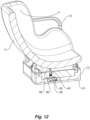
- the box 40 Upon replacing the seat 11 onto the base, the box 40 has interlock pins 58, visible in Figure 12 , that, as the pins 41 locate into the notches 30, press against the top of the actuating pins 45 and press them downwardly. This is against the biasing of springs 52.
- the lower ends of the actuating pins 45 press the respective latch bars 46 down so that, as seen in Figure 12 , the top surface of the latch bars 46 are level with the base of the rotary element 18. This also results in the end of the latch bar 46 being clear of the slots 56.
- the latch body 20 can be moved to the latched position with the hooks 35 again locating over the pins 41. With the latch bars 46 in their lower position, the lugs 36 are now able to move over the latch bars 46 as seen in Figure 12 .
- interlock pins 58 are described separately from hook-engageable pins 41, in some example the same extended pin will serve the function of both interlock pins 58 and hook-engageable pins 41.
- FIG. 18 an alternative child safety seat and base combination is shown.
- the seat 11 and its box 40 are the same, or largely the same as those shown in Figure 6 .
- the rotary element 18 and the seat latch are different.
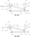
- two pairs of hooks 35 face each other as is shown more clearly in Figures 20A and 20B .
- This provides a reduced vulnerability against acceleration or deceleration as compared to an arrangement of hooks 35 that all face in the same direction as shown in Figures 1 to 17 .
- the arrangement shown in Figures 20A and 20B therefore may provide better resistance to unwanted release in the event of a frontal or rearward impact in a motor vehicle accident.
- Figures 18 and 19 show a child safety seat 11 and base 12 assembly wherein a base 11 is arranged to be secured with respect to a motor vehicle and a seat is arranged to be removably secured with respect to the base.
- the assembly includes a rotary element 18, rotatably mounted to the base (most clearly shown in Figure 19 ).
- the child seat 11 is securable to the rotary element 18 and together, the child seat 11 and rotary element 18 are able to rotate about a substantially vertical axis on the base 12.
- a pivot bearing support 70 on the base 12 is shown in Figure 18 .
- a corresponding attachment feature (not shown) is provided on the underside of the rotary element 18 thereby providing the substantially vertical axis.
- a seat latch is provided on the rotary element that engages the child safety seat to releasably hold the child safety seat with respect to the base and rotary element.
- the seat latch includes a plurality of hooks 35 and hook-engageable projections 41 as shown in Figure 24 .
- the hook-engageable projections are in the form of hook engageable pins 41.
- the hooks 35 are movable from a latching position in which they hold the hook-engageable projections, as shown in Figures 20A and 21A , to a released position in which they do not hold the projections, as shown in Figures 20B and 21B .
- Figures 20A and 20B on the one hand, and Figures 21A and 21B on the other hand, show alternative arrangements.
- a pull-release mechanism within the rotary element is provided.
- a push-release mechanism within the rotary element is provided.
- the base 12 blocks access to the handle 31 when the seat 11 is in any position other than one or two side-loading position, thereby preventing opening or closing the seat latch when the seat is in any position other than side-loading position(s).
- the base 12 blocks access to the handle 31 when the seat 11 is in any position other than one or two side-loading position, thereby preventing opening or closing the seat latch when the seat is in any position other than side-loading position(s).
- the base 12 blocks access to the handle 31 when the seat 11 is in any position other than one or two side-loading position, thereby preventing opening or closing the seat latch when the seat is in any position other than side-loading position(s).
- the assembly further includes a seat latch actuation assembly for opening or closing the seat latch wherein opening the seat latch releases the child safety seat.
- the seat latch actuation assembly includes a handle 31 slidably mounted with respect to the rotary element.
- the interlock mechanism prevents rotation of the rotary element 18 with respect to the base 12.
- the interlock mechanism includes a locking projection, in the form of a pin 37 and a locking recess, in the form of an aperture 38.
- the pin 37 is engageable with the aperture 38 to prevent rotation of the rotary element 18 with respect to the base 12 when the seat latch is opened.
- the pin 37 extends from the rotary element 18 when the hooks 35 are open as can be seen in Figures 20B , 25B , 21B and 26B .
- the aperture 38 is formed in the base 12 as is shown in Figure 18 .
- the rotary element 18 includes a depressable element in the form of an actuating pin 45 as shown in Figures 18 and 19 .
- Multiple actuating pins 45 may be provided as is more clearly shown in the first example as is illustrated in Figure 8 for instance.
- the pins 45 are engageable by a seat-depending surface in the form of an interlock pin 58, or pins 58, as are shown in Figure 22 .
- the depressible pins 45 are depressible by the pins 58 on the seat to release the interlock mechanism.
- the depressible interlock pin or pins 45 are biased toward an upper position in which the interlock mechanism locks, thereby preventing rotation of the rotary element 18 with respect to the base 12.
- the interlock mechanism includes an interlock latch 46, the interlock latch is actuated by the interlock pin 45 as is illustrated in Figures 9 and 10 .
- the interlock latch 46 is biased towards an upper position in which an end face 46' of the interlock latch 46 blocks movement of the handle 31, thereby preventing deactivation of the interlock mechanism until the interlock pin 45 is depressed.
- the interlock latch is pivotally mounted to the rotary element 18.
- a handle linkage 80 that is either operatively connected to the handle 31 or forms part of the handle 31, is pivotally connected to a pair hook linkages 90 at pivot points 95 and 96.
- This arrangement is the pull-release mechanism within the rotary element 18 shown in Figures 20A and 20B respectively.
- Figures 11 to 17 show the seat 11 being removed from the right hand side of the base 12.
- the latch bars 46 are on the left side of the base 12 to allow the apertures 56 to align in this position.
- a further set of latch bars 46 would need to be provided on the right side of the base 12 in order to allow removal of the seat 11 from the left side of the base 12.
- the described example provides a means of rotating a seat 11 to a 90 degree position and for it to be removed from a base 12 only when in that position. Further, interlocks are provided that prevent the rotary element 18 moving while the seat 11 is removed. This prevents the seat 11 being removed when in a position other than the pre-determined position and ensures the seat 11 is repositioned in the correct orientation on the base. It also prevents the rotary element 18 moving out of position while the seat is removed.
Landscapes
- Engineering & Computer Science (AREA)
- Aviation & Aerospace Engineering (AREA)
- Transportation (AREA)
- Mechanical Engineering (AREA)
- Health & Medical Sciences (AREA)
- Child & Adolescent Psychology (AREA)
- General Health & Medical Sciences (AREA)
- Seats For Vehicles (AREA)
Abstract
Description
- The invention relates to a child safety seat mounted to a base where the child safety seat can rotate with respect to the base.
- The child safety seat and base can be secured to a motor vehicle's seat for the carriage of a child in the vehicle. A means of controlling the rotation of the seat with respect to the base as well as a means of removing and locking the child safety seat to the base are disclosed.
- Examples of child safety seats that can be rotated with respect to a base are known. With some examples where the base is secured to a motor vehicle's seat, the child safety seat can be rotated with respect to the base to move the seat between in-use positions in either a forward or rear facing position. This allows the seat to be at a side loading position, 90 degrees with respect to either in-use position, to allow easy seating or extraction of a child from a doorway of a motor vehicle.
- It is useful to allow a child safety seat to be released from the base to, for example, attach the seat to a stroller. This can be achieved with a base that has a rotary element mounted for rotary movement in the base. The rotary element has latches on its upper surface to which the child safety seat affixes and the child safety seat has latching elements that engage with the rotary element latches. The latches securely hold the seat and are sufficiently strong to withstand loads applied during vehicle impact conditions.
- A means of securing a separable child seat to the rotary element of the base in the correct position is desirable and any system that does not ensure the correct orientation may lead to unsafe outcomes.
- It is against this background that the present disclosure has been developed.
- According to a first aspect, there is provided a child safety seat and a base wherein the base is arranged to be secured with respect to a motor vehicle, comprising:
- a rotary element rotatably mounted to the base,
- a latch on the rotary element that engages the child safety seat to releasably hold the child safety seat with respect to the base and rotary element,
- means for opening or closing the latch wherein opening the latch releases the child safety seat, and
- an interlock means actuated upon opening the latch that prevents rotation of the rotary element with respect to the base.
- The rotary element may be configured to latch with respect to the base so as to position the child safety seat in one or more in-use positions. These include a rear facing and a forward facing position. Manual means may be provided to release the latch between the base and the rotary element to allow rotation of the child safety seat with respect to the base.
- The rotary element is arranged to rotate so that the child safety seat may be repositioned with respect to the base and vehicle seat to move the child safety seat to a position where it is easier or more convenient to position a child into the safety seat or to remove the child. This may include rotating the seat so that it is aligned with an open vehicle door.
- Rotation of the rotary element will also position the child safety seat for removal from the base by operation of the latch. The latch may include a plurality of hooks mounted to the rotary element that move between a latching position and an unlatched position. The child safety seat may have latch engaging elements such as pins or similar elements over which the hooks may engage. The hooks may comprise a simple right-angled hook that works in conjunction with a vertical abutment or notch on the rotary element. Both act to prevent movement of the latch engaging elements once the hook is over it. The hook will prevent upward movement and horizontal movement towards the hook and the vertical abutment will prevent horizontal movement in the opposite direction.
- In a second aspect of the invention, the child safety seat is rotated from an in-use position to a second predetermined position where operation of the latch will also allow actuation of the interlock means which will act to hold the rotary element at that predetermined position. Operation of the interlock means prevents the rotary element from moving away from the pre-determined position once the child safety seat is removed.
- Further, the interlock means may prevent operation of the latch to release the lock means once the child safety seat is removed from the rotary base. In this way, the rotary base is prevented from moving from the position where the child safety seat is removed from the base and the rotary element cannot be moved from this position while the child safety seat is removed.
- The interlock means is released once the child safety seat is positioned onto the rotary element with its latch engagement elements aligned with the latch. One or more of the latch elements may depress spring loaded actuating elements that then enables the rotary element to rotate with respect to the base once the child safety seat is in position to be re-latched to the rotary element.
- Further, the latch may be designed to be disabled or non-operable when the child safety seat is in an in-use position. That is, the operation of the latch to release the child safety seat is not possible when it is in position for carriage of a child while the vehicle is moving. This prevents inadvertent release of the child safety seat when it is in one of its in-use positions.
- According to a second aspect, there is provided a child safety seat and base assembly wherein a base is arranged to be secured with respect to a motor vehicle and a seat is arranged to be removably secured with respect to the base, the assembly including:
- a rotary element rotatably mounted to the base;
- a seat latch on the rotary element that engages the child safety seat to releasably hold the child safety seat with respect to the base and rotary element;
- a seat latch actuation assembly for opening or closing the seat latch wherein opening the seat latch releases the child safety seat; and
- an interlock mechanism actuated upon opening the seat latch that prevents rotation of the rotary element with respect to the base.
- In one form, the seat latch actuation assembly includes a handle slidably mounted with respect to the rotary element.
- In one form, in use, the base blocks access to the handle when the seat is in any position other than one or two side-loading position(s), thereby preventing opening or closing the seat latch when the seat is in any position other than the one or two side-loading position(s).
- In one form, the child safety seat and a base further includes a plurality of hooks and hook-engageable projections, the hooks movable from a latching position in which they hold the hook-engageable projections, to a released position in which they do not hold the projections.
- In one form, the hooks are located on the rotary element and form part of the seat latch and the hook-engageable projections are located on the seat.
- In one form, the interlock mechanism includes a locking projection and a locking recess, the locking projection engageable with the locking recess to prevent rotation of the rotary element with respect to the base when the seat latch is opened.
- In one form, the locking projection extends from the rotary element and the locking recess is formed in the base.
- In one form, the rotary element includes a depressible element engageable by a seat-depending surface,
whereby the depressible element is depressible by the seat-depending surface to release the interlock mechanism. - In one form, the depressible element includes an interlock pin, the interlock pin biased toward an upper position in which the interlock mechanism locks, thereby preventing rotation of the rotary element with respect to the base.
- In one form, the interlock mechanism includes an interlock latch, the interlock latch actuated by the interlock pin.
- In one form, the interlock latch is biased towards an upper position in which an end face of the interlock latch blocks movement of the handle, thereby preventing deactivation of the interlock mechanism until the interlock pin is depressed.
- In one form, the interlock latch is pivotally mounted to the rotary element.
- Examples illustrating the present invention will be discussed with reference to the accompanying drawings wherein:
-
Figures 1 and 2 show perspective views of a child safety seat and base with the child seat in an in-use rear facing orientation, -
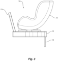
Figure 3 shows a side view of a child safety seat and base with the child seat in an in-use rear facing orientation, -
Figure 4A shows a part cross section view of the base, rotary element, latch and child seat in a latched position, -
Figure 4B shows a part cross section view of the base, rotary element, latch and child seat in an unlatched position, -
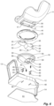
Figure 5 shows an exploded view from above (upper exploded view) of the components comprising the child safety seat and base, -
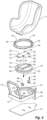
Figure 6 shows an exploded view from below (lower exploded view) of the components comprising the child safety seat and base, -
Figure 7 shows the child seat rotated 90 degrees from the rear facing in-use position, -
Figure 8 shows the base with the child seat removed with actuating pins in their upper position, -
Figures 9 and 10 show a cross section view ofFigure 8 , -
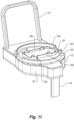
Figure 11 shows operation of the actuating pins in a downward direction, -
Figure 12 shows pins on the child seat pushing the actuating pins down as the seat is replaced on the base, -
Figures 13 to 17 show a sequence of replacing a child seat onto the base (seat not shown for clarity) and operation of the actuating pins and latch bars, -
Figure 18 shows an exploded view from above (upper exploded view) of an alternative child safety seat and base, -
Figure 19 shows an isometric view of the child safety seat and base ofFigure 18 with the seat detached from the base, -
Figures 20A and 20B show isometric views of a pull-release rotary element of the base ofFigures 18 and19 in a locked and released position respectively, -
Figures 21A and 21B show isometric views of an alternative rotary element of the base ofFigures 18 and19 in a locked and released position respectively, this alternative having a push-release instead of a pull-release, -
Figures 22 and23 show isometric views of the safety seat and base shown inFigures 18 and19 having the pull release ofFigures 21A and 21B in a loading and a locked position respectively, -
Figure 24 is a partial cutaway isometric view of a portion of the safety seat and base shown inFigures 18 and19 , -
Figures 25A and 25B are diagrammatic views of a pull-release mechanism within the rotary element ofFigures 20A and 20B , and -
Figures 26A and 26B are diagrammatic views of a push-release mechanism within the rotary element ofFigures 20A and 20B . - Referring to
Figures 1, 2 and3 , a child safety seat andbase 10 comprises achild seat 11 secured to thebase 12. Thebase 12 is designed to locate on and secure to the seat portion of a motor vehicle seat and optionally has arebound bar 13 that abuts against the backrest of the vehicle seat and, again optionally, a foot prop 14 (partially shown inFigures 1 and 2 ) to restrain rear and forward rotation respectively of thechild seat 11 andbase 12. Isofix connectors (not drawn) connect and secure the base 12 with respect to the vehicle seat. In other arrangements, not shown, the child safety seat andbase 10 may be arranged and constructed for belted installation using a motor vehicle's seat belts and a top tether or a foot prop for example. In further arrangements, not shown, the child safety seat andbase 10 may be arranged and constructed for installation by means of a latch system commonly used in the United States. - As seen in
Figures 1 to 3 , thechild seat 11 is in a rear facing in-use position. That is, the child will be facing the rear of the vehicle which is a position recommended for infants, babies and very young children. - With the
base 12 remaining in a fixed position with respect to a vehicle seat, thechild seat 11 is able to rotate through 360 degrees. As seen inFigure 4A , thechild seat 11 is secured to arotary element 18 and together, thechild seat 11 androtary element 18 are able to rotate about a substantially vertical axis on thebase 12. - A seat latch acts with the
rotary element 18 and the base 12 to hold thechild seat 11 in one of two in-use positions, either rear facing as shown inFigures 1 to 3 or forward facing. The seat latch may be manually operated, using ahandle 31, and once released, thechild seat 11 can be rotated to the opposite in-use position or to pre-determined intermediate positions. The intermediate positions are preferably 90 degrees from the in-use positions in either a clockwise or anticlockwise direction. This will have the advantage of positioning thechild seat 11 towards the open door of a motor vehicle. - The
rotary element 18 is provided with a seat latch which includes aseat latch body 20 as seen inFigures 4A and 4B . Theseat latch body 20 slides within therotary element 18 as will be described in detail below. Theseat latch body 20 is manually operated between a latched and unlatched position. - Referring to
Figures 5 and6 , therotary element 18 comprises a generally circular disc that locates into a complimentary shapedcavity 21 in thebase 12. Thecavity 21 has afloor 24. Therotary element 18 has aperipheral flange 22 that sits on a bearingsurface 23 on thebase 12, as is shown inFigure 5 , and therotary element 18 is held captive in thecavity 21 by aretainer 25 that has threadedfasteners 26 that secure it to thebase 12. - The
rotary element 18 has acavity 28 within which thelatch body 20 locates. Positioned around thecavity 28 is aU-shaped rim 29 located on theupper surface 19 of therotary element 18. Therim 29 has a number ofnotches 30 spaced around its periphery. - The
seat latch body 20 has an upturnedhandle 31 at the end of aplate 32 that extends from theseat latch body 20.Hooks 35 are located on the upper surface of both theplate 32 and thelatch body 20.Lugs 36 extend laterally from theseat latch body 20 at the lower edge of theseat latch body 20. A locking projection in the form of apin 37, shown inFigures 4 and6 , extends from an end of theseat latch body 20. - The
seat latch body 20 is located within thecavity 28 by inserting thehandle 31 through thecavity 28 from the underside of therotary element 18. Preferably, there is sufficient play within thecavity 28 or flexibility of some, or all, of the interlocking parts for theseat latch body 20 to be positioned to allow thepin 37 to locate into a locking recess in the form of anaperture 38. Alternatively, there may be provided a removable cover that allows thepin 37 to locate into theaperture 38. - The
lugs 36 locate incavities 39 on the underside surface of therotary element 18 as is shown inFigure 6 . Thecavities 39 allow back and forth movement of thelugs 36 as theseat latch body 20 is moved between its latched and unlatched positions ofFigures 4A and 4B respectively. The combination of thepin 37 and thelugs 36 slidably retain thelatch body 20 in thecavity 28 of therotary element 18. - Referring to
Figure 6 , the under surface of theseat 11 has abox 40 having a generally rectangular peripheral wall which is sized to locate over therim 29. Hook-engageable projections in the form ofpins 41 are located on the inner wall of thebox 40 and align with thenotches 30 of therim 29. As can be seen inFigure 4A , with thepins 41 located in thenotches 30 the seat is held to therotary element 18 with thehooks 35 positioned over thepins 41. -
Figure 7 shows thechild seat 11 rotated 90 degrees from the position shown inFigures 1 to 3 . A manual latch (not shown) is actuated to allow thechild seat 11 to move from its in-use position. Theretainer 25 has aflange 43 that extends around theretainer 25. Theflange 43 has twoopenings 44 positioned 90 degrees from the in-use positions. Theflange 43 prevents access to thehandle 31 in all but the 90 degree positions. However, theopenings 44 allow access to thehandle 31 when thechild seat 11 is rotated to this pre-determined position. - As seen in
Figure 4A , the end of thepin 37 abuts against the wall of thecavity 21 below the bearingsurface 23, aside from when it aligns with anaperture 38 that is provided at two diametrically opposite loading positions. This prevents unlatching movement of the latchingbody 20. As theseat 11 and rotary element are rotated, the latch body moves with them both. When they are rotated 90 degrees to the pre-determined position, thepin 37 aligns with anaperture 38 in the wall of thecavity 21 as is shown inFigure 4B . In this position, thehandle 31 is accessible and can now be pushed inwardly. Thepin 37, sliding within through-hole 38', can enter theaperture 38 and the latch body is moved so that thehooks 35 are clear of thepins 41. In this position, theseat 11 is unlatched and can be removed from thebase 12. - Engagement of the
pin 37 in theaperture 38 will allow thelatch body 20 to move into a position that is open and theseat 11 can be removed. However,base 12 can be arranged to prevent thelatch body 20 moving back to a closed position and to prevent the rotary element rotating while theseat 11 is removed. - An interlock is provided which comprises spring loaded actuating pins 45 and spring loaded interlock latches in the form of latch bars 46. As seen in
Figures 9 and 10 , the latch bars 46 are mounted inslots 48 in thefloor 24 of thecavity 21. The latch bars 46 have pivot pins 49 that engage apertures in theslots 48. This allows upward pivoting movement of the latch bars 46 within theslots 48. The latch bars 46 are biased upwardly bysprings 50 that are held in place below the latch bars 46 by abase plate 51. Thesprings 50 may have pivot pins that also engage pivot holes in theslots 48 and have hooks at their ends that engage retaining holes in both thelatch bar 46 and thebase 51. - In this manner, the latch bars 46 are held in the
floor 24 of thecavity 21 with the base of therotary element 18 moving over them as it rotates. - The actuating pins 45 are mounted in the rotary element and move with it as it is rotated. As seen in
Figure 8 , with theseat 11 removed the actuating pins 45 are urged upwardly by springs 52. As seen inFigures 9 and 10 , the actuating pins 45 with springs 52 are mounted in abore 53. The actuating pins havecollars 54 against which the springs 52 act to push theactuating pin 45 upwardly into the position shown inFigures 8 to 10 . - When the
rotary element 18 is aligned in its 90 degree position, thelatch body 20 can be moved to the unlatch position where theseat 11 can be removed. This is the position shown inFigures 9 and 10 . In this position,slots 56 in the base of the rotary element 18 (seeFigure 6 ) align with the latch bars 46. The upward biasing of thesprings 50 results in the latch bars 46 pivoting upwardly so that their ends locate into theslots 56 shown onFigure 6 . - With the latch bars 46 in the
slots 56, therotary element 18 is fixed in position and cannot rotate away from the position from where theseat 11 was removed. Also, the ends 46' oflatch bar 46 block movement of thelugs 36 and so in this position, thelatch body 20 cannot be moved away from the unlatched position as is illustrated inFigures 9 and 10 . - This prevents the
rotary element 18 from moving out of position once the seat is removed. - Upon replacing the
seat 11 onto the base, thebox 40 has interlock pins 58, visible inFigure 12 , that, as thepins 41 locate into thenotches 30, press against the top of the actuating pins 45 and press them downwardly. This is against the biasing of springs 52. The lower ends of the actuating pins 45 press the respective latch bars 46 down so that, as seen inFigure 12 , the top surface of the latch bars 46 are level with the base of therotary element 18. This also results in the end of thelatch bar 46 being clear of theslots 56. - In this position, the
latch body 20 can be moved to the latched position with thehooks 35 again locating over thepins 41. With the latch bars 46 in their lower position, thelugs 36 are now able to move over the latch bars 46 as seen inFigure 12 . - With the latch bars 46 below the base of the
rotary element 18 and theseat 11 again latched to thebase 12, therotary element 18 andseat 11 are free to rotate away from a 90 degree position into an in-use position where it is latched in place. - While in the example illustrated in
Figures 1 to 17 interlock pins 58 are described separately from hook-engageable pins 41, in some example the same extended pin will serve the function of both interlock pins 58 and hook-engageable pins 41. - Turning now to
Figures 18 to 24 , an alternative child safety seat and base combination is shown. In the exploded view ofFigure 18 , theseat 11 and itsbox 40 are the same, or largely the same as those shown inFigure 6 . However therotary element 18 and the seat latch are different. With this example, two pairs ofhooks 35 face each other as is shown more clearly inFigures 20A and 20B . This provides a reduced vulnerability against acceleration or deceleration as compared to an arrangement ofhooks 35 that all face in the same direction as shown inFigures 1 to 17 . The arrangement shown inFigures 20A and 20B therefore may provide better resistance to unwanted release in the event of a frontal or rearward impact in a motor vehicle accident. -
Figures 18 and19 show achild safety seat 11 andbase 12 assembly wherein abase 11 is arranged to be secured with respect to a motor vehicle and a seat is arranged to be removably secured with respect to the base. The assembly includes arotary element 18, rotatably mounted to the base (most clearly shown inFigure 19 ). Thechild seat 11 is securable to therotary element 18 and together, thechild seat 11 androtary element 18 are able to rotate about a substantially vertical axis on thebase 12. Apivot bearing support 70 on thebase 12 is shown inFigure 18 . A corresponding attachment feature (not shown) is provided on the underside of therotary element 18 thereby providing the substantially vertical axis. - A seat latch is provided on the rotary element that engages the child safety seat to releasably hold the child safety seat with respect to the base and rotary element. The seat latch includes a plurality of
hooks 35 and hook-engageable projections 41 as shown inFigure 24 . In the example illustrated inFigure 24 , it can be seen that the hook-engageable projections are in the form of hook engageable pins 41. - The
hooks 35 are movable from a latching position in which they hold the hook-engageable projections, as shown inFigures 20A and21A , to a released position in which they do not hold the projections, as shown inFigures 20B and21B . -
Figures 20A and 20B on the one hand, andFigures 21A and 21B on the other hand, show alternative arrangements. With the arrangement ofFigures 20A and 20B , a pull-release mechanism within the rotary element is provided. In contrast, with the arrangement ofFigures 21A and 21B , a push-release mechanism within the rotary element is provided. - Referring to
Figures 18 ,19 ,22 and23 , it can be seen that the base 12 blocks access to thehandle 31 when theseat 11 is in any position other than one or two side-loading position, thereby preventing opening or closing the seat latch when the seat is in any position other than side-loading position(s). For example, when in the driving position illustrated inFigure 23 , it is impossible for a user to access and actuate thehandle 31. This prevents inadvertent or unsafe release of thehooks 35 from their securing positions shown inFigure 24 for instance. - The assembly further includes a seat latch actuation assembly for opening or closing the seat latch wherein opening the seat latch releases the child safety seat. The seat latch actuation assembly includes a
handle 31 slidably mounted with respect to the rotary element. - Referring now to
Figures 18 ,20B and21B , an interlock mechanism, actuated upon opening the seat latch, is shown. The interlock mechanism prevents rotation of therotary element 18 with respect to thebase 12. The interlock mechanism includes a locking projection, in the form of apin 37 and a locking recess, in the form of anaperture 38. Thepin 37 is engageable with theaperture 38 to prevent rotation of therotary element 18 with respect to the base 12 when the seat latch is opened. - The
pin 37 extends from therotary element 18 when thehooks 35 are open as can be seen inFigures 20B ,25B ,21B and26B . - The
aperture 38 is formed in the base 12 as is shown inFigure 18 . - The
rotary element 18 includes a depressable element in the form of anactuating pin 45 as shown inFigures 18 and19 . Multiple actuating pins 45 may be provided as is more clearly shown in the first example as is illustrated inFigure 8 for instance. Thepins 45 are engageable by a seat-depending surface in the form of aninterlock pin 58, or pins 58, as are shown inFigure 22 . In the example illustrated, the depressible pins 45 are depressible by thepins 58 on the seat to release the interlock mechanism. - As with the first example described above, the depressible interlock pin or pins 45 are biased toward an upper position in which the interlock mechanism locks, thereby preventing rotation of the
rotary element 18 with respect to thebase 12. Furthermore the interlock mechanism includes aninterlock latch 46, the interlock latch is actuated by theinterlock pin 45 as is illustrated inFigures 9 and 10 . Theinterlock latch 46 is biased towards an upper position in which an end face 46' of theinterlock latch 46 blocks movement of thehandle 31, thereby preventing deactivation of the interlock mechanism until theinterlock pin 45 is depressed. As can be seen inFigures 8 and9 , the interlock latch is pivotally mounted to therotary element 18. - Various internal mechanisms can be provided within or on the
rotary element 18 to provide the functionality of the seat latch actuation and interlock mechanisms. These mechanisms may be separate or integrated as is shown by the non-limiting examples ofFigures 25A and 25B and in the alternatives ofFigures 26A and 26B . - Referring to
Figures 25A and 25B , it can be seen that ahandle linkage 80, that is either operatively connected to thehandle 31 or forms part of thehandle 31, is pivotally connected to apair hook linkages 90 at pivot points 95 and 96. This arrangement is the pull-release mechanism within therotary element 18 shown inFigures 20A and 20B respectively. - Referring to
Figures 26A and 26B , a similar arrangement to that ofFigures 25A and 25B is shown. However the arrangement is the push-release mechanism within therotary element 18 shown inFigures 21A and 21B respectively. - The operating of the actuating pins 45 and the latch bars 46 are shown sequentially in
Figures 13 to 17 . Starting atFigure 13 , placement of theseat 11 onto the base 12 (seat 11 not shown for clarity), results in thepins 58 depressing the actuating pins 45 which in turn push the latch bars 46 into their lower position (Figures 13 and 14 ) from their upper position shown inFigures 9 and 10 . With thelugs 36 now no longer blocked by faces 46' on the ends of the latch bars 46, thelatch body 20 moves to its latched position seen inFigures 15 to 17 . Theseat 11 is latched and therotary element 18 is free to rotate. -
Figures 11 to 17 show theseat 11 being removed from the right hand side of thebase 12. The latch bars 46 are on the left side of the base 12 to allow theapertures 56 to align in this position. A further set of latch bars 46 would need to be provided on the right side of the base 12 in order to allow removal of theseat 11 from the left side of thebase 12. These have not been drawn, but it will be apparent to a skilled addressee as to the required location of these additional latch bars 46. - As can be seen from the above description, the described example provides a means of rotating a
seat 11 to a 90 degree position and for it to be removed from a base 12 only when in that position. Further, interlocks are provided that prevent therotary element 18 moving while theseat 11 is removed. This prevents theseat 11 being removed when in a position other than the pre-determined position and ensures theseat 11 is repositioned in the correct orientation on the base. It also prevents therotary element 18 moving out of position while the seat is removed.
Claims (12)
- A child safety seat and base assembly (10) wherein a base (12) is arranged to be secured with respect to a motor vehicle and a seat (11) is arranged to be removably secured with respect to the base (12), the assembly (10) including:a rotary element (18) rotatably mounted to the base (12);a seat latch (20) on the rotary element (18) that engages the child safety seat (11) to releasably hold the child safety seat (11) with respect to the base (12) and rotary element (18);a seat latch actuation assembly for opening or closing the seat latch (20) wherein opening the seat latch (20) releases the child safety seat (11); andan interlock mechanism actuated upon opening the seat latch (20) that prevents rotation of the rotary element (18) with respect to the base (12).
- The child safety seat and base assembly (10) as claimed in claim 1, wherein the seat latch actuation assembly includes a handle (31) slidably mounted with respect to the rotary element (18).
- The child safety seat and base assembly (10) as claimed in claim 1, wherein, in use, the base (12) blocks access to the handle (31) when the seat (11) is in any position other than one or two side-loading position(s), thereby preventing opening or closing the seat latch (20) when the seat (11) is in any position other than the one or two side-loading position(s).
- The child safety seat and base assembly (10) as claimed in claim 1 including a plurality of hooks (35) and hook-engageable projections (41), the hooks (35) movable from a latching position in which they hold the hook-engageable projections (41), to a released position in which they do not hold the projections (41).
- The child safety seat and base assembly (10) as claimed in claim 3, wherein the hooks (35) are located on the rotary element (18) and form part of the seat latch (20) and the hook-engageable projections (41) are located on the seat (11).
- The child safety seat and base assembly (10) as claimed in claim 1, wherein the interlock mechanism includes a locking projection (37) and a locking recess (38), the locking projection (37) engageable with the locking recess (38) to prevent rotation of the rotary element (18) with respect to the base (12) when the seat latch (20) is opened.
- The child safety seat and base assembly (10) as claimed in claim 6, wherein the locking projection (37) extends from the rotary element (18) and the locking recess (38) is formed in the base (12).
- The child safety seat and base assembly (10) as claimed in claim 7, wherein the rotary element (18) includes a depressible element engageable by a seat-depending surface,
whereby the depressible element is depressible by the seat-depending surface to release the interlock mechanism. - The child safety seat and base assembly (10) as claimed in claim 8, wherein the depressible element includes an interlock pin (45), the interlock pin (45) biased toward an upper position in which the interlock mechanism locks, thereby preventing rotation of the rotary element (18) with respect to the base (12).
- The child safety seat and base assembly (10) as claimed in claim 9, wherein the interlock mechanism includes an interlock latch (46), the interlock latch (46) actuated by the interlock pin (45).
- The child safety seat and base assembly (10) as claimed in claim 10, wherein the interlock latch (46) is biased towards an upper position in which an end face (46') of the interlock latch (46) blocks movement of the handle (31), thereby preventing deactivation of the interlock mechanism until the interlock pin (45) is depressed.
- The child safety seat and base assembly (10) as claimed in claim 11, wherein the interlock latch (46) is pivotally mounted to the rotary element (18).
Applications Claiming Priority (1)
| Application Number | Priority Date | Filing Date | Title |
|---|---|---|---|
| AU2022200286A AU2022200286C1 (en) | 2022-01-17 | 2022-01-17 | A child safety seat rotatably mounted on a base |
Publications (2)
| Publication Number | Publication Date |
|---|---|
| EP4212388A1 true EP4212388A1 (en) | 2023-07-19 |
| EP4212388B1 EP4212388B1 (en) | 2024-11-06 |
Family
ID=84786734
Family Applications (1)
| Application Number | Title | Priority Date | Filing Date |
|---|---|---|---|
| EP23150380.6A Active EP4212388B1 (en) | 2022-01-17 | 2023-01-05 | A child safety seat rotatably mounted on a base |
Country Status (4)
| Country | Link |
|---|---|
| US (2) | US12246629B2 (en) |
| EP (1) | EP4212388B1 (en) |
| CN (2) | CN116442868A (en) |
| AU (1) | AU2022200286C1 (en) |
Families Citing this family (8)
| Publication number | Priority date | Publication date | Assignee | Title |
|---|---|---|---|---|
| AU2022200286C1 (en) * | 2022-01-17 | 2024-05-02 | BRITAX RÖMER Kindersicherheit GmbH | A child safety seat rotatably mounted on a base |
| US12344130B2 (en) * | 2022-04-27 | 2025-07-01 | Toyota Motor Engineering & Manufacturing North America, Inc. | Adjustable vehicle seat attachment system |
| US12017565B2 (en) * | 2022-08-25 | 2024-06-25 | Brooky Grubbs | Rotatable vehicle seat assembly |
| US12496941B1 (en) * | 2022-11-15 | 2025-12-16 | Artsana Usa, Inc. | Keyed release of secondary locking mechanism |
| US12472852B2 (en) * | 2022-11-17 | 2025-11-18 | Dorel Juvenile Group, Inc. | Child restraint |
| US20250135966A1 (en) * | 2023-10-25 | 2025-05-01 | Dorel Juvenile Group, Inc. | Child restraint |
| TW202532267A (en) * | 2024-01-18 | 2025-08-16 | 瑞士商明門瑞士股份有限公司 | Child vehicle seat system |
| US20250326338A1 (en) * | 2024-04-23 | 2025-10-23 | Evenflo Company, Inc. | Rotatable car seat with locking feature |
Citations (5)
| Publication number | Priority date | Publication date | Assignee | Title |
|---|---|---|---|---|
| EP2308716A1 (en) * | 2008-07-02 | 2011-04-13 | Combi Corporation | Child seat |
| EP2308715A1 (en) * | 2008-07-02 | 2011-04-13 | Combi Corporation | Child seat |
| DE202017105584U1 (en) * | 2017-09-14 | 2018-12-17 | Cybex Gmbh | Child seat system, comprising a seat member and a mountable on a motor vehicle seat base |
| US20200391627A1 (en) * | 2019-06-12 | 2020-12-17 | Wonderland Switzerland Ag | Child safety seat and related spin lock mechanism |
| CN213920753U (en) * | 2020-08-04 | 2021-08-10 | 广东乐美达集团有限公司 | Rotation type car children safety seat base and car children safety seat |
Family Cites Families (19)
| Publication number | Priority date | Publication date | Assignee | Title |
|---|---|---|---|---|
| JP4434394B2 (en) | 1999-12-21 | 2010-03-17 | コンビ株式会社 | Swivel child seat |
| FR2812253B1 (en) * | 2000-07-26 | 2004-03-05 | Renolux France Ind | AUTOMOTIVE SAFETY DEVICE FOR A CHILD WITH AN INDEPENDENT BASE |
| US7338122B2 (en) | 2004-05-17 | 2008-03-04 | Orbit Baby, Inc. | Modular child restraint system |
| FR2905315B1 (en) | 2006-09-01 | 2008-12-05 | Dorel France Sa Sa | CHILD CAR SEAT BETWEEN AN OPERATING POSITION AND AT LEAST ONE INSTALLATION POSITION |
| EP1970247A1 (en) | 2007-03-15 | 2008-09-17 | Team-Tex | Device for mounting a child seat in a car and a child seat |
| NL1036453C2 (en) | 2009-01-23 | 2010-07-26 | Maxi Miliaan Bv | Child vehicle seat. |
| EP2295287B1 (en) * | 2009-09-14 | 2012-08-01 | BÉBÉCAR - Utilidades para Criança, S.A. | Fixing base for a child car seat |
| CN104290619B (en) * | 2013-07-18 | 2016-09-14 | 明门香港股份有限公司 | Rotatable automobile safety seat |
| US9572435B2 (en) | 2014-03-10 | 2017-02-21 | Graco Children's Products Inc. | Child booster seat with swivel capability |
| EP3294590A4 (en) | 2015-05-12 | 2019-01-23 | Pidyon Controls Inc. | CAR SEAT AND CONNECTION SYSTEM |
| US10829012B1 (en) | 2017-01-23 | 2020-11-10 | Graco Children's Products, Inc. | Method and apparatus for a rotatable child safety seat |
| DE102018010420B3 (en) * | 2017-03-17 | 2022-11-03 | Wonderland Switzerland Ag | child safety seat |
| DE102020115498B4 (en) | 2019-06-12 | 2022-09-29 | Wonderland Switzerland Ag | Twist lock mechanism and relative child seat |
| CN110497826B (en) * | 2019-09-27 | 2022-05-24 | 创是实业(香港)有限公司 | Safety seat base control assembly, safety seat base, kit and control method |
| US11584267B2 (en) * | 2020-02-05 | 2023-02-21 | Artsana Usa, Inc. | Rotatable car seat with detachable seat and top anchor |
| US11427114B2 (en) | 2020-08-14 | 2022-08-30 | Evenflo Company, Inc. | Booster seat to base attachment mechanism |
| CN114801914A (en) | 2021-01-28 | 2022-07-29 | 宝钜瑞士股份有限公司 | Anti-rotation misuse device and seat |
| AU2022200286C1 (en) * | 2022-01-17 | 2024-05-02 | BRITAX RÖMER Kindersicherheit GmbH | A child safety seat rotatably mounted on a base |
| CN221023362U (en) | 2022-05-20 | 2024-05-28 | 明门(中国)幼童用品有限公司 | Child safety seat and safety belt installation prompting system |
-
2022
- 2022-01-17 AU AU2022200286A patent/AU2022200286C1/en active Active
-
2023
- 2023-01-04 US US18/093,036 patent/US12246629B2/en active Active
- 2023-01-05 EP EP23150380.6A patent/EP4212388B1/en active Active
- 2023-01-13 CN CN202310071462.1A patent/CN116442868A/en active Pending
- 2023-01-13 CN CN202320137408.8U patent/CN223266662U/en active Active
-
2025
- 2025-02-13 US US19/053,163 patent/US20250178493A1/en active Pending
Patent Citations (5)
| Publication number | Priority date | Publication date | Assignee | Title |
|---|---|---|---|---|
| EP2308716A1 (en) * | 2008-07-02 | 2011-04-13 | Combi Corporation | Child seat |
| EP2308715A1 (en) * | 2008-07-02 | 2011-04-13 | Combi Corporation | Child seat |
| DE202017105584U1 (en) * | 2017-09-14 | 2018-12-17 | Cybex Gmbh | Child seat system, comprising a seat member and a mountable on a motor vehicle seat base |
| US20200391627A1 (en) * | 2019-06-12 | 2020-12-17 | Wonderland Switzerland Ag | Child safety seat and related spin lock mechanism |
| CN213920753U (en) * | 2020-08-04 | 2021-08-10 | 广东乐美达集团有限公司 | Rotation type car children safety seat base and car children safety seat |
Also Published As
| Publication number | Publication date |
|---|---|
| EP4212388B1 (en) | 2024-11-06 |
| US12246629B2 (en) | 2025-03-11 |
| AU2022200286C1 (en) | 2024-05-02 |
| CN116442868A (en) | 2023-07-18 |
| US20250178493A1 (en) | 2025-06-05 |
| US20230226957A1 (en) | 2023-07-20 |
| CN223266662U (en) | 2025-08-26 |
| AU2022200286B1 (en) | 2023-01-12 |
Similar Documents
| Publication | Publication Date | Title |
|---|---|---|
| EP4212388B1 (en) | A child safety seat rotatably mounted on a base | |
| US9415707B2 (en) | Child safety seat | |
| CA2940813C (en) | Infant carrier | |
| US4382622A (en) | Door lock for vehicle | |
| US10023079B2 (en) | Child safety seat | |
| US7246855B2 (en) | Recline mechanism for a child seat | |
| EP0602696A1 (en) | Vehicle seat | |
| US6626472B1 (en) | Load floor latch | |
| US4667492A (en) | Locking device for a seat back of a trunk through-seat(sic) | |
| AU2024200902A1 (en) | A child vehicle seat as well as a base suitable for such a child vehicle seat | |
| JP3694728B2 (en) | Vehicle seat lock device | |
| EP0123251B1 (en) | Door lock device | |
| US20050184567A1 (en) | Lock-off mechanism for a child seat | |
| EP4232664B1 (en) | Double-pull vehicle lock with safety catch | |
| JP4439647B2 (en) | Child seat fixing device | |
| JP2024504311A (en) | Rotation misuse prevention device and seat | |
| US5205023A (en) | Child-resistant buckle and buckle guard combination | |
| KR101361742B1 (en) | Detent fitting for locking two vehicle parts | |
| JPH07304359A (en) | Vehicle seat | |
| US3287049A (en) | Vehicle latch | |
| JPH11113669A (en) | Car seat | |
| US20260061900A1 (en) | Rotating car seat | |
| JPH0629409Y2 (en) | Sliding door opening prevention device | |
| JPH067970Y2 (en) | Seat back lock mechanism | |
| KR20070031493A (en) | Folding position limiter for double folding seats |
Legal Events
| Date | Code | Title | Description |
|---|---|---|---|
| PUAI | Public reference made under article 153(3) epc to a published international application that has entered the european phase |
Free format text: ORIGINAL CODE: 0009012 |
|
| STAA | Information on the status of an ep patent application or granted ep patent |
Free format text: STATUS: THE APPLICATION HAS BEEN PUBLISHED |
|
| AK | Designated contracting states |
Kind code of ref document: A1 Designated state(s): AL AT BE BG CH CY CZ DE DK EE ES FI FR GB GR HR HU IE IS IT LI LT LU LV MC ME MK MT NL NO PL PT RO RS SE SI SK SM TR |
|
| STAA | Information on the status of an ep patent application or granted ep patent |
Free format text: STATUS: REQUEST FOR EXAMINATION WAS MADE |
|
| 17P | Request for examination filed |
Effective date: 20240119 |
|
| RBV | Designated contracting states (corrected) |
Designated state(s): AL AT BE BG CH CY CZ DE DK EE ES FI FR GB GR HR HU IE IS IT LI LT LU LV MC ME MK MT NL NO PL PT RO RS SE SI SK SM TR |
|
| GRAP | Despatch of communication of intention to grant a patent |
Free format text: ORIGINAL CODE: EPIDOSNIGR1 |
|
| STAA | Information on the status of an ep patent application or granted ep patent |
Free format text: STATUS: GRANT OF PATENT IS INTENDED |
|
| INTG | Intention to grant announced |
Effective date: 20240726 |
|
| GRAS | Grant fee paid |
Free format text: ORIGINAL CODE: EPIDOSNIGR3 |
|
| GRAA | (expected) grant |
Free format text: ORIGINAL CODE: 0009210 |
|
| STAA | Information on the status of an ep patent application or granted ep patent |
Free format text: STATUS: THE PATENT HAS BEEN GRANTED |
|
| AK | Designated contracting states |
Kind code of ref document: B1 Designated state(s): AL AT BE BG CH CY CZ DE DK EE ES FI FR GB GR HR HU IE IS IT LI LT LU LV MC ME MK MT NL NO PL PT RO RS SE SI SK SM TR |
|
| REG | Reference to a national code |
Ref country code: GB Ref legal event code: FG4D |
|
| REG | Reference to a national code |
Ref country code: CH Ref legal event code: EP |
|
| REG | Reference to a national code |
Ref country code: DE Ref legal event code: R096 Ref document number: 602023000888 Country of ref document: DE |
|
| REG | Reference to a national code |
Ref country code: IE Ref legal event code: FG4D |
|
| REG | Reference to a national code |
Ref country code: LT Ref legal event code: MG9D |
|
| REG | Reference to a national code |
Ref country code: NL Ref legal event code: MP Effective date: 20241106 |
|
| PG25 | Lapsed in a contracting state [announced via postgrant information from national office to epo] |
Ref country code: HR Free format text: LAPSE BECAUSE OF FAILURE TO SUBMIT A TRANSLATION OF THE DESCRIPTION OR TO PAY THE FEE WITHIN THE PRESCRIBED TIME-LIMIT Effective date: 20241106 Ref country code: PT Free format text: LAPSE BECAUSE OF FAILURE TO SUBMIT A TRANSLATION OF THE DESCRIPTION OR TO PAY THE FEE WITHIN THE PRESCRIBED TIME-LIMIT Effective date: 20250306 Ref country code: IS Free format text: LAPSE BECAUSE OF FAILURE TO SUBMIT A TRANSLATION OF THE DESCRIPTION OR TO PAY THE FEE WITHIN THE PRESCRIBED TIME-LIMIT Effective date: 20250306 |
|
| PG25 | Lapsed in a contracting state [announced via postgrant information from national office to epo] |
Ref country code: NL Free format text: LAPSE BECAUSE OF FAILURE TO SUBMIT A TRANSLATION OF THE DESCRIPTION OR TO PAY THE FEE WITHIN THE PRESCRIBED TIME-LIMIT Effective date: 20241106 Ref country code: FI Free format text: LAPSE BECAUSE OF FAILURE TO SUBMIT A TRANSLATION OF THE DESCRIPTION OR TO PAY THE FEE WITHIN THE PRESCRIBED TIME-LIMIT Effective date: 20241106 |
|
| REG | Reference to a national code |
Ref country code: AT Ref legal event code: MK05 Ref document number: 1739037 Country of ref document: AT Kind code of ref document: T Effective date: 20241106 |
|
| PG25 | Lapsed in a contracting state [announced via postgrant information from national office to epo] |
Ref country code: BG Free format text: LAPSE BECAUSE OF FAILURE TO SUBMIT A TRANSLATION OF THE DESCRIPTION OR TO PAY THE FEE WITHIN THE PRESCRIBED TIME-LIMIT Effective date: 20241106 |
|
| PG25 | Lapsed in a contracting state [announced via postgrant information from national office to epo] |
Ref country code: ES Free format text: LAPSE BECAUSE OF FAILURE TO SUBMIT A TRANSLATION OF THE DESCRIPTION OR TO PAY THE FEE WITHIN THE PRESCRIBED TIME-LIMIT Effective date: 20241106 |
|
| PG25 | Lapsed in a contracting state [announced via postgrant information from national office to epo] |
Ref country code: NO Free format text: LAPSE BECAUSE OF FAILURE TO SUBMIT A TRANSLATION OF THE DESCRIPTION OR TO PAY THE FEE WITHIN THE PRESCRIBED TIME-LIMIT Effective date: 20250206 |
|
| PG25 | Lapsed in a contracting state [announced via postgrant information from national office to epo] |
Ref country code: LV Free format text: LAPSE BECAUSE OF FAILURE TO SUBMIT A TRANSLATION OF THE DESCRIPTION OR TO PAY THE FEE WITHIN THE PRESCRIBED TIME-LIMIT Effective date: 20241106 Ref country code: GR Free format text: LAPSE BECAUSE OF FAILURE TO SUBMIT A TRANSLATION OF THE DESCRIPTION OR TO PAY THE FEE WITHIN THE PRESCRIBED TIME-LIMIT Effective date: 20250207 Ref country code: AT Free format text: LAPSE BECAUSE OF FAILURE TO SUBMIT A TRANSLATION OF THE DESCRIPTION OR TO PAY THE FEE WITHIN THE PRESCRIBED TIME-LIMIT Effective date: 20241106 |
|
| PG25 | Lapsed in a contracting state [announced via postgrant information from national office to epo] |
Ref country code: PL Free format text: LAPSE BECAUSE OF FAILURE TO SUBMIT A TRANSLATION OF THE DESCRIPTION OR TO PAY THE FEE WITHIN THE PRESCRIBED TIME-LIMIT Effective date: 20241106 |
|
| PG25 | Lapsed in a contracting state [announced via postgrant information from national office to epo] |
Ref country code: RS Free format text: LAPSE BECAUSE OF FAILURE TO SUBMIT A TRANSLATION OF THE DESCRIPTION OR TO PAY THE FEE WITHIN THE PRESCRIBED TIME-LIMIT Effective date: 20250206 |
|
| PG25 | Lapsed in a contracting state [announced via postgrant information from national office to epo] |
Ref country code: SM Free format text: LAPSE BECAUSE OF FAILURE TO SUBMIT A TRANSLATION OF THE DESCRIPTION OR TO PAY THE FEE WITHIN THE PRESCRIBED TIME-LIMIT Effective date: 20241106 |
|
| PG25 | Lapsed in a contracting state [announced via postgrant information from national office to epo] |
Ref country code: DK Free format text: LAPSE BECAUSE OF FAILURE TO SUBMIT A TRANSLATION OF THE DESCRIPTION OR TO PAY THE FEE WITHIN THE PRESCRIBED TIME-LIMIT Effective date: 20241106 |
|
| PG25 | Lapsed in a contracting state [announced via postgrant information from national office to epo] |
Ref country code: EE Free format text: LAPSE BECAUSE OF FAILURE TO SUBMIT A TRANSLATION OF THE DESCRIPTION OR TO PAY THE FEE WITHIN THE PRESCRIBED TIME-LIMIT Effective date: 20241106 |
|
| PG25 | Lapsed in a contracting state [announced via postgrant information from national office to epo] |
Ref country code: RO Free format text: LAPSE BECAUSE OF FAILURE TO SUBMIT A TRANSLATION OF THE DESCRIPTION OR TO PAY THE FEE WITHIN THE PRESCRIBED TIME-LIMIT Effective date: 20241106 |
|
| PG25 | Lapsed in a contracting state [announced via postgrant information from national office to epo] |
Ref country code: SK Free format text: LAPSE BECAUSE OF FAILURE TO SUBMIT A TRANSLATION OF THE DESCRIPTION OR TO PAY THE FEE WITHIN THE PRESCRIBED TIME-LIMIT Effective date: 20241106 |
|
| PG25 | Lapsed in a contracting state [announced via postgrant information from national office to epo] |
Ref country code: CZ Free format text: LAPSE BECAUSE OF FAILURE TO SUBMIT A TRANSLATION OF THE DESCRIPTION OR TO PAY THE FEE WITHIN THE PRESCRIBED TIME-LIMIT Effective date: 20241106 |
|
| PG25 | Lapsed in a contracting state [announced via postgrant information from national office to epo] |
Ref country code: IT Free format text: LAPSE BECAUSE OF FAILURE TO SUBMIT A TRANSLATION OF THE DESCRIPTION OR TO PAY THE FEE WITHIN THE PRESCRIBED TIME-LIMIT Effective date: 20241106 |
|
| REG | Reference to a national code |
Ref country code: DE Ref legal event code: R097 Ref document number: 602023000888 Country of ref document: DE |
|
| PG25 | Lapsed in a contracting state [announced via postgrant information from national office to epo] |
Ref country code: SE Free format text: LAPSE BECAUSE OF FAILURE TO SUBMIT A TRANSLATION OF THE DESCRIPTION OR TO PAY THE FEE WITHIN THE PRESCRIBED TIME-LIMIT Effective date: 20241106 |
|
| PLBE | No opposition filed within time limit |
Free format text: ORIGINAL CODE: 0009261 |
|
| STAA | Information on the status of an ep patent application or granted ep patent |
Free format text: STATUS: NO OPPOSITION FILED WITHIN TIME LIMIT |
|
| PG25 | Lapsed in a contracting state [announced via postgrant information from national office to epo] |
Ref country code: LU Free format text: LAPSE BECAUSE OF NON-PAYMENT OF DUE FEES Effective date: 20250105 Ref country code: MC Free format text: LAPSE BECAUSE OF FAILURE TO SUBMIT A TRANSLATION OF THE DESCRIPTION OR TO PAY THE FEE WITHIN THE PRESCRIBED TIME-LIMIT Effective date: 20241106 |
|
| 26N | No opposition filed |
Effective date: 20250807 |
|
| PG25 | Lapsed in a contracting state [announced via postgrant information from national office to epo] |
Ref country code: BE Free format text: LAPSE BECAUSE OF NON-PAYMENT OF DUE FEES Effective date: 20250131 |
|
| REG | Reference to a national code |
Ref country code: BE Ref legal event code: MM Effective date: 20250131 |
|
| PG25 | Lapsed in a contracting state [announced via postgrant information from national office to epo] |
Ref country code: IE Free format text: LAPSE BECAUSE OF NON-PAYMENT OF DUE FEES Effective date: 20250105 |
|
| PGFP | Annual fee paid to national office [announced via postgrant information from national office to epo] |
Ref country code: DE Payment date: 20260120 Year of fee payment: 4 |
|
| PGFP | Annual fee paid to national office [announced via postgrant information from national office to epo] |
Ref country code: FR Payment date: 20260123 Year of fee payment: 4 |